JP5277721B2 - Game machine - Google Patents
Game machine Download PDFInfo
- Publication number
- JP5277721B2 JP5277721B2 JP2008131093A JP2008131093A JP5277721B2 JP 5277721 B2 JP5277721 B2 JP 5277721B2 JP 2008131093 A JP2008131093 A JP 2008131093A JP 2008131093 A JP2008131093 A JP 2008131093A JP 5277721 B2 JP5277721 B2 JP 5277721B2
- Authority
- JP
- Japan
- Prior art keywords
- light emitting
- side terminal
- command
- symbol
- main body
- Prior art date
- Legal status (The legal status is an assumption and is not a legal conclusion. Google has not performed a legal analysis and makes no representation as to the accuracy of the status listed.)
- Expired - Fee Related
Links
Images


Abstract
Description
本発明は、パチンコ機等の遊技機に関するものである。 The present invention relates to a gaming machine such as a pachinko machine.
遊技機の一種としてパチンコ機がある。パチンコ機では、例えば、発射装置にて打ち出された遊技球が案内される遊技領域に設けられた始動入球手段に遊技球が入球すると当たり状態を発生させるか否かの当否抽選が行われる。前記当否抽選にて当選した場合には、遊技者に有利な当たり状態が発生し、遊技者は遊技価値(賞球)を獲得することが可能となる。 One type of gaming machine is a pachinko machine. The pachinko machines, for example, whether the spruce lottery game ball that is struck by the firing device generates an equivalent or state when the gaming ball is ball entrance to the starting ball entrance means provided in the game area to be guided Done. The spruce in the case of winning in the lottery is advantageous tow or condition occurs to the player, the player it is possible to win the Yu skill value (winning balls).
このような遊技機においては、装飾効果や演出効果を高めるべく、液晶表示装置や電飾手段等が設けられている(例えば、特許文献1参照)。
しかしながら、単に電飾手段の数を増やしたり、液晶画面を大きくしたりするだけでは目新しさがなく、遊技者の興趣を向上させるといった効果がそれ程見込めないおそれがある。 Nevertheless, simply or increase the number of illuminations means alone is no novelty or larger LCD screen, there is a possibility that the effect is not expected so much like to improve the player's interest.
なお、上述した課題は、パチンコ機に限られるものではなく、スロットマシン等の他の遊技機にも該当する問題である。 Note that the above-described problem is not limited to pachinko machines, but also applies to other gaming machines such as slot machines.
本発明は、上記例示した問題点等を解決するためになされたものであり、その目的は、斬新な光の態様を導出することのできる電飾手段を備えた遊技機を提供することにある。 The present invention has been made to solve the above-described problems and the like, and an object of the present invention is to provide a gaming machine provided with an electric decoration means capable of deriving a novel light mode. .
本発明の遊技機は、
遊技機の前面に設けられた被取付部に固定される本体部と、
発光色の異なる複数の発光部を具備する複数の発光手段と、
前記発光手段が搭載され、前記本体部に対して相対変位可能な発光体ブロックと、
前記発光体ブロックを変位させることのできる駆動手段と、
前記発光体ブロックを上方から覆うようにして設けられ、少なくとも一部において透光性を有するとともに、操作されたときの操作位置と、操作されていないときの非操作位置との間を変位する操作部と、
前記操作部を前記非操作位置側に付勢する付勢手段と、
前記操作部が前記操作位置に変位したことを検知する操作検知手段とを具備する操作手段を備えた遊技機であって、
前記発光体ブロックに設けられ、前記各発光手段に搭載された前記複数の発光部のうちそれぞれ異なる前記発光部と電気的に接続された複数の発光側端子部と、前記本体部に対して相対変位不可能に設けられ、前記各発光側端子部に個別に対応する複数の本体側端子部とを備え、
前記発光側端子部を、対応する前記本体側端子部と接触させることで、当該発光側端子部と電気的に接続されている前記発光部を点灯させることのできる構成であって、
前記発光手段は、第1発光手段と、第2発光手段とを備え、
前記第1発光手段は、前記発光体ブロックが変位している場合において、当該第1発光手段に搭載された複数の前記発光部と電気的に接続されている発光側端子部のうち、対応する本体側端子部と接触状態とされる発光側端子部が順次切替わり、前記駆動手段の駆動により前記発光体ブロックが変位することに伴って、前記発光色の異なる複数の発光部のうち点灯状態とされる前記発光部又はその組合せが変化し、
前記第2発光手段は、前記発光体ブロックが変位している場合においても、当該第2発光手段に搭載された複数の前記発光部と電気的に接続されている発光側端子部の全てが、対応する本体側端子部と接触状態とされることを特徴としている。
The gaming machine of the present invention is
A main body fixed to a mounted portion provided on the front surface of the gaming machine;
A plurality of light-emitting means comprising a plurality of light-emitting portions having different emission colors;
A light emitter block mounted with the light emitting means and capable of relative displacement with respect to the main body ;
Driving means capable of displacing the light emitter block ;
An operation that is provided so as to cover the light emitter block from above, has translucency at least in part, and is displaced between an operation position when operated and a non-operation position when not operated. And
Urging means for urging the operation portion toward the non-operation position;
A gaming machine including an operation unit including an operation detection unit that detects that the operation unit is displaced to the operation position ,
A plurality of light emitting side terminal portions that are provided in the light emitter block and are electrically connected to different light emitting portions among the plurality of light emitting portions mounted on the respective light emitting means, and relative to the main body portion A plurality of main body side terminal portions that are provided so as not to be displaceable and individually correspond to the light emitting side terminal portions;
The light emitting side terminal portion is in contact with the corresponding main body side terminal portion, whereby the light emitting portion electrically connected to the light emitting side terminal portion can be turned on,
The light emitting means includes a first light emitting means and a second light emitting means,
The first light emitting unit corresponds to a light emitting side terminal portion electrically connected to the plurality of light emitting units mounted on the first light emitting unit when the light emitter block is displaced. The light emitting side terminal portion that is brought into contact with the main body side terminal portion is sequentially switched, and the light emitting block of the plurality of light emitting portions having different emission colors is turned on when the light emitter block is displaced by driving of the driving means. The light emitting part or the combination thereof is changed ,
Even when the light emitter block is displaced, the second light emitting means is configured such that all of the light emitting side terminal portions that are electrically connected to the plurality of light emitting portions mounted on the second light emitting means are It is characterized by being in contact with the corresponding main body side terminal portion .
本発明によれば、斬新な光の態様を導出することのできる電飾手段を備えた遊技機を提供することができる。 ADVANTAGE OF THE INVENTION According to this invention , the game machine provided with the electrical decoration means which can derive | lead-out the novel aspect of light can be provided.
遊技機の一種としてパチンコ機がある。パチンコ機では、例えば、発射装置にて打ち出された遊技球が案内される遊技領域に設けられた始動入球手段に遊技球が入球すると大当たり状態を発生させるか否かの当否抽選が行われる。前記当否抽選にて当選した場合には、遊技者に有利な大当たり状態が発生し、遊技者は多くの遊技価値(賞球)を獲得することが可能となる。One type of gaming machine is a pachinko machine. In the pachinko machine, for example, whether or not a big hit state is generated when a game ball enters a starting ball entering means provided in a game area where a game ball launched by a launching device is guided is determined. . When the winning / losing lottery is won, a big hit state advantageous to the player is generated, and the player can acquire a lot of game values (prize balls).
このような遊技機においては、装飾効果や演出効果を高めるべく、液晶表示装置や電飾手段(例えば、LED及びレンズがユニット化されたもの)等が設けられており、これらの光の態様によって、大当たり状態等への期待感を抱かせたり、遊技の単調感を抑制したりしている(例えば、特許文献1参照)。In such a gaming machine, a liquid crystal display device, an electric decoration means (for example, a unit in which an LED and a lens are unitized), etc. are provided in order to enhance a decoration effect and a production effect. In other words, the player has a sense of expectation for the big hit state or the like, or suppresses monotonous feeling of the game (for example, see Patent Document 1).
近年では、電飾手段の設置個数の増加、液晶画面の大型化等により、光による態様を煌びやかにする傾向にある。しかしながら、電飾手段の数を増やしたり、液晶画面を大きくしたりするだけでは目新しさがなく、遊技者の興趣を向上させるといった効果がそれ程見込めないおそれがある。In recent years, there is a tendency to make the light mode more gorgeous due to an increase in the number of installed illumination means and an increase in the size of the liquid crystal screen. However, simply increasing the number of illumination means or enlarging the liquid crystal screen is not novel and there is a possibility that the effect of improving the interest of the player cannot be expected so much.
なお、上述した課題は、パチンコ機に限られるものではなく、スロットマシン等の他の遊技機にも該当する問題である。Note that the above-described problem is not limited to pachinko machines, but also applies to other gaming machines such as slot machines.
本発明は、上記例示した問題点等を解決するためになされたものであり、その目的は、斬新な光の態様を導出することのできる電飾手段を備えた遊技機を提供することにある。The present invention has been made to solve the above-described problems and the like, and an object of the present invention is to provide a gaming machine provided with an electric decoration means capable of deriving a novel light mode. .
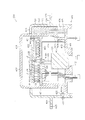
以下、パチンコ遊技機(以下、単に「パチンコ機」という)の一実施形態を、図面に基づいて詳細に説明する。ここで、図1はパチンコ機10の正面図であり、図2は斜視図であり、図3は内枠12及び前面枠セット14を開放した状態を示す斜視図である。図4は内枠12及び遊技盤30等の構成を示す正面図である。図5はパチンコ機10の背面図であり、図6は内枠12及び裏パックユニット203等を開放した状態を示す斜視図である。但し、図3では便宜上、遊技盤30面上に配設される釘や役物、前面枠セット14に取付けられるガラスユニット137等を省略して示している。
Hereinafter, an embodiment of a pachinko gaming machine (hereinafter simply referred to as “pachinko machine”) will be described in detail with reference to the drawings. Here, FIG. 1 is a front view of the
図3等に示すように、パチンコ機10は、当該パチンコ機10の外郭を構成する外枠11を備えており、この外枠11の一側部に内枠12が開閉可能に支持されている。
As shown in FIG. 3 and the like, the
外枠11は、図6等に示すように、上辺枠構成部11a及び下辺枠構成部11bが木製の板材により構成され、左辺枠構成部11c及び右辺枠構成部11dがアルミニウム合金製の押出成形材により構成され、これら各枠構成部11a〜11dがネジ等の離脱可能な締結具により全体として矩形枠状に組み付けられている。
As shown in FIG. 6 and the like, the
左辺枠構成部11cの上下端部には、それぞれ上ヒンジ81及び下ヒンジ82が取着されている(図1参照)。当該上ヒンジ81及び下ヒンジ82にて、内枠12の上下部が回動可能に支持されており、これにより内枠12が開閉可能となる。そして、外枠11の内側に形成される空間部に内枠12等が収容される。
An
また、右辺枠構成部11dには、その幅方向後端部近傍から外枠11内側へ向け突出した延出壁部83が形成されている。延出壁部83は、内枠12の右側部背面側に設けられる施錠装置600(図6参照)に対応する上下区間全域を内枠12の背面側から覆っている(図5参照)。加えて、図3に示すように、延出壁部83の前面側には、施錠装置600の係止部材が係止される上下一対の受部84,85が設けられている。また、下側の受部85には、後述する内枠開放検知スイッチ92に当接する押圧部86が、外枠11内側に向けて突設されている。
The right side
さらに、下辺枠構成部11bには樹脂製の幕板飾り87が取着されている。幕板飾り87の上面奥部には、上方に突出するリブ88が一体形成されている。これにより内枠12との間に隙間が形成されにくくなっている。
Furthermore, a
図3に示すように、内枠12の開閉軸線は、パチンコ機10の正面からみて左側において上下に沿って設定されており、この開閉軸線を軸心として内枠12が前方側に開放できるようになっている。内枠12は、外形が矩形状をなす樹脂ベース38を主体に構成されており、当該樹脂ベース38の中央部には略楕円形状の窓孔39が形成されている。
As shown in FIG. 3, the opening / closing axis of the
また、内枠12の前面側には前面枠セット14が開閉可能に取付けられている。前面枠セット14は、内枠12と同様に、パチンコ機10の正面から見て左側において上下に沿って設定された開閉軸線を軸心として前方側に開放できるようになっている。
A
前面枠セット14は、内枠12と同様に外形が矩形状をなし、閉鎖状態においては内枠12の前面側ほぼ全域を覆う。前面枠セット14の中央部には略楕円形状の窓部101が形成されている。これにより、前面枠セット14の窓部101及び内枠12の窓孔39を介して、内枠12の後面に装着される遊技盤30(遊技領域)を外部から視認可能となる。遊技盤30の詳細な構成については後述する。
The
図1に示すように、前面枠セット14の前面側には、その下部中央において球受皿としての下皿15が設けられており、排出口16より排出された遊技球が下皿15内に貯留可能になっている。また、下皿15の手前側には、下皿15内から遊技球を排出するための球抜きレバー25が設けられている。加えて、下皿15の左部には、LEDが内蔵された演出ボタン125が設けられており、演出ボタン125を押圧操作することで、後述する装飾図柄表示装置42等において対応する演出が行われたり、演出内容が変更されたりする。
As shown in FIG. 1, on the front side of the front frame set 14, a
下皿15の右方には、手前側に突出した遊技球発射ハンドル(以下、単にハンドルという)18が設けられている。尚、ハンドル18には、図示しないタッチセンサや、ハンドル18の操作部の操作量を検出するための図示しない操作量検出手段が設けられている。
On the right side of the
下皿15の上方には上皿19が設けられている。上皿19は、遊技球を一旦貯留し、一列に整列させながら後述する発射手段としての遊技球発射装置(以下、単に発射装置という)60の方へ案内する球受皿である。尚、上皿19が遊技球で満杯になった状態では、払出される遊技球は、後述する下皿連通路71及び排出口16を介して、下皿15へと案内される。
An
上皿19には球貸しボタン121と返却ボタン122とが設けられている。これにより、遊技ホール等において、パチンコ機10の側方に配置されるカードユニット(球貸しユニット)に紙幣やカード等を投入した状態で球貸しボタン121が操作されると、その操作に応じて貸出球が上皿19に供給される。一方、返却ボタン122は、カードユニットに挿入されたカード等の返却を求める際に操作される。但し、カードユニットを介さずに球貸し装置等から上皿19に遊技球が直接貸し出されるパチンコ機、いわゆる現金機では球貸しボタン121及び返却ボタン122は不要である。
The
さらに、上皿19には、球抜きボタン123が設けられている。球抜きボタン123が押圧操作されることで、上皿19の球案内路の下流側に設けられ、下皿15に連通する連通孔(図示略)が開口し、上皿19に貯留されていた遊技球が下皿15へと案内される(落下する)。つまり、遊技者は、球抜きボタン123を操作することで、上皿19にある遊技球をいつでも下皿15に移すことができる。
Further, the
また、前面枠セット14の前面にはその周囲に各種ランプ等の発光手段が設けられている。これら発光手段は、大当たり時や所定のリーチ時等における遊技状態の変化に応じて点灯、点滅といった発光態様が変更制御され遊技中の演出効果を高める役割を果たすものである。例えば、窓部101の周縁には、LED等の発光手段を内蔵した環状電飾部102が設けられている。また、該環状電飾部102の両側部には、所定のエラー時に点灯するエラー表示ランプ104が設けられている。尚、環状電飾部102のうち各エラー表示ランプ104の上方部位には、前面枠セット14の背面に設けられるスピーカSP(図3参照)に対応して細かな透孔が多数形成されている。
In addition, light emitting means such as various lamps are provided around the front surface of the front frame set 14. These light emitting means play a role of enhancing the effect of the game during the game by changing and controlling the light emission mode such as lighting and blinking according to the change of the game state at the time of big hit or predetermined reach. For example, at the periphery of the
前面枠セット14の背面側にはガラスユニット137が取付けられている。ガラスユニット137は、従来の前後一対の矩形状の板ガラスが前後対をなして別々に取着されるものではなく、全体として丸形をなし、アッセンブリ化された上で取付けられている。
A
次に、内枠12(樹脂ベース38)について図4を参照して説明する。上述した通り、内枠12(樹脂ベース38)には、窓孔39の後側において遊技盤30が装着されている。遊技盤30は、その周縁部が内枠12(樹脂ベース38)の裏側に当接した状態で取着されている。従って、遊技盤30の前面部の略中央部分が樹脂ベース38の窓孔39を通じて内枠12の前面側に露出した状態となっている。
Next, the inner frame 12 (resin base 38) will be described with reference to FIG. As described above, the
また、内枠12(樹脂ベース38)の前面下部、すなわち窓孔39(遊技盤30)の下方位置には、発射装置60及び当該発射装置60より発射された直後の遊技球を案内する発射レール61が取付けられている。本実施形態では、発射装置60としてソレノイド式発射装置を採用している。また、発射装置60の上方には、上皿19から案内される遊技球を、内蔵された駆動手段(例えばソレノイド)の駆動により、1球ずつ発射装置60の発射位置へと案内する球送り装置63が設けられている。
Further, at the lower part of the front surface of the inner frame 12 (resin base 38), that is, below the window hole 39 (game board 30), a launch rail for guiding the
次に、遊技盤30の構成について図4を参照して説明する。遊技盤30には、一般入賞口31、可変入賞装置32、第1契機対応ユニット(始動口)33、第2契機対応口34、可変表示装置ユニット35等がルータ加工によって形成された貫通孔に配設され、遊技盤30前面側から木ネジ等により取付けられている。周知の通り一般入賞口31、可変入賞装置32、第1契機対応ユニット33などの各種入賞口に遊技球が入球(入賞)すると、各種検出スイッチにより検出され、上皿19(又は下皿15)へ所定数の賞球が払い出される。例えば、第1契機対応ユニット33への入球があった場合には3個、一般入賞口31への入球があった場合には10個、可変入賞装置32への入球があった場合には15個の遊技球が上皿19(下皿15)に払出される。その他に、遊技盤30にはアウト口36が設けられており、一般入賞口31等の各種入賞口に入賞しなかった遊技球は、このアウト口36を通って遊技領域外へと排出される。また、遊技盤30には、遊技球の落下方向を適宜分散、調整等するために多数の釘が植設されているとともに、風車等の各種部材(役物)が配設されている
第1契機対応ユニット33は、遊技領域を流下する遊技球が入球可能な上入賞口33a及び下入賞口33bと、下入賞口33bの両側部に設けられた開閉する一対の開閉部材33cを備えている。上入賞口33aは、遊技球が常時入球可能となっているのに対し、下入賞口33bは、開閉部材33cが所定条件の成立に応じて開閉動作することにより、遊技領域を流下する遊技球が入球可能な開状態と、遊技球が入球不可能な閉状態との間で状態変化可能に構成されている。尚、詳しくは後述するが、第1契機対応ユニット33は、上入賞口33a、下入賞口33bに入球した遊技球をそれぞれ検知する第1契機対応スイッチ224a、224bを備えており、当該第1契機対応スイッチ224a、224bにて遊技球が検知された場合に、大当たり状態を発生させるか否かの当否抽選が行われるとともに、特別表示装置43及び装飾図柄表示装置42にて変動表示が行われる構成となっている。そして、当否抽選にて当選した場合には、大当たり状態(特別遊技状態)が付与される。
Next, the configuration of the
また、第2契機対応口34は、遊技領域を流下する遊技球が1球ずつ通過可能に構成されている。詳しくは後述するが、第2契機対応口34は、当該第2契機対応口34を通過する遊技球を検知可能な第2契機対応スイッチ225を備えており、当該第2契機対応スイッチ225にて遊技球が検知された場合に、第1契機対応ユニット33を開状態とするか否かの開放抽選が行われるとともに、普通図柄表示装置41にて変動表示が行われる構成となっている。そして、開放抽選にて当選した場合には、第1契機対応ユニット33が規定時間だけ開状態とされる。
Further, the second opportunity corresponding port 34 is configured so that game balls flowing down the game area can pass one by one. As will be described in detail later, the second opportunity corresponding port 34 includes a second
可変表示装置ユニット35には、第2契機対応口34の通過を契機として変動表示する普通図柄表示装置41と、第1契機対応ユニット33(上入賞口33a又は下入賞口33b)への入賞を契機として変動表示する特別表示装置43と、特別表示装置43による変動表示に合わせて変動表示する装飾図柄表示装置42とが設けられている。
The variable
普通図柄表示装置41は、普通図柄として「○」又は「×」を点灯表示可能に構成されており、遊技球が第2契機対応口34を通過する毎に例えば普通図柄を「○」→「×」→「○」→・・・という具合に高速で切換表示(変動表示)する。そして、その変動表示が「○」図柄(当選図柄)で数秒間停止した場合には、第1契機対応ユニット33が所定時間だけ開状態となる。この普通図柄表示装置41は、後述する主制御装置261によって直接的に表示内容が制御される。
The normal
また、普通図柄表示装置41の変動表示中に、新たに遊技球が第2契機対応口34を通過した場合には、その分の変動表示は、その時点で行われている変動表示の終了後に行われる構成となっている。つまり、変動表示が待機(保留)されることとなる。この保留される変動表示の最大回数は、パチンコ機の機種毎に決められているが、本実施形態では4回まで保留され、その保留回数が保留ランプ44にて点灯表示されるようになっている。
In addition, when the game ball newly passes through the second opportunity corresponding port 34 during the fluctuation display of the normal
特別表示装置43は、普通図柄表示装置41の右側方に設けられ、赤、緑、青の発光色を有する三色発光ダイオード(三色LED)により構成されている。そして、遊技球が第1契機対応ユニット33に入賞する毎に色換え表示(変動表示)が行われ、変動表示が停止したときの点灯態様(点灯色)により、大当たりか否かが確定的に表示される。
The
より詳しくは、第1契機対応ユニット33に対し遊技球が入賞すると、特別表示装置43は、3色LEDを赤→緑→青→赤→・・・という具合に高速で色換え表示(変動表示)し、所定時間が経過すると、いずれかの色に決定表示する。高速の色換え表示とは、例えば4msec毎に赤、緑、青を順番に表示するという具合である。大当たり抽選に当選した場合には、この際、赤又は緑で決定表示(例えば数秒間停止)され、特別遊技状態が発生する。特に、赤は、大当たり終了後の遊技モードが高確率モードであることを示す表示であり、緑は、大当たり終了後の遊技モードが時間短縮モードであることを示す表示である。なお、この特別表示装置43についても、主制御装置261によって表示内容が直接的に制御される。
More specifically, when the game ball wins the first
また、特別表示装置43の変動表示中に新たに遊技球が第1契機対応ユニット33に入賞した場合には、その分の変動表示は、その時点で行われている変動表示の終了後に行われる構成となっている。つまり、変動表示が待機(保留)されることとなる。この保留される変動表示の最大回数は、パチンコ機の機種毎に決められているが、本実施形態では4回まで保留され、その保留回数が保留ランプ46にて点灯表示されるようになっている。また、大当たり状態中に新たに遊技球が第1契機対応ユニット33に入賞した場合、その分の変動表示についても保留される。
Further, when a new game ball wins the first
装飾図柄表示装置42は液晶表示装置として構成されており、後述するサブ制御装置262及び表示制御装置45によって表示内容が制御される。すなわち、装飾図柄表示装置42においては、特別表示装置43にて表示される結果に対応させるように、主制御装置261からのコマンドに基づき、サブ制御装置262によって補助的な表示内容が決定され、後述する表示制御装置45によって表示が行われる。
The decorative
装飾図柄表示装置42には、例えば、上、中及び下の3つの図柄表示領域が設けられ、各図柄表示領域において複数種類の図柄(数字)が順次表示され(変動表示され)、その後、図柄表示領域毎に順番に(例えば、上図柄表示領域→下図柄表示領域→中図柄表示領域の順に)図柄が停止表示されるようになっている。例えば、主制御装置261にて大当たりが確定すると、特別表示装置43にて大当たりに対応する表示がなされるとともに、装飾図柄表示装置42にて図柄が大当たりに対応する組合わせで停止表示され(例えば、上図柄表示領域、中図柄表示領域、及び下図柄表示領域にて停止表示される図柄が同一となり)、大当たり状態が開始される。
The decorative
また、図柄が大当たりに対応する組合わせで停止表示される場合には、その前段階として、例えば、上図柄表示領域及び下図柄表示領域において同一の図柄が停止表示されることとなる。このように上図柄表示領域及び下図柄表示領域にて同一図柄が停止表示されるとともに、中図柄表示領域において未だ変動表示が行われている状態がリーチ状態である。 Further, when symbols are stopped and displayed in combinations corresponding to jackpots, the same symbol is stopped and displayed in the upper symbol display area and the lower symbol display area, for example, as a preceding stage. In this way, the state where the same symbol is stopped and displayed in the upper symbol display area and the lower symbol display area and the variable display is still being performed in the middle symbol display area is the reach state.
また、可変表示装置ユニット35には、装飾図柄表示装置42を囲むようにしてセンターフレーム47が配設されている。センターフレーム47の上部には入球口151が設けられており、該入球口151に入球した遊技球は、センターフレーム47の内部に形成され、装飾図柄表示装置42の側部に沿って上下に延びるワープ流路152を介して、装飾図柄表示装置42の下方に形成されたステージ153上に案内される。ステージ153上に案内された遊技球は、ステージ153上から前方の遊技領域に転落したり、ステージ153上を転動した後ステージ153の中央奥側に形成されたポケット154に入球したりする。尚、ポケット154は、第1契機対応ユニット33の直上方の遊技領域へと通じる案内通路155と連通しており、該ポケット154に入球した遊技球は、比較的高い確率で第1契機対応ユニット33に入球するようになっている。
The variable
可変入賞装置32は、通常は遊技球が入賞できない閉状態になっており、大当たり(特別遊技状態の発生)の際に、遊技球が入賞可能な開状態とされる。具体的には、規定時間(例えば30秒)の経過又は規定個数(例えば8個)の入賞を1ラウンドとして、可変入賞装置32の大入賞口が所定回数(所定ラウンド数)繰り返し開放される。
The
また、遊技盤30には、内レール構成部51と外レール構成部52とからなり、発射装置60から発射された遊技球を遊技盤30上部へ案内するレール50が取付けられている。これにより、ハンドル18の回動操作に伴い発射された遊技球は発射レール61及びレール50を通じて、遊技盤30とガラスユニット137との間に形成される遊技領域内に案内される。
The
内レール構成部51の先端部分(図4の左上部)には戻り球防止部材53が取着されている。これにより、一旦、レール50から遊技領域へと案内された遊技球が再度レール50内に戻ってしまうといった事態が防止される。
A return ball preventing member 53 is attached to the tip portion of the inner rail constituting portion 51 (the upper left portion in FIG. 4). This prevents a situation in which the game ball once guided from the
また、本実施形態では、外レール構成部52が遊技盤30の右上部で途絶え、内レール構成部51が遊技盤30の右下部で途絶えている。このため、遊技領域は、レール50及び樹脂ベース38の窓孔39の内周面により画定される。但し、発射装置60にて打出された遊技球が、戻り球防止部材53を通過するまでは、レール50を逆流する場合があるため、内外レール構成部51,52の並行部分は遊技領域から除かれる。
In the present embodiment, the outer rail component 52 is interrupted at the upper right portion of the
図3に示すように、前面枠セット14の背面側には、窓部101の下方において、球通路ユニット70が設けられている。球通路ユニット70は、後述する払出機構部352から下皿15の排出口16へ繋がる下皿連通路71と、払出機構部352から上皿19へ繋がる上皿連通路73と備えている。また、内枠12に設けられた発射レール61とレールユニット50(外レール構成部52)との間には所定間隔の隙間があり、球通路ユニット70には、前記隙間より落下した遊技球を下皿15へと案内するファール球通路72が形成されている。これにより、仮に、発射装置60から発射された遊技球が戻り球防止部材53まで至らずファール球としてレール50を逆戻りする場合には、そのファール球がファール球通路72を介して下皿15に排出される。
As shown in FIG. 3, a
また、図3及び図4中の符号67は後述する払出機構部352により払出された遊技球を内枠12の前方に案内するための払出通路であり、上皿連通路73(上皿19)に通じる通路と、下皿連通路71(下皿15)に通じる通路とに分かれている。払出通路67の下方にはシャッタ68が設けられており、前面枠セット14を開放した状態では、バネ等の付勢力によりシャッタ68が前方に突出して払出通路67の出口をほぼ閉鎖するようになっている。また、前面枠セット14を閉じた状態では、下皿連通路71の入口側後端部によってシャッタ68が押し開けられるようになっている。尚、下皿連通路71及び上皿連通路73の入口(球流入部)が隣接するとともに、前面枠セット14の閉状態において当該各入口と払出通路67とが所定距離だけ離間しており、両者間の隙間を遊技球が通過可能となっている。このため、上皿19及び上皿連通路73が遊技球で満杯となると、払出される遊技球が下皿連通路71側に流れ(下皿連通路71の入口側に溢れ)、下皿連通路71を通って下皿15に払出されることとなる。
3 and 4 is a payout passage for guiding a game ball paid out by a
加えて、球通路ユニット70には、下皿連通路71内に位置する遊技球を検知する満杯検知スイッチ(図示略)が設けられている。当該満杯検知スイッチの存在により、下皿15が遊技球で満杯になっていること(下皿15が遊技球で満杯となり、下皿連通路71において遊技球が滞留していること)を把握することができる。本実施形態では、満杯検知スイッチによって所定時間継続して遊技球が検知されることに基づき、発射装置60の打出しを禁止するといった制御が行われる。尚、下皿連通路71における遊技球の滞留が解消され、満杯検知スイッチにより遊技球が検知されなくなると(所定時間継続して検知されなくなると)発射装置60の打出しが許容される。
In addition, the
次に、パチンコ機10の背面構成について図5、図6等を参照して説明する。パチンコ機10の背面には、各種制御基板が上下左右に並べられるようにして、一部前後に重ねられるようにして配置されており、さらに、遊技球を供給する遊技球供給装置(払出機構)や樹脂製の保護カバー等が取り付けられている。払出機構及び保護カバーは1ユニットとして一体化されており、一般に樹脂部分を裏パックと称することもあるため、ここではそのユニットを「裏パックユニット203」と称する。
Next, the back configuration of the
まず、遊技盤30の背面構成について説明する。図6に示すように、遊技盤30中央の貫通孔に対応して配設された可変表示装置ユニット35(図4参照)の背面側には、センターフレーム47を背後から覆う樹脂製のフレームカバー213が後方に突出して設けられている。また、フレームカバー213の背面側には、フレームカバー213の開口部から前方に臨む液晶表示装置たる装飾図柄表示装置42、表示制御装置45及びサブ制御装置262が前後に重ねられた状態で着脱可能に取り付けられている。
First, the back configuration of the
装飾図柄表示装置42は、当該装飾図柄表示装置42の表示部(液晶画面)をパチンコ機10の前面側に露出させるための開口部が形成された収容ボックス42aに収容されてフレームカバー213の背面側に固定されている。表示制御装置45は基板ボックス45aに収容されて装飾図柄表示装置42(収容ボックス42a)の背面側に固定されている。サブ制御装置262は基板ボックス262aに収容されて表示制御装置45(基板ボックス45a)の背面側に固定されている。尚、フレームカバー213内には、センターフレーム47に内蔵されたLED等を駆動するLED制御基板等が配設されている。また、収容ボックス42a及び基板ボックス45a,262aは透明樹脂材料等により構成され、内部が視認可能となっている。
The decorative
フレームカバー213の下方には裏枠セット215が、一般入賞口31、可変入賞装置32及び第1契機対応ユニット33等を背後から覆うようにして遊技盤30に取付けられている。裏枠セット215は、各種入賞口に入賞した遊技球を回収するための球回収機構を備えている(図示略)。この球回収機構により回収された遊技球は、後述する排出通路部217に案内され、排出通路部217の排出シュートからパチンコ機10外部に排出される。
Under the
また、本実施形態では、裏枠セット215が主制御装置261の取付台として機能する。より詳しくは、主制御装置261を搭載した基板搭載ユニット260が、裏枠セット215に対し回動可能に軸支され、後方に開放可能となっている。
In the present embodiment, the back frame set 215 functions as a mounting base for the
主制御装置261は透明樹脂材料等よりなる基板ボックス263に収容されている。基板ボックス263は、ボックスベースと該ボックスベースの開口部を覆うボックスカバーとを備え、これらボックスベースとボックスカバーとが封印部材によって連結されている。封印部材によって連結された基板ボックス263は、所定の痕跡を残さなければ開封できない構成となっている。これにより、基板ボックス263が不正に開封された旨を容易に発見することができる。
The
また、遊技盤30には、入球手段としての一般入賞口31等の各種入賞口に対応して、当該各種入賞口へ入球した遊技球を検出する入球検出スイッチ(入球検出手段)が設けられている。具体的には、図4に示すように、一般入賞口31に対応する位置には入賞口スイッチ221が設けられ、可変入賞装置32にはカウントスイッチ223が設けられている。また、第1契機対応ユニット33には、上入賞口33a及び下入賞口33bそれぞれに対応して第1契機対応ユニットスイッチ224a,224bが設けられている。さらに、第2契機対応口34に対応する位置には第2契機対応口スイッチ225が設けられている。
In addition, the
また、図示は省略するが、裏枠セット215には、入賞口スイッチ221、カウントスイッチ223及び第2契機対応口スイッチ225とケーブルコネクタを介して電気的に接続される第1盤面中継基板が設けられている。この第1盤面中継基板は、入賞口スイッチ221等と、制御手段としての主制御装置261とを中継するものであり、ケーブルコネクタを介して主制御装置261と電気的に接続されている。
Although not shown, the back frame set 215 is provided with a first board surface relay board that is electrically connected to the
これに対し、第1契機対応ユニット33(上入賞口33a又は下入賞口33b)への入球を検出する第1契機対応スイッチ224a,224bは中継基板を経ることなくコネクタケーブルを介して直接主制御装置261に接続されている。
On the other hand, the first opportunity corresponding switches 224a and 224b that detect the entry into the first opportunity corresponding unit 33 (the upper winning opening 33a or the lower winning opening 33b) are directly connected via the connector cable without passing through the relay board. It is connected to the
各種入球検出スイッチにて各々検出された検出結果は、主制御装置261に取り込まれる。そして、該主制御装置261よりその都度の入賞状況に応じた払出指令(遊技球の払出個数)が払出制御装置311に送信され、該払出制御装置311からの出力信号に基づき所定数の遊技球の払出しが実施される(第2契機対応スイッチ225により検出された場合を除く。)
この他、遊技盤30の裏面には、図示は省略するが、可変入賞装置32にて大入賞口を開放する大入賞口用ソレノイドが設けられ、第1契機対応ユニット33にて一対の開閉部材33cを開閉駆動する入賞口用ソレノイドが設けられている。また、裏枠セット215には、これらソレノイドと主制御装置261とを中継する第2盤面中継基板(図示略)も設けられている。
The detection results detected by the various entrance detection switches are taken into the
In addition, although not shown in the drawings, the back of the
次に、裏パックユニット203の構成を説明する。図5に示すように、裏パックユニット203は、樹脂成形された裏パック351と、遊技球の払出機構部352とを一体化したものである。また、裏パックユニット203は、内枠12の左側部(図5では右側)に対して開閉可能に支持されており、上下方向に沿って延びる開閉軸線を軸心として後方に開放できるようになっている。加えて、裏パックユニット203の左上部(図5では右上部)には外部中継端子板240が設けられている。
Next, the configuration of the
外部中継端子板240は、遊技ホールのホールコンピュータなどへの各種情報送信を中継するためのものであり、複数の外部接続端子が設けられている。便宜上、符号は付さないが、例えば現在の遊技状態(大当たり状態や高確率状態等)に関する情報を出力するための端子、後述する開放検知スイッチ91,92によって検出される前面枠セット14や内枠12の開放に関する情報を出力するための端子、入球エラー、下皿満タンエラー、タンク球無しエラー、払出しエラーなど各種エラー状態に関する情報を出力するための端子、払出制御装置311から払出される賞球数に関する情報を出力するための端子などが設けられている。
The external
裏パック351は例えばABS樹脂により一体成形されており、パチンコ機10の後方に突出して略直方体形状をなす保護カバー部354を備えている。保護カバー部354は左右側面及び上面が閉塞され且つ下面のみが開放された形状をなし、少なくともフレームカバー213を覆うのに十分な大きさを有する。但し、本実施形態では、保護カバー部354が基板搭載ユニット260の上部及び右部(図5では左側の部位)も合わせて覆う構成となっている。これにより、裏パックユニット203の閉鎖状態において、基板ボックス263の右部に設けられた封印部材、及び主制御装置261の上縁部に沿って設けられた端子部(基板側コネクタ)が覆われることとなる。
The
払出機構部352は、保護カバー部354を迂回するようにして配設されている。すなわち、保護カバー部354の上方には、上側に開口したタンク355が設けられており、このタンク355には遊技ホールの島設備から供給される遊技球が逐次補給される。タンク355の下方には、例えば横方向2列の球通路を有し下流側に向けて緩やかに傾斜するタンクレール356が連結され、さらにタンクレール356の下流側には縦向きにケースレール357が連結されている。払出装置358はケースレール357の最下流部に設けられ、払出モータ等の所定の電気的構成により必要個数の遊技球の払出が適宜行われる。そして、払出装置358より払出された遊技球は上皿19等に供給される。
The
また、払出機構部352には、払出制御装置311から払出装置358への払出指令の信号を中継する払出中継基板381が設置されると共に、外部より主電源を取り込む電源スイッチ基板382が設置されている。電源スイッチ基板382には、電圧変換器を介して例えば交流24Vの主電源が供給され、電源スイッチ382aの切替操作により電源ON又は電源OFFされる。
The
裏パックユニット203(基板搭載ユニット260)の下方には、内枠12の左側部(図5では右側)にて軸支され、後方に開放可能な下枠セット251が設けられている。図6に示すように、下枠セット251には、上述した球回収機構により回収された遊技球が流入する排出通路部217が形成され、排出通路部217の最下流部には、遊技球をパチンコ機10外部へ排出する排出シュート(図示略)が形成されている。つまり、一般入賞口31等の各入賞口に入賞した遊技球は、裏枠セット215の球回収機構を介して集合し、さらに排出通路部217の排出シュートを通じてパチンコ機10外部に排出される。なお、アウト口36も同様に排出通路部217に通じており、何れの入賞口にも入賞しなかった遊技球も排出シュートを介してパチンコ機10外部に排出される。尚、本実施形態では、裏パックユニット203と下枠セット251とが別体として構成され、それぞれ独立して開閉可能であるが、裏パックユニット203と下枠セット251とが一体的に形成されることとしてもよい。
Below the back pack unit 203 (substrate mounting unit 260), there is provided a lower frame set 251 that is pivotally supported on the left side of the inner frame 12 (right side in FIG. 5) and can be opened rearward. As shown in FIG. 6, the lower frame set 251 is formed with a
また、図5に示すように、下枠セット251の背面側には、払出制御装置311、発射制御装置312、電源装置313及びカードユニット接続基板314が前後に重ねられた状態で着脱可能に取り付けられている。
Further, as shown in FIG. 5, the
発射制御装置312及び電源装置313は基板ボックス313aに収容されて下枠セット251の背面側に固定されている。尚、発射制御装置312及び電源装置313は、便宜上それぞれ独立した制御装置として説明するが、実際には1つの基板(プリント基板)により構成される。
The
また、払出制御装置311は、基板ボックス311aに収容されて、基板ボックス313a(発射制御装置312及び電源装置313)の背面側に固定されている。尚、払出制御装置311が収容される基板ボックス311aには、上述した主制御装置261が収容される基板ボックス263と同様に封印部材が設けられ、基板ボックス311aの開封された痕跡が残るようになっている。
The
加えて、カードユニット接続基板314は、基板ボックス314aに収容されて、基板ボックス313a(発射制御装置312及び電源装置313)の背面側に固定されている。
In addition, the card
なお、上記各基板ボックス311a,313a,314aは透明樹脂材料等により構成されており、内部が視認可能となっている。
Each of the
また、払出制御装置311には基板ボックス311aから外方に突出する状態復帰スイッチ321が設けられている。例えば、払出モータ部の球詰まり等、払出エラーの発生時において状態復帰スイッチ321が押下されると、払出モータが正逆回転され、球詰まりの解消(正常状態への復帰)が図られる。
Further, the dispensing
さらに、電源装置313には基板ボックス313aから外方に突出するRAM消去スイッチ323が設けられている。本パチンコ機10はバックアップ機能を有しており、万一停電が発生した際でも停電時の状態を保持し、停電からの復帰(復電)の際には停電時の状態に復帰させることができる。従って、通常手順で(例えば遊技ホールの営業終了時に)電源遮断すると電源遮断前の状態が記憶保持されることから、電源投入時に初期状態に戻したい場合には、RAM消去スイッチ323を押しながら電源を投入する。
Further, the
また、図6に示すように、内枠12の右側部背面側には施錠装置600が設けられている。施錠装置600は、前面枠セット14の前面側に露出するシリンダ錠700(図1等参照)を備えており、該シリンダ錠700の鍵穴に鍵を挿入し、一方に回動操作することで内枠12を解錠でき、他方に回動操作することで前面枠セット14を解錠できるようになっている。本実施形態では、内枠12は外枠11に対し施錠され、前面枠セット14は内枠12に対し施錠される。
As shown in FIG. 6, a
尚、上記のように、外枠11の右辺枠構成部11dには、施錠装置600に対応する上下区間全域を内枠12の背面側から覆う延出壁部83が形成されている(図5参照)。これにより、外枠11の背面側から線材等を進入させ、当該線材等により施錠装置600を操作することが困難となる。結果として、防御性能の向上を図ることができる。さらに、延出壁部83は、裏パックユニット203及び下枠セット251の右端部(図5では左側の端部)を背面側から覆う構成となっており、内枠12の閉状態においては、裏パックユニット203及び下枠セット251を開放できない構成となっている。
In addition, as described above, the extending
また、図4に示すように、内枠12の前面側右下部(発射装置60の右側)には、前面枠セット14の開放を検知するための前面枠開放検知スイッチ91が設けられ、図5に示すように、内枠12の背面側右下部(図5では左下)には、内枠12の開放を検知するための内枠開放検知スイッチ92が設けられている。前面枠開放検知スイッチ91及び内枠開放検知スイッチ92は、それぞれスイッチ本体部に対して出没可能な検知部を備えており、前面枠開放検知スイッチ91は検知部が前方に向くように設けられ、内枠開放検知スイッチ92は検知部が後方へ向くように設けられる。そして、検知部がスイッチ本体部から突出した状態にある場合にはオン信号を主制御装置261に出力し、検知部がスイッチ本体部側に押圧され、スイッチ本体部に没入した状態ではオフ信号を主制御装置261に出力する構成となっている。つまり、前面枠開放検知スイッチ91は前面枠セット14の閉鎖時において検知部が前面枠セット14の背面で押圧されてオフ状態となり、前面枠セット14の開放時には、検知部が突出状態に戻ってオン状態となる。同様に、内枠開放検知スイッチ92は内枠12の閉鎖時において検知部が外枠11の受部85に一体形成された押圧部86によって押圧されてオフ状態となり、内枠12の開放時には検知部が突出状態に戻ってオン状態となる。
As shown in FIG. 4, a front frame
さて、本実施形態では、演出ボタン125に特徴がある。以下、演出ボタン125の構成について図7〜図9を参照して詳細に説明する。本実施形態では、演出ボタン125が電飾手段、操作手段に相当する。尚、図7は演出ボタン125を示す模式断面図である。図8(a)は上基板402を示す上面図であり、図8(b)は下基板403を示す上面図であり、図8(c)は支持金具451を示す断面図である。図9は演出ボタン125の回路構成を説明するための図である。尚、前面枠セット14(下皿15を構成する下皿ユニット)のうち演出ボタン125が取付けられる部位は前方に向けて若干下方傾斜しており、従って、演出ボタン125も若干傾いて取付けられるのではあるが、便宜上、演出ボタン125が単に上向きに取付けられているものとして説明する。
In the present embodiment, the
図7等に示すように、演出ボタン125は、前面枠セット14に固定される本体部401と、3つの発光手段L1、L2、L3が搭載された発光体ブロックとしての上基板402と、上基板402の下方において上基板402と対向配置される接続ブロックとしての下基板403と、透明又は半透明な素材よりなり、上基板402の上方を覆うカバー部材としての操作部404と、上基板402を回転させる駆動手段としてのモータ405と、操作部404を上方に付勢する付勢手段としてのコイルばね406と、操作部404の操作を検知する操作検知手段としての操作検知スイッチ407とを備えている。
As shown in FIG. 7 and the like, the
本体部401は、モータ405が搭載されるベース板411と、ベース板411とは別体として構成される略円筒状の枠体421とを備えている。
The
ベース板411は、略円盤状に構成され、中央部においてモータ405の下部を嵌合するモータ設置部412が形成された土台部413と、モータ設置部412を囲むようにして土台部413から上方に突出し、下基板403の外周部を支持する支持壁部414と、コイルばね406の下部を支持するばね支持部415とを備えている。
The
支持壁部414は、下基板403を土台部413から所定距離だけ上方に離間した位置で支持するために設けられた壁部である。本実施形態における支持壁部414は、下基板403の外周形状(円形状)に合わせて断面略円弧状に形成された3つの壁部を下基板403の中央部を中心とした均等位置に設けることで構成されている(図8(b)参照)。支持壁部414の先端部は、下基板403の中央部側が一段低くなった段差形状をなしており、当該支持壁部414の先端部により、下基板403の外周部の下面及び外周面が支持される構成となっている。また、図8(b)の二点鎖線で示すように、支持壁部414の先端部には位置決め凸部417が形成されており、下基板403の設置に際し、下基板403の外周部に形成された位置決め凹部419が位置決め凸部417に嵌め込まれる。これにより、下基板403の位置決めが行われるとともに、下基板403の周方向への変位(回動変位)が規制される。
The
ばね支持部415は、土台部413から上方に突出する略円柱状の突起であり、土台部413の中央部を中心として均等位置に3つ設けられている。ばね支持部415に対してコイルばね406を挿通状態とすることで、コイルばね406の下部が支持されることとなる。
The
枠体421は、上下方向に延びる円筒状の基部422と、基部422の上側の開口部の周縁部を塞ぐようにして設けられる円環状の縁壁部423と、基部422の外周面から外方に突出する取付片424とを備えている。取付片424には、上下に貫通する取付孔425が形成されている。そして、取付孔425と、前面枠セット14(下皿15を構成する下皿ユニット)に形成されたねじ穴(図示略)とを位置合わせし、ねじ固定することで、演出ボタン125が前面枠セット14に取付けられている。
The
尚、ベース板411の土台部413の外周部は段差形状となっており、枠体421(基部422)の下側の開口部を塞ぐようにして、枠体421に対しベース板411を組付けると、当該段差部において枠体421(基部422)の下部が支持されるようになっている。また、土台部413の外周部には、上方に突出するねじ固定部420が、周方向に沿って所定間隔毎に(例えば5つ)設けられている。ねじ固定部420には、土台部413の遠心方向に沿って貫通するねじ孔420aが形成されている。そして、ベース板411と枠体421とを組付けた後、かかるねじ孔420aと、枠体421に形成された固定孔427とを位置合わせし、ねじ固定することで、枠体421がベース板411に取付けられている。また、ベース板411には、モータ405、下基板403、及び操作検知スイッチ407に接続された配線を挿通させるための開口が形成されている。
The outer peripheral portion of the
操作部404は、上下方向に延びる円筒状の周壁部431と、周壁部431の上側の開口部を閉塞する天壁部432と、周壁部431の外面側に設けられ、コイルばね406の上部を支持するばね収容部433とを備えている。周壁部431は、枠体421の縁壁部423を上下に貫通した状態となっており、天壁部432は枠体421から上方に突出している。
The
ばね収容部433は、周壁部431の上下方向中間位置から下端部にかけて上下に延び、下方が開放され、上方が閉塞された略筒状をなしている。また、ばね収容部433は、ベース板411の土台部413に設けられた3つのばね支持部415に対応して3つ設けられている。ばね収容部433の内側には、ばね支持部415及びコイルばね406が挿入状態とされており、これによって、コイルばね406の上部が支持されるとともに、操作部404の回動変位が規制される。すなわち、ばね支持部415とばね収容部433とによりコイルばね406の両端部を支持させるようにして、コイルばね406をベース板411と操作部404との間に介在させることにより、操作部404が上方に付勢されることとなる。尚、操作部404が押下操作されていない状態においては、コイルばね406の付勢力により、ばね収容部433の上面と、縁壁部423の下面とが当接状態とされるとともに、操作部404と土台部413とが上下に離間した状態となっている。また、ばね収容部433の外面は、枠体421の基部422の内面に略当接状態となっており、操作部404が上下に動作すると、ばね収容部433と基部422とが摺接するようになっている。これにより、操作部404の上下動がガイドされることとなる。
The spring
操作検知スイッチ407は、操作部404の周壁部431の内面側に設けられた操作側端子部435と、入出力ポート554に電気的に接続され、ベース板411の土台部413に設けられたベース側端子部436とから構成されている。操作部404が押下操作されていない状態においては、操作側端子部435とベース側端子部436とが離間し、操作部404が押下操作されると操作側端子部435とベース側端子部436とが接触する構成となっている。操作側端子部435とベース側端子部436とが接触することにより、操作側端子部435及びベース側端子部436を具備する回路が通電状態となり、操作部404の操作が検知される構成となっている。尚、操作検知スイッチ407の構成は特に限定されるものではなく、例えば、光センサ等を用いて操作部404の操作の検知を行うこととしてもよい。
The operation detection switch 407 is electrically connected to the operation
図8(a)に示すように、上基板402は略円盤状をなし、その上面には発光手段L1、L2、L3が上基板402の中央部を中心として均等位置に設置されている。発光手段L1、L2、L3は3色LEDにより構成され、それぞれ発光色が赤である発光素子(発光部)R1、R1、R1、発光色が緑である発光素子(発光部)G1、G2、G3、発光色が青である発光素子(発光部)B1、B2、B3を有している。また、図7に示すように、上基板402の下面には、発光手段L1、L2、L3(発光素子R1、R2、R3、G1、G2、G3、B1、B2、B3)と電気的に接続された発光側端子部P1〜P7が設けられている。本実施形態では、上基板402の外周側から内周側に向けて、P1→P2→P3→P4→P5→P6→P7の順に配設されている。また、本実施形態では、発光側端子部P1〜P7は、それぞれ複数の銅線がよられることで構成され、先端部が略ブラシ状になっている。さらに、本実施形態では、発光側端子部P1〜P7は、上基板402の遠心方向に沿った一直線上に並ぶようにして所定間隔毎に配置されている。つまり、上基板402の中心部と、各発光側端子部P1〜P7との間の距離がそれぞれ異なっており、上基板402が1回転する際に各発光側端子部P1〜P7の描く軌道がいずれも重ならないようになっている。尚、本実施形態では、説明の便宜上、発光側端子部P1〜P7が上基板402の遠心方向において一直線上に並ぶように配置されているが、特にこのような構成に限定されるものではなく、一直線上にではなく、点在させてもよい。尚、図8では、発光手段L1、L2、L3と発光側端子部P1〜P7とを電気的に接続するプリント配線(プリントパターン)の図示を省略している。
As shown in FIG. 8A, the
図9に基づいて、発光手段L1、L2、L3と、発光側端子部P1〜P7との対応関係を説明する。同図に示すように、発光素子R1のアノード側には発光側端子部P1が接続され、発光素子G1のアノード側には発光側端子部P2が接続され、発光素子B1のアノード側には発光側端子部P3が接続されている。また、発光素子R2、R3のアノード側には発光側端子部P4が接続され、発光素子G2、G3のアノード側には発光側端子部P5が接続され、発光素子B2、B3のアノード側には発光側端子部P6が接続されている。さらに、発光素子R1、R2、R3、G1、G2、G3、B1、B2、B3のカソード側には発光側端子部P7が接続されている。 Based on FIG. 9, the correspondence between the light emitting means L1, L2, and L3 and the light emitting side terminal portions P1 to P7 will be described. As shown in the figure, the light emitting side terminal portion P1 is connected to the anode side of the light emitting element R1, the light emitting side terminal portion P2 is connected to the anode side of the light emitting element G1, and the light emitting side is connected to the anode side of the light emitting element B1. The side terminal part P3 is connected. Further, the light emitting side terminal portion P4 is connected to the anode side of the light emitting elements R2 and R3, the light emitting side terminal portion P5 is connected to the anode side of the light emitting elements G2 and G3, and the anode side of the light emitting elements B2 and B3 is connected. The light emission side terminal part P6 is connected. Further, the light emitting side terminal portion P7 is connected to the cathode side of the light emitting elements R1, R2, R3, G1, G2, G3, B1, B2, and B3.
また、図7に示すように、上基板402の下面中央部には、上基板402と直交する方向に突出する連結部438が設けられている。連結部438は、下端部において後述するモータ405の回転軸461の先端部を挿入可能な筒状部438aを備えている。尚、詳しくは後述するモータ405の回転軸461の先端部は断面略D字状であり、筒状部438aの内側に形成される開口部の形状はこれに対応した形状となっている。これにより、筒状部438aに挿入された回転軸461の駆動力が確実に上基板402に伝達されることとなる。
As shown in FIG. 7, a connecting
図8(b)に示すように、下基板403は略円盤状をなしており、上記のように、外周部が支持壁部414により支持されている。下基板403の中央部には上下に貫通する挿通孔441が形成されており、当該挿通孔441には、上基板402の連結部438が挿通状態とされている。つまり、下基板403にモータ405の駆動力が伝達されることはなく、下基板403は本体部401に対して変位不可能に設けられている。
As shown in FIG. 8B, the
下基板403の上面には、上記各発光側端子部P1〜P7に個別に対応する本体側端子部Q1〜Q7が設けられている。図9に示すように、各本体側端子部Q1〜Q7はそれぞれ図示しないトランジスタ等のスイッチング素子や、抵抗、コンデンサ等を介して、音声やランプ等の制御を行うサブ制御装置262の入出力ポート554に接続されている。そして、サブ制御装置262は、入出力ポート554から信号を出力することによってスイッチング素子を駆動制御(オン、オフ)し、発光手段L1、L2、L3を点灯制御している。
On the upper surface of the
さて、本実施形態における本体側端子部Q1〜Q7は、下基板403の上面に形成されたプリント配線であり、上基板402を1回転させた場合に、対応する発光側端子部P1〜P7が描く軌道に沿って形成されている。つまり、上基板402を1回転させた場合に、7つの発光側端子部P1〜P7が描く軌道は、下基板403の中央部を中心とする7つの同心円であり、これらの同心円の円周上に沿って本体側端子部Q1〜Q7が延設されている。
The main body side terminal portions Q1 to Q7 in the present embodiment are printed wirings formed on the upper surface of the
具体的に、本体側端子部Q1〜Q7は、下基板403の外周側から内周側に向けて、Q1→Q2→Q3→Q4→Q5→Q6→Q7の順に配設されており、本体側端子部Q1は発光側端子部P1と接触可能に構成され、本体側端子部Q2は発光側端子部P2と接触可能に構成され、本体側端子部Q3は発光側端子部P3と接触可能に構成され、本体側端子部Q4は発光側端子部P4と接触可能に構成され、本体側端子部Q5は発光側端子部P5と接触可能に構成され、本体側端子部Q6は発光側端子部P6と接触可能に構成され、本体側端子部Q7は発光側端子部P7と接触可能に構成されている(図9参照)。そして、発光側端子部P1〜P7と本体側端子部Q1〜Q7との接触状態を保ちつつ、上基板402を下基板403に対して相対変位させることで、発光手段L1、L2、L3を点灯状態のまま下基板403に対して相対変位させることができる。
Specifically, the main body side terminal portions Q1 to Q7 are arranged in the order of Q1, Q2, Q3, Q4, Q5, Q6, and Q7 from the outer peripheral side to the inner peripheral side of the
また、本体側端子部Q4〜Q7は切れ目のない閉じた円環状となっており、上基板402の回転位相によらず、対応する発光側端子部P4〜P7と常時接触状態とされている。従って、発光側端子部P4〜P6、P7に接続される発光手段L2、L3の各発光素子R2、R3、G2、G3、B2、B3は、アノード側(本体側端子部Q4〜Q6)に接続された図示しないスイッチング素子がオンになるとともに、カソード側(本体側端子部Q7)に接続された図示しないスイッチング素子がオンになっていれば、上基板402がいかなる回転位相にあっても通電し、点灯することとなる。
Further, the main body side terminal portions Q4 to Q7 are formed in a closed annular shape without a break, and are always in contact with the corresponding light emitting side terminal portions P4 to P7 regardless of the rotational phase of the
一方、本体側端子部Q1〜Q3は周方向において一部が欠けた略C字状となっており、上基板402が回転することによって、対応する本体側端子部Q1〜Q3と接触している状態と、接触していない状態とに切替わることとなる。従って、発光側端子部P1〜P3、P7に接続される発光手段L1の各発光素子R1、G1、B1は、アノード側(本体側端子部Q1〜Q3)に接続された図示しないスイッチング素子がオンになるとともに、カソード側(本体側端子部Q7)に接続された図示しないスイッチング素子がオンになったとしても、上基板402の回転位相に応じて、点灯状態と消灯状態とに切替わることとなる。
On the other hand, the main body side terminal portions Q1 to Q3 are substantially C-shaped with a part missing in the circumferential direction, and are in contact with the corresponding main body side terminal portions Q1 to Q3 as the
本実施形態では、本体側端子部Q1、Q2、Q3毎に、下基板403の周方向において途切れている位置が異なっており、本体側端子部Q1は図8(b)の右方に開口し、本体側端子部Q2は同図の左下方に開口し、本体側端子部Q3は同図の左上方に開口したような形状となっている。より詳しくは、下基板403の遠心方向において、本体側端子部Q1〜Q3が重複する区間(図8(b)に示す区間a)が3箇所設けられ、その他の区間(図8(b)に示す区間b、c、d)では、本体側端子部Q1〜Q3のいずれか2つが重複している。
In the present embodiment, the positions where the main body side terminal portions Q1, Q2, Q3 are interrupted in the circumferential direction of the
また、本実施形態では、発光側端子部P1〜P7が上基板402の遠心方向に沿って一直線上に配置されているため、本体側端子部Q1〜Q3、Q7に接続された図示しないスイッチング素子がオンである場合に、発光側端子部P1〜P7が、図8(b)に示す区間aに位置すると発光手段L1の発光素子R1、G1、B1が点灯して発光色が白色となり、区間bに位置すると発光手段L1の発光素子R1、B1が点灯して発光色が紫(マゼンダ)となり、区間cに位置すると発光手段L1の発光素子R1、G1が点灯して発光色が黄色となり、区間dに位置すると発光手段L1の発光素子G1、B1が点灯して発光色が水色(シアン)となる。
In the present embodiment, since the light emitting side terminal portions P1 to P7 are arranged in a straight line along the centrifugal direction of the
つまり、上基板402が回転すると、発光側端子部P1〜P3のうち対応する本体側端子部Q1〜Q3と接触状態となっている発光側端子部P1〜P3の組合せが変化するため、発光手段L1が回動変位しつつ色変化することとなる。また、下基板403は変位しないため、発光素子R1、G1、B1は、モータ405の駆動に基づき上基板402が1回転(1サイクル)する間の発光手段L1の位相に応じて点灯状態とされる発光素子R1、G1、B1が予め定められていることになる。従って、発光手段L1は周期的に同じ色を発色することとなる。尚、発光手段L2、L3に関しては、本体側端子部Q4〜Q6(本体側端子部Q7)に接続された図示しないスイッチング素子のオンオフを切替えない限り、上基板402が回転しても発光色が変化することはない。
That is, when the
また、図7に示すように、下基板403には、各本体側端子部Q1〜Q7の両側部に沿って誘導レール443が設けられている(尚、図8(b)では誘導レール443の図示を省略している)。各誘導レール443は断面略三角形状をなし、下基板403と一体形成されている。当該誘導レール443の存在により、上基板402の回転に伴う各発光側端子部P1〜P7の変位がガイドされ、所定の発光側端子部P1〜P7が対応する本体側端子部Q1〜Q7ではなく、隣の本体側端子部Q1〜Q7に接触してしまうといった事態を抑制することができる。尚、本実施形態の本体側端子部Q1〜Q7は若干肉厚に形成されており、発光側端子部P1〜P7との摩擦により多少摩耗したとしても、支障がないようになっている。また、上基板402の発光側端子部P1〜P7は、上基板402の回転に際し、上基板402と下基板403との間の距離が僅かに遠近するような場合であっても、これを許容できるように、上基板402と下基板403との間の距離よりも若干長めに形成され、若干撓んだ状態で(斜めに)配設されている。尚、誘導レール443の傾斜面の根元部にも本体側端子部Q1〜Q7が形成されることとしてもよい。また、下基板403とは別体として形成された誘導レール443を、下基板403に固定することとしてもよい。
Further, as shown in FIG. 7, the
また、本実施形態では、上基板402と下基板403とをユニット化した上で本体部401に組付ける構成となっている。以下、上基板402と下基板403とをユニット化する構成について説明する。
In this embodiment, the
図7、図8(b)に示すように、下基板403は上基板402よりも一回り大きくなっており、上基板402と下基板403とをそれぞれの中心を合わせるようにして重ね合わせた場合に、下基板403のうち上基板402の外周よりも外側に位置する部位に対して(本体側端子部Q1よりも外周位置において)、上下に貫通する係止孔445が形成されている。係止孔445は、下基板403の中央部を中心とする均等位置に3つ形成されている。また、係止孔445にはそれぞれ雌ねじが形成されており、当該係止孔445に対して取付手段としての支持金具451が螺着されている。
As shown in FIG. 7 and FIG. 8B, the
図8(c)に示すように、支持金具451は、下基板403に固定される略円柱状の金具本体452と、金具本体452に挿通状態とされる挿通可能な環状の支持リング453と、金具本体452に挿通状態とされる筒状のベアリング454と、金具本体452に固定されるナット455とを備えている。
As shown in FIG. 8C, the support fitting 451 includes a substantially cylindrical fitting
金具本体452は、円柱状の一般部456と、一般部456の一端部側に設けられ、一般部456よりも径が小さい縮径部457と、一般部456の他端部側に設けられ、一般部456及び係止孔445よりも径が大きい頭部458とを備えている。一般部456は、頭部458との境界部において、雄ねじが形成されたねじ込み部456aを備えており、当該ねじ込み部456aは係止孔445と螺着可能となっている。また、縮径部457は、その先端部において、雄ねじが形成されたボルト部457aを備えており、当該ボルト部457aは前記ナット455と螺着可能となっている。
The metal fitting
支持リング453は、外径が一般部456の径よりも大きく、内径(内周側の開口部の径)が縮径部457の径と同程度となっている。ベアリング454は、外径が一般部456の径と同程度となっており、内径が縮径部457よりも若干大きくなっている。ナット455は、外径(直径)が一般部456の径よりも大きくなっている。
The
上基板402と下基板403とのユニット化に際しては、まず、係止孔445に対し、下基板403の下面側から、金具本体452を挿通させるとともに、下基板403の下面と頭部458とが当接するまで、係止孔445とねじ込み部456aとを螺着させる。これにより、金具本体452が下基板403に固定される。
When unitizing the
次に、縮径部457に対して支持リング453及びベアリング454を挿通状態とする。これにより、支持リング453の下面が一般部456(縮径部457と一般部456との境界部)に支持されるとともに、ベアリング454の下面が支持リング453に支持されることとなる。続いて、下基板403の上方から上基板402の連結部438を下基板403の挿通孔441に挿通させる。このとき、上基板402の外周部下面が、各支持金具451の支持リング453の上面に当接して支持されるとともに、ベアリング454が上基板402の外周面に略当接状態とされる。その後、ボルト部457aにナット455を固定する。これにより、ナット455の下面が上基板402の外周部上面と略当接状態とされる。
Next, the
以上のように支持金具451を用いてユニット化された上基板402及び下基板403は、下基板403に対して上基板402が相対的に回転可能となっている。
As described above, the
モータ405の回転軸461は、その先端部が断面略D字状に構成されるとともに、上基板402に設けられた連結部438の筒状部438aに挿入(嵌合)されている。これにより、モータ405と上基板402とが連結され、モータ405の駆動に基づいて、上基板402が回動変位することとなる。また、モータ405には回転軸461の回転位相を検知可能なエンコーダが内蔵されている。従って、エンコーダの検知情報に基づいてモータ405を駆動することで、上基板402の回転位相を調節可能となっている。
The
尚、回転軸461は基準位相が予め定められており、モータ405の駆動を停止させる際には、エンコーダの検知情報に基づいて、回転軸461(上基板402)が基準位相となるようにモータ405が駆動制御される。本実施形態では、図8(b)に示す仮想線e上に発光側端子部P1〜P7が並ぶときの回転軸461の位相が回転軸461(上基板402)の基準位相とされ、このとき、発光側端子部P1、P1、P3と、本体側端子部Q1、Q2、Q3とがそれぞれ接触状態となる。これにより、モータ405が駆動していないときには、発光手段L1の発光色を白色とできるようになっている。また、本実施形態では、モータ405の駆動により上基板402が図8(a)の時計回り方向に回転する構成となっており、本体側端子部Q1〜Q3、Q7に接続された図示しないスイッチング素子がいずれもオンである場合には、発光手段L1は、上基板402の回転に伴って、時計回り方向に回動しつつ、白→紫→白→黄色→白→水色→白→・・・といった具合に発光色が変化する。
The
尚、ここで、演出ボタン125の組立て作業について簡単に説明する。まず、上基板402と下基板403とを上記のようにユニット化した後、上基板402の連結部438とモータ405の回転軸461とを連結する。次に、モータ405をベース板411のモータ設置部412に嵌め込む。このとき、上記のように、支持壁部414の上端部により下基板403の外周部が係止される。続いて、ベース板411の各ばね支持部415にコイルばね406を嵌め込むとともに、ばね収容部433にコイルばね406を挿通させるようにして、ベース板411と操作部404とを組付ける。その後、枠体421を操作部404に被せるようにしてベース板411に組付け、固定する。以上のようにして、演出ボタン125が組み立てられる。
Here, the assembly operation of the
次に、パチンコ機10の電気的構成について説明する。図10は、本パチンコ機10の電気的構成を示すブロック図である。パチンコ機10の主制御装置261(主基板)には、演算装置である1チップマイコンとしてのCPU501が搭載されている。CPU501には、該CPU501により実行される各種の制御プログラムや固定値データを記憶したROM502と、そのROM502内に記憶される制御プログラムの実行に際して各種のデータ等を一時的に記憶するメモリであるRAM503と、割込回路やタイマ回路、データ送受信回路などの各種回路等が内蔵されている。但し、CPU、ROM及びRAMが1チップ化されておらず、それぞれの機能毎にチップ化されている構成であってもよい。
Next, the electrical configuration of the
RAM503は、CPU501の内部レジスタの内容やCPU501により実行される制御プログラムの戻り先番地などが記憶されるスタックエリアと、各種フラグ及びカウンタ、I/O等の値が記憶される作業エリア(作業領域)と、バックアップエリア503aとを備えている。
The
また、RAM503は、パチンコ機10の電源のオフ後においても電源装置313からバックアップ電圧が供給されてデータを保持(バックアップ)できる構成となっており、スタックエリア、作業エリア及びバックアップエリア503aに記憶されるすべてのデータがバックアップされるようになっている。
The
バックアップエリア503aは、停電などの発生により電源が切断された場合において、電源の再入時にパチンコ機10の状態を電源切断前の状態に復帰させるべく、電源切断時(停電発生時を含む。以下同様)のスタックポインタや、各レジスタ、I/O等の値を記憶しておくエリアである。バックアップエリア503aへの書き込みは、メイン処理によって電源切断時に実行され、逆にバックアップエリア503aに書き込まれた各値の復帰は、電源入時(停電解消による電源入を含む。以下同様)のメイン処理において実行される。なお、CPU501のNMI端子(ノンマスカブル割込端子)には、停電等の発生による電源断時に、後述する停電監視回路542から出力される停電信号SK1が入力されるように構成されており、停電の発生により、停電処理(NMI割込み処理)が即座に実行される。
In the backup area 503a, when the power is cut off due to a power failure or the like, the power of the
なお、少なくともスタックエリアとバックアップエリア503aとに記憶されるデータをバックアップすれば、必ずしもすべてのエリアに記憶されるデータをバックアップする必要はない。例えば、スタックエリアとバックアップエリア503aとに記憶されるデータをバックアップし、作業エリアに記憶されるデータをバックアップしない構成としてもよい。 Note that if data stored in at least the stack area and the backup area 503a is backed up, it is not always necessary to back up data stored in all areas. For example, the data stored in the stack area and the backup area 503a may be backed up, and the data stored in the work area may not be backed up.
かかるROM502及びRAM503を内蔵したCPU501には、アドレスバス及びデータバス等で構成されるバスライン504を介して入出力ポート505が接続されている。入出力ポート505には、後述するRAM消去スイッチ回路543、払出制御装置311、サブ制御装置262、特別表示装置43、普通図柄表示装置41等が接続されている。この構成により、上述した特別表示装置43および普通図柄表示装置41は、主制御装置261により直接的に制御される。一方、装飾図柄表示装置42は、サブ制御装置262を介して制御される。
An input /
その他、便宜上、各種中継基板等の図示は省略するが、入出力ポート505には、入賞口スイッチ221、カウントスイッチ223、第1契機対応ユニットスイッチ224a,224b、第2契機対応スイッチ225などの各種検出スイッチや、各種基板などの各種電気部品が接続されている。つまり、主制御装置261には、各種ケーブルコネクタのコネクタを接続するための複数の端子部(基板側コネクタ)が設けられているが、これら端子部等により、入出力ポート505が構成される。
In addition, for convenience, illustration of various relay boards and the like is omitted, but the input /
サブ制御装置262(サブ制御基板)は、演算装置であるCPU551、該CPU551により実行される各種の制御プログラムや固定値データを記憶したROM552、該ROM552内に記憶される制御プログラムの実行に際して各種のデータ等を一時的に記憶するメモリであるRAM553、入出力ポート554、バスライン555を備えるとともに、その他にも図示しない割込回路やタイマ回路、データ送受信回路などの各種回路等を備えている。RAM553は、CPU551による各種プログラムの実行時に使用されるワークデータやフラグを一時的に記憶するメモリである。
The sub-control device 262 (sub-control board) includes a
入出力ポート554には、バスライン555を介してCPU551、ROM552、RAM553が接続されるとともに、表示制御装置45が接続されている。さらに、入出力ポート554には、スピーカSP、演出ボタン125、各種電飾部及びランプ102〜104が接続されている。
A
サブ制御装置262のCPU551は、例えば主制御装置261から送信される指令信号(例えば変動パターンコマンド)に基づいて表示制御装置45に表示制御を実行させ、装飾図柄表示装置42に表示させる。なお、上記のように、本実施形態では、主制御装置261が制御する特別表示装置43にて大当たりか否かを表示するようになっており、サブ制御装置262が制御する装飾図柄表示装置42では、前記特別表示装置43の表示に合わせた表示が行われる。
The
また、払出制御装置311は、払出装置358により賞球や貸し球の払出制御を行うものである。演算装置であるCPU511は、そのCPU511により実行される制御プログラムや固定値データ等を記憶したROM512と、ワークメモリ等として使用されるRAM513とを備えている。
The
払出制御装置311のRAM513は、主制御装置261のRAM503と同様に、CPU511の内部レジスタの内容やCPU511により実行される制御プログラムの戻り先番地などが記憶されるスタックエリアと、各種フラグ及びカウンタ、I/O等の値が記憶される作業エリア(作業領域)と、バックアップエリア513aとを備えている。
The
RAM513は、パチンコ機10の電源のオフ後においても電源装置313からバックアップ電圧が供給されてデータを保持(バックアップ)できる構成となっており、スタックエリア、作業エリア及びバックアップエリア513aに記憶されるすべてのデータがバックアップされるようになっている。なお、少なくともスタックエリアとバックアップエリア513aとに記憶されるデータをバックアップすれば、必ずしもすべてのエリアに記憶されるデータをバックアップする必要はない。例えば、スタックエリアとバックアップエリア513aとに記憶されるデータをバックアップし、作業エリアに記憶されるデータをバックアップしない構成としてもよい。
The
バックアップエリア513aは、停電などの発生により電源が切断された場合において、電源の再入時にパチンコ機10の状態を電源切断前の状態に復帰させるべく、電源切断時のスタックポインタや、各レジスタ、I/O等の値を記憶しておくエリアである。このバックアップエリア513aへの書き込みは、メイン処理によって電源切断時に実行され、バックアップエリア513aに書き込まれた各値の復帰は電源入時のメイン処理において実行される。なお、主制御装置261のCPU501と同様、CPU511のNMI端子にも、停電等の発生による電源遮断時に停電監視回路542から停電信号SK1が入力されるように構成されており、その停電信号SK1がCPU511へ入力されると、停電時処理としてのNMI割込み処理が即座に実行される。
The backup area 513a has a stack pointer, each register at the time of power off, each register, so that the power of the
作業エリアには、払出制御装置311による賞球の払出許可が設定される払出許可フラグと、主制御装置261から送信されたコマンドを受信した場合に設定されるコマンド受信フラグと、主制御装置261から送信されたコマンドが記憶されるコマンドバッファとが設けられている。
In the work area, a payout permission flag for which the
払出許可フラグは、賞球の払出許可を設定するフラグであり、主制御装置261から賞球の払出を許可する特定のコマンドが送信され、その特定のコマンドを受信した場合にオンされ、初期設定の処理又は電源遮断前へ復帰された場合にオフされる。本実施形態では、特定のコマンドは、払出制御装置311のRAM513の初期処理の指示をする払出初期化コマンドと、賞球の払出を指示する賞球コマンドと、主制御装置261が復電された場合に送信される払出復帰コマンドの3つである。
The payout permission flag is a flag for setting a prize ball payout permission, and is turned on when a specific command for permitting the payout of the prize ball is transmitted from the
コマンド受信フラグは、払出制御装置311がコマンドを受信したか否かを確認するフラグであり、いずれかのコマンドを受信した場合にオンされ、払出許可フラグと同様に、初期設定の処理又は電源遮断前へ復帰された場合にオフされるとともに、コマンド判定処理により受信されたコマンドの判定が行われた場合にオフされる。
The command reception flag is a flag for confirming whether or not the
コマンドバッファは、主制御装置261から送信されるコマンドを一時的に記憶するリングバッファで構成されている。
The command buffer is configured by a ring buffer that temporarily stores commands transmitted from the
かかるROM512及びRAM513を内蔵したCPU511には、アドレスバス及びデータバスで構成されるバスライン514を介して入出力ポート515が接続されている。入出力ポート515には、RAM消去スイッチ回路543、主制御装置261、発射制御装置312、払出装置358等がそれぞれ接続されている。
An input /
カードユニット接続基板314は、パチンコ機10前面の貸球操作部(球貸しボタン121及び返却ボタン122)と、遊技ホール等にてパチンコ機10の側方に配置されるカードユニット(球貸しユニット)とにそれぞれ電気的に接続され、遊技者による球貸し操作の指令を取り込んでそれをカードユニットに出力するものである。なお、カードユニットを介さずに球貸し装置等から上皿19に遊技球が直接貸し出される現金機では、カードユニット接続基板314を省略することも可能である。
The card
発射制御装置312は、発射装置60による遊技球の発射を許可又は禁止するものであり、発射装置60は、所定条件が整っている場合に駆動が許可される。具体的には、払出制御装置311から発射許可信号が出力されていること、遊技者がハンドル18をタッチしていることをセンサ信号により検出していること、発射を停止させる発射停止スイッチが操作されていないことを条件に、発射装置60が駆動され、ハンドル18の操作量に応じた強度で遊技球が発射される。
The
表示制御装置45は、サブ制御装置262からの指示に従い、装飾図柄表示装置42における装飾図柄の変動表示を実行するものである。この表示制御装置45は、CPU521と、プログラムROM522と、ワークRAM523と、ビデオRAM524と、キャラクタROM525と、ビデオディスプレイプロセッサ(VDP)526と、入力ポート527と、出力ポート529と、バスライン530,531とを備えている。入力ポート527にはサブ制御装置262の入出力ポート554が接続されている。また、入力ポート527には、バスライン530を介して、CPU521、プログラムROM522、ワークRAM523、VDP526が接続されている。また、VDP526にはバスライン531を介して出力ポート529が接続されており、その出力ポート529には液晶表示装置たる装飾図柄表示装置42が接続されている。
The
表示制御装置45のCPU521は、サブ制御装置262から送信される表示コマンドを、入力ポート527を介して受信するとともに、受信コマンドを解析し又は受信コマンドに基づき所定の演算処理を行ってVDP526の制御(具体的にはVDP526に対する内部コマンドの生成)を実施する。これにより、装飾図柄表示装置42における表示制御を行う。
The
プログラムROM522は、そのCPU521により実行される各種の制御プログラムや固定値データを記憶するメモリであり、ワークRAM523は、CPU521による各種プログラムの実行時に使用されるワークデータやフラグを一時的に記憶するメモリである。
The
ビデオRAM524は、装飾図柄表示装置42に表示される表示データを記憶するメモリであり、このビデオRAM524の内容を書き替えることにより、装飾図柄表示装置42の表示内容が変更される。キャラクタROM525は、装飾図柄表示装置42に表示される図柄などのキャラクタデータを記憶するメモリである。
The
VDP526は、装飾図柄表示装置42に組み込まれたLCDドライバ(液晶駆動回路)を直接操作する一種の描画回路である。VDP526はICチップ化されているため「描画チップ」とも呼ばれ、その実体は、描画処理専用のファームウェアを内蔵したマイコンチップとでも言うべきものである。VDP526は、CPU521、ビデオRAM524等のそれぞれのタイミングを調整してデータの読み書きに介在するとともに、ビデオRAM524に記憶される表示データを所定のタイミングで読み出して装飾図柄表示装置42に表示させる。
The VDP 526 is a kind of drawing circuit that directly operates an LCD driver (liquid crystal driving circuit) incorporated in the decorative
また、電源装置313は、パチンコ機10の各部に電力を供給する電源部541と、停電等による電源遮断を監視する停電監視回路542と、RAM消去スイッチ323に接続されてなるRAM消去スイッチ回路543とを備えている。
The
電源部541は、図示しない電源経路を通じて、主制御装置261や払出制御装置311等に対して各々に必要な動作電源を供給する。その概要としては、電源部541は、外部より供給される交流24ボルト電源を取り込み、各種スイッチやモータ等を駆動する+12V電源、ロジック用の+5V電源、RAMバックアップ用のバックアップ電源などを生成し、これら+12V電源、+5V電源及びバックアップ電源を主制御装置261や払出制御装置311等に対して供給する。なお、発射制御装置312に対しては払出制御装置311を介して動作電源(+12V電源、+5V電源等)が供給される。同様に、各種スイッチやモータ等には、これらが接続される制御装置を介して動作電源が供給されることとなる。
The
停電監視回路542は、停電等の発生による電源断時に、主制御装置261のCPU501及び払出制御装置311のCPU511の各NMI端子へ停電信号SK1を出力する回路である。停電監視回路542は、電源部541から出力される最大電圧である直流安定24ボルトの電圧を監視し、この電圧が22ボルト未満になった場合に停電(電源断)の発生と判断して、停電信号SK1を主制御装置261及び払出制御装置311へ出力する。この停電信号SK1の出力によって、主制御装置261及び払出制御装置311は、停電の発生を認識し、停電時処理(NMI割込み処理)を実行する。
The power
なお、電源部541は、直流安定24ボルトの電圧が22ボルト未満になった後においても、かかる停電時処理の実行に充分な時間の間、制御系の駆動電圧である5ボルトの出力を正常値に維持するように構成されている。よって、主制御装置261及び払出制御装置311は、停電時処理を正常に実行し完了することができる。
The
RAM消去スイッチ回路543は、RAM消去スイッチ323のスイッチ信号を取り込み、そのスイッチ323の状態に応じて主制御装置261のRAM503及び払出制御装置311のRAM513のバックアップデータをクリアする回路である。RAM消去スイッチ323が押下された際、RAM消去スイッチ回路543は、RAM消去信号SK2を主制御装置261及び払出制御装置311に出力する。RAM消去スイッチ323が押下された状態でパチンコ機10の電源が投入されると(停電解消による電源入を含む)、主制御装置261及び払出制御装置311においてそれぞれのRAM503,513のデータがクリアされる。
The RAM erase
次に、上記の如く構成されたパチンコ機10の動作について説明する。
Next, the operation of the
本実施形態では、主制御装置261内のCPU501は、遊技に際し各種カウンタ情報を用いて抽選(大当たり抽選)を行うこととしている。具体的には、図11に示すように、大当たりの抽選に使用する抽選用乱数カウンタとしての大当たり乱数カウンタC1と、大当たりに際し後述する高確率モード又は低確率モードへの移行決定に使用するモード決定カウンタC2と、特別表示装置43の変動表示時間の決定等に使用する変動選択カウンタC3と、大当たり乱数カウンタC1の初期値設定に使用する初期値乱数カウンタCINIと、特別表示装置43の変動表示時間の決定等に使用する変動種別カウンタCS1,CS2と、普通図柄表示装置41の抽選(第1契機対応ユニット33を開状態とするか否かの開放抽選)に使用する普通図柄乱数カウンタC4とを用いることとしている。なお、変動選択カウンタC3は、装飾図柄表示装置42を外れ変動させる際の変動パターンやリーチ種別の抽選にも使用される。また、変動種別カウンタCS1,CS2は、装飾図柄表示装置42の変動パターン選択(演出パターン選択)にも使用される。詳しくは、決定された変動パターンにより、特別表示装置43の変動時間が決定されるとともに、装飾図柄表示装置42における変動態様及び変動時間すなわち演出パターン(演出態様)が決定される。
In the present embodiment, the
カウンタC1,C2,C3,CINI,CS1,CS2,C4は、その更新の都度前回値に1が加算され、上限値に達した後、下限値である0に戻るループカウンタとなっている。各カウンタは定期的に更新され、その更新値がRAM503の所定領域に設定されたカウンタ用バッファに適宜格納される(乱数初期値カウンタCINIを除く)。 Each of the counters C1, C2, C3, CINI, CS1, CS2, and C4 is a loop counter that adds 1 to the previous value every time it is updated and returns to the lower limit value of 0 after reaching the upper limit value. Each counter is periodically updated, and the updated value is appropriately stored in a counter buffer set in a predetermined area of the RAM 503 (except for the random number initial value counter CINI).
RAM503には、1つの実行エリアと4つの保留エリア(保留第1〜保留第4エリア)とからなる記憶エリアとしての第1保留球格納エリア及び第2保留球格納エリアが設けられている。第1保留球格納エリアの各エリアには、第1契機対応ユニット33への遊技球の入賞履歴に合わせて、大当たり乱数カウンタC1、モード決定カウンタC2、及び変動選択カウンタC3の各値が時系列的に格納されるようになっている。また、第2保留球格納エリアの各エリアには、第2契機対応口34への遊技球の通過履歴に合わせて、普通図柄乱数カウンタC4の値が時系列的に格納されるようになっている。当該構成を採用することで、上記のように特別表示装置43及び普通図柄表示装置41における変動表示を保留可能としている。
The
各カウンタについて詳しく説明すると、大当たり乱数カウンタC1は、例えば0〜917の範囲内で順に1ずつ加算され、終値としての上限値(つまり917)に達した後、始値としての下限値である0に戻る構成となっている。通常、大当たり乱数カウンタC1が1周した場合、その時点の初期値乱数カウンタCINIの値が当該大当たり乱数カウンタC1の次の初期値として読み込まれる。なお、初期値乱数カウンタCINIは、大当たり乱数カウンタC1と同様のループカウンタであり(値=0〜917)、タイマ割込み毎に1回更新されると共に通常処理の残余時間内で繰り返し更新される。一方、大当たり乱数カウンタC1は定期的に(本実施形態ではタイマ割込み毎に1回)更新され、大当たり乱数カウンタC1の値が大当たり乱数カウンタバッファに格納される。そして、遊技球が第1契機対応ユニット33に入賞したタイミングで大当たり乱数カウンタバッファに格納されている大当たり乱数カウンタC1の値がRAM503の第1保留球格納エリアに格納される。大当たりとなる乱数の値は、低確率状態(通常モードや時間短縮モード等)と高確率状態(高確率モード)とで2種類設定されており、本実施形態では、低確率状態であれば大当たりとなる乱数の値の数は3で、その値は「147、341、533」であり、高確率状態であれば大当たりとなる乱数の値の数は30で、その値は「141〜150、341〜350、531〜540」である。
In detail, each jackpot random number counter C1 is incremented one by one within a range of 0 to 917, for example. After reaching an upper limit value (that is, 917) as a closing price, 0 is a lower limit value as a starting price. It is the composition which returns to. Normally, when the jackpot random number counter C1 makes one round, the value of the initial value random number counter CINI at that time is read as the next initial value of the jackpot random number counter C1. The initial value random number counter CINI is a loop counter similar to the jackpot random number counter C1 (value = 0 to 917), and is updated once for each timer interruption and is repeatedly updated within the remaining time of normal processing. On the other hand, the jackpot random number counter C1 is updated periodically (once every timer interruption in this embodiment), and the value of the jackpot random number counter C1 is stored in the jackpot random number counter buffer. Then, the value of the jackpot random number counter C1 stored in the jackpot random number counter buffer is stored in the first reserved ball storage area of the
ここで、各種遊技モードについて説明する。本実施形態では、遊技モード(遊技状態)が、通常モード(通常状態)及び当該通常モードよりも遊技者に有利な複数の特定モードの間で切換設定される。より詳しくは、特定モードとしては、高確率モード及び時間短縮モードの2つが設定されている。このうち、高確率モードは、次回大当たりまで継続する遊技モードであり、時間短縮モードは、所定期間終了後には次のモードへ移行するモードである。 Here, various game modes will be described. In the present embodiment, the game mode (game state) is switched between a normal mode (normal state) and a plurality of specific modes that are more advantageous to the player than the normal mode. More specifically, as the specific mode, two modes, a high probability mode and a time reduction mode, are set. Among these, the high probability mode is a game mode that continues until the next jackpot, and the time reduction mode is a mode that shifts to the next mode after the predetermined period.
通常モードとは、上記高確率モード等の特定モードでない通常時の状態をいう。従って、通常モード時には、大当たり確率(大当たり状態の当選確率)が通常の低確率となっている。 The normal mode refers to a normal state that is not a specific mode such as the high probability mode. Therefore, in the normal mode, the jackpot probability (winning probability of the jackpot state) is a normal low probability.
また、高確率モードとは、特別表示装置43において「赤」で停止表示されること(装飾図柄表示装置42において予め定められた確変図柄で停止表示されること)によって大当たりになり、その後の大当たり確率が低確率状態時に比べアップした状態をいう。以下の説明では適宜、装飾図柄表示装置42において確変図柄によって大当たりになった場合を「確変大当たり」といい、確変図柄以外の通常図柄によって大当たりになった場合を「通常大当たり」という。
In addition, the high probability mode is a big hit when the
高確率モードにおいては、大当たり確率が高められ、高確率状態となるのであるが、これに加えて、本実施形態では、特別表示装置43における変動表示時間が短くなる(時間短縮状態となる)。さらに、第1契機対応ユニット33における単位時間あたりの閉状態に対する開状態の割合が通常モード時の割合より高い状態となる。これによって、第1契機対応ユニット33が開状態となっている時間帯が長くなるため、第1契機対応ユニット33に対して遊技球が頻繁に入球するようになり、大当たり抽選が連続してなされると共に、玉持ちのよい状態となる。つまり、このような状態が本実施形態における高入球状態に相当する。従って、上記高確率モードは、高確率・時間短縮・高入球モードと言い換えることができる。これに対し、通常モード時は低入球状態に相当する。尚、各モードにおける第1契機対応ユニット33の開放時間は特に限定されるものではなく、機種毎にそれぞれ設定することができる。また、高確率モードにおいて、普通図柄表示装置41における変動時間を短くしたり、普通図柄表示装置41において「○」図柄が停止表示される確率(開放抽選の当選確率)を通常モード時よりも高くしたり、一回の当選につき第1契機対応ユニット33が開状態とされる回数を多くしたりすることとしてもよい。
In the high probability mode, the jackpot probability is increased and the high probability state is entered. In addition, in this embodiment, the variable display time in the
また、時間短縮モードとは、特別表示装置43において「緑」で停止表示されること(装飾図柄表示装置42において予め定められた確変図柄以外の通常図柄で停止表示されること)によって大当たりになり、その後特別表示装置43の変動表示が100回行われる間設定される遊技モードであり、通常モードよりも遊技者に有利な状態をいう。時間短縮モードは、大当たり確率が通常モード時と同じ低確率であり、かつ、第1契機対応ユニット33における単位時間あたりの閉状態に対する開状態の割合が通常モード時の割合より高い遊技モードである。つまり、大当たり確率(大当たり状態の当選確率)の違いを除いて同様の状態(時間短縮状態及び高入球状態)となる。従って、上記時間短縮モードは、低確率・時間短縮・高入球モードと言い換えることができる。
In addition, the time reduction mode is a big hit when the
モード決定カウンタC2は、例えば0〜9の範囲内で順に1ずつ加算され、上限値(つまり9)に達した後、下限値である0に戻る構成となっている。本実施形態では、モード決定カウンタC2によって、大当たり後、高確率モードへ移行させるか否かが決定されるようになっている。具体的には、カウンタの値が「1,3,5,7,9」という奇数であれば高確率モードへの移行が決定され、「0,2,4,6,8」という偶数であれば時間短縮モードへの移行が決定される。なお、ここでは移行という文言を用いたが、高確率モードにある場合に大当たりし、奇数のカウンタ値が選択された場合には、大当たり状態を挟んで高確率モードが継続されることになり、もともと時間短縮モードにある場合に大当たりし、偶数のカウンタ値が選択された場合には、大当たり状態を挟んで時間短縮モードが継続されることになる。モード決定カウンタC2は定期的に(本実施形態ではタイマ割込み毎に1回)更新され、モード決定カウンタC2の値がモード決定カウンタバッファに格納される。そして、遊技球が第1契機対応ユニット33に入賞したタイミングで、モード決定カウンタバッファに格納されているモード決定カウンタC2の値がRAM503の第1保留球格納エリアに格納される。
For example, the mode determination counter C2 is incremented one by one within a range of 0 to 9, for example, and after reaching the upper limit value (that is, 9), the mode determination counter C2 returns to the lower limit value of 0. In the present embodiment, the mode determination counter C2 determines whether or not to shift to the high probability mode after the big hit. Specifically, if the counter value is an odd number such as “1, 3, 5, 7, 9”, the transition to the high probability mode is determined, and if the counter value is an even number such as “0, 2, 4, 6, 8”. In this case, the transition to the time reduction mode is determined. Although the wording of transition is used here, it is a big hit when in the high probability mode, and when an odd counter value is selected, the high probability mode will be continued across the big hit state, A big hit is made when the time reduction mode is originally set, and when an even number of counter values is selected, the time reduction mode is continued with the big win state. The mode determination counter C2 is updated periodically (once every timer interruption in this embodiment), and the value of the mode determination counter C2 is stored in the mode determination counter buffer. The value of the mode determination counter C2 stored in the mode determination counter buffer is stored in the first reserved ball storage area of the
また、変動選択カウンタC3は、例えば0〜238の範囲内で順に1ずつ加算され、上限値(つまり238)に達した後、下限値である0に戻る構成となっている。本実施形態では、変動選択カウンタC3によって、装飾図柄に関してリーチが発生した後、最終停止図柄がリーチ図柄の前後に1つだけずれて停止する「前後外れリーチ」と、同じくリーチ発生した後最終停止図柄がリーチ図柄の前後以外で停止する「前後外れ以外リーチ」と、リーチ発生しない「完全外れ」とを抽選することとしており、例えば、C3=0,1が前後外れリーチに該当し、C3=2〜21が前後外れ以外リーチに該当し、C3=22〜238が完全外れに該当する。なお、リーチの抽選は、抽選確率の状態や変動開始時の始動保留球数等に応じて各々個別に設定されるものであってもよい。変動選択カウンタC3は定期的に(本実施形態ではタイマ割込み毎に1回)更新され、変動選択カウンタバッファに変動選択カウンタC3の値が格納される。そして、遊技球が第1契機対応ユニット33に入賞したタイミングで、変動選択カウンタバッファに格納されている変動選択カウンタC3の値がRAM503の第1保留球格納エリアに格納される。
Further, the variation selection counter C3 is configured so that, for example, one by one is added in order within a range of 0 to 238, for example, and after reaching the upper limit value (that is, 238), it returns to 0 that is the lower limit value. In this embodiment, after the reach is generated with respect to the decorative symbol by the variation selection counter C3, the final stop symbol is shifted by one by one before and after the reach symbol and stopped, and the last stop after the occurrence of reach is also performed. “Reach other than front / rear detachment” where the symbol stops other than before and after the reach symbol and “completely disengagement” where reach does not occur are selected by lottery. For example, C3 = 0, 1 corresponds to front / rear outreach and C3 = 2 to 21 correspond to reach other than front / rear disengagement, and C3 = 22 to 238 corresponds to complete disengagement. The reach lottery may be individually set according to the state of the lottery probability, the number of starting reserved balls at the start of change, and the like. The fluctuation selection counter C3 is updated periodically (once every timer interruption in this embodiment), and the value of the fluctuation selection counter C3 is stored in the fluctuation selection counter buffer. Then, at the timing when the game ball wins the first
また、2つの変動種別カウンタCS1,CS2のうち、一方の変動種別カウンタCS1は、例えば0〜198の範囲内で順に1ずつ加算され、上限値(つまり198)に達した後、下限値である0に戻る構成となっており、他方の変動種別カウンタCS2は、例えば0〜240の範囲内で順に1ずつ加算され、上限値(つまり240)に達した後、下限値である0に戻る構成となっている。以下の説明では、CS1を「第1変動種別カウンタ」、CS2を「第2変動種別カウンタ」ともいう。図11中でもこのように表記した。第1変動種別カウンタCS1によって、いわゆるノーマルリーチ、スーパーリーチ、プレミアムリーチ等、装飾図柄のリーチ種別(リーチパターン)やその他大まかな図柄変動態様が決定され、第2変動種別カウンタCS2によって、リーチ発生後に最終停止図柄(本実施形態では中図柄)が停止するまでの経過時間(言い換えれば、変動図柄数)などより細かな図柄変動態様が決定される。従って、これらの変動種別カウンタCS1,CS2を組合わせることで、変動パターンの多種多様化を容易に実現できる。また、第1変動種別カウンタCS1だけで図柄変動態様を決定したり、第1変動種別カウンタCS1と停止図柄とを組合わせて同じく図柄変動態様を決定したりすることも可能である。 In addition, one of the two variation type counters CS1 and CS2 is incremented one by one within a range of 0 to 198, for example, and reaches the upper limit value (that is, 198), and then reaches the lower limit value. The other variation type counter CS2 is incremented one by one within a range of 0 to 240, for example, and reaches the upper limit value (that is, 240) and then returns to the lower limit value of 0. It has become. In the following description, CS1 is also referred to as “first variation type counter” and CS2 is also referred to as “second variation type counter”. This is shown in FIG. The first variation type counter CS1 determines the reach type (reach pattern) of decorative symbols, such as so-called normal reach, super reach, premium reach, and other rough symbol variation modes, and the second variation type counter CS2 determines the final after the reach has occurred. A more detailed symbol variation mode such as an elapsed time (in other words, the number of variation symbols) until the stop symbol (in this embodiment, the middle symbol) stops is determined. Accordingly, a variety of variation patterns can be easily realized by combining these variation type counters CS1 and CS2. It is also possible to determine the symbol variation mode only by the first variation type counter CS1, or to determine the symbol variation mode in combination by combining the first variation type counter CS1 and the stop symbol.
なお、本実施形態では、「大当たり」が発生する場合には、ノーマルリーチ、スーパーリーチ、プレミアムリーチのうちいずれかが選択され、「前後外れリーチ」が発生する場合には、ノーマルリーチ、スーパーリーチのうちどちらかが選択され、「前後外れ以外リーチ」が発生する場合にはノーマルリーチが選択される。また、「完全外れ」となる場合には、ノーマルリーチ、スーパーリーチ、プレミアムリーチのいずれも選択されない。 In the present embodiment, when “big hit” occurs, one of normal reach, super reach, and premium reach is selected, and when “out-of-front reach” occurs, normal reach and super reach are selected. When either one is selected and “reach other than front / rear out” occurs, normal reach is selected. In addition, in the case of “completely off”, none of normal reach, super reach, and premium reach is selected.
また、変動種別カウンタCS1,CS2は、後述する通常処理が1回実行される毎に1回更新され、当該通常処理の残余時間内でも繰り返し更新される。そして、装飾図柄表示装置42による装飾図柄の変動開始時における変動パターン決定に際してCS1,CS2のバッファ値が取得される。
Further, the variation type counters CS1 and CS2 are updated once every time a normal process described later is executed once, and are repeatedly updated even within the remaining time of the normal process. Then, the buffer values of CS1 and CS2 are acquired when determining the variation pattern at the start of variation of the decorative symbol by the decorative
なお、各カウンタの大きさや範囲は一例にすぎず任意に変更できる。但し、大当たり乱数カウンタC1、変動選択カウンタC3、変動種別カウンタCS1,CS2の大きさは何れも異なる素数とし、いかなる場合にも同期しない数値としておくのが望ましい。 In addition, the magnitude | size and range of each counter are only examples, and can be changed arbitrarily. However, it is desirable that the big hit random number counter C1, the variation selection counter C3, and the variation type counters CS1 and CS2 are different prime numbers and are not synchronized in any case.
また、普通図柄乱数カウンタC4は、例えば0〜250の範囲内で順に1ずつ加算され、上限値(つまり250)に達した後、下限値である0に戻るループカウンタとして構成されている。普通図柄乱数カウンタC4は定期的に(本実施形態ではタイマ割込み毎に1回)更新され、遊技球が左右何れかの第2契機対応口34を通過した時に普通図柄乱数カウンタC4の値が取得される。通常、当選となる乱数の値の数は250あり、その範囲は「5〜153」である。そして、当選となる普通図柄乱数カウンタC4の値が取得された場合、普通図柄表示装置41において変動表示が所定時間行われた後、当選に対応する図柄(本例では「○」)が停止表示され、第1契機対応ユニット33が所定時間の間、作動状態となる。尚、本実施形態では、普通図柄表示装置41にて当選に対応する図柄が停止表示される確率、すなわち、第1契機対応ユニット33を開状態とするか否かの開放抽選の当選確率、及び、普通図柄表示装置41にて行われる変動表示の変動時間がどのモードでも同じである。
Further, the normal symbol random number counter C4 is configured as a loop counter that is incremented one by one within a range of 0 to 250, for example, and reaches the upper limit value (that is, 250) and then returns to the lower limit value of 0. The normal symbol random number counter C4 is updated periodically (once every timer interruption in the present embodiment), and the value of the normal symbol random number counter C4 is acquired when the game ball passes through the left or right second opportunity corresponding port 34. Is done. Usually, the number of random number values to be won is 250, and the range is “5 to 153”. When the value of the normal symbol random number counter C4 to be won is acquired, after the variable display is performed for a predetermined time in the normal
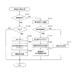
次いで、主制御装置261内のCPU501により実行される各制御処理を、フローチャートを参照しながら説明する。かかるCPU501の処理としては大別して、電源投入に伴い起動されるメイン処理と、定期的に(本実施形態では2msec周期で)起動されるタイマ割込み処理と、NMI端子(ノンマスカブル端子)への停止信号の入力により起動されるNMI割込み処理とがあり、説明の便宜上ここでは、先ずタイマ割込み処理とNMI割込み処理とを説明し、その後でメイン処理を説明する。
Next, each control process executed by the
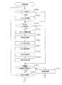
図14は、タイマ割込み処理を示すフローチャートであり、本処理は主制御装置261のCPU501により例えば2msec毎に実行される。
FIG. 14 is a flowchart showing the timer interrupt process. This process is executed by the
図14において、先ずステップS301では、各種入賞スイッチの読み込み処理を実行する。すなわち、主制御装置261に接続されている各種スイッチ(但し、RAM消去スイッチ323を除く)の状態を読み込むと共に、当該スイッチの状態を判定して検出情報(入賞検知情報)を保存する。
In FIG. 14, first, in step S301, reading processing of various winning switches is executed. That is, the state of various switches (except for the RAM erase switch 323) connected to the
ステップS302では乱数初期値更新処理を実行する。具体的には、乱数初期値カウンタCINIを1インクリメントすると共に、そのカウンタ値が最大値(本例では917)に達した際0にクリアする。 In step S302, random number initial value update processing is executed. Specifically, the random number initial value counter CINI is incremented by 1 and cleared to 0 when the counter value reaches the maximum value (917 in this example).
また、ステップS303では乱数更新処理を実行する。具体的には、大当たり乱数カウンタC1、モード決定カウンタC2、変動選択カウンタC3及び普通図柄乱数カウンタC4をそれぞれ1インクリメントすると共に、それらのカウンタ値が最大値(本実施の形態ではそれぞれ、917,9,238,250)に達した際それぞれ0にクリアする。そして、各カウンタC1,C2,C3,C4の更新値を、RAM503の該当するバッファ領域に格納する。
In step S303, random number update processing is executed. Specifically, the jackpot random number counter C1, the mode determination counter C2, the variation selection counter C3, and the normal symbol random number counter C4 are each incremented by 1 and their counter values are maximum values (in this embodiment, 917, 9 respectively). , 238, 250) is cleared to 0 respectively. Then, the updated values of the counters C1, C2, C3, and C4 are stored in the corresponding buffer area of the
その後、ステップS304では、第1契機対応ユニット33への入賞に伴う始動入賞処理を実行し、ステップS305では、第2契機対応口34への遊技球の通過に伴う第2契機対応口通過処理を実行する。その後、タイマ割込み処理を一旦終了する。
Thereafter, in step S304, a start winning process associated with winning the first
ここで、ステップS304の始動入賞処理について図16のフローチャートを参照して説明する。ステップS501では、遊技球が第1契機対応ユニット33に入賞したか否かを第1契機対応ユニットスイッチ224の検出情報により判別する。遊技球が第1契機対応ユニット33に入賞したと判別されると、続くステップS502では、始動保留球数Naが上限値(本実施形態では4)未満であるか否かを判別する。第1契機対応ユニット33への入賞があり、且つ始動保留球数Na<4であることを条件にステップS503に進み、始動保留球数Naをインクリメントする。
Here, the start winning process in step S304 will be described with reference to the flowchart of FIG. In step S501, whether or not the game ball has won the first
また、続くステップS504では、当否に関わる乱数を取得する。具体的には、上記ステップS303の乱数更新処理で更新した大当たり乱数カウンタC1、モード決定カウンタC2及び変動選択カウンタC3の各値を、RAM503の第1保留球格納エリアの空き記憶エリアのうち最初のエリアに格納する。その後、始動入賞処理を一旦終了する。従って、この始動入賞処理の機能により本実施形態における抽選手段(当否抽選処理)の一部が構成される。
In subsequent step S504, a random number related to the success or failure is acquired. Specifically, the values of the jackpot random number counter C1, the mode determination counter C2, and the variation selection counter C3 updated by the random number update process in step S303 are used as the first free storage area in the first reserved ball storage area of the
次に、ステップS305の第2契機対応口通過処理について図17のフローチャートを参照して説明する。 Next, the second opportunity corresponding port passing process in step S305 will be described with reference to the flowchart of FIG.
ステップS601では、遊技球が第2契機対応口34を通過したか否かを第2契機対応スイッチ225の検出情報により判別する。
In step S601, whether or not the game ball has passed through the second opportunity corresponding port 34 is determined based on the detection information of the second
ステップS601で否定判別された場合、そのまま本処理を終了する。一方、ステップS601にて肯定判別された場合、すなわち、遊技球が第2契機対応口34を通過したと判別されると、ステップS602において、普通図柄表示装置41の保留球数Nbが上限値(本実施形態では4)未満であるか否かを判別する。ここで否定判別された場合には、そのまま本処理を終了する。一方、ステップS602で肯定判別された場合、すなわち、第2契機対応口34への遊技球の通過が確認され、且つ、保留球数Nb<4であることを条件にステップS603に進み、保留球数Nbを1インクリメントする。
If a negative determination is made in step S601, the present process is terminated as it is. On the other hand, if an affirmative determination is made in step S601, that is, if it is determined that the game ball has passed through the second opportunity corresponding port 34, the number Nb of reserved balls in the normal
また、続くステップS604では、当否に関わる乱数を取得する。具体的には、上記ステップS303の乱数更新処理で更新した普通図柄乱数カウンタC4の値を、RAM503の第2保留球格納エリアの空き記憶エリアのうち最初のエリアに格納する。その後、第2契機対応口通過処理を終了する。
In subsequent step S604, a random number related to the success or failure is acquired. Specifically, the value of the normal symbol random number counter C4 updated by the random number update process in step S303 is stored in the first area of the free storage area of the second reserved ball storage area of the
図15は、NMI割込み処理を示すフローチャートであり、本処理は、主制御装置261のCPU501により停電の発生等によるパチンコ機10の電源断時に実行される。このNMI割込みにより、電源断時の主制御装置261の状態がRAM503のバックアップエリア503aに記憶される。
FIG. 15 is a flowchart showing the NMI interrupt process, and this process is executed by the
すなわち、停電の発生等によりパチンコ機10の電源が遮断されると、停電信号SK1が停電監視回路542から主制御装置261内のCPU501のNMI端子に出力される。すると、CPU501は実行中の制御を中断してNMI割込み処理を開始し、ステップS401において、電源断の発生情報の設定として電源断の発生情報をRAM503のバックアップエリア503aに記憶してNMI割込み処理を終了する。
That is, when the power of the
なお、上記のNMI割込み処理は払出制御装置311でも同様に実行され、かかるNMI割込みにより、電源断の発生情報がRAM513のバックアップエリア513aに記憶される。すなわち、停電の発生等によりパチンコ機10の電源が遮断されると、停電信号SK1が停電監視回路542から払出制御装置311内のCPU511のNMI端子に出力され、CPU511は実行中の制御を中断して図15のNMI割込み処理を開始する。その内容は上記説明の通りである。
The above NMI interrupt processing is executed in the same manner in the
次に、主制御装置261内のCPU501により実行されるメイン処理の流れを図12のフローチャートを参照しながら説明する。このメイン処理は電源投入時のリセットに伴い起動される。
Next, the flow of main processing executed by the
先ず、ステップS101では、電源投入に伴う初期設定処理を実行する。具体的には、スタックポインタに予め決められた所定値を設定すると共に、サブ側の制御装置(サブ制御装置262,払出制御装置311等)が動作可能な状態になるのを待つために例えば1秒程度、ウェイト処理を実行する。続くステップS102では、RAMアクセスを許可する。
First, in step S101, an initial setting process associated with power-on is executed. Specifically, for example, 1 is set in order to set a predetermined value in the stack pointer and wait for the sub-side control device (
その後、CPU501内のRAM503に関してデータバックアップの処理を実行する。つまり、ステップS103では、電源装置313に設けたRAM消去スイッチ323が押下(ON)されているか否かを判別し、押下されていれば、バックアップデータをクリア(消去)するべく、ステップS112へ移行する。一方、RAM消去スイッチ323が押下されていなければ、続くステップS104で、RAM503のバックアップエリア503aに電源断の発生情報が設定されているか否かを判別する。ここで、設定されていなければ、バックアップデータは記憶されていないので、この場合もステップS112へ移行する。バックアップエリア503aに電源断の発生情報が設定されていれば、ステップS105でRAM判定値を算出し、続くステップS106では、そのRAM判定値が電源断時に保存したRAM判定値と一致するか否か、すなわちバックアップの有効性を判別する。ここで算出したRAM判定値が電源断時に保存したRAM判定値と一致しなければ、バックアップされたデータは破壊されているので、この場合もステップS112へ移行する。
Thereafter, data backup processing is executed for the
ステップS112の処理では、サブ側の制御装置となるサブ制御装置262及び払出制御装置311等を初期化するために、初期化コマンドを送信する。その後、RAMの初期化処理(ステップS113等)に移行する。なお、RAM判定値は、例えばRAM503の作業領域アドレスにおけるチェックサム値である。このRAM判定値に代えて、RAM503の所定のエリアに書き込まれたキーワードが正しく保存されているか否かによりバックアップの有効性を判断することも可能である。
In the process of step S112, an initialization command is transmitted in order to initialize the
上述したように、本パチンコ機10では、例えばホールの営業開始時など、電源投入時に初期状態に戻したい場合にはRAM消去スイッチ323を押しながら電源が投入される。従って、RAM消去スイッチ323がONされていれば、RAMの初期化処理(ステップS113等)に移行する。また、電源断の発生情報が設定されていない場合や、RAM判定値(チェックサム値等)によりバックアップの異常が確認された場合も同様にRAM503の初期化処理(ステップS113等)に移行する。つまり、ステップS113ではRAM503の使用領域を0にクリアし、続くステップS114ではRAM503の初期値を設定する。その後、ステップS111で割込み許可を設定し、後述する通常処理に移行する。
As described above, the
一方、RAM消去スイッチ323が押されていない場合(ステップS103:NO)には、電源断の発生情報が設定されていること、及びRAM判定値(チェックサム値等)が正常であることを条件に、復電時の処理(電源断復旧時の処理)を実行する。つまり、ステップS107では、電源断前のスタックポインタを復帰させ、ステップS108では、電源断の発生情報をクリアする。ステップS109では、サブ側の制御装置を電源断時の遊技状態に復帰させるコマンドを送信し、ステップS110では、使用レジスタをRAM503のバックアップエリア503aから復帰させる。その後、ステップS111で割込み許可を設定し、後述する通常処理に移行する。
On the other hand, if the RAM erase
次に、通常処理の流れを図13のフローチャートを参照しながら説明する。この通常処理では遊技の主要な処理が実行される。その概要として、ステップS201〜S210の処理が4msec周期の定期処理として実行され、その残余時間でステップS211,ステップS212のカウンタ更新処理が実行される構成となっている。 Next, the flow of normal processing will be described with reference to the flowchart of FIG. In this normal process, the main process of the game is executed. As its outline, the processing of steps S201 to S210 is executed as a periodic processing with a period of 4 msec, and the counter update processing of steps S211 and S212 is executed with the remaining time.
先ずステップS201では、前回の処理で更新された特別表示装置43や第1契機対応ユニット33等の設定内容に基づいた制御信号を各装置に送信したり、コマンド等の出力データをサブ側の各制御装置に送信したりする外部出力処理を実行する。
First, in step S201, a control signal based on the setting contents of the
例えば、装飾図柄表示装置42による装飾図柄の変動表示に際して、変動パターンコマンド、図柄コマンド等をサブ制御装置262に送信する。つまり、変動パターンコマンドや図柄コマンドは、特別表示装置43にて行われる表示に合わせた表示演出を装飾図柄表示装置42にて行わせるためにサブ制御装置262に出力されるコマンドであり、本実施形態における指令情報に相当する。従って、この外部出力処理の機能が本実施形態における指令情報出力手段を構成する。これに対し、変動パターンコマンド、図柄コマンド等を入力したサブ制御装置262は、かかる各種コマンドに基づいて、装飾図柄表示装置42の変動態様を決定し、該変動態様を装飾図柄表示装置42において表示(変動表示)するように表示制御装置45に対し指示を出す。
For example, when the decorative
便宜上、ここで変動パターンコマンド等について説明する。変動パターンコマンドには、ノーマルリーチ、スーパーリーチ、プレミアムリーチといった装飾図柄の変動種別を特定する情報が含まれている。本実施形態では、例えば通常モード時には「FF10」,「FF11」,「FF12」,「FF13」,「FF14」,「FF15」,「FF16」のうちのいずれかが変動パターンコマンドとして設定される。また、高確率モード時には、「FD10」,「FD11」,「FD12」,「FD13」,「FD14」,「FD15」,「FD16」が設定され、時間短縮モード時には、「FE10」,「FE11」,「FE12」,「FE13」,「FE14」,「FE15」,「FE16」が設定される。一方、サブ制御装置262には、これらの変動パターンコマンドと装飾図柄の変動種別との関係がテーブルで記憶されている。そして、サブ制御装置262は、変動パターンコマンドに対応する演出パターンを実行する。
For convenience, the variation pattern command and the like will be described here. The variation pattern command includes information for specifying the variation type of the decorative symbol such as normal reach, super reach, and premium reach. In the present embodiment, for example, in the normal mode, any one of “FF10”, “FF11”, “FF12”, “FF13”, “FF14”, “FF15”, and “FF16” is set as the variation pattern command. In the high probability mode, “FD10”, “FD11”, “FD12”, “FD13”, “FD14”, “FD15”, “FD16” are set, and in the time reduction mode, “FE10”, “FE11”. , “FE12”, “FE13”, “FE14”, “FE15”, “FE16” are set. On the other hand, the
以下、装飾図柄の変動種別、及び、変動種別と変動パターンコマンドとの対応関係について説明する。 Hereinafter, the variation type of the decorative symbol and the correspondence between the variation type and the variation pattern command will be described.
ノーマルリーチは、装飾図柄の変動以外には特段の演出表示がされないリーチパターンである。そして、ノーマルリーチに対応する変動パターンコマンドには通常モード時には「FF11」が設定され、高確率モード時には「FD11」が設定され、時間短縮モード時には「FE11」が設定される。なお、本実施形態では、ノーマルリーチが導出される変動表示時間は通常モード時「20秒」、高確率モード時「8秒」、時間短縮モード時「10秒」に設定されている。 Normal reach is a reach pattern that does not display any special effects other than the variation of the decorative design. In the variation pattern command corresponding to the normal reach, “FF11” is set in the normal mode, “FD11” is set in the high probability mode, and “FE11” is set in the time reduction mode. In this embodiment, the variable display time for which the normal reach is derived is set to “20 seconds” in the normal mode, “8 seconds” in the high probability mode, and “10 seconds” in the time reduction mode.
スーパーリーチは、装飾図柄の変動表示中(リーチ状態成立後)において、装飾図柄以外にも、装飾図柄表示装置42にキャラクタ等が表示され、これにより遊技者に対し期待感を抱かせるリーチパターンである。本実施形態では、スーパーリーチには通常モード時で30秒、40秒、50秒パターンの3種類(スーパーリーチSR1,SR2,SR3)が用意されている。なお、高確率モード時及び時間短縮モード時の変動表示時間は、上記ノーマルリーチ同様に通常モード時に比べ時間短縮されている。各リーチパターンに対応して、スーパーリーチSR1ならば通常モード時「FF12」、高確率モード時「FD12」、時間短縮モード時「FE12」が変動パターンコマンドに設定される。スーパーリーチSR2ならば通常モード時「FF13」、高確率モード時「FD13」、時間短縮モード時「FE13」が設定される。スーパーリーチSR3ならば通常モード時「FF14」、高確率モード時「FD14」、時間短縮モード時「FE14」が設定される。
Super Reach is a reach pattern in which characters and the like are displayed on the decorative
プレミアムリーチは、大当たり状態が発生する際にのみ導出され得る演出態様であり、装飾図柄の変動表示中(リーチ状態成立後)において、装飾図柄以外に、スーパーリーチとは異なるパターンのキャラクタ等が表示される態様で行われ、これにより遊技者に対し期待感を抱かせるリーチパターンである。本実施形態のプレミアムリーチには通常モード時で60秒、70秒パターンの2種類(プレミアムリーチPR1,PR2)が用意されている。なお、高確率モード時及び時間短縮モード時の変動表示時間は、上記ノーマルリーチ同様に通常モード時に比べ時間短縮されている。各リーチパターンに対応して、プレミアムリーチPR1ならば通常モード時「FF15」、高確率モード時「FD15」、時間短縮モード時「FE15」が変動パターンコマンドに設定される。プレミアムリーチPR2ならば通常モード時「FF16」、高確率モード時「FD16」、時間短縮モード時「FE16」が設定される。 Premium reach is an effect that can be derived only when a big hit state occurs. During the decorative symbol variation display (after reaching the reach state), in addition to the decorative symbol, a character with a different pattern from the super reach is displayed. This is a reach pattern that makes the player have a sense of expectation. In the premium reach of this embodiment, two types (premium reach PR1, PR2) of 60-second and 70-second patterns are prepared in the normal mode. Note that the variable display time in the high probability mode and in the time reduction mode is shortened compared to that in the normal mode, as in the normal reach. Corresponding to each reach pattern, in the premium reach PR1, “FF15” in the normal mode, “FD15” in the high probability mode, and “FE15” in the time reduction mode are set as the variation pattern command. In the premium reach PR2, “FF16” in the normal mode, “FD16” in the high probability mode, and “FE16” in the time reduction mode are set.
また、いずれのリーチ状態にもならない「完全外れ」に対応する変動パターンコマンドには通常モード時「FF10」、高確率モード時「FD10」、時間短縮モード時「FE10」が変動パターンコマンドに設定される。本実施形態では、完全外れとなる変動表示時間は通常モード時で10秒に設定されている。もちろん、高確率モード時及び時間短縮モード時の変動表示時間は、上記ノーマルリーチ同様に通常モード時に比べ時間短縮されている。 In addition, the fluctuation pattern command corresponding to “complete out” that does not reach any reach state is set to “FF10” in the normal mode, “FD10” in the high probability mode, and “FE10” in the time reduction mode. The In the present embodiment, the variable display time that is completely off is set to 10 seconds in the normal mode. Of course, the variable display time in the high probability mode and the time shortening mode is shortened compared to the normal mode as in the normal reach.
また、サブ制御装置262は、図柄コマンドに基づき停止図柄(停止図柄の組合わせ)を決定して、変動時間経過後に表示する。図柄コマンドは、サブ制御装置262に停止図柄を決定させるコマンドであり、確変図柄の組合わせ、通常図柄の組合わせ、前後外れ図柄の組合わせ、前後外れ以外図柄の組合わせ、完全外れ図柄の組合わせという5つの区分を指定するものである。これらの区分は、例えば、「A1」,「A2」,「A3」,「A4」,「A5」で示され、この内のいずれかが図柄コマンドとして設定される。一方、サブ制御装置262には、これらのコマンドと停止図柄との関係がテーブルで記憶されている。そして、サブ制御装置262は、図柄コマンドに対応する停止図柄を表示する。
Further, the
以下、停止図柄の区分及び、停止図柄と図柄コマンドとの対応関係について説明する。 Hereinafter, the stop symbol classification and the correspondence between the stop symbol and the symbol command will be described.
確変図柄の組合わせは、1,3,5,7,9の数字のゾロ目からなる図柄の組合わせであり、確変図柄の組合わせに対応する図柄コマンドには「A1」が設定される。そして、サブ制御装置262は、図柄コマンドに確変図柄を示す「A1」が設定されている場合、1,3,5,7,9の数字のゾロ目からなる図柄の組合わせのうちの一つを停止図柄として決定する。
The combination of probability variation symbols is a combination of symbols composed of
通常図柄の組合わせは、0,2,4,6,8の数字のゾロ目からなる図柄の組合わせであり、通常図柄の組合わせに対応する図柄コマンドには「A2」が設定される。そして、サブ制御装置262は、図柄コマンドに通常図柄を示す「A2」が設定されている場合、0,2,4,6,8の数字のゾロ目からなる図柄の組合わせのうちの一つを停止図柄として決定する。
The combination of normal symbols is a combination of symbols consisting of
前後外れ図柄の組合わせは、リーチ発生した後、最終停止図柄がリーチ図柄の前後に1つだけずれて停止する「前後外れリーチ」に対応するものであり、前後外れ図柄の組合わせに対応する図柄コマンドには「A3」が設定される。前後外れ以外図柄の組合わせは、リーチ発生した後、最終停止図柄がリーチ図柄の前後以外で停止する「前後外れ以外リーチ」に対応するものであり、前後外れ以外図柄の組合わせに対応する図柄コマンドには「A4」が設定される。完全外れ図柄の組合わせは、リーチ発生しない「完全外れ」に対応するものであり、完全外れ図柄の組合わせに対応する図柄コマンドには「A5」が設定される。なお、詳しくは後述するが、図柄コマンドに「A3」〜「A5」が設定されている場合、サブ制御装置262は、対応するRAM553のカウンタ用バッファに格納されている図柄の組合わせを停止図柄として決定する。本実施形態では、外れ用の図柄コマンドに「A3」〜「A5」の3つのコマンドを用意しているが、これに限らず、例えば外れ用の図柄コマンドが1つだけの構成としてもよい。
The combination of back and forth symbols corresponds to the combination of back and forth symbols, where after reaching, the final stop symbol is stopped by one shift before and after the reach symbol. “A3” is set in the symbol command. The combination of symbols other than front / rear detachment corresponds to the “reach other than front / rear detachment” that occurs after reach occurs, and the final stop symbol stops other than before / after the reach symbol. “A4” is set in the command. The combination of complete detachment symbols corresponds to “complete detachment” in which no reach occurs, and “A5” is set in the symbol command corresponding to the combination of complete detachment symbols. As will be described in detail later, when “A3” to “A5” are set in the symbol command, the
図13の説明に戻り、ステップS202では、変動種別カウンタCS1,CS2の更新を実行する。より具体的には、他のカウンタと同様に、変動種別カウンタCS1,CS2を1インクリメントすると共に、それらのカウンタ値が上限値(本実施形態では198,240)に達した際、それぞれ0にクリアする。そして、変動種別カウンタCS1,CS2の更新値を、RAM503の該当するバッファ領域に格納する。
Returning to the description of FIG. 13, in step S202, the variation type counters CS1 and CS2 are updated. More specifically, like the other counters, the variation type counters CS1 and CS2 are incremented by 1 and cleared to 0 when the counter values reach the upper limit values (198 and 240 in this embodiment). To do. Then, the update values of the variation type counters CS1 and CS2 are stored in the corresponding buffer area of the
続くステップS203では、払出制御装置311より受信した賞球計数信号を読み込む。次に、ステップS204では、払出制御装置311より受信した払出異常信号を読み込む。
In the subsequent step S203, the prize ball counting signal received from the
その後、ステップS205では、第1表示制御処理を実行する。この処理では、特別表示装置43においてどのような制御を行うか当該特別表示装置43の制御内容の設定が行われると共に、大当たり判定や装飾図柄表示装置42における装飾図柄の変動パターン(演出パターン)の設定などが行われる。この第1表示制御処理の詳細は後述する。
Thereafter, in step S205, a first display control process is executed. In this process, the control content of the
ステップS206では、可変入賞装置制御処理を実行する。この処理では、可変入賞装置32においてどのような制御を行うか当該可変入賞装置32の制御内容の設定が行われる。これにより、大当たり状態(特別遊技状態)となった場合には、可変入賞装置32の大入賞口の開閉処理が所定ラウンド数繰り返し実行される。可変入賞装置制御処理の詳細は後述する。
In step S206, variable winning device control processing is executed. In this process, the control content of the variable winning
ステップS207では、第2表示制御処理を実行する。この処理では、普通図柄表示装置41おいてどのような制御を行うか当該普通図柄表示装置41の制御内容の設定などが行われる。この第2表示制御処理の詳細は後述する。
In step S207, the second display control process is executed. In this process, the control contents of the normal
ステップS208では、契機対応ユニット制御処理を実行する。この処理では、第1契機対応ユニット33においてどのような制御を行うか当該第1契機対応ユニット33の制御内容の設定が行われる。
In step S208, an opportunity handling unit control process is executed. In this process, the control content of the first
その後は、ステップS209において、RAM503のバックアップエリア503aに電源断の発生情報が設定されているか否かを判別する。ここでバックアップエリア503aに電源断の発生情報が設定されていなければ、ステップS210で、次の通常処理の実行タイミングに至ったか否か、すなわち前回の通常処理の開始から所定時間(本実施の形態では4msec)が経過したか否かを判別する。そして、既に所定時間が経過していれば、ステップS201へ移行し、上記ステップS201以降の処理を繰り返し実行する。
After that, in step S209, it is determined whether or not occurrence information of power interruption is set in the backup area 503a of the
一方、前回の通常処理の開始から未だに所定時間が経過していなければ、次の通常処理の実行タイミングに至るまでの残余時間内において、乱数初期値カウンタCINI及び変動種別カウンタCS1,CS2の更新を繰り返し実行する(ステップS211,ステップS212)。 On the other hand, if the predetermined time has not yet elapsed from the start of the previous normal process, the random number initial value counter CINI and the variation type counters CS1 and CS2 are updated within the remaining time until the execution timing of the next normal process. Repeatedly execute (step S211, step S212).
つまり、ステップS211では、乱数初期値カウンタCINIの更新を実行する。具体的には、乱数初期値カウンタCINIを1インクリメントすると共に、そのカウンタ値が最大値(本例では917)に達した際0にクリアする。 That is, in step S211, the random number initial value counter CINI is updated. Specifically, the random number initial value counter CINI is incremented by 1 and cleared to 0 when the counter value reaches the maximum value (917 in this example).
また、ステップS212では、変動種別カウンタCS1,CS2の更新を実行する(前記ステップS202と同様)。具体的には、変動種別カウンタCS1,CS2を1インクリメントすると共に、それらのカウンタ値が最大値(本例では198,240)に達した際それぞれ0にクリアする。そして、変動種別カウンタCS1,CS2の変更値を、RAM503の該当するバッファ領域に格納する。
In step S212, the variation type counters CS1 and CS2 are updated (similar to step S202). Specifically, the variation type counters CS1 and CS2 are incremented by 1, and are cleared to 0 when the counter values reach the maximum values (198 and 240 in this example). Then, the change values of the variation type counters CS1 and CS2 are stored in the corresponding buffer area of the
ここで、ステップS201〜S209の各処理の実行時間は遊技の状態に応じて変化するため、次の通常処理の実行タイミングに至るまでの残余時間は一定ではなく変動する。故に、かかる残余時間を使用して乱数初期値カウンタCINIの更新を繰り返し実行することにより、乱数初期値カウンタCINI(すなわち大当たり乱数カウンタC1の初期値)をランダムに更新することができ、同様に変動種別カウンタCS1,CS2についてもランダムに更新することができる。 Here, since the execution time of each process of steps S201 to S209 changes according to the state of the game, the remaining time until the next execution timing of the normal process is not constant and varies. Therefore, it is possible to update the random number initial value counter CINI (that is, the initial value of the big hit random number counter C1) at random by repeatedly executing the update of the random number initial value counter CINI using the remaining time, and similarly change The type counters CS1 and CS2 can also be updated at random.
さて、RAM503のバックアップエリア503aに電源断の発生情報が設定されていれば(ステップS209:YES)、電源が遮断されたことになるので、電源断時の停電処理としてステップS213以降の処理が行われる。停電処理は、まずステップS213において各割込み処理の発生を禁止し、ステップS214において、CPU501が使用している各レジスタの内容をスタックエリアに退避し、ステップS215において、スタックポインタの値をバックアップエリア503aに記憶する。その後、ステップS216において、電源が遮断されたことを示す電源断通知コマンドを他の制御装置(払出制御装置311等)に対して送信する。そして、ステップS217でRAM判定値を算出し、バックアップエリア503aに保存する。RAM判定値は、例えば、RAM503の作業領域アドレスにおけるチェックサム値である。その後、ステップS218でRAMアクセスを禁止して、電源が完全に遮断して処理が実行できなくなるまで無限ループを継続する。
Now, if the occurrence information of power interruption is set in the backup area 503a of the RAM 503 (step S209: YES), the power is cut off, so that the processing after step S213 is performed as a power failure process at the time of power interruption. Is called. In the power failure process, first, the generation of each interrupt process is prohibited in step S213, the contents of each register used by the
なお、ステップS209の処理は、ステップS201〜S208で行われる遊技の状態変化に対応した一連の処理の終了時、又は、残余時間内に行われるステップS211,S212の処理の1サイクルの終了時となるタイミングで実行されている。よって、主制御装置261の通常処理において、各処理の終了時に電源断の発生情報を確認しているので、各処理が途中の場合と比較してRAM503のバックアップエリア503aに記憶するデータ量が少なくなり、容易に記憶することができる。また、電源遮断前の状態に復帰する場合には、バックアップエリア503aに記憶されているデータ量が少ないので、容易に復帰させることができ、主制御装置261の処理の負担を軽減することができる。さらに、データの記憶前に割込み処理の発生を禁止(ステップS213)するので、電源が遮断されたときのデータが変更されることを防止でき、電源遮断前の状態を確実に記憶することができる。
The process of step S209 is performed at the end of a series of processes corresponding to the game state change performed at steps S201 to S208, or at the end of one cycle of the processes of steps S211 and S212 performed within the remaining time. It is executed at the timing. Therefore, in the normal process of the
次に、前記ステップS205の第1表示制御処理について図18のフローチャートを参照して説明する。 Next, the first display control process of step S205 will be described with reference to the flowchart of FIG.
図18において、ステップS801では、詳しくは後述する大当たりフラグを参照し、今現在、大当たり中であるか否かを判別する。なお、大当たり中には、大当たり状態(特別遊技状態)の最中と大当たり状態終了後の所定時間(ここで言う大当たり状態終了後の所定時間とは、大当たり状態終了後、通常遊技(特別表示装置43における変動表示)が開始されるまでの時間であり、一般にこの時間帯は、装飾図柄表示装置42にて大当たり状態の終了や大当たり後に付与されるモードを示す表示が行われる)とが含まれる。また、特別表示装置43及び装飾図柄表示装置42にて変動表示が大当たりに対応する態様にて停止表示されてから可変入賞装置32(大入賞口)が開放されるまでの間の期間(一般にこの時間帯は装飾図柄表示装置42にて大当たり状態の開始を示す表示が行われる)についても大当たり中に含まれる。
In FIG. 18, in step S801, a jackpot flag, which will be described later, is referred to in detail to determine whether or not the jackpot is currently being hit. During the jackpot, during the jackpot state (special game state) and for a predetermined time after the jackpot state ends (the predetermined time after the jackpot state ends here is a normal game (special display device) after the jackpot state ends (Variable display at 43) is started, and in general, this time zone includes the display of the end of the jackpot state and the mode given after the jackpot on the decorative symbol display device 42) . In addition, a period from when the variable display is stopped and displayed on the
続くステップS802では、第1表示中フラグの設定状況を見て特別表示装置43による色換え表示(変動表示)中であるか否かを判別する。詳しくは、第1表示中フラグが設定されている場合(オン状態の場合)には変動表示中とみなされ、第1表示中フラグが解除されている場合(オフ状態の場合)には、変動表示が停止した状態にあたる停止表示中であるとみなされる。そして、大当たり中でなくさらに変動表示中でもない場合、ステップS803に進み、始動保留球数Naが0よりも大きいか否かを判別する。このとき、大当たり中であるか、又は始動保留球数Naが0である場合、そのまま本処理を終了する。尚、詳しくは後述するが、第1表示中フラグは、特別表示装置43の変動表示を開始する際(ステップS917参照)にオンにされ、特別表示装置43の変動表示が停止表示される際(ステップS809参照)にオフにされる。
In the subsequent step S802, it is determined whether or not the
また、大当たり中、変動表示中の何れでもなく且つ始動保留球数Na>0であれば、ステップS804に進む。ステップS804では、始動保留球数Naから1を減算する。ステップS805では、第1保留球格納エリアに格納されたデータをシフトさせる処理を実行する。このデータシフト処理は、第1保留球格納エリアの保留第1〜第4エリアに格納されているデータを実行エリア側に順にシフトさせる処理であって、保留第1エリア→実行エリア、保留第2エリア→保留第1エリア、保留第3エリア→保留第2エリア、保留第4エリア→保留第3エリアといった具合に各エリア内のデータがシフトされる。 If neither the big hit or the variable display is being displayed and if the number of starting reserved balls Na> 0, the process proceeds to step S804. In step S804, 1 is subtracted from the starting reserved ball number Na. In step S805, processing for shifting the data stored in the first reserved ball storage area is executed. This data shift process is a process for sequentially shifting the data stored in the first to fourth areas on hold in the first holding ball storage area to the execution area side. Data in each area is shifted, such as area → holding first area, holding third area → holding second area, holding fourth area → holding third area.
その後、ステップS806では、変動表示設定処理を実行する。ここで、図19のフローチャートを用いて変動表示設定処理の詳細を説明する。 Thereafter, in step S806, a variable display setting process is executed. Here, details of the variable display setting process will be described with reference to the flowchart of FIG.
まず、ステップS901では、第1保留球格納エリアの実行エリアに格納されている大当たり乱数カウンタC1の値に基づいて大当たりか否かを判別する。具体的には、大当たりか否かは大当たり乱数カウンタC1の値とその時々のモードとの関係に基づいて判別され、前述した通り通常モード等の低確率状態では大当たり乱数カウンタC1の数値0〜917のうち「147、341、533」が当たり値であり、高確率モードでは「141〜150、341〜350、531〜540」が当たり値である。ここで大当たりであると判断された場合(ステップS901:YES)、ステップS902へ移行する。一方、大当たりでないと判断された場合(ステップS901:NO)、すなわち外れである場合には、ステップS909へ移行する。
First, in step S901, it is determined whether or not a big hit is made based on the value of the big hit random number counter C1 stored in the execution area of the first reserved ball storage area. Specifically, whether or not the jackpot is hit is determined based on the relationship between the value of the jackpot random number counter C1 and the mode at that time. As described above, in the low probability state such as the normal mode, the
ステップS902では、確変大当たりであるか否かを判断する。本実施形態では、大当たりとなった場合、それぞれ1/2の確率で高確率モード又は時間短縮モードへ移行するように構成されている。具体的には、高確率モードへ移行させるか否かは、第1保留球格納エリアの実行エリアに格納されているモード決定カウンタC2の値に基づいて判断される。格納されているモード決定カウンタC2の値が、数値0〜9のうち奇数「1,3,5,7,9」であるならば高確率モードへの移行が決定され(確変大当たり)、偶数「0,2,4,6,8」であるならば時間短縮モードへの移行が決定される(通常大当たり)。
In step S902, it is determined whether or not the probability variation jackpot. In the present embodiment, the system is configured to shift to the high probability mode or the time reduction mode with a probability of 1/2 in the case of a big hit. Specifically, whether or not to shift to the high probability mode is determined based on the value of the mode determination counter C2 stored in the execution area of the first reserved ball storage area. If the value of the stored mode determination counter C2 is an odd number “1, 3, 5, 7, 9” among the
ここで確変大当たりであると判断された場合(ステップS902:YES)、ステップS904にて大当たり変動パターンを決定し、ステップS905にて確変図柄(本実施形態では「A1」)を図柄コマンドに設定して、ステップS917へ移行する。 Here, when it is determined that the probability variation jackpot (step S902: YES), the jackpot variation pattern is determined in step S904, and the probability variation symbol (“A1” in the present embodiment) is set to the symbol command in step S905. Then, the process proceeds to step S917.
一方、ステップS902で確変大当たりでないと判断された場合(ステップS902:NO)、すなわち通常大当たりである場合には、ステップS907にて大当たり変動パターンを決定し、ステップS908にて通常図柄(本実施形態では「A2」)を図柄コマンドに設定して、ステップS917へ移行する。 On the other hand, if it is determined in step S902 that it is not a probable big hit (step S902: NO), that is, if it is a normal big hit, a big hit variation pattern is determined in step S907, and a normal symbol (this embodiment) is determined in step S908. Then, “A2”) is set as the symbol command, and the process proceeds to step S917.
上記ステップS904,ステップS907では、大当たり時における変動パターンを決定し、当該変動パターンを変動パターンコマンドに設定する。このとき、RAM503のカウンタ用バッファに格納されている変動種別カウンタCS1,CS2の値を確認し、第1及び第2変動種別カウンタCS1、CS2の値に基づいて装飾図柄の図柄変動態様を決定する。なお、第1変動種別カウンタCS1の数値とリーチパターン(変動種別)との関係、第2変動種別カウンタCS2の数値と変動時間との関係は、各遊技モード毎にテーブル等により予め規定されている。なお、本実施形態におけるモード判別は、後述する高確率状態フラグ、時間短縮状態フラグ及び高入球状態フラグのオンオフ状況の組合せにより行われる。例えば、高確率状態フラグ、時間短縮状態フラグ及び高入球状態フラグが全てオン状態(フラグ値「1」)であれば、高確率モードと判別される。
In steps S904 and S907, the variation pattern at the time of the big hit is determined, and the variation pattern is set in the variation pattern command. At this time, the values of the variation type counters CS1 and CS2 stored in the counter buffer of the
ここで、第1変動種別カウンタCS1及び第2変動種別カウンタCS2の数値と変動種別との対応関係について説明する。例えば通常モード中の大当たり時においては、図21(a)に示すような通常モード中大当たり時テーブルによって前記対応関係が規定されている。すなわち、CS1=0〜9のときは、CS2の値に関わらず、変動パターンコマンドに「FF11」(ノーマルリーチ)が設定される。CS1=10〜196かつCS2=0〜69のときは、変動パターンコマンドに「FF12」(スーパーリーチSR1)が設定される。CS1=10〜196かつCS2=70〜149のときは、変動パターンコマンドに「FF13」(スーパーリーチSR2)が設定される。CS1=10〜196かつCS2=150〜240のときは、変動パターンコマンドに「FF14」(スーパーリーチSR3)が設定される。CS1=197,198かつCS2=0〜120のときは、変動パターンコマンドに「FF15」(プレミアムリーチPR1)が設定される。CS1=197,198かつCS2=121〜240のときは、変動パターンコマンドに「FF16」(プレミアムリーチPR2)が設定される。 Here, the correspondence between the numerical values of the first variation type counter CS1 and the second variation type counter CS2 and the variation type will be described. For example, at the big hit time in the normal mode, the correspondence is defined by a normal mode big hit table as shown in FIG. That is, when CS1 = 0 to 9, “FF11” (normal reach) is set in the variation pattern command regardless of the value of CS2. When CS1 = 10 to 196 and CS2 = 0 to 69, “FF12” (super reach SR1) is set in the variation pattern command. When CS1 = 10 to 196 and CS2 = 70 to 149, “FF13” (super reach SR2) is set in the variation pattern command. When CS1 = 10 to 196 and CS2 = 150 to 240, “FF14” (super reach SR3) is set in the variation pattern command. When CS1 = 197, 198 and CS2 = 0-120, “FF15” (premium reach PR1) is set in the variation pattern command. When CS1 = 197, 198 and CS2 = 121-240, “FF16” (premium reach PR2) is set in the variation pattern command.
また、ステップS905,ステップS908における図柄コマンドは、大当たりの図柄を所定区分で指示するものであり、停止図柄の決定は、後述するようにサブ制御装置262が行う。具体的には、確変図柄の組合わせを示す「A1」が図柄コマンドに設定されると(ステップS905)、1,3,5,7,9のゾロ目のいずれかの図柄の組合わせをサブ制御装置262が停止図柄として決定する。一方、通常図柄の組合わせを示す「A2」が図柄コマンドに設定されると(ステップS908)、0,2,4,6,8のゾロ目のいずれかの図柄の組合わせをサブ制御装置262が停止図柄として決定する。当該ステップS905、ステップS908で図柄コマンドを設定した後、ステップS917へ移行する。
The symbol commands in step S905 and step S908 indicate the jackpot symbol in a predetermined section, and the
また、ステップS901にて否定判断された場合に移行するステップS909では、リーチであるか否かを判断する。この判断は、第1保留球格納エリアの実行エリアに格納されている変動選択カウンタC3の値に基づいてなされる。上述したように、本実施形態では、変動選択カウンタC3によって、リーチ発生した後最終停止図柄がリーチ図柄の前後に1つだけずれて停止する「前後外れリーチ」と、同じくリーチ発生した後最終停止図柄がリーチ図柄の前後以外で停止する「前後外れ以外リーチ」と、リーチ発生しない「完全外れ」とを抽選することとしており、例えば、C3=0,1が前後外れリーチに該当し、C3=2〜21が前後外れ以外リーチに該当し、C3=22〜238が完全外れに該当する。ここでリーチであると判断された場合(ステップS909:YES)、ステップS910へ移行する。一方、リーチでないと判断された場合(ステップS909:NO)、すなわち「完全外れ」である場合には、ステップS915にて外れ変動パターンを決定し、ステップS916にて完全外れ図柄を図柄コマンドに設定して、ステップS917へ移行する。 In step S909, which is shifted when a negative determination is made in step S901, it is determined whether or not a reach is reached. This determination is made based on the value of the variation selection counter C3 stored in the execution area of the first reserved ball storage area. As described above, in the present embodiment, the fluctuation selection counter C3 causes the final stop symbol after the occurrence of reach to stop by shifting by one by one before and after the reach symbol, and the final stop after the occurrence of reach. “Reach other than front / rear detachment” where the symbol stops other than before and after the reach symbol and “completely disengagement” where reach does not occur are selected by lottery. For example, C3 = 0, 1 corresponds to front / rear outreach and C3 = 2 to 21 correspond to reach except for front and rear disengagement, and C3 = 22 to 238 corresponds to complete disengagement. Here, when it is determined that it is reach (step S909: YES), the process proceeds to step S910. On the other hand, if it is determined that it is not reach (step S909: NO), that is, if it is “completely out”, a dislocation variation pattern is determined in step S915, and a complete out symbol is set as a symbol command in step S916. Then, the process proceeds to step S917.
ステップS910では、前後外れリーチであるか否かを判断する。ここで前後外れリーチであると判断された場合(ステップS910:YES)、ステップS911にて外れ変動パターンを決定し、ステップS912にて前後外れ図柄を図柄コマンドに設定して、ステップS917へ移行する。一方、前後外れリーチでないと判断された場合(ステップS910:NO)、すなわち前後外れ以外リーチである場合には、ステップS913にて外れ変動パターンを決定し、ステップS914にて前後外れ以外図柄を図柄コマンドに設定して、ステップS917へ移行する。 In step S910, it is determined whether or not the front / rear reach is reached. If it is determined that the front / rear reach is out of step (step S910: YES), a deviation variation pattern is determined in step S911, the front / rear pattern is set as a symbol command in step S912, and the process proceeds to step S917. . On the other hand, when it is determined that it is not front / rear detachment (step S910: NO), that is, when it is reach other than front / rear detachment, a detachment variation pattern is determined in step S913, and symbols other than front / rear detachment are determined in step S914. The command is set, and the process proceeds to step S917.
上記ステップS911,ステップS913,ステップS915で外れ変動パターンを決定する際、RAM503のカウンタ用バッファに格納されている変動種別カウンタCS1,CS2の値に基づいて変動パターンが決定されるのは前記ステップS904等と同様である。
When the outlier variation pattern is determined in steps S911, S913, and S915, the variation pattern is determined based on the values of the variation type counters CS1 and CS2 stored in the counter buffer of the
ここで、第1変動種別カウンタCS1の数値と変動種別との対応関係について説明する。例えば通常モード中の前後外れリーチ時においては、図21(b)に示すような通常モード中前後外れリーチ時テーブルによって前記対応関係が規定されている。すなわち、CS1=0〜9のときは、CS2の値に関わらず、変動パターンコマンドに「FF11」(ノーマルリーチ)が設定される。CS1=10〜198かつCS2=0〜90のときは、変動パターンコマンドに「FF12」(スーパーリーチSR1)が設定される。CS1=10〜198かつCS2=91〜170のときは、変動パターンコマンドに「FF13」(スーパーリーチSR2)が設定される。CS1=10〜198かつCS2=171〜240のときは、変動パターンコマンドに「FF14」(スーパーリーチSR3)が設定される。また、前後外れ以外リーチ時(C3=2〜21)においては、変動種別カウンタCS1,CS2の値にかかわらずノーマルリーチとなり、変動パターンコマンドに「FF11」が設定される。また、完全外れ時(C3=22〜238)においては、変動種別カウンタCS1,CS2の値にかかわらず、変動パターンコマンドに「FF10」が設定される。 Here, the correspondence between the numerical value of the first variation type counter CS1 and the variation type will be described. For example, at the time of front / rear detachment during the normal mode, the correspondence is defined by a table for front / rear detachment during the normal mode as shown in FIG. That is, when CS1 = 0 to 9, “FF11” (normal reach) is set in the variation pattern command regardless of the value of CS2. When CS1 = 10 to 198 and CS2 = 0 to 90, “FF12” (super reach SR1) is set in the variation pattern command. When CS1 = 10 to 198 and CS2 = 91 to 170, “FF13” (super reach SR2) is set in the variation pattern command. When CS1 = 10 to 198 and CS2 = 171 to 240, “FF14” (super reach SR3) is set in the variation pattern command. At the time of reach other than forward / backward deviation (C3 = 2 to 21), the reach is normal regardless of the values of the variation type counters CS1 and CS2, and “FF11” is set in the variation pattern command. Further, at the time of complete deviation (C3 = 22 to 238), “FF10” is set in the variation pattern command regardless of the values of the variation type counters CS1 and CS2.
また、ステップS912,ステップS914,ステップS916における図柄コマンドが外れの図柄の組合わせの所定区分を指示するものであることも、上記ステップS905等と同様である。具体的には、前後外れ図柄の組合わせを示す「A3」が図柄コマンドに設定されると(ステップS912)、当該図柄コマンドを受信したサブ制御装置262は、RAM553の前後外れリーチ図柄バッファに格納されている前後外れリーチに対応する図柄の組合わせを停止図柄として決定する。前後外れ以外図柄の組合わせを示す「A4」が図柄コマンドに設定されると(ステップS914)、RAM553の前後外れ以外リーチ図柄バッファに格納されている前後外れ以外リーチに対応する図柄の組合わせを、サブ制御装置262が停止図柄として決定する。完全外れ図柄の組合わせを示す「A5」が図柄コマンドに設定されると(ステップS916)、RAM553の完全外れ図柄バッファに格納されている完全外れに対応する図柄の組合わせを、サブ制御装置262が停止図柄として決定する。
Further, the symbol command in step S912, step S914, and step S916 indicates a predetermined division of the combination of symbols that are out of the same manner as in step S905 and the like. Specifically, when “A3” indicating a combination of front and rear symbols is set as a symbol command (step S912), the
さて、ステップS917では、特別表示装置43において色換え表示(変動表示)を行う条件が成立したことを示す開始設定処理を行う。この開始設定処理では、特別表示装置43にて変動表示中であるか否かを示す第1表示中フラグがオンにされるとともに、第1表示タイマの設定処理が行われる。第1表示タイマとは、特別表示装置43における変動時間(変動表示の残余時間)を計測する手段であり、変動表示開始から所定時間が経過したか否かを判別する際に参酌される。なお、本実施形態における特別表示装置43の変動表示時間は、上記変動種別カウンタCS1,CS2により選出される装飾図柄の変動パターンに対応した値が設定される。このような第1表示タイマの設定に基づき、次回の通常処理の外部出力処理において、特別表示装置43に対し色換え表示(変動表示)を開始する旨の制御信号が出力された場合には、特別表示装置43において色換え表示が開始される。特別表示装置43は上述したような3色LEDであり、点灯している色が赤であれば緑、緑であれば青、青であれば赤へ色換えを行う。そして、ステップS917の終了後、変動表示設定処理を終了する。
In step S917, start setting processing is performed to indicate that a condition for performing color change display (variation display) is satisfied in the
図18の説明に戻り、ステップS802がYES、すなわち変動表示中である場合には、ステップS807に進み、第1表示タイマ減算処理を行う。この処理が1回行われる毎に第1表示タイマの値が4msecずつ減算されていく。例えば変動時間が10秒(10000msec)の場合には、第1表示タイマに対して「2500」が設定され、4msec毎に1減算される。 Returning to the explanation of FIG. 18, if step S802 is YES, that is, if the variable display is being performed, the process proceeds to step S807, and the first display timer subtraction process is performed. Each time this process is performed, the value of the first display timer is decremented by 4 msec. For example, when the fluctuation time is 10 seconds (10000 msec), “2500” is set for the first display timer, and 1 is subtracted every 4 msec.
続いてステップS808に進み、上記減算後の第1表示タイマの値を参酌して所定の変動時間が経過したか否かを判別する。このとき、所定の変動時間が経過した時すなわち第1表示タイマの値が「0」となった時にステップS808が肯定判別される。 Subsequently, the process proceeds to step S808, and it is determined whether or not a predetermined fluctuation time has elapsed with reference to the value of the first display timer after the subtraction. At this time, when a predetermined fluctuation time has elapsed, that is, when the value of the first display timer becomes “0”, an affirmative determination is made in step S808.
ステップS808で肯定判別された場合には、ステップS809において上記第1表示中フラグを解除(オフ)し、ステップS810において特別表示装置43にて停止表示を行うための停止表示設定を行う。そして、この停止表示設定の設定内容に基づき、次回の通常処理における外部出力処理において、特別表示装置43に対し停止表示を行う旨の制御信号が出力される。すなわち、高確率モードへの移行を伴う確変大当たりである場合には赤色を停止表示(例えば数秒間だけ点灯)させ、時間短縮モードへの移行を伴う通常大当たりである場合には緑色を停止表示させ、外れである場合には青色を停止表示させる。繰り返しとなるが、このような特別表示装置43による停止表示が主となる表示であり、装飾図柄表示装置42による装飾図柄の表示はあくまでも補助的なものとなっている。
If an affirmative determination is made in step S808, the first display flag is canceled (turned off) in step S809, and stop display setting for performing stop display on the
続いてステップS811に進み、判別情報設定処理を行う。より詳しくは、図20に示すように、ステップS1001において、停止表示が大当たりに対応するか否かを判別する。ここで、大当たりに対応する場合には、ステップS1002へ移行し、大当たり設定を行う。具体的には、大当たりフラグ、第1可変フラグ、第1可変タイマ、ラウンド数カウンタ、及び入賞カウンタ等の設定処理を行う。そして、ステップS1002の終了後、判別情報設定処理を終了する。 In step S811, discrimination information setting processing is performed. More specifically, as shown in FIG. 20, it is determined in step S1001 whether or not the stop display corresponds to a jackpot. Here, when it corresponds to jackpot, it transfers to step S1002 and performs jackpot setting. Specifically, setting processing such as a jackpot flag, a first variable flag, a first variable timer, a round number counter, and a winning counter is performed. Then, after completion of step S1002, the discrimination information setting process is terminated.
大当たりフラグとは、特別遊技状態としての大当たり状態か否かを判別するための状態判別情報であり、ここでは大当たり状態の発生を示す「1」がフラグ値として設定される。大当たりフラグの値は、大当たり乱数カウンタC1の値に基づき決定される。 The jackpot flag is state determination information for determining whether or not the jackpot state is a special gaming state, and here, “1” indicating the occurrence of the jackpot state is set as the flag value. The value of the jackpot flag is determined based on the value of the jackpot random number counter C1.
第1可変フラグとは、可変入賞装置32(大入賞口)が開状態中であるか否かを判別するための判別情報である。 The first variable flag is discrimination information for discriminating whether or not the variable winning device 32 (large winning opening) is in an open state.
第1可変タイマとは、可変入賞装置32の開放時間等を計測する手段であり、開放開始から規定時間が経過したか否かを判別する際等に参酌される。本例では、第1可変タイマに対して「7500」が値として設定される。これにより、1ラウンドあたりの最大開放時間(可変入賞装置32が開状態とされる最長時間)が30秒となる。
The first variable timer is a means for measuring the opening time or the like of the variable winning
ラウンド数カウンタとは、大当たり状態中に実行されるラウンドの回数(特賞状態発生回数、つまり可変入賞装置32の開閉処理の実行回数)を判別するための判別情報であり、本処理では15ラウンドを示す「15」が値として設定される。 The round number counter is discriminating information for discriminating the number of rounds executed during the jackpot state (the number of special prize occurrences, that is, the number of executions of the opening / closing process of the variable winning device 32). “15” shown is set as a value.
入賞カウンタとは、可変入賞装置32に入球した遊技球の数をカウントする手段であり、本処理では、1ラウンドあたりの最大入球個数を示す「8」が値として設定される。尚、タイマ割込み処理のスイッチ読み込み処理(図14参照)に際して、可変入賞装置32への入球があったか否かをカウントスイッチ223の検出情報により判別し、可変入賞装置32への入球があったと判別されると、入賞カウンタの値が1減算される。
The winning counter is means for counting the number of game balls that have entered the variable winning
さて、ステップS1001において、大当たりに対応しない、すなわち外れであると判別された場合には、ステップS1003へ移行する。 If it is determined in step S1001 that the jackpot does not correspond, that is, it is determined that the game is out of place, the process proceeds to step S1003.
ステップS1003では、変動回数カウンタの設定の有無を判別する。変動回数カウンタとは、時間短縮状態の継続期間(変動表示何回分か)を計測するための手段であり、後述するように通常大当たり終了後にカウンタ値として「100」が設定される。 In step S1003, it is determined whether or not a variation counter is set. The variation counter is a means for measuring the duration of the time-reduced state (how many variations are displayed). As will be described later, “100” is set as the counter value after the end of the normal jackpot.
ここで、変動回数カウンタのカウンタ値が「0」の場合には、そのまま本処理を終了する。一方、変動回数カウンタが設定されている場合(カウンタ値が「0」以外の場合)には、時間短縮状態の設定中とみなし、ステップS1004において、変動回数カウンタの値を1減算する処理を行い、ステップS1005へ移行する。 If the counter value of the variation counter is “0”, the process is terminated as it is. On the other hand, when the variation counter is set (when the counter value is other than “0”), it is regarded that the time reduction state is being set, and in step S1004, the value of the variation counter is decremented by 1. The process proceeds to step S1005.
ステップS1005では、変動回数カウンタのカウンタ値が「0」か否かを判別する。つまり、今回の変動表示が、通常大当たりの終了後(時間短縮状態の付与後)、100回目の変動表示であったか否かを判別する。ここで、変動回数カウンタの値が「0」であれば、ステップS1006において後述する高入球状態フラグをオフする処理を行い、ステップS1007において後述する時間短縮状態フラグをオフする処理を行い、本処理を終了する。 In step S1005, it is determined whether or not the counter value of the variation counter is “0”. That is, it is determined whether or not the current variation display is the 100th variation display after the end of the normal jackpot (after the provision of the time reduction state). Here, if the value of the variation counter is “0”, a process of turning off a high-ball entering state flag described later in step S1006 is performed, and a process of turning off a time shortening state flag described later in step S1007 The process ends.
一方、ステップS1005で、変動回数カウンタのカウンタ値が「0」でないと判別された場合には、そのまま本処理を終了する。 On the other hand, if it is determined in step S1005 that the counter value of the variation counter is not “0”, the present process is terminated.
図18の説明に戻り、ステップS811の判別情報設定処理の終了後、第1表示制御処理を終了する。また、上記ステップS808で否定判別された場合には、ステップS812において、特別表示装置43のLEDの色換え表示(変動表示)を継続して行うための色換え表示設定を行い、本処理を終了する。そして、この色換え表示設定の設定内容に基づき、次回の通常処理における外部出力処理において、特別表示装置43に対し色換え表示を行う旨の制御信号が出力される。具体的には、現在の点灯色が赤であれば緑、緑であれば青、青であれば赤への色換えを行うよう設定する。これによって、第1表示制御処理のタイミング、すなわち4ms毎に特別表示装置43のLEDの色換え表示(変動表示)が実現される。
Returning to the description of FIG. 18, after the determination information setting process in step S <b> 811 is ended, the first display control process is ended. If the determination in step S808 is negative, in step S812, the color change display setting for continuously performing the color change display (fluctuation display) of the LED of the
次に、上記ステップS206の可変入賞装置制御処理について図22のフローチャートを参照して説明する。 Next, the variable winning device control process in step S206 will be described with reference to the flowchart of FIG.
まず、ステップS1201において大当たりフラグがオンであるか否かを判別する。ここで否定判別された場合にはそのまま本処理を終了する。 First, in step S1201, it is determined whether or not the jackpot flag is on. If a negative determination is made here, this processing is terminated as it is.
ステップS1202で肯定判別された場合、第1可変タイマのカウント値を1減算する。続くステップS1203では、第1可変フラグがオンであるか否かを判別する。 When an affirmative determination is made in step S1202, 1 is subtracted from the count value of the first variable timer. In a succeeding step S1203, it is determined whether or not the first variable flag is ON.
ステップS1203で肯定判別された場合、すなわち、可変入賞装置32が開状態である場合には、ステップS1204に進み、第1可変タイマのカウント値が「0」であるか否か、すなわち、1ラウンドあたりの可変入賞装置32の開放時間が残されているか否かを判別する。
If a positive determination is made in step S1203, that is, if the variable winning
ステップS1204にて否定判別された場合には、ステップS1205に進み、入賞カウンタの値が「0」であるか否か、すなわち、可変入賞装置32へ入賞した遊技球の球数が1ラウンドあたりの規定個数(本例では8個)に達したか否かを判別する。ステップS1204にて否定判別された場合、すなわち、可変入賞装置32を閉状態とするタイミング(ラウンド終了のタイミング)が未だ到来していない場合には、そのまま本処理を終了する。
If a negative determination is made in step S1204, the process proceeds to step S1205, and whether or not the value of the winning counter is “0”, that is, the number of game balls won to the variable winning
一方、ステップS1204又はステップS1205にて肯定判別された場合には、ステップS1206に進み、ラウンド数カウンタのカウンタ値が「0」であるか否か、すなわち、ラウンド数(可変入賞装置32の開放回数)が規定回数に達したか否かを判別する。
On the other hand, if an affirmative determination is made in step S1204 or step S1205, the process proceeds to step S1206, and whether or not the counter value of the round number counter is “0”, that is, the number of rounds (the number of times the variable winning
ステップS1206で肯定判別された場合には、ステップS1207において終了設定処理を行い、本処理を終了する。ステップS1207の終了設定処理では、第1可変フラグ及び大当たりフラグをオフするとともに、高確率状態フラグの設定処理、時間短縮状態フラグの設定処理、高入球状態フラグの設定処理、変動回数カウンタの設定処理などが行われる。 If an affirmative determination is made in step S1206, an end setting process is performed in step S1207, and this process ends. In the end setting process of step S1207, the first variable flag and the jackpot flag are turned off, and the high probability state flag setting process, the time shortening state flag setting process, the high pitching state flag setting process, and the variation counter setting Processing is performed.
高確率状態フラグとは、遊技モードが高確率状態か否かを判別するための状態判別情報であり、前記高確率状態フラグの設定処理では、第1保留球格納エリアの実行エリアに格納されているモード決定カウンタC2の値に基づいて、フラグ値の切換設定が行われる。これにより、大当たり終了後に高確率モードが設定される場合(確変大当たり)には、高確率状態の発生を示す「1」がフラグ値として設定され、時間短縮モードが設定される場合(通常大当たり)には、低確率状態の発生を示す「0」がフラグ値として設定される。 The high probability state flag is state determination information for determining whether or not the game mode is a high probability state. In the high probability state flag setting process, the high probability state flag is stored in the execution area of the first reserved ball storage area. The flag value is switched and set based on the value of the current mode determination counter C2. As a result, when the high probability mode is set after the jackpot ends (probability jackpot), “1” indicating the occurrence of a high probability state is set as the flag value, and the time reduction mode is set (normal jackpot) “0” indicating the occurrence of a low probability state is set as the flag value.
時間短縮状態フラグとは、遊技モードが時間短縮状態か否かを判別するための状態判別情報であり、前記時間短縮状態フラグの設定処理では、時間短縮状態を発生させる旨を示す「1」がフラグ値として設定される。 The time reduction state flag is state determination information for determining whether or not the game mode is a time reduction state. In the time reduction state flag setting process, “1” indicating that a time reduction state is generated is set. Set as a flag value.
高入球状態フラグとは、遊技モードが高入球状態か否かを判別するための状態判別情報であり、前記高入球状態フラグの設定処理では、高入球状態を発生させる旨を示す「1」がフラグ値として設定される。 The high entry state flag is state determination information for determining whether or not the game mode is a high entry state, and indicates that the high entry state is generated in the high entry state flag setting process. “1” is set as the flag value.
変動回数カウンタとは、上述したように時間短縮状態の継続期間(変動表示何回分か)を計測するための手段であり、前記変動回数カウンタの設定処理では、上記高確率状態フラグの設定処理と同様にモード決定カウンタC2の値に基づいて、変動回数カウンタの切換設定が行われる。これにより、時間短縮モードが設定される場合(通常大当たり)には、変動回数カウンタの値として変動表示100回分に相当する「100」が設定される。 The variation counter is a means for measuring the duration of the time-reduced state (how many variations are displayed) as described above. In the variation counter setting process, the high probability state flag setting process and Similarly, the change count counter is switched based on the value of the mode determination counter C2. As a result, when the time reduction mode is set (usually a big hit), “100” corresponding to 100 fluctuation displays is set as the value of the fluctuation counter.
ステップS1206で否定判別された場合、すなわちラウンド数が規定回数に達していない場合には、ステップS1208において、ラウンド送り処理を行い、本処理を終了する。ラウンド送り処理では、ラウンド数カウンタの値を1減算する。つまり、実行したラウンド数が、事前に設定された規定回数に達するまで上記開閉処理が繰り返し行われる。また、ラウンド送り処理では、第1可変フラグをオフにするとともに、第1可変タイマに対して、次のラウンドが開始されるまでの時間(ウエイト時間)をセットする。 If a negative determination is made in step S1206, that is, if the number of rounds has not reached the prescribed number, round feed processing is performed in step S1208, and this processing is terminated. In the round feed process, 1 is subtracted from the value of the round number counter. That is, the opening / closing process is repeated until the number of executed rounds reaches a predetermined number of times set in advance. In the round feed process, the first variable flag is turned off, and the time (wait time) until the next round is started is set for the first variable timer.
また、上記ステップS1203にて否定判別された場合、すなわち、ラウンド間のウエイト期間中である場合には、ステップS1209に進み、第1可変タイマの値が「0」であるか否かを判別する。 If a negative determination is made in step S1203, that is, if the wait period between rounds is in progress, the process proceeds to step S1209 to determine whether or not the value of the first variable timer is “0”. .
ステップS1209にて肯定判別された場合、すなわちウエイト期間が終了し、次のラウンドを開始するタイミングに至った場合には、ステップS1210においてラウンド開始処理を行う。ラウンド開始処理では、第1可変フラグをオンにするとともに、第1可変タイマに対して1ラウンドあたりの可変入賞装置32の開放時間(本例では「7500」)を設定し、入賞カウンタに対して1ラウンドあたりの最大入賞個数(本例では「8」)を設定する。ステップS1209にて否定判別された場合、ステップS1210にてラウンド開始処理が完了した場合には、本処理を終了する。
If an affirmative determination is made in step S1209, that is, if the wait period ends and the timing for starting the next round is reached, a round start process is performed in step S1210. In the round start process, the first variable flag is turned on, the opening time (“7500” in this example) of the variable winning
尚、第1可変フラグのオンオフ状況に基づき、次回の通常処理の外部出力処理において、可変入賞装置32に対し各種制御信号が出力される。第1可変フラグがオンの場合には可変入賞装置32に対し大入賞口を開放する旨の制御信号が出力され、可変入賞装置32が開状態となる。一方、第1可変フラグがオフの場合には可変入賞装置32に対し大入賞口を閉鎖する旨の制御信号が出力され、可変入賞装置32が閉状態となる。
Various control signals are output to the variable winning
次に、前記ステップS207の第2表示制御処理について図23のフローチャートを参照して説明する。 Next, the second display control process of step S207 will be described with reference to the flowchart of FIG.
図23において、ステップS2101では、普通図柄表示装置41にて変動表示中であるか否かを示す第2表示中フラグの設定状況を見て普通図柄表示装置41による切換表示(変動表示)中であるか否かを判別する。詳しくは、第2表示中フラグがオンである場合には普通図柄表示装置41において変動表示中であるとみなされ、第2表示中フラグがオフである場合には、普通図柄表示装置41において変動表示が停止した状態にあたる停止表示中であるとみなされる。
In FIG. 23, in step S2101, the normal
ステップS2101で否定判別された場合には、ステップS2102に進み、保留球数Nbが0よりも大きいか否かを判別する。このとき、保留球数Nbが0である場合には、そのまま本処理を終了する。 If a negative determination is made in step S2101, the process proceeds to step S2102, and it is determined whether or not the number of retained balls Nb is greater than zero. At this time, if the number of reserved balls Nb is 0, this processing is terminated as it is.
また、変動表示中でなく且つ保留球数Nb>0であれば、ステップS2103に進む。ステップS2103では、保留球数Nbから1を減算する。ステップS2104では、第2保留球格納エリアに格納されたデータをシフトさせる処理を実行する。このデータシフト処理は、第2保留球格納エリアの保留第1〜第4エリアに格納されているデータを実行エリア側に順にシフトさせる処理であって、保留第1エリア→実行エリア、保留第2エリア→保留第1エリア、保留第3エリア→保留第2エリア、保留第4エリア→保留第3エリアといった具合に各エリア内のデータがシフトされる。 On the other hand, if the variable display is not being performed and the number of held balls Nb> 0, the process proceeds to step S2103. In step S2103, 1 is subtracted from the number of reserved balls Nb. In step S2104, a process for shifting the data stored in the second reserved ball storage area is executed. This data shift process is a process for sequentially shifting the data stored in the holding first to fourth areas of the second holding ball storage area to the execution area side. The holding first area → the execution area, the holding second Data in each area is shifted, such as area → holding first area, holding third area → holding second area, holding fourth area → holding third area.
その後、ステップS2105では、開始設定処理を実行する。この処理では、普通図柄表示装置41において切換表示(変動表示)を行う条件が成立したことを示す処理を行う。詳しくは、第2表示中フラグをオンにするとともに、第2表示タイマの設定処理が行われる。第2表示タイマとは、普通図柄表示装置41にて行われる変動表示の変動時間(残余時間)を計測する手段であり、変動表示開始から所定時間が経過したか否かを判別する際に参酌される。本実施形態では、通常モードにおいては、普通図柄表示装置41にて行われる変動表示の変動時間は0.4秒であるため、第2表示タイマには「100」が設定される。当該開始設定処理における設定に基づき、次回の通常処理の外部出力処理において、普通図柄表示装置41に対し切換表示(変動表示)を開始する旨の制御信号が出力された場合には、普通図柄表示装置41において切換表示が開始される。上述したように普通図柄表示装置41は、普通図柄として「○」又は「×」を点灯表示するように構成されており、表示されているのが「○」であれば「×」、「×」であれば「○」へ切換え表示する。そして、ステップS2105の終了後、第2表示制御処理を終了する。
Thereafter, in step S2105, start setting processing is executed. In this process, the normal
さて、ステップS2101で肯定判別された場合、すなわち普通図柄表示装置41にて変動表示中である場合には、ステップS2106に進み、第2表示タイマ減算処理を行う。この処理が1回行われる毎に第2表示タイマのカウント値が1減算される。
If the determination in step S2101 is affirmative, that is, if the normal
続いてステップS2107に進み、第2表示タイマのカウント値が「0」であるか否か、すなわち、変動時間が経過したか否かを判別する。ステップS2107で肯定判別された場合には、ステップS2108において第2表示中フラグをオフし、ステップS2109において普通図柄表示装置41にて停止表示を行うための普通図柄停止表示設定を行う。そして、この普通図柄停止表示設定の設定内容に基づき、次回の通常処理における外部出力処理において、普通図柄表示装置41に対し停止表示を行う旨の制御信号が出力される。すなわち、当選である場合には「○」図柄(当選図柄)を停止表示(例えば数秒間だけ点灯)させ、外れである場合には「×」図柄を停止表示させる。
In step S2107, it is determined whether or not the count value of the second display timer is “0”, that is, whether or not the variation time has elapsed. If an affirmative determination is made in step S2107, the second display flag is turned off in step S2108, and normal symbol stop display setting for performing stop display on the normal
なお、上述したように、第2保留球格納エリアの実行エリアに格納されている普通図柄乱数カウンタC4の値に基づいて当選か否かが判別される。具体的には、普通図柄乱数カウンタC4の数値0〜250のうち「5〜153」が当たり値である。 As described above, it is determined whether or not the winning is made based on the value of the normal symbol random number counter C4 stored in the execution area of the second reserved ball storage area. Specifically, “5-153” is the winning value among the numerical values 0-250 of the normal symbol random number counter C4.
続いてステップS2110に進み、普通図柄判別情報設定処理を行い、本処理を終了する。この処理において、停止表示が当選に対応する場合には、第1契機対応ユニット33の開閉処理を行うための設定処理を行う。具体的には、第2可変フラグをオンにして、第2可変タイマに開放時間を設定する。
Subsequently, the process proceeds to step S2110, a normal symbol discrimination information setting process is performed, and this process ends. In this process, when the stop display corresponds to winning, a setting process for performing the opening / closing process of the first
第2可変フラグとは、第1契機対応ユニット33が開状態中であるか否かを判別するための判別情報である。
The second variable flag is determination information for determining whether or not the first
第2可変タイマとは、第1契機対応ユニット33の開放時間(残余時間)を計測する手段であり、開放開始から規定時間が経過したか否かを判別する際に参酌される。尚、本実施形態では、高入球状態と低入球状態とで第1契機対応ユニット33の開放時間が異なり、高入球状態においては、第2可変タイマに対して「1000」が設定され、低入球状態においては、第2可変タイマに対して「100」が設定される。
The second variable timer is a means for measuring the opening time (residual time) of the first
一方、ステップS2107で否定判別された場合には、ステップS2111において、普通図柄表示装置41の切換表示(変動表示)を継続して行うための切換え表示設定を行い、本処理を終了する。そして、この切換え表示設定の設定内容に基づき、次回の通常処理における外部出力処理において、普通図柄表示装置41に対し切換え表示を行う旨の制御信号が出力される。具体的には、現在の点灯が「○」であれば「×」、「×」であれば「○」へ切換え表示する。これによって、第2表示制御処理のタイミング、すなわち4ms毎に普通図柄表示装置41の切換表示(変動表示)が実現される。
On the other hand, if a negative determination is made in step S2107, in step S2111 a switching display setting for continuously performing the switching display (variable display) of the normal
次に上記ステップS208の契機対応ユニット制御処理について図24のフローチャートを参照して説明する。 Next, the opportunity handling unit control process in step S208 will be described with reference to the flowchart in FIG.
まず、ステップS2201において第1契機対応ユニット33が開状態であるか否かを示す第2可変フラグがオンであるか否かを判別する。ここで、第2可変フラグがオンではない(第1契機対応ユニット33が閉状態である)と判別された場合、そのまま本処理を終了する。
First, in step S2201, it is determined whether or not a second variable flag indicating whether or not the first
一方、上記ステップS2201において肯定判別された場合、すなわち第2可変フラグがオンである場合は第1契機対応ユニット33が開状態であるとみなし、ステップS2202において第2可変タイマ減算処理を行う。この処理が1回行われる毎に第2可変タイマの値が1ずつ減算されていく。
On the other hand, if an affirmative determination is made in step S2201, that is, if the second variable flag is on, the first
続いてステップS2203に進み、上記減算後の第2可変タイマの値を参酌して、規定された開放時間が経過したか否かを判別する。ここでは、規定された開放時間を経過した時、すなわち第2可変タイマの値が「0」となった時にステップS2203が肯定判別される。ここで否定判別された場合には、そのまま本処理を終了する。 Subsequently, the process proceeds to step S2203, and it is determined whether or not the specified opening time has elapsed by taking into account the value of the second variable timer after the subtraction. Here, when the specified opening time has elapsed, that is, when the value of the second variable timer becomes “0”, an affirmative determination is made in step S2203. If a negative determination is made here, this processing is terminated as it is.
一方、ステップS2203で肯定判別された場合にはステップS2204へ移行し、ステップS2204にて終了設定処理を行ってから、本処理を終了する。ステップS2204の終了設定処理では、第2可変フラグをオフする処理が行われる。 On the other hand, if an affirmative determination is made in step S2203, the process proceeds to step S2204, and after an end setting process is performed in step S2204, this process ends. In the end setting process of step S2204, a process of turning off the second variable flag is performed.
尚、第2可変フラグのオンオフ状況に基づき、次回の通常処理の外部出力処理において、第1契機対応ユニット33に対し各種制御信号が出力される。第2可変フラグがオンの場合には第1契機対応ユニット33に対し開閉部材33cを開放する旨の制御信号が出力され、第1契機対応ユニット33が開状態となる。一方、第2可変フラグがオフの場合には第1契機対応ユニット33に対し開閉部材33cを閉鎖する旨の制御信号が出力され、第1契機対応ユニット33が閉状態となる。
Various control signals are output to the first
次に、払出制御装置311内のCPU511により実行される払出制御について説明する。説明の便宜上、まず図25を参照して受信割込み処理を説明し、その後図26を参照してメイン処理を説明する。
Next, payout control executed by the
図25は、払出制御装置311により実行される受信割込み処理を示すフローチャートである。受信割込み処理は、主制御装置261から送信されるコマンドを払出制御装置311が受信した場合に割り込んで実行される処理である。主制御装置261から送信されたコマンドが受信されたことを払出制御装置311が確認すると、払出制御装置311内のCPU511により実行される他の処理を一端待機させ、受信割込み処理が実行される。受信割込み処理が実行されると、まずステップS3001において主制御装置261から送信されたコマンドをRAM513のコマンドバッファに記憶し、ステップS3002において主制御装置261からコマンドが送信されたことを記憶するためにコマンド受信フラグをオンして、本受信割込み処理を終了する。上述したように、コマンドがコマンドバッファに記憶される場合には、記憶ポインタが参照されて所定の記憶領域に記憶されると共に、次に受信したコマンドを次の記憶領域に記憶させるために記憶ポインタが更新される。
FIG. 25 is a flowchart showing a reception interrupt process executed by the
なお、本実施形態では、主制御装置261から送信されるコマンドの受信処理は、そのコマンドが受信されたときに実行される割込処理で行われるものとしたが、例えば、図27に示したタイマ割込処理において、コマンド判定処理(ステップS3201)が行われる前に、コマンドが受信されたか否かを確認し、コマンドが受信されている場合にはそのコマンドをRAM513のコマンドバッファへ記憶してコマンド受信フラグをオンするとともに、コマンドが受信されていない場合にはコマンド判定処理へ移行するものとしてもよい。かかる場合には、所定間隔毎に入出力ポートのコマンド入力に対応するポートを確認することで、コマンドが受信されたか否かを確認する。
In the present embodiment, the reception process of the command transmitted from the
次に、払出制御装置311のメイン処理について図26を参照して説明する。図26は、払出制御装置311のメイン処理を示すフローチャートであり、このメイン処理は電源投入時のリセットに伴い起動される。
Next, main processing of the
先ず始めに、ステップS3101では、電源投入に伴う初期設定処理を実行する。具体的には、スタックポインタに予め決められた所定値を設定すると共に、割込みモードを設定する。そして、ステップS3103でRAMアクセスを許可すると共に、ステップS3104で外部割込みベクタの設定を行う。 First, in step S3101, an initial setting process associated with power-on is executed. Specifically, a predetermined value set in advance is set in the stack pointer, and an interrupt mode is set. In step S3103, the RAM access is permitted, and in step S3104, an external interrupt vector is set.
その後、ステップS3106では、RAM513のバックアップエリア513aに電源断の発生情報が設定されているか否かを判別する。そして、バックアップエリア513aに電源断の発生情報が設定されていれば、ステップS3107でRAM判定値を算出し、続くステップS3108で、そのRAM判定値が電源断時に保存したRAM判定値と一致するか否か、すなわちバックアップの有効性を判別する。RAM判定値は、例えばRAM513の作業領域アドレスにおけるチェックサム値である。なお、RAM513の所定のエリアに書き込まれたキーワードが正しく保存されているか否かによりバックアップの有効性を判断することも可能である。
Thereafter, in step S3106, it is determined whether or not occurrence information of power interruption is set in the backup area 513a of the
ステップS3106で電源断の発生情報が設定されていない場合や、ステップS3108でRAM判定値(チェックサム値等)によりバックアップの異常が確認された場合には、ステップS3115以降のRAM513の初期化処理へ移行する。
If no power-off occurrence information is set in step S3106, or if a backup abnormality is confirmed by a RAM determination value (checksum value or the like) in step S3108, the process proceeds to initialization processing of the
ステップS3115ではRAM513の全領域を0にクリアし、ステップS3116ではRAM513の初期値を設定する。その後、ステップS3117ではCPU周辺デバイスの初期設定を行い、ステップS3114へ移行して割込みを許可する。
In step S3115, the entire area of the
一方、ステップS3106で電源断の発生情報が設定されていること、及びステップS3108でRAM判定値(チェックサム値等)が正常であることを条件に、復電時の処理(電源断復旧時の処理)を実行する。つまり、ステップS3109で電源断前のスタックポインタを復帰させ、ステップS3110で電源断の発生情報をクリアし、ステップS3111で賞球の払出を許可する払出許可フラグをクリアする。また、ステップS3112では、CPU周辺デバイスの初期設定を行い、ステップS3113では、使用レジスタをRAM513のバックアップエリア513aから復帰させる。さらに、ステップS3114では、割込みを許可する。
On the other hand, on the condition that the power failure occurrence information is set in step S3106 and the RAM judgment value (checksum value etc.) is normal in step S3108, the process at the time of power recovery (at the time of power failure recovery) Process). That is, in step S3109, the stack pointer before power-off is restored, power-off occurrence information is cleared in step S3110, and a payout permission flag that permits payout of prize balls is cleared in step S3111. In step S3112, the CPU peripheral device is initialized. In step S3113, the used register is restored from the backup area 513a of the
ステップS3114で割込みが許可された後は、ステップS3122の処理において、バックアップエリア513aに電源断の発生情報が設定されているか否かを判別する。ここで、電源断の発生情報が設定されていれば、電源が遮断されたことになるので、電源断時の停電処理としてステップS3123以降の処理が行われる。停電処理は、まずステップS3123において各割込み処理の発生を禁止し、次のステップS3124において後述するコマンド判定処理を実行する。その後、ステップS3125でCPU511が使用している各レジスタの内容をスタックエリアに退避し、ステップS3126でスタックポインタの値をバックアップエリア513aに記憶し、ステップS3127でRAM判定値を算出してバックアップエリア513aに保存し、ステップS3128でRAMアクセスを禁止して、電源が完全に遮断して処理が実行できなくなるまで無限ループを継続する。ここで、RAM判定値は、例えば、RAM513のバックアップされるスタックエリア及び作業エリアにおけるチェックサム値である。
After the interruption is permitted in step S3114, it is determined in the process of step S3122 whether power-off occurrence information is set in the backup area 513a. Here, if the information on occurrence of power supply interruption is set, the power supply is cut off. Therefore, the processing after step S3123 is performed as a power failure process at the time of power supply interruption. In the power failure process, first, the generation of each interrupt process is prohibited in step S3123, and a command determination process described later is executed in the next step S3124. Thereafter, the contents of each register used by the
なお、ステップS3122の処理は、電源投入時に行われる処理の終了後に電源断の発生情報を確認しているので、各処理が途中の場合と比較してRAM513のバックアップエリア513aに記憶するデータ量が少なくなり、容易に記憶することができる。また、電源遮断前の状態に復帰する場合には、バックアップエリア513aに記憶されているデータ量が少ないので、容易に復帰させることができ、払出制御装置311の処理の負担を軽減することができる。
Note that since the process of step S3122 confirms the occurrence information of the power-off after the process performed at the time of turning on the power, the amount of data stored in the backup area 513a of the
次に、図27のフローチャートを参照して、払出制御装置311のタイマ割込み処理を説明する。このタイマ割込み処理は、定期的に(本実施形態では2msec周期で)起動される。
Next, timer interrupt processing of the
タイマ割込み処理では、まず、主制御装置261からのコマンドを取得し、そのコマンドの判定処理を行う(ステップS3201)。このコマンド判定処理について図28を参照して以下に説明する。
In the timer interrupt process, first, a command from the
図28は、払出制御装置311により行われるコマンド判定処理を示すフローチャートである。コマンド判定処理(ステップS3124,S3201)では、まず、ステップS3301においてコマンド受信フラグがオンされているか否かを判別する。コマンド受信フラグは、上述した受信割込み処理(図25参照)において主制御装置261から送信されたコマンドを受信したときにオンされる。
FIG. 28 is a flowchart illustrating command determination processing performed by the
ステップS3301においてコマンド受信フラグがオフと判別されれば、新たなコマンドを主制御装置261から受信していないので、そのまま本処理を終了する。一方、ステップS3301でコマンド受信フラグがオンと判別されれば、ステップS3302において、その受信したコマンドをRAM513から読み出し、ステップS3303においてコマンド受信フラグをオフする。ステップS3303においてコマンド受信フラグをオフすることにより、新たにコマンドが受信されるまで、ステップS3302〜ステップS3311の処理をスキップできるので、払出制御装置311の制御を軽減することもできる。
If it is determined in step S3301 that the command reception flag is OFF, a new command has not been received from the
ステップS3304〜ステップS3306の処理でRAM513から読み出されたコマンドの種類が判別される。ステップS3304では主制御装置261から送信されたコマンドが払出初期化コマンドであるか否かが判別され、ステップS3305では払出復帰コマンドであるか否かが判別され、ステップS3306では賞球コマンドであるか否かが判別される。
The type of command read from the
主制御装置261から送信されたコマンドが払出初期化コマンドであれば、ステップS3307で既に払出許可フラグがオンされているか否かが判別され、払出許可フラグがオフされていれば、電源投入時に主制御装置261からRAM513の初期化が指示されていることになるので、ステップS3308でRAM513のスタックエリア以外となる作業領域(エリア)を0にクリアし、ステップS3309でRAM513の初期値を設定する。その後、ステップS3311で払出許可フラグをオンして、賞球の払出許可が設定される。
If the command transmitted from the
上述したように、主制御装置261は、払出初期化コマンドを送信した後に、RAM503の初期化処理を行っており、払出制御装置311は、払出初期化コマンドを受信した後に、RAM513の初期化処理を行っているので、RAM503が初期化されるタイミングと、RAM513が初期化されるタイミングとが略同時期となる。よって、初期化のタイミングがずれることにより、主制御装置261から送信されるコマンドを払出制御装置311が受信したとしても、RAM513が初期化されてしまい、受信したコマンドに対応する制御が行えない等の弊害の発生を防止することができる。また、RAM513が初期化された後に、払出許可フラグをオンするので、賞球の払出許可を確実に設定することができる。
As described above, the
一方、ステップS3307で既に払出許可フラグがオンされていれば、RAM513の作業領域のクリアと、RAM513の初期化処理とを行わずに、本コマンド判定処理を終了する。すなわちステップS3307の処理は、払出許可フラグが設定された状態でRAM513が初期化されることを禁止している。なお、払出初期化コマンドは、電源投入時にRAM消去スイッチ323がオンされている場合のみ送信されるコマンドであるので、払出許可フラグがオンされた状態で受信することはなく、かかる場合には、ノイズなどの影響によって払出制御装置311が払出初期化コマンドとして認識してしまったことが考えられる。よって、払出許可フラグがオンされている状態で、RAM513の作業領域のクリア(ステップS3308)と、RAM513の初期値設定(ステップS3309)を実行すると、賞球が残っている場合に払出されないなどの弊害が生じて遊技者に損失を与えてしまうが、払出許可フラグがオンされている状態で、RAM513が初期化されることを防止しているので、遊技者に損失を与えることを防止できる。
On the other hand, if the payout permission flag has already been turned on in step S3307, the command determination process is terminated without clearing the work area of the
また、主制御装置261から送信されたコマンドが払出復帰コマンドであれば(ステップS3304:NO、ステップS3305:YES)、主制御装置261及び払出制御装置311が電源遮断前の状態に復帰するので、賞球の払出を許可するためにステップS3311で払出許可フラグをオンする。すなわち、電源断の発生情報があり、主制御装置261と払出制御装置311が電源遮断前の状態に復帰した場合には、賞球の払出が許可される。ステップS3311の処理において払出許可フラグがオンされると、コマンドバッファの所定の記憶領域に記憶されたコマンドに基づく処理が終わったことになるので、読出ポインタが次の記憶領域に対応した読出ポインタに更新される。
Further, if the command transmitted from the
さらに、主制御装置261から送信されたコマンドが賞球コマンドであれば(ステップS3305:NO、ステップS3306:YES)、ステップS3310において、受信した賞球個数を総賞球個数に加算して記憶し、賞球の払出を許可するためにステップS3311で払出許可フラグをオンする。この際、払出制御装置311は、コマンドバッファ(リングバッファ)に記憶された賞球コマンドを順次読み出し、当該コマンドに対応する賞球個数を、所定のバッファ領域に記憶される総賞球個数に加算して記憶する。主制御装置261から送信される賞球コマンドに基づいて賞球個数に対応した賞球の払出しが行われるので、賞球コマンドは、賞球コマンドは賞球の払出しを指示する払出指示コマンドである。また、賞球コマンドが受信された場合には、即座に払出許可が設定されるので、入賞に対して早期に賞球の払出しを行うことができる。ステップS3311の処理において払出許可フラグがオンされると、コマンドバッファの所定の記憶領域に記憶されたコマンドに基づく処理が終わったことになるので、読出ポインタが次の記憶領域に対応した読出ポインタに更新される。
Further, if the command transmitted from
なお、主制御装置261から送信されたコマンドが払出初期化コマンドでもなく(ステップS3304:NO)、払出復帰コマンドでもなく(ステップS3305:NO)、賞球コマンドでもなければ(ステップS3306:NO)、払出許可フラグをオンすることなく、コマンド判定処理を終了する。
Note that the command transmitted from the
ここで、図27のフローチャートに戻って説明する。コマンド判定処理が終わると、ステップS3202において、コマンド判定処理で払出許可フラグがオンされたか否かが判別される。ここで、払出許可フラグがオンされていなければ、そのまま本処理を終了する。つまり、主制御装置261からコマンドが送信される前に賞球の払出しが行われることを防止することができる。
Returning to the flowchart of FIG. When the command determination process ends, it is determined in step S3202 whether or not the payout permission flag is turned on in the command determination process. Here, if the payout permission flag is not turned on, this processing is ended as it is. That is, it is possible to prevent award balls from being paid out before a command is transmitted from the
一方、ステップS3202で肯定判別されれば、ステップS3203で発射制御装置312に対して発射許可の設定を行い、ステップS3204で状態復帰スイッチ321をチェックして、状態復帰動作開始と判定した場合に状態復帰動作を実行する。この処理により、例えば払出モータの球詰まり等、払出エラーの発生時において状態復帰スイッチ321が押下されると、払出モータが正逆回転され、球詰まりの解消(正常状態への復帰)が図られる。
On the other hand, if an affirmative determination is made in step S3202, the launch permission is set for the
その後、ステップS3205では、下皿15の状態の変化に応じて下皿満タン状態又は下皿満タン解除状態の設定を実行する。すなわち、下皿満タンスイッチの検出信号により下皿15の満タン状態を判別し、下皿満タンになった時、下皿満タン状態の設定を実行し、下皿満タンでなくなった時、下皿満タン解除状態の設定を実行する。また、ステップS3206では、タンク球の状態の変化に応じてタンク球無し状態(球切れ状態)又はタンク球無し解除状態(球有り状態)の設定を実行する。すなわち、タンク球無しスイッチの検出信号によりタンク球無し状態を判別し、タンク球無しになった特、タンク球無し状態の設定を実行し、タンク球無しでなくなった特、タンク球無し解除状態の設定を実行する。
Thereafter, in step S3205, setting of the lower plate full state or the lower plate full state is performed according to the change in the state of the
その後、ステップS3207では、例えばエラー状態のように報知すべき状態の有無を判別し、報知すべき状態が有る場合には報知する。 Thereafter, in step S3207, for example, the presence / absence of a state to be notified, such as an error state, is determined. If there is a state to be notified, a notification is made.
続いて賞球及び貸球の払出制御処理を実行する。詳しくは、ステップS3208で払出個数設定処理を行い、ステップS3209においてモータ制御状態取得処理を行い、ステップS3210においてモータ駆動処理を行う。 Subsequently, a payout control process for prize balls and rental balls is executed. Specifically, a payout number setting process is performed in step S3208, a motor control state acquisition process is performed in step S3209, and a motor drive process is performed in step S3210.
ステップS3211では、状態復帰スイッチ321をチェックして球抜き不可状態でないこと、及び球抜き動作開始でないことを条件に、払出モータ358aを駆動させ球抜き処理を実行する。続くステップS3212では、球詰まり状態であることを条件にバイブレータ360の制御(バイブモータ制御)を実行する。その後、本タイマ割込み処理の先頭に戻る。
In step S3211, the
次に、サブ制御装置262の通常処理ついて図29を参照しつつ説明する。先ずステップS3901では、入出力ポート554のコマンド入力に対応するポートを確認し、主制御装置261から送信されたコマンドが受信されているか否かを判別する。
Next, normal processing of the
コマンドが受信されている場合には、ステップS3902においてそのコマンドをRAM553のコマンドバッファへ記憶する。RAM553のコマンドバッファは、主制御装置261から送信されるコマンドを一時的に記憶するリングバッファで構成されている。リングバッファは所定の記憶領域を有しており、その記憶領域の始端から終端に至るまで規則性をもってコマンドが記憶され、全ての記憶領域にコマンドが記憶された場合には、記憶領域の始端に戻りコマンドが更新されるよう構成されている。よって、コマンドが記憶された場合及びコマンドが読み出された場合に、コマンドバッファにおける記憶ポインタ及び読出ポインタが更新され、その各ポインタに基づきコマンドの記憶と読み出しとが行われる。
If a command has been received, the command is stored in the command buffer of the
尚、本実施形態では、ステップS3902において、RAM553のコマンドバッファに大当たりである旨の情報が記憶された場合、演出ボタン125のモータ405を回転させるか否かを決定するためのボタン演出乱数カウンタの値を取得する処理を行う。尚、必ずしも主制御装置261からサブ制御装置262に対して大当たりである旨の情報を送信する必要はなく、例えば、主制御装置261において大当たり状態の付与を教示する変動表示を開始させる際に、ボタン演出乱数カウンタの値を取得する処理を行う旨の情報をサブ制御装置262に対して送信するような構成であってもよい。
In the present embodiment, when information indicating that the jackpot is stored in the command buffer of the
ボタン演出乱数カウンタは、例えば0〜99の範囲内で順に1ずつ加算され、上限値(つまり99)に達した後、下限値である0に戻るループカウンタとして構成されている。ボタン演出乱数カウンタは定期的に更新され(例えば、後述するステップS3904のカウンタ更新処理の後にボタン演出乱数カウンタの値を更新する処理が行われ)、カウンタバッファにボタン演出乱数カウンタの値が記憶される。そして、上記のように、RAM553のコマンドバッファに大当たりである旨の情報が記憶されると、カウンタバッファに記憶されたボタン演出乱数カウンタの値が取得される。モータ405を回転させることとなる乱数の値の数は10あり、その範囲は「1〜10」である。
The button effect random number counter is configured, for example, as a loop counter that is incremented one by one within a range of 0 to 99, for example, and reaches the upper limit value (that is, 99) and then returns to 0 that is the lower limit value. The button effect random number counter is periodically updated (for example, the process of updating the button effect random number counter is performed after the counter update process in step S3904 described later), and the value of the button effect random number counter is stored in the counter buffer. The Then, as described above, when the information indicating that the jackpot is stored in the command buffer of the
また、ステップS3902では、取得されたボタン乱数カウンタの値がモータ405を回転させることとなる値(本例では「1」〜「10」)のいずれかである場合に、変動表示中においてモータ405を回転させるか否かを判別するためのボタン演出フラグをオンにするとともに、モータ405を回転させるタイミングを計るボタン演出タイマを設定する。尚、本実施形態では、「1」〜「10」のいずれかのボタン演出乱数カウンタの値が取得された場合、装飾図柄表示装置42において変動表示が所定時間行われた後にモータ405の回転が開始され、変動表示の停止表示とともにモータ405が停止される構成となっており、ボタン演出タイマには、変動表示が開始されてからモータ405を回転させるまでの時間に対応する値が設定される。
In step S3902, if the acquired value of the button random number counter is one of the values ("1" to "10" in this example) that causes the
ステップS3902の後又はステップS3901で否定判別された場合に、ステップS3903へと移行し、次の通常処理の実行タイミングに至ったか否か、すなわち前回の通常処理の開始から所定時間(本実施形態では1msec)が経過したか否かを判別する。そして、既に所定時間が経過していればステップS3904へ移行し、一方、前回の通常処理の開始から未だに所定時間が経過していなければ、ステップS3910へと移行する。 After step S3902 or when a negative determination is made in step S3901, the process proceeds to step S3903, whether or not the execution timing of the next normal process has been reached, that is, a predetermined time from the start of the previous normal process (in this embodiment, It is determined whether or not 1 msec) has elapsed. If the predetermined time has already elapsed, the process proceeds to step S3904. On the other hand, if the predetermined time has not yet elapsed since the start of the previous normal process, the process proceeds to step S3910.
ステップS3904では、各種カウンタの更新処理を実行する。サブ制御装置262のCPU551は、装飾図柄の表示に際し各種カウンタ情報を用いる。具体的には、図30に示すように、大当たり時装飾図柄カウンタC5と、上図柄表示領域、中図柄表示領域、及び下図柄表示領域の各外れ図柄の設定に使用する上・中・下の各外れ図柄カウンタCL,CM,CRとを用いることとしている。外れ図柄カウンタCL,CM,CRは、CPU551内のRレジスタ(リフレッシュレジスタ)を用いてレジスタ値が加算され、結果的に数値がランダムに変化する構成となっている。
In step S3904, various counter update processes are executed. The
大当たり時装飾図柄カウンタC5は、大当たりの際、装飾図柄表示装置42の変動停止時の図柄(大当たり図柄)を決定するものであり、本実施形態では、装飾図柄表示装置42において装飾図柄は、確変図柄が5通り、通常図柄が5通り設定されている。従って、大当たり時装飾図柄カウンタC5としては、5個(0〜4)のカウンタ値が用意されている。すなわち、大当たり時装飾図柄カウンタC5は、0〜4の範囲内で順に1ずつ加算され、上限値(つまり4)に達した後0に戻る構成となっている。そして、主制御装置261から送信された図柄コマンドが確変図柄の組合わせを示す「A1」である場合、図示しないテーブル(カウンタ値と装飾図柄とを対応付けるテーブル)に基づいて、例えば、カウンタ値が0であれば「1」(のゾロ目)、1であれば「3」(のゾロ目)、2であれば「5」(のゾロ目)、3であれば「7」(のゾロ目)、4であれば「9」(のゾロ目)という具合に、確変図柄の組合わせを決定する。また、図柄コマンドが通常図柄の組合わせを示す「A2」である場合、図示しないテーブル(カウンタ値と装飾図柄とを対応付けるテーブル)に基づいて、例えば、カウンタ値が0であれば「0」(のゾロ目)、1であれば「2」(のゾロ目)、2であれば「4」(のゾロ目)、3であれば「6」(のゾロ目)、4であれば「8」(のゾロ目)という具合に通常図柄の組合わせを決定する。この大当たり時装飾図柄カウンタC5はステップS3902のカウンタ更新処理にて定期的に更新され、後述するようにサブ制御装置262が図柄コマンドを受信するタイミングでRAM553のカウンタ用バッファから読み出す。なお、本実施形態では大当たり時装飾図柄カウンタC5はRAM553の大当たり時装飾図柄カウンタバッファに格納されるものとしたが、バッファに格納せず、図柄コマンドを受信したタイミングなどでカウンタ値を参照するようにしてもよい。
The jackpot decorative symbol counter C5 determines the symbol when the variation of the decorative
上・中・下の各外れ図柄カウンタCL,CM,CRは、大当たり抽選が外れとなった時に上・中・下の図柄表示領域の各停止図柄(外れ図柄の組合わせ)を決定するものであり、各列では10個の装飾図柄の何れかが表示されることから、各々に10個(0〜9)のカウンタ値が用意されている。上・外れ図柄カウンタCLにより上図柄表示領域の停止図柄が決定され、中・外れ図柄カウンタCMにより中図柄表示領域の停止図柄が決定され、下・外れ図柄カウンタCRにより下図柄表示領域の停止図柄が決定される。 The upper, middle, and lower off symbol counters CL, CM, and CR determine the stop symbols (combinations of off symbols) in the upper, middle, and lower symbol display areas when the big hit lottery is missed. Yes, each of the 10 decorative symbols is displayed in each column, so 10 counter values (0 to 9) are prepared for each. The stop symbol in the upper symbol display area is determined by the up / down symbol counter CL, the stop symbol in the middle symbol display area is determined by the middle / off symbol counter CM, and the stop symbol in the lower symbol display area is determined by the bottom / off symbol counter CR. Is determined.
本実施形態では、CPU551に内蔵のRレジスタの数値を用いることにより各カウンタCL,CM,CRの値をランダムに更新する構成としている。すなわち、各外れ図柄カウンタCL,CM,CRの更新時には、前回値にRレジスタの下位3ビットの値が加算され、その加算結果が上限値を超えた場合に10減算されて今回値が決定される。各外れ図柄カウンタCL,CM,CRは更新時期が重ならないようにして更新され、それら外れ図柄カウンタCL,CM,CRの組合わせが、RAM553の前後外れリーチ図柄バッファ、前後外れ以外リーチ図柄バッファ及び完全外れ図柄バッファの何れかに格納される。
In the present embodiment, the values of the counters CL, CM, and CR are randomly updated by using the value of the R register built in the
ここで、各外れ図柄カウンタCL,CM,CRの更新処理を詳しく説明する。図31に示すように、ステップS4001では、上・外れ図柄カウンタCLの更新時期か否かを判別し、ステップS4002では、中・外れ図柄カウンタCMの更新時期か否かを判別する。なお、上・中・下の各外れ図柄カウンタCL,CM,CRが1回の更新処理で1つずつ順に更新されるように構成する。したがって、前回の更新処理において下・外れ図柄カウンタCRが更新されている場合、ステップS4001で肯定判断されることになる。また、前回の更新処理において上・外れ図柄カウンタCLが更新されている場合、ステップS4002で肯定判断されることになる。そして、上・外れ図柄カウンタCLの更新時期(ステップS4001がYES)であればステップS4003に進み、上・外れ図柄カウンタCLを更新する。また、中・外れ図柄カウンタCMの更新時期(ステップS4002がYES)であればステップS4004に進み、中・外れ図柄カウンタCMを更新する。さらに、下・外れ図柄カウンタCRの更新時期(ステップS4001、S4002が共にNO)であればステップS4005に進み、下・外れ図柄カウンタCRを更新する。ステップS4003〜S4005の外れ図柄カウンタCL,CM,CRの更新では、前回のカウンタ値にRレジスタの下位3ビットの値を加算すると共にその加算結果が上限値を超えた場合に10を減算して、その演算結果を、外れ図柄カウンタCL,CM,CRの今回値とする。 Here, the update process of each off symbol counter CL, CM, CR will be described in detail. As shown in FIG. 31, in step S4001, it is determined whether or not it is time to update the up / down symbol counter CL. In step S4002, it is determined whether or not it is time to update the center / out symbol symbol CM. The upper, middle, and lower outlier counters CL, CM, and CR are configured to be sequentially updated one by one in one update process. Therefore, if the down / out symbol counter CR has been updated in the previous update process, an affirmative determination is made in step S4001. If the up / down symbol counter CL has been updated in the previous update process, an affirmative determination is made in step S4002. If it is time to update the up / down symbol counter CL (YES in step S4001), the flow advances to step S4003 to update the up / down symbol counter CL. If it is the time to update the middle / outgoing symbol counter CM (YES in step S4002), the process proceeds to step S4004 to update the middle / outlier symbol counter CM. Further, if it is time to update the down / out symbol counter CR (both steps S4001 and S4002 are NO), the process proceeds to step S4005, and the down / out symbol counter CR is updated. In updating the outlier symbol counters CL, CM, and CR in steps S4003 to S4005, the lower 3 bits of the R register are added to the previous counter value, and 10 is subtracted when the addition result exceeds the upper limit value. The calculation result is set as the current value of the off symbol counters CL, CM, CR.
上記CL,CM,CRの更新処理によれば、上・中・下の各外れ図柄カウンタCL,CM,CRが1回の更新処理で1つずつ順に更新され、各カウンタ値の更新時期が重なることはない。これにより、更新処理を3回実行する毎に外れ図柄カウンタCL,CM,CRの1セット分が更新されるようになっている。 According to the above-described CL, CM, and CR update processing, the up, middle, and lower outlier counters CL, CM, and CR are updated one by one in one update processing, and the update times of the counter values overlap. There is nothing. As a result, every time the update process is executed three times, the set symbol counters CL, CM, and CR are updated for one set.
その後、ステップS4006では、上記更新した外れ図柄カウンタCL,CM,CRの組合わせがリーチ図柄の組合わせ(上図柄表示領域の図柄と下図柄表示領域の図柄とが同じで、上下の図柄表示領域の図柄と中図柄表示領域の図柄とが異なっている)になっているか否かを判別し、リーチ図柄の組合わせである場合(S4006がYES)、さらにステップS4007では、それが前後外れリーチであるか否かを判別する。外れ図柄カウンタCL,CM,CRが前後外れリーチ(前後外れ図柄)の組合わせである場合(S4007がYES)、ステップS4008に進み、そのときの外れ図柄カウンタCL,CM,CRの組合わせをRAM553の前後外れリーチ図柄バッファに格納する。外れ図柄カウンタCL,CM,CRが前後外れ以外リーチ(前後外れ以外図柄)の組合わせである場合(S4007がNO)には、ステップS4009に進み、そのときの外れ図柄カウンタCL,CM,CRの組合わせをRAM553の前後外れ以外リーチ図柄バッファに格納する。
Thereafter, in step S4006, the combination of the updated symbol counters CL, CM, CR is a combination of reach symbols (the symbols in the upper symbol display area and the symbols in the lower symbol display area are the same, and the upper and lower symbol display areas And the symbol in the middle symbol display area are different from each other), and in the case of a combination of reach symbols (S4006 is YES), in step S4007, it is a back-and-forth outreach. It is determined whether or not there is. If the out symbol counters CL, CM, CR are a combination of front / rear out of reach (front / rear out symbol) (YES in S4007), the process proceeds to step S4008, and the combination of the out symbol counters CL, CM, CR at that time is stored in the
また、リーチ図柄以外の組合わせである場合(S4006がNO)、ステップS4010に進み、外れ図柄カウンタCL,CM,CRの組合わせが外れ図柄の組合わせになっているか否かを判別し、外れ図柄(完全外れ図柄)の組合わせになっていれば(S4010がYES)、ステップS4011に進み、そのときの外れ図柄カウンタCL,CM,CRの組合わせをRAM553の完全外れ図柄バッファに格納する。なお、ステップS4006、S4010が共にNOの場合は、上・中・下で図柄が揃っている、すなわち大当たり図柄の組合わせに相当するが、かかる場合、外れ図柄カウンタCL,CM,CRをバッファに格納することなくそのまま本処理を終了する。
If the combination is other than the reach symbol (NO in S4006), the process proceeds to step S4010 to determine whether or not the combination of the symbol symbols CL, CM, and CR is out of the combination, and the symbol is separated. If it is a combination of symbols (completely deviated symbols) (YES in S4010), the process proceeds to step S4011, and the combination of deviated symbol counters CL, CM, CR at that time is stored in the completely deviated symbol buffer of the
図29の説明に戻り、ステップS3905では表示設定処理を行う。ここでは、RAM553のコマンドバッファに格納された情報に基づき、表示制御装置45へ出力する表示コマンドを生成する等の各種の演算処理及びコマンドの出力設定を行う。従って、ここで装飾図柄表示装置42において表示する表示態様が決定され、変動パターンコマンドの変動時間に対応する値が変動時間タイマに設定される。この際、サブ制御装置262は、装飾図柄の変動種別と変動パターンコマンドとを対応付けるテーブルに基づいて処理を行う。また、当該ステップS3905では、演出ボタン125の操作の有無についても確認し、演出ボタン125の操作が確認された場合には、これに応じた設定を行う。この演出ボタン125に関わる処理については後に詳しく説明する。
Returning to the description of FIG. 29, display setting processing is performed in step S3905. Here, based on the information stored in the command buffer of the
尚、表示コマンドは、例えば変動表示の開始から終了までの一連の表示演出を指定するためのコマンドや、大当たり中の表示演出を指定するためのコマンドであり、コマンドバッファに格納された情報に基づいてその都度必要な表示コマンドが生成される。通常、サブ制御装置262にて生成される変動表示に関わる表示コマンドは大別して通常変動データ群やリーチ演出データ群などからなり、基本的にはこれらデータ群を構成する各データが上記変動時間タイマを基に予め決められた時間順序に則して順次出力されることで、各種変動パターンに応じた表示演出が行われる。例えば、通常変動データ群が通常変動データ1,通常変動データ2,・・・,通常変動データmからなり、リーチ演出データ群がリーチ演出データ1,リーチ演出データ2,・・・,リーチ演出データnからなる場合には、通常変動の開始に伴い通常変動データ1→2→・・・→mの順でデータ出力が順次行われ、それに引き続きリーチ演出の開始に伴いリーチ演出データ1→2→・・・→nの順でデータ出力が順次行われる。
The display command is, for example, a command for designating a series of display effects from the start to the end of variable display, or a command for designating a display effect during a jackpot, based on information stored in the command buffer. Each time a necessary display command is generated. Usually, the display commands related to the variable display generated by the
また、当該ステップS3905の表示設定処理では、図柄コマンドに基づいて停止図柄の決定もあわせて行う。なお、上述したことであるが、図柄コマンドに「A1」が設定されている場合、1,3,5,7,9のゾロ目のいずれかの図柄の組合わせを停止図柄として決定する。一方、図柄コマンドに「A2」が設定されている場合、0,2,4,6,8のゾロ目のいずれかの図柄の組合わせを停止図柄として決定する。また、図柄コマンドに「A3」が設定されている場合、RAM553の前後外れリーチ図柄バッファ(図30参照)に格納されている図柄の組合わせを停止図柄として決定する。図柄コマンドに「A4」が設定されている場合、前後外れ以外リーチ図柄バッファに格納されている図柄の組合わせを停止図柄として決定する。図柄コマンドに「A5」が設定されている場合、完全外れ図柄バッファに格納されている図柄の組合わせを停止図柄として決定する。
In the display setting process in step S3905, the stop symbol is also determined based on the symbol command. As described above, when “A1” is set in the symbol command, any combination of
尚、表示制御装置45は、サブ制御装置262からの指令に応じて描画処理を行い、装飾図柄表示装置42での図柄の変動表示を開始する。なお、主制御装置261から変動パターンコマンドが一旦受信されると、当該変動パターンに対応する変動時間が経過するまで(ステップS3905で設定された変動時間タイマが0になるまで)の間、サブ制御装置262と表示制御装置45との協働のもとに図柄の変動表示が継続される。
Note that the
ここで、ステップS3905の表示設定処理のうち、演出ボタン125に関する処理(ボタン設定処理)について、図32を参照しつつ説明する。尚、演出ボタン125は、遊技者の演出ボタン125(操作部404)の操作を各種演出等に反映させることで、遊技者の興趣を向上させる目的で設けられたものであり、具体的には、操作部404の操作に応じて、装飾図柄表示装置42における表示内容を変更したり、対応する音声を流したりする等の何らかの変化を生じさせる制御が行われる。但し、いつでも演出ボタン125を操作すれば何らかの変化が生じるといったわけではなく、操作しても変化が生じないタイミングもある。本実施形態では、演出ボタン125を操作すると何らかの変化が生じるとき(以下、ボタン有効時と称する)と、演出ボタン125(操作部404)を操作しても何ら変化が生じないとき(以下、ボタン無効時と称する)とで演出ボタン125の発光色を変化させる構成となっている。また、ボタン有効時に演出ボタン125が操作されたときにも、演出ボタン125の発光色が変化する。さらに、本実施形態では、上記のように、演出ボタン125において視認される光部が回動変位するといった光の態様は、特別表示装置43及び装飾図柄表示装置42において、大当たり状態が付与されることを教示する変動表示(特別表示装置43に関しては赤又は緑が停止表示される変動表示であり、装飾図柄表示装置42に関しては各図柄表示領域において同じ図柄が停止表示される変動表示である)が行われている最中に導出される構成となっている。
Here, of the display setting process in step S3905, a process related to the effect button 125 (button setting process) will be described with reference to FIG. The
先ず、ステップS5101では、上記ボタン演出フラグがオンであるか否かを判別する。ステップS5101で肯定判別された場合、すなわち、演出ボタン125のモータ405を駆動(回転)させる場合には、ステップS5102において、上記ボタン演出タイマの値が「0」であるか否かを判別する。ステップS5102で肯定判別された場合、すなわち、モータ405を回転させるタイミングが到来している場合には、ステップS5103において、変動表示タイマの値が「0」であるか否かを判別する。
First, in step S5101, it is determined whether or not the button effect flag is on. If an affirmative determination is made in step S5101, that is, if the
ステップS5103で否定判別された場合、すなわち、装飾図柄表示装置42(特別表示装置43)における変動表示を停止表示させるタイミングが未だ到来していない場合には、ステップS5104において、モータ405を継続して駆動させるためのモータ駆動処理を行い、本処理を終了する。
If a negative determination is made in step S5103, that is, if the timing for stopping the variable display on the decorative symbol display device 42 (special display device 43) has not yet arrived, the
ステップS5103で肯定判別された場合、すなわち、装飾図柄表示装置42における変動表示を停止表示させるタイミングが到来した場合には、ステップS5105においてモータ停止処理を行う。当該モータ停止処理にて行われる設定に基づいて、モータ405の駆動が停止されるのであるが、このとき、モータ405をむやみに停止させるのではなく、エンコーダの検知情報に基づいて、モータ405の回転軸461の位相が基準位相とずれている場合には、一致するまでモータ405を駆動してから駆動を停止する。ステップS5105の後、ステップS5106に進み、ボタン演出フラグをオフにしてから本処理を終了する。
If an affirmative determination is made in step S5103, that is, if it is time to stop the variable display on the decorative
また、上記ステップS5102で否定判別された場合、すなわち、モータ405を回転させるタイミングが未だ到来していない場合には、ステップS5107において、ボタン演出タイマの値を減算する。ステップS5107の後、又は、ステップS5101で否定判別された場合、ステップS5108に進み、色変え処理を行った後、本処理を終了する。
If the determination in step S5102 is negative, that is, if the timing for rotating the
ここで、ステップS5108の色変え処理について、図33を参照しつつ説明する。尚、RAM553のコマンドバッファに格納された情報や、変動時間タイマに設定された変動時間に対応する値等に基づき、ボタン有効時には、ボタン有効時であるか否かを判別するためのボタン有効フラグがオンにされ、ボタン有効時の期間が終了すると(ボタン無効時になると)、ボタン有効フラグがオフにされる。
Here, the color changing process in step S5108 will be described with reference to FIG. A button valid flag for determining whether or not the button is valid when the button is valid based on information stored in the command buffer of the
ステップS5201では、ボタン有効フラグを確認し、ボタン有効時であるか否かを判別する。ステップS5201で肯定判別された場合、ステップS5202に進み、操作検知スイッチ407の検知情報に基づいて、演出ボタン125が操作されているか否かを判別する。
In step S5201, the button valid flag is checked to determine whether the button is valid. When an affirmative determination is made in step S5201, the process proceeds to step S5202, and it is determined whether or not the
ステップS5202で肯定判別された場合、ステップS5203において演出ボタン125のモータ405(上基板402)が回転中であるか否かを判別する。
If an affirmative determination is made in step S5202, it is determined in step S5203 whether or not the motor 405 (upper substrate 402) of the
ステップS5203で否定判別された場合、すなわち、ボタン有効時において操作部404が操作されている状態であって、モータ405が回転していない状態のときには、ステップS5204において発光素子B1〜B3をオンにし、発光素子R1〜R3、G1〜G3をオフにする処理を行ってから本処理を終了する。具体的に、ステップS5204では、本体側端子部Q3、Q6、Q7に接続された図示しないスイッチング素子をオンにして、本体側端子部Q1、Q2、Q4、Q5に接続された図示しないスイッチング素子をオフにする(図9参照)。これにより、発光手段L1、L2、L3が静止した状態のまま青色に発光することとなる。
When a negative determination is made in step S5203, that is, when the
ステップS5203で肯定判別された場合、すなわち、ボタン有効時において操作部404が操作されている状態であって、モータ405が回転している状態のときには、ステップS5205において発光素子R1、G1、B1〜B3をオンにし、発光素子R2、R3、G2、G3をオフにする処理を行ってから本処理を終了する。具体的に、ステップS5205では、本体側端子部Q1〜Q3、Q6、Q7に接続された図示しないスイッチング素子をオンにして、本体側端子部Q4、Q5に接続された図示しないスイッチング素子をオフにする(図9参照)。これにより、発光手段L1が色変化しつつ回動するとともに、発光手段L2、L3が青色に発光しつつ回動することとなる。
When an affirmative determination is made in step S5203, that is, when the
また、ステップS5202で否定判別された場合、すなわち、演出ボタン125の操作が行われていない場合には、ステップS5206において、モータ405が回転中であるか否かを判別する。
If a negative determination is made in step S5202, that is, if the
ステップS5206で否定判別された場合、すなわち、ボタン有効時において操作部404が操作されていない状態であって、モータ405が回転していない状態のときには、ステップS5207において発光素子R1〜R3をオンにし、発光素子G1〜G3、B1〜B3をオフにする処理を行ってから本処理を終了する。具体的に、ステップS5207では、本体側端子部Q1、Q4、Q7に接続された図示しないスイッチング素子をオンにして、本体側端子部Q2、Q3、Q5、Q6に接続された図示しないスイッチング素子をオフにする(図9参照)。これにより、発光手段L1、L2、L3が静止した状態のまま赤色に発光することとなる。
When a negative determination is made in step S5206, that is, when the
ステップS5206で肯定判別された場合、すなわち、ボタン有効時において操作部404が操作されていない状態であって、モータ405が回転している状態のときには、ステップS5208において発光素子R1〜R3、G1、B1をオンにし、発光素子G2、G3、B2、B3をオフにする処理を行ってから本処理を終了する。具体的に、ステップS5208では、本体側端子部Q1〜Q3、Q4、Q7に接続された図示しないスイッチング素子をオンにして、本体側端子部Q5、Q6に接続された図示しないスイッチング素子をオフにする(図9参照)。これにより、発光手段L1が色変化しつつ回動するとともに、発光手段L2、L3が赤色に発光しつつ回動することとなる。
When an affirmative determination is made in step S5206, that is, when the
また、ステップS5201で否定判別された場合、すなわち、ボタン無効時である場合には、ステップS5209において、モータ405が回転中であるか否かを判別する。
If a negative determination is made in step S5201, that is, if the button is invalid, it is determined in step S5209 whether the
ステップS5209で否定判別された場合、すなわち、ボタン無効時においてモータ405が回転していない状態のときには、ステップS5210において発光素子R1〜R3、G1〜G3、B1〜B3をオンにする処理を行ってから本処理を終了する。具体的に、ステップS5210では、本体側端子部Q1〜Q7に接続された図示しないスイッチング素子をオンにする(図9参照)。これにより、発光手段L1、L2、L3が静止した状態のまま白色に発光することとなる。
If a negative determination is made in step S5209, that is, if the
ステップS5209で肯定判別された場合、すなわち、ボタン無効時においてモータ405が回転している状態のときには、ステップS5211において発光素子R1〜R3をオンにし、発光素子R2、R3、G2、G3、B2、B3をオフにする処理を行ってから本処理を終了する。具体的に、ステップS5211では、本体側端子部Q1〜Q3、Q7に接続された図示しないスイッチング素子をオンにして、本体側端子部Q4〜Q6に接続された図示しないスイッチング素子をオフにする(図9参照)。これにより、発光手段L1が色変化しつつ回動するとともに、発光手段L2、L3が消灯した状態で回動することとなる。
When an affirmative determination is made in step S5209, that is, when the
図29の説明に戻り、ステップS3906のランプ設定処理では、装飾図柄表示装置42で行われる表示演出に同期させるべく、ランプ・電飾類の点灯パターンを設定する。また、始動保留球数Na及びNbに応じた保留ランプ44、46の点灯制御等、ランプに関するコマンドが主制御装置261から送信されてきた場合には、これらの制御を行うための設定もステップS3906で行われる。
Returning to the description of FIG. 29, in the lamp setting process in step S3906, the lighting pattern of the lamp / electrical accessories is set in order to synchronize with the display effect performed by the decorative symbol display device. In addition, when a command related to lamps such as lighting control of the holding
ステップS3907の音声設定処理では、装飾図柄表示装置42で行われる表示演出に同期させるべく、スピーカ24の出力パターンを設定する。また、エラー発生の報知等、音声に関するコマンドが主制御装置261から送信されてきた場合には、これらの制御を行うための設定もステップS3907で行われる。
In the sound setting process in step S3907, the output pattern of the
ステップS3908では、客待ち演出(例えば装飾図柄表示装置42の変動表示が行われていない状態で所定時間が経過すると表示されるように設定されているデモ画面表示)の制御設定等その他の処理を行う。
In step S3908, other processing such as control setting of a waiting-for-waiting effect (for example, a demonstration screen display set to be displayed when a predetermined time elapses without the decorative
ステップ3909では、上記ステップS3904〜3908の設定内容に基づいた制御信号を各装置に送信する外部出力処理を実行する。例えば、装飾図柄表示装置42による装飾図柄の変動表示に際して表示コマンドを表示制御装置45に送信する。
In
1msec毎に行われるステップS3904〜S3909の処理が実行された後、又は、上記ステップS3903で否定判別された場合には、ステップS3910に移行し、RAM553に電源断の発生情報が記憶されているか否かを判別する。尚、電源断の発生情報は、主制御装置261から電源断コマンドを受信した場合に記憶される。
After the processing of steps S3904 to S3909 performed every 1 msec is performed, or when a negative determination is made in step S3903, the process proceeds to step S3910, and whether or not the information on occurrence of power interruption is stored in the
電源断の発生情報が記憶されていない場合には、ステップS3911に進み、RAM553が破壊されているか否かが判別される。ここでRAM553が破壊されていなければ、ステップS3901の処理へ戻り、繰り返し通常処理が実行される。一方、RAM553が破壊されていれば、以降の処理の実行を停止させるために、処理を無限ループする。
If no power off occurrence information is stored, the process advances to step S3911 to determine whether or not the
一方、ステップS3910で電源断の発生情報が記憶されると判別された場合、ステップS3912において電源断処理を実行する。電源断処理では、割り込み処理の発生を禁止すると共に、各出力ポートをオフする。また、電源断の発生情報の記憶も消去する。電源断処理の実行後は、処理を無限ループする。 On the other hand, if it is determined in step S3910 that the information on occurrence of power interruption is stored, power interruption processing is executed in step S3912. In power-off processing, interrupt processing is prohibited and each output port is turned off. Further, the storage of the information on occurrence of power interruption is also erased. After executing the power-off process, the process loops infinitely.
以上詳述したように、本実施形態によれば、大当たり状態が付与されることを教示する変動表示の最中に、演出ボタン125において視認される光部が回転しつつ色変化するといった光の態様が導出される場合がある。このように、演出ボタン125の光部が移動しつつ色変化するといった斬新な光の態様を導出することにより、光による装飾効果や演出効果を高め、遊技者にとってのさらなる興趣の向上を図ることができる。
As described above in detail, according to the present embodiment, during the variable display that teaches that the big hit state is given, the light part that is visually recognized on the
また、本実施形態では、発光手段L1、L2、L3が固定された上基板402を回転させることで、発光手段L1、L2、L3自体を変位させ、操作部404を介して視認される演出ボタン125の光部の位置を変位させている。例えば、演出ボタン125の光部が(連続的、アナログ的に)変位しているように見せるべく、複数の発光素子を隣接配置し、発光素子を順次点灯・消灯させていく場合には、多数の発光素子が必要となる上、制御が複雑になることが懸念される。これに対し、本実施形態では、発光手段L1〜L3自体を変位させるため、光部を変位させるために多数の発光素子が必要になってしまったり、演出ボタン125の点灯制御が複雑化してしまったりするといった事態を回避することができる。さらに、連続的に変位するといった光部の動きをよりスムースなものとすることができる。
Further, in the present embodiment, an effect button that is visually recognized through the
さらに、本実施形態では、発光手段L1に関しては、上基板402の回転に伴い、点灯状態とされる発光素子R1、G1、B1の組合せが変化する。具体的に、上基板402が回転すると発光側端子部P1〜P3自体が動き、特に、対応する本体側端子部Q1〜Q3と接触したり、非接触とされたりする。つまり、発光側端子部P1〜P3及び本体側端子部Q1〜Q3がスイッチング機能を具備し、各発光素子R1、G1、R1の通電状態が付随的に切替えられる。さらに、上基板402の回転に伴って、発光側端子部P1〜P3のうち対応する本体側端子部Q1〜Q3と接触状態となっている発光側端子部P1〜P3の組合せが変化する。従って、上基板402を回転させるだけで、発光手段L1の発光色を変化させることができ、例えば、上基板402の変位(位相)を検知する変位検知手段の検知情報に基づいて発光素子R1、G1、R1の通電状態を個別に切替え制御するような場合に比べ、構成や制御の簡素化を図ることができる。
Further, in the present embodiment, with respect to the light emitting means L1, the combination of the light emitting elements R1, G1, and B1 that are turned on changes as the
加えて、例えば、発光手段を変位させずに演出ボタン125の光部を変位させるべく、発光手段の周りに回転可能な反射部材を設け、反射部材にて反射した光を視認可能とする場合には、反射部材を変位させる制御の他に、発光手段の発光色を変化させる制御が必要となる。これに対し、本実施形態では、上基板402を回転させる制御(モータ405の駆動制御)を行うだけで、発光手段L1自体が変位するとともに、発光手段L1の発光色も変化するため、制御の簡素化を図ることができる。また、発光手段の光を前記反射部材にて反射させる場合、光部が暗くなったり、光部がぼやけたりして所望とする光の態様を導出できないおそれがあるが、本実施形態では、発光手段L1の光を直接視認させることで光部が変位するといった光の態様を導出できるため、上記不具合を回避することができる。
In addition, for example, in order to displace the light portion of the
また、発光手段L1〜L3(発光素子R1〜R3、G1〜G3、B1〜B3)と所定の電源とをコネクタケーブル等の配線により接続する場合、上基板402の回転に起因して、発光手段L1〜L3に接続される配線が捻れ、上基板402の回転を阻害してしまうおそれがある。このため、上基板402の回転が制限されるとともに、捻れを戻すために上基板402を所定間隔毎に逆回転させる必要がある。これに対し、本実施形態によれば、発光側端子部P1〜P7と本体側端子部Q1〜Q7とを接触させて電通する構成のため、上基板402を回転させても配線が絡まる等することがない。従って、上基板402を支障なく一定方向に沿って変位させることができる。
When the light emitting means L1 to L3 (light emitting elements R1 to R3, G1 to G3, B1 to B3) and a predetermined power source are connected by wiring such as a connector cable, the light emitting means is caused by the rotation of the
さらに、本体側端子部Q1〜Q7は、上基板402の変位に際し、本体側端子部Q1〜Q7に対して相対変位する発光側端子部P1〜P7の軌道に沿って延設されている。これにより、比較的簡単な構成を採用しつつ発光素子R1〜R3、G1〜G3、B1〜B3を点灯状態のまま回動変位させることができる。また、比較的容易に発光側端子部P1〜P3と本体側端子部Q1〜Q3とを接触状態としたり、非接触状態としたりすることができる。
Furthermore, the main body side terminal portions Q1 to Q7 are extended along the track of the light emitting side terminal portions P1 to P7 that are displaced relative to the main body side terminal portions Q1 to Q7 when the
また、支持金具451により上基板402と下基板403とがユニット化されるため、発光側端子部P1〜P7と本体側端子部Q1〜Q7との位置決めを確実に行うことができる。従って、上記のような光の態様を確実に導出することができる。
Moreover, since the upper board |
加えて、演出ボタン125のモータ405にはエンコーダが搭載されており、本実施形態では、モータ405が駆動していないときの回転軸461(上基板402)の位相が、発光側端子部P1〜P3がそれぞれ対応する本体側端子部Q1〜Q3と接触する位相になるように制御される。このため、モータ405が駆動していないときには、発光手段L1をその他の発光手段L2、L3と同様にして、ボタン無効時には白色、ボタン有効時には赤色、演出ボタン125の操作時には青色といった具合に状況に応じて色変化させることができる。従って、ボタン無効時でモータ405が駆動していない状態において、発光手段L2、L3は白色であるのに対し、発光手段L1は白・黄色・水色・紫のいずれかであるといった具合に、演出ボタン125の発光色と、演出ボタン125に関する状況との対応関係がとれなくなってしまうといった事態を防止することができ、演出ボタン125の色によって演出ボタン125に関する状況を遊技者に確実に教示することができる。
In addition, an encoder is mounted on the
なお、上述した実施形態の記載内容に限定されず、例えば次のように実施してもよい。 In addition, it is not limited to the description content of embodiment mentioned above, For example, you may implement as follows.
(a)上記実施形態では、発光手段L1〜L3のうち、発光手段L1のみが上基板402の回転に伴って色変化する構成であったが、その他の発光手段L2、L3の発光色についても上基板402の回転に伴って色変化する構成としてもよい。例えば、本体側端子部Q4〜Q6を、上基板402の回転に伴って変位する発光側端子部P4〜P6の軌道に沿って部分的に(断続的に)設けることとしてもよい。また、当該構成を採用する場合、例えば、発光手段L1は、図8(b)の区間aでは白、区間bでは紫、区間cでは黄色、区間dでは水色に色変化するが、発光手段L2(L3)は区間aでは白、区間bでは黄色、区間cでは水色、区間dでは紫に色変化するよう構成してもよい。もちろん、発光手段L2と発光手段L3とをそれぞれ独立して色変化させることとしてもよい(この場合、発光側端子部及び本体側端子部が3つずつ増える)。
(A) In the above embodiment, among the light emitting means L1 to L3, only the light emitting means L1 is configured to change color with the rotation of the
また、上記実施形態では、本体側端子部Q1〜Q3が略C字状に延設され、下基板403の遠心方向において、本体側端子部Q1〜Q3のうち少なくとも2つが重複しているようになっているが、特にこのような構成に限定されるものではない。例えば、各本体側端子部Q1〜Q3が下基板403の周方向において複数に区切られるようにして断続的に設けられていてもよいし、下基板403の遠心方向において、本体側端子部Q1〜Q3が重複しない区間(発光側端子部P1〜P3のうち1つだけが対応する本体側端子部Q1〜Q3と接触する区間)があってもよいし、下基板403の遠心方向においていずれの本体側端子部Q1〜Q3も存在しない区間(発光側端子部P1〜P3と本体側端子部Q1〜Q3とが接触しない区間:当該区間では発光手段L1が必ず消灯する)があってもよい。
Moreover, in the said embodiment, the main body side terminal parts Q1-Q3 are extended in the substantially C shape, and at least two of the main body side terminal parts Q1-Q3 overlap in the centrifugal direction of the lower board |
加えて、上基板402に搭載される発光手段の数は特に限定されるものではなく、2つ以下でもよいし、4つ以上でもよい。尚、上基板402に搭載される発光手段の数を増やす場合、演出用ボタン125の大型化を抑制するべく、発光手段を複数の組に分け、各組ごとに発光側端子部及び本体側端子部を共通化することが望ましい。
In addition, the number of light emitting means mounted on the
(b)上記実施形態では、発光側端子部P1〜P7がそれぞれ複数の銅線がよられることで(ワイヤ状に)構成されているが、特にこのような構成に限定されるものではない。例えば、発光側端子部P1〜P7を板ばね状に構成することとしてもよい。また、発光側端子部P1〜P7を板ばね状に構成する場合、発光側端子部P1〜P7の変位方向(上基板402の回転方向)とは反対方向に傾斜するようにして発光側端子部P1〜P7を撓ませつつ、発光側端子部P1〜P7と下基板403(本体側端子部Q1〜Q7)とが接触するように、上基板402と下基板403とを取付けることが望ましい。このように、発光側端子部P1〜P7を撓ませて本体側端子部Q1〜Q7と接触させることにより、発光側端子部P1〜P7と本体側端子部Q1〜Q7との接触状態を良好に保つことができる。また、上基板402の回転方向とは反対方向に本体側端子部Q1〜Q7を傾斜させることにより、発光側端子部P1〜P7が下基板403(本体側端子部Q1〜Q7)に干渉し、上基板402の回転が阻害されてしまうといった事態を防止することができる。
(B) In the said embodiment, although the light emission side terminal parts P1-P7 are each comprised by calling a some copper wire (in wire shape), it is not limited to such a structure in particular. For example, the light emitting side terminal portions P1 to P7 may be configured in a leaf spring shape. Further, when the light emitting side terminal portions P1 to P7 are configured in a leaf spring shape, the light emitting side terminal portions are inclined in a direction opposite to the displacement direction of the light emitting side terminal portions P1 to P7 (the rotation direction of the upper substrate 402). It is desirable to attach the
また、上記実施形態では、発光側端子部P1〜P7がワイヤ状に構成され、本体側端子部Q1〜Q7がプリント配線(プリントパターン)として構成されているが、発光側端子部P1〜P7をプリント配線とし、本体側端子部Q1〜Q7をワイヤ状としてもよい。 Moreover, in the said embodiment, although the light emission side terminal parts P1-P7 are comprised by wire shape, and the main body side terminal parts Q1-Q7 are comprised as a printed wiring (print pattern), light emission side terminal parts P1-P7 are comprised. It is good also as printed wiring, and it is good also considering the main body side terminal parts Q1-Q7 as a wire form.
(c)さらに、上記実施形態では、発光手段L2、L3、及び、上基板402が変位していない状態(静止状態)にあるときの発光手段L1に関しては、本体側端子部Q1〜Q6に接続された図示しないスイッチング素子のオンオフを切替えて、発光手段L1〜L3の発光色を切替えていたが、特にこのような構成に限定されるものではない。
(C) Further, in the above embodiment, the light emitting means L2 and L3 and the light emitting means L1 when the
以下、態様例について、図38を参照しつつ説明する。尚、説明の便宜上、上記実施形態と同様の部材番号を用いて説明する。本態様例の上基板402は、発光手段L1、L2、L3の発光素子R1、R2、R3のアノード側と電気的に接続された発光側端子部P1、発光素子G1、G2、G3のアノード側と電気的に接続された発光側端子部P2、発光素子B1、B2、B3のアノード側と電気的に接続された発光側端子部P3と、発光素子R1〜R3、G1〜G3、B1〜B3のカソード側と電気的に接続された発光側端子部P4とを備えている。
Hereinafter, an exemplary embodiment will be described with reference to FIG. For convenience of explanation, description will be made using the same member numbers as in the above embodiment. The
また、下基板403には、各発光側端子部P1、P2、P3、P4とそれぞれ接触可能な本体側端子部Q1、Q2、Q3、Q4が設けられている。本態様例では、図38に示すように、下基板403を90度ずつの4半円に区分したときの同図左下の領域T1には本体側端子部Q1、Q4が延設され、同図左上の領域T2には本体側端子部Q2、Q4が延設され、同図右上の領域T3には本体側端子部Q3、Q4が延設され、同図右下の領域T4には本体側端子部Q1〜Q4が延設されている。すなわち、本態様例では、本体側端子部Q4は切れ目のない閉じた円環状となっており、発光側端子部P4は上基板402が回転しても常時本体側端子部Q4と接触状態とされるが、発光側端子部P1〜P3に関しては、上基板402の回転に伴って、対応する本体側端子部Q1〜Q3と接触したり離れたりする。
The
さらに、発光側端子部P1〜P3は上基板402の遠心方向に沿って一直線上に配置されているため、発光側端子部P1〜P3が、図38の領域T1に位置すると発光素子R1〜R3が点灯して発光手段L1〜L3の発光色が赤色となり、領域T2に位置すると発光素子G1〜G3が点灯して発光手段L1〜L3の発光色が緑色となり、領域T3に位置すると発光素子B1〜B3が点灯して発光手段L1〜L3の発光色が青色となり、領域T4に位置すると発光素子R1〜R3、G1〜G3、B1〜B3が点灯して発光手段L1〜L3の発光色が白色となる。また、モータ405の駆動により上基板402が図38の時計回り方向に回転すると、発光手段L1〜L3は、上基板402の回転に伴って、時計回り方向に回動しつつ、白→赤→緑→青→白→・・・といった具合に発光色が変化する。
Further, since the light emitting side terminal portions P1 to P3 are arranged in a straight line along the centrifugal direction of the
尚、本態様例では、上記実施形態のような本体側端子部Q1〜Q4に電気的に接続されるスイッチング素子が設けられておらず、(パチンコ機10の電源がオンの状態で)発光側端子部P1〜P3が対応する本体側端子部Q1〜Q3と接触していれば、対応する発光素子R1〜R3、G1〜G3、B1〜B3が点灯することとなる。すなわち、発光手段L1〜L3の色変えは、モータ405の駆動制御のみで行われる。
In this example, the switching element that is electrically connected to the main body side terminal portions Q1 to Q4 as in the above embodiment is not provided, and the light emitting side (with the power of the
また、モータ405の回転軸461(上基板402)は、予め定められた位相で静止状態とされるのであるが、本態様例では、かかる位相(以後、停止位相という)が3つ設定されている。より詳しくは、ボタン無効時における停止位相(基準位相)と、ボタン有効時であって、未だ演出ボタン125が操作されていない状態における停止位相(非操作時停止位相)と、ボタン有効時に演出ボタン125が操作された状態における停止位相(操作時停止位相)とが設定されており、図38に示す仮想線α1上に発光側端子部P1〜P3が並ぶときの回転軸461の位相が基準位相とされ、図38に示す仮想線α2上に発光側端子部P1〜P3が並ぶときの回転軸461の位相が非操作時停止位相とされ、図38に示す仮想線α3上に発光側端子部P1〜P3が並ぶときの回転軸461の位相が操作時停止位相とされている。
Further, the rotation shaft 461 (upper substrate 402) of the
そして、遊技状態の変化に応じて、位相検知手段としてのエンコーダの検知情報に基づいて、回転軸461(上基板402)が対応する停止位相となるようにモータ405が駆動制御される。例えば、ボタン無効時からボタン有効時に状態変化した場合には、基準位相を0度として回転軸461を時計回り方向に90度回動させ、回転軸461を非操作時停止位相とする。
Then, the
以上の構成によれば、発光手段L1〜L3の色変えは、モータ405の駆動制御のみで行われる。このため、上記実施形態のように、発光側端子部P1〜P4及び本体側端子部Q1〜Q4とは別に発光手段L1〜L3の各発光素子R1〜R3、G1〜G3、B1〜B3の通電状態を切替えるためのスイッチング素子を設ける必要がなく、構成の簡素化が図られる上、制御の簡素化を図ることができる。また、本態様例では、モータ405の回転軸461(上基板402)に関し予め複数の停止位相が設定されており、各停止位相で回転軸461を停止させることで、発光手段L1〜L3の発光色を各遊技状態(ボタン無効時、ボタン有効時等)に対応し得る発光色とすることができる。このため、停止位相が予め定められていない場合に比べ、上記色変え制御をより正確に行うとともに、制御の簡素化を図ることができる。
According to the above configuration, the color change of the light emitting means L1 to L3 is performed only by driving control of the
尚、上記態様例では、発光手段L1〜L3が共通の発光側端子部P1〜P4と電気的に接続され、発光手段L1〜L3が同じ色を発光するように構成されているが、特にこのような構成に限定されるものではない。例えば、図39に示すように、発光手段L1(の各発光素子)と電気的に接続される発光側端子部P11、P21、P31とは別に、発光手段L2、L3(の各発光素子)と電気的に接続される発光側端子部P12、P22、P32を発光側端子部P11、P21、P31の配設位置から反時計回り方向に90度ずれた位置に設け、発光手段L1と発光手段L2、L3とで異なる色を発光させるように構成してもよい。 In the above-described embodiment, the light emitting units L1 to L3 are electrically connected to the common light emitting side terminal portions P1 to P4, and the light emitting units L1 to L3 are configured to emit the same color. It is not limited to such a configuration. For example, as shown in FIG. 39, apart from the light emitting side terminal portions P11, P21, P31 electrically connected to the light emitting means L1 (each light emitting element thereof), the light emitting means L2, L3 (each light emitting element) and The light emitting side terminal portions P12, P22, and P32 that are electrically connected are provided at positions shifted by 90 degrees counterclockwise from the arrangement positions of the light emitting side terminal portions P11, P21, and P31, and the light emitting means L1 and the light emitting means L2 , L3 may emit different colors.
また、上記態様例では、発光素子R1〜R3、G1〜G3、B1〜B3のカソード側(発光側端子部P4)と電気的に接続される本体側端子部Q4が切れ目なく環状に設けられているが、部分的に欠けた形状とし、発光側端子部Q4がかかる切れ目に位置した場合に、発光手段L1〜L3を消灯させる構成としてもよい。 In the above-described embodiment, the main body side terminal portion Q4 that is electrically connected to the cathode side (light emitting side terminal portion P4) of the light emitting elements R1 to R3, G1 to G3, and B1 to B3 is provided in an annular shape without a break. However, the light emitting means L1 to L3 may be turned off when the light emitting side terminal portion Q4 is located at the cut line.
(d)また、上記実施形態では、モータ405に内蔵されたエンコーダの検知情報に基づいて上基板402の回転位相を調節可能となっているが、例えば、上基板402の回転位相を検出可能なフォトセンサ等の位相検知センサを設け(例えば、上基板402の所定位置に発光部を設け、下基板403の所定位置に受光部を設ける)、当該位相検知センサの検知情報に基づいて上基板402の回転位相を調節可能としてもよい。
(D) In the above embodiment, the rotational phase of the
以下、態様例について図40を参照しつつ説明する。尚、説明の便宜上、上記実施形態と同様の部材番号を用いて説明する。本態様例の演出ボタン125は、上基板402の下面に設けられた発光部902(図40(a)参照)と、下基板403の上面に設けられた第1受光部903、第2受光部904、及び第3受光部905(図40(b)参照)とを具備する位相検知手段としての位相検知センサ901を備えている。尚、発光側端子部P1〜P4、本体側端子部Q1〜Q4、及び発光手段L1〜L3の対応関係は、図38を用いて説明した上記(c)の態様例と同様となっている。但し、本態様例では、別途、環状に延設された本体側端子部Q5、及び、当該本体側端子部Q5と摺接可能な発光側端子部P5が設けられており、発光部902は、アノード側が発光側端子部P5と電気的に接続され、カソード側が発光側端子部P4と電気的に接続されている。また、発光部902は、上基板402の中央部を挟んで発光側端子部P1〜P5の反対側に設けられている。
Hereinafter, an example of the embodiment will be described with reference to FIG. For convenience of explanation, description will be made using the same member numbers as in the above embodiment. The
第1受光部903は図40に示す下基板403の左下の領域T1に設けられ、第2受光部904は図40に示す下基板403の左上の領域T2に設けられ、第3受光部905は図40に示す下基板403の右上の領域T3に設けられている。各受光部903、904、905は、上基板402の回転に伴って回動変位する発光部902と対向し得る位置に配設されているとともに、サブ制御装置262の入出力ポート554と電気的に接続されている。発光部902が各受光部903、904、905と対向することで、発光部902からの光が各受光部903、904、905にて検出され、当該検出情報により、上基板402の位相が把握できる構成となっている。
The first
そして、ボタン無効時においては、発光部902の光が第2受光部904にて検出されるまで上基板402を回転させ、検出された場合にモータ405を停止させる。これにより、発光側端子部P1〜P3が本体側端子部Q1〜Q3と接触し、発光手段L1〜L3が白色に発光する。ボタン有効時であって、演出ボタン125の未操作時においては、発光部902の光が第1受光部903にて検出されるまで上基板402を回転させ、検出された場合にモータ405を停止させる。これにより、発光側端子部P3が本体側端子部Q3と接触し、発光手段L1〜L3が青色に発光する。ボタン有効時であって、演出ボタン125の操作時においては、発光部902の光が第3受光部905にて検出されるまで上基板402を回転させ、検出された場合にモータ405を停止させる、これにより、発光側端子部P1が本体側端子部Q1と接触し、発光手段L1〜L3が赤色に発光する。
When the button is disabled, the
以上のように位相検知センサ901を設ける場合であっても、上基板402の位相を把握することができ、遊技状態に応じて発光手段L1〜L3の発光色を変更することができる。
Even when the
(e)上記実施形態において、モータ405が駆動している最中に、演出ボタン125を操作した場合、操作検知スイッチ407の検知を契機として、モータ405の駆動が(本来よりも早いタイミングで)停止されることとしてもよい。さらに、演出ボタン125を操作してモータ405の駆動を停止させた場合、停止したときの演出ボタン125(発光手段L1〜L3)の発光色によって、遊技状態(これから移行することとなる遊技状態)が教示されることとしてもよい。以下、これらの構成を採用する場合の演出ボタン125の動作について説明する。装飾図柄表示装置42にて大当たり状態の発生を教示する変動表示が行われている最中にモータ405が駆動し、上基板402が回転した場合であって、上基板402の回転中に演出ボタン125(操作部404)の操作が行われなかった場合には、装飾図柄表示装置42における変動表示の終了(停止表示)と同期して、モータ405が停止される。これに対し、上基板402の回転中に演出ボタン125(操作部404)が操作され、操作検知スイッチ407の検知が行われた場合には、装飾図柄表示装置42における変動表示の終了(停止表示)よりも前の段階でモータ405が停止される。このとき、「通常大当たり」が付与される場合には、発光手段L1〜L3の発光色が白色となる位相で上基板402を停止させ、「確変大当たり」が付与される場合には、発光手段L1〜L3の発光色が緑色となる位相で上基板402を停止させる。
(E) In the above embodiment, when the
以上の構成によれば、モータ405が駆動している最中に演出ボタン125を操作することで、モータ405が停止するとともに、演出ボタン125の発光色により遊技状態(これから付与される遊技状態)の教示が行われる。このため、演出ボタン125が大当たり状態の発生を教示する態様となって驚きを覚える上、さらに、操作部404を操作すると、大当たり状態後に付与されるモード(高確率モード又は時間短縮モード)の情報が得られるため、操作部404の操作に際して高揚感が得られるようになる。従って、興趣の向上が図られるとともに、演出ボタン125への関心をさらに高めることができる。また、光部が変位しつつ色変化するといった演出ボタン125の態様を単に視認するだけにすぎない構成に比べ、かかる態様にある演出ボタン125を操作することでの遊技者の優越感や満足感を飛躍的に向上させることができる。
According to the above configuration, by operating the
また、上記実施形態の構成を採用しつつ、当該(e)の演出ボタン125の態様を実現させる場合には、モータ405の駆動中に操作部404が操作されることを契機として、上基板402を停止させる際に、モータ405を駆動制御することで上基板402を基準位相に戻し、発光手段L1が白色を発色できる状態としてから、図示しないスイッチング素子をオンオフ制御して、発光素子G1〜G3のみを点灯させるといった制御を行う必要がある。これに対し、上記(c)の構成を採用する場合、発光側端子部P2のみが本体側端子部Q2と接触する位相となるまでモータ405を駆動制御するだけで済むため、制御の簡素化を図ることができる。
Further, when the aspect of the
(f)上記実施形態では、上基板402を回動変位させることで、発光手段L1の発光色(発光素子R1、G1、B1の点灯・消灯)を切替えているが、上基板402を左右方向、前後方向、又は上下方向に変位させることで発光手段L1の発光色を切替えてもよい。
(F) In the above embodiment, the
以下、図34に示す態様例を説明する。図34(a)は上基板402を左右にスライドさせる構成を採用する場合の上基板402を示す下面図であり、図34(b)は上基板402を左右にスライドさせる構成を採用する場合の下基板403を示す上面図である。尚、便宜上、基本的に上記実施形態と同じ部材名称及び部材番号を用いて説明する。
Hereinafter, the example of an aspect shown in FIG. 34 is demonstrated. FIG. 34 (a) is a bottom view showing the
図34(a)に示すように、上基板402の下面には、3つの発光側端子部P1〜P3が前後(同図では上下)に並ぶようにして設けられている。また、上基板402の上面には、3色LEDである発光手段(図示略)が設けられ、発光側端子部P1〜P3は発光手段の各発光素子と接続されている。具体的に、発光側端子部P1は発光色が赤である発光素子のアノード側に接続され、発光側端子部P2は発光色が緑である発光素子のアノード側に接続され、発光側端子部P3は発光色が青である発光素子のアノード側に接続されている。加えて、上基板402は図示しない駆動手段(ソレノイドやステッピングモータ等)に連結されており、駆動手段の駆動により左右方向に変位可能となっている。
As shown in FIG. 34 (a), three light emitting side terminal portions P1 to P3 are provided on the lower surface of the
図34(b)に示すように、下基板403の上面には、対応する発光側端子部P1〜P3にそれぞれ接触可能な位置において、サブ制御装置262の入出力ポート554に接続された本体側端子部Q1〜Q3が設けられている。本体側端子部Q1〜Q3は、左右にスライドする上基板402の変位方向に沿って延設されている。具体的に、上基板402の変位に伴い、発光側端子部P1〜P3は、図34(b)の仮想ラインZ1〜Z8の範囲で変位することとなるが、本体側端子部Q1〜Q3はこの範囲の全域にわたって延在しているわけではなく、部分的に延在している。尚、図示は省略するが、上基板402には発光手段の各発光素子のカソード側に接続された発光側端子部が設けられるとともに、下基板403には、かかる発光側端子部に対応して本体側端子部が設けられ、かかる本体側端子部は、図34(b)の仮想ラインZ1〜Z8の範囲の全域にわたって延在している。
As shown in FIG. 34 (b), on the upper surface of the
仮想ラインZ1〜Z2の区間には本体側端子部Q3のみが延在しており、発光側端子部P1〜P3がこの区間にある場合には、発光側端子部P3のみが通電し、発光手段の発光色が青色となる。 Only the main body side terminal portion Q3 extends in the section of the virtual lines Z1 to Z2, and when the light emitting side terminal portions P1 to P3 are in this section, only the light emitting side terminal portion P3 is energized to emit light. The emission color of becomes blue.
仮想ラインZ2〜Z3の区間には本体側端子部Q2、Q3が延在しており、発光側端子部P1〜P3がこの区間にある場合には、発光側端子部P2、P3が通電し、発光手段の発光色が水色となる。 The body side terminal portions Q2 and Q3 extend in the section of the virtual lines Z2 to Z3, and when the light emitting side terminal portions P1 to P3 are in this section, the light emitting side terminal portions P2 and P3 are energized, The emission color of the light emitting means is light blue.
仮想ラインZ3〜Z4の区間には本体側端子部Q1、Q2、Q3が延在しており、発光側端子部P1〜P3がこの区間にある場合には、発光側端子部P1、P2、P3が通電し、発光手段の発光色が白色となる。 The main body side terminal portions Q1, Q2, and Q3 extend in the section of the virtual lines Z3 to Z4. When the light emitting side terminal portions P1 to P3 are in this section, the light emitting side terminal portions P1, P2, and P3. Is energized, and the emission color of the light emitting means becomes white.
仮想ラインZ4〜Z5の区間には本体側端子部Q1、Q2が延在しており、発光側端子部P1〜P3がこの区間にある場合には、発光側端子部P1、P2が通電し、発光手段の発光色が黄色となる。 The body side terminal portions Q1 and Q2 extend in the section of the virtual lines Z4 to Z5, and when the light emitting side terminal portions P1 to P3 are in this section, the light emitting side terminal portions P1 and P2 are energized, The emission color of the light emitting means is yellow.
仮想ラインZ5〜Z6の区間には本体側端子部Q1のみが延在しており、発光側端子部P1〜P3がこの区間にある場合には、発光側端子部P1が通電し、発光手段の発光色が赤色となる。 Only the main body side terminal portion Q1 extends in the section of the virtual lines Z5 to Z6, and when the light emitting side terminal portions P1 to P3 are in this section, the light emitting side terminal portion P1 is energized and the light emitting means. The emission color is red.
仮想ラインZ6〜Z7の区間には本体側端子部Q1、Q3が延在しており、発光側端子部P1〜P3がこの区間にある場合には、発光側端子部P1、P3が通電し、発光手段の発光色が紫色となる。 In the section of the virtual lines Z6 to Z7, the main body side terminal portions Q1 and Q3 extend. When the light emitting side terminal portions P1 to P3 are in this section, the light emitting side terminal portions P1 and P3 are energized, The emission color of the light emitting means is purple.
仮想ラインZ7〜Z8の区間には本体側端子部Q2のみが延在しており、発光側端子部P1〜P3がこの区間にある場合には、発光側端子部P2が通電し、発光手段の発光色が緑色となる。 Only the main body side terminal part Q2 extends in the section of the virtual lines Z7 to Z8, and when the light emitting side terminal parts P1 to P3 are in this section, the light emitting side terminal part P2 is energized, and the light emitting means The emission color is green.
従って、駆動手段の駆動に基づき、上基板402が左右方向にスライド変位すると、発光手段が左右にスライドしつつ色変化することとなる。
Accordingly, when the
次に、図35に示す態様例を説明する。図35は上基板402を上下にスライドさせる構成を採用する場合の演出ボタン700の一部を示す模式断面図である。尚、図35の演出ボタン700は、以下に説明するような変更点はあるものの、基本的に上記実施形態の演出ボタン125と同様の構成を具備しているものとする。
Next, the example shown in FIG. 35 will be described. FIG. 35 is a schematic cross-sectional view showing a part of the
図35に示す演出ボタン700の基板701の上面には、3色LEDである発光手段702が設けられ、基板702の外周面には、発光手段702の各発光素子(図示略)と接続された発光側端子部P1〜P3(同図では発光側端子部P2の図示を省略している)が設けられている。具体的に、発光側端子部P1は発光色が赤である発光素子のアノード側に接続され、発光側端子部P2は発光色が緑である発光素子のアノード側に接続され、発光側端子部P3は発光色が青である発光素子のアノード側に接続されている。加えて、基板701は駆動手段(例えばソレノイド)705に連結されており、駆動手段705の駆動により上下方向に変位可能となっている。
A light emitting means 702 that is a three-color LED is provided on the top surface of the substrate 701 of the
また、演出ボタン700の本体部711には、基板701の外周を囲むようにして、周壁部721が設けられている。周壁部721の内面には、対応する発光側端子部P1〜P3にそれぞれ接触可能な位置に、サブ制御装置262の入出力ポート554に接続された本体側端子部Q1〜Q3(本体側端子部Q2は図示略)が設けられている。本体側端子部Q1〜Q3は、上下にスライドする基板701の変位方向に沿って延設されている。具体的に、基板701の変位に伴い、発光側端子部P1〜P3は、図35の仮想ラインZ1〜Z4の範囲で変位することとなるが、本体側端子部Q1、Q3に関してはこの範囲の全域にわたって延在しているわけではなく、部分的に延在している。尚、図示は省略するが、基盤701には発光手段702の各発光素子のカソード側に接続された発光側端子部が設けられるとともに、周壁部721には、かかる発光側端子部に対応して本体側端子部が設けられ、かかる本体側端子部は、図35の仮想ラインZ1〜Z4の範囲の全域にわたって延在している。尚、本態様例では、周壁部721に本体側端子部Q1〜Q3が設けられているため、上記実施形態のような下基板403は存在しない。
In addition, the body portion 711 of the
仮想ラインZ1〜Z2の区間には本体側端子部Q1、Q2が延在しており、基板701(発光側端子部P1〜P3)がこの区間にある場合には、発光側端子部P1、P2が通電し、発光手段702の発光色が黄色となる。 The main body side terminal portions Q1 and Q2 extend in the section of the virtual lines Z1 and Z2, and when the substrate 701 (light emitting side terminal sections P1 to P3) is in this section, the light emitting side terminal sections P1 and P2 are provided. Is energized, and the emission color of the light emitting means 702 becomes yellow.
仮想ラインZ2〜Z3の区間には本体側端子部Q1、Q2、Q3が延在しており、基板701(発光側端子部P1〜P3)がこの区間にある場合には、発光側端子部P1、P2、P3が通電し、発光手段702の発光色が白色となる。 The main body side terminal portions Q1, Q2, and Q3 extend in the section of the virtual lines Z2 to Z3. When the substrate 701 (light emitting side terminal sections P1 to P3) is in this section, the light emitting side terminal section P1. , P2 and P3 are energized, and the emission color of the light emitting means 702 becomes white.
仮想ラインZ3〜Z4の区間には本体側端子部Q2、Q3が延在しており、基板701(発光側端子部P1〜P3)がこの区間にある場合には、発光側端子部P2、P3が通電し、発光手段702の発光色が水色となる。 The body side terminal portions Q2 and Q3 extend in the section of the virtual lines Z3 to Z4. When the substrate 701 (light emitting side terminal sections P1 to P3) is in this section, the light emitting side terminal sections P2 and P3. Is energized, and the light emission color of the light emitting means 702 becomes light blue.
従って、駆動手段705の駆動に基づき、基板701が上下方向にスライド変位すると、発光手段702が上下にスライドしつつ色変化することとなる。 Therefore, when the substrate 701 is slid in the vertical direction based on the driving of the driving unit 705, the light emitting unit 702 changes color while sliding up and down.
但し、上記実施形態のように、上基板402を回転させる構成を採用した場合には、上基板402を上記態様例のように往復運動させる場合に比べ、演出ボタン125の大型化を抑制しつつ、演出ボタン125の光部をより大きく変位させることができる。
However, when the configuration in which the
(g)上記実施形態において、上基板402(モータ405)の回転速度は一定でなくてもよく、例えば、他段階に切替え可能に構成されていることとしてもよい。この場合、演出ボタン125の光の態様の多様化を図ることができる上、例えば、確変大当たりのときと通常大当たりのときとでモータ405の回転速度を変える等して、演出効果を向上させることもできる。
(G) In the above-described embodiment, the rotational speed of the upper substrate 402 (motor 405) may not be constant, and may be configured to be switchable to another stage, for example. In this case, it is possible to diversify the light modes of the
(h)また、演出ボタン125のモータ405の回転開始のタイミングは特に限定されるものではなく、パチンコ機の機種毎にそれぞれ設定することができる。また、モータ405の回転開始のタイミングは1パターンでなくてもよく、例えば、変動開始直後、リーチ状態となった直後、及び停止表示直前のうちいずれかが選択されるといった具合に複数のタイミングがあってもよい。
(H) In addition, the timing of starting the rotation of the
さらに、演出ボタン125(操作部404)の操作を契機として、モータ405が回転することもあるように、図32のボタン設定処理を図36に示すように変更してもよい。
Furthermore, the button setting process of FIG. 32 may be changed as shown in FIG. 36 so that the
尚、上記実施形態では、図29のサブ制御装置262の通常処理におけるステップS3902において、取得されたボタン演出乱数カウンタの値が「1」〜「10」のときにはボタン演出フラグをオンにするようになっているが、本態様例では、取得されたボタン演出乱数カウンタの値が「1」〜「5」のときは第1ボタン演出フラグをオンにし、「6」〜「10」のときは第2ボタン演出フラグをオンにすることとする。
In the above embodiment, the button effect flag is turned on when the acquired value of the button effect random number counter is “1” to “10” in step S3902 in the normal process of the
図36に示すように、先ず、ステップS6101では、第1ボタン演出フラグがオンであるか否かを判別する。ステップS6101で肯定判別された場合には、ステップS6102において、ボタン有効フラグを確認し、ボタン有効時であるか否かを判別する。ステップS6102で肯定判別された場合には、ステップS6103において、操作検知スイッチ407の検知情報に基づいて、演出ボタン125が操作されているか否かを判別する。ステップS6103で否定判別された場合(演出ボタン125の操作なし)、又は、ステップS6102で否定判別された場合(ボタン無効時である)には、ステップS6104に進む。
As shown in FIG. 36, first, in step S6101, it is determined whether or not the first button effect flag is on. If an affirmative determination is made in step S6101, the button valid flag is confirmed in step S6102, and it is determined whether or not the button is valid. If an affirmative determination is made in step S6102, it is determined in step S6103 whether or not the
ステップS6104では、ボタン演出タイマの値が「0」であるか否かを判別する。ステップS6104で肯定判別された場合、すなわち、モータ405を回転させるタイミングが到来している場合には、ステップS6106に進む。
In step S6104, it is determined whether or not the value of the button effect timer is “0”. If an affirmative determination is made in step S6104, that is, if it is time to rotate the
また、上記ステップS6103で肯定判別された場合、すなわち、第1ボタン演出フラグがオンであり、かつ、ボタン有効時に演出ボタン125の操作が行われた場合には、ステップS6105においてボタン演出タイマをリセット(ボタン演出タイマの値を「0」にする)した後、ステップS6106に進む。
If an affirmative determination is made in step S6103, that is, if the first button effect flag is on and the
ステップS6106では変動表示タイマの値が「0」であるか否かを判別する。ステップS6106で否定判別された場合、すなわち、装飾図柄表示装置42(特別表示装置43)における変動表示を停止表示させるタイミングが未だ到来していない場合には、ステップS6107において、モータ405を継続して駆動させるためのモータ駆動処理を行い、本処理を終了する。
In step S6106, it is determined whether or not the value of the variable display timer is “0”. If a negative determination is made in step S6106, that is, if the timing for stopping the variable display on the decorative symbol display device 42 (special display device 43) has not yet arrived, the
一方、ステップS6106で肯定判別された場合、すなわち、装飾図柄表示装置42における変動表示を停止表示させるタイミングが到来した場合には、ステップS6108においてモータ停止処理を行う。ステップS5108の後、ステップS6109に進み、第1及び第2ボタン演出フラグをオフにしてから本処理を終了する。
On the other hand, if an affirmative determination is made in step S6106, that is, if it is time to stop the variable display on the decorative
また、上記ステップS6101で否定判別された場合には、ステップS6110において第2ボタン演出フラグがオンであるか否かを判別する。ステップS6110で肯定判別された場合には、上記ステップS6104に進む。つまり、第1演出ボタンがオンである場合には、ボタン有効時に演出ボタン125を操作すると、直ちにモータ405が回転することとなるが、第2演出ボタンがオンである場合には、ボタン有効時に演出ボタン125を操作しても、当該操作に基づいてモータ405が回転することはない。
If a negative determination is made in step S6101, it is determined in step S6110 whether the second button effect flag is on. If a positive determination is made in step S6110, the process proceeds to step S6104. In other words, when the first effect button is on, if the
一方、ステップS6110で否定判別された場合には、ステップS6112に進む。また、ステップS6104で否定判別された場合(ボタン演出タイマの値が「0」ではない)にも、ステップS6111でボタン演出タイマの値を減算した後、ステップS6112に進む。ステップS6112では、色変え処理を行い、その後、本処理を終了する。 On the other hand, if a negative determination is made in step S6110, the process proceeds to step S6112. Also, if a negative determination is made in step S6104 (the value of the button effect timer is not “0”), the value of the button effect timer is subtracted in step S6111, and the process proceeds to step S6112. In step S6112, a color change process is performed, and then this process ends.
以上のように、演出ボタン125の操作を契機として、モータ405が回転することもあるように構成する場合、遊技者は演出ボタン125を操作するといった行為自体に面白みを覚えることができ、興趣の向上を図ることができる。
As described above, in the case where the
(i)上記実施形態において、上基板402と操作部404との間の空間に透明又は表面に光沢のある固体素材よりなる装飾手段を封入することとしてもよい。以下、図37に示す態様例について説明する。尚、図37の演出ボタン800は、以下に説明する変更点はあるものの、基本的に上記実施形態の演出ボタン125と同様の構成を具備しているものとする。
(I) In the above embodiment, a decoration means made of a transparent or glossy solid material may be enclosed in the space between the
図37に示す演出ボタン800は、上基板802と操作部804との間に形成される空間に封入され、有色透明な樹脂素材よりなる装飾手段としてのビーズ球811を備えている。ビーズ球811は、上基板802の周縁部と操作部804の内周面との間に形成される隙間よりも大きくなっている。また、上基板802には、互いに隣接する発光手段L1〜L3同士の間において、上面から突出する攪拌手段821が設けられている。攪拌手段821は上基板802の中央部近傍から遠心方向に向けて延びており、上基板802の周方向に沿って切断したときの断面形状が略三角形状をなしている。また、攪拌手段821は上基板802の遠心方向に向けて次第に突出長が大きくなっている。さらに、演出ボタン800の前面枠セット14への取付状態においては、上基板802の上面が前方傾斜している。
An
上基板802が回転していない状態においては、上基板802の上面が傾斜していることにより、重力によってビーズ球811が下方に集められ、全てのビーズ球811が全ての発光手段L1〜L3よりも下方に位置することとなる。このため、上基板802が回転していない状態において、発光手段L1〜L3がビーズ球811に埋まってしまい所望の光の態様を導出できないといった事態を防止することができる。
In a state where the
また、演出ボタン800のモータ(図示略)を駆動し、上基板802を回転させると、ビーズ球811が攪拌手段にすくい上げられるようにして跳舞させられる。これにより、操作部804の上面と発光手段L1〜L3との間にビーズ球811が通過することとなり、発光手段L1〜L3から発せられ、ビーズ球811を透過したり、ビーズ球811にて拡散・屈折したりした光を遊技者に視認させることができる。従って、演出ボタン800の光の態様をより煌びやかにしたり、光の態様の多様化を図ったりすることができ、装飾性の向上を図ることができる。加えて、上基板802が変位していない状態においては、操作部804の上面と発光手段L1〜L3との間にビーズ球811が存在しないため、上基板802が変位していない状態と、上基板802が変位している状態との間で光の態様の変化を大きくすることができ、演出ボタン800の光の態様による演出効果等を向上させることができる。
Further, when the motor (not shown) of the
尚、装飾手段の形状や素材は特に限定されるものではなく、例えば、多面加工された無色透明な樹脂、表面がメッキ加工された球状の樹脂、表面に光沢を付けた紙で形成された立体、球状に加工された光沢のある金属等が挙げられる。 The shape and material of the decoration means are not particularly limited. For example, a multi-faced colorless and transparent resin, a spherical resin whose surface is plated, and a solid body formed of glossy paper on the surface. And a glossy metal processed into a spherical shape.
(j)上記実施形態では、光部が変位しつつ色変化する電飾手段として演出用ボタン125を採用しているが、特にこのような構成に限定されるものではない。例えば、前面枠セット14の前面や遊技盤30等に設置される電飾手段に上記構成を適用してもよい。
(J) In the above embodiment, the
(k)上記実施形態とは異なるタイプのパチンコ機として実施してもよい。また、パチンコ機以外にも、アレンジボール機、それに類する雀球等の各種遊技機、回胴式遊技機としてのスロットマシンや、スロットマシンとパチンコ機とを融合した形式の遊技機などとして実施してもよい。尚、スロットマシンやスロットマシンとパチンコ機とを融合した形式の遊技機においては、例えば、光部が変位しつつ色変化する電飾手段として、クレジットされているメダルをベットするためのベットボタンや、識別情報の付されたリールを停止させるためのストップボタン等を適用してもよい。 (K) You may implement as a different type of pachinko machine from the above-mentioned embodiment. In addition to pachinko machines, various ball games, similar sparrow balls and other gaming machines, slot machines as revolving game machines, and other types of gaming machines that combine slot machines and pachinko machines, etc. May be. In addition, in a gaming machine of a type in which a slot machine or a slot machine and a pachinko machine are merged, for example, as an electric decoration means that changes color while the light part is displaced, a bet button for betting a credited medal, A stop button or the like for stopping the reel with the identification information may be applied.
[付記]
上記実施形態から把握できる技術的思想について、以下に記載する。
[Appendix]
The technical idea that can be grasped from the above embodiment will be described below.
手段1.発光色の異なる又は発光色を異ならせることのできる複数の発光手段と、少なくとも一部において透光性を有し、前記複数の発光手段をカバーするカバー部材とを具備し、前記発光手段が点灯状態とされることで前記カバー部材を介して光部が視認されるよう構成された電飾手段を備えた遊技機であって、
前記光部を変位させるとともに、前記光部の色を変化させることを特徴とする遊技機。
A gaming machine characterized by displacing the light part and changing a color of the light part.
手段1によれば、カバー部材を介して視認される電飾手段の光部が移動しつつ色変化するといった斬新な光の態様を導出することができる。従って、光による装飾効果や演出効果を高め、遊技者にとってのさらなる興趣の向上を図ることができる。
According to the
手段2.発光色の異なる又は発光色を異ならせることのできる複数の発光手段と、少なくとも一部において透光性を有し、前記複数の発光手段をカバーするカバー部材とを具備し、前記発光手段が点灯状態とされることで前記カバー部材を介して光部が視認されるよう構成された電飾手段を備えた遊技機であって、
前記光部を変位させるとともに、前記光部の色を、前記光部の位置に応じて予め定められた色に変化させることを特徴とする遊技機。
A gaming machine characterized by displacing the light part and changing a color of the light part to a predetermined color according to a position of the light part.
手段2によれば、基本的に上記手段1と同様の作用効果が奏される。また、光部の色は、光部の位置に応じて予め定められている。つまり、光部が所定の位置にあるときに光部を所定の色とすることができればよく、光部が所定の位置にあるときに光部を前記所定の色以外の色にするための構成が必要なくなる。例えば、複数の発光手段を隣接して(例えば環状に)配置し、発光手段を順次点灯・消灯させていくことで、あたかも光部が変位しているような光の態様を導出する場合には、発光手段として三色LED等の発光色を異ならせることのできるものを採用する必要はなく、単色の発光手段を採用することができる。従って、構成や制御の簡素化、コストの削減等を図ることができる。
According to the
手段3.発光色の異なる複数の発光部を具備する発光手段と、
前記発光手段が搭載された発光体ブロックと、
少なくとも一部において透光性を有し、前記発光手段をカバーするカバー部材と、
前記発光体ブロックを変位させることのできる駆動手段とを具備する電飾手段を備えた遊技機であって、
前記駆動手段の駆動により前記発光体ブロックが変位することに伴って、前記発光色の異なる複数の発光部のうち点灯状態とされる前記発光部又はその組合せが変化することを特徴とする遊技機。
Means 3. A light-emitting means comprising a plurality of light-emitting portions having different emission colors;
A light emitter block on which the light emitting means is mounted;
A cover member having translucency at least in part and covering the light emitting means;
A gaming machine provided with an electric decoration means comprising a driving means capable of displacing the light emitter block,
A gaming machine characterized in that the light emitting unit to be turned on among the plurality of light emitting units having different emission colors or a combination thereof is changed as the light emitter block is displaced by driving of the driving means. .
手段3によれば、発光手段が固定された発光体ブロックを変位させることで、発光手段自体が変位する。これにより、カバー部材を介して視認される電飾手段の光部を変位させることができる。さらに、発光体ブロックの変位に伴い、点灯状態とされる発光部又はその組合せが変化する。つまり、発光手段の発光色を変化させることができ、カバー部材を介して視認される電飾手段の光部の色を変化させることができる。従って、カバー部材を介して視認される電飾手段の光部が移動しつつ色変化するといった斬新な光の態様を導出することができ、光による装飾効果や演出効果を高め、遊技者にとってのさらなる興趣の向上を図ることができる。 According to the means 3, the light emitting means itself is displaced by displacing the light emitter block to which the light emitting means is fixed. Thereby, the light part of the electrical decoration means visually recognized via a cover member can be displaced. Furthermore, with the displacement of the light emitter block, the light emitting section to be turned on or a combination thereof changes. That is, the light emission color of the light emitting means can be changed, and the color of the light portion of the electric decoration means visually recognized through the cover member can be changed. Accordingly, it is possible to derive a novel light mode in which the light part of the lighting means that is visually recognized through the cover member changes color while moving, enhancing the decoration effect and the production effect by the light, and for the player Further improvement of interest can be achieved.
また、例えば、電飾手段の光部が変位しているように見せるべく、複数の発光部を隣接配置し、発光部を順次点灯・消灯させていく場合には、制御が複雑になることが懸念される。これに対し、本手段によれば、発光手段自体を変位させているため、光部を変位させるために多数の発光部が必要になってしまったり、電飾手段の点灯制御が複雑化してしまったりするといった事態を回避することができる。さらに、変位する光部の動きをよりスムースなものとすることができる。 In addition, for example, when a plurality of light emitting units are arranged adjacent to each other so that the light part of the illumination means is displaced, and the light emitting units are sequentially turned on / off, the control may be complicated. Concerned. On the other hand, according to this means, since the light emitting means itself is displaced, a large number of light emitting parts are required to displace the light part, and lighting control of the illumination means is complicated. It is possible to avoid situations such as falling. Furthermore, the movement of the displacing light part can be made smoother.
尚、一度に点灯状態とされる発光部の数は特に限定されるものではなく、点灯状態とされる発光部又はその組合せが変化することで、発光手段の発光色が変化する構成となっていればよい。また、発光体ブロックの変位に伴って自身も変位する発光手段の数は特に限定されるものではなく、複数の光部が変位する光の態様を導出可能に構成してもよい。加えて、発光体ブロックの変位速度は一定でなくてもよく、他段階に切替え可能に構成されていることとしてもよい。この場合、演出効果を向上させることができる。 Note that the number of light emitting units that are turned on at a time is not particularly limited, and the light emitting color of the light emitting means is changed by changing the light emitting units that are turned on or a combination thereof. Just do it. In addition, the number of light-emitting means that displace itself with the displacement of the light-emitting body block is not particularly limited, and a configuration in which a plurality of light portions are displaced can be derived. In addition, the displacement speed of the light emitter block may not be constant, and may be configured to be switchable to another stage. In this case, the production effect can be improved.
手段4.前記発光体ブロックに設けられ、前記複数の発光部のうちそれぞれ異なる前記発光部と電気的に接続された複数の発光側端子部と、前記発光体ブロック以外の本体側部材において、前記各発光側端子部に個別に対応して設けられた本体側端子部とを備え、
前記発光側端子部を、対応する前記本体側端子部と接触させることで、当該発光側端子部と電気的に接続されている前記発光部を点灯させることのできる構成であって、
前記発光体ブロックが変位することで、前記発光側端子部が前記本体側端子部に対して相対変位するとともに、複数の前記発光側端子部のうち、対応する前記本体側端子部と接触状態となっている前記発光側端子部の組合せが変化することを特徴とする手段3に記載の遊技機。
The light emitting side terminal portion is in contact with the corresponding main body side terminal portion, whereby the light emitting portion electrically connected to the light emitting side terminal portion can be turned on,
When the light emitter block is displaced, the light emitting side terminal portion is relatively displaced with respect to the main body side terminal portion, and among the plurality of light emitting side terminal portions, the corresponding main body side terminal portion is in contact with the main body side terminal portion. The gaming machine according to claim 3, wherein the combination of the light emitting side terminal portions is changed.
手段4によれば、発光体ブロックが変位すると発光側端子部自体が動き、当該発光側端子部が対応する本体側端子部と接触したり、非接触とされたりする。つまり、発光側端子部及び本体側端子部がスイッチング機能を具備し、発光体ブロックの変位に伴って各発光部の通電状態(点灯・消灯)が付随的に切替えられる。従って、発光体ブロックを変位させるだけで、発光手段の発光色を変化させることができ、例えば、発光体ブロックの変位を検知する変位検知手段の検知情報に基づいて各発光部の通電状態を個別に切替え制御するような場合に比べ、構成や制御の簡素化を図ることができる。
According to the
加えて、例えば、発光手段を変位させずに電飾手段の光部を変位させるべく、発光手段の周りに回転可能な反射部材を設け、反射部材にて反射した光を視認可能とする場合には、反射部材を変位させる制御の他に、発光手段の発光色を変化させる制御が必要となる。これに対し、本手段では、発光体ブロックを変位させる制御(駆動手段の駆動制御)を行うだけで、発光手段自体が変位するとともに、発光手段の発光色も変化するため、制御の簡素化を図ることができる。 In addition, for example, in order to displace the light part of the decoration means without displacing the light emitting means, a rotatable reflecting member is provided around the light emitting means so that the light reflected by the reflecting member is visible. In addition to the control for displacing the reflecting member, the control for changing the emission color of the light emitting means is required. On the other hand, in this means, simply by performing the control for displacing the light emitter block (drive control of the drive means), the light emission means itself is displaced and the emission color of the light emission means is also changed. Can be planned.
また、発光部と所定の電源とをコネクタケーブル等の配線により接続する場合には、発光体ブロックが変位すると、発光手段に接続される配線が絡まる等して、発光体ブロックの変位を阻害してしまうおそれがある。具体的に、発光体ブロックが回転変位する場合には、発光体ブロックの回転に伴い発光部に接続された配線が捻れてしまうため、発光体ブロックの回転が制限されるとともに、捻れを戻すために発光体ブロックを所定間隔毎に逆回転させる必要がある。また、発光体ブロックがスライド変位する場合、発光体ブロックの所定方向への変位に伴って発光部に接続された配線が引き出されると、発光体ブロックの前記所定方向とは反対方向への変位に際し、当該配線が発光体ブロックに干渉してしまうおそれがある。これに対し、本手段によれば、発光側端子部と本体側端子部とは電気的に接続可能(接触可能)になっているが、いわゆる配線接続はなされていないため、発光体ブロックを変位させたとしても配線が絡まる等することがない。従って、発光体ブロックを支障なく変位させることができる。 In addition, when the light emitting unit and a predetermined power source are connected by wiring such as a connector cable, if the light emitter block is displaced, the wiring connected to the light emitting means is entangled and the displacement of the light emitter block is hindered. There is a risk that. Specifically, when the light emitter block is rotationally displaced, the wiring connected to the light emitting unit is twisted with the rotation of the light emitter block, so that the rotation of the light emitter block is restricted and the twist is restored. In addition, it is necessary to reversely rotate the light emitter block at predetermined intervals. In addition, when the light emitter block is slid, the wiring connected to the light emitting portion is pulled out in accordance with the displacement of the light emitter block in the predetermined direction, and the light emitter block is displaced in the direction opposite to the predetermined direction. The wiring may interfere with the light emitter block. In contrast, according to this means, the light emitting side terminal portion and the main body side terminal portion are electrically connectable (contactable), but since the so-called wiring connection is not made, the light emitter block is displaced. Even if it makes it, wiring does not get tangled. Therefore, the light emitter block can be displaced without hindrance.
尚、発光部と発光側端子部とは1対1で対応していなくてもよく、例えば、1つの発光側端子部が2つの発光部と電気的に接続されていることとしてもよい。尚、前記発光体ブロックがどの位置に変位しても、複数の前記発光側端子部のうち少なくとも一つは対応する前記本体側端子部と接触状態となっていることとしてもよい。この場合、発光手段を常に点灯状態としておくことが可能になる。但し、複数の前記発光側端子部のうち少なくとも一つは、前記発光体ブロックがどの位置に変位しても、対応する前記本体側端子部と常に接触状態となっているといった構成にする必要はなく、例えば、発光体ブロックが駆動手段の駆動に基づいて周期運動を行う場合に、前記発光体ブロックがどの位相にあっても、複数の前記発光側端子部のうち少なくとも一つは対応する前記本体側端子部と接触状態となっているが、前記発光体ブロックの位相が1サイクルする間に、全ての前記発光側端子部が対応する前記本体側端子部と接触した状態と接触していない状態とに切替わるといった構成を採用してもよい。 In addition, the light emission part and the light emission side terminal part do not need to correspond 1 to 1, for example, it is good also as one light emission side terminal part being electrically connected with two light emission parts. Note that, regardless of the position of the light emitter block, at least one of the plurality of light emitting side terminal portions may be in contact with the corresponding main body side terminal portion. In this case, it is possible to always keep the light emitting means lit. However, it is necessary that at least one of the plurality of light emitting side terminal portions is always in contact with the corresponding main body side terminal portion regardless of the position of the light emitter block. For example, when the light emitter block performs a periodic motion based on the driving of the driving unit, at least one of the plurality of light emitting side terminal portions corresponds to the phase regardless of the phase of the light emitter block. Although it is in contact with the main body side terminal portion, all the light emitting side terminal portions are not in contact with the corresponding main body side terminal portion while the phase of the light emitter block is in one cycle. You may employ | adopt the structure of switching to a state.
手段5.前記発光体ブロックは前記駆動手段の駆動に基づいて周期運動を行うとともに、前記発光側端子部及び前記本体側端子部のうち一方は、前記発光体ブロックの変位方向に沿って延設され、他方は、前記一方と当接可能に設けられ、
複数の前記発光側端子部のうち少なくとも1つは、前記駆動手段の駆動により変位する前記発光体ブロックが1サイクルする間に、前記発光体ブロックの位相に応じて、対応する前記本体側端子部と接触した状態と、接触していない状態とに切替わることを特徴とする手段4に記載の遊技機。
At least one of the plurality of light emitting side terminal portions corresponds to the main body side terminal portion corresponding to the phase of the light emitting block while the light emitting block displaced by driving of the driving unit makes one cycle. The gaming machine according to
手段5によれば、発光側端子部及び本体側端子部のうち一方は、発光体ブロックの変位に際し、当該一方に対して相対変位する他方の軌道に沿って延設されている。これにより、比較的簡単な構成を採用しつつ発光部を点灯状態のまま所定距離変位させることができる上、比較的容易に発光側端子部と本体側端子部とを接触状態としたり、非接触状態としたりすることができる。
According to the
尚、発光体ブロックが1サイクルする間に前記他方が描く軌道の全域に対応して前記一方が切れ目なく延設された場合には、対応する発光部を常に点灯状態としておくことができる。一方、発光体ブロックが1サイクルする間に前記他方が描く軌道の一部に対応して前記一方が延設された場合には、発光体ブロックが1サイクルする間に、対応する発光部が一時的に消灯状態とされる。つまり、本手段5では、発光体ブロックが1サイクルする間に点灯状態と消灯状態とに切替わる発光部が少なくとも1つ存在するため、発光体ブロックが1サイクルする間に、発光色の異なる複数の発光部のうち点灯状態となっている発光部の組合せが変化し、これによって、発光手段の発光色が変化することとなる。また、前記一方の延設パターンにより点灯状態となる発光部が切替わることから、前記発光体ブロックの位相に応じて点灯状態とされる前記発光部が予め定められ、発光手段は周期的に同じ発光色を導出することとなる。 In addition, when said one side is extended without interruption corresponding to the whole region of the track | truck drawn by said other during one cycle of a light-emitting body block, a corresponding light emission part can be always made into a lighting state. On the other hand, when the one side is extended corresponding to a part of the orbit drawn by the other side during one cycle of the light emitter block, the corresponding light emitting unit is temporarily displayed during one cycle of the light emitter block. Is turned off. That is, in the present means 5, since there is at least one light emitting section that switches between the lighting state and the extinguishing state during one cycle of the light emitter block, a plurality of light emitting colors having different emission colors during one cycle of the light emitter block. Among the light emitting units, the combination of the light emitting units that are turned on is changed, whereby the emission color of the light emitting means is changed. In addition, since the light emitting unit to be turned on is switched by the one extending pattern, the light emitting unit to be turned on is determined in advance according to the phase of the light emitter block, and the light emitting means is periodically the same. The emission color will be derived.
手段6.前記電飾手段は、前記発光体ブロックの位相を検知可能な位相検知手段を備え、
前記位相検知手段の検知情報に基づいて前記駆動手段を駆動させ、所定の位相において静止状態にある前記発光体ブロックを、複数の前記発光側端子部のうち対応する前記本体側端子部と接触状態となっている前記発光側端子部の組合せが変更されることとなる位相となるまで変位させて停止させることで、前記発光体ブロックを静止させた状態のときの前記発光手段の発光色を変更可能であることを特徴とする手段4又は5に記載の遊技機。
Means 6. The illumination means includes phase detection means capable of detecting the phase of the light emitter block,
The driving unit is driven based on detection information of the phase detection unit, and the light emitter block in a stationary state in a predetermined phase is in contact with the corresponding main body side terminal unit among the plurality of light emitting side terminal units. The emission color of the light-emitting means when the light-emitting block is stationary is changed by stopping until the phase of the combination of the light-emitting side terminals is changed and stopping. The gaming machine according to means 4 or 5, characterized in that it is possible.
手段6によれば、発光体ブロックを静止させた状態のときの発光手段の発光色が変更可能に構成されることにより、電飾部材の態様により行い得る演出や教示する情報のバリエーションを増やすことができる。また、本手段では、電飾部材の光部を変位させているときの光部の光変化だけでなく、光部を静止させた状態のときの光部の色変更についても、駆動手段を駆動制御することにより行われる。このため、発光側端子部及び本体側端子部とは別に発光手段の各発光部の通電状態を切替えるためのスイッチング素子を設ける必要がなく、構成の簡素化が図られる上、制御の簡素化を図ることができる。 According to the means 6, it is possible to change the light emission color of the light emitting means when the light emitter block is stationary, thereby increasing the variation of effects and teaching information that can be performed according to the aspect of the decoration member. Can do. In addition, this means drives the driving means not only for the light change of the light part when the light part of the electrical decoration member is displaced, but also for the color change of the light part when the light part is stationary. This is done by controlling. For this reason, there is no need to provide a switching element for switching the energization state of each light emitting part of the light emitting means separately from the light emitting side terminal part and the main body side terminal part, which simplifies the configuration and simplifies the control. Can be planned.
手段7.前記発光手段は遊技状態の変化に応じて予め定められた発光色に変化する構成であって、
前記電飾手段は、前記発光体ブロックの位相を検知可能な位相検知手段を備え、
遊技状態の状態変化に伴い、前記位相検知手段の検知情報に基づいて、前記発光手段の発光色が遊技状態に対応する色となるように前記駆動手段が駆動制御されることを特徴とする手段4又は5に記載の遊技機。
Mean 7 The light emitting means is configured to change to a predetermined emission color in accordance with a change in gaming state,
The illumination means includes phase detection means capable of detecting the phase of the light emitter block,
The driving means is driven and controlled so that the light emission color of the light emitting means becomes a color corresponding to the gaming state based on the detection information of the phase detecting means in accordance with the change in the gaming state. The gaming machine according to 4 or 5.
手段7によれば、基本的に上記手段6と同様の作用効果が奏される。また、遊技状態と発光手段の発光色との対応付けを確実に行うことができ、電飾手段に対して遊技状態を遊技者に教示する教示機能を持たせることができる。尚、「遊技状態の状態変化に伴い、前記位相検知手段の検知情報に基づいて、複数の前記発光側端子部のうち対応する前記本体側端子部と接触状態となっている前記発光側端子部の組合せが、前記発光手段の発光色が遊技状態に対応する色となる組合せとなるまで前記駆動手段が駆動制御されること」としてもよい。 According to the means 7, the same operational effects as those of the means 6 are basically obtained. In addition, it is possible to reliably associate the gaming state with the emission color of the light emitting means, and it is possible to have a teaching function for teaching the player of the gaming state with respect to the electrical decoration means. The light emitting side terminal portion that is in contact with the corresponding main body side terminal portion among the plurality of light emitting side terminal portions based on the detection information of the phase detecting means in accordance with the change in state of the game state. The drive means may be driven and controlled until the combination becomes a combination in which the light emission color of the light emission means becomes a color corresponding to the gaming state.
手段8.前記発光体ブロックは、予め定められた位相で静止状態とされる構成であって、前記発光体ブロックが静止状態とされる位相は複数設定されていることを特徴とする手段6又は7に記載の遊技機。 Means 8. The means 6 or 7 is characterized in that the light emitter block is configured to be stationary at a predetermined phase, and a plurality of phases for the light emitter block to be stationary are set. Game machines.
手段8によれば、静止状態とされる位相が予め定められていない場合に比べ、上記手段6、7に記載の色変え制御をより正確に行うとともに、制御の簡素化を図ることができる。 According to the means 8, the color change control described in the means 6 and 7 can be performed more accurately and the control can be simplified as compared with the case where the phase to be in a stationary state is not determined in advance.
手段9.前記本体側端子部が設けられた接続ブロックと、前記接続ブロックに対して前記発光体ブロックを相対変位可能に取付ける取付手段とを備え、前記取付手段により前記発光体ブロックと前記接続ブロックとがユニット化されていることを特徴とする手段3乃至8に記載の遊技機。
手段9によれば、取付手段により発光体ブロックと接続ブロックとがユニット化されるため、発光側端子部と本体側端子部との位置決めを確実に行うことができる。
According to the
手段10.前記駆動手段はエンコーダを備えていることを特徴とする手段3乃至9のいずれかに記載の遊技機。
手段10によれば、エンコーダの検知情報に基づいて駆動手段を駆動させることにより発光体ブロックの位置(位相)を調節することができ、発光体ブロックの位置を調節することで、発光手段の発光色(電飾手段の光部の色)を所望の色にすることができる。これにより、遊技機の状況(遊技状態や演出等)と電飾手段の光の態様との対応付けを行うことができ、電飾手段の光の態様により、電飾手段による演出効果を高めたり、電飾手段に対して遊技機の状況を遊技者に教示する教示機能を持たせたりすることができる。尚、本手段のエンコーダにより、駆動手段によって変位させられる発光体ブロックの位相を結果的に検知可能であることから、本手段ではエンコーダが上記手段6、7の位相検知手段に相当する。
According to the
手段11.前記発光体ブロックは回動変位可能に構成され、前記駆動手段の駆動により前記発光体ブロックが回転することを特徴とする手段3乃至10のいずれかに記載の遊技機。
手段11によれば、発光体ブロックを往復運動させる場合に比べ、電飾手段の大型化を抑制しつつ、電飾手段の光部をより大きく変位させることができる。
According to the
手段12.前記発光体ブロックと前記カバー部材との間の空間に、透明又は表面に光沢のある固体素材よりなる装飾手段が封入され、
前記発光体ブロックは、前記カバー部材側の面から突出する攪拌手段を備え、
前記発光体ブロックが変位することにより、前記攪拌手段によって前記装飾手段が動かされることを特徴とする手段3乃至11のいずれかに記載の遊技機。
The light emitter block includes a stirring means protruding from the surface on the cover member side,
The gaming machine according to any one of means 3 to 11, wherein the decoration means is moved by the stirring means when the light emitter block is displaced.
手段12によれば、発光手段の光が装飾手段を透過したり、装飾手段にて拡散・屈折したり、装飾手段にて反射したりする。従って、電飾手段の光の態様をより煌びやかにすることができる。特に、発光体ブロックが変位すると装飾手段が動くため、光の態様の多様化を図ることができ、装飾性の向上を図ることができる。
According to the
尚、装飾手段としては、例えば、有色透明な樹脂、多面加工された無色透明な樹脂、表面がメッキ加工された樹脂、表面に光沢を付けた紙、光沢のある金属等が挙げられる。 Examples of the decoration means include colored and transparent resins, multi-sided and colorless and transparent resins, surface-plated resins, glossy paper, glossy metals, and the like.
また、発光体ブロックが変位していない状態において装飾手段が載置される面(例えば電飾手段が上向きで設置される場合には発光体ブロックの上面)が水平方向に対して傾斜して延び、発光体ブロックが変位していない状態においては、全ての装飾手段が全ての発光手段よりも下方に位置することとしてもよい。この場合、発光体ブロックが変位していない状態においては、重力により装飾手段が下方に集められ、発光体ブロックが変位すると、装飾手段が攪拌手段にすくい上げられるようにして跳舞させられる。当該構成を採用する場合、発光体ブロックが変位していない状態において、発光手段が装飾手段に埋まってしまい所望の光の態様を導出できないといった事態を防止することができる。また、発光体ブロックが変位することで、カバー部材のうち発光体ブロックと対向する面と、発光手段との間に装飾手段を通過させることができ、発光手段から発せられ、装飾手段を透過したり、装飾手段にて拡散・屈折したり、装飾手段にて反射したりした光を遊技者に対して確実に視認させることができる。さらに、発光体ブロックが変位していない状態と、発光体ブロックが変位している状態との間で光の態様の変化を大きくすることができ、電飾手段の光の態様による演出効果等を向上させることができる。 Further, the surface on which the decoration means is placed in a state where the light emitter block is not displaced (for example, the upper surface of the light emitter block when the electric decoration means is installed upward) extends with an inclination relative to the horizontal direction. In a state where the light emitter block is not displaced, all the decoration means may be positioned below all the light emission means. In this case, in a state where the light emitter block is not displaced, the decoration means are gathered downward by gravity, and when the light emitter block is displaced, the decoration means is caused to scoop up to the stirring means. When this configuration is adopted, it is possible to prevent a situation in which the light emitting means is buried in the decoration means and a desired light mode cannot be derived in a state where the light emitter block is not displaced. Further, the displacement of the light emitter block allows the decoration means to pass between the surface of the cover member facing the light emitter block and the light emission means. The decoration means is emitted from the light emission means and passes through the decoration means. Or the light diffused / refracted by the decoration means or reflected by the decoration means can be surely seen by the player. Furthermore, it is possible to increase the change of the light mode between the state where the light emitter block is not displaced and the state where the light emitter block is displaced. Can be improved.
手段13.前記電飾手段は、遊技者が操作可能な位置に設けられる操作手段として構成されるとともに、前記カバー部材は、押圧操作されていないときの第1の位置と押圧操作されたときの第2の位置との間で切替動作可能な操作部として構成され、
前記電飾手段は、前記カバー部材を前記第1の位置(突出方向)側に付勢する付勢手段と、前記カバー部材が前記第2の位置側(押圧方向)に押圧操作されたことを検知する操作検知手段とを備えていることを特徴とする手段1乃至12のいずれかに記載の遊技機。
Means 13. The electrical decoration means is configured as an operation means provided at a position where the player can operate, and the cover member has a first position when the player is not pressed and a second position when the player is pressed. It is configured as an operation unit that can be switched between positions,
The illumination means includes a biasing unit that biases the cover member toward the first position (projecting direction), and the cover member is pressed toward the second position (pressing direction). The gaming machine according to any one of
手段13によれば、光部が変位しながら色変化するといった斬新な光の態様が導出される操作手段を搭載した遊技機を得ることができる。また、操作手段における光の態様を利用した演出(各種遊技状態の示唆や教示等)を行うこともでき、遊技機で行い得る演出の可能性を広げることができる。 According to the means 13, it is possible to obtain a gaming machine equipped with an operation means for deriving a novel light mode in which the light portion changes color while being displaced. In addition, it is possible to perform an effect (such as suggestion or teaching of various game states) using the light mode in the operation means, and the possibility of an effect that can be performed on the gaming machine can be expanded.
尚、操作手段としては、パチンコ機で言えば、例えば、操作に応じて所定の表示装置の表示内容が変更されたり、所定の音声が流れたりする演出用のボタン等が挙げられ、スロットマシンで言えば、クレジットされているメダルをベットするためのベットボタン等が挙げられる。また、操作手段の操作を契機として、光部が変位しつつ色変化するといった光の態様が導出されることもあるように構成した場合、遊技者は操作手段を操作するといった行為自体に面白みを覚えることができ、興趣の向上を図ることができる。 As the operation means, for example, in a pachinko machine, for example, a display button for changing the display content of a predetermined display device or a predetermined sound depending on the operation can be cited. For example, a bet button or the like for betting a credited medal. In addition, when it is configured so that a light mode in which the color of the light part changes while the operation unit is operated may be derived, the player is interested in the act of operating the operation unit itself. You can learn and you can improve your interest.
以下に、上記各手段が適用される各種遊技機の基本構成を示す。 The basic configuration of various gaming machines to which the above means are applied is shown below.
A.上記各手段における前記遊技機は弾球遊技機であること。より詳しい態様例としては、「遊技者が操作する操作手段(遊技球発射ハンドル)と、当該操作手段の操作に基づいて遊技球を弾いて発射する発射手段(発射モータ等)と、当該発射された遊技球が案内される遊技領域と、前記遊技領域内に配置された各入球手段(一般入賞口、可変入賞装置、作動口等)とを備えた弾球遊技機」が挙げられる。 A. The gaming machine in each of the above means is a ball game machine. As a more detailed mode example, “an operation means (game ball launching handle) operated by a player, a launching means (shot motor, etc.) for playing and launching a game ball based on an operation of the operation means, A ball ball game machine including a game area where a game ball is guided and each ball entry means (general prize opening, variable prize winning device, operation opening, etc.) arranged in the game area.
B.上記各手段における前記遊技機は略鉛直方向に延びる遊技領域を備えた弾球遊技機であること。より詳しい態様例としては、「遊技者が操作する操作手段(遊技球発射ハンドル)と、当該操作手段の操作に基づいて遊技球を弾いて発射する発射手段(発射モータ等)と、当該発射された遊技球が案内され、略鉛直方向に沿って延びる所定の遊技領域(例えば遊技領域は遊技盤面等により構成される)と、前記遊技領域内に配置された各入球手段(一般入賞口、可変入賞装置、作動口等)とを備え、前記遊技領域を流下する遊技球の挙動を視認可能に構成されてなる弾球遊技機」が挙げられる。 B. The gaming machine in each of the above means is a bullet ball gaming machine having a gaming area extending in a substantially vertical direction. As a more detailed mode example, “an operation means (game ball launching handle) operated by a player, a launching means (shot motor, etc.) for playing and launching a game ball based on an operation of the operation means, The game balls are guided and extended along a substantially vertical direction (for example, the game area is constituted by a game board surface), and each ball entry means (general winning mouth, And a ball game machine configured to be able to visually recognize the behavior of a game ball flowing down the game area.
C.上記各手段における前記遊技機、又は、上記各弾球遊技機は、パチンコ機又はパチンコ機に準ずる遊技機であること。 C. The gaming machine in each of the above means or each of the above ball game machines is a pachinko machine or a gaming machine equivalent to a pachinko machine.
D.上記各手段における遊技機は、スロットマシン等の回胴式遊技機であること。より詳しい態様例としては、「複数の識別情報(図柄)からなる識別情報列(図柄列;具体的には図柄の付されたリール、ベルト等の回転体)を変動表示(具体的にはリール等の回転)した後に識別情報列を停止表示する可変表示手段(具体的にはリールユニット等の回転体ユニット)を備え、始動用操作手段(具体的にはスタートレバー)の操作に起因して識別情報(図柄)の変動が開始され、停止用操作手段(具体的にはストップボタン)の操作に起因して識別情報(図柄)の変動が停止され、その停止時に有効ライン上に揃った識別情報が特定の識別情報であることを条件に遊技価値が付与されるよう構成した回胴式遊技機」が挙げられる。 D. The gaming machine in each of the above means is a revolving type gaming machine such as a slot machine. As a more detailed mode example, “a discriminating information string (a symbol string; specifically a rotating body such as a reel or a belt with a symbol) made up of a plurality of identification information (symbols) is variably displayed (specifically, a reel Variable display means (specifically, a rotating unit such as a reel unit) that stops and displays the identification information sequence after the rotation of the starting information means. The identification information (symbol) starts to fluctuate and the identification information (symbol) fluctuates due to the operation of the stop operation means (specifically, the stop button). A spinning-type gaming machine configured to be given game value on condition that the information is specific identification information.
E.上記各手段における遊技機は、スロットマシンとパチンコ機とを融合した形式の遊技機(特に遊技球を遊技媒体として使用するスロットマシン仕様の遊技機)であること。より詳しい態様例としては、「複数の識別情報(図柄)からなる識別情報列(図柄列;具体的には図柄の付されたリール、ベルト等の回転体)を変動表示(具体的にはリール等の回転)した後に識別情報列を停止表示する可変表示手段(具体的にはリールユニット等の回転体ユニット)を備え、始動用操作手段(具体的にはスタートレバー)の操作に起因して識別情報(図柄)の変動が開始され、停止用操作手段(具体的にはストップボタン)の操作に起因して識別情報(図柄)の変動が停止され、その停止時に有効ライン上に揃った識別情報が特定の識別情報であることを条件に遊技価値が付与されるよう構成し、さらに球受皿(上皿等)を設けてその球受皿から遊技球を取り込む取込手段と、前記球受皿に遊技球の払出しを行う払出手段とを備え、前記取込手段により遊技球が取り込まれることにより遊技の開始条件が成立するように構成した遊技機」が挙げられる。 E. The gaming machine in each of the above means is a gaming machine of a type in which a slot machine and a pachinko machine are fused (especially a gaming machine of a slot machine specification that uses a gaming ball as a gaming medium). As a more detailed mode example, “a discriminating information string (a symbol string; specifically a rotating body such as a reel or a belt with a symbol) made up of a plurality of identification information (symbols) is variably displayed (specifically, a reel Variable display means (specifically, a rotating unit such as a reel unit) that stops and displays the identification information sequence after the rotation of the starting information means. The identification information (symbol) starts to fluctuate and the identification information (symbol) fluctuates due to the operation of the stop operation means (specifically, the stop button). The game value is provided on the condition that the information is specific identification information, and a ball receiving tray (upper plate or the like) is further provided, taking-in means for taking the game ball from the ball receiving tray, and the ball receiving tray Payout means for paying out game balls Comprising a configuration and gaming machine "and the like as starting condition of the game is satisfied by the game ball is captured by the capturing means.
10…パチンコ機、42…装飾図柄表示装置、43…特別表示装置、125…電飾手段としての演出ボタン、261…主制御装置、262…サブ制御装置、402…発光体ブロックとしての上基板、403…接続ブロックとしての下基板、404…カバー部材としての操作部、405…駆動手段としてのモータ、406…付勢手段としてのコイルばね、407…操作検知手段としての操作検知スイッチ、451…取付手段としての支持金具、L1,L2,L3…発光手段、R1〜R3,G1〜G3,B1〜B3…発光部としての発光素子、P1〜P7…発光側端子部、Q1〜Q7…本体側端子部。
DESCRIPTION OF
Claims (2)
発光色の異なる複数の発光部を具備する複数の発光手段と、
前記発光手段が搭載され、前記本体部に対して相対変位可能な発光体ブロックと、
前記発光体ブロックを変位させることのできる駆動手段と、
前記発光体ブロックを上方から覆うようにして設けられ、少なくとも一部において透光性を有するとともに、操作されたときの操作位置と、操作されていないときの非操作位置との間を変位する操作部と、
前記操作部を前記非操作位置側に付勢する付勢手段と、
前記操作部が前記操作位置に変位したことを検知する操作検知手段とを具備する操作手段を備えた遊技機であって、
前記発光体ブロックに設けられ、前記各発光手段に搭載された前記複数の発光部のうちそれぞれ異なる前記発光部と電気的に接続された複数の発光側端子部と、前記本体部に対して相対変位不可能に設けられ、前記各発光側端子部に個別に対応する複数の本体側端子部とを備え、
前記発光側端子部を、対応する前記本体側端子部と接触させることで、当該発光側端子部と電気的に接続されている前記発光部を点灯させることのできる構成であって、
前記発光手段は、第1発光手段と、第2発光手段とを備え、
前記第1発光手段は、前記発光体ブロックが変位している場合において、当該第1発光手段に搭載された複数の前記発光部と電気的に接続されている発光側端子部のうち、対応する本体側端子部と接触状態とされる発光側端子部が順次切替わり、前記駆動手段の駆動により前記発光体ブロックが変位することに伴って、前記発光色の異なる複数の発光部のうち点灯状態とされる前記発光部又はその組合せが変化し、
前記第2発光手段は、前記発光体ブロックが変位している場合においても、当該第2発光手段に搭載された複数の前記発光部と電気的に接続されている発光側端子部の全てが、対応する本体側端子部と接触状態とされることを特徴とする遊技機。 A main body fixed to a mounted portion provided on the front surface of the gaming machine;
A plurality of light-emitting means comprising a plurality of light-emitting portions having different emission colors;
A light emitter block mounted with the light emitting means and capable of relative displacement with respect to the main body ;
Driving means capable of displacing the light emitter block ;
An operation that is provided so as to cover the light emitter block from above, has translucency at least in part, and is displaced between an operation position when operated and a non-operation position when not operated. And
Urging means for urging the operation portion toward the non-operation position;
A gaming machine including an operation unit including an operation detection unit that detects that the operation unit is displaced to the operation position ,
A plurality of light emitting side terminal portions that are provided in the light emitter block and are electrically connected to different light emitting portions among the plurality of light emitting portions mounted on the respective light emitting means, and relative to the main body portion A plurality of main body side terminal portions that are provided so as not to be displaceable and individually correspond to the light emitting side terminal portions;
The light emitting side terminal portion is in contact with the corresponding main body side terminal portion, whereby the light emitting portion electrically connected to the light emitting side terminal portion can be turned on,
The light emitting means includes a first light emitting means and a second light emitting means,
The first light emitting unit corresponds to a light emitting side terminal portion electrically connected to the plurality of light emitting units mounted on the first light emitting unit when the light emitter block is displaced. The light emitting side terminal portion that is brought into contact with the main body side terminal portion is sequentially switched, and the light emitting block of the plurality of light emitting portions having different emission colors is turned on when the light emitter block is displaced by driving of the driving means. The light emitting part or the combination thereof is changed ,
Even when the light emitter block is displaced, the second light emitting means is configured such that all of the light emitting side terminal portions that are electrically connected to the plurality of light emitting portions mounted on the second light emitting means are A gaming machine characterized by being brought into contact with a corresponding main body side terminal portion .
Priority Applications (1)
| Application Number | Priority Date | Filing Date | Title |
|---|---|---|---|
| JP2008131093A JP5277721B2 (en) | 2008-03-03 | 2008-05-19 | Game machine |
Applications Claiming Priority (3)
| Application Number | Priority Date | Filing Date | Title |
|---|---|---|---|
| JP2008051515 | 2008-03-03 | ||
| JP2008051515 | 2008-03-03 | ||
| JP2008131093A JP5277721B2 (en) | 2008-03-03 | 2008-05-19 | Game machine |
Related Child Applications (1)
| Application Number | Title | Priority Date | Filing Date |
|---|---|---|---|
| JP2013107629A Division JP5582226B2 (en) | 2008-03-03 | 2013-05-22 | Game machine |
Publications (3)
| Publication Number | Publication Date |
|---|---|
| JP2009233306A JP2009233306A (en) | 2009-10-15 |
| JP2009233306A5 JP2009233306A5 (en) | 2011-06-23 |
| JP5277721B2 true JP5277721B2 (en) | 2013-08-28 |
Family
ID=41247996
Family Applications (6)
| Application Number | Title | Priority Date | Filing Date |
|---|---|---|---|
| JP2008131093A Expired - Fee Related JP5277721B2 (en) | 2008-03-03 | 2008-05-19 | Game machine |
| JP2013107629A Active JP5582226B2 (en) | 2008-03-03 | 2013-05-22 | Game machine |
| JP2014145516A Pending JP2014223445A (en) | 2008-03-03 | 2014-07-16 | Game machine |
| JP2016078654A Active JP6361683B2 (en) | 2008-03-03 | 2016-04-11 | Game machine |
| JP2018121498A Pending JP2018143811A (en) | 2008-03-03 | 2018-06-27 | Game machine |
| JP2020016752A Withdrawn JP2020073040A (en) | 2008-03-03 | 2020-02-04 | Game machine |
Family Applications After (5)
| Application Number | Title | Priority Date | Filing Date |
|---|---|---|---|
| JP2013107629A Active JP5582226B2 (en) | 2008-03-03 | 2013-05-22 | Game machine |
| JP2014145516A Pending JP2014223445A (en) | 2008-03-03 | 2014-07-16 | Game machine |
| JP2016078654A Active JP6361683B2 (en) | 2008-03-03 | 2016-04-11 | Game machine |
| JP2018121498A Pending JP2018143811A (en) | 2008-03-03 | 2018-06-27 | Game machine |
| JP2020016752A Withdrawn JP2020073040A (en) | 2008-03-03 | 2020-02-04 | Game machine |
Country Status (1)
| Country | Link |
|---|---|
| JP (6) | JP5277721B2 (en) |
Cited By (2)
| Publication number | Priority date | Publication date | Assignee | Title |
|---|---|---|---|---|
| JP2014223445A (en) * | 2008-03-03 | 2014-12-04 | 株式会社三洋物産 | Game machine |
| JP7439161B2 (en) | 2018-08-17 | 2024-02-27 | 浙江盾安人工環境股▲ふん▼有限公司 | electronic expansion valve |
Families Citing this family (11)
| Publication number | Priority date | Publication date | Assignee | Title |
|---|---|---|---|---|
| JP6099242B2 (en) * | 2012-08-21 | 2017-03-22 | サミー株式会社 | Operation button unit |
| JP6174880B2 (en) * | 2013-03-27 | 2017-08-02 | 株式会社ソフイア | Game machine |
| JP2015003257A (en) * | 2014-09-25 | 2015-01-08 | 株式会社藤商事 | Game machine |
| JP6307412B2 (en) * | 2014-10-16 | 2018-04-04 | 株式会社ニューギン | Game machine |
| JP2017035312A (en) * | 2015-08-11 | 2017-02-16 | 株式会社大一商会 | Game machine |
| JP2017185152A (en) * | 2016-04-08 | 2017-10-12 | 京楽産業.株式会社 | Game machine |
| JP6321748B2 (en) * | 2016-10-07 | 2018-05-09 | 株式会社藤商事 | Game machine |
| JP2018130445A (en) * | 2017-02-17 | 2018-08-23 | 株式会社高尾 | Pinball game machine |
| JP2017127786A (en) * | 2017-05-09 | 2017-07-27 | 株式会社大一商会 | Game machine |
| JP2019146853A (en) * | 2018-02-28 | 2019-09-05 | 株式会社ソフイア | Game machine |
| JP7408112B2 (en) * | 2018-12-26 | 2024-01-05 | 株式会社ソフイア | gaming machine |
Family Cites Families (6)
| Publication number | Priority date | Publication date | Assignee | Title |
|---|---|---|---|---|
| JP2000107348A (en) * | 1998-10-02 | 2000-04-18 | Sankyo Kk | Slot machine |
| JP2004055563A (en) * | 2002-07-19 | 2004-02-19 | Matsushita Electric Ind Co Ltd | Backlight, and backlight for liquid crystal display |
| JP2006024383A (en) * | 2004-07-06 | 2006-01-26 | Matsushita Electric Ind Co Ltd | Led illumination device and led illumination light source |
| JP3749247B1 (en) * | 2005-03-22 | 2006-02-22 | 徹 大杉 | LED unit for lighting |
| JP2007200723A (en) * | 2006-01-26 | 2007-08-09 | Matsushita Electric Works Ltd | Changeable-color led lighting system |
| JP5277721B2 (en) * | 2008-03-03 | 2013-08-28 | 株式会社三洋物産 | Game machine |
-
2008
- 2008-05-19 JP JP2008131093A patent/JP5277721B2/en not_active Expired - Fee Related
-
2013
- 2013-05-22 JP JP2013107629A patent/JP5582226B2/en active Active
-
2014
- 2014-07-16 JP JP2014145516A patent/JP2014223445A/en active Pending
-
2016
- 2016-04-11 JP JP2016078654A patent/JP6361683B2/en active Active
-
2018
- 2018-06-27 JP JP2018121498A patent/JP2018143811A/en active Pending
-
2020
- 2020-02-04 JP JP2020016752A patent/JP2020073040A/en not_active Withdrawn
Cited By (2)
| Publication number | Priority date | Publication date | Assignee | Title |
|---|---|---|---|---|
| JP2014223445A (en) * | 2008-03-03 | 2014-12-04 | 株式会社三洋物産 | Game machine |
| JP7439161B2 (en) | 2018-08-17 | 2024-02-27 | 浙江盾安人工環境股▲ふん▼有限公司 | electronic expansion valve |
Also Published As
| Publication number | Publication date |
|---|---|
| JP6361683B2 (en) | 2018-07-25 |
| JP2013163046A (en) | 2013-08-22 |
| JP2016128066A (en) | 2016-07-14 |
| JP2020073040A (en) | 2020-05-14 |
| JP2009233306A (en) | 2009-10-15 |
| JP5582226B2 (en) | 2014-09-03 |
| JP2018143811A (en) | 2018-09-20 |
| JP2014223445A (en) | 2014-12-04 |
Similar Documents
| Publication | Publication Date | Title |
|---|---|---|
| JP6361683B2 (en) | Game machine | |
| JP5277720B2 (en) | Game machine | |
| JP6354774B2 (en) | Game machine | |
| JP5582690B2 (en) | Game machine | |
| JP5298724B2 (en) | Game machine | |
| JP5298723B2 (en) | Game machine | |
| JP5594394B2 (en) | Game machine | |
| JP5217550B2 (en) | Game machine | |
| JP5910771B2 (en) | Game machine | |
| JP5846267B2 (en) | Game machine | |
| JP6741090B2 (en) | Amusement machine | |
| JP5994873B2 (en) | Game machine | |
| JP2017164620A (en) | Game machine | |
| JP6245324B2 (en) | Game machine | |
| JP2016041344A (en) | Game machine | |
| JP2013223746A (en) | Game machine | |
| JP2018023857A (en) | Game machine | |
| JP2017047288A (en) | Game machine | |
| JP2016193329A (en) | Game machine | |
| JP2016116979A (en) | Game machine | |
| JP2015091442A (en) | Game machine | |
| JP2015062739A (en) | Game machine | |
| JP2013150928A (en) | Game machine | |
| JP2013188530A (en) | Game machine |
Legal Events
| Date | Code | Title | Description |
|---|---|---|---|
| A521 | Request for written amendment filed |
Free format text: JAPANESE INTERMEDIATE CODE: A523 Effective date: 20110509 |
|
| A621 | Written request for application examination |
Free format text: JAPANESE INTERMEDIATE CODE: A621 Effective date: 20110509 |
|
| A131 | Notification of reasons for refusal |
Free format text: JAPANESE INTERMEDIATE CODE: A131 Effective date: 20121002 |
|
| A521 | Request for written amendment filed |
Free format text: JAPANESE INTERMEDIATE CODE: A523 Effective date: 20121129 |
|
| TRDD | Decision of grant or rejection written | ||
| A01 | Written decision to grant a patent or to grant a registration (utility model) |
Free format text: JAPANESE INTERMEDIATE CODE: A01 Effective date: 20130423 |
|
| A61 | First payment of annual fees (during grant procedure) |
Free format text: JAPANESE INTERMEDIATE CODE: A61 Effective date: 20130506 |
|
| R150 | Certificate of patent or registration of utility model |
Free format text: JAPANESE INTERMEDIATE CODE: R150 Ref document number: 5277721 Country of ref document: JP Free format text: JAPANESE INTERMEDIATE CODE: R150 |
|
| R250 | Receipt of annual fees |
Free format text: JAPANESE INTERMEDIATE CODE: R250 |
|
| R250 | Receipt of annual fees |
Free format text: JAPANESE INTERMEDIATE CODE: R250 |
|
| R250 | Receipt of annual fees |
Free format text: JAPANESE INTERMEDIATE CODE: R250 |
|
| R250 | Receipt of annual fees |
Free format text: JAPANESE INTERMEDIATE CODE: R250 |
|
| R250 | Receipt of annual fees |
Free format text: JAPANESE INTERMEDIATE CODE: R250 |
|
| R250 | Receipt of annual fees |
Free format text: JAPANESE INTERMEDIATE CODE: R250 |
|
| LAPS | Cancellation because of no payment of annual fees |