JP5276552B2 - Control device - Google Patents
Control device Download PDFInfo
- Publication number
- JP5276552B2 JP5276552B2 JP2009193655A JP2009193655A JP5276552B2 JP 5276552 B2 JP5276552 B2 JP 5276552B2 JP 2009193655 A JP2009193655 A JP 2009193655A JP 2009193655 A JP2009193655 A JP 2009193655A JP 5276552 B2 JP5276552 B2 JP 5276552B2
- Authority
- JP
- Japan
- Prior art keywords
- equation
- input
- egr
- region
- sliding mode
- Prior art date
- Legal status (The legal status is an assumption and is not a legal conclusion. Google has not performed a legal analysis and makes no representation as to the accuracy of the status listed.)
- Expired - Fee Related
Links
Images


Landscapes
- Combined Controls Of Internal Combustion Engines (AREA)
Abstract
Description
本発明は、内燃機関またはそれに付帯する装置を制御する制御装置に関する。 The present invention relates to a control device for controlling an internal combustion engine or a device attached thereto.
下記特許文献1に開示されている排気ガス再循環(Exhaust Gas Recirculation)システムは、過給機を備えた内燃機関のEGR率(または、EGR量)を制御するものである。EGR率と過給圧との間には相互干渉が存在し、一入力一出力のコントローラでEGR率及び吸気管内圧力(または、吸気量)の両方を同時に制御することは難しい。しかも、内燃機関の運転領域によって応答性が異なる上、過給機にはターボラグ(むだ時間)がある。このような事情から、特許文献1に記載のシステムでは、非線形制御対象に対して有効な制御手法であるスライディングモード制御を採用し、相互作用を考慮した多入力多出力のコントローラを設計してEGR制御をしている。
An exhaust gas recirculation system disclosed in
コントローラを設計する際には、ノミナルモデルと呼称する特定の状態空間モデルから一つの切換超平面を導き、この超平面に状態を留めることを考える。ノミナルモデルは、例えば、特定の回転数及び燃料噴射量の下で運転している機関の入出力特性を同定することによって得られる。だが、現実の自動車では、運転領域即ちエンジン回転数及び燃料噴射量が刻々と変化する。そして、機関の入出力特性もまた、運転領域に応じて少なからず変動する。 When designing a controller, it is considered to derive one switching hyperplane from a specific state space model called a nominal model and to keep the state in this hyperplane. The nominal model is obtained, for example, by identifying input / output characteristics of an engine operating under a specific rotation speed and fuel injection amount. However, in an actual automobile, the driving range, that is, the engine speed and the fuel injection amount change every moment. The input / output characteristics of the engine also vary depending on the operating region.
スライディングモード制御はロバスト性の高い制御手法であり、コントローラ設計時に想定した入出力特性モデルと実際のプラントの入出力特性との誤差(摂動)をうまく吸収することができる。とは言え、アイドルのような低回転低負荷域や高速巡航のような高回転高負荷域等では摂動が大きくなり、オフラインで設計した単一のコントローラを全運転領域に適用することは必ずしも最善ではなかった。 Sliding mode control is a highly robust control method, and can properly absorb errors (perturbations) between the input / output characteristic model assumed during controller design and the actual input / output characteristics of the plant. However, perturbations become large in low-rotation and low-load areas such as idle and high-rotation and high-load areas such as high-speed cruise, and it is not always best to apply a single controller designed offline to the entire operation area. It wasn't.
上述の問題に着目してなされた本発明は、入出力特性が刻々と変化するプラントに対して高い制御性能を維持することができるスライディングモード制御装置を実現しようとするものである。 The present invention, which has been made by paying attention to the above-mentioned problems, aims to realize a sliding mode control device capable of maintaining high control performance for a plant whose input / output characteristics change every moment.
本発明では、内燃機関またはこれに付帯する装置をスライディングモード制御するものであって、状態変数を参照して線形入力及び非線形入力を反復的に演算するスライディングモードコントローラと、所定条件に応じて前記非線形入力を規定する切換ゲイン及び平滑化係数のうち一方または両方を変更するとともに、その変更をした後の非線形入力がその変更をする前の非線形入力と同値となるような状態変数を逆算して状態変数を書き換える補正制御部とを具備することを特徴とする制御装置を構成した。 In the present invention, an internal combustion engine or a device attached thereto is controlled in a sliding mode, and a sliding mode controller that repeatedly calculates a linear input and a nonlinear input with reference to a state variable, and the above-mentioned according to a predetermined condition Change one or both of the switching gain and smoothing coefficient that define the nonlinear input, and back-calculate the state variables so that the nonlinear input after the change is equivalent to the nonlinear input before the change. A control device is provided that includes a correction control unit that rewrites a state variable.
つまり、スライディングモードコントローラの非線形入力項の要素である切換ゲイン及び/または平滑化係数を適宜変更することを通じて、プラントの入出力特性の変化に追随し、摂動の過大化を防止するようにしたのである。このようなものであれば、低回転低負荷域、高回転高負荷域等においても制御性能が劣化せず、一時的な排気ガスの悪化や出力トルクの低下を抑制ないし回避することができる。 In other words, by changing the switching gain and / or the smoothing coefficient, which are the elements of the nonlinear input term of the sliding mode controller, by following the changes in the input / output characteristics of the plant and preventing excessive perturbation. is there. With such a configuration, the control performance is not deteriorated even in a low rotation / low load region, a high rotation / high load region, and the like, and temporary exhaust gas deterioration and output torque decrease can be suppressed or avoided.
しかしながら、単純に切換ゲイン及び/または平滑化係数を変更すると、当然のことながら、その変更前と変更後とでスライディングモードコントローラが算出する非線形入力がステップ的に変動する。これにより、操作部たる各バルブの開度が跳躍するように変わってしまうため、制御入出力のハンチングを引き起こしかねない。従って、本発明では、切換ゲイン及び/または平滑化係数を変更する際、スライディングモードコントローラが参照する状態変数の書き換えを行い、以て変更前の非線形入力と変更後の非線形入力との乖離の鎮圧を図る。 However, when the switching gain and / or the smoothing coefficient are simply changed, the nonlinear input calculated by the sliding mode controller fluctuates in a stepwise manner before and after the change. As a result, the opening degree of each valve as the operation unit changes so as to jump, which may cause hunting of control input / output. Therefore, in the present invention, when changing the switching gain and / or the smoothing coefficient, the state variable referred to by the sliding mode controller is rewritten, so that the divergence between the non-linear input before the change and the non-linear input after the change is suppressed. Plan.
前記補正制御部が、内燃機関またはそれに付帯する装置の現在状況に関する指標値と、前記切換ゲインまたは前記平滑化係数との関係を定めたマップを予め記憶しており、前記指標値をキーとして当該マップを検索することを通じて変更後の切換ゲインまたは平滑化係数を知得するものであれば、切換ゲイン及び/または平滑化係数を変更する際にECU(Electronic Control Unit)に余計な演算負荷をかけずに済む。 The correction control unit stores in advance a map that defines a relationship between an index value related to the current status of the internal combustion engine or the device attached thereto, and the switching gain or the smoothing coefficient, and the index value is used as a key If the change gain or smoothing coefficient after change is known through searching the map, an extra calculation load is not applied to the ECU (Electronic Control Unit) when changing the change gain and / or smoothing coefficient. It will end.
本発明によれば、入出力特性が刻々と変化するプラントに対して高い制御性能を維持することのできるスライディングモード制御装置を実現し得る。 ADVANTAGE OF THE INVENTION According to this invention, the sliding mode control apparatus which can maintain high control performance with respect to the plant in which an input-output characteristic changes every moment can be implement | achieved.
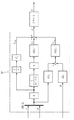
本発明の一実施形態を、図面を参照して説明する。図1に示すものは、本発明の適用対象の一であるEGRシステムである。内燃機関2に付帯するこのEGRシステムは、吸排気系3、4における複数の流体圧または流量に関する値を検出するための計測器11、12と、それらの値に目標値を設定し、各値を目標値に追従させるべく複数の操作部45、42、33を操作する制御装置たるECU5とを具備してなる。
An embodiment of the present invention will be described with reference to the drawings. What is shown in FIG. 1 is an EGR system that is one of the objects to which the present invention is applied. The EGR system incidental to the
内燃機関2は、例えば過給機を備えたディーゼルエンジンである。内燃機関2の吸気系3には、可変ターボのコンプレッサ31を配設するとともに、その下流に吸気冷却用のインタークーラ32、及び新気量を調節するDスロットルバルブ33を設ける。また、新気量を計測する流量計11、吸気管内圧力を計測する圧力計12をそれぞれ設置する。
The
内燃機関2の排気系4には、コンプレッサ31を駆動するタービン41を配設し、タービン41の入口には過給機のA/R比を増減させるためのノズルベーン42を設ける。タービン41の下流には、DPF(Diesel Particulate Filter)(図示せず)を設置する。そして、内燃機関2の燃焼室より排出される排気ガスの一部を吸気系3に還流させるEGR通路43を形成する。EGR通路43は、吸気系3におけるスロットルバルブ33よりも下流に接続する。EGR通路43には、排気冷却用のEGRクーラ44と、通過する排気ガス(EGRガス)量を調節する外部EGRバルブ45とを設ける。
The exhaust system 4 of the
本実施形態では、EGR率(または、EGR量)と、吸気管内圧力(または、吸気量)とについて各々目標値を設定し、双方の制御量を一括に目標値に向かわせるべく複数の操作部、即ちEGRバルブ45、可変ターボのノズル42及びスロットルバルブ33を操作する制御を実施する。
In the present embodiment, a target value is set for each of the EGR rate (or EGR amount) and the intake pipe pressure (or intake air amount), and a plurality of operation units are set so that both control amounts are directed toward the target value. That is, control for operating the
EGRバルブ45、ノズルベーン42、スロットルバルブ33は、ECU5により統御されてその開度をリニアに変化させる。各操作部45、42、33は、駆動信号のデューティ比を増減させることで開度を変える電気式のバルブや、あるいはバキュームコントロールバルブ等と組み合わされ弁体のリフト量を制御して開度を変える機械式のバルブ等を用いてなる。
The
ECU5は、プロセッサ、RAM(Random Access Memory)、ROM(Read Only Memory)またはフラッシュメモリ、A/D変換回路、D/A変換回路等を包有するマイクロコンピュータである。ECU5は、EGR率及び吸気管内圧力を検出するための計測器11、12の他、エンジン回転数、アクセルペダルの踏込量、冷却水温、吸気温、外部の気温、大気圧、DPFの前後差圧(DPFの上流側排気圧と下流側排気圧との差)等を検出する各種計測器(図示せず)と電気的に接続し、これら計測器から出力される信号を受け取って各値を知得することができる。
The ECU 5 is a microcomputer including a processor, a RAM (Random Access Memory), a ROM (Read Only Memory) or a flash memory, an A / D conversion circuit, a D / A conversion circuit, and the like. In addition to the
因みに、本実施形態では、EGR率を直接計測していない。内燃機関2のシリンダに入る空気量は、可変ターボのノズル開度を基に予測することが可能である。その空気量の予測値をgcylとおき、流量計11で計測される新気量をgaとおくと、推定EGR率eegrについて、eegr=1−ga/gcylなる関係が成立する。ECU5のROMまたはフラッシュメモリには予め、可変ターボのノズル開度とシリンダに入る空気量との関係を定めたマップデータが記憶されている。ECU5は、可変ターボのノズル開度をキーとしてマップを検索し、シリンダに入る空気量の予測値を得、これと新気量とを上記式に代入してEGR率を算出する。
Incidentally, in this embodiment, the EGR rate is not directly measured. The amount of air entering the cylinder of the
並びに、ECU5は、EGRバルブ45、可変ターボのノズル42、スロットルバルブ33や、燃料噴射を司るインジェクタ及び燃料ポンプ等(図示せず)と電気的に接続しており、これらを駆動するための信号を入力することができる。
In addition, the ECU 5 is electrically connected to the
ECU5で実行するべきプログラムはROMまたはフラッシュメモリに予め記憶されており、その実行の際にRAMへ読み込まれ、プロセッサによって解読される。ECU5は、プログラムに従い内燃機関2を制御する。例えば、エンジン回転数、アクセルペダルの踏込量、冷却水温等の諸条件に基づき要求される燃料噴射量(いわば、要求されるエンジン負荷)を決定し、その要求噴射量に対応する駆動信号をインジェクタ等に入力して燃料噴射を制御する。その上で、ECU5は、プログラムに従い、図2、図3に示すサーボコントローラ51及び補正制御部52としての機能を発揮する。
A program to be executed by the
サーボコントローラ51は、スライディングモードコントローラであって、EGR率及び吸気管内圧力のスライディングモード制御を担う。フィードバック制御時、ECU5は、各種計測器(図示せず)が出力する信号を受け取ってエンジン回転数、アクセル踏込量、冷却水温、吸気温、外部の気温及び気圧等を知得し、要求噴射量を決定する。続いて、少なくともエンジン回転数及び要求噴射量に基づき、目標EGR率及び目標吸気管内圧力を設定する。ECU5のROMまたはフラッシュメモリには予め、エンジン回転数及び要求噴射量に応じて設定するべき各目標値を示すマップデータが記憶されている。ECU5は、エンジン回転数及び要求噴射量をキーとしてマップを検索し、EGR率及び吸気管内圧力の目標値を得る。さらに、マップを参照して得た目標値を基本値とし、これを冷却水温、吸気温、外部の気温や気圧等に応じて補正して最終的な目標値とする。
The
そして、ECU5は、計測器11、12が出力する信号を受け取ってEGR率及び吸気管内圧力の現在値を知得し、各制御量の現在値と目標値との偏差からEGRバルブ45の開度、可変ターボのノズル42の開度及びスロットルバルブ33の開度を演算して、各々の操作量に対応する駆動信号をそれら操作部45、42、33に入力、開度を操作する。
Then, the
EGR率の適応スライディングモード制御に関して補記する。状態方程式及び出力方程式は、下式(数1)の通りである。 A supplementary explanation will be given regarding adaptive sliding mode control of the EGR rate. The state equation and the output equation are as shown in the following equation (Equation 1).

本実施形態では、状態量ベクトルXを出力ベクトルYから直接知得できる構造とする、換言すれば計測器11、12を介して検出可能な値を直接の制御対象とすることにより、状態推定オブザーバを排して推定誤差に伴う制御性能の低下を予防している。出力行列Cは既知、本実施形態では単位行列とする。
In this embodiment, the state quantity vector X has a structure that can be directly obtained from the output vector Y. In other words, a value that can be detected via the measuring
プラントのモデル化、即ち状態方程式(数1)における係数行列A及び入力行列Bの同定にあたっては、各操作部45、42、33に様々な周波数からなるM系列信号を入力して開度を操作し、EGR率及び吸気管内圧力の値を観測して、その入出力データから行列A、Bを同定する。各操作部45、42、33に入力するM系列信号は、互いに無相関なものとする。これにより、各値の相互干渉を考慮したモデルを作成することができる。
In plant modeling, that is, identification of the coefficient matrix A and the input matrix B in the state equation (Equation 1), the opening degree is manipulated by inputting M-sequence signals having various frequencies to the
図3に、本実施形態の適応スライディングモード制御系のブロック線図を示す。スライディングモードコントローラ51の設計手順には、切換超平面の設計と、状態量を切換超平面に拘束するための非線形切換入力の設計とが含まれる。1形のサーボ系を構成するべく、当初の状態量ベクトルXに、目標値ベクトルRと出力ベクトルYとの偏差の積分値ベクトルZを付加した新たな状態量ベクトルXeを定義すると、下式(数2)に示す拡大系の状態方程式を得る。
FIG. 3 shows a block diagram of the adaptive sliding mode control system of the present embodiment. The design procedure of the sliding
安定余裕を考慮し、切換超平面の設計にはシステムの零点を用いた設計手法を用いる。即ち、上式(数2)の拡大系がスライディングモードを生じているときの等価制御系が安定となるように超平面を設計する。切換関数σを式(数3)で定義すると、状態が超平面に拘束されている場合にσ=0かつ式(数4)が成立する。 In consideration of the stability margin, the design method using the zero of the system is used to design the switching hyperplane. That is, the hyperplane is designed so that the equivalent control system is stable when the expansion system of the above equation (Equation 2) is generating the sliding mode. When the switching function σ is defined by Expression (Expression 3), σ = 0 and Expression (Expression 4) holds when the state is constrained to the hyperplane.
![]()
![]()
故に、スライディングモードが生じているときの線形入力(等価制御入力)は、下式(数5)となる。 Therefore, the linear input (equivalent control input) when the sliding mode occurs is expressed by the following equation (Equation 5).
上式(数5)の線形入力を拡大系の状態方程式(数2)に代入すると、下式(数6)の等価制御系となる。 Substituting the linear input of the above equation (Equation 5) into the state equation (Equation 2) of the expanded system results in an equivalent control system of the following equation (Equation 6).
この等価制御系が安定になるように超平面を設計することと、目標値Rを無視した系に対して設計することとは等価であるので、下式(数7)が成立する。 Since designing a hyperplane so that this equivalent control system is stable is equivalent to designing a system ignoring the target value R, the following equation (Equation 7) holds.
上式(数7)の系に対して安定度εを考慮し、最適制御理論を用いてフィードバックゲインを求め、それを超平面とすると、下式(数8)となる。 Taking the stability ε into consideration for the system of the above equation (Equation 7), obtaining the feedback gain using the optimal control theory, and making it a hyperplane, the following equation (Equation 8) is obtained.
行列Psは、リカッチ方程式(数9)の正定解である。 The matrix P s is a positive definite solution of the Riccati equation (Equation 9).
リカッチ方程式(数9)におけるQsは制御目的の重み行列で、非負定な対称行列である。q1、q2は偏差の積分Zに対する重みであり、制御系の周波数応答の速さの違いにより決定する。q3、q4は出力Yに対する重みであり、ゲインの大きさの違いにより決定する。また、リカッチ方程式(数9)におけるRsは制御入力の重み行列で、正定対称行列である。εは安定余裕係数で、ε≧0となるように指定する。 Q s in the Riccati equation (Equation 9) is a weight matrix for control purposes, and is a non-negative definite symmetric matrix. q 1 and q 2 are weights for the integral Z of the deviation, and are determined by the difference in the speed of the frequency response of the control system. q 3 and q 4 are weights for the output Y, and are determined by the difference in the magnitude of the gain. Further, R s in the Riccati equation (Equation 9) is a weight matrix of the control input and is a positive definite symmetric matrix. ε is a stability margin coefficient and is specified so that ε ≧ 0.
なお、上記式(数8)、(数9)に替えて、以下に示す離散系の超平面構築式(数10)及び代数リカッチ方程式(数11)を用いてもよい。 Instead of the above equations (Equation 8) and (Equation 9), the following discrete hyperplane construction equation (Equation 10) and algebraic Riccati equation (Equation 11) may be used.
![]()
![]()
![]()
![]()
超平面に拘束するための入力の設計には、最終スライディングモード法を用いる。ここでは、制御入力Uを、線形入力Ueqと新たな入力即ち非線形入力(非線形制御入力)Unlとの和として、下式(数12)で表す。 The final sliding mode method is used to design the input for constraining to the hyperplane. Here, the control input U is expressed by the following expression (Equation 12) as the sum of the linear input U eq and a new input, that is, a nonlinear input (nonlinear control input) U nl .
切換関数σを安定させたいので、σについてのリアプノフ関数を下式(数13)のように選び、これを微分すると式(数14)となる。 Since it is desired to stabilize the switching function σ, the Lyapunov function for σ is selected as shown in the following equation (Equation 13) and differentiated to obtain the equation (Equation 14).
式(数12)を式(数14)に代入すると、下式(数15)となる。 Substituting the equation (Equation 12) into the equation (Equation 14) yields the following equation (Equation 15).
![]()
![]()
非線形入力Unlを下式(数16)とすると、リアプノフ関数の微分は式(数17)となる。 When the nonlinear input U nl to the following expression (Expression 16), the derivative of the Lyapunov function becomes equation (17).
従って、切換ゲインkを正とすれば、リアプノフ関数の微分値を負とすることができ、スライディングモードの安定性が保証される。このときの制御入力Uは、下式(数18)である。 Therefore, if the switching gain k is positive, the differential value of the Lyapunov function can be negative, and the stability of the sliding mode is guaranteed. The control input U at this time is expressed by the following equation (Equation 18).
ηはチャタリング低減のために導入した平滑化係数であって、η>0である。 η is a smoothing coefficient introduced to reduce chattering, and η> 0.
スライディングモード制御では、状態量を超平面に拘束するために非線形ゲインを大きくする必要がある。だが、非線形ゲインを大きくすると、制御入力にチャタリングが発生する。そこで、モデルの不確かさを、構造が既知でパラメータが未知な確定部分と、構造が未知だがその上界値が既知な不確定部分とに分ける。状態方程式(数1)に不確かさ(f+Δf)を加え、下式(数19)で表す。 In the sliding mode control, it is necessary to increase the nonlinear gain in order to constrain the state quantity to the hyperplane. However, if the nonlinear gain is increased, chattering occurs in the control input. Therefore, the uncertainty of the model is divided into a definite part whose structure is unknown and whose parameter is unknown, and an uncertain part whose structure is unknown but whose upper bound is known. Uncertainty (f + Δf) is added to the state equation (Equation 1), and is expressed by the following equation (Equation 19).
不確かさの確定部分fは、未知パラメータθを同定することで補償される。さすれば、切換ゲインは不確かさの不確定部分Δfのみにかかることとなり、切換ゲインが不確実成分全体(f+Δf)にかかる場合と比べて制御入力のチャタリングを大幅に低減できる。 The uncertainty determination part f is compensated by identifying the unknown parameter θ. In this case, the switching gain is applied only to the uncertain part Δf of the uncertainty, and the chattering of the control input can be greatly reduced as compared with the case where the switching gain is applied to the entire uncertain component (f + Δf).
制御入力Uは、式(数18)に適応項Uadを追加した下式(数20)となる。 The control input U is represented by the following equation (Equation 20) obtained by adding the adaptive term U ad to the equation (Equation 18).
制御入力(数20)におけるΓ1は、適応ゲイン行列である。関数hは、一般には状態量x及び/または未知パラメータθの関数とするが、本実施形態ではhをx及びθに無関係な単純式、定数とすることにより、xを速やかに収束させ、θの適応速度を高めるようにしている。特に、h=1とした場合、推定パラメータを下式(数21)に則って同定することができる。 Γ 1 at the control input (Equation 20) is an adaptive gain matrix. The function h is generally a function of the state quantity x and / or the unknown parameter θ. However, in the present embodiment, by making h a simple expression and a constant unrelated to x and θ, x is quickly converged, and θ To increase the adaptation speed. In particular, when h = 1, the estimated parameter can be identified according to the following equation (Equation 21).
本実施形態では、EGR率y1及び吸気管内圧力y2を制御出力変数とし、EGRバルブ45の開度u1、可変ターボのノズル42の開度u2及びスロットルバルブ33の開度u3を制御入力変数とした3入力2出力のフィードバック制御を行う。状態変数の個数(システムの次数)は、当初の系(数1)では出力変数の個数と同じく2、拡大系(数2)では4となる。制御出力及び状態量をこのように特定することで、排気ガスに直接触れる箇所に流量計等の計測器を設置する必要がなくなる。
In the present embodiment, the EGR ratio y 1 and the intake pipe pressure y 2 as a control output variable, the opening degree u 1 of the
尤も、本実施形態のような3入力2出力のシステムでは、det(SBe)=0が成立し、行列(SBe)は正則とはならない。そこで、逆行列(SBe)-1を、一般化逆行列として算定する。一般化逆行列には、例えばムーア・ペンローズ型の逆行列(SBe)†を用いる。 However, in a three-input two-output system as in this embodiment, det (SB e ) = 0 holds, and the matrix (SB e ) is not regular. Therefore, the inverse matrix (SB e ) −1 is calculated as a generalized inverse matrix. As the generalized inverse matrix, for example, a Moore-Penrose-type inverse matrix (SB e ) † is used.
しかして、補正制御部52は、内燃機関2の現況に応じた制御の切り換えを司る。本実施形態では、内燃機関2の運転領域の区分として、少なくとも下記の四種を想定している。
Thus, the
(i)NA域(負圧域、無過給域);アイドル運転のような低負荷領域、即ちエンジン回転数もトルクも低い領域である。NA域では、吸気管内圧力はおおよそ大気圧に近い大きさとなる。このとき、ノズルベーン42の開度を幾ら変えても排気ターボ過給機が仕事をしてくれない状態になる。そして、吸気管内圧力の目標値が吸気管内圧力の実測値より少しでも高いと、ノズル開度が絞られ、ついには飽和(極小化)してそれ以上ノズル開度が変化しなくなる。となれば、排気ガス浄化能率の維持に重要なEGR率の制御に支障を来たしてしまいかねない。
(I) NA region (negative pressure region, no supercharging region); a low load region such as idle operation, that is, a region where the engine speed and torque are low. In the NA region, the pressure in the intake pipe is approximately close to atmospheric pressure. At this time, the exhaust turbocharger does not work even if the opening degree of the
(ii)EGRカット域;EGR通路43を経由したEGRガスの還流を停止する領域である。高い出力トルクが必要とされる高回転高負荷領域や、燃焼不安定ないし失火のおそれのある高地(大気圧が低い状況)にてある程度以上の負荷運転を行うとき、暖気運転を要するとき等が、EGRカット域に該当する。
(Ii) EGR cut region: This is a region where the recirculation of EGR gas via the
(iii)EGRカットNA域;やはり、EGR通路43を経由したEGRガスの還流を停止する領域である。EGRカット域との相異は、EGRカット域ではノズルベーン42の開閉操作を通じて吸気管内圧力を増減させ得るのに対し、EGRカットNA域ではそうではない点にある。例えば、DPFの再生を行うときや、高地にて低負荷低回転運転を行うとき等が、EGRカットNA域に該当する。前者においては、(DPFに捕集しているPM(Particulate Matter)を酸化させて除去する目的で)ポスト噴射等を伴いつつ高温の排気ガスをどんどんDPFに送り込みDPFの温度を高めなければならないので、吸気管内圧力制御の目的でノズルベーン42の開度を絞りたくない。また、後者においては、燃焼不安定ないし失火を予防するべくEGRをカットするが、元々排気ガス量が少なく排気圧も低いために、NA域と同様に排気ターボ過給機が仕事をしてくれないという事情がある。
(Iii) EGR cut NA area: This is also an area where the recirculation of the EGR gas via the
(iv)ノーマル域;上記の何れにも該当せず、内燃機関2の制御をスライディングモードコントローラ51に完全に委ねてよい領域である。
(Iv) Normal region: This is a region that does not fall under any of the above, and may completely entrust the control of the
補正制御部52は、エンジン回転数及び要求燃料噴射量(要求負荷)、冷却水温、大気圧、DPFの前後差圧等に基づいて、現在の内燃機関2の運転領域区分を判断する。
The
図4に、エンジン回転数及び燃料噴射量と運転領域との関係を示す。原則として、エンジン回転数及び燃料噴射量がそれぞれ閾値L1よりも低い低回転低負荷の領域をNA域、エンジン回転数及び燃料噴射量がそれぞれ閾値L2よりも高い高回転高負荷の領域をEGRカット域とし、それ以外の領域をノーマル域とする。 FIG. 4 shows the relationship between the engine speed and the fuel injection amount and the operation region. In principle, the low rotation and low load areas where the engine speed and the fuel injection amount are each lower than the threshold value L 1 are NA areas, and the high rotation and high load areas where the engine speed and the fuel injection quantity are each higher than the threshold value L 2. The EGR cut area is set, and the other area is set as the normal area.
但し、大気圧が閾値よりも低く、自動車が高地に所在していると考えられる状況下では、低回転低負荷の領域をEGRカットNA域とし、中回転以上または中負荷以上の領域をEGRカット域とする。 However, in situations where the atmospheric pressure is lower than the threshold value and the automobile is considered to be located at high altitude, the low-rotation and low-load area is set as the EGR cut NA area, and the medium-rotation or higher area and Eload-cut area are EGR cut. A zone.
また、冷却水温が所定値(典型的には、40℃)を下回っているときには、暖機運転のためにEGRカット域とする。並びに、DPFの前後差圧が所定値を越えているときには、DPF再生のためにEGRカットNA域とする。 Further, when the cooling water temperature is lower than a predetermined value (typically 40 ° C.), the EGR cut region is set for warm-up operation. When the differential pressure across the DPF exceeds a predetermined value, the EGR cut NA region is set for DPF regeneration.
次いで、補正制御部52は、判断した運転領域区分に応じて、非線形入力項Unlを規定する切換ゲインk及び/または平滑化係数ηを変更する。
Next, the
既に述べた通り、スライディングモードコントローラ51を設計する際には、特定の運転領域、即ちあるエンジン回転数及び要求燃料噴射量の下における内燃機関2のノミナルモデル(行列A、B)を同定し、状態方程式(数2)を得て切換超平面Sを導出している。このノミナルモデルと実プラントとの間のモデル化誤差(摂動)は、ノーマル域では比較的小さいが、それ以外の領域では拡大する。そこで、本実施形態では、NA域、EGRカット域、EGRカットNA域及びノーマル域という各領域区分毎に、相異なる切換ゲインk及び/または平滑化係数ηを設定することとして、摂動の抑制を図っている。
As already described, when designing the sliding
ECU5のROMまたはフラッシュメモリには予め、図4に示しているような、各領域区分と、切換ゲインk及び/または平滑化係数ηとの関係を定めたマップが記憶されている。補正制御部52は、このマップデータを参照して、k及び/またはηを決定する。即ち、内燃機関2またはそれに付帯する装置の現在状況に関する指標値(エンジン回転数及び燃焼噴射量、冷却水温、大気圧、DPFの前後差圧等)をキーとしてマップを検索し、設定するべきk及び/またはηを知得する。
The ROM or flash memory of the
さらに、補助制御部52は、NA域、EGRカット域、EGRカットNA域、ノーマル域の間で領域区分の遷移が発生した場合において、スライディングモードコントローラ51が算出する非線形入力Unlがステップ的に急変動しないよう、k及び/またはηを変更した後の非線形入力Unlとその変更をする前の非線形入力Unlとが同値となるような状態変数Xeを逆算し、状態変数Xeを書き換える。
Further, the
因数JΣを下式(数22)とおくと、非線形入力Unlは一般化逆行列(−(SBe)†)にこの因数JΣを乗じたものとなる。 Placing the factor Jshiguma the following expression (Expression 22), the nonlinear input U nl generalized inverse matrix - a ((SB e) †) in multiplied by the factor Jshiguma.
図5に、切換関数σと因数JΣとの関係を模式的に例示する。本実施形態において、σ及びJΣはともに3次元ベクトルであるので、図5は数学的に正確ではない。が、敢えてこの図5に則して述べる(あるいは、σ及びJΣをともにスカラ値と考える)と、JΣはσが増大するにつれて切換ゲインkに漸近する。また、JΣが漸近線kへと近づく変化は、平滑化係数ηが小さいほど急速になり、ηが小さいほど緩慢になる。 FIG. 5 schematically illustrates the relationship between the switching function σ and the factor JΣ. In this embodiment, since σ and JΣ are both three-dimensional vectors, FIG. 5 is not mathematically accurate. However, if it is described with reference to FIG. 5 (or σ and JΣ are both considered as scalar values), JΣ gradually approaches the switching gain k as σ increases. Further, the change in which JΣ approaches the asymptotic line k becomes more rapid as the smoothing coefficient η is smaller, and becomes slower as η is smaller.
k及び/またはηの変更後と変更前とで非線形入力Unlが変動しないようにするためには、その変更後と変更前とでJΣが同値にならなければいけない。従って、下式(数23)が成立する必要がある。 For k and / or non-linear input U nl between before and after the change of η is prevented from variation, Jshiguma in as before and after the change must not to be become equivalent. Therefore, the following equation (Equation 23) needs to be established.
JΣn-1、σn-1、kn-1、ηn-1はそれぞれ、運転領域の区分が遷移する直前の時点における因数、切換関数、切換ゲイン、平滑化係数である。同様に、JΣn、σn、kn、ηnはそれぞれ、運転領域の区分が遷移した直後の時点における因数、切換関数、切換ゲイン、平滑化係数である。図6に、NA域からノーマル域に遷移する場合を例示している。 JΣ n−1 , σ n−1 , k n−1 , and η n−1 are a factor, a switching function, a switching gain, and a smoothing coefficient at a point just before the transition of the operation region. Similarly, JΣ n , σ n , k n , and η n are a factor, a switching function, a switching gain, and a smoothing coefficient at the time immediately after the operation region section is changed. FIG. 6 shows an example of transition from the NA area to the normal area.
式(数23)を変形すると、式(数24)となる。 When formula (Formula 23) is transformed, Formula (Formula 24) is obtained.
因数ベクトルJΣn-1=[jσ1 jσ2 jσ3]T、切換関数ベクトルσn=[σn1 σn2 σn3]Tとすると、因数ベクトルJΣn-1の各成分jσi(i=1,2,3)について、jσi>0であれば式(数25)が、jσi≦0であれば式(数26)が成立する。
If the factor vector JΣ n−1 = [jσ 1 jσ 2 jσ 3 ] T and the switching function vector σ n = [σ n1 σ n2 σ n3 ] T , each component jσ i (i = 1) of the
式(数25)を変形すれば式(数27)となり、式(数26)を変形すれば式(数28)となる。 If Formula (Formula 25) is modified, Formula (Formula 27) is obtained, and if Formula (Formula 26) is modified, Formula (Formula 28) is obtained.
式(数27)ないし(数28)により、因数JΣひいては非線形入力Unlの変動を招かないような切換関数σnが明らかとなる。この切換関数σnから、状態量Xeを逆算することを試みる。 Expressions (Equation 27) to (Equation 28) reveal the switching function σ n that does not cause the variation of the factor JΣ and hence the nonlinear input U nl . An attempt is made to back-calculate the state quantity X e from this switching function σ n .
状態量ベクトルXe=[xe1 xe2 xe3 xe4]Tは、その成分に、制御出力Yとその目標値Rとの偏差の時間積分xe1、xe2と、それ以外のものxe3、xe4とを含んでいる。xe1及びxe3は第一の制御出力たるEGR率y1に係り、xe2及びxe4は第二の制御出力たる吸気管内圧力y2に係り、これら状態変数xe1及びxe3、xe2及びxe4は各制御出力y1、y2毎に個別のものとなっている。また、xe3、xe4は出力方程式(数1)を介して各制御出力y1、y2とそれぞれ結びついている。 The state quantity vector X e = [x e1 x e2 x e3 x e4 ] T has, as its components, time integrals x e1 and x e2 of deviation between the control output Y and its target value R, and other x e3 , X e4 . x e1 and x e3 relate to the EGR rate y 1 as the first control output, x e2 and x e4 relate to the intake pipe pressure y 2 as the second control output, and these state variables x e1 and x e3 , x e2 And x e4 are individual for each control output y 1 , y 2 . Further, x e3 and x e4 are respectively connected to the control outputs y 1 and y 2 via the output equation (Equation 1).
式(数3)より、切換関数σnと状態量xeとの間には下式(数29)の関係が成立する。 From the equation (Equation 3), the relationship of the following equation (Equation 29) is established between the switching function σ n and the state quantity x e .
Sj(j=1,2,3,4)は,切換超平面を構成する行列Sの成分のうち,状態変数xejに乗ずる列ベクトルである。 S j (j = 1, 2, 3, 4) is a column vector to be multiplied by the state variable x ej among the components of the matrix S constituting the switching hyperplane.
上式(数29)から、切換関数σnを実現する状態変数xe1、xe2、xe3、xe4を逆算することができる。但し、本実施形態では、xe3はEGR率そのものであり、xe4は吸気管内圧力そのものである。また、状態変数xe1及びxe2は、非線形入力Unlに影響を及ぼすが、線形入力Ueqには影響を及ぼさない(行列Aeの定義に留意)。それ故、状態変数xe3及びxe4を書き換えることはせず、状態変数xe1及びxe2を書き換えることによって式(数27)ないし(数28)に示している切換関数σnを実現、非線形入力Unlの変動を阻止する。そのために必要となるxe1及びxe2は、下式(数30)となる。 From the above equation (Equation 29), the state variables x e1 , x e2 , x e3 , x e4 that realize the switching function σ n can be calculated backward. However, in this embodiment, x e3 is the EGR rate itself, and x e4 is the intake pipe pressure itself. The state variables x e1 and x e2 affect the nonlinear input U nl , but do not affect the linear input U eq (note the definition of the matrix A e ). Therefore, the state variables x e3 and x e4 are not rewritten, and the switching functions σ n shown in the equations (Equation 27) to (Equation 28) are realized by rewriting the state variables x e1 and x e2. Prevent fluctuations in the input Unl . The x e1 and x e2 required for this are given by the following equation (Equation 30).
尤も、行列[S1 S2]は正方行列ではない。そこで、逆行列[S1 S2]-1を、一般化逆行列として算定する。一般化逆行列には、例えばムーア・ペンローズ型の逆行列[S1 S2]†を用いる。 However, the matrix [S 1 S 2 ] is not a square matrix. Therefore, the inverse matrix [S 1 S 2 ] −1 is calculated as a generalized inverse matrix. As the generalized inverse matrix, for example, a Moore-Penrose-type inverse matrix [S 1 S 2 ] † is used.
加えて、補正制御部52は、現在の運転領域がNA域、EGRカット域またはEGRカットNA域にあると判断した場合に、それぞれの領域毎に所要の補正を施す。
In addition, when it is determined that the current operation region is in the NA region, the EGR cut region, or the EGR cut NA region, the
NA域においては、ノズルベーン42の開度をスライディングモードコントローラ51が算出する制御入力値u2によらない所定値に固定する。それとともに、吸気管内圧力の実測値y2及びxe4として、吸気管内圧力の目標値r2をスライディングモードコントローラ51に与える。スライディングモードコントローラ51内では、吸気管内圧力の偏差が0であると見なされる。
In the NA region, the opening degree of the
EGRカット域においては、EGRバルブ45の開度をスライディングモードコントローラ51が算出する制御入力値u1を無視して全閉し、なおかつ、Dスロットルバルブの開度をスライディングモードコントローラ51が算出する制御入力値u3を無視して全開する。それとともに、EGR率の実測値y1及びxe3として、EGR率の目標値r1をスライディングモードコントローラ51に与える。スライディングモードコントローラ51内では、EGR率の偏差が0であると見なされる。
In the EGR cut region, the control input value u 1 calculated by the sliding
EGRカットNA域においては、EGRバルブ45の開度をスライディングモードコントローラ51が算出する制御入力値u1を無視して全閉する。それとともに、EGR率の実測値y1及びxe3として、EGR率の目標値r1をスライディングモードコントローラ51に与える。スライディングモードコントローラ51内では、EGR率の偏差が0であると見なされる。なお、ノズルベーン42については、スライディングモードコントローラ51が算出する制御入力値u2をそのまま与えて操作してもよいし、その開度を制御入力値u2によらない所定値に固定してもよい。
In the EGR cut NA region, the control input value u 1 calculated by the sliding
ノーマル域においては、これらの如き補正を行わない。 These corrections are not performed in the normal range.
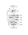
図7に、ECU5が実行する処理の手順例を示す。ECU5は、エンジン回転数及び要求燃料噴射量、冷却水温、大気圧、DPFの前後差圧等を参照して、NA域/EGRカット域/EGRカットNA域/ノーマル域の間で領域の遷移が発生したか否かを判断する(ステップS1)。領域の遷移が発生したと判断したならば、エンジン回転数及び要求燃料噴射量等に基づいて設定するべき切換ゲインk及び/または平滑化係数ηを知得し(ステップS2)、そのk及び/またはηの設定変更後の切換関数σnがその設定変更直前のσn-1に等しくなるような状態変数xe1、xe2を逆算する(ステップS3)。そして、ECU5のメモリに記憶保持しているk及び/またはη、xe1、xe2の書き換えを行う(ステップS4)。領域の遷移が発生しなければ、ステップS2ないしS4を実施しないことは言うまでもない。
In FIG. 7, the example of a procedure of the process which ECU5 performs is shown. The
その上で、スライディングモード制御の手法に則り、制御入力Uを算出する(ステップS5)。しかる後、算出した制御入力Uを操作部45、42、33に与えてこれらを操作する(ステップS6)。但し、現在の運転領域がNA域、EGRカット域またはEGRカットNA域にある場合には、ステップS5にて本来のEGR率または吸気管内圧力とは異なる値をスライディングモードコントローラ51に与えるとともに、ステップS6にてスライディングモードコントローラ51の演算結果を無視してEGRバルブ45、ノズルベーン42またはDスロットルバルブ33を操作する。
Then, the control input U is calculated in accordance with the sliding mode control method (step S5). Thereafter, the calculated control input U is given to the
ECU5は、上記のステップS1ないしS6を、反復的に実施する。
The
本実施形態によれば、内燃機関2またはこれに付帯する装置をスライディングモード制御するものであって、状態変数Xeを参照して線形入力Ueq及び非線形入力Unlを反復的に演算するスライディングモードコントローラ51と、所定条件に応じて前記非線形入力Unlを規定する切換ゲインk及び平滑化係数ηのうち一方または両方を変更するとともに、その変更をした後の非線形入力Unlがその変更をする前の非線形入力Unlと同値となるような状態変数Xeを逆算して状態変数Xeを書き換える補正制御部52とを具備する制御装置5を構成したため、切換ゲインk及び/または平滑化係数ηの適宜変更を通じてプラントの入出力特性の変化に追随し、摂動の過大化を防止することができる。従って、低回転低負荷域、高回転高負荷域等においても制御性能が劣化せず、一時的な排気ガスの悪化や出力トルクの低下を抑制ないし回避することが可能となる。
According to this embodiment, the
前記補正制御部52が、内燃機関2またはそれに付帯する装置の現在状況に関する指標値と、前記切換ゲインkまたは前記平滑化係数ηとの関係を定めたマップを予め記憶しており、前記指標値をキーとして当該マップを検索することを通じて変更後の切換ゲインkまたは平滑化係数ηを知得するものであるため、切換ゲインk及び/または平滑化係数ηを変更する際にECU5に余計な演算負荷をかけずに済む。
The
なお、本発明は以上に詳述した実施形態に限られるものではない。特に、ある領域から他の領域へと遷移するときに、どうしてもJΣを一定に保つことができないケースが発生し得る。例えば、各領域毎に切換ゲインkの大きさが異なっている場合、kが比較的大きい領域からkが比較的小さい領域へと遷移する際に一致するJΣが存在しないことがある。このような問題への対処法としては、下記の二通りが考えられる。 The present invention is not limited to the embodiment described in detail above. In particular, when transitioning from one region to another region, there may occur a case where JΣ cannot be kept constant. For example, when the magnitude of the switching gain k is different for each region, there may be no matching JΣ when transitioning from a region where k is relatively large to a region where k is relatively small. There are two possible ways to deal with such problems.
(I)各領域毎のkを統一する;図8に示すように、全ての領域のkを同一値とすれば、どの領域においても必ず同じJΣが存在する。領域の遷移が発生したときには、平滑化係数ηのみを変更する。 (I) Unify k for each region; as shown in FIG. 8, if all regions have the same value k, the same JΣ always exists in any region. When the region transition occurs, only the smoothing coefficient η is changed.
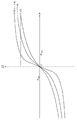
(II)切換関数σの上下限を設定する;図9に示すように、全ての領域でJΣが存在するようなσの上限σmax、下限σminを定めておく。σがこれら閾値σmaxまたはσminを超越してしまう暁には、σをσmaxまたはσminにクリップする。 (II) The upper and lower limits of the switching function σ are set; as shown in FIG. 9, the upper limit σ max and the lower limit σ min of σ such that JΣ exists in all regions are determined. When σ exceeds these thresholds σ max or σ min , σ is clipped to σ max or σ min .
また、EGR制御における制御入力変数は、EGRバルブ開度、可変ノズルターボ開度及びスロットルバルブ開度には限定されない。制御出力変数も、EGR率(または、EGR量)及び吸気管内圧力(または、吸気量)には限定されない。新たな入力変数、出力変数を付加して、4入力3出力の3次システムを構築するようなことも可能である。例えば、吸気系に過給機(のコンプレッサ)をバイパスする通路が存在している場合、その通路上に設けられたバルブをも操作することがある。このとき、当該バイパス通路内の圧力または流量等を制御出力変数に含め、当該バイパス通路上のバルブの開度を制御入力変数に含めることができる。 Further, the control input variables in the EGR control are not limited to the EGR valve opening, the variable nozzle turbo opening, and the throttle valve opening. The control output variable is not limited to the EGR rate (or EGR amount) and the intake pipe pressure (or intake amount). It is also possible to construct a tertiary system with four inputs and three outputs by adding new input variables and output variables. For example, when a passage that bypasses the supercharger (compressor) is present in the intake system, a valve provided on the passage may be operated. At this time, the pressure or flow rate in the bypass passage can be included in the control output variable, and the opening of the valve on the bypass passage can be included in the control input variable.
その他各部の具体的構成は、本発明の趣旨を逸脱しない範囲で種々変形が可能である。 Other specific configurations of each part can be variously modified without departing from the spirit of the present invention.
本発明は、例えば、過給機及びEGR装置が付帯した内燃機関のEGR率を制御するための制御コントローラとして利用することができる。 The present invention can be used, for example, as a control controller for controlling the EGR rate of an internal combustion engine attached with a supercharger and an EGR device.
5…ECU(制御装置)
51…適応スライディングモードコントローラ
52…補正制御部
5 ... ECU (control device)
51 ... Adaptive sliding
Claims (2)
状態変数を参照して線形入力及び非線形入力を反復的に演算するスライディングモードコントローラと、
所定条件に応じて前記非線形入力を規定する切換ゲイン及び平滑化係数のうち一方または両方を変更するとともに、その変更をした後の非線形入力がその変更をする前の非線形入力と同値となるような状態変数を逆算して状態変数を書き換える補正制御部と
を具備することを特徴とする制御装置。 A sliding mode control of an internal combustion engine or a device attached thereto,
A sliding mode controller that iteratively computes linear and nonlinear inputs with reference to state variables;
According to a predetermined condition, one or both of the switching gain and the smoothing coefficient that define the nonlinear input are changed, and the nonlinear input after the change becomes the same value as the nonlinear input before the change. A control device comprising: a correction control unit that reversely calculates the state variable and rewrites the state variable.
Priority Applications (1)
| Application Number | Priority Date | Filing Date | Title |
|---|---|---|---|
| JP2009193655A JP5276552B2 (en) | 2009-08-24 | 2009-08-24 | Control device |
Applications Claiming Priority (1)
| Application Number | Priority Date | Filing Date | Title |
|---|---|---|---|
| JP2009193655A JP5276552B2 (en) | 2009-08-24 | 2009-08-24 | Control device |
Publications (2)
| Publication Number | Publication Date |
|---|---|
| JP2011043149A JP2011043149A (en) | 2011-03-03 |
| JP5276552B2 true JP5276552B2 (en) | 2013-08-28 |
Family
ID=43830730
Family Applications (1)
| Application Number | Title | Priority Date | Filing Date |
|---|---|---|---|
| JP2009193655A Expired - Fee Related JP5276552B2 (en) | 2009-08-24 | 2009-08-24 | Control device |
Country Status (1)
| Country | Link |
|---|---|
| JP (1) | JP5276552B2 (en) |
Family Cites Families (5)
| Publication number | Priority date | Publication date | Assignee | Title |
|---|---|---|---|---|
| JP2004044808A (en) * | 1997-02-27 | 2004-02-12 | Denso Corp | System control unit |
| JP2001115881A (en) * | 1999-10-19 | 2001-04-24 | Unisia Jecs Corp | Air-fuel ratio control device for internal combustion engine |
| JP2004038697A (en) * | 2002-07-05 | 2004-02-05 | Fujitsu Ltd | Positioning control device |
| JP2004143974A (en) * | 2002-10-23 | 2004-05-20 | Daihatsu Motor Co Ltd | Vehicular travel control device and control method |
| JP4638827B2 (en) * | 2006-02-28 | 2011-02-23 | ジヤトコ株式会社 | Control apparatus and control method using sliding mode control |
-
2009
- 2009-08-24 JP JP2009193655A patent/JP5276552B2/en not_active Expired - Fee Related
Also Published As
| Publication number | Publication date |
|---|---|
| JP2011043149A (en) | 2011-03-03 |
Similar Documents
| Publication | Publication Date | Title |
|---|---|---|
| JP6553580B2 (en) | Discrete time rate based model predictive control method for air path control of internal combustion engine | |
| JP2008248859A (en) | Control method and control device | |
| JP5191261B2 (en) | Servo control method and servo control device | |
| JP2011043156A (en) | Control device | |
| JP2010112307A (en) | Control device | |
| JP5460267B2 (en) | Control device | |
| JP2011043150A (en) | Control device | |
| JP5276552B2 (en) | Control device | |
| JP2010127267A (en) | Control device | |
| JP2011043152A (en) | Control device | |
| Min et al. | Iterative learning control algorithm for feedforward controller of EGR and VGT systems in a CRDI diesel engine | |
| JP5042967B2 (en) | Control device | |
| JP2011043154A (en) | Control device | |
| JP5295837B2 (en) | Control device | |
| Wahlström et al. | Nonlinear input transformation for EGR and VGT control in diesel engines | |
| JP2011043153A (en) | Control device | |
| JP5199936B2 (en) | Control device | |
| JP2011001871A (en) | Control device | |
| JP5190402B2 (en) | Control device | |
| Zeng et al. | Linear quadratic air-path control for diesel engines with regenerative and assisted turbocharger | |
| JP2011043151A (en) | Control device | |
| JP2011043155A (en) | Control device | |
| JP2010229972A (en) | Control device | |
| JP5368849B2 (en) | Control device | |
| JP5250826B2 (en) | Control device |
Legal Events
| Date | Code | Title | Description |
|---|---|---|---|
| A621 | Written request for application examination |
Free format text: JAPANESE INTERMEDIATE CODE: A621 Effective date: 20120730 |
|
| A977 | Report on retrieval |
Free format text: JAPANESE INTERMEDIATE CODE: A971007 Effective date: 20130425 |
|
| TRDD | Decision of grant or rejection written | ||
| A01 | Written decision to grant a patent or to grant a registration (utility model) |
Free format text: JAPANESE INTERMEDIATE CODE: A01 Effective date: 20130514 |
|
| A61 | First payment of annual fees (during grant procedure) |
Free format text: JAPANESE INTERMEDIATE CODE: A61 Effective date: 20130517 |
|
| R150 | Certificate of patent or registration of utility model |
Free format text: JAPANESE INTERMEDIATE CODE: R150 |
|
| LAPS | Cancellation because of no payment of annual fees |