JP5276478B2 - X-ray CT system - Google Patents
X-ray CT system Download PDFInfo
- Publication number
- JP5276478B2 JP5276478B2 JP2009050955A JP2009050955A JP5276478B2 JP 5276478 B2 JP5276478 B2 JP 5276478B2 JP 2009050955 A JP2009050955 A JP 2009050955A JP 2009050955 A JP2009050955 A JP 2009050955A JP 5276478 B2 JP5276478 B2 JP 5276478B2
- Authority
- JP
- Japan
- Prior art keywords
- ring
- ray
- frame
- rotating frame
- rotating
- Prior art date
- Legal status (The legal status is an assumption and is not a legal conclusion. Google has not performed a legal analysis and makes no representation as to the accuracy of the status listed.)
- Expired - Fee Related
Links
- 230000002093 peripheral effect Effects 0.000 claims description 19
- 230000005856 abnormality Effects 0.000 claims description 3
- 239000000463 material Substances 0.000 description 14
- 238000010586 diagram Methods 0.000 description 5
- 238000005266 casting Methods 0.000 description 3
- 239000004519 grease Substances 0.000 description 3
- 230000007547 defect Effects 0.000 description 2
- 230000002950 deficient Effects 0.000 description 2
- 239000000314 lubricant Substances 0.000 description 2
- 229910000838 Al alloy Inorganic materials 0.000 description 1
- 229910001369 Brass Inorganic materials 0.000 description 1
- 241000282412 Homo Species 0.000 description 1
- 239000010951 brass Substances 0.000 description 1
- 238000001514 detection method Methods 0.000 description 1
- 238000007689 inspection Methods 0.000 description 1
- 238000004519 manufacturing process Methods 0.000 description 1
- 229910052751 metal Inorganic materials 0.000 description 1
- 239000002184 metal Substances 0.000 description 1
- 238000000034 method Methods 0.000 description 1
- 239000011347 resin Substances 0.000 description 1
- 229920005989 resin Polymers 0.000 description 1
- BFKJFAAPBSQJPD-UHFFFAOYSA-N tetrafluoroethene Chemical group FC(F)=C(F)F BFKJFAAPBSQJPD-UHFFFAOYSA-N 0.000 description 1
- 239000013585 weight reducing agent Substances 0.000 description 1
Images


Abstract
Description
本発明は、X線CT装置に係り、特に、高速スキャン可能なX線CT装置における回転体安全機構に関する。 The present invention relates to an X-ray CT apparatus, and more particularly to a rotating body safety mechanism in an X-ray CT apparatus capable of high-speed scanning.
従来のX線CT装置、特に回転速度が1秒/回転以上の高速回転であるX線CT装置においては、例えば特許文献1、2に記載されているように、回転時の安全性向上の点から回転フレームは円筒型に作られているものがある。これは、X線管装置等の回転搭載物を円筒型の回転フレームの内周面に搭載することで、回転搭載物飛散に対する安全性を向上するためである。
In a conventional X-ray CT apparatus, in particular, an X-ray CT apparatus having a rotation speed of 1 second / rotation or higher, as described in
更に、特許文献3及び4には、回転搭載物が飛散した際に、その現象を自動的に検出し制動をかけるために、回転体外側に円形の検出センサを配置し、飛散した搭載物がこのセンサをONさせ、自動的に制動をかけるX線CT装置が開示されている。 Furthermore, in Patent Documents 3 and 4, when a rotating load is scattered, a circular detection sensor is arranged outside the rotating body to automatically detect and brake the phenomenon. An X-ray CT apparatus is disclosed in which this sensor is turned on to automatically apply braking.
しかしながら、上記特許文献1と2では、円筒型回転フレーム自体が高遠心力により破壊した際については、配慮されていない。すなわち、円筒型回転フレームは、軽量化等の為アルミニウム合金鋳物で製作されるが、鋳造方法不良により内部に巣等の欠陥がある場合、所定の強度を有することが出来ず、結果として破壊する可能性がある。円筒型回転フレームが破壊すれば、搭載されている回転搭載物は飛散し、機器の損傷や人的被害を発生させることになる。
However, in
また、上記特許文献3と4では、回転搭載物の飛散を検出して自動的に回転動作を停止させることは可能だが、停止するまでの間の飛散物が静止側部品へ衝突することによる機器の損傷防止や、人的被害防止について、配慮されていない。 Further, in Patent Documents 3 and 4, it is possible to detect the scattering of the rotationally mounted object and automatically stop the rotation operation, but the device by which the scattered object until it stops collides with the stationary part. No consideration is given to preventing damage to humans or preventing human damage.
そこで本発明は、高速で回転する円筒型回転フレームの円筒部が破損した場合でも、円筒型回転フレームや回転搭載物が飛散することなく、安全に回転動作に制動をかけることを目的とする。 SUMMARY OF THE INVENTION Accordingly, an object of the present invention is to safely brake a rotating operation without scattering of a cylindrical rotating frame or a rotating load even when a cylindrical portion of a cylindrical rotating frame rotating at a high speed is damaged.
前記課題を解決するために、本発明に係るX線CT装置は、X線を発生させるX線管装置と、前記X線を検出して透過X線信号を出力するX線検出器と、前記X線管装置及び前記X線検出器を対向させて搭載し、被検体の周囲を回転するガントリと、前記透過X線信号に基づいて再構成演算を行い、前記被検体の再構成画像を生成する画像再構成部と、を備えたX線CT装置であって、前記ガントリは、開口部を有する円筒型の回転フレームであって、前記開口部に面する内周面に前記X線管装置及び前記X線検出器を搭載して回転する回転フレームと、前記回転フレームの回転動作と連動することなく、前記回転フレームを回転自在に支持する支持体と、前記回転フレームの外周面の少なくとも一部幅を覆うリングであって、前記回転フレームの正常な回転動作では接触せず、かつ、前記回転動作中に前記回転フレームの変形を伴う異常が生じた場合に、前記変形後の回転フレームが接触する程度の空間距離を前記回転フレームの外周面との間に空けて備えられたリングと、前記支持体に固定され、前記リングの外周面を覆うリングフレームであって、前記リングを、すべり面を介して回転自在に支持するリングフレームと、を備えることを特徴とする。 In order to solve the above problems, an X-ray CT apparatus according to the present invention includes an X-ray tube apparatus that generates X-rays, an X-ray detector that detects the X-rays and outputs a transmitted X-ray signal, An X-ray tube device and the X-ray detector are mounted facing each other, and a reconstruction image is generated based on a gantry rotating around the subject and the transmitted X-ray signal, and generating a reconstructed image of the subject An gantry having a cylindrical rotating frame having an opening, and the X-ray tube apparatus on an inner peripheral surface facing the opening. And at least one of a rotating frame mounted with the X-ray detector, a support that rotatably supports the rotating frame without interlocking with a rotating operation of the rotating frame, and an outer peripheral surface of the rotating frame. A ring that covers the width of the rotating wheel When the rotating frame does not come into contact during normal rotation and an abnormality accompanied by deformation of the rotating frame occurs during the rotating operation, the spatial distance of the rotating frame is set so that the rotating frame after the deformation contacts. A ring provided between the outer peripheral surface and a ring frame fixed to the support body and covering the outer peripheral surface of the ring, the ring frame supporting the ring rotatably via a sliding surface And.
本発明によれば、回転フレームの回転動作中に変形を伴う異常が発生すると、変形後の回転フレームが遠心力によりリングに押し付けられて接触し、リングと一体となってリングフレームの内周面をすべる。このとき、リングとリングフレームとの間には、遠心力にその摩擦係数を乗じた摩擦力が発生する為、回転動作に制動をかけることが出来る。よって、高速で回転する回転フレームの円筒部が破損した場合でも、回転フレームや回転搭載物が飛散することなく、安全に回転動作に制動をかけることができる。 According to the present invention, when an abnormality accompanied by deformation occurs during the rotating operation of the rotating frame, the deformed rotating frame is pressed against and contacted with the ring by centrifugal force, and the inner peripheral surface of the ring frame is integrated with the ring. Slide. At this time, a frictional force generated by multiplying the centrifugal force by the friction coefficient is generated between the ring and the ring frame, so that the rotational operation can be braked. Therefore, even when the cylindrical portion of the rotating frame that rotates at high speed is damaged, the rotating operation can be safely braked without scattering of the rotating frame and the rotating load.
以下、図を用いて本発明の実施形態について説明する。 Hereinafter, embodiments of the present invention will be described with reference to the drawings.
図1は、本発明にかかるX線CT装置の全体構成図である。図1のX線CT装置10は、X線管装置やX線検出器を搭載して被検体2の周囲を回転させ、被検体2を透過したX線を検出して透過X線信号を送信するガントリ20を内蔵したガントリ筐体1と、被検体2を天板上に載置してガントリ20の開口部33へ搬送する寝台3と、ガントリ20から送信された透過X線信号を受信して再構成画像を生成する画像処理装置4と、再構成画像を表示する表示装置5と、撮影条件や画像処理装置4への各種指示を入力するための操作装置6とを備える。
FIG. 1 is an overall configuration diagram of an X-ray CT apparatus according to the present invention. The
<第一実施形態>
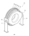
第一実施形態は、ガントリ20において、リング40とリングフレーム50とを、円筒型回転フレーム30の外側の前後端部(回転軸方向に沿った端部のうち、被検体が挿入される方を前端部とする)に2列配置した実施形態である。以下、図2から図5に基づいて、第一実施形態にかかるX線CT装置10のガントリ20の概略構成について説明する。図2は、ガントリ20の正面図、図3は、ガントリ20の前方斜視図、図4は、ガントリ20の後方斜視図、図5(a)は、ガントリ20内の円筒型の回転フレーム30の断面形状を説明するための模式図、図5(b)は、図5(a)の一点鎖線内の部分拡大図であって、ガントリ20外側に備えられたリング40及びリングフレーム50の断面形状を説明するための部分拡大図である。
<First embodiment>
In the first embodiment, in the
ガントリ20は、スタンド21と、軸受け22、主フレーム23、円筒型回転フレーム30、リング40、及びリングフレーム50とを備える。
The
主フレーム23は、軸受け22を介してスタンド21に前後方向にティルト動作可能に支持されている。
The
主フレーム23の内側には、内側から外側に向かって順に、円筒型回転フレーム30と、リング40と、リングフレーム50とが備えられる。円筒型回転フレーム30は、X線管装置31、X線検出器32、および図示していないが、高電圧発生機器、制御機器等のCT検査に必要な機器を搭載し、これらの機器を開口部33に搬送された寝台3上に載置された被検体2の周囲に回転させるものである。円筒型回転フレーム30は、図示していないがベアリングにより、主フレーム23に紙面垂直方向を中心軸として回転可能に支持されている。
Inside the
また、円筒型回転フレーム30の外側には、円筒型回転フレーム30の外周を包み込む様に、且つ、正常な回転動作では接触しない限界的な空間距離d(例えば、円筒型回転フレーム30の熱伸び量や、遠心力による変形量)だけ離した位置に、リング40が配置される。図5(a)、図5(b)に示すように、リング40の更に外側には、リングフレーム50が配置され、リング40とリングフレーム50とは、スベリ面を介して接し、リング40はリングフレーム50に対し、回転可能に支持されている。リングフレーム50は、主フレーム23に固定支持される。
Further, the outer space of the cylindrical
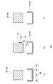
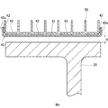
続いて、リング40とリングフレーム50の構造を図6、図7を用いて説明する。図6は、リング40及びリングフレーム50の分解図、図7は、図2おけるA−A’断面図である。
Next, the structure of the
図6(a)に示すように、リング40は、リング本体41と滑り材42とから成り、滑り材42はリング本体41に固定されている。滑り材42の材質は、例えば四フッ化エチレン樹脂であり、一般的に滑り軸受けに使用されているものを用いてもよい。また、滑り材は、図6(b)に示すように、リングフレーム50に固定、すなわち、リングフレーム50を、リングフレーム51本体とその本体に固定した滑り材52とにより構成してもよい。また、図6(c)は、リング本体41の材質を例えば砲金や真鍮とした場合であり、この場合は、リングフレーム本体51との接触面にグリース等の潤滑材が塗布されている。上記のごとく、リング40は、滑り材42又は52の外表面からなるすべり面、又は潤滑材を塗布された接触面により構成したすべり面を介してリングフレーム50に回転自在に取り付けられている。
As shown in FIG. 6A, the
次に図7に基づいて、円筒型回転フレーム30、リング40、及びリングフレーム50の取り付け構造について説明する。
Next, a mounting structure for the cylindrical
リング40は、円筒型回転フレーム30の外周面30aから空間距離dだけを離して備えられる。リング40は、外側に凸の外側鍔部40aがついているので、リング40は脱輪することなくリングフレーム50の内周面に沿って回転可能である。
The
次に本実施形態の動作について説明する。円筒型回転フレーム30が、前述した通り鋳物製作不良等の欠陥により所定の強度が確保されていない場合、回転による遠心力に耐えることが出来ず円筒型回転フレーム30が割れて外側に広がることがある。この場合、リング40に押さえつけられ円筒型回転フレーム30の飛散が防止されるとともに、変形後の円筒型回転フレーム30がリング40に遠心力により押し付けられ、円筒型回転フレーム30とリング40とが一体となってリングフレーム50の内周面をすべる。このとき、リング40とリングフレーム50との間には、遠心力にその摩擦係数を乗じた摩擦力が発生する為、回転動作に制動をかけることが出来る。
Next, the operation of this embodiment will be described. If the cylindrical
第一実施形態では、リング40とリングフレーム50とを、円筒型回転フレーム30の外側の前後端部(回転軸方向に沿った端部のうち、被検体2が挿入される方を前端部とする)に2列配置したが、リング40を、円筒型回転フレーム30においてX線管装置31の荷重が加わる点により近い端部にのみ備えるようにしてもよい。例えば、第一実施形態では、X線管装置31が円筒型回転フレームの全幅の中央よりも前側に位置しているので、前端部にのみリング40を備えるように構成してもよい。そして、さらにリング40を追加する場合には、後端部に限らず円筒型回転フレーム30の外周面に対向する任意の位置に、リング40の幅に応じて任意の本数を備えるように構成してもよい。
In the first embodiment, the
<その他の実施形態>
次に図8に基づいて、第二実施形態について説明する。図8は第二実施形態にかかるリング40及びリングフレーム50の断面図である。第二実施形態では、リング40が円筒形回転フレーム30の外周面の全幅(回転動作の回転軸方向に沿った前端部から後端部までの幅)を覆うように備えられる。また、リング40の前端部及び後端部には、外側に向かって凸形状の外向き鍔部40aを備え、外向き鍔部40aがリングフレーム50の回転軸方向の動きを規制するように構成される。リング本体41におけるリングフレーム50と対向する面、及びリング本体41における外向き鍔部40aのリングフレーム50と対向する面には、滑り材42が備えられる。
<Other embodiments>
Next, a second embodiment will be described based on FIG. FIG. 8 is a cross-sectional view of the
続いて、図9に基づいて、第三実施形態について説明する。図9は第三実施形態にかかるリング40及びリングフレーム50の断面図である。第三実施形態では、リング40が円筒形回転フレーム30の外周面の全幅(回転動作の回転軸方向に沿った前端部から後端部までの幅)を覆うように備えられる。また、リング40の前端部及び後端部には、内側に向かって凸形状の内向き鍔部40bを備え、内向き鍔部40bが円筒形回転フレーム30の回転軸方向の動きを規制するように構成される。
Next, a third embodiment will be described based on FIG. FIG. 9 is a cross-sectional view of the
第二実施形態は、第三実施形態と比較すると、リング40とリングフレーム50との接触面積をより増やすことができるため、破損時に円筒形回転フレーム30の回転動作により強く制動をかけることができる。また、滑り材としてグリースを使用した場合に、外向き鍔部40aによりグリース漏れを抑止することができる。
Compared with the third embodiment, the second embodiment can further increase the contact area between the
また、第三実施形態は、第二実施形態と比較して、内向き鍔部40bにより、円筒型フレーム30をより広く覆うことができるため、部品の飛散が生じた場合にもより飛散範囲を狭めることができる。一方、第二実施形態では外向き鍔部40aにおけるリングフレーム50の対向面に備えた滑り材42を備えたが、それに相当する滑り材42が不要となる。
In addition, since the third embodiment can cover the
上記実施形態では、滑り材をリング40又はリングフレーム50のそれぞれの対向面に部分的に備えたが、リング40又はリングフレーム50のそれぞれの対向面の全面に備えてもよい。
In the above embodiment, the sliding material is partially provided on the opposing surfaces of the
1:ガントリ筐体、2:被検体、3:寝台、4:画像処理装置、5:表示装置、6:操作装置、10:X線CT装置、20:ガントリ、21:スタンド、22:軸受け、23:主フレーム、30:円筒型回転フレーム、30a:外周面、31:X線管装置、32:X線検出器、33:開口部、40:リング、40a:外向き鍔部、40b:内向き鍔部、41:リング本体、42:滑り材、50:リングフレーム、51:リングフレーム本体、52:滑り材。 1: gantry housing, 2: subject, 3: bed, 4: image processing device, 5: display device, 6: operation device, 10: X-ray CT device, 20: gantry, 21: stand, 22: bearing, 23: main frame, 30: cylindrical rotary frame, 30a: outer peripheral surface, 31: X-ray tube device, 32: X-ray detector, 33: opening, 40: ring, 40a: outward flange, 40b: inside Orientation collar part, 41: ring main body, 42: sliding material, 50: ring frame, 51: ring frame main body, 52: sliding material.
Claims (3)
前記X線を検出して透過X線信号を出力するX線検出器と、
前記X線管装置及び前記X線検出器を対向させて搭載し、被検体の周囲を回転するガントリと、
前記透過X線信号に基づいて再構成演算を行い、前記被検体の再構成画像を生成する画像再構成部と、
を備えたX線CT装置であって、
前記ガントリは、
開口部を有する円筒型の回転フレームであって、前記開口部に面する内周面に前記X線管装置及び前記X線検出器を搭載して回転する回転フレームと、
前記回転フレームの回転動作と連動することなく、前記回転フレームを回転自在に支持する支持体と、
前記回転フレームの外周面の少なくとも一部幅を覆うリングであって、前記回転フレームの正常な回転動作では接触せず、かつ、前記回転動作中に前記回転フレームの変形を伴う異常が生じた場合に、前記変形後の回転フレームが接触する程度の空間距離を前記回転フレームの外周面との間に空けて備えられたリングと、
前記支持体に固定され、前記リングの外周面を覆うリングフレームであって、前記リングを、すべり面を介して回転自在に支持するリングフレームと、
を備えることを特徴とするX線CT装置。 An X-ray tube device for generating X-rays;
An X-ray detector that detects the X-ray and outputs a transmitted X-ray signal;
A gantry that mounts the X-ray tube device and the X-ray detector facing each other, and rotates around the subject;
An image reconstruction unit that performs a reconstruction operation based on the transmitted X-ray signal and generates a reconstructed image of the subject;
An X-ray CT apparatus comprising:
The gantry is
A cylindrical rotating frame having an opening, wherein the rotating frame is rotated by mounting the X-ray tube device and the X-ray detector on an inner peripheral surface facing the opening;
A support that rotatably supports the rotating frame without interlocking with the rotating operation of the rotating frame;
A ring that covers at least a part of the width of the outer peripheral surface of the rotating frame, and does not come into contact with the rotating frame in a normal rotating operation, and an abnormality accompanied by deformation of the rotating frame occurs during the rotating operation. In addition, a ring provided with a space distance between the outer peripheral surface of the rotating frame and a space distance to which the rotating frame after the deformation comes into contact,
A ring frame fixed to the support and covering an outer peripheral surface of the ring, the ring frame supporting the ring rotatably via a sliding surface;
An X-ray CT apparatus comprising:
前記X線CT装置は、前記回転動作の回転軸方向に沿った前記回転フレームの両端部のうち、前記回転フレームに前記X線管装置の荷重が加わる点を基準とし、この点により近い端部に前記リングを備える、
ことを特徴とする請求項1に記載のX線CT装置。 The ring is a ring that covers a partial width of the outer peripheral surface of the rotating frame,
The X-ray CT apparatus is based on a point at which the load of the X-ray tube apparatus is applied to the rotating frame among both ends of the rotating frame along the rotation axis direction of the rotating operation, and an end closer to this point Provided with the ring,
The X-ray CT apparatus according to claim 1.
ことを特徴とする請求項1に記載のX線CT装置。 The ring is a ring that covers the entire width of the outer peripheral surface.
The X-ray CT apparatus according to claim 1.
Priority Applications (1)
| Application Number | Priority Date | Filing Date | Title |
|---|---|---|---|
| JP2009050955A JP5276478B2 (en) | 2009-03-04 | 2009-03-04 | X-ray CT system |
Applications Claiming Priority (1)
| Application Number | Priority Date | Filing Date | Title |
|---|---|---|---|
| JP2009050955A JP5276478B2 (en) | 2009-03-04 | 2009-03-04 | X-ray CT system |
Publications (3)
| Publication Number | Publication Date |
|---|---|
| JP2010201026A JP2010201026A (en) | 2010-09-16 |
| JP2010201026A5 JP2010201026A5 (en) | 2012-04-05 |
| JP5276478B2 true JP5276478B2 (en) | 2013-08-28 |
Family
ID=42963135
Family Applications (1)
| Application Number | Title | Priority Date | Filing Date |
|---|---|---|---|
| JP2009050955A Expired - Fee Related JP5276478B2 (en) | 2009-03-04 | 2009-03-04 | X-ray CT system |
Country Status (1)
| Country | Link |
|---|---|
| JP (1) | JP5276478B2 (en) |
Families Citing this family (3)
| Publication number | Priority date | Publication date | Assignee | Title |
|---|---|---|---|---|
| WO2013093691A1 (en) * | 2011-12-20 | 2013-06-27 | Koninklijke Philips Electronics N.V. | Imaging system gantry |
| US9538963B2 (en) * | 2013-03-15 | 2017-01-10 | Aktiebolaget Skf | Diagnostic scanning apparatus |
| CN107970039B (en) * | 2017-12-18 | 2020-11-27 | 赵汝莲 | Movable radiology department CT device |
Family Cites Families (6)
| Publication number | Priority date | Publication date | Assignee | Title |
|---|---|---|---|---|
| US5473657A (en) * | 1994-02-08 | 1995-12-05 | Analogic Corporation | X-ray tomographic scanning system |
| JPH0947448A (en) * | 1995-08-08 | 1997-02-18 | Toshiba Corp | X-ray ct scanner |
| DE19629931C2 (en) * | 1996-07-24 | 2000-04-06 | Siemens Ag | X-ray computer tomograph |
| JP4406101B2 (en) * | 1998-10-16 | 2010-01-27 | 株式会社東芝 | X-ray CT system |
| JP2001137225A (en) * | 1999-11-11 | 2001-05-22 | Hitachi Medical Corp | X-ray ct apparatus |
| JP4751663B2 (en) * | 2005-08-05 | 2011-08-17 | 株式会社日立メディコ | X-ray CT system |
-
2009
- 2009-03-04 JP JP2009050955A patent/JP5276478B2/en not_active Expired - Fee Related
Also Published As
| Publication number | Publication date |
|---|---|
| JP2010201026A (en) | 2010-09-16 |
Similar Documents
| Publication | Publication Date | Title |
|---|---|---|
| JP5276478B2 (en) | X-ray CT system | |
| KR100198516B1 (en) | X-ray tomographic scanning system | |
| US7508904B2 (en) | X-ray CT apparatus | |
| WO2010119850A1 (en) | X-ray ct device | |
| JPH1057368A (en) | Computed tomograph | |
| US5703921A (en) | X-ray computed tomography apparatus | |
| JP2013524969A5 (en) | ||
| JP5904731B2 (en) | X-ray CT system mount | |
| EP2211720B1 (en) | High speed rotating gantry | |
| CN105408732A (en) | Testing device for thin-walled large bearing | |
| JP2015184080A (en) | Test device of thin-thickness large-sized bearing | |
| CN108836371B (en) | Orbital clutch and brake assembly for a C-arm of an imaging system | |
| EP3225168A1 (en) | Gantry system with support wheels | |
| JP5872574B2 (en) | Rolling disc hydrodynamic bearing system | |
| JP2013524965A5 (en) | ||
| JP2007325919A (en) | X-ray ct apparatus | |
| US20160058398A1 (en) | Rotor for a gantry of a computed tomograpy apparatus | |
| JP2004097828A (en) | C-arm x-ray apparatus with mechanically adjustable brake | |
| JP4761898B2 (en) | X-ray computed tomography system | |
| US8021044B2 (en) | X-ray tomography apparatus | |
| JPH0415205Y2 (en) | ||
| JP4735827B2 (en) | X-ray fluoroscopy system | |
| JP2006132670A (en) | Super-thin roller bearing | |
| WO2021199873A1 (en) | Roller bearing | |
| JP2011030587A (en) | X-ray ct apparatus and noncontact power transmission means |
Legal Events
| Date | Code | Title | Description |
|---|---|---|---|
| A521 | Request for written amendment filed |
Free format text: JAPANESE INTERMEDIATE CODE: A523 Effective date: 20120216 |
|
| A621 | Written request for application examination |
Free format text: JAPANESE INTERMEDIATE CODE: A621 Effective date: 20120216 |
|
| TRDD | Decision of grant or rejection written | ||
| A01 | Written decision to grant a patent or to grant a registration (utility model) |
Free format text: JAPANESE INTERMEDIATE CODE: A01 Effective date: 20130423 |
|
| A977 | Report on retrieval |
Free format text: JAPANESE INTERMEDIATE CODE: A971007 Effective date: 20130424 |
|
| A61 | First payment of annual fees (during grant procedure) |
Free format text: JAPANESE INTERMEDIATE CODE: A61 Effective date: 20130517 |
|
| R150 | Certificate of patent or registration of utility model |
Free format text: JAPANESE INTERMEDIATE CODE: R150 Ref document number: 5276478 Country of ref document: JP Free format text: JAPANESE INTERMEDIATE CODE: R150 |
|
| S111 | Request for change of ownership or part of ownership |
Free format text: JAPANESE INTERMEDIATE CODE: R313111 |
|
| S533 | Written request for registration of change of name |
Free format text: JAPANESE INTERMEDIATE CODE: R313533 |
|
| R350 | Written notification of registration of transfer |
Free format text: JAPANESE INTERMEDIATE CODE: R350 |
|
| LAPS | Cancellation because of no payment of annual fees |