JP5275796B2 - Composite self-adhesive web material - Google Patents
Composite self-adhesive web material Download PDFInfo
- Publication number
- JP5275796B2 JP5275796B2 JP2008524002A JP2008524002A JP5275796B2 JP 5275796 B2 JP5275796 B2 JP 5275796B2 JP 2008524002 A JP2008524002 A JP 2008524002A JP 2008524002 A JP2008524002 A JP 2008524002A JP 5275796 B2 JP5275796 B2 JP 5275796B2
- Authority
- JP
- Japan
- Prior art keywords
- web material
- web
- implantable article
- stretched
- polymer component
- Prior art date
- Legal status (The legal status is an assumption and is not a legal conclusion. Google has not performed a legal analysis and makes no representation as to the accuracy of the status listed.)
- Active
Links
Images


Classifications
-
- A—HUMAN NECESSITIES
- A61—MEDICAL OR VETERINARY SCIENCE; HYGIENE
- A61L—METHODS OR APPARATUS FOR STERILISING MATERIALS OR OBJECTS IN GENERAL; DISINFECTION, STERILISATION OR DEODORISATION OF AIR; CHEMICAL ASPECTS OF BANDAGES, DRESSINGS, ABSORBENT PADS OR SURGICAL ARTICLES; MATERIALS FOR BANDAGES, DRESSINGS, ABSORBENT PADS OR SURGICAL ARTICLES
- A61L31/00—Materials for other surgical articles, e.g. stents, stent-grafts, shunts, surgical drapes, guide wires, materials for adhesion prevention, occluding devices, surgical gloves, tissue fixation devices
- A61L31/14—Materials characterised by their function or physical properties, e.g. injectable or lubricating compositions, shape-memory materials, surface modified materials
- A61L31/148—Materials at least partially resorbable by the body
-
- A—HUMAN NECESSITIES
- A61—MEDICAL OR VETERINARY SCIENCE; HYGIENE
- A61B—DIAGNOSIS; SURGERY; IDENTIFICATION
- A61B17/00—Surgical instruments, devices or methods, e.g. tourniquets
- A61B17/068—Surgical staplers, e.g. containing multiple staples or clamps
- A61B17/072—Surgical staplers, e.g. containing multiple staples or clamps for applying a row of staples in a single action, e.g. the staples being applied simultaneously
- A61B17/07292—Reinforcements for staple line, e.g. pledgets
-
- A—HUMAN NECESSITIES
- A61—MEDICAL OR VETERINARY SCIENCE; HYGIENE
- A61L—METHODS OR APPARATUS FOR STERILISING MATERIALS OR OBJECTS IN GENERAL; DISINFECTION, STERILISATION OR DEODORISATION OF AIR; CHEMICAL ASPECTS OF BANDAGES, DRESSINGS, ABSORBENT PADS OR SURGICAL ARTICLES; MATERIALS FOR BANDAGES, DRESSINGS, ABSORBENT PADS OR SURGICAL ARTICLES
- A61L31/00—Materials for other surgical articles, e.g. stents, stent-grafts, shunts, surgical drapes, guide wires, materials for adhesion prevention, occluding devices, surgical gloves, tissue fixation devices
- A61L31/14—Materials characterised by their function or physical properties, e.g. injectable or lubricating compositions, shape-memory materials, surface modified materials
- A61L31/146—Porous materials, e.g. foams or sponges
-
- Y—GENERAL TAGGING OF NEW TECHNOLOGICAL DEVELOPMENTS; GENERAL TAGGING OF CROSS-SECTIONAL TECHNOLOGIES SPANNING OVER SEVERAL SECTIONS OF THE IPC; TECHNICAL SUBJECTS COVERED BY FORMER USPC CROSS-REFERENCE ART COLLECTIONS [XRACs] AND DIGESTS
- Y10—TECHNICAL SUBJECTS COVERED BY FORMER USPC
- Y10T—TECHNICAL SUBJECTS COVERED BY FORMER US CLASSIFICATION
- Y10T428/00—Stock material or miscellaneous articles
- Y10T428/13—Hollow or container type article [e.g., tube, vase, etc.]
- Y10T428/131—Glass, ceramic, or sintered, fused, fired, or calcined metal oxide or metal carbide containing [e.g., porcelain, brick, cement, etc.]
- Y10T428/1317—Multilayer [continuous layer]
-
- Y—GENERAL TAGGING OF NEW TECHNOLOGICAL DEVELOPMENTS; GENERAL TAGGING OF CROSS-SECTIONAL TECHNOLOGIES SPANNING OVER SEVERAL SECTIONS OF THE IPC; TECHNICAL SUBJECTS COVERED BY FORMER USPC CROSS-REFERENCE ART COLLECTIONS [XRACs] AND DIGESTS
- Y10—TECHNICAL SUBJECTS COVERED BY FORMER USPC
- Y10T—TECHNICAL SUBJECTS COVERED BY FORMER US CLASSIFICATION
- Y10T428/00—Stock material or miscellaneous articles
- Y10T428/13—Hollow or container type article [e.g., tube, vase, etc.]
- Y10T428/1352—Polymer or resin containing [i.e., natural or synthetic]
- Y10T428/1372—Randomly noninterengaged or randomly contacting fibers, filaments, particles, or flakes
-
- Y—GENERAL TAGGING OF NEW TECHNOLOGICAL DEVELOPMENTS; GENERAL TAGGING OF CROSS-SECTIONAL TECHNOLOGIES SPANNING OVER SEVERAL SECTIONS OF THE IPC; TECHNICAL SUBJECTS COVERED BY FORMER USPC CROSS-REFERENCE ART COLLECTIONS [XRACs] AND DIGESTS
- Y10—TECHNICAL SUBJECTS COVERED BY FORMER USPC
- Y10T—TECHNICAL SUBJECTS COVERED BY FORMER US CLASSIFICATION
- Y10T428/00—Stock material or miscellaneous articles
- Y10T428/13—Hollow or container type article [e.g., tube, vase, etc.]
- Y10T428/1352—Polymer or resin containing [i.e., natural or synthetic]
- Y10T428/1376—Foam or porous material containing
-
- Y—GENERAL TAGGING OF NEW TECHNOLOGICAL DEVELOPMENTS; GENERAL TAGGING OF CROSS-SECTIONAL TECHNOLOGIES SPANNING OVER SEVERAL SECTIONS OF THE IPC; TECHNICAL SUBJECTS COVERED BY FORMER USPC CROSS-REFERENCE ART COLLECTIONS [XRACs] AND DIGESTS
- Y10—TECHNICAL SUBJECTS COVERED BY FORMER USPC
- Y10T—TECHNICAL SUBJECTS COVERED BY FORMER US CLASSIFICATION
- Y10T442/00—Fabric [woven, knitted, or nonwoven textile or cloth, etc.]
- Y10T442/20—Coated or impregnated woven, knit, or nonwoven fabric which is not [a] associated with another preformed layer or fiber layer or, [b] with respect to woven and knit, characterized, respectively, by a particular or differential weave or knit, wherein the coating or impregnation is neither a foamed material nor a free metal or alloy layer
- Y10T442/2525—Coating or impregnation functions biologically [e.g., insect repellent, antiseptic, insecticide, bactericide, etc.]
-
- Y—GENERAL TAGGING OF NEW TECHNOLOGICAL DEVELOPMENTS; GENERAL TAGGING OF CROSS-SECTIONAL TECHNOLOGIES SPANNING OVER SEVERAL SECTIONS OF THE IPC; TECHNICAL SUBJECTS COVERED BY FORMER USPC CROSS-REFERENCE ART COLLECTIONS [XRACs] AND DIGESTS
- Y10—TECHNICAL SUBJECTS COVERED BY FORMER USPC
- Y10T—TECHNICAL SUBJECTS COVERED BY FORMER US CLASSIFICATION
- Y10T442/00—Fabric [woven, knitted, or nonwoven textile or cloth, etc.]
- Y10T442/60—Nonwoven fabric [i.e., nonwoven strand or fiber material]
- Y10T442/681—Spun-bonded nonwoven fabric
Description
本発明は、移植可能な医療用材料及びデバイスに関する。より特定的には、本発明は、高度の多孔性をもつ不織自己密着フィラメント状ウェブの形をした生体吸収性重合体材料で作られた移植可能な医療用材料及びデバイスに向けられている。 The present invention relates to implantable medical materials and devices. More specifically, the present invention is directed to implantable medical materials and devices made of bioabsorbable polymeric materials in the form of highly porous nonwoven self-adhering filamentary webs. .
医療利用分野で使用するためのさまざまな生体吸収性重合体化合物が開発されてきている。これらの化合物から作られた材料は、被移植者の体内に永続的に残留しない移植可能なデバイスを構築するために使用可能である。生体吸収性材料は、被移植者に生来備わっている生理学的プロセスにより被移植者の体から除去される。これらのプロセスには、生体吸収性化合物の全て又は一部分の単なる溶解、生体吸収性化合物内の不安定な化学結合の加水分解、酵素作用及び/又は材料の表面浸食が含まれ得る。これらのプロセスの分解生成物は通常、肺、肝臓及び/又は腎臓の作用を通して、被移植者から除去される。文献中、「生体再吸収性」「再吸収性」「生体吸収性」及び「生分解性」というのは、互換的に使用されることの多い用語であることが認識されている。本書では「生体吸収性」が好適な用語である。 Various bioabsorbable polymer compounds have been developed for use in the medical field. Materials made from these compounds can be used to construct implantable devices that do not persist permanently in the recipient's body. The bioabsorbable material is removed from the recipient's body by the physiological processes inherent in the recipient. These processes may include simple dissolution of all or part of the bioabsorbable compound, hydrolysis of labile chemical bonds within the bioabsorbable compound, enzymatic action and / or surface erosion of the material. The degradation products of these processes are usually removed from the recipient through the action of the lungs, liver and / or kidneys. In the literature, it is recognized that “bioresorbable”, “resorbable”, “bioresorbable” and “biodegradable” are terms that are often used interchangeably. In this document, “bioresorbability” is the preferred term.
生体吸収性重合体化合物が、創傷の縫合及び復元という利用分野で何十年にもわたり使用されてきた。縫合糸が最も顕著な例である。成形品、フィルム、フォーム、積層品、製織又は不織材料も同様に、生体吸収性重合体化合物で生産されてきた。生物学的に活性な組成物が、これらの生体吸収性化合物のいくつかと放出可能な形で組合わされてきた。 Bioabsorbable polymer compounds have been used for decades in the field of wound suturing and restoration. Sutures are the most prominent example. Molded articles, films, foams, laminates, woven or non-woven materials have likewise been produced with bioabsorbable polymer compounds. Biologically active compositions have been releasably combined with some of these bioabsorbable compounds.
Hayesに交付された米国特許第6,165,217号(U.S. Patent No. 6,165,217)は、不織自己密着ウェブの形をした生体吸収性材料を開示している(本書の図1及び1A)。自己密着不織ウェブ材料は、単数又は複数の半結晶性又は非晶質重合体構成成分と線状ブロック共重合体として共有結合された又はこの構成成分と配合された少なくとも1つの半結晶性重合体構成成分で作られた連続フィラメントの紡糸ウェブである。 US Pat. No. 6,165,217 (U.S. Patent No. 6,165,217) issued to Hayes discloses a bioabsorbable material in the form of a non-woven self-adhering web (FIGS. 1 and 1A of this document). The self-adhering nonwoven web material comprises at least one semi-crystalline weight that is covalently bonded or blended with the one or more semi-crystalline or amorphous polymer components as a linear block copolymer. A continuous filament spun web made of coalesced components.
連続フィラメントは、出現するフィラメントに粘着性を提供し、フィラメントが収集表面上で凝集性ランダムパイル又はウェブ内に収集されるにつれて硬いフィラメントとして自己密着することができるようにする紡糸条件を選定することによって生産可能である。この紡糸フィラメントは、自己密着フィラメントの多孔性ウェブの形で収集されるにつれて共に混り合わされる。自己密着フィラメントは、該ウェブ内で互いに多数の接触点を有する。補足的接着剤、結合剤、接着性付加物(例えば溶媒、粘着付与剤樹脂、柔軟材)の必然的な添加又は押出し成形後の溶融加工の必要性無く、自己密着フィラメントは接触点で接着する。好ましい実施形態のポリグリコリド:トリメチレンカーボナート(PGA:TMC)不織ウェブの自己密着フィラメントの直径は、20ミクロン〜50ミクロンの間である。Hayesに従うと、これらの自己密着不織ウェブは、多孔性百分率が約40〜80の間の範囲内にあることを表わす体積密度(見かけ密度としても報告されているもの)を有する。潜在的に半結晶性であるウェブが、熱力学的に不安定(準安定)で均質(ミクロ相が無秩序)な、実質的に相混和性の、結晶度が制限された非晶質状態にある場合、このウェブは展性をもち、所望の形状に即時適合させ成形することができる。このとき造形された形状は、より秩序立った熱力学的に安定した、少なくとも部分的に相非混和の半結晶性状態へのその転換全体を通して保つことができる。長時間の非晶質(すなわち混和性の無秩序状態)条件から秩序ある半結晶性状態へのこの不可逆的な(成形されたウェブ構造の完全な再溶融及び再成形に達していない)転換は、標準的に、溶融温度と秩序−無秩序遷移温度(Todt)すなわちそれ以上になると無秩序から秩序への遷移が進行しうる温度との間に存在するゴム状態において存在する鎖可動性によって提供される。代替的には、溶媒、潤滑剤又は可塑化剤を、熱と組合せて、又は組合せずに、成分重合体鎖の鎖可動性及びより秩序ある条件への再配置を容易にするために使用可能である。自己密着フィラメントの化学組成は、結果として得られるウェブが移植可能で生体吸収性をもつような形で選択可能である。 Choosing spinning conditions that allow continuous filaments to stick to emerging filaments and allow them to self-adhere as hard filaments as they are collected in a coherent random pile or web on the collection surface Can be produced by. The spun filaments are blended together as they are collected in the form of a porous web of self-adhering filaments. Self-adhering filaments have multiple contact points with each other within the web. Self-adhering filaments adhere at the point of contact without the inevitable addition of supplementary adhesives, binders, adhesive adducts (eg solvents, tackifier resins, softeners) or the need for melt processing after extrusion . A preferred embodiment of the polyglycolide: trimethylene carbonate (PGA: TMC) nonwoven web has a self-adhering filament diameter between 20 microns and 50 microns. According to Hayes, these self-adhering nonwoven webs have a volume density (also reported as an apparent density) representing a porosity percentage in the range of between about 40-80. A potentially semi-crystalline web is in a thermodynamically unstable (metastable) and homogeneous (microphase disordered), substantially phase-miscible, crystallinity limited, amorphous state In some cases, the web is malleable and can be molded and immediately adapted to the desired shape. The shaped shape can then be maintained throughout its transformation to a more ordered thermodynamically stable and at least partially phase-immiscible semicrystalline state. This irreversible (not reaching full remelting and reshaping of the shaped web structure) from prolonged amorphous (ie miscible disordered state) conditions to an ordered semicrystalline state is Typically provided by the chain mobility that exists in the rubbery state that exists between the melting temperature and the order-disorder transition temperature (T odt ), or higher, at which the transition from disorder to order can proceed. . Alternatively, solvents, lubricants or plasticizers can be used to facilitate chain mobility of component polymer chains and rearrangement to more ordered conditions, with or without heat. It is. The chemical composition of the self-adhering filament can be selected such that the resulting web is implantable and bioabsorbable.
Hayesは、繊維の被着密度及び何らかの後続する圧縮に基づいて可変的な度合の多孔性を有するものとして、自己密着不織ウェブ材料を記述している。Hayesは又、展性が不安定な非晶質条件にある平面が有している、後続する結晶化により保持され得る形状をもつ事実上無制限の数多くの成形品へと造形される能力についても記述している。しかしながら、Hayesは、アニーリングに先立ちウェブの多孔率を増大させるための付加的なストレッチ加工用の前躯体ウェブ材料として役立ち得る自己密着フィラメントの未硬化のウェブについては記していない。さらにHayesは、20ミクロン未満の横断直径をもつ連続フィラメントの有意な集団を有する自己密着不織ウェブ材料も教示していない。本発明に従った前躯体ウェブ材料の付加的加工が無い状態で、Hayesの自己密着不織ウェブ材料が、0.050超の複屈析値を提供するのに充分なウェブの自己密着フィラメント内の増大した分子配向を有することはないと思われる。 Hayes describes self-adhering nonwoven web materials as having a variable degree of porosity based on fiber deposition density and any subsequent compression. Hayes also has the ability to be shaped into a virtually unlimited number of moldings that have a shape that can be retained by subsequent crystallization, possessing a plane that is in an amorphous condition with unstable malleability. It is described. However, Hayes does not describe an uncured web of self-bonding filaments that can serve as a precursor web material for additional stretch processing to increase the porosity of the web prior to annealing. Furthermore, Hayes does not teach self-adhering nonwoven web materials having a significant population of continuous filaments with a cross diameter of less than 20 microns. In the absence of additional processing of the precursor web material according to the present invention, Hayes' self-adhering nonwoven web material is sufficient in the self-adhering filaments of the web to provide double segregation values greater than 0.050. It does not appear to have increased molecular orientation.
高い多孔率と小さなフィラメント直径をもつ不織自己密着ウェブ材料は、単数又は複数の方向において比例的に増大した機械的強度を有することになる。機械的強度の増大にも関わらず、このような高多孔率不織自己密着ウェブ材料は、Hauesに従って作られたウェブ材料よりもさらに大きなロフト、しなやかさ、ドレープ性、形状整合性及び組織コンプライアンスを提供すると思われる。 Nonwoven self-cohered web materials with high porosity and small filament diameter will have a proportionally increased mechanical strength in one or more directions. Despite the increase in mechanical strength, such high porosity non-woven self-adhesive web materials offer even greater loft, suppleness, drapeability, shape consistency and tissue compliance than web materials made according to Haues. It seems to provide.
移植可能でない利用分野においては、移植可能なデバイス及び材料を送達器具に放出可能な形で付着させるために高度の多孔性をもつ不織自己密着ウェブを使用することができるだろう。配向されたフィラメントがその内部で移動することのできる内部空隙体積の増大と配向されたフィラメントの集合を組合せることで、このような材料に或る程度の弾性又は復元力が浸透されることになるだろう。 In non-implantable applications, non-woven self-adhering webs with a high degree of porosity could be used to releasably attach implantable devices and materials to delivery devices. Combining an increase in the internal void volume within which the oriented filaments can move and the collection of oriented filaments will allow some elasticity or restoring force to penetrate into such materials. It will be.
このようなウェブ材料におけるこれらの及びその他の改善に加えて、より多孔性の高い生体吸収性ウェブ材料は、ウェブとその他の構成要素を組合せる機会を提供すると思われる。該構成要素はフィラメントの表面上に配置され得るだろう。該構成要素を、空隙空間又は気孔内部、フィラメントの間に配置することもできると思われる。該構成要素は生体吸収性でも非生体吸収性でもあり得るだろう。該構成要素自体、放出可能な形で有用な物質を含有することができよう。 In addition to these and other improvements in such web materials, a more porous bioabsorbable web material would provide an opportunity to combine the web with other components. The component could be placed on the surface of the filament. It would also be possible to place the component inside the void space or pores, between the filaments. The component could be bioabsorbable or non-bioabsorbable. The component itself could contain useful substances in a releasable form.
従って、増大した機械的強度、ロフト、しなやかさ、ドレープ性、形状整合性及び組織コンプライアンスが伴う、高度の多孔性を有する合成の生体吸収性不織自己密着重合体ウェブ材料に対するニーズが存在する。 Accordingly, there is a need for a synthetic bioabsorbable nonwoven self-adhering polymeric web material having a high degree of porosity with increased mechanical strength, loft, suppleness, drapeability, shape conformability and tissue compliance.
本発明は、高度の多孔性をもつ合成の生体吸収性不織自己密着重合体ウェブ材料に向けられている。高多孔性ウェブ材料は、機械的に強く、高度のロフト、しなやかさ、ドレープ性、形状整合性及び組織コンプライアンスを有する。一部の実施形態においては、本発明は、弾性特性を示す。該発明は、移植可能な医療用デバイス又は医療デバイスの1構成要素として使用するのに適している。該発明は同様に、出血部位又は動脈瘤形成部位における血栓形成剤として数多くのケースにおいて使用するのにも適している。 The present invention is directed to a synthetic bioabsorbable nonwoven self-adhering polymeric web material having a high degree of porosity. Highly porous web materials are mechanically strong and have a high degree of loft, suppleness, draping, shape matching and tissue compliance. In some embodiments, the present invention exhibits elastic properties. The invention is suitable for use as an implantable medical device or as a component of a medical device. The invention is also suitable for use in many cases as a thrombogenic agent at a bleeding site or aneurysm formation site.
これらの特性は、アニールされていない自己密着前躯体ウェブ材料を限定条件下で特定の速度及び伸長比で少なくとも1方向に伸長又は引抜きすることにより、本発明に付与されている。伸長の後には優先的に、完全又は部分的拘束下での熱硬化及び冷却が行なわれる。 These properties are imparted to the present invention by stretching or drawing an unannealed self-adhering precursor web material in a limited speed and stretch ratio in at least one direction under limited conditions. The stretching is preferentially followed by thermosetting and cooling under full or partial restraint.
自己密着前躯体ウェブ材料は、多数の接触点で互いに付着されたフィラメントである(図1及び1A)。加工中、該フィラメントは、接触点を自己密着させることにより共に固定された状態に保たれている。自己密着フィラメントが伸長されるにつれて、フィラメントは引き伸ばされ、横断直径が小さくなる(図2〜4A及び6〜7)。フィラメントが細くなるにつれて、フィラメント間に増大した空隙空間が形成される(表12)。伸長状態の構造はこのとき、完全又は部分的な拘束下で「硬化」又は「アニール」されて少なくとも部分的な相非混和性及び後続する結晶化を誘発する。ウェブ材料の内部に生成されたより細いフィラメント及び増大した空隙空間は、本発明の改善された特徴の多くの原因となっている。 Self-adhering precursor web material is a filament attached to each other at multiple points of contact (FIGS. 1 and 1A). During processing, the filaments are kept fixed together by self-contacting the contact points. As the self-adhering filament is stretched, the filament is stretched and the transverse diameter is reduced (FIGS. 2-4A and 6-7). As the filaments become thinner, increased void spaces are formed between the filaments (Table 12). The stretched structure is then “cured” or “annealed” under full or partial restraint to induce at least partial phase immiscibility and subsequent crystallization. The thinner filaments and increased void space created within the web material are responsible for many of the improved features of the present invention.
多孔性ウェブ材料の空隙空間を定量化するための便利な測定基準は、完成ウェブ材料の多孔性百分率である。多孔性百分率は、完成多孔性ウェブ材料の密度と未加工出発化合物の密度を比較する。本発明の伸長自己密着連続フィラメント不織ウェブ材料は、90パーセント(90%)超の多孔率を有する。本発明においては、ウェブに付与される高い多孔率は、利用可能な多孔率を事実上低減させ得る何らかの充填材又はその他の付加構成成分の内含がない限り、伸長された自己密着ウェブの外側境界の内部に提供された空隙空間として定義づけされる。 A convenient metric for quantifying the void space of the porous web material is the porosity percentage of the finished web material. The porosity percentage compares the density of the finished porous web material with the density of the raw starting compound. The stretched self-adhering continuous filament nonwoven web material of the present invention has a porosity greater than 90 percent (90%). In the present invention, the high porosity imparted to the web is the outside of the stretched self-adhering web, unless there is any filler or other additional component that can effectively reduce the available porosity. It is defined as the void space provided inside the boundary.
本発明は、ウェブ材料の重合体構成成分の上及び/又は内部に配置される付加的な組成物を内含し得る。付加的な組成物をウェブ材料の空隙空間又は気孔の中に入れることも可能である。組成物は、それが放出可能な形で含有する有用な物質を内含することができる。本発明の空隙空間及び表面に配置するための好ましい組成物は、ヒドロゲルベースの材料である。 The present invention may include additional compositions disposed on and / or within the polymer component of the web material. It is also possible to place additional compositions in the void space or pores of the web material. The composition can include useful substances that it contains in a releasable form. A preferred composition for placement in the void spaces and surfaces of the present invention is a hydrogel-based material.
1つの実施形態においては、本発明は、多孔性ウェブを形成するべく混ぜ合わされた溶融成形された連続フィラメントを含む移植可能物品において、前記フィラメントが多数の接触点で互いに自己密着し、前記フィラメントが、少なくとも1つの非晶質重合体構成成分に共有結合した又はこの構成成分と配合された半結晶性重合体構成成分を含んで成り、該フィラメントが、結晶状態にある時に部分的乃至は完全な重合体構成成分相非混和性を有する製品であって、付加的な構成成分が不在である場合に90超の多孔性百分率を有する、移植可能物品である。2つの付加的な実施形態においては、上述の実施形態は、付加的構成成分の不在下で91超又は95超である多孔性百分率を有する。 In one embodiment, the present invention provides an implantable article comprising meltformed continuous filaments blended to form a porous web, wherein the filaments are self-adhering to each other at a number of contact points, Comprising a semi-crystalline polymer component covalently bonded to or blended with at least one amorphous polymer component, wherein the filament is partially or completely when in the crystalline state A product having a polymer component phase immiscibility and an implantable article having a porosity percentage of greater than 90 in the absence of additional components. In two additional embodiments, the above-described embodiments have a porosity percentage that is greater than 91 or greater than 95 in the absence of additional components.
もう1つの実施形態においては、本発明は、多孔性ウェブを形成するべく混ぜ合わされた溶融成形された連続フィラメントを含む移植可能物品において、前記フィラメントが多数の接触点で互いに自己密着し、前記フィラメントが、少なくとも1つの付加的な半結晶性重合体構成成分に共有結合した又はこの構成成分と配合された第1の半結晶性重合体構成成分を含んで成り、該フィラメントが、結晶状態にある時に部分的乃至は完全な重合体構成成分相非混和性を有する製品であって、付加的な構成成分が不在である場合に90超の多孔性百分率を有する、移植可能物品である。 In another embodiment, the present invention provides an implantable article comprising meltformed continuous filaments blended to form a porous web, wherein the filaments are self-adhering to each other at multiple points of contact, wherein the filaments Comprising a first semi-crystalline polymer component covalently bonded to or blended with at least one additional semi-crystalline polymer component, wherein the filament is in a crystalline state An implantable article that sometimes has a partial or complete polymer component phase immiscibility and has a porosity percentage greater than 90 in the absence of additional components.
本発明のこれらの及びその他の特徴並びに該発明自体は、該発明の図面及び詳細記述から、より完全に理解されることになる。 These and other features of the invention, as well as the invention itself, will be more fully understood from the drawings and detailed description of the invention.
本発明は、高度の多孔性をもつ生体吸収性不織自己密着重合体ウェブ材料に向けられている。高度の多孔性は、該発明に多くの所望の特長を付与する。これらの特長には、ロフト、しなやかさ、ドレープ性、形状整合性及び組織コンプライアンスが含まれる。本発明の極めて多孔性のウェブ材料は、移植可能な医療用デバイス又はその構成要素として使用可能である。移植された場合、本発明の極めて多孔性の生体吸収性ウェブ材料は、被移植者に本来備わっている生理的プロセスにより被移植者の体から除去される。 The present invention is directed to a bioabsorbable nonwoven self-adhering polymer web material having a high degree of porosity. The high degree of porosity imparts many desirable features to the invention. These features include loft, suppleness, drapeability, shape consistency and tissue compliance. The highly porous web material of the present invention can be used as an implantable medical device or component thereof. When implanted, the highly porous bioabsorbable web material of the present invention is removed from the recipient's body by the physiological processes inherent to the recipient.
本発明の極めて多孔性のウェブ材料は、アニールされていない不織の自己密着未伸長前躯体ウェブ材料を単数又は複数の方向に伸長させ、その後伸長されたウェブ材料の重合体成分を逐次的又は同時に熱及び/又は適切な溶媒でアニーリングすることにより作られる。前駆体ウェブ材料は、平衡状態に達した時点で系を構成する重合体構成成分の相非混和性のいくつかの証拠を有する半結晶性多成分重合体系から形成された連続フィラメントで作られている。融液からの固化の後最初に自己密着する該前駆体ウェブ材料の能力は、比較的低い結晶化速度の結果であると考えられている。結晶化速度が低いと、該融液の実質的に均質な非晶質非結晶相混合型条件が、固化され急冷されたフィラメント状ウェブの内部で結晶化が制限されている類似の非晶質条件下に維持された連続フィラメントのその他の部分と物理的に接触できる時点まで保存される。連続フィラメントの一部分が前駆体ウェブ材料内の多数の点において互いに接触することから、フィラメントは、付加される接着性結合剤、付加物又は押出し加工後の溶融加工の必要なく、固化された状態で接触点において互いに接着される。このような形で連結された連続又は不連続フィラメントは、「自己密着」しているとみなされる。 The highly porous web material of the present invention extends a non-annealed non-woven self-adhering unstretched precursor web material in one or more directions, and then sequentially or sequentially polymerizes the polymer components of the stretched web material. It is made by simultaneous annealing with heat and / or a suitable solvent. The precursor web material is made of continuous filaments formed from a semi-crystalline multicomponent polymer system with some evidence of the phase immiscibility of the polymer components that make up the system when equilibrium is reached Yes. The ability of the precursor web material to self-adhere first after solidification from the melt is believed to be the result of a relatively low crystallization rate. At low crystallization rates, the substantially homogeneous amorphous amorphous phase mixed type condition of the melt is a similar amorphous material with limited crystallization inside the solidified and quenched filamentous web It is stored until it can be physically contacted with other parts of the continuous filament maintained under conditions. Since a portion of the continuous filament contacts each other at a number of points in the precursor web material, the filament is in a solid state without the need for added adhesive binder, adduct or melt processing after extrusion. Bonded to each other at the contact points. Continuous or discontinuous filaments connected in this manner are considered “self-adhering”.
その非晶質相内部で構成成分が完全に非混和性である状態で存在する配合物及び共重合体系は、それが準安定状態又は平衡状態のいずれにあっても、該系の組成の関数であってFox方程式を用いた場合に実質的に予測可能である温度で発生する単一のTg又はTodtを示すものと予期される。換言すると、完全に非混和性の多相非晶質系は、各々の分離した非混和性相についての単独重合体類似体と相関する全く異なるTgを示すことが予期される。部分混和性系においては、一部の結晶化可能な又はその他の成分は、立体障害又はセグメント内包物といった理由で、既存の非晶質相の内部で混和状態にとどまる。その結果、それぞれのTgは、Fox方程式を用いて解決可能な値である非晶質相内部に存在する成分比を反映する1つの温度に向かって結晶化しないその単独重合体類似体のTgから離れるように移行するものと思われる。 Formulations and copolymer systems in which the components are completely immiscible within the amorphous phase are a function of the composition of the system, whether it is in a metastable or equilibrium state. And is expected to show a single T g or To dt occurring at temperatures that are substantially predictable when using the Fox equation. In other words, a completely immiscible multiphase amorphous system is expected to exhibit a completely different T g that correlates with the homopolymer analog for each separated immiscible phase. In partially miscible systems, some crystallizable or other components remain miscible within the existing amorphous phase because of steric hindrance or segment inclusion. As a result, each T g is the value of that homopolymer analog that does not crystallize toward one temperature that reflects the ratio of components present within the amorphous phase, which is a value that can be solved using the Fox equation. It seems to move away from g .
同様にして、このような部分混和性系の結晶性領域内部の結晶化しない又は非晶質の内包物は、それが充分な濃度で存在する場合、結晶化された単独重合体類似体に予期されるものからの溶融温度の低下を結果としてもたらす希釈効果又は合体効果を生み出すものと予期できる。このような部分混和性系は、観察されたTmの低下を結果としてもたらすと思われ、一方完全相分離された系は単独重合体類似物のTmと類似したTmを保持することになる。 Similarly, a non-crystallized or amorphous inclusion within the crystalline region of such a partially miscible system would be expected for a crystallized homopolymer analog if it is present in sufficient concentration. It can be expected to produce a dilution effect or coalescence effect that results in a lower melting temperature from what is produced. Such partial miscibility system, a reduction in the observed T m appeared to result in, whereas fully phase separated system to hold the T m similar to the T m of the homopolymer analogs Become.
本発明においては、自己密着フィラメントの引き伸ばし及び細線化をひき起こすべく、逐次的か又は同時に前駆体ウェブ材料を単数又は複数の方向に伸長させることができるようにする実質的に均質な非晶質非結晶性準安定相混合条件下で、自己密着前駆体ウェブ材料を懸濁させることができる。前駆体ウェブ材料を伸長させることで、ウェブ材料内の混ざり合ったフィラメントの間の空隙空間が増大する。Hayesは、米国特許第6,165,217号(U.S. Patent No. 6,165,217)の教示に従って作られた完成自己密着ウェブについて、約40〜80%の間の多孔性をもつ材料について記述しているものの、本発明人らは、前駆体ウェブ材料が総材料体積の90パーセント(90%)に至る空隙空間を有することができるということを発見した。この測定基準は、多孔性百分率又は単に「多孔率」として本書で表わされている。多孔率は、例3で記述されている通りに決定される。本発明の完成ウェブ材料は、90パーセント(90%)超の多孔率値を有する(表12)。 In the present invention, a substantially homogeneous amorphous material that allows the precursor web material to be stretched in one or more directions, either sequentially or simultaneously, to cause stretching and thinning of the self-adhering filaments. The self-adhering precursor web material can be suspended under non-crystalline metastable phase mixing conditions. Stretching the precursor web material increases the void space between the mixed filaments in the web material. Hayes describes a finished self-adhesive web made in accordance with the teachings of US Pat. No. 6,165,217 (US Patent No. 6,165,217) for materials having a porosity of between about 40-80%. The present inventors have discovered that the precursor web material can have void spaces up to 90 percent (90%) of the total material volume. This metric is expressed herein as a percent porosity or simply “porosity”. The porosity is determined as described in Example 3. The finished web material of the present invention has a porosity value greater than 90 percent (90%) (Table 12).
加工中の前駆体ウェブ材料内に存在する長時間の非晶質状態は、完全又は部分ミクロ相分離ならびに後続する結晶化の両方を実質的に阻害する充分に速い冷却速度と組合せた少なくとも部分的に相非混和性の配合物又はブロック共重合体の優先的選択及び利用によって達成可能である。重合体混合物がフィラメントへのその押出し加工を可能にするのに充分な溶融混和性を有することを条件として、少なくとも部分的に相非混和性の重合体又は共重合体配合物を利用することができる。本発明は、熱力学的に安定した状態にある場合に少なくとも部分的に相非混和性セグメント構成要素を有する2ブロック、3ブロック、又はマルチブロック共重合体として記述できるブロック共重合体を利用している。ブロック共重合体に関連した相非混和性というのは、相関関係をもつ単独重合体の配合物の一部分である場合に融液内で相分離することが予期されるようなセグメント構成要素を意味するように意図されている。 The prolonged amorphous state present in the precursor web material being processed is at least partially combined with a sufficiently fast cooling rate to substantially inhibit both complete or partial microphase separation as well as subsequent crystallization. Can be achieved by preferential selection and utilization of highly phase-immiscible formulations or block copolymers. Utilizing at least partially phase-immiscible polymers or copolymer blends provided that the polymer mixture has sufficient melt miscibility to allow its extrusion into filaments. it can. The present invention utilizes block copolymers that can be described as two-block, three-block, or multi-block copolymers having at least partially phase-immiscible segment components when in a thermodynamically stable state. ing. The phase immiscibility associated with block copolymers refers to the segment components that are expected to phase separate in the melt when they are part of a correlated homopolymer blend. Is intended to be.
より特定的には、本発明は優先的に、逐次付加開環重合を通して合成され、PGAとしても知られているポリ(グリコリド)及びTMCとしても知られているポリ(トリメチレンカルボナート)で構成されるABA3ブロック共重合体系を利用して、極めて多孔性の伸長された自己密着不織生体吸収性ウェブ材料を形成し、ここでAは、総質量の40〜85質量パーセントを構成し、Aはグリコリド繰返し単位から成り;Bは総質量の残りを構成し、トリメチレンカルボナート繰返し単位から成り、前記材料は生体吸収性で移植可能である。好ましい前駆体ウェブ材料は、67パーセント(67%)対33パーセント(33%)(67:33−PGA:TMC)及び50パーセント(50%)PGA対50パーセント(50%)TMC(50:50−PGA:TMC)のPGA対TMC比をもつPGA:TMC3ブロック共重合体で作られている。ヘキサフルオロイソプロパノール(HFIP)内での30℃におけるこれらの重合体の固有粘度は、0.5dl/gの平均から1.5dl/g超までの範囲内にあり得、好ましい使用については、1.0dl/g〜1.2dl/gの範囲にあり得る。DSC溶融ピークを通して決定される通りのこの特定の共重合体組成物範囲について受諾できる融点は、約170℃〜220℃の範囲内であり得る。これらの共重合体の経時的蓄積熱曝露は、それが押出し加工又はその他の加工のいずれによるものであれ、共重合体のブロック構造及びその相関する結晶化度及び相非混和性特性の劣化を結果としてもたらす可能性のあるエステル交換反応を防止するのに充分なほどに最小限におさえられる必要がある。 More specifically, the present invention preferentially comprises poly (glycolide), also known as PGA, synthesized through sequential addition ring-opening polymerization, and poly (trimethylene carbonate), also known as TMC. Is used to form a highly porous stretched self-adhering nonwoven bioabsorbable web material, where A comprises 40-85 weight percent of the total weight, and A Consists of glycolide repeat units; B constitutes the remainder of the total mass and consists of trimethylene carbonate repeat units, the material being bioabsorbable and implantable. Preferred precursor web materials are 67 percent (67%) versus 33 percent (33%) (67: 33-PGA: TMC) and 50 percent (50%) PGA versus 50 percent (50%) TMC (50: 50- PGA: TMC), which has a PGA to TMC ratio of PGA: TMC). The intrinsic viscosity of these polymers at 30 ° C. in hexafluoroisopropanol (HFIP) can be in the range from an average of 0.5 dl / g to more than 1.5 dl / g. It can be in the range of 0 dl / g to 1.2 dl / g. The acceptable melting point for this particular copolymer composition range as determined through the DSC melting peak can be in the range of about 170 ° C to 220 ° C. The accumulated heat exposure of these copolymers over time, whether it is due to extrusion or other processing, can degrade the block structure of the copolymer and its correlated crystallinity and phase immiscibility properties. It needs to be kept to a minimum sufficient to prevent possible transesterification reactions.
本書に記述されているように自己密着連続フィラメント前駆体ウェブ材料がひとたび調製されたならば、該ウェブ材料は拘束され、有意な結晶化を誘発することなく材料を軟化させるのに充分な時間だけ、その秩序−無秩序転移温度(Todt)より高温でその溶融温度(Tm)より低い温度に予熱される。軟化された前駆体ウェブ材料は次に、単数又は複数の方向での伸長に付される(図2−4A)。多方向でのウェブ材料の伸長は、逐次的にか又は一回の作業で実施することができる。前駆体ウェブ材料は、特定の速度でかつ特定の初期寸法対最終寸法比で伸長される。 Once a self-adhering continuous filament precursor web material has been prepared as described herein, the web material is constrained and only long enough to soften the material without inducing significant crystallization. , Preheated above its order-disorder transition temperature (T odt ) and below its melting temperature (T m ). The softened precursor web material is then subjected to stretching in one or more directions (FIGS. 2-4A). The stretching of the web material in multiple directions can be performed sequentially or in a single operation. The precursor web material is stretched at a specific speed and with a specific initial dimension to final dimension ratio.
大部分の一軸伸長された実施形態(図2及び2A)において、前駆体ウェブ材料は好ましくは一秒あたり前躯体ウェブの初期寸法の10〜15パーセント(10〜50%)の速度で伸長される。一定の与えられた伸長速度で、2対1(2:1)と11対1(11:1)の間の比で前駆体ウェブ材料を伸長させることができる。好ましい比率は、4対1(4:1)、5対1(5:1)、6対1(6:1)、7対1(7:1)、8対1(8:1)、9対1(9:1)及び10対1(10:1)である。伸長の後、前駆体ウェブ材料は、部分的乃至は完全な相分離及び後続する結晶化を誘発するため重合体材料をアニールするべく加熱段階に付される。アニーリング段階は、2つの方法のうちの1つにより実施可能である。 In most uniaxially stretched embodiments (FIGS. 2 and 2A), the precursor web material is preferably stretched at a rate of 10-15 percent (10-50%) of the initial dimension of the precursor web per second. The precursor web material can be stretched at a ratio of between 2: 1 (2: 1) and 11: 1 (11: 1) with a given stretch rate. Preferred ratios are 4: 1 (4: 1), 5: 1 (5: 1), 6: 1 (6: 1), 7: 1 (7: 1), 8: 1 (8: 1), 9 Pair 1 (9: 1) and 10: 1 (10: 1). After stretching, the precursor web material is subjected to a heating step to anneal the polymer material to induce partial or complete phase separation and subsequent crystallization. The annealing step can be performed by one of two methods.
第1のアニーリング段階は、ウェブがほぼ又は完全にアニールされるまでアニーリング条件で最大伸長にウェブを維持することを必要とする。好ましいアニーリング条件は0.5〜3分間110℃〜130℃であるが、適切な時間調整を伴う秩序−無秩序温度(Todt)を超え溶融温度(Tm)より低い温度も使用可能と思われる。 The first annealing step entails maintaining the web at maximum elongation at annealing conditions until the web is nearly or completely annealed. Preferred annealing conditions are 110 ° C. to 130 ° C. for 0.5 to 3 minutes, although temperatures above the order-disorder temperature (T odt ) with appropriate time adjustment and below the melting temperature (T m ) could be used. .
第2のアニーリング方法は、ここでは「部分的拘束型」と呼ばれる。該方法においては、伸長された自己密着ウェブ材料はまず最初に、最大伸長で拘束されながら、部分的にアニールされる。該アニーリング段階は、次に、削減又は削除された伸長済みウェブ材料上での拘束で補完される。この方法のための好ましい条件は、第1段階(完全な拘束)について0.5分間で70℃であり、最終段階(削減された拘束又は無拘束)については1〜2分間120℃である。 The second annealing method is referred to herein as “partially constrained”. In the method, the stretched self-cohered web material is first partially annealed while constrained at maximum stretch. The annealing step is then supplemented with constraints on the stretched web material that has been reduced or eliminated. Preferred conditions for this method are 70 ° C. for 0.5 minutes for the first stage (full restraint) and 120 ° C. for 1-2 minutes for the final stage (reduced restraint or unconstrained).
ひとたびアニールされたならば、極めて多孔性の自己密着ウェブ材料は、加工用器具から除去され、移植可能な医療用デバイス又はその構成要素として使用するために準備される。部分的に拘束されたアニーリング方法の利点は、繊維直径の増加又は多孔率の減少なく(例えば以下の例9参照)伸長済みウェブを標準的には10〜60パーセント収縮させることができ、結果としてより柔軟なウェブをもたらすということにある。この柔軟性は、最終的アニーリング段階の間にウェブ内の繊維が収縮するにつれてカールするために付与されるものである。 Once annealed, the highly porous self-adhering web material is removed from the processing tool and prepared for use as an implantable medical device or component thereof. The advantage of the partially constrained annealing method is that the stretched web can be shrunk typically 10-60 percent without increasing fiber diameter or decreasing porosity (see Example 9 below) as a result. The result is a more flexible web. This flexibility is imparted to curl as the fibers in the web shrink during the final annealing stage.
大部分の一軸伸長実施形態(図3)において、前駆体ウェブ材料は、25℃〜75℃で一秒あたり約20パーセント(20%)又は30パーセント(30%)の速度で伸長される。1つの好ましい方法は、x軸に沿って(ダウンウェブ)3.5:1乃至はy軸に沿って(横方向)6.0:1の伸長比まで、70℃で40〜50mg/cm2の面積質量の前駆体ウェブ材料を伸長することにある。x及びy軸の伸長比を乗じることにより、こうして21:1の面積比が得られる。伸長されたウェブは、2分間70℃で部分的にアニールされ、その後拘束から解放され、2分間120℃で完全にアニールされる。上述のいずれかのアニーリング方法を、2軸伸長ウェブのアニーリングのために使用することができる。 In most uniaxial stretching embodiments (FIG. 3), the precursor web material is stretched at a rate of about 20 percent (20%) or 30 percent (30%) per second at 25 ° C. to 75 ° C. One preferred method is 40-50 mg / cm 2 at 70 ° C. up to an elongation ratio of 3.5: 1 along the x-axis (downweb) to 6.0: 1 along the y-axis (lateral). It is to stretch a precursor web material of an area mass. By multiplying the x and y axis stretch ratios, an area ratio of 21: 1 is thus obtained. The stretched web is partially annealed at 70 ° C. for 2 minutes, then released from restraint and fully annealed at 120 ° C. for 2 minutes. Any of the annealing methods described above can be used for annealing a biaxially stretched web.
半径方向に伸長された前駆体ウェブ材料についても同様の条件が用いられる(図4A)。3.71:1の半径方向伸長比(14:1の面積比)が好ましいが、4.5:1の伸長比もうまく機能する。1軸及び2軸伸長ウェブの場合と同様に、上述のいずれのアニーリング方法でも利用できる。 Similar conditions are used for radially stretched precursor web materials (FIG. 4A). A 3.71: 1 radial stretch ratio (14: 1 area ratio) is preferred, but a 4.5: 1 stretch ratio also works well. As with the uniaxial and biaxially stretched webs, any of the above-described annealing methods can be used.
本発明の極めて多孔性の伸長された自己密着ウェブ材料を互いに組合せて、層状化又は積層された材料を形成することができる。任意には、材料をさらに熱、結合剤、接着剤及び/又は溶媒で加工して個々の層を共に付着させることができる。代替的には、単数又は複数の層の一部分を付着させずに分離したままにして、層間に空間を形成させることができる。 The highly porous stretched self-cohered web materials of the present invention can be combined with each other to form layered or laminated materials. Optionally, the material can be further processed with heat, binders, adhesives and / or solvents to adhere the individual layers together. Alternatively, a portion of the layer or layers can be left separated without being deposited, creating a space between the layers.
一部の実施形態においては、極めて多孔性の伸長された自己密着ウェブ材料をロッド、シリンダ(図14)、ロープ又は管(図13)の形で作ることができる。管状成型品は、引き伸ばしかつ/又は直径を増大させ得る「伸長性のある」形態で作ることもできる(図17)。これらの成形品及びその他の成形品は、特定の解剖学的構造又は外科的処置で使用するように適合させることができる。例えば、シートの形をした極めて多孔性の伸長された自己密着ウェブ材料を、吻合接合部のまわりに設置するように適合させ、所定の場所で縫合又はステープル固定することができる(図11)。もう1つの実施形態(図10)においては、本発明(12)の「伸長性ある」成形品形態と綿撤糸(14)を組合せて、ステープラカートリッジ上に綿撤糸構成要素を容易に仮設置できるように適合された実質的に管状の構造(10)をもたらす(図10A−10B)。代替的には、本発明は、さらに綿撤糸構成要素としても役立ち得る。 In some embodiments, a highly porous stretched self-cohered web material can be made in the form of a rod, cylinder (FIG. 14), rope or tube (FIG. 13). Tubular molded articles can also be made in an “extensible” form that can be stretched and / or increased in diameter (FIG. 17). These and other molded articles can be adapted for use in specific anatomical structures or surgical procedures. For example, a highly porous stretched self-adhering web material in the form of a sheet can be adapted to be placed around the anastomotic joint and sutured or stapled in place (FIG. 11). In another embodiment (FIG. 10), the “extensible” molded product form of the present invention (12) and the cotton removal thread (14) are combined to facilitate provision of the cotton removal component on the stapler cartridge. This results in a substantially tubular structure (10) adapted for placement (FIGS. 10A-10B). Alternatively, the present invention can also serve as a cotton swab component.
さらに、本発明の極めて多孔性の伸長された自己密着ウェブ材料をその他の材料と組合せて複合デバイスを形成させることもできる(図15)。1実施形態においては、伸長された自己密着生体吸収性ウェブ材料シート(28)に、このウェブ材料をとり囲む平面非生体吸収性材料(26)を備えて、歯科インプラント(25)を形成させる。移植された時点で、骨又はその他の組織は、該インプラントにより画定された空間の中で成長するように促される。経時的に、骨又はその他の組織が内部に成長し空間を満たす一方で、生体吸収性ウェブ材料は、被移植者の自然な生理的プロセスにより移植部位から除去される。インプラントの生体吸収性部分がひとたび消滅した時点で、本発明の生体吸収されたウェブ材料が露出させる部位に存在する再生された骨又は組織においてもう1つの歯科インプラントを設置することができる。代替的実施形態が、図12に例示されている。 In addition, the highly porous stretched self-cohered web material of the present invention can be combined with other materials to form composite devices (FIG. 15). In one embodiment, a stretched self-adhering bioabsorbable web material sheet (28) is provided with a planar non-bioabsorbable material (26) surrounding the web material to form a dental implant (25). Once implanted, bone or other tissue is encouraged to grow in the space defined by the implant. Over time, the bioabsorbable web material is removed from the implantation site by the recipient's natural physiological processes while bone or other tissue grows and fills the space. Once the bioabsorbable portion of the implant has disappeared, another dental implant can be placed in the regenerated bone or tissue present at the site where the bioabsorbable web material of the present invention is exposed. An alternative embodiment is illustrated in FIG.
もう1つの実施形態においては、本発明の極めて多孔性の伸長された自己密着ウェブ材料(22)は、非生体吸収性材料(24)に対し層状化され、任意には積層される。この複合材料(21)は、頭蓋手術における硬膜代用品としての使用に特に適している。好ましい非生体吸収性材料は、フッ素重合体組成のものであるが、多孔性延伸ポリテトラフルオロエチレン(ePTEE)及び/又はフッ素化エチレンプロピレン(FEP)が最も好ましい。本発明の極めて多孔性の伸長された自己密着ウェブ材料内又はその上に生物活性物質(27)を配置することができる(図21A)。 In another embodiment, the highly porous stretched self-cohered web material (22) of the present invention is layered and optionally laminated to a non-bioabsorbable material (24). This composite material (21) is particularly suitable for use as a dura substitute in cranial surgery. Preferred non-bioabsorbable materials are of fluoropolymer composition, but porous expanded polytetrafluoroethylene (ePTEE) and / or fluorinated ethylene propylene (FEP) are most preferred. A bioactive substance (27) can be placed in or on the highly porous stretched self-cohered web material of the present invention (FIG. 21A).
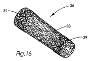
その他の実施形態(図16)においては、構造要素(39)を極めて多孔性の伸長された自己密着ウェブ材料(38)と組合せて、複合構造(36)を形成される。構造要素は、非生体吸収性及び/又は生体吸収性材料で作ることができる。該構造要素は、伸長された自己密着ウェブ材料の片面又は両面上に設置可能である。構造要素は同様に、ウェブ材料内部に設置することもできる。 In another embodiment (FIG. 16), the structural element (39) is combined with a highly porous stretched self-cohered web material (38) to form a composite structure (36). The structural element can be made of a non-bioabsorbable and / or bioabsorbable material. The structural element can be placed on one or both sides of the stretched self-adhering web material. The structural element can also be placed inside the web material.
本発明の伸長された自己密着ウェブ材料の高い多孔率は、フィラメントをさらに一層大きく引き離す手順にウェブ材料を付すことにより、さらに増大させることができる。該手順は同様に、伸長されたウェブ材料の連続フィラメントを破砕させ得る。本発明のこれらの極めて多孔性の伸長された自己密着ウェブ材料は、非常に高い血栓形成特性を有することが示されてきた。好ましい形態では、該ウェブ材料(49)は、「綿球」の外観を有する(図19)。これらの可逆的に圧縮可能な「血栓形成綿球」(49)を単数又は複数の送達システム(48)例えばカテーテルと組合せて、出血又は動脈瘤形成部位に移植することができる(図20)。金属バンド(図19A−B)といった付加的要素を、視覚化補助又は機械的支持体として極めて多孔性の伸長された自己密着ウェブ材料に加えることが可能である。医療用デバイスのための1構成要素として使用された場合、これらの極めて多孔性の血栓形成性ウェブ材料は、該デバイスとその周囲の解剖学的構造及び組織の間のシールを提供することができる。 The high porosity of the stretched self-cohered web material of the present invention can be further increased by subjecting the web material to a procedure that pulls the filaments further apart. The procedure can also break a continuous filament of stretched web material. These highly porous stretched self-cohered web materials of the present invention have been shown to have very high thrombus formation properties. In a preferred form, the web material (49) has the appearance of a “cotton ball” (FIG. 19). These reversibly compressible “thrombogenic cotton balls” (49) can be combined with one or more delivery systems (48), eg, catheters, and implanted at the site of bleeding or aneurysm formation (FIG. 20). Additional elements such as metal bands (FIGS. 19A-B) can be added to the highly porous stretched self-cohered web material as a visualization aid or mechanical support. When used as a component for a medical device, these highly porous thrombogenic web materials can provide a seal between the device and its surrounding anatomy and tissue. .
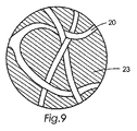
本発明の極めて多孔性のウェブの伸長自己密着ウェブ材料(20)と、さまざまな化学的構成要素(23)を組合せることができる(図9)。該化学的構成要素は、極めて多孔性のウェブ材料を構成する重合体材料の表面上に配置可能である。該化学的構成要素を、ウェブ材料の空隙空間又は気孔内に配置することもできる。化学組成物は、ヒドロゲル材料といったような適度に粘性ある化学組成物である。生物学的に活性な物質(27)を付加的な化学的構成要素(図9A)と組合せることができる(図9A)。例えばヒドロゲル材料の場合、生物学的に活性な物質はヒドロゲル材料から直接放出されるか又はヒドロゲル材料として放出され得、下にあるウェブ材料は被移植者の体により生体吸収される。好ましい化学的構成要素はヒドロゲル材料の形をしている。 Various chemical components (23) can be combined with the highly porous web stretch self-cohered web material (20) of the present invention (FIG. 9). The chemical component can be disposed on the surface of the polymeric material that constitutes the highly porous web material. The chemical component can also be placed in void spaces or pores in the web material. The chemical composition is a reasonably viscous chemical composition such as a hydrogel material. Biologically active substances (27) can be combined with additional chemical components (FIG. 9A) (FIG. 9A). For example, in the case of a hydrogel material, the biologically active substance can be released directly from or as a hydrogel material, and the underlying web material is bioabsorbed by the recipient's body. A preferred chemical component is in the form of a hydrogel material.
適切なヒドロゲル材料としては、単独又は組合せた形で、ポリビニルアルコール、ポリエチレングリコール、ポリプロピレングリコール、デキストラン、アガロース、アルギナート、カルボキシメチルセルロース、ヒアルロン酸、ポリアクリルアミド、ポリグリシドール、ポリ(ビニルアルコール−コ−エチレン)、ポリ(エチレングリコール−コ−プロピレングリコール)、ポリ(酢酸ビニル−コ−ビニルアルコール)、ポリ(テトラフルオロエチレン−コ−ビニルアルコール)、ポリ(アクリロニトリル−コ−アクリルアミド)、ポリ(アクリロニトリル−コ−アクリル酸−アクリルアミジン)、ポリ(アクリロニトリル−コ−アクリル酸−コ−アクリルアミジン)、ポリアクリル酸、ポリ−リジン、ポリエチレンイミン、ポリビニルピロリドン、ポリヒドロキシエチルメタクリラート、ポリスルホン、メルカプトシラン、アミノシラン、ヒドロキシルシラン、ポリアリルアミン、ポリアミノエチルメタクリラート、ポリオルニチン、ポリアミノアクリルアミド、ポリアクロレイン、アクリルオキシスクシンイミド又はそれらの共重合体が含まれるが、これに制限されるわけではない。親水性重合体を溶解させるための適切な溶媒としては、水、アルコール、ジオキサン、ジメチルホルムアミド、テトラヒドロフラン及びアセトニトリルなどが含まれるが、これに制限されるわけではない。 Suitable hydrogel materials include polyvinyl alcohol, polyethylene glycol, polypropylene glycol, dextran, agarose, alginate, carboxymethylcellulose, hyaluronic acid, polyacrylamide, polyglycidol, poly (vinyl alcohol-co-ethylene), alone or in combination. , Poly (ethylene glycol-co-propylene glycol), poly (vinyl acetate-co-vinyl alcohol), poly (tetrafluoroethylene-co-vinyl alcohol), poly (acrylonitrile-co-acrylamide), poly (acrylonitrile-co- (Acrylic acid-acrylamidine), poly (acrylonitrile-co-acrylic acid-co-acrylamidine), polyacrylic acid, poly-lysine, polyethyleneimine, This includes redone, polyhydroxyethyl methacrylate, polysulfone, mercaptosilane, aminosilane, hydroxylsilane, polyallylamine, polyaminoethyl methacrylate, polyornithine, polyaminoacrylamide, polyacrolein, acryloxysuccinimide or copolymers thereof. It is not limited to. Suitable solvents for dissolving the hydrophilic polymer include, but are not limited to, water, alcohol, dioxane, dimethylformamide, tetrahydrofuran and acetonitrile.
任意には、組成物は、ウェブ材料と組合わされた後、化学的に改変され得る。これらの化学的改変は、組成物自体の上の化学的反応基又はウェブ材料の重合体成分と相互作用する化学的反応基であり得る。これらの組成物に対する化学的改変は、さらなるその他の化学組成物例えば生物学的に活性な物質(27)を化学的に結合させるための付着部位として役立ち得る。これらの「生物活性物質」としては、酵素、有機触媒、リボザイム、有機金属、タンパク質、糖タンパク質、ペプチド、ポリアミン酸、抗体、核酸、ステロイド分子、抗生物質、抗真菌薬、サイトカイン、炭水化物、疏油性物質、脂質、細胞外基質材料及び/又はその個々の構成成分、調合薬、及び治療薬が含まれる。好ましい化学ベースの生物活性物質はデキサメタゾンである。細胞例えば哺乳動物細胞、爬虫類細胞、両生類細胞、鳥類細胞、昆虫細胞、プランクトン細胞、非哺乳動物海洋脊椎動物及び無脊椎動物由来の細胞、植物細胞、微生物細胞、原生生物、遺伝子操作されている細胞及びオルガネラ、例えばミトコンドリアも同様に生物活性物質である。さらには、非細胞性の生物学的実体、例えばウイルス、ビレノス(virenos)、及びプリオンも生物活性物質とみなされる。 Optionally, the composition can be chemically modified after being combined with the web material. These chemical modifications can be chemically reactive groups on the composition itself or chemically reactive groups that interact with the polymeric component of the web material. Chemical modifications to these compositions can serve as attachment sites for chemically binding still other chemical compositions such as biologically active substances (27). These "bioactive substances" include enzymes, organic catalysts, ribozymes, organometallics, proteins, glycoproteins, peptides, polyamic acids, antibodies, nucleic acids, steroid molecules, antibiotics, antifungals, cytokines, carbohydrates, and oleaginous Substances, lipids, extracellular matrix materials and / or their individual components, pharmaceuticals, and therapeutics are included. A preferred chemically based bioactive substance is dexamethasone. Cells such as mammalian cells, reptile cells, amphibian cells, avian cells, insect cells, plankton cells, cells from non-mammalian marine vertebrates and invertebrates, plant cells, microbial cells, protists, genetically engineered cells And organelles, such as mitochondria, are also biologically active substances. In addition, non-cellular biological entities such as viruses, virenos, and prions are also considered bioactive substances.
以下の例は、本発明のいくつかの態様を例示する目的で内含されており、制限的なものとみなされるべきではない。 The following examples are included for purposes of illustrating some aspects of the present invention and should not be considered limiting.
例1
この例は、本発明の物品の形成について記述する。最初に、アニールされていない不織自己密着重合体前躯体ウェブを形成した。前駆体ウェブ材料をわずかに加熱し、ウェブ材料の多孔率を増大させるべく単一の又は1軸の方向での伸長に付した。極めて多孔性の自己密着ウェブ材料を次に熱で硬化させた。
Example 1
This example describes the formation of an article of the present invention. Initially, an unannealed nonwoven self-adhering polymer precursor web was formed. The precursor web material was slightly heated and subjected to stretching in a single or uniaxial direction to increase the porosity of the web material. The highly porous self-adhering web material was then cured with heat.
前駆体ウェブ材料を、67%ポリ(グリコリド)及び33%ポリ(トリメチレンカーボナート)(w/w)のセグメント化3ブロック共重合体(67%PGA:33%TMC)で形成させた。該共重合体は、Tyco Healthcare Group LPの一部署であるUnitedStates Surgical(Norwalk、Connecticut、US)から樹脂成型品で入手可能である。この重合体は、ポリグリコナートと一般に呼ばれており、歴史的には前Davis&Geck(Danbury、Connecticut)を通して入手可能であった。標準的な67%PGA:33%TMC樹脂ロットは、本書に参考として内含されている米国特許第6,165,217号(U.S. Patent No. 6,165,217 )の中でHayesが先に特徴づけしたものである。「67:33−PGA:TMC」樹脂材料を特徴づけするプロセスが、本書で繰返し述べられる。 The precursor web material was formed with a segmented triblock copolymer (67% PGA: 33% TMC) of 67% poly (glycolide) and 33% poly (trimethylene carbonate) (w / w). The copolymer is available as a resin molded product from United States Surgical (Norwalk, Connecticut, US), a division of Tyco Healthcare Group LP. This polymer is commonly referred to as polyglyconate and has historically been available through former Davis & Geck (Danbury, Connecticut). A standard 67% PGA: 33% TMC resin lot was previously characterized by Hayes in US Pat. No. 6,165,217 (US Patent No. 6,165,217), incorporated herein by reference. It is. The process of characterizing the “67: 33-PGA: TMC” resin material is repeatedly described herein.
獲得した共重合体約25mgを25mlのヘキサフルオロイソプロパノール(HFIP)中に溶解させた。このように生産した希釈溶液は、30℃(+/−0.05℃)に設定した水浴中に浸漬させたCannon-Ubelodde粘度計で測定される1.53dl/gの固有粘度(IV)を有していた。 About 25 mg of the obtained copolymer was dissolved in 25 ml of hexafluoroisopropanol (HFIP). The diluted solution thus produced has an intrinsic viscosity (IV) of 1.53 dl / g measured with a Cannon-Ubelodde viscometer immersed in a water bath set at 30 ° C. (+/− 0.05 ° C.). Had.
アルミニウムの示差走査熱量計(DSC)試料皿の中に約10mgの獲得した共重合体を入れ、カバーし、摂氏マイナス40度(−40℃)という低い温度までの試料冷却を提供できるIntracoolerII冷却ユニットの備わったパーキンエルマーPSC7を用いて分析した。2分間180℃で試料を予備コンディショニングした後、試料を、計器が提供する最高速度(−500℃/分の設定値)で冷却し、10℃/分の走査速度で、摂氏マイナス40度(−40℃)から摂氏250度まで走査した。この初期走査の完了後、試料を、計器が提供する最高速度(−500℃/分に設定値)で直ちに冷却した。同じ温度範囲にわたり同じ試料に対し2回目の類似の走査に着手した。走査を完了し5分間250℃に熱を維持した後、試料を再び、計器が提供する最高速度で冷却し、3回目の走査に着手した。 Intracooler II refrigeration unit that can cover and cover about 10 mg of the obtained copolymer in an aluminum differential scanning calorimeter (DSC) sample pan and provide sample cooling to temperatures as low as minus 40 degrees Celsius (−40 ° C.) Analysis was performed using a Perkin Elmer PSC7 equipped with After preconditioning the sample at 180 ° C. for 2 minutes, the sample is cooled at the maximum rate the instrument provides (−500 ° C./min setting) and minus 10 degrees Celsius (− 40 degrees Celsius) to 250 degrees Celsius. After completion of this initial scan, the sample was immediately cooled at the maximum rate provided by the instrument (set at -500 ° C / min). A second similar scan was undertaken for the same sample over the same temperature range. After completing the scan and maintaining heat at 250 ° C. for 5 minutes, the sample was again cooled at the maximum rate provided by the instrument and the third scan was initiated.
観察されたガラス転移温度(Tg)、秩序−無秩序遷移温度(Todt)、結晶化発熱量及び溶融吸熱量について、各走査を分析した。結果は、表1に要約されている。 Each scan was analyzed for the observed glass transition temperature (T g ), order-disorder transition temperature (T odt ), crystallization exotherm and melt endotherm. The results are summarized in Table 1.

前駆体ウェブ材料への加工用の共重合体樹脂を調製するために、115℃〜135℃の間で真空(<40mmHg)下で一晩、約100グラムの共重合体を加熱した。4mmの穴を有するスクリーンの備わった造粒機(Rapid Gtanulator、Rockford、Illinois、USA、型式611−SR)を通して共重合体を粉砕することで、樹脂をペレット化した。 To prepare a copolymer resin for processing into a precursor web material, approximately 100 grams of the copolymer was heated overnight between 115 ° C. and 135 ° C. under vacuum (<40 mm Hg). The resin was pelletized by grinding the copolymer through a granulator equipped with a 4 mm hole screen (Rapid Gtanulator, Rockford, Illinois, USA, model 611-SR).
付属の繊維スピンパックアセンブリ(J.J.Jenkins、Inc.、Matthews、NC、USA)を伴う半インチスクリュー押出し機(Randcastle Extrusion Systems、Inc、Cedan Grove、NewJersey、USA、型式RCP−Q500)を得た。スピンパックアセンブリの底部には、直径2.06cm(0.812インチ)の円形形態に配置された直径0.33mm(0.013インチ)のダイ開口部で構成された7孔口小型スピナ(図5中の「スピンパック」参照)がついていた。スピンパックを250℃〜270℃の間の温度に設定した。この特定の温度は、樹脂の固有粘度特性により左右された。 A half inch screw extruder (Randcastle Extrusion Systems, Inc, Cedan Grove, New Jersey, USA, model RCP-Q500) with attached fiber spin pack assembly (J.J. Jenkins, Inc., Matthews, NC, USA) was obtained. At the bottom of the spin pack assembly is a 7-hole small spinner (Fig. 5) (see “Spin Pack”). The spin pack was set to a temperature between 250 ° C and 270 ° C. This particular temperature depended on the inherent viscosity characteristics of the resin.
Vortec型式902TRANSVECTOR(Vortec Corporation-Cincinnati、Ohio USA)を保持する調整可能なアームをスピンパックに取付け、スクリーンファブリック収集ベルトの走行方向と心合せして、紡糸口金の基部の下にこれを位置づけした(図5)。TRANSVECTOR(登録商標)入口の上面を、約2.5〜3.8cm(1.0〜1.5インチ)の調整された距離「A」(図5)のところでダイ開口部の下で芯出しした。TRANSVECTOR(登録商標)を移動する巻取りベルトと同じ方向にファブリック収集装置を横断して揺動させる機械的器具の上に、アームを組立てた。アームは、一秒あたり約0.58フル掃引サイクル(1分あたり約35フルサイクル)の速度の振動数で、中心から約5度外れた角度間で揺動した。約50〜55psi(0.34〜0.38MPa)の圧縮空気供給源にTRANSVECTOR(登録商標)を接続した。圧縮空気は、室温(20〜25℃)すなわち、重合体のTodtを超える温度であった。作動中、圧縮空気を、TRANSVECTOR(登録商標)の吸入口内に導入し、加速させた。加速した空気流は、付加的な空気を多孔口ダイの部域から入口の中に引き込んだ。 An adjustable arm holding a Vortec model 902 TRANSVECTOR (Vortec Corporation-Cincinnati, Ohio USA) was attached to the spin pack and aligned with the direction of travel of the screen fabric collection belt and positioned under the base of the spinneret ( FIG. 5). Center the top surface of the TRANSVECTOR® entrance under the die opening at an adjusted distance “A” (FIG. 5) of about 2.5 to 3.8 cm (1.0 to 1.5 inches). did. The arm was assembled on a mechanical instrument that was swung across the fabric collector in the same direction as the winding belt moving the TRANSVECTOR®. The arm swung between angles about 5 degrees off center with a frequency of about 0.58 full sweep cycles per second (about 35 full cycles per minute). The TRANSVECTOR® was connected to a compressed air source of about 50-55 psi (0.34-0.38 MPa). The compressed air was at room temperature (20-25 ° C.), that is, at a temperature above the polymer Toodt . During operation, compressed air was introduced into the TRANSVECTOR® inlet and accelerated. The accelerated air flow pulled additional air from the perforated die area into the inlet.
次に、真空乾燥したペレット化された共重合体をスクリュー押出し機(101)内に、そして図5に例示されているような紡糸口金(102)のクロスヘッドを通して補給した。溶融した共重合体は7つの個々のフィラメント(105)の形で紡糸口金から退出した。TRANSVECTOR(登録商標)入口(103)に進入する空気流の影響を受けた状態になるにつれて、フィラメントは、空気同伴の無い場合に比べて著しく高い速度でTRANSVECTOR(登録商標)を通って加速された。加速したフィラメントは次に、TRANSVECTOR(登録商標)の出口から“107”66cm(26インチ)の距離のところにあり約20.4cm/分(1分あたり0.67フィート)の速度で移動するスクリーンファブリック収集ベルト(106)上に蓄積されて、前駆体ウェブ材料(108)を形成する。ベルトの速度を増大させるとさらに薄いウェブ材料が生産され、一方ベルト速度を低下させると、さらに厚いウェブ材料が生産された。 The vacuum dried pelletized copolymer was then replenished into the screw extruder (101) and through the spinhead (102) crosshead as illustrated in FIG. The molten copolymer exited the spinneret in the form of seven individual filaments (105). As it became affected by the air flow entering the TRANSVECTOR® inlet (103), the filaments were accelerated through the TRANSVECTOR® at a significantly higher rate than without air entrainment. . The accelerated filament is then screened at a speed of approximately 20.4 cm / min (0.67 feet per minute) at a distance of “107” 66 cm (26 inches) from the TRANSVECTOR® exit. Accumulated on the fabric collection belt (106) to form the precursor web material (108). Increasing the belt speed produced a thinner web material, while decreasing the belt speed produced a thicker web material.
結果として得られる収集ベルト上に蓄積したアニールされていない未伸長不織フィラメント状自己密着前駆体ウェブ材料は、ベルトの移動方向に沿って比較的一貫性あるロフトを有し、かつ約3.2インチの「可使幅」を有していた。「可使幅」というのは、巨視的な視覚レベル及び細かい微視的レベルで最大の一貫性をもつ前駆体ウェブ材料の内部部分を意味する。「可使幅」の外側の前駆体ウェブ材料の部分は、ベルトの移動方向と一致して観察した場合に中心線のいずれかの側で全体的ウェブの相対高さ及び密度が減少するような形で蓄積するフィラメントを有する。本書で報告されている面積密度は、「可使幅」をもつウェブの領域から獲得した代表的試料から得られたものである。 The resulting unannealed unstretched non-woven filamentary self-adhering precursor web material that has accumulated on the collecting belt has a relatively consistent loft along the direction of belt travel and is about 3.2. It had an “usable width” of inches. “Working width” means the internal portion of the precursor web material that has the greatest consistency at the macroscopic and fine microscopic levels. The portion of the precursor web material outside of the “usable width” is such that the overall web relative height and density is reduced on either side of the centerline when observed in line with the direction of belt travel. Has filaments that accumulate in shape. The area density reported in this document was obtained from a representative sample obtained from an area of the web having a “usable width”.
周囲温度で10秒超の間冷却した後、前躯体ウェブをファブリックベルトから取り出した。検査の後、材料は触覚的にしなやかさがあり、密着した繊維質ウェブであり、個々の構成要素繊維は、穏やかな取扱いに付した場合ウェブからほぐれる又は分離することはないように思われた。フィラメントは混じり合い接触点で接着されて、アニールされていない(すなわち最小限にしか結晶していないか又は「未硬化」)、未伸長の不織自己密着前駆体ウェブ材料を形成した。 After cooling for more than 10 seconds at ambient temperature, the precursor web was removed from the fabric belt. After inspection, the material was tactilely pliable and was a coherent fibrous web and the individual component fibers did not appear to loosen or separate from the web when subjected to gentle handling. . The filaments were mixed and bonded at the point of contact to form an unstretched nonwoven self-adhered precursor web material that was not annealed (ie, minimally crystallized or “uncured”).
この要領で生産された前躯体ウェブは、標準的に、Hayesに対し交付され本書に参考として内含されている米国特許第6,165,217号(U.S. Patent No. 6,165,217)の例2で記述されているものと類似の固有粘度(IV)値及び結晶化発熱量ピークを有している。この例の特に関係のある部分を本書中に以下の通りに複製する。 The precursor web produced in this manner is typically described in Example 2 of US Patent No. 6,165,217 (US Patent No. 6,165,217) issued to Hayes and incorporated herein by reference. It has an intrinsic viscosity (IV) value and a crystallization exotherm peak similar to those described above. The particularly relevant part of this example is reproduced in this document as follows.
固有粘度
希釈溶液を作るため、25mlのヘキサフルオロイソプロパノール(HFIP)に中に約29mgの上述の前躯体ウェブを溶解させた。該溶液は、30℃(+/−0.05℃)の水浴中に浸漬させたCanon Ubbelohde粘度計を用いて測定した場合に0.97dl/gの固有粘度(IV)を有していた。従って、IVは加工の間に、ペレット化された共重合体内での1.53dl/gの初期値から前躯体ウェブ内の0.97dl/gの値まで降下したことが観察された。
To make an intrinsic viscosity dilution solution, about 29 mg of the above precursor web was dissolved in 25 ml of hexafluoroisopropanol (HFIP). The solution had an intrinsic viscosity (IV) of 0.97 dl / g as measured using a Canon Ubbelohde viscometer immersed in a 30 ° C. (+/− 0.05 ° C.) water bath. Thus, it was observed that IV dropped during processing from an initial value of 1.53 dl / g in the pelletized copolymer to a value of 0.97 dl / g in the precursor web.
熱特性
パーキンエルマーDSC7示差走査熱量計(DSC)を用いたその熱分析を可能にするため、適切にサイズ決定された試料を上述の前躯体ウェブから得た。10℃/分で走査を実施し、計器の温度をIntracoolerII冷凍ユニットで加減した。摂氏マイナス20度(−20℃)と250℃の間で一回の走査を実施し、以下の結果(TABLE2)を得た。
Thermal properties A suitably sized sample was obtained from the precursor web described above to allow its thermal analysis using a Perkin Elmer DSC7 differential scanning calorimeter (DSC). Scanning was performed at 10 ° C./min, and the temperature of the instrument was adjusted with an Intracooler II refrigeration unit. A single scan was performed between minus 20 degrees Celsius (−20 ° C.) and 250 ° C., and the following result (TABLE2) was obtained.
本書で報告されている秩序−無秩序遷移温度(Todt)は、走査の基線内で1グラム摂氏度あたり(J/g*℃)0.1ジュール超の偏向によって表わされる通り、異なる熱容量レベル間の変曲点で発生している。このTodtは、それぞれの単独重合体のガラス転移温度(Tg)の間の1つの温度で発生し、Fox方程式によって大まかに近似される。この特定の例においては、前駆体ウェブ試料は、約16℃で秩序−無秩序遷移を、そして約70℃で始まる結晶化発熱を示した。完全供試体結晶化度は、ジュール/グラム(J/g)単位のエンタルピーにより定量化される溶融吸熱下の面積と正比例と考えられる。この前駆体ウェブの熱走査の一般的特性は、以上で言及した’217特許の図3中に見ることができる。 The order-disorder transition temperature (T odt ) reported in this document is between different heat capacity levels as represented by a deflection of more than 0.1 Joule per gram Celsius (J / g * ° C.) within the baseline of the scan. It occurs at the inflection point. The T odt occurs at one temperature between the glass transition temperatures of homopolymers (T g), it is roughly approximated by the Fox equation. In this particular example, the precursor web sample exhibited an order-disorder transition at about 16 ° C. and a crystallization exotherm beginning at about 70 ° C. The complete specimen crystallinity is considered to be directly proportional to the area under melt endotherm quantified by the enthalpy in joules / gram (J / g). The general characteristics of this precursor web thermal scan can be seen in FIG. 3 of the '217 patent referred to above.
ウェブが、電力消費ベースのDSCシステムでの上述の評価を通して測定されるように前駆体ウェブの結晶化発熱エンタルピーの実質的削減を導くことになるような熱又は時間の組合せに曝露されないようにした上で、次に、前駆体ウェブの矩形セグメントの相対する端部を拘束下に置き、単一の又は一軸の横方向(すなわち前駆体ウェブの長い方の長さから約90度の方向)で伸長した。 The web was not exposed to a combination of heat or time that would lead to a substantial reduction in the crystallization exotherm enthalpy of the precursor web as measured through the above evaluation in a power consumption based DSC system. Above, then, the opposite ends of the rectangular segments of the precursor web are placed under restraint in a single or uniaxial lateral direction (ie, about 90 degrees from the longer length of the precursor web). Elongated.
本発明の極めて多孔性の伸長された自己密着ウェブ材料は、ピングリップ及び3つの電気加熱ゾーンを備えた横方向延伸/伸長機を用いて作られた。かかる機械は、長手方向に移動しながら支持金属シートの表面を横断して横方向に延伸する能力をもつ調整可能なテンター又はステンターフレームとしても知られている。広い調整可能性のため、本書で記述されている機能を果たすことのできるさまざまな機械が数多くの供給業者から入手可能であり、その1つがMonforts、A.TextiImaschinen Gmb H&Co KG、Moechengladbach、Germanyである。 The highly porous stretched self-cohered web material of the present invention was made using a transverse stretch / stretch machine equipped with a pin grip and three electrical heating zones. Such machines are also known as adjustable tenters or stenter frames that have the ability to stretch transversely across the surface of the supporting metal sheet while moving longitudinally. Due to wide adjustability, various machines are available from numerous suppliers that can perform the functions described in this document, one of which is Monforts, A. TextiImaschinen Gmb H & Co KG, Moechengladbach, Germany .
この特定のユニットには、それぞれ長さ24、6及び24インチ(61、15.2及び61cm)の3枚の逐次的共同加熱プラテンが備わっている。該加熱プラテンは、ウェブ材料が通過する加熱ゾーンを作り上げた。長さ13インチ(33cm)の伸長−転移領域の前縁は、第1の加熱ゾーンの前縁から11インチ(27.9cm)のところで始まった。初期補給速度は1分あたり1フィート(30.48cm)であった。
This particular unit is equipped with three sequential co-heating platens of
初期伸長作業においては、伸長機の第3のつまり最後の下流側のゾーンのみが120℃の温度まで加熱された。しかしながら、第3ゾーンからの熱は、前駆体ウェブが伸長される前に暖められるような形で、隣接する第2及び第1のゾーンに漸進的に侵入するということが予期せず発見された。なかんずく、最終的な極めて多孔性のウェブ材料の均質性は漸進的に改善されることになった。前駆体ウェブ材料は、2:1、3:1、4:1、5:1及び6:1の比で伸長された。横方向伸長器具のゾーン1が50℃の温度に設定され前駆体ウェブ材料が6:1の比で伸長された場合に、好ましい材料が形成された。
In the initial extension operation, only the third or last downstream zone of the extender was heated to a temperature of 120 ° C. However, it was unexpectedly discovered that the heat from the third zone gradually enters the adjacent second and first zones in such a way that the precursor web is warmed before it is stretched. . Among other things, the homogeneity of the final highly porous web material has been progressively improved. The precursor web material was stretched at ratios of 2: 1, 3: 1, 4: 1, 5: 1 and 6: 1. A preferred material was formed when
約1分間約120℃の温度で伸長済みウェブを熱硬化させた後、本発明の極めて多孔性の自己密着ウェブ材料を形成させ、室温まで冷却させた。本発明の材料の各片は、アニールされていない状態にある類似のウェブの予熱及び伸長無しで作られた類似の不織自己密着ウェブよりもさらに多孔性、しなやかさ、ロフト、コンプライアンスそして見かけの均質性が高いことが発見された。 After thermosetting the stretched web at a temperature of about 120 ° C. for about 1 minute, the highly porous self-cohered web material of the present invention was formed and allowed to cool to room temperature. Each piece of material of the present invention is more porous, supple, loft, compliant and apparent than a similar nonwoven self-adhering web made without preheating and stretching of a similar web in an unannealed state. It was discovered that the homogeneity is high.
伸長器具内の各々の連続する加熱ゾーンについて約50℃、75℃及び125℃に設定された予熱済みプラテンを用いて、8:1及び10:1の比で、前駆体ウェブ材料の付加的な矩形断面を伸長した。最初の2つの熱ゾーン設定値は、前駆体ウェブ材料の信頼性の高い「予備加温」を提供した。’217特許の中で報告されたTodtを超える温度は、前駆体ウェブ材料の共重合体分子の移動度を促進し、より一貫性ある最終製品を提供するのに充分であった。第3の加熱されたゾーンは、最終的ウェブ材料をアニール又は熱硬化するべく’217特許の範囲内で記述されている結晶化発熱量ピークの温度(Tcr)を少なくとも近似しそれを上回る確率の高い温度に設定された。 Using a preheated platen set at about 50 ° C., 75 ° C. and 125 ° C. for each successive heating zone in the stretching tool, an additional ratio of precursor web material at a ratio of 8: 1 and 10: 1. The rectangular cross section was elongated. The first two thermal zone settings provided reliable “pre-warming” of the precursor web material. The temperature above To dt reported in the '217 patent was sufficient to promote the mobility of the copolymer molecules of the precursor web material and provide a more consistent end product. The third heated zone has a probability of at least approximating and exceeding the crystallization exotherm peak temperature (Tcr) described within the '217 patent to anneal or thermoset the final web material. A high temperature was set.
例2
この例では、例1で記述されたさまざまなベルト速度及び横方向延伸比を用いて生産された前駆体ウェブが、さまざまなウェブ密度及び伸長又は圧伸比について得られた。加工後に、本発明のこの実施形態の代表的部域の走査型電子顕微鏡写真(SEM)が生成された。本発明の伸長されたウェブ及び該ウェブを含むフィラメントのいくつかの特性が、以下の通りに定量化された。
Example 2
In this example, precursor webs produced using the various belt speeds and transverse stretch ratios described in Example 1 were obtained for various web densities and stretch or draw ratios. After processing, a scanning electron micrograph (SEM) of a representative area of this embodiment of the present invention was generated. Several properties of the stretched web of the present invention and the filaments containing the web were quantified as follows.
本発明の各々のウェブ材料内の伸長されたフィラメントの横断面直径を、SEMの目視検査によって決定した。各々のSEMにおいて、50の伸長されたフィラメントを無作為に選択し、各フィラメントの横断面の直径を測定した。これらのフィラメントの横断面直径の累積的結果は、表3に内含され、図6及び7にまとめられている。伸長比は、「X」の倍数として表わされている。例えば「OX」は、伸長されていない前駆体ウェブ材料を意味する。「4X」は4:1の伸長比を意味する。ウェブの作表された特長は、平均、中央、最大及び最小繊維直径である。さらに、横断面直径が20ミクロン未満であることがわかった50の繊維の数及び百分率が作表された。 The cross-sectional diameter of the elongated filaments within each web material of the present invention was determined by visual inspection of the SEM. In each SEM, 50 elongated filaments were randomly selected and the cross-sectional diameter of each filament was measured. The cumulative results of the cross-sectional diameters of these filaments are included in Table 3 and are summarized in FIGS. The stretch ratio is expressed as a multiple of “X”. For example, “OX” refers to an unstretched precursor web material. “4X” means a 4: 1 stretch ratio. The tabulated features of the web are average, center, maximum and minimum fiber diameter. In addition, the number and percentage of 50 fibers found to have a cross-sectional diameter of less than 20 microns was tabulated.
この方法で評価した場合、アニールされていない未伸長の前駆体ウェブ(OX)の中の全ての繊維横断面直径は、17〜59ミクロンの間にあることが観察された。さらに、90%を超える繊維が上述の’217特許の中で記述された20及び50ミクロンの範囲内の横断面直径を有していた。繊維直径に対する伸長の効果は、このデータから容易にわかる。未伸長前駆体ウェブのフィラメントの直径は、本発明の伸長プロセスに付した時点で削減可能である。繊維直径の削減は、20ミクロン(例えば5.7%)未満の直径をもつ未伸長ウェブ内の繊維数と、20ミクロン未満の直径をもつ伸長済みウェブの繊維数と比較対照することにより容易にわかる。本発明の伸長された材料内の20ミクロン未満の直径をもつ繊維数は、64パーセント(64%)の平均から81パーセント(81%)の範囲内にある。従って、前駆体ウェブの実質的伸長は、本発明の最終的な伸長されたウェブ材料内の実質的数の繊維における繊維直径の有意な削減をひき起こす。 When evaluated in this manner, all fiber cross-sectional diameters in the unannealed unstretched precursor web (OX) were observed to be between 17-59 microns. In addition, over 90% of the fibers had cross-sectional diameters within the 20 and 50 micron ranges described in the above-mentioned '217 patent. The effect of elongation on fiber diameter is easily seen from this data. The filament diameter of the unstretched precursor web can be reduced when subjected to the stretching process of the present invention. Fiber diameter reduction is facilitated by comparing and contrasting the number of fibers in an unstretched web with a diameter less than 20 microns (eg, 5.7%) and the number of fibers in an stretched web with a diameter less than 20 microns. Recognize. The number of fibers having a diameter of less than 20 microns within the stretched material of the present invention is in the range of an average of 64 percent (64%) to 81 percent (81%). Thus, substantial elongation of the precursor web causes a significant reduction in fiber diameter in a substantial number of fibers within the final stretched web material of the present invention.
これらのウェブは単一方向つまり「一軸」式に伸長又は引抜きれたことから、この同じデータから、伸長されたウェブ内の繊維の20〜40パーセントが20ミクロン超の直径を有することに注目すべきである。伸長されたウェブ内部の繊維直径のこの混合の結果、ウェブ材料の全体的ロフトは増大することになる。伸長されたウェブ材料のロフトの増大は、ウェブの面積密度及び体積密度の両方の減少と相関関係をもつ。体積密度は直径多孔率と関係する。本発明のウェブ材料は、類似の未伸長ウェブ材料に比べて増大した多孔率を有する。多孔率を増大させそれに対応して体積密度を削減することで、ウェブ構造内部のすき間空間は最大になる。これらの特長は、宿主細胞のウェブ材料内への浸潤の機会を増大させる。本発明のウェブ材料に存在する細胞の数及びタイプは、ウェブ材料の生体吸収に対し直接的な効果を有する。 Since these webs were stretched or drawn in a unidirectional or “uniaxial” fashion, it is noted from this same data that 20-40 percent of the fibers in the stretched web have a diameter greater than 20 microns. Should. This mixing of the fiber diameter inside the stretched web results in an increase in the overall loft of the web material. The increase in loft of the stretched web material correlates with a decrease in both web area density and volume density. Volume density is related to diameter porosity. The web material of the present invention has an increased porosity compared to a similar unstretched web material. By increasing the porosity and correspondingly reducing the volume density, the clearance space inside the web structure is maximized. These features increase the opportunity for infiltration of host cells into the web material. The number and type of cells present in the web material of the present invention has a direct effect on the bioabsorption of the web material.
本発明の伸長プロセスが付与する実際の分子配向を定量化するために、異なる伸長比で作られた本発明のウェブからのさまざまなフィラメントについて、複屈折値を測定した。複屈折値は、光学格子及び円形回転ステージ(例えばNikon Optiphot2−POL)の両方を有するスライド式クォーツウェッジ能力がある偏光顕微鏡を利用して得られた。フィラメント横断面直径及び複屈折値の両方共が、周囲のウェブの光学的影響から能動的又は受動的に隔離されたフィラメントのサンプリングから測定された。 In order to quantify the actual molecular orientation imparted by the stretching process of the present invention, birefringence values were measured for various filaments from the web of the present invention made with different stretch ratios. Birefringence values were obtained using a polarizing microscope with sliding quartz wedge capability having both an optical grating and a circular rotating stage (eg, Nikon Optiphot2-POL). Both filament cross-sectional diameter and birefringence values were measured from sampling of filaments that were actively or passively isolated from the optical effects of the surrounding web.
フィラメントの隔離の間にいかなる物理的ひずみも発生しないようにして、従来の光学顕微鏡検査及び複屈折値を用いて横断面直径を測定した。ミシェル・レビチャートを利用して値を獲得した。このような光学機器は、さまざまな供給業者(例えばNicon America、Melville、NY)から入手可能である。ミシェル・レビチャートも同様に、さまざまな供給業者(例えばThe Mclrone Institnte(Chicago、IL))から入手可能である。 The cross-sectional diameter was measured using conventional optical microscopy and birefringence values so that no physical strain occurred during filament separation. The value was obtained using Michel Levichart. Such optical instruments are available from various suppliers (eg, Nicon America, Melville, NY). Michelle Levichart is similarly available from various suppliers (eg, The Mclrone Institnte (Chicago, IL)).
このようにして得た複屈折値を、フィラメント直径との相関関係について分析した。この関係は、0.8211というR2値で、
Y=0.4726×-0.9979
という方程式により近似され得る冪関数に従うように見えることが発見された(図8参照)。この関係を用いかつ図8を参照すると、20ミクロンの横断面直径をもつフィラメントが約0.024の複屈折値を有するものと予期できるということが決定された。かくして、20ミクロン未満の横断面直径を有するフィラメントは、無理なく0.025超の複屈折値を有すると予期され得る。
The birefringence values thus obtained were analyzed for correlation with filament diameter. This relationship is an R2 value of 0.8211
Y = 0.4726 × -0.9979
It was discovered that it appears to follow a power function that can be approximated by the equation (see FIG. 8). Using this relationship and referring to FIG. 8, it was determined that a filament having a cross-sectional diameter of 20 microns could be expected to have a birefringence value of about 0.024. Thus, filaments having a cross-sectional diameter of less than 20 microns can be expected to have a birefringence value greater than 0.025 without difficulty.
例3
例1に記述されている材料を伸長した結果として、単位面積あたりの重合体材料の量(面積密度)及び単位体積あたりの重合体材料の量(体積密度)の両方が削減された。(0.67フィート/分(20.4cm/分)のベルト速度で生産された)前駆体ウェブを、ウェブ材料を完全にアニール又は「熱硬化」させるべく25分間100℃に設定したオーブン内でさらに加工した。
Example 3
As a result of stretching the material described in Example 1, both the amount of polymer material per unit area (area density) and the amount of polymer material per unit volume (volume density) were reduced. The precursor web (produced at a belt speed of 0.67 ft / min (20.4 cm / min)) was placed in an oven set at 100 ° C. for 25 minutes to fully anneal or “heat cure” the web material. Further processed.
アニールされた未伸長の自己密着前駆体ウェブは実質的に、’217特許内で開示されたウェブ材料に類似していた。前駆体ウェブ材料の熱硬化されたバージョンが、約23mg/cm2の面積密度及び約0.16g/ccの体積密度をもつものと判定された。このタイプのウェブ成形品は、W.L.Gore&Associates,Inc.,Flagstaff, AZから、GORE生体吸収性Seam Guard及びGORE Resolut AdaptLTという商標名で入力可能である。これらの未伸長ウェブ材料の各々は、それぞれ9.7mg/cm2及び8.4mg/cm2の面積密度を有する。各ウェブ材料は同様に、それぞれ0.57g/cc及び0.74g/ccという体積密度を有していた。これは、それぞれ56及び43の多孔性百分率に対応していた。 The annealed, unstretched self-adhering precursor web was substantially similar to the web material disclosed in the '217 patent. A thermoset version of the precursor web material was determined to have an area density of about 23 mg / cm 2 and a volume density of about 0.16 g / cc. This type of web molding can be entered under the trade names GORE Bioabsorbable Seam Guard and GORE Resolut AdaptLT from WL Gore & Associates, Inc., Flagstaff, AZ. Each of these unstretched web material, each having an area density of 9.7 mg / cm 2 and 8.4 mg / cm 2. Each web material likewise had a volume density of 0.57 g / cc and 0.74 g / cc, respectively. This corresponded to a porosity percentage of 56 and 43, respectively.
6:1という比での例1の前駆体ウェブ材料の一軸伸長の後、該材料が約5.3mg/cm2の面積密度を有することを決定した。これは、約75パーセント(75%)の面積密度の変化を表わす。例1の未伸長前駆体ウェブ材料は、0.16g/ccの体積密度を有していた。これと対照的に、例1の伸長されたウェブ材料は0.083g/ccの体積密度を有していた。これは、約50パーセントの体積密度の削減を表わしている。 After uniaxial stretching of the precursor web material of Example 1 at a ratio of 6: 1, it was determined that the material had an area density of about 5.3 mg / cm 2 . This represents an area density change of about 75 percent (75%). The unstretched precursor web material of Example 1 had a volume density of 0.16 g / cc. In contrast, the stretched web material of Example 1 had a volume density of 0.083 g / cc. This represents a volume density reduction of about 50 percent.
完全密度で未伸長の67%PGA:30%TMC(w/w)の重合体(Ppolymer)の比重は、1.30グラム/ccであると報告されてきた(Mukherjee , D. et al;生体吸収性PGAの評価:軟骨細胞の成長のためのTMC足場、抄録第12号、生体材料学会議事録、2005年5月)。この報告された重合体密度値と本発明のウェブ材料の体積密度(Pscaffold)を比較することにより、付加的な構成要素の不在下での全体的多孔性百分率を、以下の関係式から求めることができる:
(Ppolymer−Pscaffold)÷Ppolymer×100。
The specific gravity of full density, unstretched 67% PGA: 30% TMC (w / w) polymer (P polymer ) has been reported to be 1.30 grams / cc (Mukherjee, D. et al; Evaluation of bioresorbable PGA: TMC scaffold for chondrocyte growth,
(P polymer −P scaffold ) ÷ P polymer × 100.
本書で使用される「多孔性百分率」又は単に「多孔率」という用語は、利用可能な多孔率を有効に削減し得る何らかの充填材又はその他の付加された構成要素の包含がない場合に、伸長された自己密着ウェブの外部境界内部に提供される空隙空間として定義される。 As used herein, the term “percentage of porosity” or simply “porosity” refers to stretching in the absence of inclusion of any fillers or other added components that can effectively reduce the available porosity. Is defined as the void space provided within the outer boundary of the formed self-adhering web.
この評価は、例1の前駆体ウェブ材料の伸長が、付加的な構成要素の不在下で88パーセント(88%)から付加的な構成要素の不在下で約94パーセント(94%)までPGA:TMC前駆体ウェブ材料の多孔性百分率を増大させるということを示した。前躯体及び上述の6:1伸長の両方のウェブの付加的な構成要素不在下での結果として得られる多孔性百分率は、表4に提供されている。表4は同様に、伸長の前後のウェブ材料の面積密度、体積密度及び多孔性百分率の要約を提供している。 This evaluation shows that the elongation of the precursor web material of Example 1 is from 88 percent (88%) in the absence of additional components to about 94 percent (94%) in the absence of additional components: It has been shown to increase the porosity percentage of the TMC precursor web material. The resulting porosity percentages in the absence of additional components of both the precursor and the 6: 1 stretched web described above are provided in Table 4. Table 4 also provides a summary of the area density, volume density, and porosity percentage of the web material before and after stretching.
例4
この例は、本発明の一軸伸長された(6:1の伸長比)ウェブ材料のための引張応力−ひずみデータの生成について記述している。該ウェブ材料は、ベルト速度が0.26フィート/分(7.9cm/秒)であったという点を除いて、例1に従って生産された。
Example 4
This example describes the generation of tensile stress-strain data for a uniaxially stretched (6: 1 stretch ratio) web material of the present invention. The web material was produced according to Example 1 except that the belt speed was 0.26 ft / min (7.9 cm / sec).
本発明の伸長されたウェブ材料の試料を「犬用の骨」の形に似た、中央ストリップと拡大した両端部をもつ形状にカットした。犬用の骨の形をした供試体は、ASTMD638IV型について記述されたもののほど半分のサイズを有していた(すなわち、狭い距離の長さが8mmで狭い幅が3mm)。伸縮計及び500ニュートンロードセルの備わったINSTRON(登録商標)引張試験機型式5564号を用いて、試験を実施した。試験機を動作させるために用いられたソフトウェアパッケージは、Merlin、バージョン4.42(Instron Corparation、Norwood、MA)であった。ゲージ長は15.0mmであった。クロスヘッド速度(XHR)は250mm/分であった。データを0.1秒毎に収集した。 A sample of the stretched web material of the present invention was cut into a shape with a central strip and enlarged ends, resembling the shape of a “dog bone”. The canine bone-shaped specimen was half as large as described for ASTM D638 type IV (ie, a narrow distance length of 8 mm and a narrow width of 3 mm). The test was carried out using an INSTRON® tensile tester model 5564 equipped with an extensometer and a 500 Newton load cell. The software package used to operate the tester was Merlin, version 4.42 (Instron Corparation, Norwood, Mass.). The gauge length was 15.0 mm. The crosshead speed (XHR) was 250 mm / min. Data was collected every 0.1 seconds.
より強いクロスウェブ方向と整列するようにその長さが配向された供試体から測定した通りの伸長されたウェブの引き伸ばし百分率(%)及びマトリックス引張応力は、それぞれ32.0%と60MPaであることがわかった。より弱いダウンウェブ方向で測定した通りのその長さで配向された供試体から測定された伸長されたウェブの引き伸ばし百分率(%)及びマトリックス引張応力は、それぞれ84.7%及び3.4MPaであることがわかった。これらの67:33−PGA:TMCウェブについての引張応力の結果は、表5に要約されている。比較目的で、’217特許の中で記述されているような67:33−PGA:TMCのより薄いウェブの機械的特性は、表5の中に内含されている。 The stretched web stretch percentage (%) and matrix tensile stress, as measured from specimens whose length is oriented to align with the stronger crossweb direction, are 32.0% and 60 MPa, respectively. I understood. The stretched web percent stretch and matrix tensile stress measured from specimens oriented at that length as measured in the weaker downweb direction are 84.7% and 3.4 MPa, respectively. I understood it. The tensile stress results for these 67: 33-PGA: TMC webs are summarized in Table 5. For comparison purposes, the mechanical properties of 67: 33-PGA: TMC thinner webs as described in the '217 patent are included in Table 5.
高度の多孔率及び容易に変形されるロフトを有する本発明の材料といったような厚みの測定が疑わしいものであり得る場合、試料内の引張応力を正規化するための手段として、マトリックス引張応力が利用される。テスト材料の面積密度及びその構成要素重合体の比重の利用を通して、マトリックス引張応力アプローチは、測定の困難な多孔性ロフトを、完全密度の構成要素重合体の同等の厚みへと転換する。該削減は、構成要素重合体の比重でウェブの体積密度を除したものに正比例する。この等価の重合体厚みは次に、引張応力の計算において断面積の決定のために利用された。このようなマトリックス引張応力の使用は、多孔性延伸ポリテトラフルオロエチレン(ePTFE)材料の強度を決定する上で利用するため、Bowman et al.に発行された米国特許第4,482,516号(U.S. Patent No. 4,482,516)及びGoreに発行された米国特許第3,953,566号(U.S. Patent No. 3,953,566)の両方の中で記述されてきた。 Matrix tensile stress is used as a means to normalize tensile stress in a sample where thickness measurements can be questionable, such as materials of the present invention with high porosity and easily deformed lofts Is done. Through the use of the area density of the test material and the specific gravity of its constituent polymer, the matrix tensile stress approach converts a difficult-to-measure porous loft to the equivalent thickness of a full density constituent polymer. The reduction is directly proportional to the specific gravity of the constituent polymer divided by the volume density of the web. This equivalent polymer thickness was then used to determine the cross-sectional area in the calculation of tensile stress. The use of such matrix tensile stress is utilized in determining the strength of porous expanded polytetrafluoroethylene (ePTFE) material, so Bowman et al. US Pat. No. 4,482,516 (US Pat. No. 4,482,516) and US Pat. No. 3,953,566 (US Pat. No. 3,953,566) issued to Gore. It was.
マトリックス引張応力を得るために、構成要素重合体の比重で多孔性構造の面積密度を除することによって、引張供試体の等価厚みを決定する。次に、応力を決定する上で供試体の実際の厚みの代りにこの値を代入する。かくして:
等価厚み=面積密度/重合体の比重
In order to obtain matrix tensile stress, the equivalent thickness of the tensile specimen is determined by dividing the area density of the porous structure by the specific gravity of the constituent polymer. Next, this value is substituted for the actual thickness of the specimen in determining the stress. Thus:
Equivalent thickness = area density / specific gravity of polymer
構成要素重合体の面積密度及び比重の両方がわかっていることを条件として、多孔性試料の引張応力をマトリックス引張応力値に転換するために等価厚み値を利用することもできる。’217特許の例2においては、67:33−PGA:TMCウェブ材料の両最大引張応力が、供試体の面積密度と共に報告され、それぞれ4.9MPa及び28.1mg/mm2であることがわかった。 The equivalent thickness value can also be used to convert the tensile stress of the porous sample to a matrix tensile stress value, provided that both the area density and specific gravity of the constituent polymer are known. In Example 2 of the '217 patent, both maximum tensile stresses of 67: 33-PGA: TMC web material are reported along with the area density of the specimen and are found to be 4.9 MPa and 28.1 mg / mm 2 , respectively. It was.
かくして、マトリックス引張応力を以下の通りに計算することができる:
データに関してわかるように、本発明のウェブ材料は、きわめて異方性であることが発見され、ダウンウェブ」方向に低減された強度及び有意な引き伸ばしを有していた。換言すると、強度は伸長方向で最高であり、クロスウェブ方向のマトリックス引張応力は、’217特許中に記述された完全に結晶化された未伸長のウェブ材料よりも著しく高いことがわかった。この結果は、PGT:TMCブロック共重合体の分子配向の増大の証拠を提供した。 As can be seen with respect to the data, the web material of the present invention was found to be very anisotropic and had reduced strength and significant stretch in the “downweb” direction. In other words, the strength was highest in the stretch direction and the cross-web direction matrix tensile stress was found to be significantly higher than the fully crystallized unstretched web material described in the '217 patent. This result provided evidence of increased molecular orientation of the PGT: TMC block copolymer.
例5
この例は、50:50のポリ(グリコリド)対ポリ(トリメチレンカーボナート)(w/w)比を有するPGA:TMCのA生体吸収性3ブロック共重合体を用いた本発明の物品の形成について記述している。
Example 5
This example illustrates the formation of an article of the invention using a PGA: TMC A bioabsorbable triblock copolymer having a 50:50 poly (glycolide) to poly (trimethylene carbonate) (w / w) ratio. Is described.
標準的な50%PGA:50%TMC樹脂ロットの合成が、’217特許の中で先に記述されており、本書では以下のように繰り返される。 The synthesis of a standard 50% PGA: 50% TMC resin lot was previously described in the '217 patent and is repeated here as follows.
クラス10,000のクリーンルーム内に位置設定され、最高230℃の温度を維持することのできるSterlingブランドの熱油システム(型式S9016番、Sterling、Inc.,Milwankee、Wis.,USA)に接続された4CVHelicone Mixer(DesignIntegrated Technologies、Warrenton、Va.,USA)を予め清浄して重合体又はその他の残渣をことごとく除去し、その後2時間徹底的に空気乾燥させてから、ミキサーボウルを再度取付けた。乾燥ミキサーを次に140℃まで予熱し、その後パージし、次に実験の過程において最小流量を無水窒素でブランケットした。トリメチレンカーボナート740.7グラムが入ったホイルパッケージを開き、中味を導入しひき続き「6.5」の速度設定値で混合した。10分後、攪拌を停止し、0.228グラムのSnCl2・2H2O触媒と15.71グラムのジエチレングリコール開始剤の組合せ2.73グラムを次に直接溶融したTMCに添加した。混合が推奨され、10分後に温度を160℃まで上昇させ、これを次に30分後に180℃まで上昇させた。さらに30分後、75グラムのグリコリド単量体を添加しその後温度を200℃まで上昇させた。15分後、675グラムのグリコリドを添加し、温度設定値を直ちに220℃に変更した。40分後、重合した生成物を220℃で清潔な放出表面上に排出し、ここで、室温まで冷却するにつれてこれを固化させた。かくして得られた明褐色の重合体を次に、発熱物質を含まないプラスチック袋の中に包装し、その後さらなる分析及び加工に先立ち4.0mmのスクリーンを通して機械的に造粒した。 Located in a Class 10,000 clean room and connected to a Sterling brand hot oil system (model S9016, Sterling, Inc., Milwankee, Wis., USA) capable of maintaining temperatures up to 230 ° C The 4CV Helicone Mixer (DesignIntegrated Technologies, Warrenton, Va., USA) was pre-cleaned to remove any polymer or other residue, and then thoroughly air dried for 2 hours before re-installing the mixer bowl. The drying mixer was then preheated to 140 ° C. and then purged, then blanketed with anhydrous nitrogen during the course of the experiment. The foil package containing 740.7 grams of trimethylene carbonate was opened, the contents were introduced, and then mixed at a speed setting of “6.5”. After 10 minutes, the agitation was stopped and 2.73 grams of a combination of 0.228 grams of SnCl 2 .2H 2 O catalyst and 15.71 grams of diethylene glycol initiator was then added to the directly melted TMC. Mixing was recommended and after 10 minutes the temperature was raised to 160 ° C, which was then raised to 180 ° C after 30 minutes. After another 30 minutes, 75 grams of glycolide monomer was added and the temperature was then raised to 200 ° C. After 15 minutes, 675 grams of glycolide was added and the temperature set point was immediately changed to 220 ° C. After 40 minutes, the polymerized product was discharged onto a clean release surface at 220 ° C. where it solidified as it cooled to room temperature. The light brown polymer thus obtained was then packaged in a pyrogen free plastic bag and then mechanically granulated through a 4.0 mm screen prior to further analysis and processing.
’217特許において、Hayesはさらに、この特定の50%PGA:50%TMC樹脂のロットの固有粘度が0.99dl/gであることを報告した。 In the '217 patent, Hayes further reported that the specific viscosity of this particular 50% PGA: 50% TMC resin lot was 0.99 dl / g.
記述された通りに合成された50%のPGA:50%のTMCの3ブロック共重合体を次に、例1に記述されている通りに造粒し、その後120℃〜130℃で少なくとも15時間真空乾燥させた。例1に記述されている押出し機の中に約250グラムの粉砕重合体を入れ、約230℃〜250℃のダイ温度まで加熱した。幅約3.2インチ(5.08cm)のランダム連続前駆体ウェブ材料を、約20.4cm/分(1分あたり0.67フィート)のベルト速度で獲得した。前駆体ウェブ材料は、例1内で記述されている伸長67:33−PGA:TMC前駆体ウェブ材料と形態学的に類似していた。個々のフィラメントは、接触点で密着した結合を形成し、自己密着ウェブを形成した。このプロセスを通して生産されるウェブ材料のためのフィラメント直径は、25ミクロン乃至40ミクロンの範囲内にあった。’217特許に記されている通り、これらのウェブ材料は標準的に0.9dl/gという固有粘度値を有する。これらのウェブ材料についての標準的DSC値が表6に列挙されている。 A 50% PGA: 50% TMC triblock copolymer synthesized as described was then granulated as described in Example 1 and then at 120 ° C to 130 ° C for at least 15 hours. Vacuum dried. About 250 grams of ground polymer was placed in the extruder described in Example 1 and heated to a die temperature of about 230 ° C to 250 ° C. A random continuous precursor web material of about 3.2 inches (5.08 cm) in width was acquired at a belt speed of about 20.4 cm / min (0.67 feet per minute). The precursor web material was morphologically similar to the stretch 67: 33-PGA: TMC precursor web material described in Example 1. The individual filaments formed intimate bonds at the points of contact to form a self-adhering web. The filament diameter for the web material produced through this process was in the range of 25 to 40 microns. As noted in the '217 patent, these web materials typically have an intrinsic viscosity value of 0.9 dl / g. Standard DSC values for these web materials are listed in Table 6.
アニールされていない不織自己密着前駆体ウェブ材料の伸長を、67:33−PGA:TMC3ブロック共重合体不織自己密着前駆体ウェブ材料について例1で記述されたものと同じ機器及び一軸伸長速度で実施した。未伸長前駆体ウェブが、伸長に先立ちウェブの結晶化発熱エンタルピーの実質的削減に導くことになる熱又は時間の組合せに曝露されないように注意を払った。 The elongation of the unannealed nonwoven self-adhering precursor web material is the same equipment and uniaxial elongation rate as described in Example 1 for the 67: 33-PGA: TMC3 block copolymer nonwoven self-adhering precursor web material. It carried out in. Care was taken that the unstretched precursor web was not exposed to a combination of heat or time that would lead to a substantial reduction in the crystallization exotherm of the web prior to stretching.
例1に記述されている1軸伸長比に加えて、7:1〜10:1の付加的1軸伸長比を実施した。ゾーン1のオーブン温度を摂氏40度(40℃)に設定し、ゾーン3を摂氏85度(85℃)に設定した。摂氏85度(85℃)でゾーン3内に約5分間置いた後、伸長されたウェブの熱硬化が達成された。
In addition to the uniaxial stretch ratio described in Example 1, an additional uniaxial stretch ratio of 7: 1 to 10: 1 was performed.
50:50のPGA:TMC3ブロック共重合体出発材料で作られた本発明のウェブについては、7:1〜10:1の1軸伸長比が、最も高いしなやかさと均質な外観をもつウェブを生産した。 For webs of the present invention made with 50:50 PGA: TMC3 block copolymer starting material, a uniaxial stretch ratio of 7: 1 to 10: 1 produces the web with the highest suppleness and homogeneous appearance. did.
例6
この例は、前駆体ウェブ材料の多重層を用い実質的に直交する方向で層状化された材料を伸長することによる本発明の物品の形成について記述している。
Example 6
This example describes the formation of an article of the present invention by stretching a layered material in a substantially orthogonal direction using multiple layers of precursor web material.
出発材料は、例1に従って作られたアニールされていない未伸長前駆体ウェブ材料の9枚のシートを共に層状化させることによって得られた。9枚の前躯体シートの各々は、1.58ft/分(48cm/分)のベルト速度で生産した。各々の前躯体シートは、約9.0mg/cm2の面積密度と約0.27g/ccの体積密度を有することがわかった。従って、前躯体シート材料の9層は、約81mg/cm2の面積密度及び約0.27g/ccの体積密度を有することが予期されるだろう。 The starting material was obtained by laminating together 9 sheets of unannealed unstretched precursor web material made according to Example 1. Each of the nine precursor sheets was produced at a belt speed of 1.58 ft / min (48 cm / min). Each precursor sheet was found to have an area density of about 9.0 mg / cm 2 and a volume density of about 0.27 g / cc. Thus, nine layers of precursor sheet material would be expected to have an area density of about 81 mg / cm 2 and a volume density of about 0.27 g / cc.
9枚のアニールされていない未伸長前駆体ウェブシートは当初、その幅が一般にウェブの形成につれてそれを巻取るのに用いられる移動ベルトと同じ「流れる方向」にあるような形で配向された。同じように配向された層状化したシートは、3つの加熱されたゾーンがそれぞれ周囲温度、50℃及び120℃に設定されている状態で、オーブンの中で横方向(すなわちアニールされていないウェブの初期配向の方向から約90度の方向)に伸長された。伸長比は6:1であり、伸長速度は一分あたり1フィート(30.5cm/分)であった。 The nine unannealed unstretched precursor web sheets were initially oriented in such a way that their width is generally in the same “flow direction” as the moving belt used to wind the web as it is formed. A similarly oriented layered sheet is produced in the transverse direction (i.e. of the unannealed web) in the oven with the three heated zones set at ambient temperature, 50 ° C and 120 ° C, respectively. It was elongated in the direction of about 90 degrees from the direction of the initial orientation. The stretch ratio was 6: 1 and the stretch rate was 1 foot per minute (30.5 cm / min).
結果は、18mg/cm2の面積密度をもつ本発明の物品であった。これは、前駆体ウェブ材料からほぼ76パーセントの面積密度の削減に相当する。該物品は、0.11g/ccの体積密度を有していた。これは、前駆体ウェブ材料(0.27g/cc)からほぼ60パーセントの体積密度の削減に相当する。このウェブ材料の多孔性百分率は79であった。 The result was an article of the present invention with an area density of 18 mg / cm 2 . This corresponds to a reduction in area density of approximately 76 percent from the precursor web material. The article had a volume density of 0.11 g / cc. This corresponds to a volume density reduction of approximately 60 percent from the precursor web material (0.27 g / cc). The percent porosity of this web material was 79.
前駆体ウェブの引き伸ばし百分率及び完成積層ウェブ材料のマトリックス引張応力を、より強いクロスウェブ方向で測定し、それぞれに64パーセント(64%)及び48MPaであることがわかった。より弱いダウンウェブ方向で測定された本発明の完成積層ウェブの引き伸ばし百分率及びマトリックス引張応力はそれぞれ133パーセント(133%)及び5.2MPaであることがわかった。これらの値は、例1の単層一軸拡張ウェブで観察されたものに比べて大きい。クロスウェブ方向でのマトリックス引張応力も同様に、’217特許で報告された22.7MPa値よりも高いものであった。 The stretch percentage of the precursor web and the matrix tensile stress of the finished laminated web material were measured in the stronger crossweb direction and found to be 64 percent (64%) and 48 MPa, respectively. The stretch percentage and matrix tensile stress of the finished laminated web of the present invention measured in the weaker downweb direction were found to be 133 percent (133%) and 5.2 MPa, respectively. These values are higher than those observed for the single layer uniaxially expanded web of Example 1. The matrix tensile stress in the cross-web direction was also higher than the 22.7 MPa value reported in the '217 patent.
この例の層状化されたウェブ材料は、伸長されていない不織自己密着層状化ウェブ材料に比べて高いしなやかさの及び均質な外観を有していた。 The layered web material of this example had a high supple and uniform appearance compared to the non-stretched non-woven self-adhering layered web material.
例7
この例は、第1の長手方向ウェブ伸長手順とそれに続く同じウェブの後続横方向伸長手順から生産された材料を描写している。このウェブ材料は本書では、「長手方向−横方向伸長ウェブ」と呼ばれる。アニールされていない未伸長自己密着前駆体ウェブ材料は、例1に従って調製され、本発明の材料を形成するために以下の通りに加工された。
Example 7
This example depicts the material produced from a first longitudinal web stretching procedure followed by a subsequent lateral stretching procedure of the same web. This web material is referred to herein as a “longitudinal-transversely stretched web”. An unannealed unstretched self-adhering precursor web material was prepared according to Example 1 and processed as follows to form the material of the present invention.
例1に記述されている通りにDSCパラメータを用いて評価された場合、利用された67:33−PGA:TMC樹脂と結果としてもたらされたアニールされていない前駆体ウェブの両方の熱特性は、表7にまとめられている通りであった。 When evaluated using DSC parameters as described in Example 1, the thermal properties of both the 67: 33-PGA: TMC resin utilized and the resulting unannealed precursor web were , As summarized in Table 7.
主として伸長比に基づいて、この例では、本発明の5種の伸長ウェブを、生産した。類似していない速度調整された補給及び巻取りローラーの間で長手方向で移動する間に支持用3ゾーン加熱金属シートの表面を横断して適当な長さの前駆体ウェブを引抜くことのできる長手方向伸長機を用いて、各々のアニールされていない未伸長前駆体ウェブ材料をまず最初に、未伸長前駆体ウェブの回復のために用いられる収集ベルトの方向と実質的に同じ方向で摂氏20度(20℃)の温度で1.5:1の比で長手方向に伸長させた。この長手方向(例えばx軸方向)をここでは「ダウンウェブ」(DW)方向と呼ぶ。 In this example, five stretch webs of the present invention were produced, mainly based on stretch ratio. Appropriate length of precursor web can be drawn across the surface of the supporting three-zone heated metal sheet while moving longitudinally between dissimilar speed-controlled replenishment and take-up rollers Using a longitudinal stretcher, each unannealed unstretched precursor web material is first placed in a direction substantially the same as the direction of the collection belt used for recovery of the unstretched precursor web. It was stretched in the longitudinal direction at a ratio of 1.5: 1 at a temperature of 20 ° C. This longitudinal direction (eg, the x-axis direction) is referred to herein as the “down web” (DW) direction.
長手方向に伸長されたアニールされていない自己密着ウェブ材料を、次に例1で記述されている加熱プラテン横方向伸長機まで移送した。これらのダウンウェブ伸長された材料の各々をその後、第1の長手方向伸長手順の方向に対し直交する「横断方向」(y軸)で2回目の伸長に付した。この「横断方向」伸長を、ここでは「クロスウェブ」(CW)伸長と呼ぶ、第1の試料(「1B」と呼称する)を2:1の比でクロスウェブで伸長した。次の試料(「2A」)を3:1の比でクロスウェブで伸長した。各々の残った試料(2B、2C及び2D)をそれぞれ3.5:1、4:1及び4.5:1の比でクロスウェブ伸長した。オーブン内の第1及び第3の加熱されたゾーンをそれぞれ摂氏50度(50℃)及び摂氏120度(120℃)に設定した。ゾーン3の温度は、本発明の最終的な伸長されたウェブ材料を完全に熱硬化するために充分なものであった。結果として得られた材料は、実質的なDW拡張性を示した表8に表わされた熱特性によって立証される通り、完全にアニールされたウェブであった。
The longitudinally stretched unannealed self-cohered web material was then transferred to the heated platen transverse stretcher described in Example 1. Each of these downweb stretched materials was then subjected to a second stretch in the “transverse direction” (y-axis) perpendicular to the direction of the first longitudinal stretch procedure. This “cross-direction” stretch, referred to herein as “cross-web” (CW) stretch, was stretched with a cross-web in a 2: 1 ratio to a first sample (referred to as “1B”). The next sample ("2A") was stretched cross-web at a 3: 1 ratio. Each remaining sample (2B, 2C and 2D) was cross-web stretched at ratios of 3.5: 1, 4: 1 and 4.5: 1, respectively. The first and third heated zones in the oven were set to 50 degrees Celsius (50 ° C.) and 120 degrees Celsius (120 ° C.), respectively. The temperature in
完全に硬化した前駆体ウェブと共に(1.5:1)長手方向−(4.5:1)横方向に伸長したウェブ(2D)の物理的及び引張応力−ひずみ特性が、表9に要約されている。 The physical and tensile stress-strain properties of the (1.5: 1) longitudinal- (4.5: 1) transversely stretched web (2D) with the fully cured precursor web are summarized in Table 9. ing.
例8
この例は、本発明の2つの伸長された自己密着ウェブ材料の形成について記述する。ウェブ材料は、加工中に2方向(x軸及びy軸)において同時に2軸伸長された。
Example 8
This example describes the formation of two stretched self-cohered web materials of the present invention. The web material was simultaneously biaxially stretched in two directions (x-axis and y-axis) during processing.
未伸長前駆体ウェブ材料を例1に従って作った。TRANSVECTOR(登録商標)器具を8.5度の紡糸口金角度及び秒速0.46フルサイクルの掃引速度に設定した。結果として得られたアニールされていない未伸長の前駆体ウェブ材料は、約8cm/分のベルト速度で生成された40〜50mg/cm2のウェブ密度で5〜6インチ(12.7cm〜15.2cm)の「可使幅」を有していた。アニールされていない未伸長前駆体ウェブ材料は、ウェブの結晶化発熱エンタルピーの実質的削減を導くと思われる熱又は時間の暫定的組合せに曝露されなかった。 An unstretched precursor web material was made according to Example 1. The TRANSVECTOR® instrument was set to a spinneret angle of 8.5 degrees and a sweep rate of 0.46 full cycle per second. The results as obtained annealed have not unstretched precursor web material, the web density of about 8 cm / min belt speed generated by 40-50 mg / cm 2 5 to 6 inches (12.7cm~15. 2 "). The unannealed unstretched precursor web material was not exposed to a temporary combination of heat or time that would lead to a substantial reduction in the crystallization exotherm enthalpy of the web.
第1の2軸伸長されたウェブ材料を形成するために、アニールされていない前駆体ウェブ材料を2軸伸長するのに、パントグラフを使用した。パントグラフは、一定範囲の速度及び温度(例えば50℃〜300℃)にわたり1軸又は2軸で前駆体ウェブ材料を伸長する能力をもつ機械である。この例で使用されるパントグラフは、4インチ×4インチ(4”×4”)の正方形部片から25インチ×25インチ(25”×25”)の部片へと前駆体ウェブ材料の部片を伸長する能力を有していた。これはx及びyの両軸において6.1:1の伸長比を表わしていた。伸長中に前駆体ウェブ材料を保持するために、パントグラフ上の各アームの最後の半インチにはピンの列が備わっていた。パントグラフ上には合計32本のアーム(つまり各々の側に7本ずつと各コーナーに1本)が存在していた。パントグラフには同様に、加熱されたクラムシェルタイプのプラテンも備わっており、これが、加工中の前駆体ウェブ材料の温度の制御を可能にしていた。 A pantograph was used to biaxially stretch the unannealed precursor web material to form a first biaxially stretched web material. A pantograph is a machine that has the ability to stretch a precursor web material uniaxially or biaxially over a range of speeds and temperatures (eg, 50 ° C. to 300 ° C.). The pantograph used in this example is a portion of precursor web material from a 4 inch x 4 inch (4 "x 4") square piece to a 25 inch x 25 inch (25 "x 25") piece. Had the ability to stretch the piece. This represented an elongation ratio of 6.1: 1 on both the x and y axes. To hold the precursor web material during stretching, the last half inch of each arm on the pantograph was provided with a row of pins. There were a total of 32 arms on the pantograph (ie, 7 on each side and 1 on each corner). The pantograph was also equipped with a heated clamshell type platen, which allowed control of the temperature of the precursor web material during processing.
4インチ×4インチ(4”×4”)の初期設定値で、パントグラフピンフレーム上に、アニールされていない未伸長の前駆体ウェブ材料(45mg/cm2)の5インチ(12.7cm)の正方形部片を固定することにより、第1の2軸伸長されたウェブ材料を作った。2つ折りプラテンを摂氏50度(50℃)に設定し、伸長に先立って重合体のTodtを上回って前駆体ウェブ材料を予熱するため2分間、アニールされていないウェブの上にこのプラテンを位置づけした。予熱された前駆体ウェブ材料を、共に1秒あたり20パーセント(20%/秒)の速度で、x軸に沿って3.6:1の比(ダウンウェブ)そしてy軸に沿って6.0:1の比(横方向)で逐次的に伸長した。伸長プロセスの完了時点で、プラテンを、2軸伸長されたウェブ材料から引込めた。 5 inches (12.7 cm) of unstretched unstretched precursor web material (45 mg / cm 2 ) on a pantograph pin frame with a default setting of 4 inches × 4 inches (4 ″ × 4 ″) A first biaxially stretched web material was made by fixing the square pieces. Set the folded platen to 50 degrees Celsius (50 ° C.) and position the platen on the unannealed web for 2 minutes to preheat the precursor web material above the polymer Toodt prior to stretching. did. The preheated precursor web materials were both fed at a rate of 20 percent per second (20% / sec) at a ratio of 3.6: 1 along the x-axis (downweb) and 6.0 along the y-axis. Sequential stretching at a ratio of 1 (lateral direction). At the completion of the stretching process, the platen was retracted from the biaxially stretched web material.
長さ12インチ×幅8インチのピンフレームを、本発明の2軸伸長したウェブ材料内に挿入して、パントグラフピンから取り出された後にその一部分を拘束した。2軸伸長したウェブ材料を次に、8インチ×12インチのピンフレーム内に拘束させながら、摂氏120度(120℃)に設定されたオーブンの中で約3分間熱硬化させた。結果として得られた最初の2軸伸長されたウェブ材料をピンフレームから取出し、拘束されていない部分をトリミングした。 A 12 inch long by 8 inch wide pin frame was inserted into the biaxially stretched web material of the present invention and restrained in part after removal from the pantograph pin. The biaxially stretched web material was then heat cured in an oven set at 120 degrees Celsius (120 ° C.) for about 3 minutes while constrained within an 8 inch × 12 inch pin frame. The resulting initial biaxially stretched web material was removed from the pin frame and the unconstrained portion was trimmed.
第1の2軸伸長されたウェブ材料を、面積質量及び厚みについてテストした。これらの測定から、例3で教示されている通り、体積密度及び多孔率を計算した。面積質量は、例1で記述されている通りに測定した。厚みは、光学比較器上のウェブの上表面を明確に識別するためのウェブの上面に厚み1mmの25mm×25mmのガラススライドを置いたという点を除いて、例1にある手順により厚みを測定した。面積質量は2.61mg/cm2であり、これは、アニールされていない前駆体ウェブ材料の面積質量の約94パーセント(94%)の削減に相当している。厚みは0.44mmであった。これらの値は、0.059g/cm3の体積密度と95の多孔性百分率を与える。この多孔性百分率値は’217特許の中で開示されている最高の多孔率に比べて空隙対中実比(空隙体積/中実体積)で2倍大きいものである。 The first biaxially stretched web material was tested for area mass and thickness. From these measurements, volume density and porosity were calculated as taught in Example 3. Area mass was measured as described in Example 1. Thickness was measured by the procedure in Example 1 except that a 1 mm thick 25 mm × 25 mm glass slide was placed on the upper surface of the web to clearly identify the upper surface of the web on the optical comparator. did. The area mass is 2.61 mg / cm 2 , which corresponds to a reduction of about 94 percent (94%) of the area mass of the unannealed precursor web material. The thickness was 0.44 mm. These values give a volume density of 0.059 g / cm 3 and a porosity percentage of 95. This porosity percentage value is twice as large in void to solid ratio (void volume / solid volume) compared to the highest porosity disclosed in the '217 patent.
第2の2軸伸長されたウェブ材料は、複数のプロセスパラメータ設定値が修正された点を除いて、上述の通りに作られた。この第2の伸長されたウェブ材料については、予熱温度を70℃に設定されたウェブ材料については、予熱温度を70℃に設定し、アニールされていないウェブを約30秒間予熱した。秒速30パーセント(30%/秒)という同じ伸長速度でx軸に沿っては3.6:1の比そしてy軸に沿っては6.0:1の比でウェブを同時に伸長した。第2の2軸伸長ウェブ材料を拘束し、第1の伸長されたウェブ材料について上述した通りオーブン内でピンフレーム上で熱硬化させた。 A second biaxially stretched web material was made as described above, except that multiple process parameter settings were modified. For this second stretched web material, for web materials where the preheat temperature was set to 70 ° C, the preheat temperature was set to 70 ° C and the unannealed web was preheated for about 30 seconds. The web was stretched simultaneously at the same stretch rate of 30 percent per second (30% / sec) at a ratio of 3.6: 1 along the x-axis and a ratio of 6.0: 1 along the y-axis. The second biaxially stretched web material was constrained and heat cured on a pin frame in an oven as described above for the first stretched web material.
第2の2軸伸長されたウェブ材料の特性を第1の伸長されたウェブ材料について記述された通りに測定した。面積質量は3.37mg/cm2であり、厚みは0.94mmであった。これにより、それぞれ0.036g/cm3及び97%の体積密度及び多孔率の値が得られた。第2の2軸伸長されたウェブ材料の空隙対中実比は、第1の2軸伸長されたウェブ材料のものよりも約50%大きく、’217特許に開示されたものよりも約3倍大きいものであった。 The properties of the second biaxially stretched web material were measured as described for the first stretched web material. The area mass was 3.37 mg / cm 2 and the thickness was 0.94 mm. This gave volume density and porosity values of 0.036 g / cm 3 and 97%, respectively. The void to solid ratio of the second biaxially stretched web material is about 50% greater than that of the first biaxially stretched web material and about 3 times that disclosed in the '217 patent. It was a big one.
例9
この例は、本発明の伸長されたウェブ材料の形成について記述している。伸長されたウェブ材料は、増大したロフト及びしなやかさを有し、加わった変形力が除去された時点で実質的にそのもとの形状を回復する。
Example 9
This example describes the formation of the stretched web material of the present invention. The stretched web material has an increased loft and suppleness that substantially recovers its original shape when the applied deformation force is removed.
オーブン内での熱硬化の際にウェブ材料を拘束するためにピンフレームを使用しなかったという点を除いて、2軸伸長されたウェブ材料を例8に従って作製した。むしろ、2軸伸長されたウェブ材料を、硬化させる時点でラックからオーブン内にゆるく懸吊させた。2軸伸長されたウェブ材料がパントグラフから取出された後に収縮することを観察した。2軸伸長されたウェブ材料は、オーブン内でさらに収縮した。完全に伸長された出発ウェブ材料の面積は、このプロセスで約50パーセント(50%)減少した。 A biaxially stretched web material was made according to Example 8 with the exception that no pin frame was used to restrain the web material during thermosetting in an oven. Rather, the biaxially stretched web material was loosely suspended in the oven from the rack when it was cured. It was observed that the biaxially stretched web material shrinks after being removed from the pantograph. The biaxially stretched web material further shrunk in the oven. The area of the fully stretched starting web material was reduced by about 50 percent (50%) with this process.
結果として得られた極めて多孔性の2軸伸長され収縮させられたウェブ材料は、例8の類似の要領で生産されたいずれの伸長されたウェブ材料よりも厚み、柔軟性、ロフト及び可撓性が高いものであった。さらに、この2軸伸長され収縮させられたウェブ材料は、加わった変形力が除去された時点でそのもとの形状を回復した。この復元力特性は、2軸伸長され収縮させられたウェブ材料の全ての部分において見出された。復元力のある2軸伸長され収縮させられたウェブ材料の顕微鏡検査(50倍)は、z軸(すなわち平面x軸及びy軸に対し直交する軸)を含めた全ての方向に配向された材料のきわめて湾曲した自己密着フィラメントを明らかにしたこれらの「z軸配向された繊維」の直径は、「x軸」及び「y軸」配向繊維のものと同様であった。本発明の結果として得られた極めて多孔性で復元力のある2軸伸長され収縮させられた自己密着の生体吸収性重合体ウェブ材料は、一般に「フリース」と呼ばれる布地と類似の物理的及び取扱い特性を有していた。 The resulting highly porous biaxially stretched and contracted web material is thicker, softer, lofted and flexible than any stretched web material produced in a similar manner as in Example 8. Was expensive. Further, the biaxially stretched and contracted web material recovered its original shape when the applied deformation force was removed. This restoring force characteristic was found in all parts of the biaxially stretched and shrunk web material. Microscopic examination (50x) of a restoring biaxially stretched and contracted web material is oriented in all directions including the z-axis (ie, the axis perpendicular to the plane x-axis and y-axis) The diameters of these “z-axis oriented fibers”, which revealed a very curved self-adhering filament, were similar to those of the “x-axis” and “y-axis” oriented fibers. The resulting highly porous, resilient, biaxially stretched and contracted self-adhering bioabsorbable polymer web material resulting from the present invention is similar in physical and handling to fabrics commonly referred to as "fleece" Had characteristics.
2軸伸長され収縮させられたフリースウェブ材料の特性は、例9で記述された方法により決定されており、以下の表10中の例8の第2の2軸伸長されたウェブと比較される。 The properties of the biaxially stretched and shrunk fleece web material have been determined by the method described in Example 9 and compared to the second biaxially stretched web of Example 8 in Table 10 below. .
図4は、伸長プロセスに従った多方向に配向されたこれらの材料のフィラメントを示す走査型電子顕微鏡写真(SEM)である。10倍(10×)の倍率で、数多くのフィラメントが、材料のx及びy軸に沿って配向されたその他のフィラメントに対し直交する方向(Z軸)に配向されているように見えた。目視検査では、本発明のより厚い物品は、深いパイル、高度のロフト及びきわめて高い多孔性百分率をもつフリース様の外観を有していた。 FIG. 4 is a scanning electron micrograph (SEM) showing filaments of these materials oriented in multiple directions according to the stretching process. At 10 × (10 ×) magnification, a number of filaments appeared to be oriented in a direction (Z axis) orthogonal to the other filaments oriented along the x and y axes of the material. Upon visual inspection, the thicker article of the present invention had a fleece-like appearance with deep pile, high loft, and very high porosity percentage.
例10
この例は、全ての方向に同時に半径方向に前駆体ウェブ材料を伸長することによる。本発明の物品の形成について記述している。この例では、単一及び多重の両方の層状化された前駆体ウェブ材料が半径方向に伸長される。一部の実施形態においては、これらの多重層状化前駆体ウェブ材料は、完成ウェブ材料内で一緒に積層された状態となった。
Example 10
An example of this is by stretching the precursor web material in the radial direction in all directions simultaneously. The formation of the article of the invention is described. In this example, both single and multiple layered precursor web materials are stretched radially. In some embodiments, these multi-layered precursor web materials have been laminated together in the finished web material.
各々の実施形態において、例1に従って作られた67:33−PGA:TMC前駆体ウェブ材料の少なくとも1部片が、6インチ(15.24cm)の初期直径をもつ円形部片へと切断された。切断に先立ち前駆体ウェブ材料の複数の層を合わせて置くことにより、前駆体ウェブ材料の多重層を用いた実施形態を形成した。各実施形態について、温度が制御された環境内で等しい速度で全ての方向で前駆体ウェブ材料を伸長する能力をもつ挟持器具の中に円形材料を拘束した。 In each embodiment, at least one piece of 67: 33-PGA: TMC precursor web material made according to Example 1 was cut into a circular piece with an initial diameter of 6 inches (15.24 cm). . Embodiments using multiple layers of precursor web material were formed by placing multiple layers of precursor web material together prior to cutting. For each embodiment, the circular material was constrained in a clamping device that had the ability to stretch the precursor web material in all directions at an equal rate in a temperature controlled environment.
各実施形態において、ウェブ材料の縁部から約0.5インチ内側で特定の前駆体ウェブ材料の周囲に等間隔で8つのクランプを設置した。これにより、前駆体ウェブ材料の初期直径は事実上6インチから5インチ(12.7cm)まで減少した。挟持された前駆体ウェブ材料を約2分間50℃の温度で予熱して、前駆体ウェブ材料を作るのに用いられた特定の重合体系の秩序−無秩序温度(Todt)より高く前駆体ウェブ材料を上昇させた。その後、軟化した前駆体ウェブ材料を次に、ウェブの直径が12インチ(30.48cm)になるまで0.25インチ/秒の速度で伸長させた。4層の材料を、同じ伸長速度で14インチ(35.56cm)の最終直径まで伸長させた。伸長形態に保持しながら、伸長されたウェブ材料を2〜3分間120℃まで加熱して、伸長されたウェブ材料を熱硬化させた。 In each embodiment, eight clamps were placed equidistantly around a particular precursor web material about 0.5 inches inside the edge of the web material. This effectively reduced the initial diameter of the precursor web material from 6 inches to 5 inches (12.7 cm). Pre-clamping the sandwiched precursor web material for about 2 minutes at a temperature of 50 ° C., higher than the order-disorder temperature (T odt ) of the particular polymer system used to make the precursor web material. Was raised. The softened precursor web material was then stretched at a rate of 0.25 inches / second until the web diameter was 12 inches (30.48 cm). Four layers of material were stretched to a final diameter of 14 inches (35.56 cm) at the same stretch rate. While maintaining the stretched configuration, the stretched web material was heated to 120 ° C. for 2-3 minutes to thermally cure the stretched web material.
各物品の層のパラメータ、前駆体ウェブ材料の面積質量、及び伸長比(最終直径/初期直径)は、下表11に列挙されている。前駆体ウェブ材料の合計面積質量は、前躯体層面積質量と層数の積である。例えば、物品10−2の総前躯体面積質量は約90mg/cm2(2層×45mg/cm2)であった。物品10−6は均質な外観になるように生産されたが、定量試験は行なわなかった。表中に同じく列挙したのは、伸長された完成ウェブの面積質量である。 The layer parameters for each article, the area mass of the precursor web material, and the stretch ratio (final diameter / initial diameter) are listed in Table 11 below. The total area mass of the precursor web material is the product of the precursor layer area mass and the number of layers. For example, the total precursor area mass of the article 10-2 was about 90 mg / cm 2 (2 layers × 45 mg / cm 2 ). Article 10-6 was produced to have a homogeneous appearance, but was not quantitatively tested. Also listed in the table is the area mass of the finished finished web.
図4Aは、本発明の半径方向に伸長された自己密着ウェブ材料のフィラメントを示す走査型電子顕微鏡写真(SEM)である。伸長プロセスに従って多方向で半径方向に配向されたフィラメントを描く画像は、50%のPGA:50%のTMCの共重合体から製造された変形実施形態のものである。 FIG. 4A is a scanning electron micrograph (SEM) showing a radially stretched self-cohered web material filament of the present invention. The image depicting multi-directional and radially oriented filaments according to the stretching process is of a variant embodiment made from a 50% PGA: 50% TMC copolymer.
例11
この例は、本発明のさまざまな実施形態で観察される多孔率値を編集して提供している。最初は、例1に記述されている通りの前駆体ウェブ材料を7.9、14.0、20.4及び48.0cm/分のベルト速度で調製し、拘束下でアニールし、その後体積密度及び多孔性百分率について評価した。ガラス製顕微鏡スライド及び例8に記述されている通りの光学比較器を用いて完成ウェブ材料の高さを制御することによって多孔性百分率値を決定した。最高の多孔性百分率を有する本発明の伸長されたウェブ材料は、48.0/分というベルト速度で得られた。
Example 11
This example provides a compilation of the porosity values observed in various embodiments of the present invention. Initially, precursor web materials as described in Example 1 were prepared at belt speeds of 7.9, 14.0, 20.4 and 48.0 cm / min, annealed under restraint, and then volume density. And the porosity percentage was evaluated. The porosity percentage value was determined by controlling the height of the finished web material using a glass microscope slide and an optical comparator as described in Example 8. The stretched web material of the present invention with the highest porosity percentage was obtained at a belt speed of 48.0 / min.
前駆体ウェブ材料の適切にサイズ決定された試料を例1内で記述されている通りに横方向に伸長するか又は例8又は例9のいずれかで記述されているように2軸伸長した。その後、前駆体ウェブ材料及び複数の完成伸長済みウェブ材料を平均多孔性百分率について評価した。多孔性百分率結果及び随伴する加工パラメータは表12に提示されている。表11からわかるように、前駆体ウェブ材料が有する最高の多孔性百分率は89.7%であった。従って、本発明の全ての伸長された自己密着、ウェブ材料は少なくとも90パーセント(90%)の多孔性百分率値を有する。 An appropriately sized sample of precursor web material was stretched laterally as described in Example 1 or biaxially stretched as described in either Example 8 or Example 9. The precursor web material and the plurality of finished stretched web materials were then evaluated for average porosity percentage. The porosity percentage results and associated processing parameters are presented in Table 12. As can be seen from Table 11, the highest porosity percentage that the precursor web material had was 89.7%. Accordingly, all stretched self-adhering web materials of the present invention have a porosity percentage value of at least 90 percent (90%).
表12に見られるように、現在利用可能な技術を用いて可能であるほどの高い多孔性百分率を有するように当該発明人らにより作られた前駆体ウェブ材料に比べて、本発明の伸長されたウェブ材料の全ての実施形態について、多孔性百分率は増大した。 As can be seen in Table 12, the stretched stretch of the present invention is compared to the precursor web material made by the inventors to have a porosity percentage as high as possible using currently available techniques. For all embodiments of the web material, the porosity percentage increased.
例12
この例は、表の形で本発明の物品の形成について記述している(図13)。
Example 12
This example describes the formation of the article of the present invention in the form of a table (FIG. 13).
この例においては、半径方向に伸長することのできる管状物品が、未硬化前駆体ウェブから形成された巻回管の長手方向の拡張用の手段を備えたマンドレルの組合せを用いて形成された。利用された組合せは、巻回管の端部を貼付するための円周方向手段の内径の内部に少なくとも部分的に収納され得る比較的小さな剛性ロッド又は管(「マンドレル」)で構成されている。管の少なくとも一方の端部はこのとき、所望の長手方向延伸比をもたらすべくマンドレルの軸に沿って手動式又は機械式手段によって滑動させられる。代替的には、ひとたび管が形成され、円周方向固定部に取付けられた時点で、マンドレルを除去し、引張拡張を通して延伸を完遂させることができる。 In this example, a radially extensible tubular article was formed using a combination of mandrels with means for longitudinal expansion of a wound tube formed from an uncured precursor web. The combination utilized consists of a relatively small rigid rod or tube ("mandrel") that can be at least partially housed within the inner diameter of the circumferential means for applying the end of the wound tube. . At least one end of the tube is then slid by manual or mechanical means along the mandrel axis to provide the desired longitudinal stretch ratio. Alternatively, once the tube is formed and attached to the circumferential fixture, the mandrel can be removed and stretching can be accomplished through tensile expansion.
その後の物理的取付けを可能にするのに充分な円周方向固定部の一部分及び直径3/8インチン(0.953cm)の金属マンドレルの両方のまわりで例1に記述されているように作られたアニールされていない前駆体ウェブ材料(最高9mg/cm2)を長さ約5インチ(12.7cm)巻回することによって、物品を形成した。巻回作業は、「シガレットラップ」を形成するべく相対する縁部をわずかに重ね合わせることで達成された。この段階を、アニールされていない前駆体ウェブ材料の多層(すなわち2−10層(5層が好ましい))管を生産する目的で、継ぎ目をオフセットさせながら反復した。 Made as described in Example 1 around both a portion of the circumferential anchorage sufficient to allow subsequent physical attachment and a metal mandrel of 3/8 inch diameter (0.953 cm). Articles were formed by rolling about 5 inches (12.7 cm) of unannealed precursor web material (up to 9 mg / cm 2 ) in length. The winding operation was accomplished by slightly overlapping the opposing edges to form a “cigarette wrap”. This step was repeated with offset seams in order to produce a multilayer (ie 2-10 layer (5 layers preferred)) tube of unannealed precursor web material.
固定手段に対する管の取付けは、銅線で円周方向の尾根部に対し管の上にある端部を貼付することによって達成された。次に該組合せを約2分間、50℃の温度に設定された予熱されたオーブン内に入れて、未硬化重合体材料を軟化させた。その後、軟化した材料を約5:1の比で長手方向に伸長させた。その後、滑動するマンドレルを所定の場所に固定し、最終的物品を硬化させる(すなわちアニールするか又は完全に結晶化させる)べく5分間組合せを100℃まで加熱させた。 Attachment of the tube to the securing means was accomplished by affixing the end on the tube to the circumferential ridge with a copper wire. The combination was then placed in a preheated oven set at a temperature of 50 ° C. for about 2 minutes to soften the uncured polymer material. The softened material was then stretched in the longitudinal direction at a ratio of about 5: 1. The sliding mandrel was then fixed in place and the combination was heated to 100 ° C. for 5 minutes to cure (ie anneal or fully crystallize) the final article.
本発明のこの管状形態は、当初の第1の直径から半径方向延伸力に曝露された場合のより大きな第2の直径まで変化する能力を示した。この例で形成された管は、第1の直径からそれより約2倍大きい第2の直径まで直ちに拡張可能であることがわかった。 This tubular form of the present invention has shown the ability to change from an initial first diameter to a larger second diameter when exposed to a radial stretching force. It has been found that the tube formed in this example can be readily expanded from a first diameter to a second diameter that is approximately twice as large.
例13
この例は、軸方向長さを変更する能力と組合せて、第1の初期直径から第2のより大きな直径まで直径を増大させる能力を有する管状形態での本発明の物品の形成について記述している。
Example 13
This example describes the formation of an article of the present invention in a tubular form having the ability to increase the diameter from a first initial diameter to a second larger diameter in combination with the ability to change the axial length. Yes.
先行例にあるように、3/8インチ(0.953cm)の直径の金属マンドレル及び円周方向の固定部の両方のまわりにアニールされていないウェブの多重層を巻きつけるシガレットラップによりこの物品を形成した。巻回した組合せを次に、約2分間、50℃の設定温度に予熱させたオーブン内に入れて、アニールされていない重合体材料を軟化させた。軟化した材料を次に5:1の比で長手方向に伸長させ、滑動固定部を不動化し、組合せを100℃に設定したオーブン内で1分間加熱した。組合せを取出し、今や伸長された管状成形品の相対する端部を、「アコーデオン様」に材料をその長さに沿って圧密するようにもとの延長距離の長さの約半分の長さまで、互いに向かって駆動した。この「波形」管状材料を次に5分間130℃まで加熱して、最終的物品に対し完全硬化を付与した。完了し物品を固定部から取出した時点で、波形構造を保持するべく物品を観察し、100℃の処理条件での部分的結晶化が明らかになった。 As in the previous example, the article was formed by cigarette wrap wrapping multiple layers of unannealed web around both a 3/8 inch (0.953 cm) diameter metal mandrel and a circumferential anchor. Formed. The wound combination was then placed in an oven preheated to a set temperature of 50 ° C. for about 2 minutes to soften the unannealed polymer material. The softened material was then stretched longitudinally at a ratio of 5: 1 to immobilize the sliding fixture and heated in an oven set at 100 ° C. for 1 minute. Take out the combination, now the opposite ends of the elongated tubular moldings are "accordion-like" to about half the length of the original extended distance to consolidate the material along its length, Drive towards each other. This “corrugated” tubular material was then heated to 130 ° C. for 5 minutes to impart full cure to the final article. Upon completion and removal of the article from the fixture, the article was observed to retain the corrugated structure, revealing partial crystallization at 100 ° C. processing conditions.
半径方向延伸力に曝露された場合に直径を容易に変化させる能力を有することに加えて、この例中に記述された物品は、同様に、長さを変化させることもできた。さらにこの物品は、より可撓性が高く、以上の先行例で記述されている物品よりも湾曲形態へと湾曲させた場合のキンクに対するより高い耐性を示した。 In addition to having the ability to easily change diameter when exposed to radial stretching forces, the article described in this example could also change length. In addition, the article was more flexible and showed higher resistance to kinks when bent into a curved form than the article described in the preceding examples.
例14
この例は、物品に取込まれた少なくとも1つの枠組構成要素を有する管状形態の本発明の物品の形成について記述している(図16)。
Example 14
This example describes the formation of a tubular form of the article of the invention having at least one framework component incorporated into the article (FIG. 16).
2層化された完全に硬化した第1の管状成形品を、例12に記述した通りに構築し、長さ約4インチまでトリミングし、その後、円周方向の固定部上への重複なくマンドレル上に放置した。その後、直径0.020インチ(0.051cm)の銅線を、巻き間に約0.25インチ(0.635cm)の間隔を置いて、管状成形品の外部表面のまわりにらせん状に巻いた。幅約5インチ(12.7cm)の前駆体ウェブ材料で作られた第2の管状成形品を次に巻き線型の第1の管状成形品とその物理的付着を可能にするのに充分な円周方向固定部の一部分の両方の上に密接に巻回した。この組合せを次に、上に載った犠牲的ポリテトラフルオロエチレン(ePTFE)のパイプ−テープ型式のフィルムで包んだ。その後、管の内径の削減と同時に管の延長をもたらすべく5:1の伸長比で先に記述した通りに管状成形品の長手方向伸長に着手した。このプロセスは事実上、外部管を下にある金属コイル及び内部管と密に接触するように圧縮した。この包まれた構成体を次に5分間100℃まで加熱して、物品を熱硬化させた。犠牲PTFEフィルムを完成物品から取外した。 A bilayered fully cured first tubular molded article is constructed as described in Example 12, trimmed to a length of about 4 inches, and then a mandrel with no overlap on the circumferential fixture. Left on top. A 0.020 inch (0.051 cm) diameter copper wire was then spirally wound around the outer surface of the tubular molded article with a spacing of about 0.25 inch (0.635 cm) between the turns. . A second tubular molded article made of a precursor web material about 5 inches (12.7 cm) wide is then circled enough to allow its physical attachment to the wound first tubular molded article. Wound closely over both parts of the circumferential fixture. This combination was then wrapped with a sacrificial polytetrafluoroethylene (ePTFE) pipe-tape type film mounted thereon. Thereafter, the longitudinal extension of the tubular article was undertaken as previously described with a 5: 1 stretch ratio to reduce the tube inner diameter while providing tube extension. This process effectively compressed the outer tube into intimate contact with the underlying metal coil and inner tube. The wrapped construct was then heated to 100 ° C. for 5 minutes to heat cure the article. The sacrificial PTFE film was removed from the finished article.
このように生産された物品は、可撓性ある伸長された不織自己密着PGA:TMC管の上下にある層の両方の内部に包み込まれた金属フィルムであった。この構成は、ステント又はステント移植片といったような移植可能な血管内医療用デバイスとして役立ち得る。 The article thus produced was a metal film encased within both the upper and lower layers of a flexible stretched nonwoven self-adhering PGA: TMC tube. This configuration can serve as an implantable intravascular medical device such as a stent or stent-graft.
例15
この例は、ロープ又は可撓性ロッドの形をした本発明の伸長された自己密着ウェブ材料の形成について記述している(図14)。
Example 15
This example describes the formation of an elongated self-cohered web material of the present invention in the form of a rope or flexible rod (FIG. 14).
この例では、一定長(幅2.54cm×長さ25.4cm)のアニールされていない未伸長前駆体ウェブ材料(9mg/cm2)を触覚的抵抗点に至るまで長手方向に引張り、軸方向にねじることによって、伸長されたロープ又は可撓性ロッドの自己密着フィラメント様成形品が形成された。前躯体材料の長さを約15.25cm(6インチ)延長させ、約10回ねじった。材料を次に2:1より大きい伸長比でその長手方向軸に沿って伸長させた。この例においては、前駆体ウェブ材料を手動式手段によりねじると同時に伸長させたが、機械的方法を使用することも可能である。 In this example, an unannealed unstretched precursor web material (9 mg / cm 2 ) of constant length (width 2.54 cm × length 25.4 cm) is pulled longitudinally to the tactile resistance point and axial A self-adhering filament-like molded article of stretched rope or flexible rod was formed. The length of the precursor material was extended about 15.25 cm (6 inches) and twisted about 10 times. The material was then stretched along its longitudinal axis with a stretch ratio greater than 2: 1. In this example, the precursor web material was twisted and stretched simultaneously by manual means, but mechanical methods can also be used.
その後、物品をそのねじった形態に拘束し、1分間50℃の温度に設定したオーブン内で加熱し、取出し、次に、そのもとの長さの2倍の距離までその長手方向軸に沿ってすばやく伸長させた。その後、物品をその伸長した形態に拘束し、次に5分間100℃に設定したオーブン内で加熱して、最終的物品を熱硬化(すなわちアニール又は完全結晶化)した。 The article is then constrained to its twisted form, heated in an oven set at a temperature of 50 ° C. for 1 minute, removed, and then along its longitudinal axis to a distance of twice its original length. And quickly stretched. The article was then constrained to its elongated form and then heated in an oven set at 100 ° C. for 5 minutes to thermally cure (ie anneal or fully crystallize) the final article.
完成物品は、目視ではその横断面を通して連続気孔構造を有するように見えるきわめて可撓性の高いロッド又はロープであると思われた。 The finished article appeared to be a very flexible rod or rope that visually appeared to have a continuous pore structure through its cross-section.
例16
この例は、非常に低い体積密度と非常に高い多孔性百分率を有する本発明のウェブ材料の形成について記述する(図19)。
Example 16
This example describes the formation of a web material of the present invention having a very low volume density and a very high porosity percentage (FIG. 19).
上述の例のいずれかに由来する多孔性の伸長されたウェブ材料は、この非常に高い多孔性百分率をもつ材料のための出発材料として使用するのに適しているが、6:1の伸長比及び40〜50mg/cm2の面積密度で例1に従って作られたウェブ材料がこの例における出発ウェブ材料として使用される。 The porous stretched web material from any of the above examples is suitable for use as a starting material for materials with this very high porosity percentage, but with a stretch ratio of 6: 1 And a web material made according to Example 1 with an area density of 40-50 mg / cm 2 is used as the starting web material in this example.
花崗岩表面プレート上に平らにウェブ材料を置き、手でウェブ材料を拘束し、ワイヤブラシを用いて無作為にウェブ材料のフィラメントをくり返し摩耗させることによるカーディング手順に出発ウェブ材料を付した。ウェブ材料のフィラメントが摩耗されるにつれて、ウェブのフィラメントの少なくとも一部分がブラシのワイヤに係合され分離された。フィラメントが分離されるにつれて、ウェブ材料の多孔性百分率は増大し、体積密度は減少した。完成カーディング済みウェブ材料の視覚的外観は「綿球」に似ていた。 The starting web material was subjected to a carding procedure by placing the web material flat on a granite faceplate, constraining the web material by hand, and repeatedly wearing the filaments of the web material randomly with a wire brush. As the web material filaments were worn, at least a portion of the web filaments were engaged and separated from the brush wires. As the filaments were separated, the porosity percentage of the web material increased and the volume density decreased. The visual appearance of the finished carded web material resembled a “cotton ball”.
もう1つの実施形態においては、ウェブ材料に対し少なくとも1本の金属バンドを付着させる(図19A及び19B)。金属バンドは、移植の間及び移植の後にウェブ材料を視覚化させる上で一助となるようにX線不透過マーカーとして役立つことができる。 In another embodiment, at least one metal band is attached to the web material (FIGS. 19A and 19B). The metal band can serve as a radiopaque marker to help visualize the web material during and after implantation.
例17に記述されている通り、この材料は血栓形成作用があり、さまざまな状況の中で止血を提供することが示されてきた。例えば、本発明のカーディングされたウェブ材料は、大腿動脈といったような主要血管内の切開部位における出血を止めるか又は大幅に削減させることができる。同様に、刺創、裂傷又はその他の外傷における出血を停止又は大幅に削減することもできる。この例において記述したカーディングされたウェブ材料は同様に動脈瘤を充填するか又は被移植者の体内の血管又はその他の開口部をふさぐためにも使用できる。 As described in Example 17, this material has been shown to be thrombogenic and provide hemostasis in a variety of situations. For example, the carded web material of the present invention can stop or significantly reduce bleeding at an incision site in a major vessel such as the femoral artery. Similarly, bleeding in stab wounds, lacerations or other trauma can be stopped or significantly reduced. The carded web material described in this example can also be used to fill an aneurysm or plug a blood vessel or other opening in the recipient's body.
本書で記述されている極めて多孔性のウェブ材料は、間接的にアクセス可能な解剖学的部位におけるウェブ材料の設置を補助するべくカテーテルといったような送達システム(図20)と組合せることができる。 The highly porous web material described herein can be combined with a delivery system such as a catheter (FIG. 20) to assist in the placement of the web material at an indirectly accessible anatomical site.
このウェブ材料は、同様に、解剖学的構造又は組織に対するデバイスの液体シールを提供する上で一助となるように、移植可能な医療用デバイスの構成要素として使用することもできる。 The web material can also be used as a component of an implantable medical device to help provide a liquid seal of the device to anatomy or tissue.
例17
この例は、被移植者の動脈内の出血を止めるための本発明の極めて多孔性のウェブ材料の使用について記述している。
Example 17
This example describes the use of the highly porous web material of the present invention to stop bleeding in a recipient's artery.
以前にヘパリン治療されたことのある家畜用ブタモデルを用いて、左腎動脈の頭蓋分岐に選択的にアクセスするために、8本のフランス製(8F)誘導カテーテルを使用した。基線撮像のために血管造影図を実施し、ガイドワイヤを除去した。例16に従って作られた直径約7mm×長さ20mmのウェブ材料部片の組合せを含む6Fガイドカテーテルを次に、被移植者の血管系の中に、一定長の8Fカテーテルを通して導入した。例16のウェブ材料は、移植中及び移植後に本発明を遠隔視覚化する上で一助となるようにX線不透過性マーカバンドを含有していた(図20)。 Eight French (8F) guide catheters were used to selectively access the cranial bifurcation of the left renal artery, using a domestic pig model that had previously been heparinized. An angiogram was performed for baseline imaging and the guide wire was removed. A 6F guide catheter comprising a combination of web material pieces approximately 7 mm in diameter x 20 mm in length made according to Example 16 was then introduced through the length of the 8F catheter into the recipient's vasculature. The web material of Example 16 contained a radiopaque marker band to aid in remote visualization of the present invention during and after implantation (FIG. 20).
その後例16のマーキングしたウェブ材料を6Fカテーテルから上述の左腎動脈の頭蓋分岐内に展開させた。腎動脈内のマーキングされたウェブ材料の移植の後、30秒以内に血管造影図を介して血管の部分的閉塞が観察された。展開から3分後に、血管の完全な閉塞が見られた。閉塞は、ヘパリンの存在にも関わらず、移植部位において血管内の血液凝固によりひき起こされるものと解釈された。 The marked web material of Example 16 was then deployed from the 6F catheter into the cranial bifurcation of the left renal artery described above. After implantation of the marked web material in the renal artery, partial occlusion of the blood vessel was observed via angiogram within 30 seconds. Three minutes after deployment, complete occlusion of the blood vessels was seen. The occlusion was interpreted as being caused by intravascular blood coagulation at the transplant site, despite the presence of heparin.
動脈切開部位において血流を停止させる例16のウェブ材料の能力を実証するためにこの被移植者に対し第2の手順を実施した。大腿動脈の部分的相互作用を用いて、大腿裂傷を作り出した。動脈は近位閉塞され、従って、逆流のみが存在した。この条件にもかかわらず、切開部位における出血は多量であった。2つの綿球サイズの例16のウェブ材料の部片を次に動脈切開に適用し約30秒間指圧下で保持した。ボールを通して血液の幾分かの初期浸み出しは存在したものの、出血は2分で完全に停止した。 A second procedure was performed on this recipient to demonstrate the ability of the web material of Example 16 to stop blood flow at the arteriotomy site. Femoral lacerations were created using partial interaction of the femoral artery. The artery was proximally occluded and therefore only reflux was present. Despite this condition, bleeding at the incision site was extensive. Two cotton ball size pieces of Example 16 web material were then applied to the arteriotomy and held under acupressure for about 30 seconds. Although there was some initial oozing of blood through the ball, bleeding stopped completely in 2 minutes.
例18
器官裂傷のモデルとして、この例では、その他の急性血管開通研究のために使用された正常な活性凝固時間(ACT)をもつブタ及びイヌ科動物を使用した。器官裂傷を誘発するために改良されたトレフィンで被移植動物の肝臓又は脾臓に直径13mmの刺し傷をつけた。刺し傷から45秒間自由に出血させた。例16に記述されている極めて多孔性のウェブ材料約1グラムを、1分間圧縮しながら刺し傷内に手で適用した。その後圧力を緩め、創傷の出血を評価した。出血が止まらない場合、さらに1分間圧力を再度加え、評価をくり返した。
Example 18
As a model for organ laceration, pigs and canines with normal active clotting time (ACT) used for other acute vessel patency studies were used in this example. A 13 mm diameter stab was made on the liver or spleen of the recipient animals with improved trephine to induce organ laceration. He bled freely for 45 seconds after the stab wound. About 1 gram of the highly porous web material described in Example 16 was applied manually into the stab while compressing for 1 minute. The pressure was then released and wound bleeding was assessed. If the bleeding did not stop, pressure was reapplied for an additional minute and the evaluation repeated.
比較として、市販のキトサンベースの止血材(HEMCON;Hem Con Inc.,Portland、OR)を同じ器官裂傷モデルにおいて検査した。例16に記述された極めて多孔性のウェブ材料及びHEMCON材料の両方共が、1分の圧縮の後にうまく止血した。本発明の取扱い及び移植の容易さは、HEMCON製品よりも優れているとみなされた。 As a comparison, a commercially available chitosan-based hemostatic material (HEMCON; Hem Con Inc., Portland, OR) was examined in the same organ laceration model. Both the highly porous web material described in Example 16 and the HEMCON material stopped well after 1 minute compression. The ease of handling and implantation of the present invention was considered superior to the HEMCON product.
例16のウェブ材料は、「綿球様」の形をしているが、止血及び血栓形成結果を必要とするその他の医療状況のために、その他の形態の極めて多孔性のウェブ材料を使用することも可能である。これらの形態には、ウェブ材料のロール又は詰め物があるが、これに制限されるわけではない。本発明の高い圧縮性は、該発明の効率の良い包装を可能にする。 The web material of Example 16 has a “cotton ball-like” shape, but uses other forms of highly porous web material for other medical situations that require hemostasis and thrombus formation results. It is also possible. These forms include, but are not limited to, rolls or stuffings of web material. The high compressibility of the present invention allows for efficient packaging of the invention.
例19
この例は、相対凝固時間(RCT)で表わされた結果を提供する比較インビトロ血液凝固試験の使用を通した、本発明の血栓特性を実証している。
Example 19
This example demonstrates the thrombus properties of the present invention through the use of a comparative in vitro blood clotting test that provides results expressed in relative clotting time (RCT).
異なる血栓形成性材料の試料についてインビトロ全血凝固時間を決定するために、各々の試験試料材料を2mgずつ得、ポリプロピレン微小遠心管の中に個別に入れた。この試験で用いた試料材料は、例1及び16に従って作られた多孔性ウェブ材料と2つの市販の止血材、HEMCON(登録商標)キトサン救急絆(HemCon Inc., Portland, OR)及びHEMABLOCK(登録商標)止血剤微小孔性多糖類ビーズ(Abbott Laboratorics, Abbott Park, IL)であった。 In order to determine the in vitro whole blood clotting time for samples of different thrombogenic materials, 2 mg of each test sample material was obtained and placed individually in polypropylene microcentrifuge tubes. The sample materials used in this study were a porous web material made according to Examples 1 and 16 and two commercially available hemostatic materials, HEMCON® Chitosan Emergency Bond (HemCon Inc., Portland, OR) and HEMABLOCK® Trademark) hemostatic microporous polysaccharide beads (Abbott Laboratorics, Abbott Park, IL).
図18は、相対凝固時間試験のために追従するステップを例示している。該試験においては、家畜用ブタ科動物から新鮮なヘパリン化されていない動脈血を収集し、0.0105Mの最終クエン酸塩濃度までクエン酸ナトリウムと直ちに混合した。各々の試料管に1mlの新鮮なクエン酸血を添加した。凝固カスケードを促進するため、各々の試料管に100μlの0.1Mの塩化カルシウムを添加した。管に直ちにフタをし、3回反転させた。30秒の間隔毎に、1秒間管を反転し、その直立位置に戻した。試料管内で血液が流れなくなった時間を記録した。各試験には、正の対照(カルシウム+クエン酸のみ)及び負の対照(クエン酸血のみ)が含まれていた。全ての試験について、凝固時間をカルシウム対照に正規化し、値が小さくなればなるほど全体的凝固時間は速いことを表わしていた。 FIG. 18 illustrates the steps followed for the relative clotting time test. In the study, fresh non-heparinized arterial blood was collected from domestic hog animals and immediately mixed with sodium citrate to a final citrate concentration of 0.0105M. 1 ml of fresh citrated blood was added to each sample tube. To facilitate the coagulation cascade, 100 μl of 0.1 M calcium chloride was added to each sample tube. The tube was immediately capped and inverted three times. At every 30 second interval, the tube was inverted for 1 second and returned to its upright position. The time when blood stopped flowing in the sample tube was recorded. Each test included a positive control (calcium + citrate only) and a negative control (citrate blood only). For all tests, clotting time was normalized to the calcium control, and the lower the value, the faster the overall clotting time.
例1及び例16の両方に従って作られたウェブ材料は各々、1.0の正のクエン酸塩カルシウム対照値に比べた場合、約0.7の値まで相対凝固値(RCT)を低減させた。これらの材料は同様に、市販の止血製品HEMCONよりも優れた結果を示し、実験的に観察されたRCTは1.0であった。HEMABLOCK(登録商標)止血剤粉末では、0.9のRCTが観察された。 Each of the web materials made according to both Example 1 and Example 16 reduced the relative coagulation value (RCT) to a value of about 0.7 when compared to a positive calcium citrate control value of 1.0. . These materials also showed better results than the commercial hemostatic product HEMCON, with an experimentally observed RCT of 1.0. For HEMABLOCK® hemostatic powder, an RCT of 0.9 was observed.
例20
この例は、第2の生体吸収性重合体材料を内含するための本発明の物品の形成について記述している(図9)。
Example 20
This example describes the formation of an article of the invention to include a second bioabsorbable polymer material (FIG. 9).
この例では、例1に従った完成6:1のウェブ材料を得、カルボキシメチルセルロース(CMC)で作ったフィルムを用いて吸収膨潤させた。使用したCMCは、Sigma-Aldrich(St.Louis, MO, USA)社から入手可能な高粘度(摂氏25度(25℃)で1パーセント(1%)で1500〜3000cps)の種類のもの(カタログ番号C−5013)であった。CMCフィルムは、8gのCMCと100mlの精製水(8%w/v)のゲル濃度から形成された。該フィルムの厚みは、吸収膨潤させるべきウェブ材料の厚みとほぼ等しいものであった。フィルムは、8%のCMCゲルのビーズを平坦な金属プレート上に展開させ、固まらせることにより生産された。その後、CMCゲルフィルムを例1からのウェブ材料の類似のサイズの部片と接触させた状態に置き、室温で約1分間2つの適切な剥離表面間で合わせて触圧を加えた。CMCで吸収膨潤させたウェブ材料を次に40℃の真空下で乾燥させ、時折空気でパージした。 In this example, a finished 6: 1 web material according to Example 1 was obtained and absorbed and swelled using a film made of carboxymethylcellulose (CMC). The CMC used was of the high viscosity (1 to 3000 cps at 1 percent (1%) at 25 degrees Celsius (25 ° C)) available from Sigma-Aldrich (St. Louis, MO, USA) (Catalogue) No. C-5013). The CMC film was formed from a gel concentration of 8 g CMC and 100 ml purified water (8% w / v). The thickness of the film was approximately equal to the thickness of the web material to be absorbed and swollen. Films were produced by spreading and solidifying 8% CMC gel beads on a flat metal plate. The CMC gel film was then placed in contact with a similarly sized piece of web material from Example 1, and contact pressure was applied between the two appropriate release surfaces for about 1 minute at room temperature. The web material absorbed and swollen with CMC was then dried under vacuum at 40 ° C. and occasionally purged with air.
このプロセスを、ウェブ材料の両面に「サンドイッチ」関係に配置したCMCゲルフィルムを用いて反復した。 This process was repeated with CMC gel films placed in a “sandwich” relationship on both sides of the web material.
生理食塩水、水又は血液で湿らされた場合、この例で記述した材料は、数多くの身体的特長のトポグラフィに容易に適合し得るウェブを作製する多大な接着力を示す濃縮ゲルを生成した。かかる接着力は、特定の解剖学的場所、移植部位に本発明を一時的に維持する上で、又は外科用計器又はその他の移植可能デバイスの近似において、外科医、介入者又はその他のヘルスケア専門家を補助する潜在力を備えるものとして認知された。乾燥又はゲル形態のいずれかでのCMCコーティングは、下にあるウェブ材料内へ又はそこから外へのさまざまな生理液の浸透速度に影響を及ぼす可能性がある。 When moistened with saline, water, or blood, the materials described in this example produced a concentrated gel that exhibited great adhesion that produced a web that could be easily adapted to the topography of numerous physical features. Such adhesive forces can be used by surgeons, interveners or other healthcare professionals to temporarily maintain the present invention at a particular anatomical location, implantation site, or in the approximation of a surgical instrument or other implantable device. It was recognized as having the potential to assist the house. CMC coatings in either dry or gel form can affect the penetration rate of various physiological fluids into and out of the underlying web material.
例21
この例は、上述の例5に従った7:1の完成ウェブ材料のすきま空間内へのカルボキシメチルセルロース(CMC)の吸収膨潤について記述している。この構造を作るためには、高粘度ナトリウムカルボキシメチルセルロース(「CMC」;Sigma Chemical Company、St Louis、MO)を、工業用配合機を用いて4パーセント(4%)の濃度(すなわち4g/100ml)で脱イオン水中に溶解させた。閉じ込められた空気を遠心分離によって除去した。ウェブの気孔に完全に充填するためのローラーを用いて完成ウェブ材料(3.8cm×10.2cm)内にCMC溶液を吸収膨潤させた。CMCを吸収膨潤させたウェブを16時間室温で空気乾燥してCMC吸収膨潤した自己密着遠心PGA:TMCウェブ材料を生産した。
Example 21
This example describes the absorption swelling of carboxymethylcellulose (CMC) into the clearance space of a 7: 1 finished web material according to Example 5 above. To make this structure, high viscosity sodium carboxymethyl cellulose (“CMC”; Sigma Chemical Company, St Louis, Mo.) was used at a 4 percent (4%) concentration (ie, 4 g / 100 ml) using an industrial blender. And dissolved in deionized water. The trapped air was removed by centrifugation. The CMC solution was absorbed and swollen into the finished web material (3.8 cm × 10.2 cm) using a roller to completely fill the pores of the web. The CMC-absorbed and swollen web was air dried for 16 hours at room temperature to produce a CMC-absorbed and swollen self-adhering centrifugal PGA: TMC web material.
生理食塩水、水又は血液で湿らされた場合、この例で記述した材料は、数多くの身体的特長のトポグラフィに容易に適合し得るウェブ材料を作製する多大な接着力を示す濃縮ゲルを生成した。かかる接着力は、特定の解剖学的場所、移植部位に本発明を一時的に維持する上で、又は外科用計器又はその他の移植可能デバイスの近似において、外科医、介入者又はその他のヘルスケア専門家を補助する潜在力を備えるものとして認知された。 When moistened with saline, water, or blood, the material described in this example produced a concentrated gel that exhibited great adhesion to create a web material that could easily be adapted to the topography of many physical features. . Such adhesive forces can be used by surgeons, interveners or other healthcare professionals to temporarily maintain the present invention at a particular anatomical location, implantation site, or in the approximation of a surgical instrument or other implantable device. It was recognized as having the potential to assist the house.
例22
この例は、例16に従った完成ウェブのすきま空間内へのカルボキシメチルセルロース(CMC)の吸収膨潤及びリン酸緩衝生理食塩水(PBS)溶液内へのウェブからの吸収膨潤したCMCの溶解について記述している。この構造を作るためには、空隙空間を完全に充填するべくローラーを用いて例16に従って作られた極めて多孔性のウェブ材料の試料内に4%のCMCを吸収膨潤させた。CMCで吸収膨潤された高多孔率の自己密着PGA:TMCウェブ材料を生産するため、6時間室温で、吸収膨潤したウェブを空気乾燥させた。その後、例16のCMCで吸収膨潤させたウェブを、PBS溶液中に浸漬させた。浸漬時点でCMCは膨潤してヒトロゲルが充填された高多孔率で自己密着のPGA:TMCウェブ材料を生産した。さらに10分間浸漬した後、CMCはPBS内に溶解しウェブ材料から溶出すると思われた。
Example 22
This example describes the absorption swelling of carboxymethylcellulose (CMC) into the clearance space of the finished web according to Example 16 and the dissolution of absorption swelling CMC from the web in phosphate buffered saline (PBS) solution. doing. To make this structure, 4% CMC was absorbed and swollen into a sample of highly porous web material made according to Example 16 using rollers to completely fill the void space. To produce a highly porous self-adhering PGA: TMC web material that was absorbed and swollen with CMC, the absorbed and swollen web was air dried at room temperature for 6 hours. Thereafter, the web absorbed and swollen with the CMC of Example 16 was immersed in a PBS solution. At the time of immersion, the CMC swelled to produce a highly porous, self-adhering PGA: TMC web material filled with human rogel. After an additional 10 minutes immersion, the CMC appeared to dissolve in the PBS and elute from the web material.
例23
この例は、例16に従ったウェブ材料のすきま空間内へのカルボキシメチルセルロース(CMC)の吸収膨潤について記述している。この構造を作るためには、極めて多孔性のウェブ材料のすきま空間を完全に充填するようにローラーを用いて例16に従って作られる極めて多孔性のウェブ材料の試料内に8パーセント(8%)のCMC溶液を吸収膨潤させた。吸収膨潤されたウェブを次に40℃で真空下で乾燥させて、CMCで吸収膨潤させた高多孔率の自己密着PGA:TMCウェブ材料を生産した。PBS内への浸漬時点で、CMCは膨潤して、ヒドロゲル充填されたウェブを生産した。さらに10分間浸漬した時点で、CMCは溶解し、ウェブ材料から溶出した。
Example 23
This example describes the absorption swelling of carboxymethylcellulose (CMC) into the clearance space of the web material according to Example 16. To make this structure, 8 percent (8%) of a very porous web material sample made according to Example 16 using a roller to completely fill the gap space of the highly porous web material. The CMC solution was absorbed and swollen. The absorbent swollen web was then dried under vacuum at 40 ° C. to produce a highly porous self-adhering PGA: TMC web material that was absorbed and swollen with CMC. Upon immersion in PBS, the CMC swelled to produce a hydrogel filled web. When immersed for another 10 minutes, the CMC dissolved and eluted from the web material.
例24
この例は、例21に従ったウェブ材料のすきま空間内へのカルボキシメチルセルロース(CMC)の吸収膨潤及びウェブ材料内部でのCMCの自己架橋について記述している。この構造を作るためには、例21に従った完成材料を得、Reidに対し発行され本書に参考として内含されている米国特許第3,379,720号(U.S. Patent No. 3,379,720)の中で教示されている通りに化学的架橋に付した。このプロセス内で、37パーセント(37%)のHClの滴下による添加を用いて、4パーセント(4%)のCMC溶液のpHをpH4に調整した。ひとたびCMCを例20に従って吸収膨潤させ空気乾燥させたならば、CMC化学主鎖上に存在するカルボン酸基とアルコール基の間でのエステル架橋を誘発するために1時間摂氏100度(100℃)に設定したオーブン内に該複合材を置いた。結果として、内部に架橋されたCMC材料が含有された高多孔率の自己密着伸長PGA:TMCウェブ材料が得られた。
Example 24
This example describes the absorption swelling of carboxymethylcellulose (CMC) into the clearance space of the web material according to Example 21 and the self-crosslinking of CMC inside the web material. To make this structure, a finished material according to Example 21 is obtained and is included in US Pat. No. 3,379,720 (US Patent No. 3,379,720) issued to Reid and incorporated herein by reference. Were subjected to chemical cross-linking as taught in Within this process, the pH of the 4 percent (4%) CMC solution was adjusted to pH 4 with the addition of 37 percent (37%) HCl dropwise. Once the CMC was absorbed and swelled according to Example 20 and air dried, 100 degrees Celsius (100 ° C.) for 1 hour to induce ester crosslinking between the carboxylic acid and alcohol groups present on the CMC chemical backbone. The composite was placed in an oven set to. As a result, a highly porous self-adhesive stretched PGA: TMC web material containing an internally cross-linked CMC material was obtained.
例25
この例は、PBS中での例24の架橋したCMCウェブ材料の膨潤について記述している。例24の材料を数分間PBS中に浸漬した。浸漬時点で、CMCは膨潤してヒドロゲルの充填されたウェブを生産した。さらに2日間浸漬した時点で、CMC材料の架橋された化学基は、CMCをウェブ内に保持させた。架橋されたヒドロゲルがひとたび充填された時点で、ウェブ材料の中にPBSが流れることはできなかった。この実施形態のウェブ材料は、流体バリヤとして有効に機能した。
Example 25
This example describes the swelling of the crosslinked CMC web material of Example 24 in PBS. The material of Example 24 was immersed in PBS for several minutes. At the time of immersion, the CMC swelled to produce a hydrogel filled web. When immersed for an additional 2 days, the cross-linked chemical groups of the CMC material retained the CMC in the web. Once the crosslinked hydrogel was filled, PBS could not flow into the web material. The web material of this embodiment functioned effectively as a fluid barrier.
例26
この例は、例6に従った7:1の完成ウェブのすきま空間内へのポリビニルアルコール(PVA)の吸収膨潤について記述している。この構造を作るためには、Spectrum Chemical Company(Gardena、CA)からUSPグレードのポリビニルアルコール(PVA)を得た。熱及び攪拌を用いて10パーセント(10%)の濃度(すなわち10g/100ml)で脱イオン水中にPVAを溶解させた。遠心分離により、閉じ込められた空気を除去した。極めて多孔性のウェブの空隙空間を完全に充填するために、ローラーを用いて、例5に従ったウェブ材料(3.8cm×10.2cm)内にPVA溶液を吸収膨潤させた。吸収膨潤されたウェブを16時間室温で空気乾燥させて、PVAが吸収膨潤された自己密着PGA:TMCウェブ材料を生産した。
Example 26
This example describes the absorption swelling of polyvinyl alcohol (PVA) into a 7: 1 finished web clearance space according to Example 6. To make this structure, USP grade polyvinyl alcohol (PVA) was obtained from Spectrum Chemical Company (Gardena, CA). PVA was dissolved in deionized water at a concentration of 10 percent (10%) using heat and agitation (ie 10 g / 100 ml). The trapped air was removed by centrifugation. In order to completely fill the void space of the highly porous web, the roller was used to absorb and swell the PVA solution in the web material according to Example 5 (3.8 cm × 10.2 cm). The absorbent swollen web was air dried at room temperature for 16 hours to produce a self-adhering PGA: TMC web material with PVA absorbed and swollen.
例27
この例は、例26に従ったウェブのすきま空間内へのポリビニルアルコール(PVA)の吸収膨潤及びリン酸緩衝生理食塩水(PBS)溶液内へのウェブからのPVAの溶解について記述している。PBS溶液中に、例26のPVAを吸収膨潤させたウェブ材料を浸漬した。浸漬時点でPVAは膨潤してヒドロゲルの充填された自己密着伸長PGA:TMCウェブ材料を生産した。さらに10分間浸漬した時点で、PVAはPBS中に溶解し、ウェブ材料から溶出した。
Example 27
This example describes the absorption and swelling of polyvinyl alcohol (PVA) into the crevice space of the web according to Example 26 and the dissolution of PVA from the web into a phosphate buffered saline (PBS) solution. The web material imbibed with the PVA of Example 26 was immersed in the PBS solution. At the time of immersion, the PVA swelled to produce a self-stretched PGA: TMC web material filled with hydrogel. When soaked for another 10 minutes, PVA dissolved in PBS and eluted from the web material.
例28
この例は、例26に従ったPVAを吸収膨潤させた材料とコハク酸の架橋について記述している。例26に従ったウェブ材料内にPVAがひとたび吸収膨潤されたならば、PVAは、Izardに発行され本書に参考として内含されている米国特許第2,169,250号(U.S. Patent No. 2,169,250)の教示に従って、ジカルボン酸であるコハク酸と化学的に架橋された。
Example 28
This example describes the cross-linking of succinic acid with a PVA-absorbed material according to Example 26. Once the PVA has been absorbed and swelled in the web material according to Example 26, the PVA is obtained from U.S. Pat. No. 2,169,250 issued to Izard and incorporated herein by reference. ) And chemically crosslinked with the dicarboxylic acid succinic acid.
PVAを、熱及び攪拌を用いて10%の濃度(すなわち10g/100ml)で脱イオン水中に溶解させた。コハク酸(Sigma)も同様に、100mlあたり2gの濃度でPVA溶液中に溶解させた。閉じ込められた空気を遠心分離によって除去した。極めて多孔性のウェブの空隙空間を完全に充填するために、ローラーを用いて、例5に従った7:1のウェブ材料(3.8cm×10.2cm)内にPVAコハク酸溶液を吸収膨潤させた。該ウェブ材料を16時間室温で空気乾燥させた。PVA上に存在するアルコール基とコハク酸上に存在するカルボン酸基の間のエステル架橋を誘発するべく15分間摂氏140度(140℃)に設定されたオーブン内に複合材を置いた。 PVA was dissolved in deionized water at a concentration of 10% (ie 10 g / 100 ml) using heat and stirring. Succinic acid (Sigma) was similarly dissolved in the PVA solution at a concentration of 2 g per 100 ml. The trapped air was removed by centrifugation. In order to completely fill the void space of the highly porous web, the roller is used to absorb and swell the PVA succinic acid solution in the 7: 1 web material (3.8 cm × 10.2 cm) according to Example 5. I let you. The web material was air dried at room temperature for 16 hours. The composite was placed in an oven set at 140 degrees Celsius (140 ° C.) for 15 minutes to induce ester crosslinking between the alcohol groups present on the PVA and the carboxylic acid groups present on the succinic acid.
例29
この例は、例26に従ったPVAを吸収膨潤させた材料とクエン酸の架橋について記述している。例26に従ったウェブ材料内にPVAがひとたび吸収膨潤されたならば、PVAは、Izardに発行され本書に参考として内含されている米国特許第2,169,250号(U.S. Patent No. 2,169,250)の教示に従って、トリカルボン酸であるクエン酸と化学的に架橋された。
Example 29
This example describes the cross-linking of a PVA-absorbed material and citric acid according to Example 26. Once the PVA has been absorbed and swelled in the web material according to Example 26, the PVA is obtained from U.S. Pat. No. 2,169,250 issued to Izard and incorporated herein by reference. ) And chemically crosslinked with the tricarboxylic acid citric acid.
PVAを、熱及び攪拌を用いて10%の濃度(すなわち10g/100ml)で脱イオン水中に溶解させた。クエン酸(Sigma)も同様に、100mlあたり2gの濃度でPVA溶液中に溶解させた。閉じ込められた空気を遠心分離によって除去した。極めて多孔性のウェブ材料の空隙空間を完全に充填するために、ローラーを用いて、例5に従った7:1のウェブ材料(3.8cm×10.2cm)内にPVAクエン酸溶液を吸収膨潤させた。該ウェブ材料を16時間室温で空気乾燥させた。PVA上に存在するアルコール基とクエン酸上に存在するカルボン酸基の間のエステル架橋を誘発するべく15分間摂氏140度(140℃)に設定されたオーブン内に複合材を置いた。 PVA was dissolved in deionized water at a concentration of 10% (ie 10 g / 100 ml) using heat and stirring. Citric acid (Sigma) was also dissolved in the PVA solution at a concentration of 2 g per 100 ml. The trapped air was removed by centrifugation. In order to completely fill the void space of the highly porous web material, the roller is used to absorb the PVA citric acid solution into the 7: 1 web material (3.8 cm × 10.2 cm) according to Example 5. Swelled. The web material was air dried at room temperature for 16 hours. The composite was placed in an oven set at 140 degrees Celsius (140 ° C.) for 15 minutes to induce ester crosslinking between the alcohol groups present on the PVA and the carboxylic acid groups present on the citric acid.
例30
この例は、例26に従ったPVAを吸収膨潤させた材料とアスパラギン酸の架橋について記述している。例26に従ったウェブ材料内にPVAがひとたび吸収膨潤されたならば、PVAは、ジカルボンアミノ酸であるアスパラギン酸と化学的に架橋された。
Example 30
This example describes the cross-linking of aspartic acid with PVA-absorbed material according to Example 26. Once the PVA was absorbed and swollen in the web material according to Example 26, the PVA was chemically cross-linked with the dicarboxylic amino acid aspartic acid.
PVAを、熱及び攪拌を用いて10%の濃度(すなわち10g/100ml)で脱イオン水中に溶解させた。アスパラギン酸(遊離酸Sigma)も同様に、100mlあたり1gの濃度でPVA溶液中に溶解させた。閉じ込められた空気を遠心分離によって除去した。極めて多孔性のウェブ材料の空隙空間を完全に充填するために、ローラーを用いて、例5に従った7:1のウェブ材料(3.8cm×10.2cm)内にPVAアスパラギン酸溶液を吸収膨潤させた。該ウェブ材料を16時間室温で空気乾燥させた。PVA上に存在するアルコール基とカルボン酸上に存在するカルボン酸基の間のエステル架橋を誘発するべく15分間摂氏140度(140℃)に設定されたオーブン内に複合材を置いた。 PVA was dissolved in deionized water at a concentration of 10% (ie 10 g / 100 ml) using heat and stirring. Aspartic acid (free acid Sigma) was similarly dissolved in the PVA solution at a concentration of 1 g per 100 ml. The trapped air was removed by centrifugation. In order to completely fill the void space of the highly porous web material, a roller is used to absorb the PVA aspartic acid solution into the 7: 1 web material (3.8 cm × 10.2 cm) according to Example 5. Swelled. The web material was air dried at room temperature for 16 hours. The composite was placed in an oven set at 140 degrees Celsius (140 ° C.) for 15 minutes to induce ester crosslinking between the alcohol groups present on the PVA and the carboxylic acid groups present on the carboxylic acid.
例31
この例は、例26に従ったPVAを吸収膨潤させた材料とカルボキシメチルセルロース(CMC)の架橋について記述している。例26に従ったウェブ材料内にPVAがひとたび吸収膨潤されたならば、PVAは、ポリカルボン酸であるCMCと化学的に架橋された。
Example 31
This example describes the cross-linking of PVA-absorbed and carboxymethyl cellulose (CMC) according to Example 26. Once the PVA was absorbed and swollen in the web material according to Example 26, the PVA was chemically crosslinked with CMC, a polycarboxylic acid.
PVAを、熱及び攪拌を用いて10%の濃度(すなわち10g/100ml)で脱イオン水中に溶解させた。CMCも同様に、100mlあたり1gの濃度でPVA溶液中に溶解させた。このプロセスでは、1パーセント(1%)のCMC溶液のpHを、37パーセント(37%)のHClを滴下で添加してpH1.5に調整した。閉じ込められた空気を遠心分離によって除去した。極めて多孔性のウェブ材料の空隙空間を完全に充填するために、ローラーを用いて、例5に従った7:1のウェブ材料(3.8cm×10.2cm)内にPVACMC溶液を吸収膨潤させた。該ウェブ材料を16時間室温で空気乾燥させた。PVA上に存在するアルコール基とCMC上に存在するカルボン酸基の間のエステル架橋を誘発するべく15分間摂氏140度(140℃)に設定されたオーブン内に複合材を置いた。 PVA was dissolved in deionized water at a concentration of 10% (ie 10 g / 100 ml) using heat and stirring. CMC was similarly dissolved in the PVA solution at a concentration of 1 g per 100 ml. In this process, the pH of a 1 percent (1%) CMC solution was adjusted to pH 1.5 by the dropwise addition of 37 percent (37%) HCl. The trapped air was removed by centrifugation. In order to completely fill the void space of the highly porous web material, a roller is used to absorb and swell the PVACMC solution in a 7: 1 web material (3.8 cm × 10.2 cm) according to Example 5. It was. The web material was air dried at room temperature for 16 hours. The composite was placed in an oven set at 140 degrees Celsius (140 ° C.) for 15 minutes to induce ester crosslinking between the alcohol groups present on the PVA and the carboxylic acid groups present on the CMC.
例32
この例は、PBS中の例28〜31の構造のヒドロゲル構成要素の膨潤について記述している。PBS溶液中にこれらの構造の各々を浸漬した時点で、PVAは膨潤して、本発明のヒドロゲルで充填されたウェブ材料を生産した。さらに2日間浸漬した時点で、PVAは、上述の化学的架橋の存在に起因して全てのウェブ材料の内部で無傷であった。各々のヒドロゲル充填されたウェブ材料がウェブ材料を横断したPBSの移動を防止することが観察された。
Example 32
This example describes the swelling of the hydrogel component of the structure of Examples 28-31 in PBS. Upon immersion of each of these structures in a PBS solution, the PVA swelled to produce a web material filled with the hydrogel of the present invention. At a further 2 days immersion, the PVA was intact inside all the web material due to the presence of the chemical crosslinks described above. It was observed that each hydrogel filled web material prevents migration of PBS across the web material.
例33
この例は、例5に従ったウェブ材料のすきま空間内でのPLURONIC(登録商標)界面活性剤の吸収膨潤について記述している。PLURONIC(登録商標)界面活性剤は、BASF(FlorhamPark, NJ)から入手可能なポリエチレングリコール及びポリプロピレングリコールの共重合体である。PLURONIC(登録商標)界面活性剤の一部のグレードは、Herryに発行され本書に参考として内含されている米国特許第5,366,735号(U.S. Patent No.5,366,735)で教示された通りのグレードF−127といったような温かい生体液の中に浸漬された場合、ゲルを形成する。グレードF−127のPLURONIC(登録商標)界面活性剤を、5mlあたり5gの濃度でジクロロメタン中に溶解させた。
Example 33
This example describes the absorption swell of PLURONIC® surfactant in the clearance space of the web material according to Example 5. PLURONIC® surfactant is a copolymer of polyethylene glycol and polypropylene glycol available from BASF (Florham Park, NJ). Some grades of PLURONIC® surfactants are as taught in US Pat. No. 5,366,735 (US Patent No. 5,366,735) issued to Herry and incorporated herein by reference. When immersed in a warm biological fluid such as grade F-127, it forms a gel. Grade F-127 PLURONIC® surfactant was dissolved in dichloromethane at a concentration of 5 g per 5 ml.
極めて多孔性のウェブ材料の空隙空間を完全に充填するため、ローラーを用いて例5に従って7:1のウェブ材料(3.8cm×10.2cm)内にF−127溶液を吸収膨潤させた。5分間摂氏60度(60℃)で吸収膨潤されたウェブ材料を乾燥させた。吸収膨潤されたウェブ材料をPBS中に浸漬し、37℃まで予備加温した。浸漬時点で、F−127は膨張してヒドロゲル充填されたウェブ材料を生産した。37℃でさらに1日浸漬した時点で、F−127は溶解し、ウェブ材料から溶出した。 In order to completely fill the void space of the highly porous web material, the F-127 solution was absorbed and swollen into a 7: 1 web material (3.8 cm × 10.2 cm) according to Example 5 using a roller. The web material absorbed and swollen at 60 degrees Celsius (60 ° C.) for 5 minutes was dried. Absorbed and swollen web material was immersed in PBS and pre-warmed to 37 ° C. At the time of immersion, F-127 expanded to produce a hydrogel filled web material. When immersed for another day at 37 ° C., F-127 dissolved and eluted from the web material.
例34
この例は、例21に従ったウェブ材料のヒドロゲル材料中への生物活性種の取込みについて記述している(図9A)。脱イオン水中に、10mg/100mlの濃度でデキサメタゾン(Sigma、St.Louis)を溶解させた。工業用配合機を用いて、溶液に対し4グラムの高粘度CMCを添加した。閉じ込められた空気を遠心分離により除去した。ローラーを用いて、完成ウェブ内にCMC/デキサメタゾン溶液を吸収膨潤させ、16時間室温で空気乾燥させた。PBS内に浸漬させた時点で、CMCは膨潤し、デキサメタゾンがハイドロゲルから溶出するのが観察された。
Example 34
This example describes the incorporation of bioactive species into the hydrogel material of the web material according to Example 21 (FIG. 9A). Dexamethasone (Sigma, St. Louis) was dissolved in deionized water at a concentration of 10 mg / 100 ml. Using an industrial blender, 4 grams of high viscosity CMC was added to the solution. The trapped air was removed by centrifugation. The roller was used to absorb and swell the CMC / dexamethasone solution in the finished web and allowed to air dry at room temperature for 16 hours. When immersed in PBS, CMC swelled and dexamethasone was observed to elute from the hydrogel.
例35
この例は、例21に従ったウェブ材料のヒドロゲル材料中への生物活性種の、物理的架橋を伴う取込みについて記述している。リン酸デキサメタゾン(Sigma、St.Louis)を、脱イオン水中で10mg/100mlの濃度で溶解させた。工業用配合機を用いて溶液に対し4グラムの高粘度CMCを添加した。遠心分離により、閉じ込められた空気を除去した。ローラーを用いて完成ウェブ内にCMC/リン酸デキサメタゾン溶液を吸収膨潤させ、16時間室温で空気乾燥させた。PBS中への浸漬時点で、CMCは膨潤L、リン酸デキサメタゾンは、塩基性リン酸デキサメタゾンと酸性CMCの間の物理的酸/塩基錆化に起因して例34の場合よりも低速でヒドロゲルから溶出することが観察された。
Example 35
This example describes the incorporation of a bioactive species into a hydrogel material of a web material according to Example 21 with physical cross-linking. Dexamethasone phosphate (Sigma, St. Louis) was dissolved in deionized water at a concentration of 10 mg / 100 ml. 4 grams of high viscosity CMC was added to the solution using an industrial blender. The trapped air was removed by centrifugation. The CMC / dexamethasone phosphate solution was absorbed and swollen into the finished web using a roller and allowed to air dry at room temperature for 16 hours. At the time of immersion in PBS, CMC swelled L, dexamethasone phosphate was removed from the hydrogel at a slower rate than in Example 34 due to physical acid / base rusting between basic dexamethasone phosphate and acidic CMC. Elution was observed.
例36
この例は、例24に従ったウェブ材料のヒドロゲル材料中への生物活性種の、物理的架橋を伴う取込みについて記述している。デキサメタゾン(Sigma、St.Louis)を、脱イオン水中で10mg/100mlの濃度で溶解させた。工業用配合機を用いて溶液に対し4グラムのCMCを添加した。37パーセント(37%)のHClを滴下により添加して、デキサメタゾン/CMC溶液のpHをpH4に調整した。デキサメタゾン/CMC溶液を例20に従ってひとたび吸収膨潤させ空気乾燥させた時点で、複合材を1時間、摂氏100度(100℃)に設定されたオーブンの中に入れて、CMC化学主鎖上に存在するアルコール基とカルボン酸基の間及びデキサメタゾン上に存在するアルコール基とCMC上に存在するカルボン酸基の間のエステル架橋を誘発した。PBS中への浸漬時点で、CMCは膨潤し、デキサメタゾンは、それとCMCとの間の化学的エステル結合の形成に起因して、例35の場合よりも低速でヒドロゲルから溶出することが観察された。
Example 36
This example describes the incorporation of a bioactive species into a hydrogel material of a web material according to Example 24 with physical cross-linking. Dexamethasone (Sigma, St. Louis) was dissolved in deionized water at a concentration of 10 mg / 100 ml. 4 grams of CMC was added to the solution using an industrial blender. 37 percent (37%) HCl was added dropwise to adjust the pH of the dexamethasone / CMC solution to pH4. Once the dexamethasone / CMC solution is absorbed and swelled and air dried according to Example 20, the composite is placed in an oven set at 100 degrees Celsius (100 ° C.) for 1 hour and present on the CMC chemical backbone Ester bridges were induced between the alcohol group and the carboxylic acid group and between the alcohol group present on the dexamethasone and the carboxylic acid group present on the CMC. Upon immersion in PBS, CMC swelled and dexamethasone was observed to elute from the hydrogel at a slower rate than in Example 35 due to the formation of a chemical ester bond between it and CMC. .
例37
この例は、例28に従ったウェブ材料のヒドロゲル材料中への生物活性種の、化学的架橋を伴う取込みについて記述している。脱イオン水中で10mg/100mlの濃度でデキサメタゾン(Sigma、St.Louis)を溶解させた。
Example 37
This example describes the incorporation of a bioactive species into a hydrogel material of a web material according to Example 28 with chemical crosslinking. Dexamethasone (Sigma, St. Louis) was dissolved in deionized water at a concentration of 10 mg / 100 ml.
PVAを、熱及び攪拌を用いて10%の濃度(すなわち10g/100ml)で脱イオン水中に溶解させた。コハク酸(Sigma)も同様に、100mlあたり2gの濃度でPVA溶液中に溶解させた。閉じ込められた空気を遠心分離によって除去した。その後、極めて多孔性のウェブの空隙空間を完全に充填するために、ローラーを用いて、例5に従った7:1のウェブ材料(3.8cm×10.2cm)内にデキサメタゾン−PVA−コハク酸溶液を吸収膨潤させた。該ウェブ材料を16時間室温で乾燥させた。PVA上に存在するアルコール基とコハク酸上に存在するカルボン酸基の間及びデキサメタゾン上に存在するアルコール基とコハク酸上に存在するカルボン酸基の間のエステル架橋を誘発するべく15分間摂氏140度(140℃)に設定されたオーブン内に複合材を置いた。この要領で、それ自体PVAに対してエステル結合を介して化学的に連結されたコハク酸に対しエステル結合を介してデキサメタゾンを化学的に連結させた。PBS中への浸漬時点で、PVAは膨潤し、デキサメタゾンは、それとコハク酸/PVAの間のエステル結合形成に起因して低速でヒドロゲルから溶出することが観察された。 PVA was dissolved in deionized water at a concentration of 10% (ie 10 g / 100 ml) using heat and stirring. Succinic acid (Sigma) was similarly dissolved in the PVA solution at a concentration of 2 g per 100 ml. The trapped air was removed by centrifugation. Thereafter, in order to completely fill the void space of the highly porous web, dexamethasone-PVA-succinol was used in a 7: 1 web material (3.8 cm × 10.2 cm) according to Example 5 using rollers. The acid solution was absorbed and swollen. The web material was allowed to dry for 16 hours at room temperature. 140 degrees Celsius for 15 minutes to induce ester bridges between alcohol groups present on PVA and carboxylic acid groups present on succinic acid, and between alcohol groups present on dexamethasone and carboxylic acid groups present on succinic acid. The composite was placed in an oven set at a temperature (140 ° C.). In this manner, dexamethasone was chemically linked via an ester bond to succinic acid which itself was chemically linked to PVA via an ester bond. Upon immersion in PBS, PVA swelled and dexamethasone was observed to elute from the hydrogel at a slow rate due to ester bond formation between it and succinic acid / PVA.
例38
この例は、伸長された生体吸収性ウェブと組合せた形で添加された材料を内含するための本発明の物品の形成について記述している(図12)。
Example 38
This example describes the formation of an article of the invention to include material added in combination with a stretched bioabsorbable web (FIG. 12).
85%d、1−PLA−CO−15%PGA共重合体(Absorbahle Polymers、Pelham、Alabama、USAから入手可能)から成る溶液流延フィルムの2つの矩形部片の中に、一連の穴(0.5cm)を切り取った。例1に従った完成6:1のウェブ材料の同様のサイズの矩形部片を得、フィルム材料の2つの部片間に置き、PLA:PGA共重合体の軟化及び例1のウェブのすきま内へのその侵入の両方を提供するのに充分な時間、高温で共にプレス加工した。結果として得た積層複合材は、フィルムの穴を通して封入されたウェブ材料が領域的に露出している部域を有していた。加えられる圧力、温度、及び利用されたフィルム及びウェブの厚みに応じて、相対するフィルム層の間のウェブの多孔は充填された状態になるか又はそうならない可能性がある。代替的には、穴のついた又は穴のないフィルムを、提供されたウェブの単一の表面に適用することができる。37℃の水性条件に曝露された場合、フィルム構成要素は、移植に先立つ所望の非平面的形態でのウェブ構成体の触覚的取扱い及び維持を容易にする展性剛性を付与する。 In two rectangular pieces of solution cast film consisting of 85% d, 1-PLA-CO-15% PGA copolymer (available from Absorbahle Polymers, Pelham, Alabama, USA), a series of holes (0 .5 cm). A similarly sized rectangular piece of finished 6: 1 web material according to Example 1 is obtained and placed between two pieces of film material to soften the PLA: PGA copolymer and within the web gap of Example 1 They were pressed together at an elevated temperature for a time sufficient to provide both of their penetration. The resulting laminated composite had areas where the web material encapsulated through the holes in the film was exposed locally. Depending on the pressure applied, the temperature, and the film and web thickness utilized, the web porosity between opposing film layers may or may not be filled. Alternatively, a film with or without holes can be applied to a single surface of the provided web. When exposed to 37 ° C. aqueous conditions, the film component imparts malleable stiffness that facilitates tactile handling and maintenance of the web component in the desired non-planar form prior to implantation.
記述された積層構成要素(単複)の組成は、生物活性剤のための担体として付加的に作用し得かつ代替的には、含有された生物活性物質(単複)の制御された放出速度を提供する媒質として作用し得る所望の特性をもつ吸収性の又は非吸収性の天然又は合成材料のいずれかから選択可能である。記述された積層複合材は、代替的には、生物活性剤の送達のためのビヒクルとしてかつ/又は機械的支持体を提供するべく、生物学的応答(例えば止血、炎症)を惹起するためその他の吸収性又は非吸収性の天然又は合成の材料に対しさまざまな利用可能な手段によって貼付され得る。 The composition of the described laminated component (s) can additionally act as a carrier for the bioactive agent and alternatively provides a controlled release rate of the contained bioactive agent (s) It can be selected from either absorbable or non-absorbable natural or synthetic materials with the desired properties that can act as a working medium. The described laminated composite may alternatively be used as a vehicle for delivery of a bioactive agent and / or to provide a mechanical support and other to elicit biological responses (eg, hemostasis, inflammation) Can be applied to various absorbent or non-absorbable natural or synthetic materials by a variety of available means.
例39
この例は、綿撤糸材料と組合せた形で本発明の材料を構成する複合材料の構築物について記述している(図10)。本発明の材料は、外科的処置の間ステープル器具上の所定の位置に綿撤糸材料を保持する上で一助となる(図10A及び10B)。
Example 39
This example describes a composite construction that constitutes the material of the present invention in combination with a cotton swab material (FIG. 10). The material of the present invention helps to hold the cotton removal material in place on the stapling instrument during the surgical procedure (FIGS. 10A and 10B).
例1に従った2つの完成多孔性6:1伸長自己密着ウェブ材料を得、パターン追従レーザーで同様のサイズの矩形形状に切断し、層間で袋を形成するように合わせて層状化した。W.L.Gore&Associates, Inc., Flagstaff, AZから得たPGA:TMC(質量百分率で67:33)のブロック共重合体から成る矩形の生体吸収性綿撤糸材料を切断するのにも、パターン追従レーザーを使用した。レーザーパターンは、ウェブ材料の3部片の正確な寸法を制御した。レーザーパターンは同様に、ウェブ材料の3部片内に4つの小さな心合せ穴をも提供した。該心合せ穴は、マンドレル上で個々のピースを位置づけしウェブ材料を共に溶接する補助となるように用いられた。マンドレルは、正方形断面形状を有していた。 Two finished porous 6: 1 stretched self-adhering web materials according to Example 1 were obtained, cut into rectangular shapes of similar size with a pattern following laser, and layered together to form a bag between the layers. Pattern cutting laser is also used to cut rectangular bioabsorbable cotton swab material made of block copolymer of PGA: TMC (67:33 by mass percentage) obtained from WLGore & Associates, Inc., Flagstaff, AZ used. The laser pattern controlled the exact dimensions of the three pieces of web material. The laser pattern also provided four small alignment holes in the three pieces of web material. The alignment holes were used to help position the individual pieces on the mandrel and weld the web material together. The mandrel had a square cross-sectional shape.
デバイスを構築するためには、マンドレルの4辺のうち3辺のまわりに多孔性の伸長されたウェブ材料の2層部片を巻回し、レーザーカットされた穴を通して設置された位置決めピンで所定の位置にこれを保持した。マンドレルの第4辺上に綿撤糸材料を設置し、レーザーカット穴を通して設置された位置決めピンで所定の位置にこれを保持した。ひとたび部片が適正に並置された時点で、組合せを超音波溶接機上に挿入し、綿撤糸材料に対して多孔性の伸長されたウェブ材料を付着させるために矩形のウェブ材料の2つの長い縁部に沿って高温圧縮溶接を形成させた。溶接の幅は、約0.025cmであった。該構築物の最終的形態は、全体的に、実質的に正方形の横断面を伴う管状であった。該超音波溶接は、綿撤糸材料の取扱い中ステーブル器具を保持するのに充分強いものであり、その一方で、引張り力が多孔性伸長ウェブ材料に加わった場合に綿撤糸材料と多孔性伸長ウェブ材料が分離できるほど充分に壊れやすい状態にとどまっていた。 To build the device, a two-layer piece of porous stretched web material is wound around three of the four sides of the mandrel, and with a locating pin installed through a laser cut hole. Hold this in position. A cotton removal material was placed on the fourth side of the mandrel and held in place with positioning pins placed through the laser cut holes. Once the pieces are properly juxtaposed, the combination is inserted onto an ultrasonic welder and the two pieces of rectangular web material are attached to adhere the porous stretched web material to the cotton swab material. A hot compression weld was formed along the long edge. The weld width was about 0.025 cm. The final form of the construct was generally tubular with a substantially square cross section. The ultrasonic welding is strong enough to hold the stable device during the handling of the cotton stripping material, while the cotton stripping material and the porous material when the tensile force is applied to the porous stretch web material. The stretchable web material remained fragile enough to be separated.
多孔性伸長ウェブ材料から綿撤糸材料を分離させるのを補助するため、上述の超音波溶接プロセスに先立ち多孔性伸長ウェブ材料に対してポリエチレンテレフタレート(PET)製の引張りひもを取付けた。引張りひもの自由端部に対しプルタブを備えた。複合材料の構築の後、取付けた引張りひもを輪にし、プルタブを露出させた状態で袋の中に保管した。 To assist in separating the cotton swab material from the porous stretch web material, a polyethylene terephthalate (PET) tensile string was attached to the porous stretch web material prior to the ultrasonic welding process described above. A pull tab was provided for the free end of the drawstring. After construction of the composite material, the attached tension cord was looped and stored in the bag with the pull tab exposed.
類似の実施形態においては、多孔性伸長ウェブ材料から綿撤糸材料を分離する上での補助となるように超音波溶接に隣接して綿撤糸材料の中に打抜き穴を作製した。 In a similar embodiment, punched holes were made in the cotton strip material adjacent to ultrasonic welding to assist in separating the cotton strip material from the porous stretch web material.
例40
この例は、非生体吸収性材料と組合せた形で本発明の材料を構成する複合材料の構築物について記述している(図15)。この実施形態においては、生体吸収性材料は、複合材の非生体吸収性材料とは全く異なる部域を専有している。特に本発明のこの複合材料は、生体吸収性部分が予測可能な時限で被移植者の体から消滅する一方でデバイスの非生体吸収性部分は被移植者の体内に残り得る移植可能な歯科用デバイスとして有用である。この実施形態においては、第2の移植可能な歯科用デバイスを、当初該発明の生体吸収性部分が占めていた本発明の部域の中に設置することができる。
Example 40
This example describes a composite construction that constitutes the material of the present invention in combination with a non-bioabsorbable material (FIG. 15). In this embodiment, the bioabsorbable material occupies a completely different area from the composite non-bioabsorbable material. In particular, this composite material of the present invention is a implantable dental device where the bioabsorbable portion disappears from the recipient's body in a predictable time while the non-bioabsorbable portion of the device can remain in the recipient's body. Useful as a device. In this embodiment, a second implantable dental device can be placed in the area of the invention originally occupied by the bioabsorbable portion of the invention.
例1に従った完成6:1のウェブ材料を得、幅約0.5cm×長さ0.75cmの印形に切取った。丸いコーナーをもつ医療グレードの多孔性延伸ポリテトラフルオロエチレン(ePTFE)の矩形部片を、W.L.Gore&Associates, Inc., Flagstaff, AZから入手した。ePTFE材料の幅は0.75cmであり、長さは1.0cmであった。例1の材料の外部寸法よりもわずかに小さい1つの穴をePTFEの中で切り抜いた。例1の材料をこの穴の上に置き、ePTFE材料の多孔性構造内に例1の材料の一部分が溶解し流れ込むのに充分な少量のPLA:TMC/アセトン溶液を穴の縁部に沿って適用して、所定の位置にこれを溶剤接着した。利用されたアセトン溶液は、Boehringer Ingelherm(Ingelheim,Germany及びPetersburg,Virginia,USA)から市販されている共重合体である約20%(w/v)のポリ(70%ラクチド−CO−30%トリメチレンカーボナート)で構成されていた。該複合材料を、移植可能な医療用デバイスからアセトン溶剤を充分に除去するように減圧下で例1の材料の融点より低く加熱されたオーブン内に短時間置いた。 A finished 6: 1 web material according to Example 1 was obtained and cut into a stamp approximately 0.5 cm wide by 0.75 cm long. A rectangular piece of medical grade porous expanded polytetrafluoroethylene (ePTFE) with round corners was obtained from W.L. Gore & Associates, Inc., Flagstaff, AZ. The ePTFE material had a width of 0.75 cm and a length of 1.0 cm. One hole, slightly smaller than the external dimensions of the material of Example 1, was cut out in ePTFE. The material of Example 1 is placed over this hole and a small amount of PLA: TMC / acetone solution sufficient to dissolve and flow a portion of the material of Example 1 into the porous structure of the ePTFE material along the edge of the hole. It was applied and solvent bonded in place. The acetone solution utilized was about 20% (w / v) poly (70% lactide-CO-30% triglyceride, a copolymer commercially available from Boehringer Ingelherm (Ingelheim, Germany and Petersburg, Virginia, USA). Methylene carbonate). The composite material was placed in an oven heated briefly below the melting point of the material of Example 1 under reduced pressure to sufficiently remove the acetone solvent from the implantable medical device.
この例のデバイスは、欠陥又は損傷部位で組織の再成長又は再生が必要とされる医学的状況に特に適している。例えば、一部の歯科応用分野においては、修復処置の一部として顎骨中に空間が作られるか又は拡大される。周囲の歯肉組織が空間の内部に成長するのを妨げられているのでないかぎり、骨は望まれるように該空間内に再成長しない。この例のデバイスは、所望の骨組織の再成長を助長する一方で望ましくない組織が空間の内部に成長するのを妨げるように骨の中の空間全体にわたって設置される。ePTFE単独で作られた従来のデバイスでは、ePTFEは、常時移植部位にとどまっている。一部の状況下では、新たに再成長した骨組織の中に金属埋込みボルトといったような第2の移植可能な歯科用デバイスを設置することが望ましい可能性がある。本発明に従った生体吸収性材料と共にePTFE組織バリヤ材料を提供することで、デバイスの生体吸収性部分が移植部位から消え、第2の歯科用インプラントを設置するべくePTFE材料を通して遮るもののない経路を残すことができると思われる。 This example device is particularly suitable for medical situations where tissue regrowth or regeneration is required at the site of a defect or injury. For example, in some dental applications, a space is created or enlarged in the jawbone as part of the repair procedure. Unless the surrounding gingival tissue is prevented from growing inside the space, the bone will not regrow into the space as desired. The device of this example is placed over the entire space in the bone to promote regrowth of the desired bone tissue while preventing unwanted tissue from growing inside the space. In conventional devices made with ePTFE alone, ePTFE always remains at the implantation site. Under some circumstances, it may be desirable to place a second implantable dental device, such as a metal implant bolt, in the newly regrown bone tissue. By providing an ePTFE tissue barrier material with a bioabsorbable material according to the present invention, the bioabsorbable portion of the device disappears from the implantation site and provides an unobstructed path through the ePTFE material to install a second dental implant. I think it can be left.
例41
この例は、生体吸収性構成要素と組合わされた非生体吸収性構成要素を有する本発明の複合材料の構築物について記述している(図21)。この例では、例1で記述されているような完成6:1の生体吸収性ウェブ材料が多孔性延伸ポリテトラフルオロエチレン材料に接着されて、移植可能なシートを形成する。該シートは、さまざまな解剖学的膜の交換物又は代用品として使用可能である。特に、これらの膜は、硬膜及び神経系のその他の膜の代用品として有用である。
Example 41
This example describes a composite construction of the present invention having a non-bioabsorbable component combined with a bioabsorbable component (FIG. 21). In this example, a finished 6: 1 bioabsorbable web material as described in Example 1 is bonded to a porous expanded polytetrafluoroethylene material to form an implantable sheet. The sheet can be used as a replacement or substitute for various anatomical membranes. In particular, these membranes are useful as substitutes for the dura mater and other membranes of the nervous system.
例1に従った生体吸収性材料を得、繊細な小線維及び広い気孔容積をもつ薄いePTFEシート材料上に被せた。ePTFE材料は、Bacioに対し発行され本書に参考として内含されている米国特許第5,476,589号(No.5,476,589)に従って作られた。 A bioabsorbable material according to Example 1 was obtained and overlaid on a thin ePTFE sheet material with delicate fibrils and a wide pore volume. The ePTFE material was made according to US Pat. No. 5,476,589 (No. 5,476,589) issued to Bacio and incorporated herein by reference.
2枚の材料シートを、以前に記述したPLA:TMC/アセトン溶液を用いて合わせて溶剤接着した。ひとたび接着された時点で、アセトンを熱及び真空下で除去した。結果は、移植可能な医療用デバイスとして使用するために適した複合シート材料であった。 The two material sheets were solvent bonded together using the previously described PLA: TMC / acetone solution. Once adhered, the acetone was removed under heat and vacuum. The result was a composite sheet material suitable for use as an implantable medical device.
例42
この例は、解剖学的構造又は器官のための外部支持ラップとしての本発明の多孔性自己密着伸長ウェブ材料の使用について記述している(図11)。このラップは、漏出及び組織接着性を最小限におさえるため解剖学的部位においても使用可能である。
Example 42
This example describes the use of the porous self-adhering stretch web material of the present invention as an external support wrap for an anatomical structure or organ (FIG. 11). This wrap can also be used at anatomical sites to minimize leakage and tissue adhesion.
この例では、1群の動物の中で組織適合性研究を実施した。該研究においては、例1に従って作った多孔性自己密着伸長ウェブ材料の一部片を2cm×5cmの矩形部片に切取った。例1の1軸6:1伸長された完成ウェブ材料は、ウェブの長い方の寸法(すなわち10cm)で引き伸ばされる能力を示した。非生体吸収性材料で作った対照材料は、W.L.Gore&Associates, Inc., Flagstaff, AZから、PRECLUDE(登録商標)Dura Suhstifnte(PDS)という商標名で得られる。
In this example, a histocompatibility study was performed in a group of animals. In the study, a piece of porous self-adhesive stretch web material made according to Example 1 was cut into a 2 cm x 5 cm rectangular piece. The finished uniaxial 6: 1 stretched web material of Example 1 showed the ability to be stretched in the longer dimension of the web (
8匹のニュージ−ランド白ウサギの各々の結腸上の2つの部位をテストに使用した。肛門から約5cmの遠位部位において、テスト材料の1つの一部片を結腸のまわりに巻回した。結腸のさらに5センチ上のところで、最初の部片とは異なるテスト材料のより近位のもう1つの部片を結腸のまわりに巻回した。材料は、結腸の漿膜のまわりでスリーブを形成し、GORETEX(登録商標)縫合糸で所定の場所に連結された。 Two sites on the colon of each of eight New Zealand white rabbits were used for testing. A piece of test material was wrapped around the colon at a distal site about 5 cm from the anus. An additional more proximal piece of test material different from the first piece was wrapped around the colon, further 5 cm above the colon. The material formed a sleeve around the serosa of the colon and was connected in place with GORETEX® sutures.
7日及び30日の終りで、全ての動物を屠殺し、さまざまな材料を無傷の状態で回収した。何らかの接着部が随伴するラップされた結腸の特定のセグメントを、パラフィン組織学のため、10%の中性緩衝ホルマリンの中に浸漬した。材料に対する接着を評定した。 At the end of 7 and 30 days, all animals were sacrificed and various materials were collected intact. A specific segment of the wrapped colon accompanied by some glue was immersed in 10% neutral buffered formalin for paraffin histology. Adhesion to the material was rated.
本発明のウェブ材料の肉眼的評価及び組織学的分析の時点で、7日目に漿膜内へのウェブ材料の取込みが示された。本発明のウェブ材料は、31日目に、結腸の漿膜ならびに周囲の接着部に充分取込まれた。本発明のウェブ材料は、7日目と31日目の両方において脈管化が極めて進行することがわかった。PDSは7日目又は31日目に漿膜内に取込まれず、材料が脈管化された状態になることもなかった。
At the time of macroscopic evaluation and histological analysis of the web material of the present invention, uptake of the web material into the serosa was shown on
部分架橋ポリビニルアルコール(PVA)、カルボキシメチルセルロース又はヒアルロン酸生体材料といったような生体吸収性接着バリヤ材料のコーティングと組合せた形での本発明のウェブ材料の使用が有利であり得る。 It may be advantageous to use the web material of the present invention in combination with a coating of a bioabsorbable adhesive barrier material such as partially cross-linked polyvinyl alcohol (PVA), carboxymethylcellulose or hyaluronic acid biomaterial.
Claims (15)
Applications Claiming Priority (3)
| Application Number | Priority Date | Filing Date | Title |
|---|---|---|---|
| US11/193,110 | 2005-07-29 | ||
| US11/193,110 US7604668B2 (en) | 2005-07-29 | 2005-07-29 | Composite self-cohered web materials |
| PCT/US2006/028463 WO2007015977A2 (en) | 2005-07-29 | 2006-07-21 | Composite self-cohered web materials |
Publications (3)
| Publication Number | Publication Date |
|---|---|
| JP2009502332A JP2009502332A (en) | 2009-01-29 |
| JP2009502332A5 JP2009502332A5 (en) | 2009-09-03 |
| JP5275796B2 true JP5275796B2 (en) | 2013-08-28 |
Family
ID=37695373
Family Applications (1)
| Application Number | Title | Priority Date | Filing Date |
|---|---|---|---|
| JP2008524002A Active JP5275796B2 (en) | 2005-07-29 | 2006-07-21 | Composite self-adhesive web material |
Country Status (7)
| Country | Link |
|---|---|
| US (2) | US7604668B2 (en) |
| EP (1) | EP1909693B1 (en) |
| JP (1) | JP5275796B2 (en) |
| AU (2) | AU2006276050B2 (en) |
| CA (1) | CA2616966C (en) |
| ES (1) | ES2533239T3 (en) |
| WO (1) | WO2007015977A2 (en) |
Cited By (1)
| Publication number | Priority date | Publication date | Assignee | Title |
|---|---|---|---|---|
| JP7019821B2 (en) | 2018-07-31 | 2022-02-15 | 三菱電機株式会社 | Manufacturing method of semiconductor laser device and semiconductor laser device |
Families Citing this family (424)
| Publication number | Priority date | Publication date | Assignee | Title |
|---|---|---|---|---|
| US20070084897A1 (en) | 2003-05-20 | 2007-04-19 | Shelton Frederick E Iv | Articulating surgical stapling instrument incorporating a two-piece e-beam firing mechanism |
| US9060770B2 (en) | 2003-05-20 | 2015-06-23 | Ethicon Endo-Surgery, Inc. | Robotically-driven surgical instrument with E-beam driver |
| US11890012B2 (en) | 2004-07-28 | 2024-02-06 | Cilag Gmbh International | Staple cartridge comprising cartridge body and attached support |
| US8215531B2 (en) | 2004-07-28 | 2012-07-10 | Ethicon Endo-Surgery, Inc. | Surgical stapling instrument having a medical substance dispenser |
| DE102005013547B4 (en) * | 2005-03-23 | 2009-02-05 | Admedes Schuessler Gmbh | Aneurysm stent and process for its preparation |
| DE102005019612B4 (en) * | 2005-04-27 | 2010-11-25 | Admedes Schuessler Gmbh | Mechanical locking of an X-ray marker in the eyelet of a stent or in another body implant |
| US20070026039A1 (en) | 2005-07-29 | 2007-02-01 | Drumheller Paul D | Composite self-cohered web materials |
| US20070155010A1 (en) * | 2005-07-29 | 2007-07-05 | Farnsworth Ted R | Highly porous self-cohered fibrous tissue engineering scaffold |
| US7655584B2 (en) * | 2005-07-29 | 2010-02-02 | Gore Enterprise Holdings, Inc. | Highly porous self-cohered web materials |
| US20070027551A1 (en) * | 2005-07-29 | 2007-02-01 | Farnsworth Ted R | Composite self-cohered web materials |
| US7850810B2 (en) * | 2005-07-29 | 2010-12-14 | Gore Enterprise Holdings, Inc. | Method of making porous self-cohered web materials |
| US7655288B2 (en) * | 2005-07-29 | 2010-02-02 | Gore Enterprise Holdings, Inc. | Composite self-cohered web materials |
| US20070026040A1 (en) * | 2005-07-29 | 2007-02-01 | Crawley Jerald M | Composite self-cohered web materials |
| US7604668B2 (en) * | 2005-07-29 | 2009-10-20 | Gore Enterprise Holdings, Inc. | Composite self-cohered web materials |
| US8048503B2 (en) * | 2005-07-29 | 2011-11-01 | Gore Enterprise Holdings, Inc. | Highly porous self-cohered web materials |
| DE102005039136B4 (en) * | 2005-08-18 | 2011-07-28 | Admedes Schuessler GmbH, 75179 | Improving the radiopacity and corrosion resistance of NiTi stents using sandwiched rivets |
| US7669746B2 (en) | 2005-08-31 | 2010-03-02 | Ethicon Endo-Surgery, Inc. | Staple cartridges for forming staples having differing formed staple heights |
| US9237891B2 (en) | 2005-08-31 | 2016-01-19 | Ethicon Endo-Surgery, Inc. | Robotically-controlled surgical stapling devices that produce formed staples having different lengths |
| US10159482B2 (en) | 2005-08-31 | 2018-12-25 | Ethicon Llc | Fastener cartridge assembly comprising a fixed anvil and different staple heights |
| US7934630B2 (en) | 2005-08-31 | 2011-05-03 | Ethicon Endo-Surgery, Inc. | Staple cartridges for forming staples having differing formed staple heights |
| US11484312B2 (en) | 2005-08-31 | 2022-11-01 | Cilag Gmbh International | Staple cartridge comprising a staple driver arrangement |
| US11246590B2 (en) | 2005-08-31 | 2022-02-15 | Cilag Gmbh International | Staple cartridge including staple drivers having different unfired heights |
| US20070106317A1 (en) | 2005-11-09 | 2007-05-10 | Shelton Frederick E Iv | Hydraulically and electrically actuated articulation joints for surgical instruments |
| US20110024477A1 (en) | 2009-02-06 | 2011-02-03 | Hall Steven G | Driven Surgical Stapler Improvements |
| US7753904B2 (en) | 2006-01-31 | 2010-07-13 | Ethicon Endo-Surgery, Inc. | Endoscopic surgical instrument with a handle that can articulate with respect to the shaft |
| US11793518B2 (en) | 2006-01-31 | 2023-10-24 | Cilag Gmbh International | Powered surgical instruments with firing system lockout arrangements |
| US8186555B2 (en) | 2006-01-31 | 2012-05-29 | Ethicon Endo-Surgery, Inc. | Motor-driven surgical cutting and fastening instrument with mechanical closure system |
| US8820603B2 (en) | 2006-01-31 | 2014-09-02 | Ethicon Endo-Surgery, Inc. | Accessing data stored in a memory of a surgical instrument |
| US7845537B2 (en) | 2006-01-31 | 2010-12-07 | Ethicon Endo-Surgery, Inc. | Surgical instrument having recording capabilities |
| US20120292367A1 (en) | 2006-01-31 | 2012-11-22 | Ethicon Endo-Surgery, Inc. | Robotically-controlled end effector |
| US11278279B2 (en) | 2006-01-31 | 2022-03-22 | Cilag Gmbh International | Surgical instrument assembly |
| US20110290856A1 (en) | 2006-01-31 | 2011-12-01 | Ethicon Endo-Surgery, Inc. | Robotically-controlled surgical instrument with force-feedback capabilities |
| US8708213B2 (en) | 2006-01-31 | 2014-04-29 | Ethicon Endo-Surgery, Inc. | Surgical instrument having a feedback system |
| US11224427B2 (en) | 2006-01-31 | 2022-01-18 | Cilag Gmbh International | Surgical stapling system including a console and retraction assembly |
| US8992422B2 (en) | 2006-03-23 | 2015-03-31 | Ethicon Endo-Surgery, Inc. | Robotically-controlled endoscopic accessory channel |
| US8322455B2 (en) | 2006-06-27 | 2012-12-04 | Ethicon Endo-Surgery, Inc. | Manually driven surgical cutting and fastening instrument |
| US20080078802A1 (en) | 2006-09-29 | 2008-04-03 | Hess Christopher J | Surgical staples and stapling instruments |
| US10568652B2 (en) | 2006-09-29 | 2020-02-25 | Ethicon Llc | Surgical staples having attached drivers of different heights and stapling instruments for deploying the same |
| US8684253B2 (en) | 2007-01-10 | 2014-04-01 | Ethicon Endo-Surgery, Inc. | Surgical instrument with wireless communication between a control unit of a robotic system and remote sensor |
| US11291441B2 (en) | 2007-01-10 | 2022-04-05 | Cilag Gmbh International | Surgical instrument with wireless communication between control unit and remote sensor |
| US8652120B2 (en) | 2007-01-10 | 2014-02-18 | Ethicon Endo-Surgery, Inc. | Surgical instrument with wireless communication between control unit and sensor transponders |
| US20080169332A1 (en) | 2007-01-11 | 2008-07-17 | Shelton Frederick E | Surgical stapling device with a curved cutting member |
| US11039836B2 (en) | 2007-01-11 | 2021-06-22 | Cilag Gmbh International | Staple cartridge for use with a surgical stapling instrument |
| US20090001121A1 (en) | 2007-03-15 | 2009-01-01 | Hess Christopher J | Surgical staple having an expandable portion |
| US8893946B2 (en) | 2007-03-28 | 2014-11-25 | Ethicon Endo-Surgery, Inc. | Laparoscopic tissue thickness and clamp load measuring devices |
| US8931682B2 (en) | 2007-06-04 | 2015-01-13 | Ethicon Endo-Surgery, Inc. | Robotically-controlled shaft based rotary drive systems for surgical instruments |
| US11672531B2 (en) | 2007-06-04 | 2023-06-13 | Cilag Gmbh International | Rotary drive systems for surgical instruments |
| US7753245B2 (en) | 2007-06-22 | 2010-07-13 | Ethicon Endo-Surgery, Inc. | Surgical stapling instruments |
| US11849941B2 (en) | 2007-06-29 | 2023-12-26 | Cilag Gmbh International | Staple cartridge having staple cavities extending at a transverse angle relative to a longitudinal cartridge axis |
| CA2701576C (en) * | 2007-10-17 | 2016-06-21 | Angiomed Gmbh & Co. Medizintechnik Kg | Delivery system for a self-expanding device for placement in a bodily lumen |
| US7866527B2 (en) | 2008-02-14 | 2011-01-11 | Ethicon Endo-Surgery, Inc. | Surgical stapling apparatus with interlockable firing system |
| US7819298B2 (en) | 2008-02-14 | 2010-10-26 | Ethicon Endo-Surgery, Inc. | Surgical stapling apparatus with control features operable with one hand |
| US8636736B2 (en) | 2008-02-14 | 2014-01-28 | Ethicon Endo-Surgery, Inc. | Motorized surgical cutting and fastening instrument |
| BRPI0901282A2 (en) | 2008-02-14 | 2009-11-17 | Ethicon Endo Surgery Inc | surgical cutting and fixation instrument with rf electrodes |
| US9179912B2 (en) | 2008-02-14 | 2015-11-10 | Ethicon Endo-Surgery, Inc. | Robotically-controlled motorized surgical cutting and fastening instrument |
| US8573465B2 (en) | 2008-02-14 | 2013-11-05 | Ethicon Endo-Surgery, Inc. | Robotically-controlled surgical end effector system with rotary actuated closure systems |
| US8758391B2 (en) | 2008-02-14 | 2014-06-24 | Ethicon Endo-Surgery, Inc. | Interchangeable tools for surgical instruments |
| US11272927B2 (en) * | 2008-02-15 | 2022-03-15 | Cilag Gmbh International | Layer arrangements for surgical staple cartridges |
| US10390823B2 (en) | 2008-02-15 | 2019-08-27 | Ethicon Llc | End effector comprising an adjunct |
| US10028747B2 (en) | 2008-05-01 | 2018-07-24 | Aneuclose Llc | Coils with a series of proximally-and-distally-connected loops for occluding a cerebral aneurysm |
| US10716573B2 (en) | 2008-05-01 | 2020-07-21 | Aneuclose | Janjua aneurysm net with a resilient neck-bridging portion for occluding a cerebral aneurysm |
| GB0815339D0 (en) | 2008-08-21 | 2008-10-01 | Angiomed Ag | Method of loading a stent into a sheath |
| US9005230B2 (en) | 2008-09-23 | 2015-04-14 | Ethicon Endo-Surgery, Inc. | Motorized surgical instrument |
| US9386983B2 (en) | 2008-09-23 | 2016-07-12 | Ethicon Endo-Surgery, Llc | Robotically-controlled motorized surgical instrument |
| US11648005B2 (en) | 2008-09-23 | 2023-05-16 | Cilag Gmbh International | Robotically-controlled motorized surgical instrument with an end effector |
| US8210411B2 (en) | 2008-09-23 | 2012-07-03 | Ethicon Endo-Surgery, Inc. | Motor-driven surgical cutting instrument |
| US8608045B2 (en) | 2008-10-10 | 2013-12-17 | Ethicon Endo-Sugery, Inc. | Powered surgical cutting and stapling apparatus with manually retractable firing system |
| US20130268062A1 (en) | 2012-04-05 | 2013-10-10 | Zeus Industrial Products, Inc. | Composite prosthetic devices |
| CN102292404B (en) * | 2009-01-21 | 2015-04-01 | 日本帕卡濑精株式会社 | Hydrophilizing agent for aluminum-containing metal material, hydrophilizing method, and hydrophilized aluminum-containing metal material |
| US8517239B2 (en) | 2009-02-05 | 2013-08-27 | Ethicon Endo-Surgery, Inc. | Surgical stapling instrument comprising a magnetic element driver |
| BRPI1008667A2 (en) | 2009-02-06 | 2016-03-08 | Ethicom Endo Surgery Inc | improvement of the operated surgical stapler |
| US8444036B2 (en) | 2009-02-06 | 2013-05-21 | Ethicon Endo-Surgery, Inc. | Motor driven surgical fastener device with mechanisms for adjusting a tissue gap within the end effector |
| JP5456892B2 (en) | 2009-08-07 | 2014-04-02 | ゼウス インダストリアル プロダクツ インコーポレイテッド | Multilayer composite |
| US9358140B1 (en) | 2009-11-18 | 2016-06-07 | Aneuclose Llc | Stent with outer member to embolize an aneurysm |
| GB0921238D0 (en) | 2009-12-03 | 2010-01-20 | Angiomed Ag | Stent device delivery system and method of making such |
| GB0921240D0 (en) | 2009-12-03 | 2010-01-20 | Angiomed Ag | Stent device delivery system and method of making such |
| GB0921236D0 (en) | 2009-12-03 | 2010-01-20 | Angiomed Ag | Stent device delivery system and method of making such |
| GB0921237D0 (en) | 2009-12-03 | 2010-01-20 | Angiomed Ag | Stent device delivery system and method of making such |
| US8851354B2 (en) | 2009-12-24 | 2014-10-07 | Ethicon Endo-Surgery, Inc. | Surgical cutting instrument that analyzes tissue thickness |
| US8220688B2 (en) | 2009-12-24 | 2012-07-17 | Ethicon Endo-Surgery, Inc. | Motor-driven surgical cutting instrument with electric actuator directional control assembly |
| US8783543B2 (en) | 2010-07-30 | 2014-07-22 | Ethicon Endo-Surgery, Inc. | Tissue acquisition arrangements and methods for surgical stapling devices |
| US9629814B2 (en) | 2010-09-30 | 2017-04-25 | Ethicon Endo-Surgery, Llc | Tissue thickness compensator configured to redistribute compressive forces |
| US9839420B2 (en) | 2010-09-30 | 2017-12-12 | Ethicon Llc | Tissue thickness compensator comprising at least one medicament |
| US10945731B2 (en) | 2010-09-30 | 2021-03-16 | Ethicon Llc | Tissue thickness compensator comprising controlled release and expansion |
| US9232941B2 (en) | 2010-09-30 | 2016-01-12 | Ethicon Endo-Surgery, Inc. | Tissue thickness compensator comprising a reservoir |
| US8864009B2 (en) | 2010-09-30 | 2014-10-21 | Ethicon Endo-Surgery, Inc. | Tissue thickness compensator for a surgical stapler comprising an adjustable anvil |
| US11849952B2 (en) | 2010-09-30 | 2023-12-26 | Cilag Gmbh International | Staple cartridge comprising staples positioned within a compressible portion thereof |
| US11298125B2 (en) | 2010-09-30 | 2022-04-12 | Cilag Gmbh International | Tissue stapler having a thickness compensator |
| US9364233B2 (en) | 2010-09-30 | 2016-06-14 | Ethicon Endo-Surgery, Llc | Tissue thickness compensators for circular surgical staplers |
| US9861361B2 (en) | 2010-09-30 | 2018-01-09 | Ethicon Llc | Releasable tissue thickness compensator and fastener cartridge having the same |
| US9386988B2 (en) | 2010-09-30 | 2016-07-12 | Ethicon End-Surgery, LLC | Retainer assembly including a tissue thickness compensator |
| US11812965B2 (en) | 2010-09-30 | 2023-11-14 | Cilag Gmbh International | Layer of material for a surgical end effector |
| US8695866B2 (en) | 2010-10-01 | 2014-04-15 | Ethicon Endo-Surgery, Inc. | Surgical instrument having a power control circuit |
| GB201020373D0 (en) | 2010-12-01 | 2011-01-12 | Angiomed Ag | Device to release a self-expanding implant |
| JP6026509B2 (en) | 2011-04-29 | 2016-11-16 | エシコン・エンド−サージェリィ・インコーポレイテッドEthicon Endo−Surgery,Inc. | Staple cartridge including staples disposed within a compressible portion of the staple cartridge itself |
| US9072535B2 (en) | 2011-05-27 | 2015-07-07 | Ethicon Endo-Surgery, Inc. | Surgical stapling instruments with rotatable staple deployment arrangements |
| US11207064B2 (en) | 2011-05-27 | 2021-12-28 | Cilag Gmbh International | Automated end effector component reloading system for use with a robotic system |
| US20150328062A9 (en) | 2011-11-10 | 2015-11-19 | Covidien Lp | Hydrophilic medical devices |
| US20130123816A1 (en) | 2011-11-10 | 2013-05-16 | Gerald Hodgkinson | Hydrophilic medical devices |
| US9351731B2 (en) | 2011-12-14 | 2016-05-31 | Covidien Lp | Surgical stapling apparatus including releasable surgical buttress |
| US9044230B2 (en) | 2012-02-13 | 2015-06-02 | Ethicon Endo-Surgery, Inc. | Surgical cutting and fastening instrument with apparatus for determining cartridge and firing motion status |
| BR112014024098B1 (en) | 2012-03-28 | 2021-05-25 | Ethicon Endo-Surgery, Inc. | staple cartridge |
| JP6305979B2 (en) | 2012-03-28 | 2018-04-04 | エシコン・エンド−サージェリィ・インコーポレイテッドEthicon Endo−Surgery,Inc. | Tissue thickness compensator with multiple layers |
| MX353040B (en) | 2012-03-28 | 2017-12-18 | Ethicon Endo Surgery Inc | Retainer assembly including a tissue thickness compensator. |
| US9101358B2 (en) | 2012-06-15 | 2015-08-11 | Ethicon Endo-Surgery, Inc. | Articulatable surgical instrument comprising a firing drive |
| US9649111B2 (en) | 2012-06-28 | 2017-05-16 | Ethicon Endo-Surgery, Llc | Replaceable clip cartridge for a clip applier |
| US11202631B2 (en) | 2012-06-28 | 2021-12-21 | Cilag Gmbh International | Stapling assembly comprising a firing lockout |
| BR112014032776B1 (en) | 2012-06-28 | 2021-09-08 | Ethicon Endo-Surgery, Inc | SURGICAL INSTRUMENT SYSTEM AND SURGICAL KIT FOR USE WITH A SURGICAL INSTRUMENT SYSTEM |
| US9289256B2 (en) | 2012-06-28 | 2016-03-22 | Ethicon Endo-Surgery, Llc | Surgical end effectors having angled tissue-contacting surfaces |
| US9204879B2 (en) | 2012-06-28 | 2015-12-08 | Ethicon Endo-Surgery, Inc. | Flexible drive member |
| US20140001234A1 (en) | 2012-06-28 | 2014-01-02 | Ethicon Endo-Surgery, Inc. | Coupling arrangements for attaching surgical end effectors to drive systems therefor |
| EP2866686A1 (en) | 2012-06-28 | 2015-05-06 | Ethicon Endo-Surgery, Inc. | Empty clip cartridge lockout |
| US20140001231A1 (en) | 2012-06-28 | 2014-01-02 | Ethicon Endo-Surgery, Inc. | Firing system lockout arrangements for surgical instruments |
| BR112015021098B1 (en) | 2013-03-01 | 2022-02-15 | Ethicon Endo-Surgery, Inc | COVERAGE FOR A JOINT JOINT AND SURGICAL INSTRUMENT |
| JP6345707B2 (en) | 2013-03-01 | 2018-06-20 | エシコン・エンド−サージェリィ・インコーポレイテッドEthicon Endo−Surgery,Inc. | Surgical instrument with soft stop |
| US9629629B2 (en) | 2013-03-14 | 2017-04-25 | Ethicon Endo-Surgey, LLC | Control systems for surgical instruments |
| US9808244B2 (en) | 2013-03-14 | 2017-11-07 | Ethicon Llc | Sensor arrangements for absolute positioning system for surgical instruments |
| US9867612B2 (en) | 2013-04-16 | 2018-01-16 | Ethicon Llc | Powered surgical stapler |
| BR112015026109B1 (en) | 2013-04-16 | 2022-02-22 | Ethicon Endo-Surgery, Inc | surgical instrument |
| JP6416260B2 (en) | 2013-08-23 | 2018-10-31 | エシコン エルエルシー | Firing member retractor for a powered surgical instrument |
| US9775609B2 (en) | 2013-08-23 | 2017-10-03 | Ethicon Llc | Tamper proof circuit for surgical instrument battery pack |
| US9962161B2 (en) | 2014-02-12 | 2018-05-08 | Ethicon Llc | Deliverable surgical instrument |
| CN106232029B (en) | 2014-02-24 | 2019-04-12 | 伊西康内外科有限责任公司 | Fastening system including firing member locking piece |
| US9826977B2 (en) | 2014-03-26 | 2017-11-28 | Ethicon Llc | Sterilization verification circuit |
| US9750499B2 (en) | 2014-03-26 | 2017-09-05 | Ethicon Llc | Surgical stapling instrument system |
| BR112016021943B1 (en) | 2014-03-26 | 2022-06-14 | Ethicon Endo-Surgery, Llc | SURGICAL INSTRUMENT FOR USE BY AN OPERATOR IN A SURGICAL PROCEDURE |
| US9820738B2 (en) | 2014-03-26 | 2017-11-21 | Ethicon Llc | Surgical instrument comprising interactive systems |
| JP6636452B2 (en) | 2014-04-16 | 2020-01-29 | エシコン エルエルシーEthicon LLC | Fastener cartridge including extension having different configurations |
| BR112016023807B1 (en) | 2014-04-16 | 2022-07-12 | Ethicon Endo-Surgery, Llc | CARTRIDGE SET OF FASTENERS FOR USE WITH A SURGICAL INSTRUMENT |
| CN106456158B (en) | 2014-04-16 | 2019-02-05 | 伊西康内外科有限责任公司 | Fastener cartridge including non-uniform fastener |
| US10299792B2 (en) | 2014-04-16 | 2019-05-28 | Ethicon Llc | Fastener cartridge comprising non-uniform fasteners |
| US9801628B2 (en) | 2014-09-26 | 2017-10-31 | Ethicon Llc | Surgical staple and driver arrangements for staple cartridges |
| US20150297223A1 (en) | 2014-04-16 | 2015-10-22 | Ethicon Endo-Surgery, Inc. | Fastener cartridges including extensions having different configurations |
| US10016199B2 (en) | 2014-09-05 | 2018-07-10 | Ethicon Llc | Polarity of hall magnet to identify cartridge type |
| BR112017004361B1 (en) | 2014-09-05 | 2023-04-11 | Ethicon Llc | ELECTRONIC SYSTEM FOR A SURGICAL INSTRUMENT |
| US11311294B2 (en) | 2014-09-05 | 2022-04-26 | Cilag Gmbh International | Powered medical device including measurement of closure state of jaws |
| US10105142B2 (en) | 2014-09-18 | 2018-10-23 | Ethicon Llc | Surgical stapler with plurality of cutting elements |
| BR112017005981B1 (en) | 2014-09-26 | 2022-09-06 | Ethicon, Llc | ANCHOR MATERIAL FOR USE WITH A SURGICAL STAPLE CARTRIDGE AND SURGICAL STAPLE CARTRIDGE FOR USE WITH A SURGICAL INSTRUMENT |
| US11523821B2 (en) | 2014-09-26 | 2022-12-13 | Cilag Gmbh International | Method for creating a flexible staple line |
| US10076325B2 (en) | 2014-10-13 | 2018-09-18 | Ethicon Llc | Surgical stapling apparatus comprising a tissue stop |
| US9924944B2 (en) | 2014-10-16 | 2018-03-27 | Ethicon Llc | Staple cartridge comprising an adjunct material |
| US10517594B2 (en) | 2014-10-29 | 2019-12-31 | Ethicon Llc | Cartridge assemblies for surgical staplers |
| US11141153B2 (en) | 2014-10-29 | 2021-10-12 | Cilag Gmbh International | Staple cartridges comprising driver arrangements |
| US9844376B2 (en) | 2014-11-06 | 2017-12-19 | Ethicon Llc | Staple cartridge comprising a releasable adjunct material |
| US10736636B2 (en) | 2014-12-10 | 2020-08-11 | Ethicon Llc | Articulatable surgical instrument system |
| US9844375B2 (en) | 2014-12-18 | 2017-12-19 | Ethicon Llc | Drive arrangements for articulatable surgical instruments |
| US9844374B2 (en) | 2014-12-18 | 2017-12-19 | Ethicon Llc | Surgical instrument systems comprising an articulatable end effector and means for adjusting the firing stroke of a firing member |
| US9987000B2 (en) | 2014-12-18 | 2018-06-05 | Ethicon Llc | Surgical instrument assembly comprising a flexible articulation system |
| US10188385B2 (en) | 2014-12-18 | 2019-01-29 | Ethicon Llc | Surgical instrument system comprising lockable systems |
| US10085748B2 (en) | 2014-12-18 | 2018-10-02 | Ethicon Llc | Locking arrangements for detachable shaft assemblies with articulatable surgical end effectors |
| BR112017012996B1 (en) | 2014-12-18 | 2022-11-08 | Ethicon Llc | SURGICAL INSTRUMENT WITH AN ANvil WHICH IS SELECTIVELY MOVABLE ABOUT AN IMMOVABLE GEOMETRIC AXIS DIFFERENT FROM A STAPLE CARTRIDGE |
| US9943309B2 (en) | 2014-12-18 | 2018-04-17 | Ethicon Llc | Surgical instruments with articulatable end effectors and movable firing beam support arrangements |
| US11154301B2 (en) | 2015-02-27 | 2021-10-26 | Cilag Gmbh International | Modular stapling assembly |
| US9931118B2 (en) | 2015-02-27 | 2018-04-03 | Ethicon Endo-Surgery, Llc | Reinforced battery for a surgical instrument |
| US10180463B2 (en) | 2015-02-27 | 2019-01-15 | Ethicon Llc | Surgical apparatus configured to assess whether a performance parameter of the surgical apparatus is within an acceptable performance band |
| US10441279B2 (en) | 2015-03-06 | 2019-10-15 | Ethicon Llc | Multiple level thresholds to modify operation of powered surgical instruments |
| US9924961B2 (en) | 2015-03-06 | 2018-03-27 | Ethicon Endo-Surgery, Llc | Interactive feedback system for powered surgical instruments |
| US9808246B2 (en) | 2015-03-06 | 2017-11-07 | Ethicon Endo-Surgery, Llc | Method of operating a powered surgical instrument |
| US9993248B2 (en) | 2015-03-06 | 2018-06-12 | Ethicon Endo-Surgery, Llc | Smart sensors with local signal processing |
| JP2020121162A (en) | 2015-03-06 | 2020-08-13 | エシコン エルエルシーEthicon LLC | Time dependent evaluation of sensor data to determine stability element, creep element and viscoelastic element of measurement |
| US10052044B2 (en) | 2015-03-06 | 2018-08-21 | Ethicon Llc | Time dependent evaluation of sensor data to determine stability, creep, and viscoelastic elements of measures |
| US10687806B2 (en) | 2015-03-06 | 2020-06-23 | Ethicon Llc | Adaptive tissue compression techniques to adjust closure rates for multiple tissue types |
| US10245033B2 (en) | 2015-03-06 | 2019-04-02 | Ethicon Llc | Surgical instrument comprising a lockable battery housing |
| US10617412B2 (en) | 2015-03-06 | 2020-04-14 | Ethicon Llc | System for detecting the mis-insertion of a staple cartridge into a surgical stapler |
| US9901342B2 (en) | 2015-03-06 | 2018-02-27 | Ethicon Endo-Surgery, Llc | Signal and power communication system positioned on a rotatable shaft |
| US10213201B2 (en) | 2015-03-31 | 2019-02-26 | Ethicon Llc | Stapling end effector configured to compensate for an uneven gap between a first jaw and a second jaw |
| US11058425B2 (en) | 2015-08-17 | 2021-07-13 | Ethicon Llc | Implantable layers for a surgical instrument |
| US10105139B2 (en) | 2015-09-23 | 2018-10-23 | Ethicon Llc | Surgical stapler having downstream current-based motor control |
| US10363036B2 (en) | 2015-09-23 | 2019-07-30 | Ethicon Llc | Surgical stapler having force-based motor control |
| US10238386B2 (en) | 2015-09-23 | 2019-03-26 | Ethicon Llc | Surgical stapler having motor control based on an electrical parameter related to a motor current |
| US10327769B2 (en) | 2015-09-23 | 2019-06-25 | Ethicon Llc | Surgical stapler having motor control based on a drive system component |
| US10299878B2 (en) | 2015-09-25 | 2019-05-28 | Ethicon Llc | Implantable adjunct systems for determining adjunct skew |
| US10478188B2 (en) | 2015-09-30 | 2019-11-19 | Ethicon Llc | Implantable layer comprising a constricted configuration |
| US11890015B2 (en) | 2015-09-30 | 2024-02-06 | Cilag Gmbh International | Compressible adjunct with crossing spacer fibers |
| US10736633B2 (en) | 2015-09-30 | 2020-08-11 | Ethicon Llc | Compressible adjunct with looping members |
| US10980539B2 (en) | 2015-09-30 | 2021-04-20 | Ethicon Llc | Implantable adjunct comprising bonded layers |
| US10368865B2 (en) | 2015-12-30 | 2019-08-06 | Ethicon Llc | Mechanisms for compensating for drivetrain failure in powered surgical instruments |
| US10265068B2 (en) | 2015-12-30 | 2019-04-23 | Ethicon Llc | Surgical instruments with separable motors and motor control circuits |
| US10292704B2 (en) | 2015-12-30 | 2019-05-21 | Ethicon Llc | Mechanisms for compensating for battery pack failure in powered surgical instruments |
| US11213293B2 (en) | 2016-02-09 | 2022-01-04 | Cilag Gmbh International | Articulatable surgical instruments with single articulation link arrangements |
| US10245029B2 (en) | 2016-02-09 | 2019-04-02 | Ethicon Llc | Surgical instrument with articulating and axially translatable end effector |
| BR112018016098B1 (en) | 2016-02-09 | 2023-02-23 | Ethicon Llc | SURGICAL INSTRUMENT |
| US11224426B2 (en) | 2016-02-12 | 2022-01-18 | Cilag Gmbh International | Mechanisms for compensating for drivetrain failure in powered surgical instruments |
| US10258331B2 (en) | 2016-02-12 | 2019-04-16 | Ethicon Llc | Mechanisms for compensating for drivetrain failure in powered surgical instruments |
| US10448948B2 (en) | 2016-02-12 | 2019-10-22 | Ethicon Llc | Mechanisms for compensating for drivetrain failure in powered surgical instruments |
| US10485542B2 (en) | 2016-04-01 | 2019-11-26 | Ethicon Llc | Surgical stapling instrument comprising multiple lockouts |
| US10617413B2 (en) | 2016-04-01 | 2020-04-14 | Ethicon Llc | Closure system arrangements for surgical cutting and stapling devices with separate and distinct firing shafts |
| US10492783B2 (en) | 2016-04-15 | 2019-12-03 | Ethicon, Llc | Surgical instrument with improved stop/start control during a firing motion |
| US10426467B2 (en) | 2016-04-15 | 2019-10-01 | Ethicon Llc | Surgical instrument with detection sensors |
| US11607239B2 (en) | 2016-04-15 | 2023-03-21 | Cilag Gmbh International | Systems and methods for controlling a surgical stapling and cutting instrument |
| US10405859B2 (en) | 2016-04-15 | 2019-09-10 | Ethicon Llc | Surgical instrument with adjustable stop/start control during a firing motion |
| US10828028B2 (en) | 2016-04-15 | 2020-11-10 | Ethicon Llc | Surgical instrument with multiple program responses during a firing motion |
| US10335145B2 (en) | 2016-04-15 | 2019-07-02 | Ethicon Llc | Modular surgical instrument with configurable operating mode |
| US11179150B2 (en) | 2016-04-15 | 2021-11-23 | Cilag Gmbh International | Systems and methods for controlling a surgical stapling and cutting instrument |
| US10456137B2 (en) | 2016-04-15 | 2019-10-29 | Ethicon Llc | Staple formation detection mechanisms |
| US10357247B2 (en) | 2016-04-15 | 2019-07-23 | Ethicon Llc | Surgical instrument with multiple program responses during a firing motion |
| US20170296173A1 (en) | 2016-04-18 | 2017-10-19 | Ethicon Endo-Surgery, Llc | Method for operating a surgical instrument |
| US11317917B2 (en) | 2016-04-18 | 2022-05-03 | Cilag Gmbh International | Surgical stapling system comprising a lockable firing assembly |
| US10426469B2 (en) | 2016-04-18 | 2019-10-01 | Ethicon Llc | Surgical instrument comprising a primary firing lockout and a secondary firing lockout |
| US10675026B2 (en) | 2016-12-21 | 2020-06-09 | Ethicon Llc | Methods of stapling tissue |
| US10667809B2 (en) | 2016-12-21 | 2020-06-02 | Ethicon Llc | Staple cartridge and staple cartridge channel comprising windows defined therein |
| US10426471B2 (en) | 2016-12-21 | 2019-10-01 | Ethicon Llc | Surgical instrument with multiple failure response modes |
| US10893864B2 (en) | 2016-12-21 | 2021-01-19 | Ethicon | Staple cartridges and arrangements of staples and staple cavities therein |
| US11134942B2 (en) | 2016-12-21 | 2021-10-05 | Cilag Gmbh International | Surgical stapling instruments and staple-forming anvils |
| CN110087565A (en) | 2016-12-21 | 2019-08-02 | 爱惜康有限责任公司 | Surgical stapling system |
| US20180168615A1 (en) | 2016-12-21 | 2018-06-21 | Ethicon Endo-Surgery, Llc | Method of deforming staples from two different types of staple cartridges with the same surgical stapling instrument |
| US10856868B2 (en) | 2016-12-21 | 2020-12-08 | Ethicon Llc | Firing member pin configurations |
| US20180168619A1 (en) | 2016-12-21 | 2018-06-21 | Ethicon Endo-Surgery, Llc | Surgical stapling systems |
| CN110099619B (en) | 2016-12-21 | 2022-07-15 | 爱惜康有限责任公司 | Lockout device for surgical end effector and replaceable tool assembly |
| US10568626B2 (en) | 2016-12-21 | 2020-02-25 | Ethicon Llc | Surgical instruments with jaw opening features for increasing a jaw opening distance |
| US11419606B2 (en) | 2016-12-21 | 2022-08-23 | Cilag Gmbh International | Shaft assembly comprising a clutch configured to adapt the output of a rotary firing member to two different systems |
| US10835245B2 (en) | 2016-12-21 | 2020-11-17 | Ethicon Llc | Method for attaching a shaft assembly to a surgical instrument and, alternatively, to a surgical robot |
| US10758230B2 (en) | 2016-12-21 | 2020-09-01 | Ethicon Llc | Surgical instrument with primary and safety processors |
| US10568624B2 (en) | 2016-12-21 | 2020-02-25 | Ethicon Llc | Surgical instruments with jaws that are pivotable about a fixed axis and include separate and distinct closure and firing systems |
| US11160551B2 (en) | 2016-12-21 | 2021-11-02 | Cilag Gmbh International | Articulatable surgical stapling instruments |
| US10758229B2 (en) | 2016-12-21 | 2020-09-01 | Ethicon Llc | Surgical instrument comprising improved jaw control |
| JP7010956B2 (en) | 2016-12-21 | 2022-01-26 | エシコン エルエルシー | How to staple tissue |
| US10898186B2 (en) | 2016-12-21 | 2021-01-26 | Ethicon Llc | Staple forming pocket arrangements comprising primary sidewalls and pocket sidewalls |
| US10881399B2 (en) | 2017-06-20 | 2021-01-05 | Ethicon Llc | Techniques for adaptive control of motor velocity of a surgical stapling and cutting instrument |
| US11090046B2 (en) | 2017-06-20 | 2021-08-17 | Cilag Gmbh International | Systems and methods for controlling displacement member motion of a surgical stapling and cutting instrument |
| US10390841B2 (en) | 2017-06-20 | 2019-08-27 | Ethicon Llc | Control of motor velocity of a surgical stapling and cutting instrument based on angle of articulation |
| US10327767B2 (en) | 2017-06-20 | 2019-06-25 | Ethicon Llc | Control of motor velocity of a surgical stapling and cutting instrument based on angle of articulation |
| US11382638B2 (en) | 2017-06-20 | 2022-07-12 | Cilag Gmbh International | Closed loop feedback control of motor velocity of a surgical stapling and cutting instrument based on measured time over a specified displacement distance |
| USD879809S1 (en) | 2017-06-20 | 2020-03-31 | Ethicon Llc | Display panel with changeable graphical user interface |
| USD879808S1 (en) | 2017-06-20 | 2020-03-31 | Ethicon Llc | Display panel with graphical user interface |
| US10368864B2 (en) | 2017-06-20 | 2019-08-06 | Ethicon Llc | Systems and methods for controlling displaying motor velocity for a surgical instrument |
| US10980537B2 (en) | 2017-06-20 | 2021-04-20 | Ethicon Llc | Closed loop feedback control of motor velocity of a surgical stapling and cutting instrument based on measured time over a specified number of shaft rotations |
| US11517325B2 (en) | 2017-06-20 | 2022-12-06 | Cilag Gmbh International | Closed loop feedback control of motor velocity of a surgical stapling and cutting instrument based on measured displacement distance traveled over a specified time interval |
| US10624633B2 (en) | 2017-06-20 | 2020-04-21 | Ethicon Llc | Systems and methods for controlling motor velocity of a surgical stapling and cutting instrument |
| US10646220B2 (en) | 2017-06-20 | 2020-05-12 | Ethicon Llc | Systems and methods for controlling displacement member velocity for a surgical instrument |
| US10881396B2 (en) | 2017-06-20 | 2021-01-05 | Ethicon Llc | Surgical instrument with variable duration trigger arrangement |
| US10813639B2 (en) | 2017-06-20 | 2020-10-27 | Ethicon Llc | Closed loop feedback control of motor velocity of a surgical stapling and cutting instrument based on system conditions |
| US10307170B2 (en) | 2017-06-20 | 2019-06-04 | Ethicon Llc | Method for closed loop control of motor velocity of a surgical stapling and cutting instrument |
| USD890784S1 (en) | 2017-06-20 | 2020-07-21 | Ethicon Llc | Display panel with changeable graphical user interface |
| US11071554B2 (en) | 2017-06-20 | 2021-07-27 | Cilag Gmbh International | Closed loop feedback control of motor velocity of a surgical stapling and cutting instrument based on magnitude of velocity error measurements |
| US10779820B2 (en) | 2017-06-20 | 2020-09-22 | Ethicon Llc | Systems and methods for controlling motor speed according to user input for a surgical instrument |
| US11653914B2 (en) | 2017-06-20 | 2023-05-23 | Cilag Gmbh International | Systems and methods for controlling motor velocity of a surgical stapling and cutting instrument according to articulation angle of end effector |
| US10888321B2 (en) | 2017-06-20 | 2021-01-12 | Ethicon Llc | Systems and methods for controlling velocity of a displacement member of a surgical stapling and cutting instrument |
| US10993716B2 (en) | 2017-06-27 | 2021-05-04 | Ethicon Llc | Surgical anvil arrangements |
| US11141154B2 (en) | 2017-06-27 | 2021-10-12 | Cilag Gmbh International | Surgical end effectors and anvils |
| US10856869B2 (en) | 2017-06-27 | 2020-12-08 | Ethicon Llc | Surgical anvil arrangements |
| US11266405B2 (en) | 2017-06-27 | 2022-03-08 | Cilag Gmbh International | Surgical anvil manufacturing methods |
| US10772629B2 (en) | 2017-06-27 | 2020-09-15 | Ethicon Llc | Surgical anvil arrangements |
| US11324503B2 (en) | 2017-06-27 | 2022-05-10 | Cilag Gmbh International | Surgical firing member arrangements |
| US11246592B2 (en) | 2017-06-28 | 2022-02-15 | Cilag Gmbh International | Surgical instrument comprising an articulation system lockable to a frame |
| USD851762S1 (en) | 2017-06-28 | 2019-06-18 | Ethicon Llc | Anvil |
| US10716614B2 (en) | 2017-06-28 | 2020-07-21 | Ethicon Llc | Surgical shaft assemblies with slip ring assemblies with increased contact pressure |
| US10588633B2 (en) | 2017-06-28 | 2020-03-17 | Ethicon Llc | Surgical instruments with open and closable jaws and axially movable firing member that is initially parked in close proximity to the jaws prior to firing |
| USD854151S1 (en) | 2017-06-28 | 2019-07-16 | Ethicon Llc | Surgical instrument shaft |
| US11058424B2 (en) | 2017-06-28 | 2021-07-13 | Cilag Gmbh International | Surgical instrument comprising an offset articulation joint |
| USD869655S1 (en) | 2017-06-28 | 2019-12-10 | Ethicon Llc | Surgical fastener cartridge |
| USD906355S1 (en) | 2017-06-28 | 2020-12-29 | Ethicon Llc | Display screen or portion thereof with a graphical user interface for a surgical instrument |
| US11564686B2 (en) | 2017-06-28 | 2023-01-31 | Cilag Gmbh International | Surgical shaft assemblies with flexible interfaces |
| US10765427B2 (en) | 2017-06-28 | 2020-09-08 | Ethicon Llc | Method for articulating a surgical instrument |
| US10211586B2 (en) | 2017-06-28 | 2019-02-19 | Ethicon Llc | Surgical shaft assemblies with watertight housings |
| US11259805B2 (en) | 2017-06-28 | 2022-03-01 | Cilag Gmbh International | Surgical instrument comprising firing member supports |
| EP4070740A1 (en) | 2017-06-28 | 2022-10-12 | Cilag GmbH International | Surgical instrument comprising selectively actuatable rotatable couplers |
| US10903685B2 (en) | 2017-06-28 | 2021-01-26 | Ethicon Llc | Surgical shaft assemblies with slip ring assemblies forming capacitive channels |
| US10898183B2 (en) | 2017-06-29 | 2021-01-26 | Ethicon Llc | Robotic surgical instrument with closed loop feedback techniques for advancement of closure member during firing |
| US10932772B2 (en) | 2017-06-29 | 2021-03-02 | Ethicon Llc | Methods for closed loop velocity control for robotic surgical instrument |
| US10258418B2 (en) | 2017-06-29 | 2019-04-16 | Ethicon Llc | System for controlling articulation forces |
| US10398434B2 (en) | 2017-06-29 | 2019-09-03 | Ethicon Llc | Closed loop velocity control of closure member for robotic surgical instrument |
| US11007022B2 (en) | 2017-06-29 | 2021-05-18 | Ethicon Llc | Closed loop velocity control techniques based on sensed tissue parameters for robotic surgical instrument |
| US11304695B2 (en) | 2017-08-03 | 2022-04-19 | Cilag Gmbh International | Surgical system shaft interconnection |
| US11471155B2 (en) | 2017-08-03 | 2022-10-18 | Cilag Gmbh International | Surgical system bailout |
| US11944300B2 (en) | 2017-08-03 | 2024-04-02 | Cilag Gmbh International | Method for operating a surgical system bailout |
| US11399829B2 (en) | 2017-09-29 | 2022-08-02 | Cilag Gmbh International | Systems and methods of initiating a power shutdown mode for a surgical instrument |
| USD917500S1 (en) | 2017-09-29 | 2021-04-27 | Ethicon Llc | Display screen or portion thereof with graphical user interface |
| USD907648S1 (en) | 2017-09-29 | 2021-01-12 | Ethicon Llc | Display screen or portion thereof with animated graphical user interface |
| US10765429B2 (en) | 2017-09-29 | 2020-09-08 | Ethicon Llc | Systems and methods for providing alerts according to the operational state of a surgical instrument |
| US10743872B2 (en) | 2017-09-29 | 2020-08-18 | Ethicon Llc | System and methods for controlling a display of a surgical instrument |
| US10729501B2 (en) | 2017-09-29 | 2020-08-04 | Ethicon Llc | Systems and methods for language selection of a surgical instrument |
| US10796471B2 (en) | 2017-09-29 | 2020-10-06 | Ethicon Llc | Systems and methods of displaying a knife position for a surgical instrument |
| USD907647S1 (en) | 2017-09-29 | 2021-01-12 | Ethicon Llc | Display screen or portion thereof with animated graphical user interface |
| US11134944B2 (en) | 2017-10-30 | 2021-10-05 | Cilag Gmbh International | Surgical stapler knife motion controls |
| US11090075B2 (en) | 2017-10-30 | 2021-08-17 | Cilag Gmbh International | Articulation features for surgical end effector |
| US10779903B2 (en) | 2017-10-31 | 2020-09-22 | Ethicon Llc | Positive shaft rotation lock activated by jaw closure |
| US10842490B2 (en) | 2017-10-31 | 2020-11-24 | Ethicon Llc | Cartridge body design with force reduction based on firing completion |
| US11006955B2 (en) | 2017-12-15 | 2021-05-18 | Ethicon Llc | End effectors with positive jaw opening features for use with adapters for electromechanical surgical instruments |
| US11071543B2 (en) | 2017-12-15 | 2021-07-27 | Cilag Gmbh International | Surgical end effectors with clamping assemblies configured to increase jaw aperture ranges |
| US11197670B2 (en) | 2017-12-15 | 2021-12-14 | Cilag Gmbh International | Surgical end effectors with pivotal jaws configured to touch at their respective distal ends when fully closed |
| US10869666B2 (en) | 2017-12-15 | 2020-12-22 | Ethicon Llc | Adapters with control systems for controlling multiple motors of an electromechanical surgical instrument |
| US10966718B2 (en) | 2017-12-15 | 2021-04-06 | Ethicon Llc | Dynamic clamping assemblies with improved wear characteristics for use in connection with electromechanical surgical instruments |
| US10779825B2 (en) | 2017-12-15 | 2020-09-22 | Ethicon Llc | Adapters with end effector position sensing and control arrangements for use in connection with electromechanical surgical instruments |
| US11033267B2 (en) | 2017-12-15 | 2021-06-15 | Ethicon Llc | Systems and methods of controlling a clamping member firing rate of a surgical instrument |
| US10743875B2 (en) | 2017-12-15 | 2020-08-18 | Ethicon Llc | Surgical end effectors with jaw stiffener arrangements configured to permit monitoring of firing member |
| US10743874B2 (en) | 2017-12-15 | 2020-08-18 | Ethicon Llc | Sealed adapters for use with electromechanical surgical instruments |
| US10687813B2 (en) | 2017-12-15 | 2020-06-23 | Ethicon Llc | Adapters with firing stroke sensing arrangements for use in connection with electromechanical surgical instruments |
| US10828033B2 (en) | 2017-12-15 | 2020-11-10 | Ethicon Llc | Handheld electromechanical surgical instruments with improved motor control arrangements for positioning components of an adapter coupled thereto |
| US10779826B2 (en) | 2017-12-15 | 2020-09-22 | Ethicon Llc | Methods of operating surgical end effectors |
| US11045270B2 (en) | 2017-12-19 | 2021-06-29 | Cilag Gmbh International | Robotic attachment comprising exterior drive actuator |
| USD910847S1 (en) | 2017-12-19 | 2021-02-16 | Ethicon Llc | Surgical instrument assembly |
| US10729509B2 (en) | 2017-12-19 | 2020-08-04 | Ethicon Llc | Surgical instrument comprising closure and firing locking mechanism |
| US10716565B2 (en) | 2017-12-19 | 2020-07-21 | Ethicon Llc | Surgical instruments with dual articulation drivers |
| US10835330B2 (en) | 2017-12-19 | 2020-11-17 | Ethicon Llc | Method for determining the position of a rotatable jaw of a surgical instrument attachment assembly |
| US11020112B2 (en) | 2017-12-19 | 2021-06-01 | Ethicon Llc | Surgical tools configured for interchangeable use with different controller interfaces |
| US11076853B2 (en) | 2017-12-21 | 2021-08-03 | Cilag Gmbh International | Systems and methods of displaying a knife position during transection for a surgical instrument |
| US11311290B2 (en) | 2017-12-21 | 2022-04-26 | Cilag Gmbh International | Surgical instrument comprising an end effector dampener |
| US11129680B2 (en) | 2017-12-21 | 2021-09-28 | Cilag Gmbh International | Surgical instrument comprising a projector |
| US11583274B2 (en) | 2017-12-21 | 2023-02-21 | Cilag Gmbh International | Self-guiding stapling instrument |
| US11039834B2 (en) | 2018-08-20 | 2021-06-22 | Cilag Gmbh International | Surgical stapler anvils with staple directing protrusions and tissue stability features |
| US11083458B2 (en) | 2018-08-20 | 2021-08-10 | Cilag Gmbh International | Powered surgical instruments with clutching arrangements to convert linear drive motions to rotary drive motions |
| US11207065B2 (en) | 2018-08-20 | 2021-12-28 | Cilag Gmbh International | Method for fabricating surgical stapler anvils |
| US11291440B2 (en) | 2018-08-20 | 2022-04-05 | Cilag Gmbh International | Method for operating a powered articulatable surgical instrument |
| US10912559B2 (en) | 2018-08-20 | 2021-02-09 | Ethicon Llc | Reinforced deformable anvil tip for surgical stapler anvil |
| US10842492B2 (en) | 2018-08-20 | 2020-11-24 | Ethicon Llc | Powered articulatable surgical instruments with clutching and locking arrangements for linking an articulation drive system to a firing drive system |
| US11253256B2 (en) | 2018-08-20 | 2022-02-22 | Cilag Gmbh International | Articulatable motor powered surgical instruments with dedicated articulation motor arrangements |
| US11324501B2 (en) | 2018-08-20 | 2022-05-10 | Cilag Gmbh International | Surgical stapling devices with improved closure members |
| USD914878S1 (en) | 2018-08-20 | 2021-03-30 | Ethicon Llc | Surgical instrument anvil |
| US11045192B2 (en) | 2018-08-20 | 2021-06-29 | Cilag Gmbh International | Fabricating techniques for surgical stapler anvils |
| US10856870B2 (en) | 2018-08-20 | 2020-12-08 | Ethicon Llc | Switching arrangements for motor powered articulatable surgical instruments |
| US10779821B2 (en) | 2018-08-20 | 2020-09-22 | Ethicon Llc | Surgical stapler anvils with tissue stop features configured to avoid tissue pinch |
| US11172929B2 (en) | 2019-03-25 | 2021-11-16 | Cilag Gmbh International | Articulation drive arrangements for surgical systems |
| US11147551B2 (en) | 2019-03-25 | 2021-10-19 | Cilag Gmbh International | Firing drive arrangements for surgical systems |
| US11147553B2 (en) | 2019-03-25 | 2021-10-19 | Cilag Gmbh International | Firing drive arrangements for surgical systems |
| US11696761B2 (en) | 2019-03-25 | 2023-07-11 | Cilag Gmbh International | Firing drive arrangements for surgical systems |
| US11648009B2 (en) | 2019-04-30 | 2023-05-16 | Cilag Gmbh International | Rotatable jaw tip for a surgical instrument |
| US11432816B2 (en) | 2019-04-30 | 2022-09-06 | Cilag Gmbh International | Articulation pin for a surgical instrument |
| US11471157B2 (en) | 2019-04-30 | 2022-10-18 | Cilag Gmbh International | Articulation control mapping for a surgical instrument |
| US11426251B2 (en) | 2019-04-30 | 2022-08-30 | Cilag Gmbh International | Articulation directional lights on a surgical instrument |
| US11903581B2 (en) | 2019-04-30 | 2024-02-20 | Cilag Gmbh International | Methods for stapling tissue using a surgical instrument |
| US11253254B2 (en) | 2019-04-30 | 2022-02-22 | Cilag Gmbh International | Shaft rotation actuator on a surgical instrument |
| US11452528B2 (en) | 2019-04-30 | 2022-09-27 | Cilag Gmbh International | Articulation actuators for a surgical instrument |
| JP7384361B2 (en) | 2019-05-10 | 2023-11-21 | 積水化学工業株式会社 | Vinyl alcohol-amino acid ester copolymer |
| US11376098B2 (en) | 2019-06-28 | 2022-07-05 | Cilag Gmbh International | Surgical instrument system comprising an RFID system |
| US11684434B2 (en) | 2019-06-28 | 2023-06-27 | Cilag Gmbh International | Surgical RFID assemblies for instrument operational setting control |
| US11660163B2 (en) | 2019-06-28 | 2023-05-30 | Cilag Gmbh International | Surgical system with RFID tags for updating motor assembly parameters |
| US11298127B2 (en) | 2019-06-28 | 2022-04-12 | Cilag GmbH Interational | Surgical stapling system having a lockout mechanism for an incompatible cartridge |
| US11464601B2 (en) | 2019-06-28 | 2022-10-11 | Cilag Gmbh International | Surgical instrument comprising an RFID system for tracking a movable component |
| US11241235B2 (en) | 2019-06-28 | 2022-02-08 | Cilag Gmbh International | Method of using multiple RFID chips with a surgical assembly |
| US11291451B2 (en) | 2019-06-28 | 2022-04-05 | Cilag Gmbh International | Surgical instrument with battery compatibility verification functionality |
| US11259803B2 (en) | 2019-06-28 | 2022-03-01 | Cilag Gmbh International | Surgical stapling system having an information encryption protocol |
| US11426167B2 (en) | 2019-06-28 | 2022-08-30 | Cilag Gmbh International | Mechanisms for proper anvil attachment surgical stapling head assembly |
| US11224497B2 (en) | 2019-06-28 | 2022-01-18 | Cilag Gmbh International | Surgical systems with multiple RFID tags |
| US11553971B2 (en) | 2019-06-28 | 2023-01-17 | Cilag Gmbh International | Surgical RFID assemblies for display and communication |
| US11246678B2 (en) | 2019-06-28 | 2022-02-15 | Cilag Gmbh International | Surgical stapling system having a frangible RFID tag |
| US11627959B2 (en) | 2019-06-28 | 2023-04-18 | Cilag Gmbh International | Surgical instruments including manual and powered system lockouts |
| US11497492B2 (en) | 2019-06-28 | 2022-11-15 | Cilag Gmbh International | Surgical instrument including an articulation lock |
| US11051807B2 (en) | 2019-06-28 | 2021-07-06 | Cilag Gmbh International | Packaging assembly including a particulate trap |
| US11219455B2 (en) | 2019-06-28 | 2022-01-11 | Cilag Gmbh International | Surgical instrument including a lockout key |
| US11298132B2 (en) | 2019-06-28 | 2022-04-12 | Cilag GmbH Inlernational | Staple cartridge including a honeycomb extension |
| US11523822B2 (en) | 2019-06-28 | 2022-12-13 | Cilag Gmbh International | Battery pack including a circuit interrupter |
| US11638587B2 (en) | 2019-06-28 | 2023-05-02 | Cilag Gmbh International | RFID identification systems for surgical instruments |
| US11771419B2 (en) | 2019-06-28 | 2023-10-03 | Cilag Gmbh International | Packaging for a replaceable component of a surgical stapling system |
| US11399837B2 (en) | 2019-06-28 | 2022-08-02 | Cilag Gmbh International | Mechanisms for motor control adjustments of a motorized surgical instrument |
| US11478241B2 (en) | 2019-06-28 | 2022-10-25 | Cilag Gmbh International | Staple cartridge including projections |
| US11291447B2 (en) | 2019-12-19 | 2022-04-05 | Cilag Gmbh International | Stapling instrument comprising independent jaw closing and staple firing systems |
| US11559304B2 (en) | 2019-12-19 | 2023-01-24 | Cilag Gmbh International | Surgical instrument comprising a rapid closure mechanism |
| US11529137B2 (en) | 2019-12-19 | 2022-12-20 | Cilag Gmbh International | Staple cartridge comprising driver retention members |
| US11504122B2 (en) | 2019-12-19 | 2022-11-22 | Cilag Gmbh International | Surgical instrument comprising a nested firing member |
| US11844520B2 (en) | 2019-12-19 | 2023-12-19 | Cilag Gmbh International | Staple cartridge comprising driver retention members |
| US11576672B2 (en) | 2019-12-19 | 2023-02-14 | Cilag Gmbh International | Surgical instrument comprising a closure system including a closure member and an opening member driven by a drive screw |
| US11529139B2 (en) | 2019-12-19 | 2022-12-20 | Cilag Gmbh International | Motor driven surgical instrument |
| US11911032B2 (en) | 2019-12-19 | 2024-02-27 | Cilag Gmbh International | Staple cartridge comprising a seating cam |
| US11234698B2 (en) | 2019-12-19 | 2022-02-01 | Cilag Gmbh International | Stapling system comprising a clamp lockout and a firing lockout |
| US11931033B2 (en) | 2019-12-19 | 2024-03-19 | Cilag Gmbh International | Staple cartridge comprising a latch lockout |
| US11607219B2 (en) | 2019-12-19 | 2023-03-21 | Cilag Gmbh International | Staple cartridge comprising a detachable tissue cutting knife |
| US11701111B2 (en) | 2019-12-19 | 2023-07-18 | Cilag Gmbh International | Method for operating a surgical stapling instrument |
| US11464512B2 (en) | 2019-12-19 | 2022-10-11 | Cilag Gmbh International | Staple cartridge comprising a curved deck surface |
| US11446029B2 (en) | 2019-12-19 | 2022-09-20 | Cilag Gmbh International | Staple cartridge comprising projections extending from a curved deck surface |
| US11304696B2 (en) | 2019-12-19 | 2022-04-19 | Cilag Gmbh International | Surgical instrument comprising a powered articulation system |
| USD975278S1 (en) | 2020-06-02 | 2023-01-10 | Cilag Gmbh International | Staple cartridge |
| USD975850S1 (en) | 2020-06-02 | 2023-01-17 | Cilag Gmbh International | Staple cartridge |
| USD975851S1 (en) | 2020-06-02 | 2023-01-17 | Cilag Gmbh International | Staple cartridge |
| USD974560S1 (en) | 2020-06-02 | 2023-01-03 | Cilag Gmbh International | Staple cartridge |
| USD976401S1 (en) | 2020-06-02 | 2023-01-24 | Cilag Gmbh International | Staple cartridge |
| USD966512S1 (en) | 2020-06-02 | 2022-10-11 | Cilag Gmbh International | Staple cartridge |
| USD967421S1 (en) | 2020-06-02 | 2022-10-18 | Cilag Gmbh International | Staple cartridge |
| US20220031320A1 (en) | 2020-07-28 | 2022-02-03 | Cilag Gmbh International | Surgical instruments with flexible firing member actuator constraint arrangements |
| USD1013170S1 (en) | 2020-10-29 | 2024-01-30 | Cilag Gmbh International | Surgical instrument assembly |
| US11717289B2 (en) | 2020-10-29 | 2023-08-08 | Cilag Gmbh International | Surgical instrument comprising an indicator which indicates that an articulation drive is actuatable |
| US11896217B2 (en) | 2020-10-29 | 2024-02-13 | Cilag Gmbh International | Surgical instrument comprising an articulation lock |
| US11534259B2 (en) | 2020-10-29 | 2022-12-27 | Cilag Gmbh International | Surgical instrument comprising an articulation indicator |
| US11931025B2 (en) | 2020-10-29 | 2024-03-19 | Cilag Gmbh International | Surgical instrument comprising a releasable closure drive lock |
| US11779330B2 (en) | 2020-10-29 | 2023-10-10 | Cilag Gmbh International | Surgical instrument comprising a jaw alignment system |
| US11617577B2 (en) | 2020-10-29 | 2023-04-04 | Cilag Gmbh International | Surgical instrument comprising a sensor configured to sense whether an articulation drive of the surgical instrument is actuatable |
| USD980425S1 (en) | 2020-10-29 | 2023-03-07 | Cilag Gmbh International | Surgical instrument assembly |
| US11452526B2 (en) | 2020-10-29 | 2022-09-27 | Cilag Gmbh International | Surgical instrument comprising a staged voltage regulation start-up system |
| US11844518B2 (en) | 2020-10-29 | 2023-12-19 | Cilag Gmbh International | Method for operating a surgical instrument |
| US11517390B2 (en) | 2020-10-29 | 2022-12-06 | Cilag Gmbh International | Surgical instrument comprising a limited travel switch |
| US11744581B2 (en) | 2020-12-02 | 2023-09-05 | Cilag Gmbh International | Powered surgical instruments with multi-phase tissue treatment |
| US11678882B2 (en) | 2020-12-02 | 2023-06-20 | Cilag Gmbh International | Surgical instruments with interactive features to remedy incidental sled movements |
| US11890010B2 (en) | 2020-12-02 | 2024-02-06 | Cllag GmbH International | Dual-sided reinforced reload for surgical instruments |
| US11944296B2 (en) | 2020-12-02 | 2024-04-02 | Cilag Gmbh International | Powered surgical instruments with external connectors |
| US11849943B2 (en) | 2020-12-02 | 2023-12-26 | Cilag Gmbh International | Surgical instrument with cartridge release mechanisms |
| US11653915B2 (en) | 2020-12-02 | 2023-05-23 | Cilag Gmbh International | Surgical instruments with sled location detection and adjustment features |
| US11653920B2 (en) | 2020-12-02 | 2023-05-23 | Cilag Gmbh International | Powered surgical instruments with communication interfaces through sterile barrier |
| US11627960B2 (en) | 2020-12-02 | 2023-04-18 | Cilag Gmbh International | Powered surgical instruments with smart reload with separately attachable exteriorly mounted wiring connections |
| US11737751B2 (en) | 2020-12-02 | 2023-08-29 | Cilag Gmbh International | Devices and methods of managing energy dissipated within sterile barriers of surgical instrument housings |
| US11749877B2 (en) | 2021-02-26 | 2023-09-05 | Cilag Gmbh International | Stapling instrument comprising a signal antenna |
| US11696757B2 (en) | 2021-02-26 | 2023-07-11 | Cilag Gmbh International | Monitoring of internal systems to detect and track cartridge motion status |
| US11701113B2 (en) | 2021-02-26 | 2023-07-18 | Cilag Gmbh International | Stapling instrument comprising a separate power antenna and a data transfer antenna |
| US11751869B2 (en) | 2021-02-26 | 2023-09-12 | Cilag Gmbh International | Monitoring of multiple sensors over time to detect moving characteristics of tissue |
| US11744583B2 (en) | 2021-02-26 | 2023-09-05 | Cilag Gmbh International | Distal communication array to tune frequency of RF systems |
| US11925349B2 (en) | 2021-02-26 | 2024-03-12 | Cilag Gmbh International | Adjustment to transfer parameters to improve available power |
| US11950779B2 (en) | 2021-02-26 | 2024-04-09 | Cilag Gmbh International | Method of powering and communicating with a staple cartridge |
| US11730473B2 (en) | 2021-02-26 | 2023-08-22 | Cilag Gmbh International | Monitoring of manufacturing life-cycle |
| US11793514B2 (en) | 2021-02-26 | 2023-10-24 | Cilag Gmbh International | Staple cartridge comprising sensor array which may be embedded in cartridge body |
| US11950777B2 (en) | 2021-02-26 | 2024-04-09 | Cilag Gmbh International | Staple cartridge comprising an information access control system |
| US11812964B2 (en) | 2021-02-26 | 2023-11-14 | Cilag Gmbh International | Staple cartridge comprising a power management circuit |
| US11723657B2 (en) | 2021-02-26 | 2023-08-15 | Cilag Gmbh International | Adjustable communication based on available bandwidth and power capacity |
| US11717291B2 (en) | 2021-03-22 | 2023-08-08 | Cilag Gmbh International | Staple cartridge comprising staples configured to apply different tissue compression |
| US11826042B2 (en) | 2021-03-22 | 2023-11-28 | Cilag Gmbh International | Surgical instrument comprising a firing drive including a selectable leverage mechanism |
| US11826012B2 (en) | 2021-03-22 | 2023-11-28 | Cilag Gmbh International | Stapling instrument comprising a pulsed motor-driven firing rack |
| US11759202B2 (en) | 2021-03-22 | 2023-09-19 | Cilag Gmbh International | Staple cartridge comprising an implantable layer |
| US11723658B2 (en) | 2021-03-22 | 2023-08-15 | Cilag Gmbh International | Staple cartridge comprising a firing lockout |
| US11737749B2 (en) | 2021-03-22 | 2023-08-29 | Cilag Gmbh International | Surgical stapling instrument comprising a retraction system |
| US11806011B2 (en) | 2021-03-22 | 2023-11-07 | Cilag Gmbh International | Stapling instrument comprising tissue compression systems |
| US11832816B2 (en) | 2021-03-24 | 2023-12-05 | Cilag Gmbh International | Surgical stapling assembly comprising nonplanar staples and planar staples |
| US11857183B2 (en) | 2021-03-24 | 2024-01-02 | Cilag Gmbh International | Stapling assembly components having metal substrates and plastic bodies |
| US11944336B2 (en) | 2021-03-24 | 2024-04-02 | Cilag Gmbh International | Joint arrangements for multi-planar alignment and support of operational drive shafts in articulatable surgical instruments |
| US11786243B2 (en) | 2021-03-24 | 2023-10-17 | Cilag Gmbh International | Firing members having flexible portions for adapting to a load during a surgical firing stroke |
| US11896218B2 (en) | 2021-03-24 | 2024-02-13 | Cilag Gmbh International | Method of using a powered stapling device |
| US11744603B2 (en) | 2021-03-24 | 2023-09-05 | Cilag Gmbh International | Multi-axis pivot joints for surgical instruments and methods for manufacturing same |
| US11849945B2 (en) | 2021-03-24 | 2023-12-26 | Cilag Gmbh International | Rotary-driven surgical stapling assembly comprising eccentrically driven firing member |
| US11849944B2 (en) | 2021-03-24 | 2023-12-26 | Cilag Gmbh International | Drivers for fastener cartridge assemblies having rotary drive screws |
| US11793516B2 (en) | 2021-03-24 | 2023-10-24 | Cilag Gmbh International | Surgical staple cartridge comprising longitudinal support beam |
| US11896219B2 (en) | 2021-03-24 | 2024-02-13 | Cilag Gmbh International | Mating features between drivers and underside of a cartridge deck |
| US11903582B2 (en) | 2021-03-24 | 2024-02-20 | Cilag Gmbh International | Leveraging surfaces for cartridge installation |
| US11786239B2 (en) | 2021-03-24 | 2023-10-17 | Cilag Gmbh International | Surgical instrument articulation joint arrangements comprising multiple moving linkage features |
| US11826047B2 (en) | 2021-05-28 | 2023-11-28 | Cilag Gmbh International | Stapling instrument comprising jaw mounts |
| US11957337B2 (en) | 2021-10-18 | 2024-04-16 | Cilag Gmbh International | Surgical stapling assembly with offset ramped drive surfaces |
| US11877745B2 (en) | 2021-10-18 | 2024-01-23 | Cilag Gmbh International | Surgical stapling assembly having longitudinally-repeating staple leg clusters |
| US11937816B2 (en) | 2021-10-28 | 2024-03-26 | Cilag Gmbh International | Electrical lead arrangements for surgical instruments |
Family Cites Families (99)
| Publication number | Priority date | Publication date | Assignee | Title |
|---|---|---|---|---|
| US3047444A (en) | 1955-07-15 | 1962-07-31 | Kimberly Clark Co | Non-woven fabric and method of making the same |
| US3772417A (en) | 1970-10-28 | 1973-11-13 | C Vogt | Method for improving physical properties of spray spun fibrous sheet materials |
| JPS55126427A (en) | 1979-03-22 | 1980-09-30 | Polymer Processing Res Inst | Lateral stretching device for film and fibrous material |
| US5238618A (en) | 1987-09-14 | 1993-08-24 | Minnesota Mining And Manufacturing Company | Method for preparing oriented microporous film |
| US5092884A (en) | 1988-03-24 | 1992-03-03 | American Cyanamid Company | Surgical composite structure having absorbable and nonabsorbable components |
| US4952618A (en) | 1988-05-03 | 1990-08-28 | Minnesota Mining And Manufacturing Company | Hydrocolloid/adhesive composition |
| US5767222A (en) | 1988-08-08 | 1998-06-16 | Chronopol, Inc. | Degradable polydioxaneone-based materials |
| US6171338B1 (en) | 1988-11-10 | 2001-01-09 | Biocon, Oy | Biodegradable surgical implants and devices |
| US5685757A (en) | 1989-06-20 | 1997-11-11 | Corovin Gmbh | Fibrous spun-bonded non-woven composite |
| US5141522A (en) | 1990-02-06 | 1992-08-25 | American Cyanamid Company | Composite material having absorbable and non-absorbable components for use with mammalian tissue |
| US5098779A (en) | 1990-06-25 | 1992-03-24 | W. L. Gore & Associates, Inc. | Carvable implant material |
| EP0560934B2 (en) | 1990-12-06 | 1999-11-10 | W.L. Gore & Associates, Inc. | Implantable bioabsorbable article |
| DE4119455C1 (en) | 1991-06-13 | 1992-09-17 | Fa. Carl Freudenberg, 6940 Weinheim, De | |
| US5824335A (en) | 1991-12-18 | 1998-10-20 | Dorigatti; Franco | Non-woven fabric material comprising auto-crosslinked hyaluronic acid derivatives |
| US5244482A (en) | 1992-03-26 | 1993-09-14 | The University Of Tennessee Research Corporation | Post-treatment of nonwoven webs |
| US5321109A (en) | 1992-11-17 | 1994-06-14 | Impra, Inc. | Uniformly expanded PTFE film |
| US5468253A (en) | 1993-01-21 | 1995-11-21 | Ethicon, Inc. | Elastomeric medical device |
| US5328653A (en) | 1993-04-15 | 1994-07-12 | Minnesota Mining And Manufacturing Company | Process of making heat-sealable oriented web |
| US5393594A (en) | 1993-10-06 | 1995-02-28 | United States Surgical Corporation | Absorbable non-woven fabric |
| US5503638A (en) | 1994-02-10 | 1996-04-02 | Bio-Vascular, Inc. | Soft tissue stapling buttress |
| CA2182500A1 (en) * | 1994-02-17 | 1995-08-24 | Norman J. Sharber | A carvable ptfe implant material |
| US6165210A (en) | 1994-04-01 | 2000-12-26 | Gore Enterprise Holdings, Inc. | Self-expandable helical intravascular stent and stent-graft |
| FR2725731B1 (en) | 1994-10-12 | 1996-12-13 | Fiberweb Sodoca Sarl | PROCESS FOR THE MANUFACTURE OF A NON-WOVEN BASED ON LACTIC ACID AND NON-WOVEN OBTAINED |
| DE19501125C2 (en) | 1995-01-17 | 1997-10-16 | Reifenhaeuser Masch | Process for producing a nonwoven web from thermoplastic polymer filaments |
| ZA965786B (en) | 1995-07-19 | 1997-01-27 | Kimberly Clark Co | Nonwoven barrier and method of making the same |
| US5792404A (en) | 1995-09-29 | 1998-08-11 | The Procter & Gamble Company | Method for forming a nonwoven web exhibiting surface energy gradients and increased caliper |
| US6787493B1 (en) | 1995-09-29 | 2004-09-07 | Unitika, Ltd. | Biodegradable formable filament nonwoven fabric and method of producing the same |
| US6113624A (en) | 1995-10-02 | 2000-09-05 | Ethicon, Inc. | Absorbable elastomeric polymer |
| JP3016361B2 (en) | 1996-03-27 | 2000-03-06 | ユニチカ株式会社 | Unidirectional elastic nonwoven fabric and method for producing the same |
| GB9609474D0 (en) | 1996-05-08 | 1996-07-10 | Innovative Tech Ltd | Hydrogels |
| ATE302599T1 (en) | 1996-05-24 | 2005-09-15 | Angiotech Pharm Inc | PREPARATIONS AND METHODS FOR THE TREATMENT OR PREVENTION OF DISEASES OF THE BODY PASSAGES |
| US5670161A (en) | 1996-05-28 | 1997-09-23 | Healy; Kevin E. | Biodegradable stent |
| DE19641334A1 (en) | 1996-10-08 | 1998-04-09 | Inst Textil & Faserforschung | Triblock terpolymer, its use in medical products and manufacturing processes |
| US5851937A (en) | 1997-03-27 | 1998-12-22 | Clopay Plastic Products Company, Inc. | Cloth-like totally biodegradable and/or compostable composites and method of manufacture |
| US6896687B2 (en) | 1997-05-19 | 2005-05-24 | Pepi Dakov | Connectors for hollow anatomical structures and methods of use |
| US6113640A (en) | 1997-06-11 | 2000-09-05 | Bionx Implants Oy | Reconstructive bioabsorbable joint prosthesis |
| US6001637A (en) * | 1997-08-22 | 1999-12-14 | Agraquest, Inc. | Bacillus pumilus strain for controlling corn rootworm, nematode and armyworm infestations |
| US6007565A (en) | 1997-09-05 | 1999-12-28 | United States Surgical | Absorbable block copolymers and surgical articles fabricated therefrom |
| US6165217A (en) * | 1997-10-02 | 2000-12-26 | Gore Enterprise Holdings, Inc. | Self-cohering, continuous filament non-woven webs |
| US6267782B1 (en) | 1997-11-20 | 2001-07-31 | St. Jude Medical, Inc. | Medical article with adhered antimicrobial metal |
| AU734539B2 (en) | 1998-01-06 | 2001-06-14 | Aderans Research Institute, Inc. | Bioabsorbable fibers and reinforced composites produced therefrom |
| US6911212B2 (en) | 1998-02-27 | 2005-06-28 | Musculoskeletal Transplant Foundation | Malleable putty and flowable paste with allograft bone having residual calcium for filling bone defects |
| WO1999059506A1 (en) * | 1998-05-21 | 1999-11-25 | Children's Medical Center Corporation | Corporal tissue penile reconstruction |
| US6165202A (en) | 1998-07-06 | 2000-12-26 | United States Surgical Corporation | Absorbable polymers and surgical articles fabricated therefrom |
| GB9814609D0 (en) | 1998-07-07 | 1998-09-02 | Smith & Nephew | Polymers |
| US6156064A (en) | 1998-08-14 | 2000-12-05 | Schneider (Usa) Inc | Stent-graft-membrane and method of making the same |
| US6093792A (en) | 1998-09-16 | 2000-07-25 | University Of Massachusetts | Bioresorbable copolymers |
| US6287499B1 (en) | 1998-10-09 | 2001-09-11 | United States Surgical Corporation | Process of making bioabsorbable block copolymer filaments |
| US6328765B1 (en) | 1998-12-03 | 2001-12-11 | Gore Enterprise Holdings, Inc. | Methods and articles for regenerating living tissue |
| US6147135A (en) | 1998-12-31 | 2000-11-14 | Ethicon, Inc. | Fabrication of biocompatible polymeric composites |
| AU3354700A (en) | 1999-02-02 | 2000-08-25 | Hills, Inc. | Spunbond web formation |
| EP1159015A1 (en) | 1999-03-04 | 2001-12-05 | Tepha, Inc. | Bioabsorbable, biocompatible polymers for tissue engineering |
| US6312924B1 (en) | 1999-03-18 | 2001-11-06 | Zymogenetics, Inc. | Murine interferon-α |
| US6312457B1 (en) | 1999-04-01 | 2001-11-06 | Boston Scientific Corporation | Intraluminal lining |
| EP1206254A1 (en) | 1999-08-06 | 2002-05-22 | The Board Of Regents, The University Of Texas System | Drug releasing biodegradable fiber implant |
| US7033603B2 (en) | 1999-08-06 | 2006-04-25 | Board Of Regents The University Of Texas | Drug releasing biodegradable fiber for delivery of therapeutics |
| JP4191855B2 (en) | 1999-08-24 | 2008-12-03 | 新日本石油株式会社 | Method for producing transversely stretched nonwoven fabric and transversely stretched apparatus |
| DE60038477T2 (en) | 1999-09-28 | 2009-06-04 | Fujifilm Corp. | Anti-reflection coating, polarizing plate provided therewith, and image display device with the anti-reflection coating or the polarizing plate |
| US7108721B2 (en) | 2000-05-11 | 2006-09-19 | Massachusetts Institute Of Technology | Tissue regrafting |
| US6540735B1 (en) | 2000-05-12 | 2003-04-01 | Sub-Q, Inc. | System and method for facilitating hemostasis of blood vessel punctures with absorbable sponge |
| DE60139262D1 (en) | 2000-08-28 | 2009-08-27 | Disc Dynamics Inc | SYSTEM FOR RECONSTRUCTING JOINT SURFACES OF MAMMALS |
| EP1337703B1 (en) | 2000-11-20 | 2009-01-14 | 3M Innovative Properties Company | Fiber-forming process |
| US6500464B2 (en) | 2000-12-28 | 2002-12-31 | Ortec International, Inc. | Bilayered collagen construct |
| US20040215322A1 (en) | 2001-07-06 | 2004-10-28 | Andrew Kerr | Stent/graft assembly |
| US6913762B2 (en) | 2001-04-25 | 2005-07-05 | Mayo Foundation For Medical Education And Research | Stent having non-woven framework containing cells |
| US6685956B2 (en) | 2001-05-16 | 2004-02-03 | The Research Foundation At State University Of New York | Biodegradable and/or bioabsorbable fibrous articles and methods for using the articles for medical applications |
| US6713011B2 (en) | 2001-05-16 | 2004-03-30 | The Research Foundation At State University Of New York | Apparatus and methods for electrospinning polymeric fibers and membranes |
| US6645618B2 (en) | 2001-06-15 | 2003-11-11 | 3M Innovative Properties Company | Aliphatic polyester microfibers, microfibrillated articles and use thereof |
| WO2003014451A1 (en) | 2001-08-07 | 2003-02-20 | The Procter & Gamble Company | Fibers and webs capable of high speed solid state deformation |
| DE10139228A1 (en) | 2001-08-09 | 2003-03-06 | Freudenberg Carl Kg | Stretching device and method for producing stretched plastic filaments |
| US6913626B2 (en) | 2001-08-14 | 2005-07-05 | Mcghan Jim J. | Medical implant having bioabsorbable textured surface |
| US6855743B1 (en) | 2001-10-29 | 2005-02-15 | Nanosystems Research, Inc. | Reinforced, laminated, impregnated, and composite-like materials as crosslinked polyvinyl alcohol hydrogel structures |
| JP4129506B2 (en) | 2001-11-13 | 2008-08-06 | インビスタ テクノロジーズ エス エイ アール エル | Heat set method |
| US20050187605A1 (en) | 2002-04-11 | 2005-08-25 | Greenhalgh Skott E. | Electrospun skin capable of controlling drug release rates and method |
| US6916752B2 (en) | 2002-05-20 | 2005-07-12 | 3M Innovative Properties Company | Bondable, oriented, nonwoven fibrous webs and methods for making them |
| US7252837B2 (en) | 2002-06-28 | 2007-08-07 | Ethicon, Inc. | Hemostatic wound dressing and method of making same |
| US8129297B2 (en) | 2002-07-29 | 2012-03-06 | E. I. Du Pont De Nemours And Company | Method and apparatus for heating nonwoven webs |
| JP2004205826A (en) * | 2002-12-25 | 2004-07-22 | Nippon Sheet Glass Co Ltd | Method for manufacturing rod with optical thin film, rod block used for same method, and rod with optical thin film manufactured by same method |
| US20040126405A1 (en) | 2002-12-30 | 2004-07-01 | Scimed Life Systems, Inc. | Engineered scaffolds for promoting growth of cells |
| US7105018B1 (en) | 2002-12-30 | 2006-09-12 | Advanced Cardiovascular Systems, Inc. | Drug-eluting stent cover and method of use |
| US6918929B2 (en) | 2003-01-24 | 2005-07-19 | Medtronic Vascular, Inc. | Drug-polymer coated stent with pegylated styrenic block copolymers |
| US20040197375A1 (en) | 2003-04-02 | 2004-10-07 | Alireza Rezania | Composite scaffolds seeded with mammalian cells |
| JP2004313310A (en) | 2003-04-14 | 2004-11-11 | Ube Ind Ltd | Tubular prosthesis |
| KR20060003100A (en) | 2003-05-16 | 2006-01-09 | 블루 멤브레인스 게엠베하 | Medical implants comprising biocompatible coatings |
| US6991637B2 (en) * | 2003-06-18 | 2006-01-31 | Gore Enterprise Holdings, Inc. | Soft tissue defect repair device |
| US7776101B2 (en) | 2003-06-18 | 2010-08-17 | Gore Enterprise Holdings, Inc. | Soft tissue defect repair device |
| JP2005058499A (en) | 2003-08-13 | 2005-03-10 | Masao Tanihara | Biological material |
| JP2005074079A (en) | 2003-09-02 | 2005-03-24 | Masao Tanihara | Hemostatic material |
| US20050070929A1 (en) | 2003-09-30 | 2005-03-31 | Dalessandro David A. | Apparatus and method for attaching a surgical buttress to a stapling apparatus |
| US7194789B2 (en) | 2003-12-23 | 2007-03-27 | Kimberly-Clark Worldwide, Inc. | Abraded nonwoven composite fabrics |
| US20070026039A1 (en) * | 2005-07-29 | 2007-02-01 | Drumheller Paul D | Composite self-cohered web materials |
| US8048503B2 (en) | 2005-07-29 | 2011-11-01 | Gore Enterprise Holdings, Inc. | Highly porous self-cohered web materials |
| US7604668B2 (en) | 2005-07-29 | 2009-10-20 | Gore Enterprise Holdings, Inc. | Composite self-cohered web materials |
| US7655584B2 (en) * | 2005-07-29 | 2010-02-02 | Gore Enterprise Holdings, Inc. | Highly porous self-cohered web materials |
| US7850810B2 (en) | 2005-07-29 | 2010-12-14 | Gore Enterprise Holdings, Inc. | Method of making porous self-cohered web materials |
| US7655288B2 (en) * | 2005-07-29 | 2010-02-02 | Gore Enterprise Holdings, Inc. | Composite self-cohered web materials |
| US20070155010A1 (en) | 2005-07-29 | 2007-07-05 | Farnsworth Ted R | Highly porous self-cohered fibrous tissue engineering scaffold |
| US20070026040A1 (en) | 2005-07-29 | 2007-02-01 | Crawley Jerald M | Composite self-cohered web materials |
| US20070027551A1 (en) * | 2005-07-29 | 2007-02-01 | Farnsworth Ted R | Composite self-cohered web materials |
-
2005
- 2005-07-29 US US11/193,110 patent/US7604668B2/en active Active
-
2006
- 2006-07-21 ES ES06788171.4T patent/ES2533239T3/en active Active
- 2006-07-21 CA CA2616966A patent/CA2616966C/en active Active
- 2006-07-21 JP JP2008524002A patent/JP5275796B2/en active Active
- 2006-07-21 AU AU2006276050A patent/AU2006276050B2/en active Active
- 2006-07-21 EP EP20060788171 patent/EP1909693B1/en active Active
- 2006-07-21 WO PCT/US2006/028463 patent/WO2007015977A2/en active Application Filing
-
2009
- 2009-09-16 US US12/586,153 patent/US8597745B2/en active Active
- 2009-09-25 AU AU2009222457A patent/AU2009222457A1/en not_active Abandoned
Cited By (1)
| Publication number | Priority date | Publication date | Assignee | Title |
|---|---|---|---|---|
| JP7019821B2 (en) | 2018-07-31 | 2022-02-15 | 三菱電機株式会社 | Manufacturing method of semiconductor laser device and semiconductor laser device |
Also Published As
| Publication number | Publication date |
|---|---|
| AU2006276050B2 (en) | 2009-07-30 |
| EP1909693A4 (en) | 2010-07-28 |
| EP1909693B1 (en) | 2014-12-31 |
| ES2533239T3 (en) | 2015-04-08 |
| WO2007015977A3 (en) | 2009-04-02 |
| AU2006276050A1 (en) | 2007-02-08 |
| US8597745B2 (en) | 2013-12-03 |
| EP1909693A2 (en) | 2008-04-16 |
| CA2616966C (en) | 2011-11-01 |
| AU2009222457A1 (en) | 2009-10-15 |
| WO2007015977A2 (en) | 2007-02-08 |
| US20100010515A1 (en) | 2010-01-14 |
| US7604668B2 (en) | 2009-10-20 |
| JP2009502332A (en) | 2009-01-29 |
| US20070027552A1 (en) | 2007-02-01 |
| CA2616966A1 (en) | 2007-02-08 |
Similar Documents
| Publication | Publication Date | Title |
|---|---|---|
| JP5275796B2 (en) | Composite self-adhesive web material | |
| JP5275795B2 (en) | Extremely porous self-adhering web material with hemostatic properties | |
| JP5706498B2 (en) | Composite self-cohesive web material | |
| JP5405826B2 (en) | Highly porous self-aggregating web material | |
| JP5015925B2 (en) | Method for producing porous self-aggregating web material | |
| JP2009502331A (en) | Composite self-adhesive web material | |
| US7655288B2 (en) | Composite self-cohered web materials | |
| JP2009505690A (en) | Composite self-cohesive web material |
Legal Events
| Date | Code | Title | Description |
|---|---|---|---|
| A521 | Request for written amendment filed |
Free format text: JAPANESE INTERMEDIATE CODE: A523 Effective date: 20090717 |
|
| A621 | Written request for application examination |
Free format text: JAPANESE INTERMEDIATE CODE: A621 Effective date: 20090717 |
|
| A131 | Notification of reasons for refusal |
Free format text: JAPANESE INTERMEDIATE CODE: A131 Effective date: 20120605 |
|
| A601 | Written request for extension of time |
Free format text: JAPANESE INTERMEDIATE CODE: A601 Effective date: 20120904 |
|
| A602 | Written permission of extension of time |
Free format text: JAPANESE INTERMEDIATE CODE: A602 Effective date: 20120911 |
|
| A521 | Request for written amendment filed |
Free format text: JAPANESE INTERMEDIATE CODE: A523 Effective date: 20121205 |
|
| TRDD | Decision of grant or rejection written | ||
| A01 | Written decision to grant a patent or to grant a registration (utility model) |
Free format text: JAPANESE INTERMEDIATE CODE: A01 Effective date: 20130416 |
|
| A61 | First payment of annual fees (during grant procedure) |
Free format text: JAPANESE INTERMEDIATE CODE: A61 Effective date: 20130516 |
|
| R150 | Certificate of patent or registration of utility model |
Free format text: JAPANESE INTERMEDIATE CODE: R150 Ref document number: 5275796 Country of ref document: JP Free format text: JAPANESE INTERMEDIATE CODE: R150 |
|
| S111 | Request for change of ownership or part of ownership |
Free format text: JAPANESE INTERMEDIATE CODE: R313113 |
|
| R350 | Written notification of registration of transfer |
Free format text: JAPANESE INTERMEDIATE CODE: R350 |
|
| R250 | Receipt of annual fees |
Free format text: JAPANESE INTERMEDIATE CODE: R250 |
|
| R250 | Receipt of annual fees |
Free format text: JAPANESE INTERMEDIATE CODE: R250 |
|
| R250 | Receipt of annual fees |
Free format text: JAPANESE INTERMEDIATE CODE: R250 |
|
| R250 | Receipt of annual fees |
Free format text: JAPANESE INTERMEDIATE CODE: R250 |
|
| R250 | Receipt of annual fees |
Free format text: JAPANESE INTERMEDIATE CODE: R250 |
|
| R250 | Receipt of annual fees |
Free format text: JAPANESE INTERMEDIATE CODE: R250 |
|
| R250 | Receipt of annual fees |
Free format text: JAPANESE INTERMEDIATE CODE: R250 |
|
| R250 | Receipt of annual fees |
Free format text: JAPANESE INTERMEDIATE CODE: R250 |