JP5271596B2 - Method and apparatus for promoting gas compression - Google Patents
Method and apparatus for promoting gas compression Download PDFInfo
- Publication number
- JP5271596B2 JP5271596B2 JP2008116512A JP2008116512A JP5271596B2 JP 5271596 B2 JP5271596 B2 JP 5271596B2 JP 2008116512 A JP2008116512 A JP 2008116512A JP 2008116512 A JP2008116512 A JP 2008116512A JP 5271596 B2 JP5271596 B2 JP 5271596B2
- Authority
- JP
- Japan
- Prior art keywords
- compression
- coupled
- air
- devices
- modular
- Prior art date
- Legal status (The legal status is an assumption and is not a legal conclusion. Google has not performed a legal analysis and makes no representation as to the accuracy of the status listed.)
- Expired - Fee Related
Links
- 230000006835 compression Effects 0.000 title claims description 76
- 238000007906 compression Methods 0.000 title claims description 76
- 238000000034 method Methods 0.000 title description 15
- 230000001737 promoting effect Effects 0.000 title 1
- 238000004891 communication Methods 0.000 claims description 30
- 238000001816 cooling Methods 0.000 claims description 9
- 239000000543 intermediate Substances 0.000 description 9
- 230000008878 coupling Effects 0.000 description 7
- 238000010168 coupling process Methods 0.000 description 7
- 238000005859 coupling reaction Methods 0.000 description 7
- 238000009434 installation Methods 0.000 description 6
- 238000004519 manufacturing process Methods 0.000 description 4
- 230000009467 reduction Effects 0.000 description 4
- 238000000926 separation method Methods 0.000 description 4
- 239000000725 suspension Substances 0.000 description 4
- 238000010276 construction Methods 0.000 description 3
- 238000013461 design Methods 0.000 description 3
- 238000001914 filtration Methods 0.000 description 3
- 238000012423 maintenance Methods 0.000 description 3
- 230000008901 benefit Effects 0.000 description 2
- 230000015572 biosynthetic process Effects 0.000 description 2
- 238000010586 diagram Methods 0.000 description 2
- 238000007689 inspection Methods 0.000 description 2
- 239000002245 particle Substances 0.000 description 2
- 238000009417 prefabrication Methods 0.000 description 2
- 238000005452 bending Methods 0.000 description 1
- 238000012993 chemical processing Methods 0.000 description 1
- 230000001934 delay Effects 0.000 description 1
- 239000000284 extract Substances 0.000 description 1
- 238000000605 extraction Methods 0.000 description 1
- 239000012530 fluid Substances 0.000 description 1
- 238000002309 gasification Methods 0.000 description 1
- 230000005484 gravity Effects 0.000 description 1
- 238000010438 heat treatment Methods 0.000 description 1
- 230000006872 improvement Effects 0.000 description 1
- 238000002347 injection Methods 0.000 description 1
- 239000007924 injection Substances 0.000 description 1
- 230000013011 mating Effects 0.000 description 1
- 239000012528 membrane Substances 0.000 description 1
- 239000002184 metal Substances 0.000 description 1
- 238000012986 modification Methods 0.000 description 1
- 230000004048 modification Effects 0.000 description 1
- 230000002265 prevention Effects 0.000 description 1
- 238000012545 processing Methods 0.000 description 1
- 238000011144 upstream manufacturing Methods 0.000 description 1
- XLYOFNOQVPJJNP-UHFFFAOYSA-N water Substances O XLYOFNOQVPJJNP-UHFFFAOYSA-N 0.000 description 1
Images


Classifications
-
- F—MECHANICAL ENGINEERING; LIGHTING; HEATING; WEAPONS; BLASTING
- F04—POSITIVE - DISPLACEMENT MACHINES FOR LIQUIDS; PUMPS FOR LIQUIDS OR ELASTIC FLUIDS
- F04B—POSITIVE-DISPLACEMENT MACHINES FOR LIQUIDS; PUMPS
- F04B41/00—Pumping installations or systems specially adapted for elastic fluids
-
- F—MECHANICAL ENGINEERING; LIGHTING; HEATING; WEAPONS; BLASTING
- F04—POSITIVE - DISPLACEMENT MACHINES FOR LIQUIDS; PUMPS FOR LIQUIDS OR ELASTIC FLUIDS
- F04D—NON-POSITIVE-DISPLACEMENT PUMPS
- F04D25/00—Pumping installations or systems
- F04D25/16—Combinations of two or more pumps ; Producing two or more separate gas flows
-
- F—MECHANICAL ENGINEERING; LIGHTING; HEATING; WEAPONS; BLASTING
- F04—POSITIVE - DISPLACEMENT MACHINES FOR LIQUIDS; PUMPS FOR LIQUIDS OR ELASTIC FLUIDS
- F04B—POSITIVE-DISPLACEMENT MACHINES FOR LIQUIDS; PUMPS
- F04B39/00—Component parts, details, or accessories, of pumps or pumping systems specially adapted for elastic fluids, not otherwise provided for in, or of interest apart from, groups F04B25/00 - F04B37/00
-
- F—MECHANICAL ENGINEERING; LIGHTING; HEATING; WEAPONS; BLASTING
- F04—POSITIVE - DISPLACEMENT MACHINES FOR LIQUIDS; PUMPS FOR LIQUIDS OR ELASTIC FLUIDS
- F04D—NON-POSITIVE-DISPLACEMENT PUMPS
- F04D17/00—Radial-flow pumps, e.g. centrifugal pumps; Helico-centrifugal pumps
- F04D17/08—Centrifugal pumps
- F04D17/10—Centrifugal pumps for compressing or evacuating
- F04D17/12—Multi-stage pumps
-
- F—MECHANICAL ENGINEERING; LIGHTING; HEATING; WEAPONS; BLASTING
- F04—POSITIVE - DISPLACEMENT MACHINES FOR LIQUIDS; PUMPS FOR LIQUIDS OR ELASTIC FLUIDS
- F04D—NON-POSITIVE-DISPLACEMENT PUMPS
- F04D19/00—Axial-flow pumps
- F04D19/002—Axial flow fans
-
- F—MECHANICAL ENGINEERING; LIGHTING; HEATING; WEAPONS; BLASTING
- F04—POSITIVE - DISPLACEMENT MACHINES FOR LIQUIDS; PUMPS FOR LIQUIDS OR ELASTIC FLUIDS
- F04D—NON-POSITIVE-DISPLACEMENT PUMPS
- F04D19/00—Axial-flow pumps
- F04D19/02—Multi-stage pumps
-
- F—MECHANICAL ENGINEERING; LIGHTING; HEATING; WEAPONS; BLASTING
- F04—POSITIVE - DISPLACEMENT MACHINES FOR LIQUIDS; PUMPS FOR LIQUIDS OR ELASTIC FLUIDS
- F04D—NON-POSITIVE-DISPLACEMENT PUMPS
- F04D25/00—Pumping installations or systems
- F04D25/02—Units comprising pumps and their driving means
- F04D25/04—Units comprising pumps and their driving means the pump being fluid-driven
-
- F—MECHANICAL ENGINEERING; LIGHTING; HEATING; WEAPONS; BLASTING
- F04—POSITIVE - DISPLACEMENT MACHINES FOR LIQUIDS; PUMPS FOR LIQUIDS OR ELASTIC FLUIDS
- F04D—NON-POSITIVE-DISPLACEMENT PUMPS
- F04D25/00—Pumping installations or systems
- F04D25/16—Combinations of two or more pumps ; Producing two or more separate gas flows
- F04D25/163—Combinations of two or more pumps ; Producing two or more separate gas flows driven by a common gearing arrangement
-
- F—MECHANICAL ENGINEERING; LIGHTING; HEATING; WEAPONS; BLASTING
- F04—POSITIVE - DISPLACEMENT MACHINES FOR LIQUIDS; PUMPS FOR LIQUIDS OR ELASTIC FLUIDS
- F04D—NON-POSITIVE-DISPLACEMENT PUMPS
- F04D29/00—Details, component parts, or accessories
- F04D29/60—Mounting; Assembling; Disassembling
- F04D29/601—Mounting; Assembling; Disassembling specially adapted for elastic fluid pumps
-
- F—MECHANICAL ENGINEERING; LIGHTING; HEATING; WEAPONS; BLASTING
- F25—REFRIGERATION OR COOLING; COMBINED HEATING AND REFRIGERATION SYSTEMS; HEAT PUMP SYSTEMS; MANUFACTURE OR STORAGE OF ICE; LIQUEFACTION SOLIDIFICATION OF GASES
- F25J—LIQUEFACTION, SOLIDIFICATION OR SEPARATION OF GASES OR GASEOUS OR LIQUEFIED GASEOUS MIXTURES BY PRESSURE AND COLD TREATMENT OR BY BRINGING THEM INTO THE SUPERCRITICAL STATE
- F25J3/00—Processes or apparatus for separating the constituents of gaseous or liquefied gaseous mixtures involving the use of liquefaction or solidification
- F25J3/02—Processes or apparatus for separating the constituents of gaseous or liquefied gaseous mixtures involving the use of liquefaction or solidification by rectification, i.e. by continuous interchange of heat and material between a vapour stream and a liquid stream
- F25J3/04—Processes or apparatus for separating the constituents of gaseous or liquefied gaseous mixtures involving the use of liquefaction or solidification by rectification, i.e. by continuous interchange of heat and material between a vapour stream and a liquid stream for air
- F25J3/04006—Providing pressurised feed air or process streams within or from the air fractionation unit
- F25J3/04012—Providing pressurised feed air or process streams within or from the air fractionation unit by compression of warm gaseous streams; details of intake or interstage cooling
- F25J3/04018—Providing pressurised feed air or process streams within or from the air fractionation unit by compression of warm gaseous streams; details of intake or interstage cooling of main feed air
-
- F—MECHANICAL ENGINEERING; LIGHTING; HEATING; WEAPONS; BLASTING
- F25—REFRIGERATION OR COOLING; COMBINED HEATING AND REFRIGERATION SYSTEMS; HEAT PUMP SYSTEMS; MANUFACTURE OR STORAGE OF ICE; LIQUEFACTION SOLIDIFICATION OF GASES
- F25J—LIQUEFACTION, SOLIDIFICATION OR SEPARATION OF GASES OR GASEOUS OR LIQUEFIED GASEOUS MIXTURES BY PRESSURE AND COLD TREATMENT OR BY BRINGING THEM INTO THE SUPERCRITICAL STATE
- F25J3/00—Processes or apparatus for separating the constituents of gaseous or liquefied gaseous mixtures involving the use of liquefaction or solidification
- F25J3/02—Processes or apparatus for separating the constituents of gaseous or liquefied gaseous mixtures involving the use of liquefaction or solidification by rectification, i.e. by continuous interchange of heat and material between a vapour stream and a liquid stream
- F25J3/04—Processes or apparatus for separating the constituents of gaseous or liquefied gaseous mixtures involving the use of liquefaction or solidification by rectification, i.e. by continuous interchange of heat and material between a vapour stream and a liquid stream for air
- F25J3/04006—Providing pressurised feed air or process streams within or from the air fractionation unit
- F25J3/04012—Providing pressurised feed air or process streams within or from the air fractionation unit by compression of warm gaseous streams; details of intake or interstage cooling
- F25J3/04024—Providing pressurised feed air or process streams within or from the air fractionation unit by compression of warm gaseous streams; details of intake or interstage cooling of purified feed air, so-called boosted air
-
- F—MECHANICAL ENGINEERING; LIGHTING; HEATING; WEAPONS; BLASTING
- F25—REFRIGERATION OR COOLING; COMBINED HEATING AND REFRIGERATION SYSTEMS; HEAT PUMP SYSTEMS; MANUFACTURE OR STORAGE OF ICE; LIQUEFACTION SOLIDIFICATION OF GASES
- F25J—LIQUEFACTION, SOLIDIFICATION OR SEPARATION OF GASES OR GASEOUS OR LIQUEFIED GASEOUS MIXTURES BY PRESSURE AND COLD TREATMENT OR BY BRINGING THEM INTO THE SUPERCRITICAL STATE
- F25J3/00—Processes or apparatus for separating the constituents of gaseous or liquefied gaseous mixtures involving the use of liquefaction or solidification
- F25J3/02—Processes or apparatus for separating the constituents of gaseous or liquefied gaseous mixtures involving the use of liquefaction or solidification by rectification, i.e. by continuous interchange of heat and material between a vapour stream and a liquid stream
- F25J3/04—Processes or apparatus for separating the constituents of gaseous or liquefied gaseous mixtures involving the use of liquefaction or solidification by rectification, i.e. by continuous interchange of heat and material between a vapour stream and a liquid stream for air
- F25J3/04006—Providing pressurised feed air or process streams within or from the air fractionation unit
- F25J3/04109—Arrangements of compressors and /or their drivers
- F25J3/04115—Arrangements of compressors and /or their drivers characterised by the type of prime driver, e.g. hot gas expander
- F25J3/04121—Steam turbine as the prime mechanical driver
-
- F—MECHANICAL ENGINEERING; LIGHTING; HEATING; WEAPONS; BLASTING
- F25—REFRIGERATION OR COOLING; COMBINED HEATING AND REFRIGERATION SYSTEMS; HEAT PUMP SYSTEMS; MANUFACTURE OR STORAGE OF ICE; LIQUEFACTION SOLIDIFICATION OF GASES
- F25J—LIQUEFACTION, SOLIDIFICATION OR SEPARATION OF GASES OR GASEOUS OR LIQUEFIED GASEOUS MIXTURES BY PRESSURE AND COLD TREATMENT OR BY BRINGING THEM INTO THE SUPERCRITICAL STATE
- F25J3/00—Processes or apparatus for separating the constituents of gaseous or liquefied gaseous mixtures involving the use of liquefaction or solidification
- F25J3/02—Processes or apparatus for separating the constituents of gaseous or liquefied gaseous mixtures involving the use of liquefaction or solidification by rectification, i.e. by continuous interchange of heat and material between a vapour stream and a liquid stream
- F25J3/04—Processes or apparatus for separating the constituents of gaseous or liquefied gaseous mixtures involving the use of liquefaction or solidification by rectification, i.e. by continuous interchange of heat and material between a vapour stream and a liquid stream for air
- F25J3/04006—Providing pressurised feed air or process streams within or from the air fractionation unit
- F25J3/04109—Arrangements of compressors and /or their drivers
- F25J3/04115—Arrangements of compressors and /or their drivers characterised by the type of prime driver, e.g. hot gas expander
- F25J3/04133—Electrical motor as the prime mechanical driver
-
- F—MECHANICAL ENGINEERING; LIGHTING; HEATING; WEAPONS; BLASTING
- F25—REFRIGERATION OR COOLING; COMBINED HEATING AND REFRIGERATION SYSTEMS; HEAT PUMP SYSTEMS; MANUFACTURE OR STORAGE OF ICE; LIQUEFACTION SOLIDIFICATION OF GASES
- F25J—LIQUEFACTION, SOLIDIFICATION OR SEPARATION OF GASES OR GASEOUS OR LIQUEFIED GASEOUS MIXTURES BY PRESSURE AND COLD TREATMENT OR BY BRINGING THEM INTO THE SUPERCRITICAL STATE
- F25J3/00—Processes or apparatus for separating the constituents of gaseous or liquefied gaseous mixtures involving the use of liquefaction or solidification
- F25J3/02—Processes or apparatus for separating the constituents of gaseous or liquefied gaseous mixtures involving the use of liquefaction or solidification by rectification, i.e. by continuous interchange of heat and material between a vapour stream and a liquid stream
- F25J3/04—Processes or apparatus for separating the constituents of gaseous or liquefied gaseous mixtures involving the use of liquefaction or solidification by rectification, i.e. by continuous interchange of heat and material between a vapour stream and a liquid stream for air
- F25J3/04006—Providing pressurised feed air or process streams within or from the air fractionation unit
- F25J3/04109—Arrangements of compressors and /or their drivers
- F25J3/04139—Combination of different types of drivers mechanically coupled to the same compressor, possibly split on multiple compressor casings
-
- F—MECHANICAL ENGINEERING; LIGHTING; HEATING; WEAPONS; BLASTING
- F25—REFRIGERATION OR COOLING; COMBINED HEATING AND REFRIGERATION SYSTEMS; HEAT PUMP SYSTEMS; MANUFACTURE OR STORAGE OF ICE; LIQUEFACTION SOLIDIFICATION OF GASES
- F25J—LIQUEFACTION, SOLIDIFICATION OR SEPARATION OF GASES OR GASEOUS OR LIQUEFIED GASEOUS MIXTURES BY PRESSURE AND COLD TREATMENT OR BY BRINGING THEM INTO THE SUPERCRITICAL STATE
- F25J3/00—Processes or apparatus for separating the constituents of gaseous or liquefied gaseous mixtures involving the use of liquefaction or solidification
- F25J3/02—Processes or apparatus for separating the constituents of gaseous or liquefied gaseous mixtures involving the use of liquefaction or solidification by rectification, i.e. by continuous interchange of heat and material between a vapour stream and a liquid stream
- F25J3/04—Processes or apparatus for separating the constituents of gaseous or liquefied gaseous mixtures involving the use of liquefaction or solidification by rectification, i.e. by continuous interchange of heat and material between a vapour stream and a liquid stream for air
- F25J3/04006—Providing pressurised feed air or process streams within or from the air fractionation unit
- F25J3/04109—Arrangements of compressors and /or their drivers
- F25J3/04145—Mechanically coupling of different compressors of the air fractionation process to the same driver(s)
-
- F—MECHANICAL ENGINEERING; LIGHTING; HEATING; WEAPONS; BLASTING
- F25—REFRIGERATION OR COOLING; COMBINED HEATING AND REFRIGERATION SYSTEMS; HEAT PUMP SYSTEMS; MANUFACTURE OR STORAGE OF ICE; LIQUEFACTION SOLIDIFICATION OF GASES
- F25J—LIQUEFACTION, SOLIDIFICATION OR SEPARATION OF GASES OR GASEOUS OR LIQUEFIED GASEOUS MIXTURES BY PRESSURE AND COLD TREATMENT OR BY BRINGING THEM INTO THE SUPERCRITICAL STATE
- F25J3/00—Processes or apparatus for separating the constituents of gaseous or liquefied gaseous mixtures involving the use of liquefaction or solidification
- F25J3/02—Processes or apparatus for separating the constituents of gaseous or liquefied gaseous mixtures involving the use of liquefaction or solidification by rectification, i.e. by continuous interchange of heat and material between a vapour stream and a liquid stream
- F25J3/04—Processes or apparatus for separating the constituents of gaseous or liquefied gaseous mixtures involving the use of liquefaction or solidification by rectification, i.e. by continuous interchange of heat and material between a vapour stream and a liquid stream for air
- F25J3/04521—Coupling of the air fractionation unit to an air gas-consuming unit, so-called integrated processes
- F25J3/04527—Integration with an oxygen consuming unit, e.g. glass facility, waste incineration or oxygen based processes in general
- F25J3/04539—Integration with an oxygen consuming unit, e.g. glass facility, waste incineration or oxygen based processes in general for the H2/CO synthesis by partial oxidation or oxygen consuming reforming processes of fuels
- F25J3/04545—Integration with an oxygen consuming unit, e.g. glass facility, waste incineration or oxygen based processes in general for the H2/CO synthesis by partial oxidation or oxygen consuming reforming processes of fuels for the gasification of solid or heavy liquid fuels, e.g. integrated gasification combined cycle [IGCC]
-
- F—MECHANICAL ENGINEERING; LIGHTING; HEATING; WEAPONS; BLASTING
- F25—REFRIGERATION OR COOLING; COMBINED HEATING AND REFRIGERATION SYSTEMS; HEAT PUMP SYSTEMS; MANUFACTURE OR STORAGE OF ICE; LIQUEFACTION SOLIDIFICATION OF GASES
- F25J—LIQUEFACTION, SOLIDIFICATION OR SEPARATION OF GASES OR GASEOUS OR LIQUEFIED GASEOUS MIXTURES BY PRESSURE AND COLD TREATMENT OR BY BRINGING THEM INTO THE SUPERCRITICAL STATE
- F25J3/00—Processes or apparatus for separating the constituents of gaseous or liquefied gaseous mixtures involving the use of liquefaction or solidification
- F25J3/02—Processes or apparatus for separating the constituents of gaseous or liquefied gaseous mixtures involving the use of liquefaction or solidification by rectification, i.e. by continuous interchange of heat and material between a vapour stream and a liquid stream
- F25J3/04—Processes or apparatus for separating the constituents of gaseous or liquefied gaseous mixtures involving the use of liquefaction or solidification by rectification, i.e. by continuous interchange of heat and material between a vapour stream and a liquid stream for air
- F25J3/04763—Start-up or control of the process; Details of the apparatus used
- F25J3/04866—Construction and layout of air fractionation equipments, e.g. valves, machines
- F25J3/0489—Modularity and arrangement of parts of the air fractionation unit, in particular of the cold box, e.g. pre-fabrication, assembling and erection, dimensions, horizontal layout "plot"
-
- F—MECHANICAL ENGINEERING; LIGHTING; HEATING; WEAPONS; BLASTING
- F05—INDEXING SCHEMES RELATING TO ENGINES OR PUMPS IN VARIOUS SUBCLASSES OF CLASSES F01-F04
- F05D—INDEXING SCHEME FOR ASPECTS RELATING TO NON-POSITIVE-DISPLACEMENT MACHINES OR ENGINES, GAS-TURBINES OR JET-PROPULSION PLANTS
- F05D2250/00—Geometry
- F05D2250/50—Inlet or outlet
- F05D2250/51—Inlet
-
- F—MECHANICAL ENGINEERING; LIGHTING; HEATING; WEAPONS; BLASTING
- F25—REFRIGERATION OR COOLING; COMBINED HEATING AND REFRIGERATION SYSTEMS; HEAT PUMP SYSTEMS; MANUFACTURE OR STORAGE OF ICE; LIQUEFACTION SOLIDIFICATION OF GASES
- F25J—LIQUEFACTION, SOLIDIFICATION OR SEPARATION OF GASES OR GASEOUS OR LIQUEFIED GASEOUS MIXTURES BY PRESSURE AND COLD TREATMENT OR BY BRINGING THEM INTO THE SUPERCRITICAL STATE
- F25J2205/00—Processes or apparatus using other separation and/or other processing means
- F25J2205/84—Processes or apparatus using other separation and/or other processing means using filter
-
- F—MECHANICAL ENGINEERING; LIGHTING; HEATING; WEAPONS; BLASTING
- F25—REFRIGERATION OR COOLING; COMBINED HEATING AND REFRIGERATION SYSTEMS; HEAT PUMP SYSTEMS; MANUFACTURE OR STORAGE OF ICE; LIQUEFACTION SOLIDIFICATION OF GASES
- F25J—LIQUEFACTION, SOLIDIFICATION OR SEPARATION OF GASES OR GASEOUS OR LIQUEFIED GASEOUS MIXTURES BY PRESSURE AND COLD TREATMENT OR BY BRINGING THEM INTO THE SUPERCRITICAL STATE
- F25J2230/00—Processes or apparatus involving steps for increasing the pressure of gaseous process streams
- F25J2230/40—Processes or apparatus involving steps for increasing the pressure of gaseous process streams the fluid being air
Landscapes
- Engineering & Computer Science (AREA)
- Mechanical Engineering (AREA)
- General Engineering & Computer Science (AREA)
- Physics & Mathematics (AREA)
- Thermal Sciences (AREA)
- Structures Of Non-Positive Displacement Pumps (AREA)
- Reciprocating Pumps (AREA)
Description
本発明は、総括的にはガス圧縮システムに関し、より具体的には、産業施設のために圧縮空気を供給する方法及びシステムに関する。 The present invention relates generally to gas compression systems, and more specifically to a method and system for supplying compressed air for industrial facilities.
少なくとも幾つかの公知の産業施設は、所定のシーケンスで空気を圧縮できる圧縮トレーン(段列)の形態で流れ連通状態に結合された圧縮装置を備えた空気圧縮システムを含む。公知の空気圧縮装置の少なくとも幾つかは、軸流圧縮機及び遠心圧縮機を含む。公知の空気圧縮システムのための付加的支援機器には、関連する空気圧力及び流量に合わせて構成されたパイプ配置及び/又はダクト配置によって圧縮機に流れ連通状態で結合されたフィルタ及びフィルタハウジング、過給機、流量制御ベーン並びに/或いは冷却器を含むことができる。さらに、このシステムは一般的に、圧縮機に結合されたタービンエンジン駆動装置及び/又は電気モータ駆動装置を含む。 At least some known industrial facilities include an air compression system with a compression device coupled in flow communication in the form of a compression train that can compress air in a predetermined sequence. At least some known air compressors include axial compressors and centrifugal compressors. Additional support devices for known air compression systems include filters and filter housings that are coupled in flow communication with the compressor by pipe and / or duct arrangements configured for the associated air pressure and flow rate, Superchargers, flow control vanes and / or coolers can be included. In addition, the system typically includes a turbine engine drive and / or an electric motor drive coupled to the compressor.
公知の空気圧縮段列は一般的に、産業施設で使用されるよりも小さいボリューム内で空気を圧縮し、従って複数の段列の使用を必要とする。しかしながら、段列の数を増加させることは、システムの専有面積並びに構成要素の数を増加させて、設備調達コスト並びに操業及び保守コストを上昇させることになる。さらに、構成要素の数の増加は一般的に、製造遅延時間及び設備据付コストを増大させる。加えて、幾つかの公知のシステムは、垂直構成として配向され、そのことは、関連する建物又は構造のための付加的な設備調達及び建設コストを必要とする。
一態様では、モジュール式圧縮システムを組立てる方法を提供する。本方法は、第1のプラットホームに対して1以上の第1の圧縮装置を結合する段階を含む。本方法はまた、第1のプラットホーム及び第2のプラットホームの1つに対して1以上の駆動装置を結合する段階を含む。本方法はさらに、第1のプラットホームを第2のプラットホームに結合する段階を含む。 In one aspect, a method for assembling a modular compression system is provided. The method includes coupling one or more first compression devices to the first platform. The method also includes coupling one or more drive devices to one of the first platform and the second platform. The method further includes coupling the first platform to the second platform.
別の態様では、モジュール式圧縮システムを提供する。本システムは、第1のプラットホームに結合された1以上の第1の圧縮装置を含む。本システムはまた、第2のプラットホームに結合された1以上の第2の圧縮装置を含む。1以上の第2の圧縮装置は、1以上の第1の圧縮装置に直列流れ連通状態で結合される。 In another aspect, a modular compression system is provided. The system includes one or more first compression devices coupled to a first platform. The system also includes one or more second compression devices coupled to the second platform. The one or more second compression devices are coupled to the one or more first compression devices in series flow communication.
さらに別の態様では、産業施設を提供する。本施設は、1以上の圧縮ガス受入装置を含む。本施設はまた、1以上の圧縮ガス受入装置に直列流れ連通状態で結合された1以上のモジュール式圧縮システムを含む。1以上の空気圧縮システムは、第1のプラットホームに結合された1以上の第1の圧縮装置を含む。システムはまた、第2のプラットホームに結合された1以上の第2の圧縮装置を含む。1以上の第2の圧縮装置は、1以上の第1の圧縮装置に直列流れ連通状態で連結される。 In yet another aspect, an industrial facility is provided. The facility includes one or more compressed gas receiving devices. The facility also includes one or more modular compression systems coupled in series flow communication with one or more compressed gas receivers. The one or more air compression systems include one or more first compression devices coupled to the first platform. The system also includes one or more second compression devices coupled to the second platform. The one or more second compression devices are coupled to the one or more first compression devices in serial flow communication.
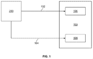
図1は産業施設100の概念図である。産業施設100は、圧縮ガスを使用する施設であり、そうした施設としては、特に限定されないが、食品及び化学処理プラント、統合ガス化複合サイクル発電プラント内部の空気分離ユニット(低温分離型及び膜分離型を含む)、製造プラント、発電プラント内のサイロ燃焼器、高温/高圧抽出装置並びに圧縮ガス生産プラントが含まれる。
FIG. 1 is a conceptual diagram of an
この例示的な実施形態では、産業施設100は、圧縮システム200(以下でより詳細に説明する)に流れ連通状態で結合される。具体的には、システム200は、2つのガス供給導管を介して施設100に流れ連通状態で結合される。より具体的には、施設100とシステム200とは、第1の空気導管102及び第2の空気供給導管104を介して流れ連通状態で結合される。システム200は、第1の圧力での第1の空気ストリーム及び第2の圧力での第2の空気ストリーム(何れも図示せず)を生成し、これら空気ストリームは、それぞれ第1の空気供給導管102及び第2の空気供給導管104を通して送られる。この例示的な実施形態では、第2の圧力は、第1の圧力よりも大きい。それに代えて、システム200は、施設100の運転を容易にする圧力及び流量での任意の数の空気ストリームを生成する。
In this exemplary embodiment,
また、この例示的な実施形態では、施設100は、導管102を介してシステム200に流れ連通状態で結合された第1の圧縮空気受入装置106を含む。さらに、この例示的な実施形態では、施設100は、導管104を介してシステム200に流れ連通状態で結合された第2の圧縮空気受入装置108を含む。様々な実施形態では、装置106及び108は、熱交換器、フィルタ、ストレージタンク、並びに本明細書に記載したように施設100及びシステム200の作動を容易にする他の装置である。
Also in this exemplary embodiment,
図2は、産業施設100で使用することができる例示的な圧縮システム200の概略側面図である。図3は、圧縮システム200の概略俯瞰図である。システム200は、入口フィルタハウジング202を含む。ハウジング202は、所定の粒径及び量の粒子がハウジング202を通過するのを実質的に防止するような適切な濾過レベルの濾過媒体(図示せず)を含む。さらに、濾過媒体は、圧縮システム200を利用する可能性がある特定の加工処理又は産業プラントに合わせて選択される。ハウジング202は、フィルタ入口206を介して大気環境204から空気を引き込む。
FIG. 2 is a schematic side view of an
システム200はまた、フィルタハウジング202に流れ連通状態で結合された過給装置208を含む。装置208は、およそ1.01バール(14.7psia)の大気圧からおよそ1%〜5%だけ空気圧を高める圧力増強装置である。この例示的な実施形態では、装置208は、シャフト205を介して複数の電気モータ駆動装置207及び209に回転可能に結合されかつそれら電気モータ駆動装置207及び209によって駆動される、例えばファン203のような回転装置である。それに代えて、装置208は、単一のモータによって駆動される。また、それに代えて、装置208は、例えば特に限定されないが、ニューヨーク州スケネクタディ所在のGeneral Electric社に譲渡された米国特許第6,530,224号に開示されているように、タービンに回転可能に結合されかつ該タービンによって駆動される。
入口206近傍の空気圧力を高めることは、システム200全体での空気流量を増加させるのを促進する。本明細書に記載するようにシステム200の作動を容易にするため装置208に関連して選択するパラメータには、特に限定されないが、寸法、数、回転速度、圧力上昇及び所要動力が含まれる。この例示的な実施形態では、装置208はハウジング202内に垂直に取付けられて、装置208並びに該装置208のシャフト205に回転可能に結合された駆動装置207及び209に関連するシャフト(図示せず)内に撓み力を生じさせるおそれがある重力が緩和される。さらに、装置208並びにその関連する駆動装置207及び209を垂直方向の配向で取付けることにより、ハウジング202を通して送られる空気流ストリーム(図示せず)に合わせて複数のフェアリング210を使用する更なる利点が得られる。そのようなフェアリング210は、装置208から流出する空気の空気力学的特性の向上を促進にする。それに代えて、装置208は、本明細書に記載したようにシステム200の作動を容易にする配向で取付けられる。
Increasing the air pressure near the
別の実施形態では、特に限定されないが水噴射及び蒸発冷却システムを含む方法を装置208と併せて或いは装置208の代わりに使用して、本明細書に記載したようにシステム200の効率及び有効性の向上を促進する。そのような方法は、例えば特に限定されないが、ニューヨーク州スケネクタディ所在のGeneral Electric社に譲渡された米国特許第6,484,508号に開示されている。さらに別の実施形態では、特に限定されないが、低温システム(chiller system)を含む方法を装置208と併せて或いは装置208の代わりに使用して、本明細書に記載したようにシステム200の効率及び有効性の向上を促進する。そのような方法は、例えば特に限定されないが、ニューヨーク州スケネクタディ所在のGeneral Electric社に譲渡された米国特許第6,058,695号に開示されている。
In another embodiment, methods including, but not limited to, water injection and evaporative cooling systems may be used in conjunction with or in place of
システム200はまた、この例示的な実施形態では、本明細書において主空気圧縮機(M.A.C.)212と呼ばれる第1の圧縮装置を含む。具体的には、M.A.C.212は、GE製の大型高出力ガスタービンエンジンの製品種目の何れかに関連する適切な寸法の圧縮機セクションである低圧軸流圧縮機(LPC)である。そのようなガスタービンエンジンの圧縮機セクションは、特定の空気圧縮システムの要求に合わせて修正することができる。それに代えて、本明細書に記載したようにシステム200の作動を容易にする圧縮装置が使用される。この例示的な実施形態では、システム200はさらに、シャフト216を介してM.A.C.212に回転可能に結合された駆動装置214を含む。具体的には、駆動装置214は、複数の蒸気入口ポート218及び複数の蒸気排出ポート220を有するGE製の複流蒸気タービンである。それに代えて、駆動装置214は、本明細書に記載したようにシステム200の作動を容易にする適切なネームプレート/設計出力のターボ駆動装置である。また、それに代えて、駆動装置214は、本明細書に記載したようにシステム200の作動を容易にする電気モータを始めとする駆動装置である。この例示的な実施形態では、シャフト216は、工場又は作業場でM.A.C.212に対して駆動装置214を結合するために使用する継手(図示せず)を含み、この継手は、第1のベースプレート222(以下でさらに説明する)上に位置合わせしかつ恒久的に及び/又は固定的に取付けることができる。それに代えて、シャフト216は、特に限定されないが固定及び撓み継手を含む、システム200の組立及び作動を容易にする任意のタイプの継手を含む。さらに、それに代えて、駆動装置214は、現場でM.A.C.212に結合され、また現場据付場所で位置合わせされかつ固定取付けされる。
M.A.C.212及び駆動装置214は、第1のモジュラスキッド、プラットホーム又は第1のベースプレート222に対して固定的に結合されるか又は取付けられる。第1のベースプレート222は、現場への輸送に先立つ工場又は作業場内でのプレハブ組立を容易にすることによって、システム200の少なくとも一部分のモジュール式組立を容易にする。第1のベースプレート222はまた、特に限定されないがM.A.C.212及び駆動装置214を含む設備の寸法及び重量の制限を少なくとも部分的に定めることによって、工場又は作業場から現場にシステム200の少なくとも一部分を輸送するのに役立つ。さらに、第1のベースプレート222は、M.A.C.212及び駆動装置214に関連する設備移動の回数を減少させることによって、輸送を容易にする。設備の寸法及び重量を制限しかつ設備移動の回数を軽減することは各々、輸送及び据付けコストの低減に資する。この例示的な実施形態では、M.A.C.212及び駆動装置214は、現場検査及び保守作業を容易にするため、第1のベースプレート222上に配向される。第1のベースプレート222は、該第1のベースプレート222に固定結合された複数の吊り金具224を含む。吊り金具224は、第1のベースプレート222に固定されたM.A.C.212及び駆動装置214を含む構成要素と共に第1のベースプレート222の移動を容易にするような寸法及び配向にされる。
M.M. A. C. 212 and drive 214 are fixedly coupled or attached to the first modular skid, platform or
駆動装置214は、各端部で設備を駆動するように構成される。この構成は、本明細書に記載したシステム200の圧縮設備の水平取付けを容易にする。そのような水平取付けでは、垂直支持構造体を必要としないので、システム200を収容する関連の建物或いは垂直構造物に関連する設備調達及び建設コストが低減される。この構成はまた、駆動装置214を使用して、小型かつ軽量の圧縮装置の使用を容易にするに十分なほど高い速度で結合空気圧縮装置を駆動するのを促進する。
The
この例示的な実施形態では、駆動装置214は、固定継手(図示せず)を含むシャフト228を介してギアボックス226に結合される。それに代えて、シャフト228は、本明細書に記載したようにシステム200の作動を容易にする寸法及び設計の継手を含む。また、この例示的な実施形態では、ギアボックス226は、複数のセットアップギア(図示せず)を含む。ギアボックス226は、シャフト228によって誘導された回転入力速度を受け、ギアボックス出力シャフト230の回転出力速度が入力速度よりも高くなるようにその速度を増大させる。ギアボックス226は、第1のベースプレート222に固定される。
In the exemplary embodiment, drive 214 is coupled to
ギアボックス226は、シャフト230を介して中間空気圧縮機(I.A.C.)232に回転可能に結合される。この例示的な実施形態では、I.A.C.232は、GE製のNuovo Pignone2段遠心空気圧縮機である。それに代えて、I.A.C.232は、本明細書に記載したようにシステム200の作動を容易にする寸法及び構成の圧縮機である。同様に、この例示的な実施形態では、I.A.C.232は、シャフト236を介してブースト空気圧縮機(B.A.C.)234に結合される。それに代えて、ギアボックス226は、I.A.C.232とB.A.C.234との間に取付けて、I.A.C.232の回転速度の範囲が蒸気タービンエンジン駆動装置214の回転速度範囲と実質的に同じになるようにする。この例示的な実施形態では、B.A.C.234は、GE製のNuovo Pignone6段遠心空気圧縮機である。それに代えて、B.A.C.234は、本明細書に記載したようにシステム200の作動を容易にする寸法及び構成の圧縮機である。また、この例示的な実施形態では、シャフト230は、撓み継手237を含む。さらに、この例示的な実施形態では、シャフト236は、撓み継手(図示せず)を含む。それに代えて、シャフト230及び236は、本明細書に記載するようにシステム200の作動を容易にする継手を含む。
この例示的な実施形態では、I.A.C.232及びB.A.C.234は、互いに回転可能に結合され、かつ工場又は作業場で第2のモジュラスキッド、プラットホーム又はベースプレート238に固定される。第2のベースプレートは、複数の吊り金具240を含む。さらに、ベースプレート238は、第1のベースプレート222と同様な利点を有する。さらに、第1のベースプレート222及びベースプレート238は、撓み継手237を介してギアボックス226及びI.A.C.232間の単一の回転可能現場結合及び位置合わせを容易にする配向にされ、それによって据付時間及びコストの低減を促進する。プラットホーム222及び238は、振動又は他の原因によるシステム200内部のミスアラインメントを緩和するために、互いに固定結合される。この例示的な実施形態で示すような設備の配向、すなわち、第1のモジュラベースプレート222へのM.A.C.212、駆動装置214及びギアボックス226の固定結合並びに第2のモジュラベースプレート238へのI.A.C.232及びB.A.C.234の固定結合は、別の実施形態では必要に応じて、設備重量、寸法及び他の位置合わせパラメータに資するように調整することができる。
In this exemplary embodiment, I.I. A. C. 232 and B.I. A. C. 234 are rotatably coupled to each other and secured to a second modular skid, platform or
M.A.C.212は、装置208に流れ連通状態で結合された入口部分242を含み、部分242は、装置208による僅かな圧力上昇のために基準大気圧よりも幾らか高い圧力で空気を受入れる。M.A.C.212はまた、部分242に流れ連通状態で結合された複数の段244を含み、これら複数の段244は、ボリュート246と協働して高圧のM.A.C.吐出空気ストリーム(図示せず)の形成を促進する。システム200は、導管250及び第1のサージ防止装置252を介してボリュート246に流れ連通状態で結合された熱交換器248を含む。この例示的な実施形態では、熱交換器248は、I.A.C.232内への流入に先立って圧縮空気ストリームの温度を所定の範囲に低下させるような寸法のチューブ−シェル型熱交換器である。また、この例示的な実施形態では、装置252は、可変ブリードバルブである。それに代えて、熱交換器248及び装置252は、それぞれ本明細書に記載したようにシステム200の作動を促進する熱交換器及びサージ防止装置のモデルである。
M.M. A. C. 212 includes an
熱交換器248は、圧縮空気温度を、該熱交換器248から流出するときに示す通常のレベルまで低下させるのを可能にし、従って次の圧縮セクション、すなわちI.A.C.232において必要となる所要動力(動力要件)の低減を促進する。別の実施形態では、熱交換器248から取出された熱は、圧縮システム200を使用する施設の作動に取入れられ、そのような作動としては、特に限定されないが、蒸気の生成或いはその他の加熱を必要とするものが挙げられる。
The
熱交換器248は、導管254を介してI.A.C.232に流れ連通状態で結合される。導管254は、冷却済み空気ストリーム(図示せず)をI.A.C.入口部分258に送る。I.A.C.232は、加圧空気ストリーム(図示せず)を形成し、かつそのストリームをI.A.C.出口部分260を介して導管258内に吐出する。幾つかの実施形態では、出口部分260の下流に二次熱交換器261が配置される。熱交換器261は、加圧空気ストリームを冷却するのを可能にして、B.A.C.234の駆動に関連する設計所要動力の低減を促進し、かつ/又は特に限定されないが空気受入装置106を含む導管102の下流の構成要素によって定まる温度範囲内での作動を促進する。
システム200はまた、導管258を介してI.A.C.出口部分260に流れ連通状態で結合された三方流量制御バルブ262を含み、バルブ262は、I.A.C.232から吐出された空気ストリームを2つの空気ストリームに分割するように構成される。第1の空気供給導管102は、バルブ262に流れ連通状態で結合され、かつ第1の空気ストリーム(図示せず)を第1の所定の空気圧力で産業施設100内の第1の空気受入装置106に送るように構成される。この例示的な実施形態では、第1の空気圧力は、特に限定されないが空気分離ユニット及び加圧空気ストレージの部分を含む低圧用途に適合するように選択される。
システム200はさらに、導管264と第1のサージ防止装置252に実質的に類似した第2のサージ防止装置266とを含む。装置252及び266は、配管破損又は機器損傷につながる可能性がある作動過渡状態によるシステム200内の過大昇圧及び圧縮機サージを協働して緩和するように配置されかつ構成される。具体的には、第1の装置252は、I.A.C.232までのM.A.C.212の下流の空気のボリュームに併せてM.A.C.212の上流の加圧空気の実質的に全ボリュームの放出を容易にするほど十分にM.A.C.212に接近させて配向される。第2の装置266は、導管258内部で二次熱交換器261と出口部分260との間に配向されて、I.A.C.232と装置266との間のシステム200内部の加圧空気の実質的に全ボリューム並びに装置266の下流の加圧空気の実質的に全ボリュームの放出を容易にする。
The
B.A.C.中間及び最終冷却熱交換器276は、導管264を介してバルブ262に流れ連通状態で結合される。熱交換器276は、I.A.C.232からの加圧空気ストリームの少なくとも一部分を受入れ、その空気ストリームから少なくとも幾らかの熱を除去し、かつ冷却済み空気ストリーム267をB.A.C.234に吐出する。
B. A. C. Intermediate and final
B.A.C.234は、熱交換器276に流れ連通状態で結合されかつ冷却済み空気ストリーム267を受入れる入口部分268を含む。B.A.C.234はまた、第1の圧縮セクション270を含み、第1の圧縮セクション270は、B.A.C.234内の6段のうちの最初の3つを含む。セクション270は、部分268及び中間抽気部分272に流れ連通状態で結合され、空気ストリーム274をB.A.C.中間及び最終冷却熱交換器276に吐出する。熱交換器276は、部分272及び第2の圧縮セクション吸引部分278に流れ連通状態で結合される。熱交換器276は、空気ストリーム274を受入れ、空気ストリーム274から少なくとも幾らかの熱を除去し、かつ冷却済み空気ストリーム280を吸引部分278に吐出する。吸引部分278は、B.A.C.234の最終の3段を含む第2の圧縮部分282に流れ連通状態で結合され、これら最終の3段は次に、最終吐出部分284に流れ連通状態で結合される。部分284は、熱交換器276に流れ連通状態で結合される。部分284は、最終冷却のため熱交換器276に送られる空気ストリーム286を形成する。熱交換器276は、第2の空気供給導管104に流れ連通状態で結合され、第2の空気ストリーム(図示せず)を産業施設100内の第2の空気受入装置108に送る。
B. A. C. 234 includes an
流体圧縮システム200を組立てる例示的な方法は、第1のモジュラベースプレート222に対して1以上の第1の圧縮装置、すなわちM.A.C.212を固定結合する段階を含む。本方法はまた、第1のモジュラベースプレート及び第2のモジュラベースプレート238の1つに対して1以上の駆動装置、すなわち駆動装置214を固定結合する段階を含む。本方法はさらに、第2のモジュラベースプレート238に対して結第1のモジュラベースプレート222を合する段階をさらに含む。
An exemplary method for assembling the
作動において、ハウジング202は、フィルタ入口26を介して大気環境204から空気を引き込む。装置208は、およそ1.01バール(14.7psia)の大気圧からおよそ1%〜5%だけ空気圧を高める。フェアリング210は、装置208を流出する空気の空気力学的特性を向上させるのを可能にする。
In operation, the
駆動装置214は、入口ポート218を介して蒸気を受入れ、当技術分野では公知のように蒸気からエネルギーを取り出し、かつポート212を通してエネルギー低下蒸気を排出する。駆動装置214は、シャフト216を回転可能に駆動し、シャフト216が次に、M.A.C.212を回転可能に駆動する。駆動装置214はまた、シャフト228を介してギアボックス226を回転可能に駆動する。ギアボックス226は、シャフト228によって誘導された回転入力速度を受け、ギアボックス出力シャフト230の回転出力速度が入力速度よりも高くなるようにその速度を増大させる。ギアボックス226は次に、シャフト230及び撓み継手を介してI.A.C.232を回転可能に駆動し、かつシャフト236を介してB.A.C.234を駆動する。
The
M.A.C.212のM.A.C.212入口部分242は、装置208から空気を受入れる。入口部分242は複数の段244に空気を流し、これら複数の段244は、出口ボリュート246と協働してM.A.C.吐出空気ストリームを形成するのを可能にする。空気ストリームは、導管250及び第1のサージ防止装置252を介して熱交換器248に送られる。
M.M. A. C. 212 M.M. A. C. The 212
熱交換器248は、空気ストリームから熱を除去し、導管254は、I.A.C.入口部分256に冷却済み空気ストリームを送る。I.A.C.232は、冷却済み空気ストリームを受入れ、かつ加圧空気ストリームを形成する。加圧ストリームは、I.A.C.出口部分260を介して導管258内に吐出される。
The
加圧ストリームは、導管258、熱交換器261及び装置266を介してバルブ262に送られる。熱交換器261は、導管258内を流れる空気ストリームから少なくとも幾らかの熱を除去する。バルブ262は、I.A.C.232から吐出された空気ストリームを2つの空気ストリームに分割する。第1の空気ストリームは、第1の空気供給導管102に送られ、第1の空気供給導管102は次に、第1の空気ストリームを産業施設100内の第1の空気受入装置106に送る。別の空気ストリームは、導管264を介して熱交換器276に送られる。
The pressurized stream is sent to
入口部分268は、熱交換器276から冷却済み空気ストリーム267を受入れかつその空気を第1の圧縮セクション270に送り、第1の圧縮セクション270は、空気を部分的に圧縮しかつその空気を中間抽気部分272に送り、中間抽気部分272は、空気ストリーム274をB.A.C.中間及び最終冷却熱交換器276に吐出する。熱交換器276は、空気ストリーム274を受入れ、空気ストリーム274から少なくとも幾らかの熱を除去し、かつ冷却済み空気ストリーム280を吸引部分278に吐出する。吸引部278は、空気を第2の圧縮部分282に送り、第2の圧縮部分282は、その空気を圧縮しかつその空気を最終吐出部分284に送る。部分284は、最終冷却のために熱交換器276に送られる空気ストリーム286を形成する。熱交換器276は、ストリーム286から熱を除去しかつストリーム286を第2の空気供給導管104に送り、第2の空気供給導管104は次に、第2の空気ストリームを産業施設100内の第2の空気受入装置108に送る。
The
本明細書に記載したようにガスを圧縮するための方法及び装置は、空気圧縮システムを含む生産施設の作動を促進する。具体的には、本明細書に記載した空気圧縮システムは、産業施設の作動を促進する。より具体的には、モジュラプラットホームは、現場への輸送に先立つ工場又は作業場内でのプレハブ組立を容易にすることによって、空気圧縮システムの組立を容易にする。モジュラプラットホームはまた、プラットホームに固定される設備の寸法及び重量の制限を少なくとも部分的に定めることによって、工場又は作業場から現場にシステムの少なくとも一部分の輸送を容易にする。さらに、プラットホームは、該プラットホームに固定される設備に関連する設備移動の回数を減少させることによって、輸送を容易にする。設備の寸法及び重量を制限しかつ設備移動の回数を軽減することは、輸送及び据付けコストの低減を促進する。また、設備は、現場検査及び保守作業を容易にするように、プラットホーム上に配向することができる。さらに、プラットホームは、2つのモジュラプラットホームの間の単一の回転可能現場結合及び位置合わせを容易にする配向にされ、それによって据付時間及びコストの低減に資する。また、この構成は、システムの圧縮装置の水平取付けを容易にし、それによってシステムを収容する関連の垂直構造物に関連する設備調達及び建設コストを低減する。さらに、高速の駆動装置が圧縮装置の全てを回転可能に駆動するようにした設備の配置は、圧縮装置の寸法及び重量の低減を促進する。 A method and apparatus for compressing gas as described herein facilitates operation of a production facility that includes an air compression system. Specifically, the air compression system described herein facilitates the operation of industrial facilities. More specifically, the modular platform facilitates assembly of the air compression system by facilitating prefabrication in a factory or workshop prior to on-site transportation. The modular platform also facilitates transportation of at least a portion of the system from the factory or workplace to the field by at least partially defining the size and weight limitations of the equipment secured to the platform. In addition, the platform facilitates transportation by reducing the number of equipment movements associated with equipment secured to the platform. Limiting the size and weight of the equipment and reducing the number of equipment moves facilitates a reduction in transportation and installation costs. Also, the equipment can be oriented on the platform to facilitate field inspection and maintenance operations. In addition, the platform is oriented to facilitate a single rotatable field connection and alignment between the two modular platforms, thereby reducing installation time and cost. This configuration also facilitates horizontal mounting of the system's compression device, thereby reducing equipment procurement and construction costs associated with the associated vertical structure that houses the system. In addition, the arrangement of equipment such that the high speed drive device drives all of the compression device in a rotatable manner facilitates reducing the size and weight of the compression device.
以上、産業施設に関連する空気圧縮の例示的な実施形態を詳細に説明している。本方法、装置及びシステムは、本明細書に記載した特定の実施形態に限定されるものではないし、また特定の例示した空気圧縮システム及び産業施設にも限定されるものではない。 The foregoing has described in detail an exemplary embodiment of air compression associated with an industrial facility. The methods, apparatus, and systems are not limited to the specific embodiments described herein, and are not limited to the specific illustrated air compression systems and industrial facilities.
様々な特定の実施形態に関して本発明を説明してきたが、本発明が特許請求の範囲の技術思想及び技術的範囲内の変更で実施することができることは、当業者は明らかであろう。 While the invention has been described in terms of various specific embodiments, those skilled in the art will recognize that the invention can be practiced with modification within the spirit and scope of the claims.
100 産業施設
102 第1の空気供給導管
104 第2の空気供給導管
106 第1の空気受入装置
108 第2の空気受入装置
200 ハウジングシステム
202 ハウジング
203 ファン
204 大気環境
205 シャフト
206 フィルタ入口
207 電気モータ駆動装置
208 取付け装置又は過給装置
209 電気モータ駆動装置
210 フェアリング
212 (M.A.C.)主空気圧縮機又は第1の圧縮装置
214 駆動装置
216 シャフト
218 蒸気入口ポート
220 蒸気排出ポート
222 第1のベースプレート又はプラットホーム
224 吊り金具
226 ギアボックス
228 シャフト
230 ギアボックス出力シャフト
232 (I.A.C.)中間空気圧縮機又は第2の圧縮装置
234 (B.A.C.)ブースト空気圧縮機
236 シャフト
237 撓み継手
238 第2のモジュラベースプレート又はプラットホーム
240 吊り金具
242 入口部分
244 段
246 出口ボリュート
248 熱交換器
250 導管
252 サージ防止装置
254 導管
256 入口部分
258 導管
260 出口部分
261 熱交換器
262 流量制御バルブ
264 導管
266 サージ防止装置
267 冷却空気ストリーム
268 入口部分
270 第1の圧縮セクション
272 中間抽気部分
274 空気ストリーム
276 熱交換器
278 吸引部分
280 冷却空気ストリーム
282 第2の圧縮部分
284 最終吐出部分
286 空気ストリーム
DESCRIPTION OF
Claims (10)
前記入口フィルタハウジングの実質的に内部に位置するように、前記入口フィルタハウジングに結合された1以上の過給装置と、
実質的に平らな第1のプラットホームに取り付けられた1以上の第1の圧縮装置と、
前記第1のプラットホームに結合され実質的に平らな別個の第2のプラットホームに取り付けられ、第2の圧縮装置を含む1以上の別個の第2の圧縮構成要素と、
を含み、
前記1以上の第2の圧縮装置が、前記1以上の第1の圧縮装置に直列流れ連通状態で結合され、
前記1以上の過給装置が、前記1以上の第1の圧縮装置および前記1以上の第2の圧縮装置に直列流れ連通状態で結合される、
モジュール式圧縮システム。 An inlet filter housing;
One or more supercharging devices coupled to the inlet filter housing so as to be substantially internal to the inlet filter housing;
One or more first compression devices attached to a substantially flat first platform;
One or more separate second compression components coupled to the first platform and attached to a substantially flat separate second platform, including a second compression device;
Including
The one or more second compression devices are coupled to the one or more first compression devices in serial flow communication;
The one or more supercharging devices are coupled in series flow communication with the one or more first compression devices and the one or more second compression devices;
Modular compression system.
前記第2のプラットホームに結合されかつ前記1以上の第2の圧縮装置と該1以上の第2の圧縮装置に回転可能に結合された1以上の第2のシャフトとを備えた該モジュール式圧縮システムの第2の部分と、
を含み、
前記1以上の第2のシャフトが、前記1以上の第1のシャフトに回転可能に結合される、
請求項5に記載のモジュール式圧縮システム。 The modular compression coupled to the first platform and comprising one or more first compression devices and one or more first shafts rotatably coupled to the one or more first compression devices. A first part of the system;
The modular compression comprising the one or more second compression devices coupled to the second platform and one or more second shafts rotatably coupled to the one or more second compression devices. A second part of the system;
Including
The one or more second shafts are rotatably coupled to the one or more first shafts;
The modular compression system according to claim 5.
The modular compression system of claim 9, wherein the one or more second compression devices are coupled to the one or more third compression devices in series flow communication.
Applications Claiming Priority (2)
| Application Number | Priority Date | Filing Date | Title |
|---|---|---|---|
| US11/742,195 | 2007-04-30 | ||
| US11/742,195 US8047809B2 (en) | 2007-04-30 | 2007-04-30 | Modular air compression apparatus with separate platform arrangement |
Publications (3)
| Publication Number | Publication Date |
|---|---|
| JP2008274947A JP2008274947A (en) | 2008-11-13 |
| JP2008274947A5 JP2008274947A5 (en) | 2013-01-24 |
| JP5271596B2 true JP5271596B2 (en) | 2013-08-21 |
Family
ID=39591388
Family Applications (1)
| Application Number | Title | Priority Date | Filing Date |
|---|---|---|---|
| JP2008116512A Expired - Fee Related JP5271596B2 (en) | 2007-04-30 | 2008-04-28 | Method and apparatus for promoting gas compression |
Country Status (4)
| Country | Link |
|---|---|
| US (1) | US8047809B2 (en) |
| EP (1) | EP1988291A3 (en) |
| JP (1) | JP5271596B2 (en) |
| KR (1) | KR101385836B1 (en) |
Families Citing this family (10)
| Publication number | Priority date | Publication date | Assignee | Title |
|---|---|---|---|---|
| FR2943772A1 (en) * | 2009-03-27 | 2010-10-01 | Air Liquide | APPARATUS AND METHOD FOR AIR SEPARATION BY CRYOGENIC DISTILLATION |
| ITCO20120002A1 (en) * | 2012-01-27 | 2013-07-28 | Nuovo Pignone Srl | COMPRESSOR SYSTEM FOR NATURAL GAS, METHOD FOR COMPRESSING NATURAL GAS AND PLANT THAT USES THEM |
| US20130251555A1 (en) * | 2012-03-26 | 2013-09-26 | Pedro Ismael DePAZ | Power system arrangement |
| US9388709B2 (en) * | 2014-08-15 | 2016-07-12 | Siemens Energy, Inc. | Gas turbine rotor and exhaust maintenance skid |
| CN106574626A (en) * | 2014-09-18 | 2017-04-19 | 三菱重工压缩机有限公司 | Compressor system |
| DE102015204466A1 (en) * | 2015-03-12 | 2016-09-15 | Siemens Aktiengesellschaft | Two-compressor arrangement, retrofit procedure |
| US9376801B1 (en) | 2015-04-17 | 2016-06-28 | Solar Turbines Incorporated | Modular deployment of gas compression facilities |
| US9777882B2 (en) | 2015-12-03 | 2017-10-03 | Ingersoll-Rand Company | Skeleton base for a compressor system |
| IT201700100704A1 (en) * | 2017-09-08 | 2019-03-08 | Nuovo Pignone Tecnologie Srl | CONTROL SYSTEM FOR A COMPRESSOR WITH A PRESSURE-BASED SUBSYSTEM, SYNTHESIS SYSTEM AND CONTROL SYSTEM / CONTROL SYSTEM FOR A COMPRESSOR WITH PRESSURE-BASED SUBSYSTEM, SYNTHESIS PLANT AND CONTROL METHOD |
| IT201700100734A1 (en) * | 2017-09-08 | 2019-03-08 | Nuovo Pignone Tecnologie Srl | CONTROL SYSTEM FOR A COMPRESSOR WITH SPEED BASED SUBSYSTEM, SYNTHESIS SYSTEM AND CONTROL SYSTEM / CONTROL SYSTEM FOR A COMPRESSOR WITH SPEED-BASED SUBSYSTEM, SYNTHESIS PLANT AND CONTROL METHOD |
Family Cites Families (33)
| Publication number | Priority date | Publication date | Assignee | Title |
|---|---|---|---|---|
| US1418202A (en) * | 1921-05-20 | 1922-05-30 | Ingersoll Rand Co | Vertical compressor unit |
| US1898729A (en) * | 1925-11-06 | 1933-02-21 | Huguenin Albert | Device for the cooling of compressors with pistons |
| US2256654A (en) * | 1937-02-01 | 1941-09-23 | Sears Roebuck & Co | Twin compressor unit |
| US2227532A (en) * | 1939-07-31 | 1941-01-07 | Jr Channing M Cave | Automatic control means |
| US2458284A (en) * | 1945-02-16 | 1949-01-04 | Ingersoll Rand Co | Cooling-water supply apparatus for compressors |
| US2954918A (en) * | 1958-07-03 | 1960-10-04 | Ajax Iron Works | Combination engine and compressor unit |
| BE685727A (en) * | 1965-08-23 | 1967-02-01 | ||
| US3736074A (en) * | 1972-04-20 | 1973-05-29 | Worthington Cei | Inlet, filter and noise suppressor enclosure for compressing apparatus |
| US4097202A (en) * | 1976-06-21 | 1978-06-27 | Billy Frank Price | Auxiliary compressor assembly |
| US4693669A (en) | 1985-03-29 | 1987-09-15 | Rogers Sr Leroy K | Supercharger for automobile engines |
| US4638971A (en) * | 1986-02-04 | 1987-01-27 | Dowell Schlumberger Incorporated | Machinery skid |
| US5282726A (en) * | 1991-06-21 | 1994-02-01 | Praxair Technology, Inc. | Compressor supercharger with evaporative cooler |
| US5626468A (en) * | 1995-05-09 | 1997-05-06 | Enterra Compression Company | Skid for compressor |
| BE1010122A3 (en) * | 1996-03-19 | 1998-01-06 | Atlas Copco Airpower Nv | COMPRESSOR DEVICE. |
| JP3425308B2 (en) * | 1996-09-17 | 2003-07-14 | 株式会社 日立インダストリイズ | Multistage compressor |
| GB9801200D0 (en) | 1998-01-20 | 1998-03-18 | Air Prod & Chem | Intergration of a cryogenic air separator with synthesis gas production and conversion |
| US6058695A (en) | 1998-04-20 | 2000-05-09 | General Electric Co. | Gas turbine inlet air cooling method for combined cycle power plants |
| US6484508B2 (en) | 1998-07-24 | 2002-11-26 | General Electric Company | Methods for operating gas turbine engines |
| US6328024B1 (en) | 1999-03-30 | 2001-12-11 | Mark S. Kibort | Axial flow electric supercharger |
| US6308512B1 (en) | 1999-06-10 | 2001-10-30 | Enhanced Turbine Output Holding, Llc | Supercharging system for gas turbines |
| US7065953B1 (en) | 1999-06-10 | 2006-06-27 | Enhanced Turbine Output Holding | Supercharging system for gas turbines |
| EP1074746B1 (en) * | 1999-07-16 | 2005-05-18 | Man Turbo Ag | Turbo compressor |
| DE10054152C1 (en) * | 2000-11-02 | 2002-03-28 | Knorr Bremse Systeme | Air compressor management method for rail vehicle has different compressors switched into operation in fixed or variable priority sequence |
| US6360731B1 (en) * | 2000-11-27 | 2002-03-26 | Yung-Yu Chang | Axial-type supercharger |
| US6530224B1 (en) | 2001-03-28 | 2003-03-11 | General Electric Company | Gas turbine compressor inlet pressurization system and method for power augmentation |
| US6880343B2 (en) | 2001-12-06 | 2005-04-19 | William L. Kopko | Supercharged gas turbine with improved control |
| US6672062B2 (en) | 2001-12-21 | 2004-01-06 | Caterpillar Inc | Multi-stage supercharger arrangement with cross flow |
| DE10329281A1 (en) | 2003-06-30 | 2005-01-20 | Daimlerchrysler Ag | Compressor in the intake of an internal combustion engine |
| US6938404B2 (en) | 2003-09-23 | 2005-09-06 | Rrc-Sgte Technologies, Llc | Supercharged open cycle gas turbine engine |
| US20060177302A1 (en) | 2005-02-04 | 2006-08-10 | Berry Henry M | Axial flow compressor |
| EP1764542A1 (en) * | 2005-09-19 | 2007-03-21 | Siemens Aktiengesellschaft | Industrial equipment chassis |
| CN101268281A (en) * | 2005-09-19 | 2008-09-17 | 英格索尔-兰德公司 | Multi-stage compression system including variable speed motors |
| US8376718B2 (en) * | 2009-06-24 | 2013-02-19 | Praxair Technology, Inc. | Multistage compressor installation |
-
2007
- 2007-04-30 US US11/742,195 patent/US8047809B2/en not_active Expired - Fee Related
-
2008
- 2008-04-23 EP EP08154980.0A patent/EP1988291A3/en not_active Withdrawn
- 2008-04-28 JP JP2008116512A patent/JP5271596B2/en not_active Expired - Fee Related
- 2008-04-29 KR KR1020080039709A patent/KR101385836B1/en not_active IP Right Cessation
Also Published As
| Publication number | Publication date |
|---|---|
| US20080264061A1 (en) | 2008-10-30 |
| JP2008274947A (en) | 2008-11-13 |
| KR20080097136A (en) | 2008-11-04 |
| EP1988291A3 (en) | 2017-06-28 |
| EP1988291A2 (en) | 2008-11-05 |
| KR101385836B1 (en) | 2014-04-16 |
| US8047809B2 (en) | 2011-11-01 |
Similar Documents
| Publication | Publication Date | Title |
|---|---|---|
| JP5271596B2 (en) | Method and apparatus for promoting gas compression | |
| US10704472B2 (en) | Mobile power generation system including air filtration | |
| CN204610202U (en) | For compressed-air actuated system | |
| CN105222980B (en) | A kind of wind tunnel body pumped vacuum systems | |
| JP5863320B2 (en) | Centrifugal compressor | |
| US10458334B2 (en) | Mobile power generation system including closed cell base structure | |
| JP5631660B2 (en) | Turbine system | |
| JP6263170B2 (en) | Combination of two gas turbines to drive a load | |
| JP2003529701A (en) | Supercharged gas turbine device, supercharged auxiliary device, supercharged gas turbine device operating method, high-pressure fluid transfer duct, and power generation facility | |
| CN203201825U (en) | Compressor arrangement | |
| US20120171052A1 (en) | Motor compressor system and method | |
| EP3080405B1 (en) | Gas turbine offshore installations | |
| CN102748121A (en) | Two-stage turbocharger for aviation piston engine | |
| RU2554670C1 (en) | Two-shaft gas-compressor unit for booster compressor stations | |
| CA2433636A1 (en) | Installation for the generation of energy | |
| KR20110082356A (en) | Centrifugal compressor and fabricating method thereof | |
| RU2463515C1 (en) | Modular compressor station | |
| CN111426484A (en) | Air source system of test bed of aero-engine combustion chamber | |
| RU64712U1 (en) | MOBILE COMPRESSOR STATION | |
| KR101578027B1 (en) | Compressor and energy saving system using the same | |
| Smirnov et al. | The results of pre-design studies on the development of a new design of gas turbine compressor package of GPA-C-16 type | |
| CN116428058A (en) | Hidden air inlet system of marine miniature gas turbine | |
| JP6049807B2 (en) | Centrifugal compressor | |
| RU46541U1 (en) | ELECTRIC POWER GAS-TURBO-EXPANDER INSTALLATION | |
| RU2334887C1 (en) | Heat-recovery cooled gas turbine power plant |
Legal Events
| Date | Code | Title | Description |
|---|---|---|---|
| RD04 | Notification of resignation of power of attorney |
Free format text: JAPANESE INTERMEDIATE CODE: A7424 Effective date: 20110125 |
|
| A621 | Written request for application examination |
Free format text: JAPANESE INTERMEDIATE CODE: A621 Effective date: 20110418 |
|
| A521 | Request for written amendment filed |
Free format text: JAPANESE INTERMEDIATE CODE: A523 Effective date: 20120416 |
|
| A521 | Request for written amendment filed |
Free format text: JAPANESE INTERMEDIATE CODE: A523 Effective date: 20121130 |
|
| A131 | Notification of reasons for refusal |
Free format text: JAPANESE INTERMEDIATE CODE: A131 Effective date: 20121218 |
|
| A521 | Request for written amendment filed |
Free format text: JAPANESE INTERMEDIATE CODE: A523 Effective date: 20130315 |
|
| TRDD | Decision of grant or rejection written | ||
| A01 | Written decision to grant a patent or to grant a registration (utility model) |
Free format text: JAPANESE INTERMEDIATE CODE: A01 Effective date: 20130416 |
|
| A61 | First payment of annual fees (during grant procedure) |
Free format text: JAPANESE INTERMEDIATE CODE: A61 Effective date: 20130513 |
|
| R150 | Certificate of patent or registration of utility model |
Free format text: JAPANESE INTERMEDIATE CODE: R150 |
|
| R250 | Receipt of annual fees |
Free format text: JAPANESE INTERMEDIATE CODE: R250 |
|
| LAPS | Cancellation because of no payment of annual fees |