JP5269007B2 - Engine equipment - Google Patents

Engine equipment Download PDF

Info

Publication number
JP5269007B2
JP5269007B2 JP2010163174A JP2010163174A JP5269007B2 JP 5269007 B2 JP5269007 B2 JP 5269007B2 JP 2010163174 A JP2010163174 A JP 2010163174A JP 2010163174 A JP2010163174 A JP 2010163174A JP 5269007 B2 JP5269007 B2 JP 5269007B2
Authority
JP
Japan
Prior art keywords
exhaust gas
filter
catalyst
outer case
case
Prior art date
Legal status (The legal status is an assumption and is not a legal conclusion. Google has not performed a legal analysis and makes no representation as to the accuracy of the status listed.)
Active
Application number
JP2010163174A
Other languages
Japanese (ja)
Other versions
JP2010285994A5 (en
JP2010285994A (en
Inventor
匡孝 光田
Current Assignee (The listed assignees may be inaccurate. Google has not performed a legal analysis and makes no representation or warranty as to the accuracy of the list.)
Yanmar Co Ltd
Original Assignee
Yanmar Co Ltd
Priority date (The priority date is an assumption and is not a legal conclusion. Google has not performed a legal analysis and makes no representation as to the accuracy of the date listed.)
Filing date
Publication date
Application filed by Yanmar Co Ltd filed Critical Yanmar Co Ltd
Priority to JP2010163174A priority Critical patent/JP5269007B2/en
Publication of JP2010285994A publication Critical patent/JP2010285994A/en
Publication of JP2010285994A5 publication Critical patent/JP2010285994A5/ja
Application granted granted Critical
Publication of JP5269007B2 publication Critical patent/JP5269007B2/en
Active legal-status Critical Current
Anticipated expiration legal-status Critical

Links

Images

Abstract

<P>PROBLEM TO BE SOLVED: To provide an exhaust gas control device arranging connection sections of a plurality of outer cases by offsetting them against joining sections of a plurality of gas purification filters, simply reducing mounting intervals of the plurality of gas purification filters, and forming an outside dimension in an exhaust gas moving direction in a compact size. <P>SOLUTION: The exhaust gas control device has a structure having: a plurality of gas purification filters 2, 3 for purifying exhaust gas discharged by an engine; inner cases 4, 20 internally arranged the gas purification filters 2, 3; and the plurality of outer cases 5, 21 for internally arranging the inner cases 4, 20. The length of the inner cases 4, 20 in the moving direction of the exhaust gas and the length of the outer cases 5, 21 in the moving direction of the exhaust gas are different from each other. <P>COPYRIGHT: (C)2011,JPO&amp;INPIT

Description

本発明は、排気ガス中に含まれた粒子状物質(すす、パティキュレート)、又はNOx(窒素酸化物)等を除去する排気ガス浄化装置を搭載するエンジン装置に関するものである。 The present invention includes the particulate matter in the exhaust gas (soot, particulate) or NOx (nitrogen oxides) and the like relates to an engine device for mounting the exhaust gas purifying apparatus for removing.

従来、ディーゼルエンジン等に適用される排気ガス浄化装置において、走行機体等に搭載されるディーゼルエンジンの排気ガス排出径路中に、ディーゼルパティキュレートフィルタ(又はNOx触媒)等が設けられ、ディーゼルエンジンから排出された排気ガスが、ディーゼルパティキュレートフィルタ(又はNOx触媒)等によって浄化処理されるようにした技術がある(特許文献1、特許文献2、特許文献3)。また、ケーシング(管体)内にフィルタケース(内側ケース)を設け、フィルタケース内にパティキュレートフィルタを配置する技術も公知である(特許文献4参照)。   Conventionally, in an exhaust gas purification device applied to a diesel engine or the like, a diesel particulate filter (or NOx catalyst) or the like is provided in an exhaust gas discharge path of a diesel engine mounted on a traveling machine body or the like, and exhausted from the diesel engine. There is a technique in which the exhaust gas thus purified is purified by a diesel particulate filter (or NOx catalyst) or the like (Patent Document 1, Patent Document 2, and Patent Document 3). Further, a technique in which a filter case (inner case) is provided in a casing (tubular body) and a particulate filter is disposed in the filter case is also known (see Patent Document 4).

特開2000−145430号公報JP 2000-145430 A 特開2003−27922号公報Japanese Patent Laid-Open No. 2003-27922 特開2008−82201号公報JP 2008-82201 A 特開2001−173429号公報JP 2001-173429 A

パティキュレートフィルタを内設したフィルタケースに、ガス入口管(入口構成部品)及び支持脚体を設ける構造において、ディーゼルエンジンにフィルタケースを直接搭載した場合、ディーゼルエンジンからの振動や応力(変形力)がフィルタケースに付加される。即ち、ディーゼルエンジンからの振動や応力によって、パティキュレートフィルタ(フィルタに被覆した保持マット等)や、支持脚体が変形損傷しやすい等の問題がある。また、支持脚体の溶接によるフィルタケースの歪等によって、パティキュレートフィルタや、支持脚体の接合部が変形損傷しやすい等の問題がある。さらに、ガス浄化フィルタをそれぞれ内設した複数のフィルタケース(内側ケース)と、各フィルタケースをそれぞれ内設した複数の外側ケースを備える構造において、各外側ケースをフランジによって分離可能に連結した場合、各ガス浄化フィルタの合わせ面(接合面)にフランジが配置される。即ち、スートフィルタ等のフィルタケースの端面が外側ケースの端面と面一になり、外側ケースからのフィルタケースの露出範囲が少ないから、スート(すす)除去等の分解掃除を簡単に実行できない等の問題がある。   When a filter case is directly mounted on a diesel engine in a structure in which a gas inlet pipe (inlet component) and support legs are provided in a filter case with a particulate filter, vibration and stress (deformation force) from the diesel engine Is added to the filter case. That is, there is a problem that the particulate filter (such as a holding mat covered with the filter) and the support leg are easily deformed and damaged by vibration and stress from the diesel engine. In addition, there is a problem that the particulate filter and the joint portion of the support leg are easily deformed and damaged due to distortion of the filter case due to welding of the support leg. Further, in a structure including a plurality of filter cases (inner cases) each provided with a gas purification filter and a plurality of outer cases each provided with each filter case, each outer case is connected in a separable manner by a flange, A flange is disposed on the mating surface (joint surface) of each gas purification filter. That is, the end surface of the filter case such as a soot filter is flush with the end surface of the outer case, and the exposure range of the filter case from the outer case is small, so that disassembly and cleaning such as soot removal cannot be easily performed. There's a problem.

本発明の目的は、ガス浄化フィルタや支持脚体の変形損傷を簡単に防止できるものでありながら、ガス浄化フィルタの掃除を簡単に実行できる排気ガス浄化装置を備えたエンジン装置を提供するものである。 An object of the present invention, yet as it can easily prevent deformation damage of the gas cleaning filter and the support leg, to provide an engine apparatus having a exhaust gas purifying apparatus that can easily perform cleaning of the gas cleaning filter Is.

前記目的を達成するため、請求項1に係る発明は、エンジンが排出した排気ガスを浄化する複数のガス浄化フィルタと、前記各ガス浄化フィルタを内設させる複数の内側ケースと、前記各内側ケースを内設させる複数の外側ケースとを有する排気ガス浄化装置を備えたエンジン装置であって、前記内側ケースの排気ガスの移動方向の長さと、前記外側ケースの排気ガスの移動方向の長さを異ならせ、前記複数組の外側ケースをフランジ体にて連結し、前記複数組のガス浄化フィルタの接合位置に対して、前記複数組の外側ケースを連結する前記フランジ体をオフセットさせ、一方の前記ガス浄化フィルタに対向した前記内側ケースに、他方の前記ガス浄化フィルタに対向した前記外側ケースをオーバーラップさせるように構成し、前記外側ケースに設けられた排気ガス入口管及び支持体を介して、前記エンジンに前記排気ガス浄化装置を支持させているものである。 To achieve the above object, the inventions according to claim 1, a plurality of gas purifying filter for purifying exhaust gases the engine is discharged, a plurality of the inner casing which internally provided the respective gas purifying filter, the respective inner An engine device including an exhaust gas purification device having a plurality of outer cases in which a case is provided, wherein the inner case has a length in the movement direction of the exhaust gas, and the length of the outer case in the movement direction of the exhaust gas. And connecting the plurality of sets of outer cases with a flange body, and offsetting the flange bodies connecting the plurality of sets of outer cases with respect to the joining positions of the plurality of sets of gas purification filters, The inner case facing the gas purification filter is overlapped with the outer case facing the other gas purification filter, and the outer case Through the exhaust gas inlet pipe and the support provided over scan, those that is supporting the exhaust gas purifying device into the engine.

請求項1に記載の発明によれば、エンジンが排出した排気ガスを浄化する複数のガス浄化フィルタと、前記各ガス浄化フィルタを内設させる複数の内側ケースと、前記各内側ケースを内設させる複数の外側ケースとを有する排気ガス浄化装置を備えたエンジン装置であって、前記内側ケースの排気ガスの移動方向の長さと、前記外側ケースの排気ガスの移動方向の長さを異ならせたものであるから、複数の前記ガス浄化フィルタの接合位置に対して、前記外側ケースの連結部をオフセットさせて配置できる。複数の前記ガス浄化フィルタの取付け間隔を簡単に縮小でき、排気ガス移動方向の外形寸法をコンパクトに形成できる。 According to the first aspect of the present invention, the plurality of gas purification filters that purify the exhaust gas discharged from the engine, the plurality of inner cases in which the gas purification filters are installed, and the inner cases are installed. an engine unit having an exhaust gas purification device having a plurality of outer case, made different and the length in the moving direction of the exhaust gas in the inner casing, and a length of the moving direction of exhaust gas in the outer casing Since it is what, the connection part of the said outer case can be offset and arrange | positioned with respect to the joining position of the said some gas purification filter. The mounting interval of the plurality of gas purification filters can be easily reduced, and the outer dimensions in the exhaust gas movement direction can be made compact.

また、前記複数組の外側ケースをフランジ体にて連結したものであるから、入口構成部品及び支持体の構成や、前記複数組のガス浄化フィルタ間の排気ガスの移動等に考慮して、前記複数組の内側ケースや前記複数組の外側ケースを機能的に構成できる。前記複数組のガス浄化フィルタの処理能力や再生能力等を簡単に向上できる。 Further, since the plurality of sets of outer cases are connected by a flange body, considering the configuration of the inlet component and the support, the movement of exhaust gas between the plurality of sets of gas purification filters, etc. A plurality of sets of inner cases and the plurality of sets of outer cases can be functionally configured. The processing capacity, regeneration capacity, etc. of the plurality of sets of gas purification filters can be easily improved.

更に、前記複数組のフィルタの接合位置に対して、前記複数組の外側ケースを連結する前記フランジ体をオフセットさせ、一方の前記フィルタに対向した前記内側ケースに、他方の前記フィルタに対向した前記外側ケースがオーバーラップするように構成したものであるから、前記複数組のガス浄化フィルタの接合間隔を縮小できるものでありながら、前記複数組のガス浄化フィルタの接合間にセンサ等を簡単に配置できる。前記複数組の外側ケースの排気ガス移動方向の長さを短縮して、前記複数組の外側ケース等の剛性の向上や軽量化を図ることができる。前記複数組のガス浄化フィルタの接合間隔を縮小して、前記複数組の外側ケースの排気ガス移動方向の長さを短縮できる。
その上、前記外側ケースに設けられた排気ガス入口管及び支持体を介して、前記エンジンに前記排気ガス浄化装置を支持させるから、前記外側ケースによって外的な応力を支持でき、前記内側ケースに変形力として作用する外的な応力を低減できる。前記内側ケースと前記外側ケースの二重構造によって前記ガス浄化フィルタの断熱性を向上させて、前記ガス浄化フィルタの処理能力や再生能力を向上できるのに加えて、例えばエンジンからの振動の伝導や溶接加工の歪等によって前記ガス浄化フィルタの支持が不適正になるのを簡単に防止できる。
Furthermore, the joint positions of the plurality of sets of filters, is offset the flange body connecting the plurality of sets of the outer casing, said inner casing facing the one of the filter, facing the other of said filter Since the outer case is configured to overlap, it is possible to reduce the joining interval of the plurality of sets of gas purification filters, while easily providing a sensor or the like between the joining of the plurality of sets of gas purification filters. Can be placed. The length of the plurality of sets of outer cases in the exhaust gas movement direction can be shortened to improve the rigidity and weight of the plurality of sets of outer cases. It is possible to reduce the length of the plurality of sets of outer cases in the exhaust gas movement direction by reducing the joining interval of the plurality of sets of gas purification filters.
In addition, since the exhaust gas purifying device is supported by the engine via the exhaust gas inlet pipe and the support provided in the outer case, external stress can be supported by the outer case, and External stress acting as a deformation force can be reduced. In addition to improving the heat insulation of the gas purification filter by the double structure of the inner case and the outer case and improving the processing capacity and regeneration capacity of the gas purification filter, for example, conduction of vibration from the engine, It is possible to easily prevent improper support of the gas purification filter due to welding distortion or the like.

本発明の実施形態の排気ガス浄化装置の正面視断面図である。1 is a front sectional view of an exhaust gas purification device according to an embodiment of the present invention. 同外観底面図である。It is the same external appearance bottom view. 同排気ガス流入側から見た左側面図である。It is the left view seen from the exhaust gas inflow side. 同排気ガス排出側から見た右側断面図である。It is right side sectional drawing seen from the exhaust gas discharge side. 図1の正面視分解断面図である。FIG. 2 is an exploded front sectional view of FIG. 1. 同排気ガス排出側の正面視拡大断面図である。It is a front view expanded sectional view of the exhaust gas discharge side. 同排気ガス排出側の側面視拡大断面図である。It is a side view enlarged sectional view on the same exhaust gas discharge side. 同排気ガス流入側の拡大底面図である。It is an enlarged bottom view of the same exhaust gas inflow side. 同排気ガス流入側の平面視拡大断面図である。It is an enlarged sectional view in plan view of the exhaust gas inflow side. 図9の変形例を示す排気ガス流入側の平面視拡大断面図である。FIG. 10 is an enlarged cross-sectional view in plan view of the exhaust gas inflow side showing a modification of FIG. 9. 図9の変形例を示す排気ガス流入側の平面視拡大断面図である。FIG. 10 is an enlarged cross-sectional view in plan view of the exhaust gas inflow side showing a modification of FIG. 9. 図9の変形例を示す排気ガス流入側の平面視拡大断面図である。FIG. 10 is an enlarged cross-sectional view in plan view of the exhaust gas inflow side showing a modification of FIG. 9. 図9の変形例を示す排気ガス流入側の平面視拡大断面図である。FIG. 10 is an enlarged cross-sectional view in plan view of the exhaust gas inflow side showing a modification of FIG. 9. 図9の変形例を示す排気ガス流入側の平面視拡大断面図である。FIG. 10 is an enlarged cross-sectional view in plan view of the exhaust gas inflow side showing a modification of FIG. 9. ディーゼルエンジンの左側面図である。It is a left view of a diesel engine. ディーゼルエンジンの平面図である。It is a top view of a diesel engine. ディーゼルエンジンの正面図である。It is a front view of a diesel engine. ディーゼルエンジンの背面図である。It is a rear view of a diesel engine. バックホウの側面図である。It is a side view of a backhoe. バックホウの平面図である。It is a top view of a backhoe. フォークリフトカーの側面図である。It is a side view of a forklift car. フォークリフトカーの平面図である。It is a top view of a forklift car.

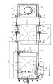
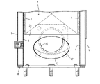
以下に、本発明を具体化した実施形態を図面に基づいて説明する。図1は排気ガス浄化装置の正面視断面図、図2は同外観底面図、図3は同排気ガス流入側から見た左側面図、図4は同排気ガス排出側から見た右側断面図、図5は図1の正面視分解断面図、図6は同排気ガス排出側の正面視拡大断面図、図7は同排気ガス排出側の側面視拡大断面図、図8は同排気ガス流入側の拡大底面図、図9は同排気ガス流入側の平面視拡大断面図である。図1乃至図5を参照しながら、排気ガス浄化装置の全体構造について説明する。なお、以下の説明では、排気ガス流入側を単に左側と称し、同じく排気ガス排出側を単に右側と称する。   DESCRIPTION OF EMBODIMENTS Embodiments embodying the present invention will be described below with reference to the drawings. 1 is a front sectional view of the exhaust gas purification device, FIG. 2 is a bottom view of the same, FIG. 3 is a left side view of the exhaust gas inflow side, and FIG. 4 is a right side sectional view of the exhaust gas purification device. 5 is an exploded front sectional view of FIG. 1, FIG. 6 is an enlarged front sectional view of the exhaust gas discharge side, FIG. 7 is an enlarged sectional side view of the exhaust gas discharge side, and FIG. FIG. 9 is an enlarged sectional view of the exhaust gas inflow side in plan view. The overall structure of the exhaust gas purification apparatus will be described with reference to FIGS. 1 to 5. In the following description, the exhaust gas inflow side is simply referred to as the left side, and the exhaust gas discharge side is also simply referred to as the right side.

図1乃至図5に示す如く、本実施形態の排気ガス浄化装置としての連続再生式のディーゼルパティキュレートフィルタ1(以下、DPFという)を設けている。DPF1は、排気ガス中の粒子状物質(PM)等を物理的に捕集するためのものである。DPF1は、二酸化窒素(NO を生成する白金等のディーゼル酸化触媒2と、捕集した粒子状物質(PM)を比較的低温で連続的に酸化除去するハニカム構造のスートフィルタ3とを、排気ガスの移動方向(図1の左側から右側方向)に直列に並べた構造になっている。DPF1は、スートフィルタ3が連続的に再生されるように構成している。DPF1によって、排気ガス中の粒子状物質(PM)の除去に加え、排気ガス中の一酸化炭素(CO)や炭化水素(HC)を低減できる。 As shown in FIGS. 1 to 5, a continuously regenerating diesel particulate filter 1 (hereinafter referred to as DPF) is provided as an exhaust gas purifying apparatus of the present embodiment. The DPF 1 is for physically collecting particulate matter (PM) and the like in the exhaust gas. The DPF 1 includes a diesel oxidation catalyst 2 such as platinum that generates nitrogen dioxide (NO 2 ), and a soot filter 3 having a honeycomb structure that continuously oxidizes and removes the collected particulate matter (PM) at a relatively low temperature. The exhaust gas is arranged in series in the moving direction of the exhaust gas (from the left side to the right side in FIG. 1). The DPF 1 is configured so that the soot filter 3 is continuously regenerated. The DPF 1 can reduce carbon monoxide (CO) and hydrocarbons (HC) in the exhaust gas in addition to the removal of particulate matter (PM) in the exhaust gas.

図1及び図5を参照して、ディーゼル酸化触媒2の取付け構造を説明する。図1及び図5に示す如く、エンジンが排出した排気ガスを浄化するガス浄化フィルタとしてのディーゼル酸化触媒2は、耐熱金属材料製の略筒型の触媒内側ケース4に内設させている。触媒内側ケース4は、耐熱金属材料製の略筒型の触媒外側ケース5に内設させている。即ち、ディーゼル酸化触媒2の外側にマット状のセラミックファイバー製触媒断熱材6を介して触媒内側ケース4を被嵌させている。また、触媒内側ケース4の外側に端面I字状の薄板製支持体7を介して触媒外側ケース5を被嵌させている。なお、触媒断熱材6によってディーゼル酸化触媒2が保護される。触媒内側ケース4に伝わる触媒外側ケース5の応力(変形力)を薄板製支持体7にて低減させる。   With reference to FIG.1 and FIG.5, the attachment structure of the diesel oxidation catalyst 2 is demonstrated. As shown in FIGS. 1 and 5, a diesel oxidation catalyst 2 as a gas purification filter for purifying exhaust gas discharged from an engine is installed in a substantially cylindrical catalyst inner case 4 made of a heat-resistant metal material. The catalyst inner case 4 is provided in a substantially cylindrical catalyst outer case 5 made of a heat-resistant metal material. That is, the catalyst inner case 4 is fitted on the outside of the diesel oxidation catalyst 2 via the mat-shaped ceramic fiber catalyst heat insulating material 6. Further, the catalyst outer case 5 is fitted on the outer side of the catalyst inner case 4 via a thin plate support 7 having an I-shaped end face. Note that the diesel oxidation catalyst 2 is protected by the catalyst heat insulating material 6. The stress (deformation force) of the catalyst outer case 5 transmitted to the catalyst inner case 4 is reduced by the thin plate support 7.

図1及び図5に示す如く、触媒内側ケース4及び触媒外側ケース5の左側端部に円板状の左側蓋体8を溶接にて固着している。左側蓋体8に座板体9を介してセンサ接続プラグ10を固着している。ディーゼル酸化触媒2の左側端面2aと左側蓋体8とをガス流入空間用一定距離L1だけ離間させて対向させる。ディーゼル酸化触媒2の左側端面2aと左側蓋体8との間に排気ガス流入空間11を形成している。なお、センサ接続プラグ10には、図示しない入口側排気ガス圧力センサや入口側排気ガス温度センサ等が接続される。   As shown in FIGS. 1 and 5, a disc-shaped left lid 8 is fixed to the left end of the catalyst inner case 4 and the catalyst outer case 5 by welding. A sensor connection plug 10 is fixed to the left lid body 8 through a seat plate body 9. The left end face 2a of the diesel oxidation catalyst 2 and the left lid 8 are opposed to each other with a predetermined distance L1 for gas inflow space. An exhaust gas inflow space 11 is formed between the left end face 2 a of the diesel oxidation catalyst 2 and the left lid 8. The sensor connection plug 10 is connected to an unillustrated inlet side exhaust gas pressure sensor, an inlet side exhaust gas temperature sensor, and the like.

図1、図5、図9に示す如く、排気ガス流入空間11が形成された触媒内側ケース4及び触媒外側ケース5の左側端部に楕円形状の排気ガス流入口12を開口させている。楕円形状の排気ガス流入口12は、排気ガス移動方向(前記ケース4,5の中心線方向)を短
尺直径とし、排気ガス移動方向(前記ケース4,5の円周方向)に直交する方向を長尺直径
に形成している。触媒内側ケース4の開口縁13と触媒外側ケース5の開口縁14の間に閉塞リング体15を挟持状に固着している。触媒内側ケース4の開口縁13と触媒外側ケース5の開口縁14の間の隙間が閉塞リング体15によって閉鎖される。触媒内側ケース4と触媒外側ケース5の間に排気ガスが流入するのを、閉塞リング体15によって防止している。
As shown in FIGS. 1, 5, and 9, an elliptical exhaust gas inlet 12 is opened at the left end of the catalyst inner case 4 and the catalyst outer case 5 in which the exhaust gas inflow space 11 is formed. The elliptical exhaust gas inlet 12 has a short diameter in the exhaust gas movement direction (center line direction of the cases 4 and 5) and a direction orthogonal to the exhaust gas movement direction (circumferential direction of the cases 4 and 5). It has a long diameter. A closing ring body 15 is fixed between the opening edge 13 of the catalyst inner case 4 and the opening edge 14 of the catalyst outer case 5 in a sandwiched manner. A gap between the opening edge 13 of the catalyst inner case 4 and the opening edge 14 of the catalyst outer case 5 is closed by the closing ring body 15. An exhaust ring 15 prevents the exhaust gas from flowing between the catalyst inner case 4 and the catalyst outer case 5.

図1、図3、図5、図8に示す如く、排気ガス流入口12が形成された触媒外側ケース5の外側面に排気ガス入口管16を配置している。排気ガス入口管16の小径側の真円形の開口端部16aに排気接続フランジ体17を溶接している。排気接続フランジ体17は、ボルト18を介して、後述するディーゼルエンジン70の排気マニホールド71に締結されている。排気ガス入口管16の大径側の真円形の開口端部16bは、触媒外側ケース5の外側面に溶接されている。排気ガス入口管16は、小径側の真円形の開口端部16aから大径側の真円形の開口端部16bに向けて末広がり形状(ラッパ状)に形成されている。   As shown in FIGS. 1, 3, 5, and 8, an exhaust gas inlet pipe 16 is disposed on the outer surface of the catalyst outer case 5 in which the exhaust gas inlet 12 is formed. An exhaust connection flange body 17 is welded to a true circular opening end portion 16 a on the small diameter side of the exhaust gas inlet pipe 16. The exhaust connection flange body 17 is fastened to an exhaust manifold 71 of a diesel engine 70 described later via bolts 18. A large circular opening end 16 b on the large diameter side of the exhaust gas inlet pipe 16 is welded to the outer surface of the catalyst outer case 5. The exhaust gas inlet pipe 16 is formed in a divergent shape (a trumpet shape) from the small-diameter-side perfect circular opening end 16a toward the large-diameter-side perfect circular opening end 16b.

図1、図5、図8に示す如く、触媒外側ケース5の外側面のうち、触媒外側ケース5の開口縁14の左側端部の外側面に、大径側の真円形の開口端部16bの左側端部が溶接されている。即ち、楕円形状の排気ガス流入口12に対して、排気ガス入口管16(大径側の真円形の開口端部16b)が、排気ガス移動下流側(触媒外側ケース5の右側)にオフセットされて配置されている。即ち、楕円形状の排気ガス流入口12は、排気ガス入口管16(大径側の真円形の開口端部16b)に対して、排気ガス移動上流側(触媒外側ケース5の左側)にオフセットされて、触媒外側ケース5に形成されている。   As shown in FIGS. 1, 5, and 8, of the outer surface of the catalyst outer case 5, a large circular opening end 16 b is formed on the outer surface of the left end of the opening edge 14 of the catalyst outer case 5. The left end of is welded. That is, with respect to the elliptical exhaust gas inlet 12, the exhaust gas inlet pipe 16 (the large circular opening end 16b) is offset downstream of the exhaust gas movement (on the right side of the catalyst outer case 5). Are arranged. That is, the elliptical exhaust gas inlet 12 is offset to the exhaust gas moving upstream side (the left side of the catalyst outer case 5) with respect to the exhaust gas inlet pipe 16 (the large circular opening end 16b). The catalyst outer case 5 is formed.

上記の構成により、エンジン70の排気ガスが、排気マニホールド71から排気ガス入口管16に入り込み、排気ガス入口管16から排気ガス流入口12を介して排気ガス流入空間11に入り込み、ディーゼル酸化触媒2にこの左側端面2aから供給される。ディーゼル酸化触媒2の酸化作用によって、二酸化窒素(NO が生成される。また、図2乃至図4に示す如く、触媒外側ケース5の外周面に支持脚体19を溶接している。エンジン70にDPF1を組付ける場合、後述するエンジン70のシリンダヘッド72等に、支持脚体19を介して、触媒外側ケース5を固着させる。 With the configuration described above, the exhaust gas of the engine 70 enters the exhaust gas inlet pipe 16 from the exhaust manifold 71, enters the exhaust gas inflow space 11 from the exhaust gas inlet pipe 16 through the exhaust gas inlet 12, and the diesel oxidation catalyst 2. From the left end face 2a. Nitrogen dioxide (NO 2 ) is generated by the oxidation action of the diesel oxidation catalyst 2. Further, as shown in FIGS. 2 to 4, support legs 19 are welded to the outer peripheral surface of the catalyst outer case 5. When the DPF 1 is assembled to the engine 70, the catalyst outer case 5 is fixed to the cylinder head 72 of the engine 70, which will be described later, via the support legs 19.

図1及び図5を参照して、スートフィルタ3の取付け構造を説明する。図1及び図5に示す如く、エンジン70が排出した排気ガスを浄化するガス浄化フィルタとしてのスートフィルタ3は、耐熱金属材料製の略筒型のフィルタ内側ケース20に内設させている。内側ケース4は、耐熱金属材料製の略筒型のフィルタ外側ケース21に内設させている。即ち、スートフィルタ3の外側にマット状のセラミックファイバー製フィルタ断熱材22を介してフィルタ内側ケース20を被嵌させている。なお、フィルタ断熱材22によってスートフィルタ3が保護される。   With reference to FIG.1 and FIG.5, the attachment structure of the soot filter 3 is demonstrated. As shown in FIGS. 1 and 5, the soot filter 3 as a gas purification filter for purifying exhaust gas discharged from the engine 70 is provided in a substantially cylindrical filter inner case 20 made of a heat-resistant metal material. The inner case 4 is provided in a substantially cylindrical filter outer case 21 made of a heat-resistant metal material. That is, the filter inner case 20 is fitted on the outside of the soot filter 3 via the mat-shaped ceramic fiber filter heat insulating material 22. The soot filter 3 is protected by the filter heat insulating material 22.

図1及び図5に示す如く、触媒外側ケース5の排気ガス移動下流側(右側)の端部に触媒側フランジ25を溶接する。フィルタ内側ケース20の排気ガス移動方向の中間と、フィルタ外側ケース21の排気ガス移動上流側(左側)の端部にフィルタ側フランジ26を溶接する。触媒側フランジ25と、フィルタ側フランジ26とを、ボルト27及びナット28によって着脱可能に締結している。なお、円筒形の触媒内側ケース4の直径寸法と、円筒形のフィルタ内側ケース20の直径寸法とが略同一寸法である。また、円筒形の触媒外側ケース5の直径寸法と、円筒形のフィルタ外側ケース21の直径寸法とが略同一寸法である。   As shown in FIGS. 1 and 5, the catalyst side flange 25 is welded to the exhaust gas movement downstream side (right side) of the catalyst outer case 5. The filter-side flange 26 is welded to the middle of the filter inner case 20 in the exhaust gas movement direction and the end of the filter outer case 21 on the upstream side (left side) of the exhaust gas movement. The catalyst side flange 25 and the filter side flange 26 are detachably fastened by bolts 27 and nuts 28. The diameter of the cylindrical catalyst inner case 4 and the diameter of the cylindrical filter inner case 20 are substantially the same. Further, the diameter of the cylindrical catalyst outer case 5 and the diameter of the cylindrical filter outer case 21 are substantially the same.

図1に示す如く、触媒側フランジ25とフィルタ側フランジ26を介して、触媒外側ケース5にフィルタ外側ケース21が連結された状態では、触媒内側ケース4の排気ガス移動下流側(右側)の端部に、フィルタ内側ケース20の排気ガス移動上流側(左側)の端部が、センサ取付け用一定間隔L2だけ離間して対峙する。即ち、触媒内側ケース4の排気ガス移動下流側(右側)の端部と、フィルタ内側ケース20の排気ガス移動上流側(左側)の端部との間に、センサ取付け空間29が形成される。センサ取付け空間29位置の触媒外側ケース5に、センサ接続プラグ50を固着している。センサ接続プラグ50には、図示しないフィルタ入口側排気ガス圧力センサやフィルタ入口側排気ガス温度センサ(サーミスタ)等が接続される。   As shown in FIG. 1, in a state where the filter outer case 21 is connected to the catalyst outer case 5 via the catalyst side flange 25 and the filter side flange 26, the exhaust gas movement downstream side (right side) end of the catalyst inner case 4 is shown. The end portion on the upstream side (left side) of the exhaust gas movement of the filter inner case 20 faces the portion spaced apart by a fixed interval L2 for sensor attachment. In other words, the sensor mounting space 29 is formed between the exhaust gas movement downstream side (right side) end of the catalyst inner case 4 and the exhaust gas movement upstream side (left side) end of the filter inner case 20. A sensor connection plug 50 is fixed to the catalyst outer case 5 at the sensor mounting space 29 position. The sensor connection plug 50 is connected to a filter inlet side exhaust gas pressure sensor (not shown), a filter inlet side exhaust gas temperature sensor (thermistor), and the like.

図5に示す如く、触媒内側ケース4の排気ガス移動方向の円筒長さL3よりも、触媒外側ケース5の排気ガス移動方向の円筒長さL4を長く形成している。フィルタ内側ケース20の排気ガス移動方向の円筒長さL5よりも、フィルタ外側ケース21の排気ガス移動方向の円筒長さL6を短く形成している。センサ取付け空間29の一定間隔L2と、触媒内側ケース4の円筒長さL3と、フィルタ内側ケース20の円筒長さL5とを加算した長さ(L2+L3+L5)が、触媒外側ケース5の円筒長さL4と、フィルタ外側ケース21の円筒長さL6とを加算した長さ(L4+L6)に略等しくなるように構成している。フィルタ外側ケース21の排気ガス移動上流側(左側)の端部から、フィルタ内側ケース20の排気ガス移動上流側(左側)の端部が、それらの長さの差(L7=L5−L6)だけ突出する。即ち、触媒外側ケース5にフィルタ外側ケース21を連結した場合、フィルタ内側ケース20の排気ガス移動上流側(左側)の端部が、オーバーラップ寸法L7だけ、触媒外側ケース5の排気ガス移動下流側(右側)に内挿される。   As shown in FIG. 5, the cylindrical length L4 of the catalyst outer case 5 in the exhaust gas movement direction is longer than the cylindrical length L3 of the catalyst inner case 4 in the exhaust gas movement direction. The cylindrical length L6 of the filter outer case 21 in the exhaust gas movement direction is shorter than the cylindrical length L5 of the filter inner case 20 in the exhaust gas movement direction. A length (L2 + L3 + L5) obtained by adding the constant interval L2 of the sensor mounting space 29, the cylindrical length L3 of the catalyst inner case 4 and the cylindrical length L5 of the filter inner case 20 is the cylindrical length L4 of the catalyst outer case 5. And a length (L4 + L6) obtained by adding the cylindrical length L6 of the filter outer case 21 to be substantially equal to each other. The exhaust gas movement upstream side (left side) end of the filter outer case 21 and the exhaust gas movement upstream side (left side) end of the filter inner case 20 are only the difference in length (L7 = L5−L6). Protruding. That is, when the filter outer case 21 is connected to the catalyst outer case 5, the exhaust gas movement upstream side (left side) end of the filter inner case 20 is the overlap dimension L7, and the exhaust gas movement downstream side of the catalyst outer case 5 (Right side) is interpolated.

上記の構成により、ディーゼル酸化触媒2の酸化作用によって生成された二酸化窒素(NO )が、スートフィルタ3にこの左側端面3aから供給される。スートフィルタ3に捕集されたディーゼルエンジン70の排気ガス中の捕集粒状物質(PM)が、二酸化窒素(NO によって、比較的低温で連続的に酸化除去される。ディーゼルエンジン70の排気ガス中の粒状物質(PM)の除去に加え、ディーゼルエンジン70の排気ガス中の一酸化炭素(CO)や炭化水素(HC)が低減される。 With the above configuration, nitrogen dioxide (NO 2 ) generated by the oxidation action of the diesel oxidation catalyst 2 is supplied to the soot filter 3 from the left end face 3a. The collected particulate matter (PM) in the exhaust gas of the diesel engine 70 collected by the soot filter 3 is continuously oxidized and removed at a relatively low temperature by nitrogen dioxide (NO 2 ) . In addition to the removal of particulate matter (PM) in the exhaust gas of the diesel engine 70, carbon monoxide (CO) and hydrocarbons (HC) in the exhaust gas of the diesel engine 70 are reduced.

なお、上記のように、エンジンが排出した排気ガスを浄化するガス浄化フィルタとして、ディーゼル酸化触媒2及びスートフィルタ3を設けたが、ディーゼル酸化触媒2及びスートフィルタ3に代えて、尿素(還元剤)の添加にて発生したアンモニア(NH によってエンジン70の排気ガス中の窒素酸化物(NOx)を還元するNOx選択還元触媒(NOx除去触媒)と、NOx選択還元触媒から排出される残留アンモニアを取り除くアンモニア除去触媒とを設けてもよい。 As described above, the diesel oxidation catalyst 2 and the soot filter 3 are provided as gas purification filters for purifying the exhaust gas discharged from the engine. However, instead of the diesel oxidation catalyst 2 and the soot filter 3, urea (reducing agent) is used. NOx selective reduction catalyst (NOx removal catalyst) for reducing nitrogen oxides (NOx) in the exhaust gas of the engine 70 by ammonia (NH 3 ) generated by the addition of), and residual ammonia discharged from the NOx selective reduction catalyst An ammonia removal catalyst that removes water may be provided.

上記のように、ガス浄化フィルタとして、触媒内側ケース4にNOx選択還元触媒(NOx除去触媒)を設け、フィルタ内側ケース20にアンモニア除去触媒を設けた場合、エンジンが排出した排気ガス中の窒素酸化物(NOx)が還元され、無害な窒素ガス(N として排出できる。 As described above, when a NOx selective reduction catalyst (NOx removal catalyst) is provided in the catalyst inner case 4 and an ammonia removal catalyst is provided in the filter inner case 20 as a gas purification filter, nitrogen oxidation in the exhaust gas exhausted by the engine is performed. The substance (NOx) is reduced and can be discharged as harmless nitrogen gas (N 2 ) .

図1乃至図5に示す如く、ディーゼルエンジン70が排出した排気ガスを浄化するガス浄化フィルタとしてのディーゼル酸化触媒2やスートフィルタ3と、ディーゼル酸化触媒2やスートフィルタ3を内設させる触媒内側ケース4やフィルタ内側ケース20と、触媒内側ケース4やフィルタ内側ケース20を内設させる触媒外側ケース5やフィルタ外側ケース21とを備えてなる排気ガス浄化装置において、触媒内側ケース4やフィルタ内側ケース20が触媒外側ケース5やフィルタ外側ケース21に連結され、外的な応力が付加される入口構成部品としての排気ガス入口管16及び支持体としての支持脚体19を触媒外側ケース5に配置している。   As shown in FIGS. 1 to 5, a diesel oxidation catalyst 2 and soot filter 3 as a gas purification filter for purifying exhaust gas discharged from a diesel engine 70, and a catalyst inner case in which the diesel oxidation catalyst 2 and the soot filter 3 are installed. 4, a filter inner case 20, and a catalyst outer case 5 and a filter outer case 21 in which the catalyst inner case 4 and the filter inner case 20 are installed. Are connected to the catalyst outer case 5 and the filter outer case 21, and an exhaust gas inlet pipe 16 as an inlet component to which an external stress is applied and a support leg 19 as a support body are arranged on the catalyst outer case 5. Yes.

したがって、触媒外側ケース5によって外的な応力を支持でき、触媒内側ケース4やフィルタ内側ケース20に変形力として作用する外的な応力を低減できる。触媒内側ケース4やフィルタ内側ケース20と触媒外側ケース5やフィルタ外側ケース21の二重構造によってディーゼル酸化触媒2やスートフィルタ3の断熱性を向上させて、ディーゼル酸化触媒2やスートフィルタ3の処理能力や再生能力を向上できるのに加えて、例えばエンジンからの振動の伝導や溶接加工の歪等によってディーゼル酸化触媒2やスートフィルタ3の支持が不適正になるのを簡単に防止できる。   Therefore, external stress can be supported by the catalyst outer case 5, and external stress acting as a deformation force on the catalyst inner case 4 and the filter inner case 20 can be reduced. The double structure of the catalyst inner case 4 or the filter inner case 20 and the catalyst outer case 5 or the filter outer case 21 improves the heat insulating properties of the diesel oxidation catalyst 2 or the soot filter 3, thereby treating the diesel oxidation catalyst 2 or the soot filter 3. In addition to improving the capacity and the regeneration capacity, it is possible to easily prevent improper support of the diesel oxidation catalyst 2 and the soot filter 3 due to, for example, conduction of vibrations from the engine or distortion in welding processing.

図1乃至図5に示す如く、複数組のディーゼル酸化触媒2やスートフィルタ3と、触媒内側ケース4やフィルタ内側ケース20と、触媒外側ケース5やフィルタ外側ケース21を備え、複数組の触媒外側ケース5やフィルタ外側ケース21をフランジ体としての触媒側フランジ25やフィルタ側フランジ26にて連結している。したがって、排気ガス入口管16及び支持脚体19の構成や、複数組のディーゼル酸化触媒2やスートフィルタ3間の排気ガスの移動等に考慮して、複数組の触媒内側ケース4やフィルタ内側ケース20や複数組の触媒外側ケース5やフィルタ外側ケース21を機能的に構成できる。複数組のディーゼル酸化触媒2やスートフィルタ3の処理能力や再生能力等を簡単に向上できる。   As shown in FIGS. 1 to 5, a plurality of sets of diesel oxidation catalysts 2 and soot filters 3, a catalyst inner case 4 and a filter inner case 20, and a catalyst outer case 5 and a filter outer case 21 are provided. The case 5 and the filter outer case 21 are connected by a catalyst side flange 25 and a filter side flange 26 as flange bodies. Accordingly, in consideration of the configuration of the exhaust gas inlet pipe 16 and the support leg 19 and the movement of exhaust gas between the plurality of sets of diesel oxidation catalyst 2 and the soot filter 3, a plurality of sets of catalyst inner cases 4 and filter inner cases are used. 20 and a plurality of sets of the catalyst outer case 5 and the filter outer case 21 can be functionally configured. The processing capacity, regeneration capacity, etc. of a plurality of sets of diesel oxidation catalysts 2 and soot filters 3 can be easily improved.

図1乃至図5に示す如く、触媒内側ケース4やフィルタ内側ケース20の排気ガスの移動方向の長さと、触媒外側ケース5やフィルタ外側ケース21の排気ガスの移動方向の長さを異ならせている。したがって、複数組のディーゼル酸化触媒2やスートフィルタ3の接合位置に対して、触媒外側ケース5やフィルタ外側ケース21を連結するフランジ体をオフセットさせて配置できる。複数組のディーゼル酸化触媒2やスートフィルタ3の取付け間隔を簡単に縮小又は拡大できる。   As shown in FIGS. 1 to 5, the length of the catalyst inner case 4 and the filter inner case 20 in the exhaust gas moving direction is different from the length of the catalyst outer case 5 and the filter outer case 21 in the exhaust gas moving direction. Yes. Accordingly, the flange body connecting the catalyst outer case 5 and the filter outer case 21 can be offset with respect to the joining position of the plurality of sets of the diesel oxidation catalyst 2 and the soot filter 3. The mounting interval of the plurality of sets of diesel oxidation catalysts 2 and soot filters 3 can be easily reduced or expanded.

図1乃至図5に示す如く、複数組のディーゼル酸化触媒2やスートフィルタ3と、触媒内側ケース4やフィルタ内側ケース20と、触媒外側ケース5やフィルタ外側ケース21を備え、複数組のディーゼル酸化触媒2やスートフィルタ3の接合位置に対して、複数組の触媒外側ケース5やフィルタ外側ケース21を連結する触媒側フランジ25やフィルタ側フランジ26をオフセットさせるように構成し、一方のスートフィルタ3に対向したフィルタ内側ケース20に、他方のディーゼル酸化触媒2に対向した触媒外側ケース5がオーバーラップするように構成している。   As shown in FIGS. 1 to 5, a plurality of sets of diesel oxidation catalysts 2 and soot filters 3, a catalyst inner case 4 and a filter inner case 20, a catalyst outer case 5 and a filter outer case 21 are provided. The soot filter 3 is configured such that the catalyst side flange 25 and the filter side flange 26 connecting the plurality of sets of the catalyst outer case 5 and the filter outer case 21 are offset with respect to the joining position of the catalyst 2 and the soot filter 3. A catalyst outer case 5 facing the other diesel oxidation catalyst 2 is configured to overlap with the filter inner case 20 facing the other.

したがって、複数組のディーゼル酸化触媒2やスートフィルタ3の接合間隔を縮小できるものでありながら、複数組のディーゼル酸化触媒2やスートフィルタ3の接合間にセンサ等を簡単に配置できる。複数組の触媒外側ケース5やフィルタ外側ケース21の排気ガス移動方向の長さを短縮して、複数組の触媒外側ケース5やフィルタ外側ケース21等の剛性の向上や軽量化を図ることができる。複数組のディーゼル酸化触媒2やスートフィルタ3の接合間隔を縮小して、複数組の触媒外側ケース5やフィルタ外側ケース21の排気ガス移動方向の長さを短縮できる。   Therefore, a sensor or the like can be easily disposed between the joints of the plurality of sets of diesel oxidation catalysts 2 and the soot filter 3 while the joint interval between the plurality of sets of diesel oxidation catalysts 2 and the soot filter 3 can be reduced. The lengths of the plurality of sets of catalyst outer cases 5 and filter outer cases 21 in the exhaust gas movement direction can be shortened to improve the rigidity and weight of the plurality of sets of catalyst outer cases 5 and filter outer cases 21 and the like. . By shortening the joining interval of the plurality of sets of diesel oxidation catalysts 2 and soot filters 3, the length of the plurality of sets of catalyst outer case 5 and filter outer case 21 in the exhaust gas moving direction can be shortened.

図1乃至図3、及び図5乃至図7を参照して、消音器30の取付け構造を説明する。図1乃至図3、図5に示す如く、エンジンが排出した排気ガス音を減衰させる消音器30は、耐熱金属材料製の略筒型の消音内側ケース31と、耐熱金属材料製の略筒型の消音外側ケース32と、消音内側ケース31及び消音外側ケース32の右側端部に溶接にて固着した円板状の右側蓋体33とを有する。消音外側ケース32に消音内側ケース31を内設させている。また、円筒形の触媒外側ケース5の直径寸法と、円筒形のフィルタ外側ケース21の直径寸法と、円筒形の消音外側ケース32とが略同一寸法である。円筒形の触媒内側ケース4の直径寸法と、円筒形のフィルタ内側ケース20の直径寸法と、円筒形の消音内側ケース31とが略同一寸法である。なお、円筒形の触媒内側ケース4の直径寸法と、円筒形のフィルタ内側ケース20の直径寸法と、円筒形の消音内側ケース31とが同一寸法でなくてもよい。   The mounting structure of the silencer 30 will be described with reference to FIGS. 1 to 3 and FIGS. 5 to 7. As shown in FIGS. 1 to 3 and 5, a silencer 30 for attenuating exhaust gas noise discharged from an engine includes a substantially cylindrical silencer inner case 31 made of a refractory metal material and a substantially cylindrical shape made of a refractory metal material. The sound-absorbing outer case 32, and the sound-absorbing inner case 31 and the right-side end portion of the sound-absorbing outer case 32 are fixed to each other by welding. A silencer inner case 31 is provided in the silencer outer case 32. Further, the diameter of the cylindrical catalyst outer case 5, the diameter of the cylindrical filter outer case 21, and the cylindrical silencing outer case 32 are substantially the same. The diameter size of the cylindrical catalyst inner case 4, the diameter size of the cylindrical filter inner case 20, and the cylindrical sound deadening inner case 31 are substantially the same size. The diameter size of the cylindrical catalyst inner case 4, the diameter size of the cylindrical filter inner case 20, and the cylindrical silencer inner case 31 may not be the same size.

図4乃至図7に示す如く、消音内側ケース31及び消音外側ケース32に排気ガス出口管34を貫通させている。排気ガス出口管34の一端側が出口蓋体35によって閉塞されている。消音内側ケース31の内部における排気ガス出口管34の全体に多数の排気孔36が開設されている。消音内側ケース31の内部が、多数の排気孔36を介して、排気ガス出口管34に連通されている。図示しない消音器やテールパイプが排気ガス出口管34の他端側に接続される。   As shown in FIGS. 4 to 7, the exhaust gas outlet pipe 34 is passed through the silencer inner case 31 and the silencer outer case 32. One end side of the exhaust gas outlet pipe 34 is closed by an outlet lid 35. A number of exhaust holes 36 are formed in the entire exhaust gas outlet pipe 34 inside the silencer inner case 31. The interior of the muffler inner case 31 is communicated with an exhaust gas outlet pipe 34 via a number of exhaust holes 36. A silencer and a tail pipe (not shown) are connected to the other end side of the exhaust gas outlet pipe 34.

図6、図7に示す如く、消音内側ケース31には、多数の消音孔37が開設されている。消音内側ケース31の内部が、多数の消音孔37を介して、消音内側ケース31と消音外側ケース32との間に連通されている。消音内側ケース31と消音外側ケース32との間の空間は、右側蓋体33と薄板製支持体38によって閉塞されている。消音内側ケース31と消音外側ケース32との間にセラミックファイバー製消音材39が充填されている。消音内側ケース31の排気ガス移動上流側(左側)の端部が、薄板製支持体38を介して、消音外側ケース32の排気ガス移動上流側(左側)の端部に連結されている。   As shown in FIGS. 6 and 7, the muffler inner case 31 has a large number of muffler holes 37. The interior of the silencer inner case 31 is communicated between the silencer inner case 31 and the silencer outer case 32 via a number of silencer holes 37. The space between the silencer inner case 31 and the silencer outer case 32 is closed by the right lid 33 and the thin plate support 38. A ceramic fiber silencer 39 is filled between the silencer inner case 31 and the silencer outer case 32. The exhaust gas movement upstream (left side) end of the muffler inner case 31 is connected to the exhaust gas movement upstream (left side) end of the muffler outer case 32 via a thin plate support 38.

上記の構成により、消音内側ケース31内から排気ガス出口管34を介して排気ガスが排出される。また、消音内側ケース31の内部において、多数の消音孔37から消音材39に排気ガス音(主に高周波帯の音)が吸音される。排気ガス出口管34の出口側から排出される排気ガスの騒音が減衰される。   With the above configuration, exhaust gas is discharged from the muffler inner case 31 through the exhaust gas outlet pipe 34. Further, in the silencer inner case 31, exhaust gas sounds (mainly high frequency band sounds) are absorbed into the silencer 39 from the numerous silencer holes 37. The noise of the exhaust gas discharged from the outlet side of the exhaust gas outlet pipe 34 is attenuated.

図1及び図5に示す如く、フィルタ内側ケース20とフィルタ外側ケース21の排気ガス移動下流側(右側)の端部にフィルタ側出口フランジ40を溶接する。消音外側ケース32の排気ガス移動上流側(左側)の端部に、消音側フランジ41を溶接する。フィルタ側出口フランジ40と、消音側フランジ41とを、ボルト42及びナット43によって着脱可能に締結している。なお、フィルタ内側ケース20とフィルタ外側ケース21にセンサ接続プラグ44を固着している。センサ接続プラグ44には、図示しない出口側排気ガス圧力センサや出口側排気ガス温度センサ(サーミスタ)等が接続される。   As shown in FIGS. 1 and 5, the filter side outlet flange 40 is welded to the exhaust gas movement downstream side (right side) end of the filter inner case 20 and the filter outer case 21. The silencer flange 41 is welded to the exhaust gas movement upstream side (left side) of the silencer outer case 32. The filter side outlet flange 40 and the silencer side flange 41 are detachably fastened by bolts 42 and nuts 43. A sensor connection plug 44 is fixed to the filter inner case 20 and the filter outer case 21. The sensor connection plug 44 is connected to an unillustrated outlet side exhaust gas pressure sensor, an outlet side exhaust gas temperature sensor (thermistor) and the like.

図10乃至図14を参照して、排気ガス流入口12の変形構造を説明する。上記実施形態において、図9に示す如く、排気ガス流入口12は、触媒内側ケース4及び触媒外側ケース5に略楕円形の貫通孔を開設することによって形成していた。図10に示す如く、触媒内側ケース4及び触媒外側ケース5に略四角形の貫通孔を開設することによって排気ガス流入口12を形成できる。また、図11に示す如く、触媒内側ケース4及び触媒外側ケース5に略長円形の貫通孔を開設することによって排気ガス流入口12を形成できる。また、図12に示す如く、触媒内側ケース4及び触媒外側ケース5に略多角形の貫通孔を開設することによって排気ガス流入口12を形成できる。また、図13に示す如く、触媒内側ケース4及び触媒外側ケース5に略六角形の貫通孔を開設することによって排気ガス流入口12を形成できる。また、図14に示す如く、触媒内側ケース4及び触媒外側ケース5に不定形の貫通孔を開設することによって排気ガス流入口12を形成できる。   A modified structure of the exhaust gas inlet 12 will be described with reference to FIGS. 10 to 14. In the above embodiment, as shown in FIG. 9, the exhaust gas inlet 12 is formed by opening substantially elliptical through holes in the catalyst inner case 4 and the catalyst outer case 5. As shown in FIG. 10, the exhaust gas inlet 12 can be formed by opening substantially rectangular through holes in the catalyst inner case 4 and the catalyst outer case 5. Further, as shown in FIG. 11, the exhaust gas inlet 12 can be formed by opening a substantially oval through hole in the catalyst inner case 4 and the catalyst outer case 5. In addition, as shown in FIG. 12, the exhaust gas inlet 12 can be formed by opening substantially polygonal through holes in the catalyst inner case 4 and the catalyst outer case 5. Further, as shown in FIG. 13, the exhaust gas inlet 12 can be formed by opening substantially hexagonal through holes in the catalyst inner case 4 and the catalyst outer case 5. Further, as shown in FIG. 14, the exhaust gas inlet 12 can be formed by opening an indeterminate through hole in the catalyst inner case 4 and the catalyst outer case 5.

図15乃至図18を参照して、ディーゼルエンジン70に前記DPF1を設けた構造を説明する。図15乃至図18に示す如く、ディーゼルエンジン70のシリンダヘッド72の左右側面に、排気マニホールド71と、吸気マニホールド73とが配置されている。シリンダヘッド72は、エンジン出力軸74(クランク軸)とピストン(図示省略)を有するシリンダブロック75に上載される。シリンダブロック75の前面と後面からエンジン出力軸74の前端と後端を突出させる。シリンダブロック75の前面に冷却ファン76を設ける。エンジン出力軸74の前端側からVベルト77を介して冷却ファン76に回転力を伝達するように構成している。   With reference to FIG. 15 thru | or FIG. 18, the structure which provided the said DPF1 in the diesel engine 70 is demonstrated. As shown in FIGS. 15 to 18, an exhaust manifold 71 and an intake manifold 73 are arranged on the left and right side surfaces of the cylinder head 72 of the diesel engine 70. The cylinder head 72 is mounted on a cylinder block 75 having an engine output shaft 74 (crankshaft) and a piston (not shown). The front end and the rear end of the engine output shaft 74 are projected from the front and rear surfaces of the cylinder block 75. A cooling fan 76 is provided on the front surface of the cylinder block 75. The rotational force is transmitted from the front end side of the engine output shaft 74 to the cooling fan 76 via the V belt 77.

また、図18に示す如く、シリンダブロック75の後面にフライホイールハウジング78を固着している。フライホイールハウジング78にフライホイール79を内設する。エンジン出力軸74の後端側にフライホイール79を軸支させている。後述するバックホウ100やフォークリフト120等の作動部に、フライホイール79を介してディーゼルエンジン70の動力を取出すように構成している。また、図15に示す如く、シリンダヘッド72に支持脚体19をボルト80にて着脱可能に締結している。上記したDPF1は、支持脚体19を介して、高剛性のシリンダヘッド72に支持されるように構成している。   Further, as shown in FIG. 18, a flywheel housing 78 is fixed to the rear surface of the cylinder block 75. A flywheel 79 is installed in the flywheel housing 78. A flywheel 79 is pivotally supported on the rear end side of the engine output shaft 74. The power of the diesel engine 70 is taken out via a flywheel 79 to operating parts such as a backhoe 100 and a forklift 120 described later. Further, as shown in FIG. 15, the support leg 19 is detachably fastened to the cylinder head 72 with a bolt 80. The DPF 1 described above is configured to be supported by the highly rigid cylinder head 72 via the support leg 19.

図19及び図20を参照して、バックホウ100に前記ディーゼルエンジン70を搭載した構造を説明する。図19及び図20に示す如く、バックホウ100は、左右一対の走行クローラ103を有する履帯式の走行装置102と、走行装置102上に設けられた旋回機体104とを備えている。旋回機体104は、図示しない旋回用油圧モータによって、360°の全方位にわたって水平旋回可能に構成されている。走行装置102の後部には、対地作業用の土工板105が昇降動可能に装着されている。旋回機体104の左側部には、操縦部106とディーゼルエンジン70とが搭載されている。旋回機体104の右側部には、掘削作業のためのブーム111及びバケット113を有する作業部110が設けられている。   A structure in which the diesel engine 70 is mounted on the backhoe 100 will be described with reference to FIGS. 19 and 20. As shown in FIGS. 19 and 20, the backhoe 100 includes a crawler-type traveling device 102 having a pair of left and right traveling crawlers 103, and a turning machine body 104 provided on the traveling device 102. The revolving machine body 104 is configured to be horizontally revolved over 360 ° in all directions by a revolving hydraulic motor (not shown). An earthwork plate 105 for ground work is mounted on the rear part of the traveling device 102 so as to be movable up and down. A steering unit 106 and a diesel engine 70 are mounted on the left side of the revolving machine body 104. A working unit 110 having a boom 111 and a bucket 113 for excavation work is provided on the right side of the revolving machine body 104.

操縦部106には、オペレータが着座する操縦座席108と、ディーゼルエンジン70等を出力操作する操作手段や、作業部110用の操作手段としてのレバー又はスイッチ等が配置されている。作業部110の構成要素であるブーム111には、ブームシリンダ112とバケットシリンダ114とが配置されている。ブーム111の先端部には、掘削用アタッチメントとしてのバケット113が、掬い込み回動可能に枢着されている。ブームシリンダ112又はバケットシリンダ114を作動させて、バケット113によって土工作業(作溝等の対地作業)を実行するように構成している。   The control unit 106 is provided with a control seat 108 on which an operator is seated, operation means for operating the diesel engine 70 and the like, and a lever or switch as an operation means for the work unit 110. A boom cylinder 112 and a bucket cylinder 114 are arranged on a boom 111 which is a component of the working unit 110. A bucket 113 as an attachment for excavation is pivotally attached to the tip end portion of the boom 111 so as to be inserted and rotated. The boom cylinder 112 or the bucket cylinder 114 is operated to perform earthwork work (ground work such as grooving) by the bucket 113.

図21及び図22を参照して、フォークリフトカー120に前記ディーゼルエンジン70を搭載した構造を説明する。図21及び図22に示す如く、フォークリフトカー120は、左右一対の前輪122及び後輪123を有する走行機体124を備えている。走行機体124には、操縦部125とディーゼルエンジン70とが搭載されている。走行機体124の前側部には、荷役作業のためのフォーク126を有する作業部127が設けられている。操縦部125には、オペレータが着座する操縦座席128と、操縦ハンドル129と、ディーゼルエンジン70等を出力操作する操作手段や、作業部127用の操作手段としてのレバー又はスイッチ等が配置されている。   A structure in which the diesel engine 70 is mounted on the forklift car 120 will be described with reference to FIGS. 21 and 22. As shown in FIGS. 21 and 22, the forklift car 120 includes a traveling machine body 124 having a pair of left and right front wheels 122 and a rear wheel 123. The traveling body 124 is equipped with a control unit 125 and a diesel engine 70. A working portion 127 having a fork 126 for cargo handling work is provided on the front side portion of the traveling machine body 124. In the control unit 125, a control seat 128 on which an operator is seated, a control handle 129, an operation means for operating the diesel engine 70 and the like, a lever or a switch as an operation means for the working unit 127, and the like are disposed. .

作業部127の構成要素であるマスト130には、フォーク126が昇降可能に配置されている。フォーク126を昇降動させて、荷物を積んだパレット(図示省略)をフォーク126に上載させ、走行機体124を前後進移動させて、前記パレットの運搬等の荷役作業を実行するように構成している。   A fork 126 is arranged on the mast 130 that is a component of the working unit 127 so as to be movable up and down. The fork 126 is moved up and down, a pallet (not shown) loaded with a load is placed on the fork 126, the traveling machine body 124 is moved forward and backward, and a cargo handling operation such as transportation of the pallet is performed. Yes.

2 ディーゼル酸化触媒(ガス浄化フィルタ)
3 スートフィルタ(ガス浄化フィルタ)
4 触媒内側ケース
5 触媒外側ケース
16 排気ガス入口管(入口構成部品)
19 支持脚体(支持体)
20 フィルタ内側ケース
21 フィルタ外側ケース
25 触媒側フランジ(フランジ体)
26 フィルタ側フランジ(フランジ体)
2 Diesel oxidation catalyst (gas purification filter)
3 Soot filter (gas purification filter)
4 Catalyst inner case 5 Catalyst outer case 16 Exhaust gas inlet pipe (inlet component)
19 Support leg (support)
20 Filter inner case 21 Filter outer case 25 Catalyst side flange (flange body)
26 Filter side flange (flange body)

Claims (1)

エンジンが排出した排気ガスを浄化する複数のガス浄化フィルタと、前記各ガス浄化フィルタを内設させる複数の内側ケースと、前記各内側ケースを内設させる複数の外側ケースとを有する排気ガス浄化装置を備えたエンジン装置であって、
前記内側ケースの排気ガスの移動方向の長さと、前記外側ケースの排気ガスの移動方向の長さを異ならせ、前記複数組の外側ケースをフランジ体にて連結し、前記複数組のガス浄化フィルタの接合位置に対して、前記複数組の外側ケースを連結する前記フランジ体をオフセットさせ、一方の前記ガス浄化フィルタに対向した前記内側ケースに、他方の前記ガス浄化フィルタに対向した前記外側ケースをオーバーラップさせるように構成し、
前記外側ケースに設けられた排気ガス入口管及び支持体を介して、前記エンジンに前記排気ガス浄化装置を支持させている、
エンジン装置。
A plurality of gas purifying filter for purifying exhaust gases the engine is discharged, the plurality of the inner casing which internally provided with the gas purifying filter, the exhaust gas purification device having a plurality of outer cases is provided inside each of said inner casing An engine device comprising :
The length of the moving direction of exhaust gas in the inner casing, the made different from the moving direction of the exhaust gas of the outer case length, the plurality of sets of the outer case connected with the flange body, said plurality of sets of gas purification The flange case connecting the plurality of sets of outer cases is offset with respect to the joining position of the filter, the inner case facing one of the gas purification filters, and the outer case facing the other gas purification filter Configured to overlap,
The exhaust gas purification device is supported by the engine via an exhaust gas inlet pipe and a support provided in the outer case.
Engine equipment.
JP2010163174A 2010-07-20 2010-07-20 Engine equipment Active JP5269007B2 (en)

Priority Applications (1)

Application Number Priority Date Filing Date Title
JP2010163174A JP5269007B2 (en) 2010-07-20 2010-07-20 Engine equipment

Applications Claiming Priority (1)

Application Number Priority Date Filing Date Title
JP2010163174A JP5269007B2 (en) 2010-07-20 2010-07-20 Engine equipment

Related Parent Applications (1)

Application Number Title Priority Date Filing Date
JP2008240369A Division JP5164762B2 (en) 2008-09-19 2008-09-19 Exhaust gas purification device

Related Child Applications (1)

Application Number Title Priority Date Filing Date
JP2013097994A Division JP2013155747A (en) 2013-05-07 2013-05-07 Exhaust emission control device

Publications (3)

Publication Number Publication Date
JP2010285994A JP2010285994A (en) 2010-12-24
JP2010285994A5 JP2010285994A5 (en) 2012-01-19
JP5269007B2 true JP5269007B2 (en) 2013-08-21

Family

ID=43541856

Family Applications (1)

Application Number Title Priority Date Filing Date
JP2010163174A Active JP5269007B2 (en) 2010-07-20 2010-07-20 Engine equipment

Country Status (1)

Country Link
JP (1) JP5269007B2 (en)

Families Citing this family (1)

* Cited by examiner, † Cited by third party
Publication number Priority date Publication date Assignee Title
CN108716429B (en) * 2018-05-18 2020-08-28 江苏大学 Movable and easy regenerated granule entrapment device

Family Cites Families (5)

* Cited by examiner, † Cited by third party
Publication number Priority date Publication date Assignee Title
JP4115120B2 (en) * 2001-08-06 2008-07-09 株式会社小松製作所 Exhaust gas purification device for internal combustion engine
JP4202787B2 (en) * 2003-02-28 2008-12-24 カルソニックカンセイ株式会社 Diesel particulate filter device
JP2005083304A (en) * 2003-09-10 2005-03-31 Toyota Motor Corp Exhaust emission control device of internal combustion engine
JP4091009B2 (en) * 2004-03-09 2008-05-28 日産ディーゼル工業株式会社 Engine exhaust purification system
JP4519570B2 (en) * 2004-08-20 2010-08-04 ヤンマー株式会社 engine

Also Published As

Publication number Publication date
JP2010285994A (en) 2010-12-24

Similar Documents

Publication Publication Date Title
JP5185751B2 (en) Exhaust gas purification device
JP2010071184A5 (en)
JP4963304B2 (en) Exhaust gas purification device
JP2010071207A5 (en)
JP5164762B2 (en) Exhaust gas purification device
JP2010071208A5 (en)
JP5269007B2 (en) Engine equipment
JP5285368B2 (en) Engine equipment
JP5285369B2 (en) Engine equipment
JP2010071182A (en) Exhaust emission control device
JP5923543B2 (en) Exhaust gas purification device
JP5523504B2 (en) Engine equipment
JP5235575B2 (en) Exhaust gas purification device
JP5509258B2 (en) Engine equipment
JP5231146B2 (en) Exhaust gas purification device
JP2010285994A5 (en)
JP5825725B2 (en) Exhaust gas purification device
JP5399336B2 (en) Exhaust gas purification device
JP5525086B2 (en) Exhaust gas purification device
JP5443530B2 (en) Exhaust gas purification device
JP5654520B2 (en) Engine equipment
JP5793212B2 (en) Engine equipment
JP5632508B2 (en) Engine equipment
JP2015108377A (en) Engine device
JP5285370B2 (en) Engine equipment

Legal Events

Date Code Title Description
A621 Written request for application examination

Free format text: JAPANESE INTERMEDIATE CODE: A621

Effective date: 20110810

A521 Written amendment

Free format text: JAPANESE INTERMEDIATE CODE: A523

Effective date: 20111121

A977 Report on retrieval

Free format text: JAPANESE INTERMEDIATE CODE: A971007

Effective date: 20130322

TRDD Decision of grant or rejection written
A01 Written decision to grant a patent or to grant a registration (utility model)

Free format text: JAPANESE INTERMEDIATE CODE: A01

Effective date: 20130403

A61 First payment of annual fees (during grant procedure)

Free format text: JAPANESE INTERMEDIATE CODE: A61

Effective date: 20130507

R150 Certificate of patent or registration of utility model

Ref document number: 5269007

Country of ref document: JP

Free format text: JAPANESE INTERMEDIATE CODE: R150

Free format text: JAPANESE INTERMEDIATE CODE: R150

S531 Written request for registration of change of domicile

Free format text: JAPANESE INTERMEDIATE CODE: R313531

R350 Written notification of registration of transfer

Free format text: JAPANESE INTERMEDIATE CODE: R350

R250 Receipt of annual fees

Free format text: JAPANESE INTERMEDIATE CODE: R250

S533 Written request for registration of change of name

Free format text: JAPANESE INTERMEDIATE CODE: R313533

R350 Written notification of registration of transfer

Free format text: JAPANESE INTERMEDIATE CODE: R350