JP4963304B2 - Exhaust gas purification device - Google Patents
Exhaust gas purification device Download PDFInfo
- Publication number
- JP4963304B2 JP4963304B2 JP2008240368A JP2008240368A JP4963304B2 JP 4963304 B2 JP4963304 B2 JP 4963304B2 JP 2008240368 A JP2008240368 A JP 2008240368A JP 2008240368 A JP2008240368 A JP 2008240368A JP 4963304 B2 JP4963304 B2 JP 4963304B2
- Authority
- JP
- Japan
- Prior art keywords
- exhaust gas
- outer case
- catalyst
- filter
- inner case
- Prior art date
- Legal status (The legal status is an assumption and is not a legal conclusion. Google has not performed a legal analysis and makes no representation as to the accuracy of the status listed.)
- Active
Links
Images


Description
本発明は、ディーゼルエンジン等に搭載する排気ガス浄化装置に係り、より詳しくは、排気ガス中に含まれた粒子状物質(すす、パティキュレート)、又はNOx(窒素酸化物)等を除去する排気ガス浄化装置に関するものである。 The present invention relates to an exhaust gas purification device mounted on a diesel engine or the like, and more specifically, exhaust gas that removes particulate matter (soot, particulates) or NOx (nitrogen oxide) contained in the exhaust gas. The present invention relates to a gas purification device.
従来、ディーゼルエンジン等に適用される排気ガス浄化装置において、走行機体等に搭載されるディーゼルエンジンの排気ガス排出径路中に、ディーゼルパティキュレートフィルタ(又はNOx触媒)等が設けられ、ディーゼルエンジンから排出された排気ガスが、ディーゼルパティキュレートフィルタ(又はNOx触媒)等によって浄化処理されるようにした技術がある(特許文献1、特許文献2、特許文献3)。また、ケーシング(外側ケース)内にフィルタケース(内側ケース)を設け、フィルタケース内にパティキュレートフィルタを配置する技術も公知である(特許文献4参照)。
ケーシング内にパティキュレートフィルタを配置した構造において、円筒形状のケーシング内に、円筒形状の中心線に直交するせん断方向からエンジンの排気ガスを入れる場合、ケーシングの中心に向かってエンジンの排気ガス用の入口管を挿入し、入口管の外側に補強部材を溶接していたから、ケーシングの入口管用の挿入口の中心、入口管の中心、補強部材の中心が同一位置になる。そのため、最も取付け幅が広くなる部材に合わせて、ケーシングの入口管用の挿入口の形成位置(パティキュレートフィルタの取付け位置)を決定して、入口管や補強部材をケーシングに設ける必要があった。即ち、入口管よりも排気ガスの下流側にパティキュレートフィルタの排気ガス上流側端面を配置させる必要があるから、パティキュレートフィルタの排気ガス上流側のケーシングの排気ガス移動方向の長さを簡単に短縮できない等の問題がある。 In the structure in which the particulate filter is arranged in the casing, when the engine exhaust gas is put into the cylindrical casing from the shear direction perpendicular to the center line of the cylindrical shape, the exhaust gas for the engine exhaust toward the center of the casing. Since the inlet pipe is inserted and the reinforcing member is welded to the outside of the inlet pipe, the center of the inlet for the inlet pipe of the casing, the center of the inlet pipe, and the center of the reinforcing member are in the same position. Therefore, it is necessary to determine the formation position of the insertion port for the inlet pipe of the casing (attachment position of the particulate filter) in accordance with the member having the largest attachment width, and to provide the inlet pipe and the reinforcing member on the casing. That is, since it is necessary to arrange the exhaust gas upstream end face of the particulate filter on the downstream side of the exhaust gas from the inlet pipe, the length of the exhaust gas moving direction of the casing on the exhaust gas upstream side of the particulate filter can be simplified. There is a problem that it cannot be shortened.
本発明の目的は、ガス浄化フィルタ(パティキュレートフィルタのフィルタ本体)の設置部寄りに排気ガス入口管を配置でき、ガス浄化フィルタの排気ガス上流側のケーシングの排気ガス移動方向の長さを簡単に短縮できるようにした排気ガス浄化装置を提供するものである。 An object of the present invention is to arrange an exhaust gas inlet pipe near the installation part of a gas purification filter (filter body of a particulate filter), and to simplify the length of the casing on the upstream side of the exhaust gas of the gas purification filter in the exhaust gas movement direction. The present invention provides an exhaust gas purification device that can be shortened.
前記目的を達成するため、請求項1に係る発明の排気ガス浄化装置は、エンジンが排出した排気ガスを浄化するガス浄化フィルタと、前記ガス浄化フィルタを内設させる内側ケースと、前記内側ケースを内設させる外側ケースとを備えてなる排気ガス浄化装置において、前記内側ケース及び前記外側ケースの一端側の周面に排気ガス入口を形成し、前記外側ケースの外周のうち前記排気ガス入口の外側に入口管を配置し、前記入口管の排気ガス入口側の開口端面の面積よりも、前記入口管の排気ガス出口側の開口端面の面積を大きく形成し、前記外側ケースの排気ガス移動方向で、前記外側ケース及び前記内側ケースの排気ガス入口の開口寸法よりも、前記入口管の排気ガス出口側の開口寸法を大きく形成したものである。 In order to achieve the above object, an exhaust gas purifying apparatus according to a first aspect of the present invention includes a gas purification filter that purifies exhaust gas discharged from an engine, an inner case in which the gas purification filter is installed, and the inner case. In the exhaust gas purifying apparatus comprising an outer case provided inside, an exhaust gas inlet is formed on a peripheral surface on one end side of the inner case and the outer case, and an outer periphery of the outer case is outside the exhaust gas inlet. the inlet pipe is disposed, than the area of the open end surface of the exhaust gas inlet side of the inlet pipe, the area of the opening end surface of the exhaust gas outlet side of the inlet pipe formed larger, the exhaust gas moving direction of the outer casing The opening size on the exhaust gas outlet side of the inlet pipe is formed larger than the opening size of the exhaust gas inlet of the outer case and the inner case .
請求項2に記載の発明は、請求項1に記載の排気ガス浄化装置において、前記入口管の排気ガス出口側のうち排気ガス移動下流側の端部よりも、前記ガス浄化フィルタの排気ガス移動上流側の端面が、前記外側ケースの排気ガス移動上流側に配置されるように構成したものである。 According to a second aspect of the present invention, in the exhaust gas purifying device according to the first aspect, the exhaust gas movement of the gas purification filter is more than the end of the exhaust gas outlet side of the inlet pipe on the downstream side of the exhaust gas movement. The upstream end surface is configured to be arranged on the exhaust gas movement upstream side of the outer case.
請求項3に記載の発明は、請求項1に記載の排気ガス浄化装置において、前記外側ケースの排気ガス入口の開口縁のうち、排気ガス移動上流側の排気ガス入口の開口縁に、前記入口管の排気ガス出口側の端部を連結させるように構成したものである。 According to a third aspect of the present invention, in the exhaust gas purifying apparatus according to the first aspect, among the opening edges of the exhaust gas inlet of the outer case, the inlet of the exhaust gas inlet upstream of the exhaust gas movement is connected to the inlet. The end of the pipe on the exhaust gas outlet side is connected.
請求項4に記載の発明は、請求項1に記載の排気ガス浄化装置において、前記外側ケース及び前記内側ケースの排気ガス入口の開口形状が、排気ガス移動方向を短径とし、これと交差する方向を長径とする長円又は多角形状に形成されているというものである。 According to a fourth aspect of the present invention, in the exhaust gas purifying device according to the first aspect, the opening shape of the exhaust gas inlet of the outer case and the inner case has a short diameter in the exhaust gas moving direction and intersects this. It is formed in the shape of an ellipse or a polygon whose major axis is the direction.
請求項1に記載の発明によれば、エンジンが排出した排気ガスを浄化するガス浄化フィルタと、前記ガス浄化フィルタを内設させる内側ケースと、前記内側ケースを内設させる外側ケースとを備えてなる排気ガス浄化装置において、前記内側ケース及び前記外側ケースの一端側の周面に排気ガス入口を形成し、前記外側ケースの外周のうち前記排気ガス入口の外側に入口管を配置し、前記入口管の排気ガス入口側の開口端面の面積よりも、前記入口管の排気ガス出口側の開口端面の面積を大きく形成したものであるから、前記ガス浄化フィルタ設置部寄りに排気ガス入口管を配置でき、前記ガス浄化フィルタの排気ガス上流側の前記外側ケース(ケーシング)の排気ガス移動方向の長さを簡単に短縮できる。即ち、前記外側ケースの排気ガス移動方向の上流側の端面に前記ガス浄化フィルタの端面を簡単に接近させて配置できる。また、前記入口管の排気ガス入口側の開口端面の面積よりも、前記入口管の排気ガス出口側の開口端面の面積を大きく形成することによって、前記外側ケースの外周面に前記入口管を溶接でき、従来のような前記外側ケースと前記入口管の連結用の補強部材を設けることなく、前記外側ケースの排気ガス入口側における前記入口管の取付け強度を維持しながら、前記外側ケースや前記入口管における排気ガスの排気圧損失を低減できる。 According to the first aspect of the present invention, there is provided a gas purification filter for purifying exhaust gas discharged from the engine, an inner case for installing the gas purification filter, and an outer case for installing the inner case. In the exhaust gas purification apparatus, an exhaust gas inlet is formed on a peripheral surface on one end side of the inner case and the outer case, an inlet pipe is disposed outside the exhaust gas inlet in an outer periphery of the outer case, and the inlet Since the area of the opening end face on the exhaust gas outlet side of the inlet pipe is formed larger than the area of the opening end face on the exhaust gas inlet side of the pipe, the exhaust gas inlet pipe is disposed near the gas purification filter installation portion In addition, the length of the outer case (casing) on the upstream side of the exhaust gas of the gas purification filter can be easily shortened. That is, the end face of the gas purification filter can be easily brought close to the upstream end face of the outer case in the exhaust gas movement direction. Further, the inlet pipe is welded to the outer peripheral surface of the outer case by forming the area of the opening end face on the exhaust gas outlet side of the inlet pipe larger than the area of the opening end face on the exhaust gas inlet side of the inlet pipe. The outer case and the inlet can be maintained while maintaining the attachment strength of the inlet pipe on the exhaust gas inlet side of the outer case without providing a reinforcing member for connecting the outer case and the inlet pipe as in the prior art. The exhaust pressure loss of the exhaust gas in the pipe can be reduced.
また、前記外側ケースの排気ガス移動方向で、前記外側ケース及び前記内側ケースの排気ガス入口の開口寸法よりも、前記入口管の排気ガス出口側の開口寸法を大きく形成したものであるから、従来のような補強部材を設けることなく、前記外側ケースの排気ガス入口側における前記入口管の取付け強度を維持でき、前記入口管や前記外側ケースの排気ガス入口等の排気圧損失を低減できる。従来の補強部材を設けた構造に比べて、構成部品数を削減して低コストに構成できる。前記外側ケースの外形をコンパクトに形成でき、且つ軽量化等を簡単に図ることができるものでありながら、前記外側ケースや前記入口管等の排気ガス入口側を高剛性に構成できる。即ち、前記外側ケースの排気ガス移動方向の上流側の側端面に近接させて、前記外側ケース及び前記内側ケースの排気ガス入口を形成できる。前記外側ケースの排気ガス移動方向の寸法を短縮して、従来よりも部品数を少なくし、低コストで、コンパクトに且つ軽量に構成できる。 Further, in the exhaust gas movement direction of the outer case, the opening size on the exhaust gas outlet side of the inlet pipe is formed larger than the opening size of the exhaust gas inlet of the outer case and the inner case. Without providing such a reinforcing member, the mounting strength of the inlet pipe on the exhaust gas inlet side of the outer case can be maintained, and exhaust pressure loss at the inlet pipe and the exhaust gas inlet of the outer case can be reduced. Compared to a conventional structure provided with a reinforcing member, the number of components can be reduced and the structure can be reduced. The outer case can be formed compactly and the exhaust gas inlet side such as the outer case and the inlet pipe can be configured with high rigidity, while the weight can be easily reduced. That is, the exhaust gas inlets of the outer case and the inner case can be formed close to the side end surface on the upstream side in the exhaust gas movement direction of the outer case. By reducing the dimension of the outer case in the exhaust gas movement direction, the number of parts can be reduced as compared with the conventional case, and the configuration can be made compact and lightweight at low cost.
請求項2に記載の発明によれば、前記入口管の排気ガス出口側のうち排気ガス移動下流側の端部よりも、前記ガス浄化フィルタの排気ガス移動上流側の端面が、前記外側ケースの排気ガス移動上流側に配置されるように構成したものであるから、前記外側ケースの排気ガス移動方向の長さのうち排気ガス上流側の長さを簡単に短縮でき、前記外側ケースの排気ガス移動方向の長さをコンパクトに形成できる。 According to the second aspect of the present invention, the end surface on the exhaust gas movement upstream side of the exhaust gas movement side of the exhaust gas outlet side of the inlet pipe has an end surface on the exhaust gas movement upstream side of the outer case. Since it is configured to be disposed upstream of the exhaust gas movement, the length of the outer case upstream of the length of the outer case in the exhaust gas movement direction can be easily reduced, and the exhaust gas of the outer case can be reduced. The length in the moving direction can be made compact.
請求項3に記載の発明によれば、前記外側ケースの排気ガス入口の開口縁のうち、排気ガス移動上流側の排気ガス入口の開口縁に、前記入口管の排気ガス出口側の端部を連結させるように構成したものであるから、前記外側ケースの排気ガス移動方向の長さのうち排気ガス上流側の長さを簡単に短縮できるものでありながら、前記外側ケースや前記入口管における排気ガスの排気圧損失を低減できる。 According to the third aspect of the present invention, the exhaust gas outlet side end portion of the inlet pipe is connected to the exhaust gas inlet upstream edge of the exhaust gas movement among the exhaust gas inlet opening edge of the outer case. Since the length of the outer case in the exhaust gas movement direction can be easily shortened, the exhaust gas in the outer case or the inlet pipe can be easily shortened. Gas exhaust pressure loss can be reduced.
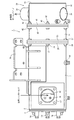
以下に、本発明を具体化した実施形態を図面に基づいて説明する。図1は排気ガス浄化装置の正面視断面図、図2は同外観底面図、図3同排気ガス流入側から見た左側面図、図4は同排気ガス排出側から見た右側断面図、図5は図1の正面視分解断面図、図6は同排気ガス排出側の正面視拡大断面図、図7は同排気ガス排出側の側面視拡大断面図、図8は同排気ガス流入側の拡大底面図、図9は同排気ガス流入側の平面視拡大断面図である。図1乃至図5を参照しながら、排気ガス浄化装置の全体構造について説明する。なお、以下の説明では、排気ガス流入側を単に左側と称し、同じく排気ガス排出側を単に右側と称する。 DESCRIPTION OF EMBODIMENTS Embodiments embodying the present invention will be described below with reference to the drawings. 1 is a front sectional view of the exhaust gas purification device, FIG. 2 is a bottom view of the same, FIG. 3 is a left side view of the exhaust gas inflow side, FIG. 4 is a right side sectional view of the exhaust gas purification device, and FIG. 5 is an exploded front sectional view of FIG. 1, FIG. 6 is an enlarged front sectional view of the exhaust gas discharge side, FIG. 7 is an enlarged side sectional view of the exhaust gas discharge side, and FIG. FIG. 9 is an enlarged sectional view in plan view of the exhaust gas inflow side. The overall structure of the exhaust gas purification apparatus will be described with reference to FIGS. 1 to 5. In the following description, the exhaust gas inflow side is simply referred to as the left side, and the exhaust gas discharge side is also simply referred to as the right side.
図1乃至図5に示す如く、本実施形態の排気ガス浄化装置としての連続再生式のディーゼルパティキュレートフィルタ1(以下、DPFという)を設けている。DPF1は、排気ガス中の粒子状物質(PM)等を物理的に捕集するためのものである。DPF1は、二酸化窒素(NO2)を生成する白金等のディーゼル酸化触媒2と、捕集した粒子状物質(PM)を比較的低温で連続的に酸化除去するハニカム構造のスートフィルタ3とを、排気ガスの移動方向(図1の左側から右側方向)に直列に並べた構造になっている。DPF1は、スートフィルタ3が連続的に再生されるように構成している。DPF1によって、排気ガス中の粒子状物質(PM)の除去に加え、排気ガス中の一酸化炭素(CO)や炭化水素(HC)を低減できる。
As shown in FIGS. 1 to 5, a continuously regenerating diesel particulate filter 1 (hereinafter referred to as DPF) is provided as an exhaust gas purifying apparatus of the present embodiment. The
図1及び図5を参照して、ディーゼル酸化触媒2の取付け構造を説明する。図1及び図5に示す如く、エンジンが排出した排気ガスを浄化するガス浄化フィルタとしてのディーゼル酸化触媒2は、耐熱金属材料製の略筒型の触媒内側ケース4に内設させている。触媒内側ケース4は、耐熱金属材料製の略筒型の触媒外側ケース5に内設させている。即ち、ディーゼル酸化触媒2の外側にマット状のセラミックファイバー製触媒断熱材6を介して触媒内側ケース4を被嵌させている。また、触媒内側ケース4の外側に端面I字状の薄板製支持体7を介して触媒外側ケース5を被嵌させている。なお、触媒断熱材6によってディーゼル酸化触媒2が保護される。触媒内側ケース4に伝わる触媒外側ケース5の応力(変形力)を薄板製支持体7にて低減させる。
With reference to FIG.1 and FIG.5, the attachment structure of the
図1及び図5に示す如く、触媒内側ケース4及び触媒外側ケース5の左側端部に円板状の左側蓋体8を溶接にて固着している。左側蓋体8に座板体9を介してセンサ接続プラグ10を固着している。ディーゼル酸化触媒2の左側端面2aと左側蓋体8とをガス流入空間用一定距離L1だけ離間させて対向させる。ディーゼル酸化触媒2の左側端面2aと左側蓋体8との間に排気ガス流入空間11を形成している。なお、センサ接続プラグ10には、図示しない入口側排気ガス圧力センサや入口側排気ガス温度センサ等が接続される。
As shown in FIGS. 1 and 5, a disc-shaped
図1、図5、図9に示す如く、排気ガス流入空間11が形成された触媒内側ケース4及び触媒外側ケース5の左側端部に楕円形状の排気ガス流入口12を開口させている。楕円形状の排気ガス流入口12は、排気ガス移動方向(前記ケース4,5の中心線方向)を短
尺直径とし、排気ガス移動方向(前記ケース4,5の円周方向)に直交する方向を長尺直径
に形成している。触媒内側ケース4の開口縁13と触媒外側ケース5の開口縁14の間に閉塞リング体15を挟持状に固着している。触媒内側ケース4の開口縁13と触媒外側ケース5の開口縁14の間の隙間が閉塞リング体15によって閉鎖される。触媒内側ケース4と触媒外側ケース5の間に排気ガスが流入するのを、閉塞リング体15によって防止している。
As shown in FIGS. 1, 5, and 9, an elliptical
図1、図3、図5、図8に示す如く、排気ガス流入口12が形成された触媒外側ケース5の外側面に排気ガス入口管16を配置している。排気ガス入口管16の小径側の真円形の開口端部16aに排気接続フランジ体17を溶接している。排気接続フランジ体17は、ボルト18を介して、後述するディーゼルエンジン70の排気マニホールド71に締結されている。排気ガス入口管16の大径側の真円形の開口端部16bは、触媒外側ケース5の外側面に溶接されている。排気ガス入口管16は、小径側の真円形の開口端部16aから大径側の真円形の開口端部16bに向けて末広がり形状(ラッパ状)に形成されている。
As shown in FIGS. 1, 3, 5, and 8, an exhaust
図1、図5、図8に示す如く、触媒外側ケース5の外側面のうち、触媒外側ケース5の開口縁14の左側端部の外側面に、大径側の真円形の開口端部16bの左側端部が溶接されている。即ち、楕円形状の排気ガス流入口12に対して、排気ガス入口管16(大径側の真円形の開口端部16b)が、排気ガス移動下流側(触媒外側ケース5の右側)にオフセットされて配置されている。即ち、楕円形状の排気ガス流入口12は、排気ガス入口管16(大径側の真円形の開口端部16b)に対して、排気ガス移動上流側(触媒外側ケース5の左側)にオフセットされて、触媒外側ケース5に形成されている。
As shown in FIGS. 1, 5, and 8, of the outer surface of the catalyst
上記の構成により、エンジン70の排気ガスが、排気マニホールド71から排気ガス入口管16に入り込み、排気ガス入口管16から排気ガス流入口12を介して排気ガス流入空間11に入り込み、ディーゼル酸化触媒2にこの左側端面2aから供給される。ディーゼル酸化触媒2の酸化作用によって、二酸化窒素(NO2)が生成される。また、図2乃至図4に示す如く、触媒外側ケース5の外周面に支持脚体19を溶接している。エンジン70にDPF1を組付ける場合、後述するエンジン70のシリンダヘッド72等に、支持脚体19を介して、触媒外側ケース5を固着させる。
With the configuration described above, the exhaust gas of the
図1及び図5を参照して、スートフィルタ3の取付け構造を説明する。図1及び図5に示す如く、エンジン70が排出した排気ガスを浄化するガス浄化フィルタとしてのスートフィルタ3は、耐熱金属材料製の略筒型のフィルタ内側ケース20に内設させている。内側ケース4は、耐熱金属材料製の略筒型のフィルタ外側ケース21に内設させている。即ち、スートフィルタ3の外側にマット状のセラミックファイバー製フィルタ断熱材22を介してフィルタ内側ケース20を被嵌させている。なお、フィルタ断熱材22によってスートフィルタ3が保護される。
With reference to FIG.1 and FIG.5, the attachment structure of the
図1及び図5に示す如く、触媒外側ケース5の排気ガス移動下流側(右側)の端部に触媒側フランジ25を溶接する。フィルタ内側ケース20の排気ガス移動方向の中間と、フィルタ外側ケース21の排気ガス移動上流側(左側)の端部にフィルタ側フランジ26を溶接する。触媒側フランジ25と、フィルタ側フランジ26とを、ボルト27及びナット28によって着脱可能に締結している。なお、円筒形の触媒内側ケース4の直径寸法と、円筒形のフィルタ内側ケース20の直径寸法とが略同一寸法である。また、円筒形の触媒外側ケース5の直径寸法と、円筒形のフィルタ外側ケース21の直径寸法とが略同一寸法である。
As shown in FIGS. 1 and 5, the
図1に示す如く、触媒側フランジ25とフィルタ側フランジ26を介して、触媒外側ケース5にフィルタ外側ケース21が連結された状態では、触媒内側ケース4の排気ガス移動下流側(右側)の端部に、フィルタ内側ケース20の排気ガス移動上流側(左側)の端部が、センサ取付け用一定間隔L2だけ離間して対峙する。即ち、触媒内側ケース4の排気ガス移動下流側(右側)の端部と、フィルタ内側ケース20の排気ガス移動上流側(左側)の端部との間に、センサ取付け空間29が形成される。センサ取付け空間29位置の触媒外側ケース5に、センサ接続プラグ50を固着している。センサ接続プラグ50には、図示しないフィルタ入口側排気ガス圧力センサやフィルタ入口側排気ガス温度センサ(サーミスタ)等が接続される。
As shown in FIG. 1, in a state where the filter
図5に示す如く、触媒内側ケース4の排気ガス移動方向の円筒長さL3よりも、触媒外側ケース5の排気ガス移動方向の円筒長さL4を長く形成している。フィルタ内側ケース20の排気ガス移動方向の円筒長さL5よりも、フィルタ外側ケース21の排気ガス移動方向の円筒長さL6を短く形成している。センサ取付け空間29の一定間隔L2と、触媒内側ケース4の円筒長さL3と、フィルタ内側ケース20の円筒長さL5とを加算した長さ(L2+L3+L5)が、触媒外側ケース5の円筒長さL4と、フィルタ外側ケース21の円筒長さL6とを加算した長さ(L4+L6)に略等しくなるように構成している。フィルタ外側ケース21の排気ガス移動上流側(左側)の端部から、フィルタ内側ケース20の排気ガス移動上流側(左側)の端部が、それらの長さの差(L7=L5−L6)だけ突出する。即ち、触媒外側ケース5にフィルタ外側ケース21を連結した場合、フィルタ内側ケース20の排気ガス移動上流側(左側)の端部が、オーバーラップ寸法L7だけ、触媒外側ケース5の排気ガス移動下流側(右側)に内挿される。
As shown in FIG. 5, the cylindrical length L4 of the catalyst
上記の構成により、ディーゼル酸化触媒2の酸化作用によって生成された二酸化窒素(NO2)が、スートフィルタ3にこの左側端面3aから供給される。スートフィルタ3に捕集されたディーゼルエンジン70の排気ガス中の捕集粒状物質(PM)が、二酸化窒素(NO2)によって、比較的低温で連続的に酸化除去される。ディーゼルエンジン70の排気ガス中の粒状物質(PM)の除去に加え、ディーゼルエンジン70の排気ガス中の一酸化炭素(CO)や炭化水素(HC)が低減される。
With the above configuration, nitrogen dioxide (NO 2 ) generated by the oxidation action of the
図1乃至図5に示す如く、ディーゼルエンジン70が排出した排気ガスを浄化するガス浄化フィルタとしてのディーゼル酸化触媒2やスートフィルタ3と、ディーゼル酸化触媒2やスートフィルタ3を内設させる触媒内側ケース4やフィルタ内側ケース20と、触媒内側ケース4やフィルタ内側ケース20を内設させる触媒外側ケース5やフィルタ外側ケース21とを備えてなる排気ガス浄化装置において、複数組のディーゼル酸化触媒2やスートフィルタ3及び触媒内側ケース4やフィルタ内側ケース20及び触媒外側ケース5やフィルタ外側ケース21を備え、ディーゼル酸化触媒2やスートフィルタ3の接続境界位置に対して、触媒外側ケース5やフィルタ外側ケース21を連結するフランジ体としての触媒側フランジ25やフィルタ側フランジ26をオフセットさせるように構成したものであるから、ディーゼル酸化触媒2やスートフィルタ3の接合部の間隔を縮小して、触媒外側ケース5やフィルタ外側ケース21の連結長さを短縮できる。また、ディーゼル酸化触媒2やスートフィルタ3の接続境界位置にガスセンサ等を簡単に配置できる。触媒外側ケース5やフィルタ外側ケース21の排気ガス移動方向の長さを短縮できるから、触媒外側ケース5やフィルタ外側ケース21等の剛性の向上や軽量化を図ることができる。
As shown in FIGS. 1 to 5, a
図1乃至図5に示す如く、2種類のディーゼル酸化触媒2やスートフィルタ3を設ける構造であって、一方のスートフィルタ3を内設させるフィルタ内側ケース20に、他方のディーゼル酸化触媒2の触媒内側ケース4を内設させる触媒外側ケース5がオーバーラップするように構成したものであるから、ディーゼル酸化触媒2やスートフィルタ3の排気ガス移動方向の長さを確保しながら、触媒外側ケース5やフィルタ外側ケース21の排気ガス移動方向の長さを短縮できる。また、触媒外側ケース5がオーバーラップする触媒内側ケース4(他方のディーゼル酸化触媒2)が、触媒外側ケース5やフィルタ外側ケース21の分離(分解)によって、外部に大きく露出されるから、触媒内側ケース4(他方のディーゼル酸化触媒2)の露出範囲が多くなり、一方のスートフィルタ3のスート(すす)除去等のメンテナンス作業を簡単に実行できる。
As shown in FIGS. 1 to 5, two types of
図1乃至図5に示す如く、複数組のガス浄化フィルタとしてディーゼル酸化触媒2とスートフィルタ3とを設け、スートフィルタ3の外周側に触媒側フランジ25やフィルタ側フランジ26をオフセットさせるように構成したものであるから、触媒外側ケース5やフィルタ外側ケース21の分離によって、スートフィルタ5の排気ガス入口側の内側ケース20端部を、外側ケース21の端面から大きく露出でき、スートフィルタ3や内側ケース20に付着した煤の除去等のメンテナンス作業を容易に実行できる。
As shown in FIGS. 1 to 5, a
図1乃至図5に示す如く、2種類のディーゼル酸化触媒2やスートフィルタ3を設ける構造であって、一方のディーゼル酸化触媒2を内設させる触媒内側ケース4と、他方のスートフィルタ3を内設させるフィルタ内側ケース20との間に、センサ取付け空間29を形成したものであるから、触媒外側ケース5やフィルタ外側ケース21の排気ガス移動方向の連結長さを短縮して、触媒外側ケース5やフィルタ外側ケース21等の剛性の向上や軽量化を図りながら、ディーゼル酸化触媒2やスートフィルタ3の接続境界位置の前記センサ取付け空間29にガスセンサ等を簡単に配置できる。
As shown in FIG. 1 to FIG. 5, two types of
図1乃至図5に示す如く、フィルタ内側ケース20にオーバーラップさせる触媒外側ケース5にセンサ支持体としてのセンサ接続プラグ50を組付け、ディーゼル酸化触媒2やスートフィルタ3の接続境界位置に、センサ接続プラグ50を介して、図示しないフィルタ入口側排気ガス圧力センサやフィルタ入口側排気ガス温度センサ(サーミスタ)等のガスセンサを配置させるように構成したものであるから、触媒外側ケース5やフィルタ外側ケース21等の剛性の向上や軽量化を図りながら、ディーゼル酸化触媒2やスートフィルタ3の接続境界位置にセンサ接続プラグ50をコンパクトに設置できる。
As shown in FIGS. 1 to 5, a sensor connection plug 50 as a sensor support is assembled to the catalyst
図1乃至図5、図8に示す如く、ディーゼルエンジン70が排出した排気ガスを浄化するガス浄化フィルタとしてのディーゼル酸化触媒2又はスートフィルタ3と、ディーゼル酸化触媒2又はスートフィルタ3を内設させる内側ケースとしての触媒内側ケース4又はフィルタ内側ケース20と、触媒内側ケース4又はフィルタ内側ケース20を内設させる外側ケースとしての触媒外側ケース5又はフィルタ外側ケース21とを備えてなる排気ガス浄化装置において、触媒内側ケース4及び触媒外側ケース5の一端側の周面に排気ガス流入口12を形成し、触媒外側ケース5の外周のうち前記排気ガス流入口12の外側に排気ガス入口管16を配置し、排気ガス入口管16の排気ガス入口側の開口端面の面積よりも、排気ガス入口管16の排気ガス出口側の開口端面の面積を大きく形成している。したがって、ディーゼル酸化触媒2設置部寄りに排気ガス入口管を配置でき、ディーゼル酸化触媒2の排気ガス上流側の触媒外側ケース5(ケーシング)の排気ガス移動方向の長さを簡単に短縮できる。即ち、触媒外側ケース5の排気ガス移動方向の上流側の端面にディーゼル酸化触媒2の端面を簡単に接近させて配置できる。また、排気ガス入口管16の排気ガス入口側の開口端面の面積よりも、排気ガス入口管16の排気ガス出口側の開口端面の面積を大きく形成することによって、触媒外側ケース5の外周面に排気ガス入口管16を溶接でき、従来のような触媒外側ケース5と排気ガス入口管16の連結用の補強部材を設けることなく、触媒外側ケース5の排気ガス入口側における排気ガス入口管16の取付け強度を維持しながら、触媒外側ケース5や排気ガス入口管16における排気ガスの排気圧損失を低減できる。
As shown in FIGS. 1 to 5 and 8, a
図1及び図2、図5、図8に示す如く、触媒外側ケース5の排気ガス入口の外周面に排気ガス入口管16の排気ガス出口側の端縁を固着し、触媒外側ケース5の排気ガス流入口12に対して、触媒外側ケース5の排気ガス下流側に排気ガス入口管16をオフセットさせるように構成している。したがって、排気ガス入口管16の排気ガス下流側の開口縁よりも排気ガスの上流側にディーゼル酸化触媒2の排気ガス上流側端面を配置でき、触媒外側ケース5の排気ガス移動方向の長さのうち排気ガス上流側の長さを簡単に短縮できる。触媒外側ケース5の排気ガス移動方向の長さをコンパクトに形成できる。即ち、触媒外側ケース5の排気ガス移動方向の上流側の側端面から離反させて、排気ガス入口管16の排気ガス出口側を配置できる。触媒外側ケース5の排気ガス移動方向の寸法を短縮して、従来よりも部品数を少なくし、低コストで、コンパクトに且つ軽量に構成できる。
As shown in FIG. 1, FIG. 2, FIG. 5, and FIG. 8, the exhaust gas outlet side edge of the exhaust
図1及び図2、図5、図8に示す如く、触媒外側ケース5の排気ガス移動方向で、触媒外側ケース5及び触媒内側ケース4の排気ガス流入口12の開口寸法よりも、排気ガス入口管16の排気ガス出口側の開口寸法を大きく形成している。したがって、従来のような補強部材を設けることなく、触媒外側ケース5の排気ガス入口側における排気ガス入口管16の取付け強度を維持でき、排気ガス入口管16や触媒外側ケース5の排気ガス流入口12等の排気圧損失を低減できる。従来の補強部材を設けた構造に比べて、構成部品数を削減して低コストに構成できる。触媒外側ケース5の外形をコンパクトに形成でき、且つ軽量化等を簡単に図ることができるものでありながら、触媒外側ケース5や排気ガス入口管16等の排気ガス入口側を高剛性に構成できる。即ち、触媒外側ケース5の排気ガス移動方向の上流側の側端面に近接させて、触媒外側ケース5及び触媒内側ケース4の排気ガス入口を形成できる。触媒外側ケース5の排気ガス移動方向の寸法を短縮して、従来よりも部品数を少なくし、低コストで、コンパクトに且つ軽量に構成できる。
As shown in FIGS. 1, 2, 5, and 8, the exhaust gas inlet in the exhaust gas movement direction of the catalyst
図1及び図2、図5、図8に示す如く、排気ガス入口管16の排気ガス出口側のうち排気ガス移動下流側の端部よりも、ディーゼル酸化触媒2又はスートフィルタ3の排気ガス移動上流側の端面が、触媒外側ケース5の排気ガス移動上流側に配置されるように構成している。したがって、触媒外側ケース5の排気ガス移動方向の長さのうち排気ガス上流側の長さを簡単に短縮でき、触媒外側ケース5の排気ガス移動方向の長さをコンパクトに形成できる。
As shown in FIG. 1, FIG. 2, FIG. 5, and FIG. 8, the exhaust gas movement of the
図1及び図2、図5、図8に示す如く、触媒外側ケース5の排気ガス流入口12の開口縁のうち、排気ガス移動上流側の排気ガス流入口12の開口縁に、排気ガス入口管16の排気ガス出口側の端部を連結させるように構成したものであるから、触媒外側ケース5の排気ガス移動方向の長さのうち排気ガス上流側の長さを簡単に短縮できるものでありながら、触媒外側ケース5や排気ガス入口管16における排気ガスの排気圧損失を低減できる。
As shown in FIGS. 1, 2, 5, and 8, among the opening edges of the
なお、上記のように、エンジンが排出した排気ガスを浄化するガス浄化フィルタとして、ディーゼル酸化触媒2及びスートフィルタ3を設けたが、ディーゼル酸化触媒2及びスートフィルタ3に代えて、尿素(還元剤)の添加にて発生したアンモニア(NH3)によってエンジン70の排気ガス中の窒素酸化物(NOx)を還元するNOx選択還元触媒(NOx除去触媒)と、NOx選択還元触媒から排出される残留アンモニアを取り除くアンモニア除去触媒とを設けてもよい。
As described above, the
上記のように、ガス浄化フィルタとして、触媒内側ケース4にNOx選択還元触媒(NOx除去触媒)を設け、フィルタ内側ケース20にアンモニア除去触媒を設けた場合、エンジンが排出した排気ガス中の窒素酸化物(NOx)が還元され、無害な窒素ガス(N2)として排出できる。
As described above, when a NOx selective reduction catalyst (NOx removal catalyst) is provided in the catalyst
図1乃至図5に示す如く、ディーゼルエンジン70が排出した排気ガスを浄化するガス浄化フィルタとしてのディーゼル酸化触媒2やスートフィルタ3と、ディーゼル酸化触媒2やスートフィルタ3を内設させる触媒内側ケース4やフィルタ内側ケース20と、触媒内側ケース4やフィルタ内側ケース20を内設させる触媒外側ケース5やフィルタ外側ケース21とを備えてなる排気ガス浄化装置において、触媒内側ケース4やフィルタ内側ケース20が触媒外側ケース5やフィルタ外側ケース21に連結され、外的な応力が付加される入口構成部品としての排気ガス入口管16及び支持体としての支持脚体19を触媒外側ケース5に配置している。
As shown in FIGS. 1 to 5, a
したがって、触媒外側ケース5によって外的な応力を支持でき、触媒内側ケース4やフィルタ内側ケース20に変形力として作用する外的な応力を低減できる。触媒内側ケース4やフィルタ内側ケース20と触媒外側ケース5やフィルタ外側ケース21の二重構造によってディーゼル酸化触媒2やスートフィルタ3の断熱性を向上させて、ディーゼル酸化触媒2やスートフィルタ3の処理能力や再生能力を向上できるのに加えて、例えばエンジンからの振動の伝導や溶接加工の歪等によってディーゼル酸化触媒2やスートフィルタ3の支持が不適正になるのを簡単に防止できる。
Therefore, external stress can be supported by the catalyst
図1乃至図5に示す如く、複数組のディーゼル酸化触媒2やスートフィルタ3と、触媒内側ケース4やフィルタ内側ケース20と、触媒外側ケース5やフィルタ外側ケース21を備え、複数組の触媒外側ケース5やフィルタ外側ケース21をフランジ体としての触媒側フランジ25やフィルタ側フランジ26にて連結している。したがって、排気ガス入口管16及び支持脚体19の構成や、複数組のディーゼル酸化触媒2やスートフィルタ3間の排気ガスの移動等に考慮して、複数組の触媒内側ケース4やフィルタ内側ケース20や複数組の触媒外側ケース5やフィルタ外側ケース21を機能的に構成できる。複数組のディーゼル酸化触媒2やスートフィルタ3の処理能力や再生能力等を簡単に向上できる。
As shown in FIGS. 1 to 5, a plurality of sets of
図1乃至図5に示す如く、触媒内側ケース4やフィルタ内側ケース20の排気ガスの移動方向の長さと、触媒外側ケース5やフィルタ外側ケース21の排気ガスの移動方向の長さを異ならせている。したがって、複数組のディーゼル酸化触媒2やスートフィルタ3の接合位置に対して、触媒外側ケース5やフィルタ外側ケース21を連結するフランジ体をオフセットさせて配置できる。複数組のディーゼル酸化触媒2やスートフィルタ3の取付け間隔を簡単に縮小又は拡大できる。
As shown in FIGS. 1 to 5, the length of the catalyst
図1乃至図5に示す如く、複数組のディーゼル酸化触媒2やスートフィルタ3と、触媒内側ケース4やフィルタ内側ケース20と、触媒外側ケース5やフィルタ外側ケース21を備え、複数組のディーゼル酸化触媒2やスートフィルタ3の接合位置に対して、複数組の触媒外側ケース5やフィルタ外側ケース21を連結する触媒側フランジ25やフィルタ側フランジ26をオフセットさせるように構成し、一方のスートフィルタ3に対向したフィルタ内側ケース20に、他方のディーゼル酸化触媒2に対向した触媒外側ケース5がオーバーラップするように構成している。
As shown in FIGS. 1 to 5, a plurality of sets of
したがって、複数組のディーゼル酸化触媒2やスートフィルタ3の接合間隔を縮小できるものでありながら、複数組のディーゼル酸化触媒2やスートフィルタ3の接合間にセンサ等を簡単に配置できる。複数組の触媒外側ケース5やフィルタ外側ケース21の排気ガス移動方向の長さを短縮して、複数組の触媒外側ケース5やフィルタ外側ケース21等の剛性の向上や軽量化を図ることができる。複数組のディーゼル酸化触媒2やスートフィルタ3の接合間隔を縮小して、複数組の触媒外側ケース5やフィルタ外側ケース21の排気ガス移動方向の長さを短縮できる。
Therefore, a sensor or the like can be easily disposed between the joints of the plurality of sets of
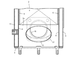
図1乃至図3、及び図5乃至図7を参照して、消音器30の取付け構造を説明する。図1乃至図3、図5に示す如く、ディーゼルエンジン70が排出した排気ガス音を減衰させる消音器30は、耐熱金属材料製の略筒型の消音内側ケース31と、耐熱金属材料製の略筒型の消音外側ケース32と、消音内側ケース31及び消音外側ケース32の右側端部に溶接にて固着した円板状の右側蓋体33とを有する。消音外側ケース32に消音内側ケース31を内設させている。また、円筒形の触媒外側ケース5の直径寸法と、円筒形のフィルタ外側ケース21の直径寸法と、円筒形の消音外側ケース32とが略同一寸法である。円筒形の触媒内側ケース4の直径寸法と、円筒形のフィルタ内側ケース20の直径寸法と、円筒形の消音内側ケース31とが略同一寸法である。なお、円筒形の触媒内側ケース4の直径寸法と、円筒形のフィルタ内側ケース20の直径寸法と、円筒形の消音内側ケース31とが同一寸法でなくてもよい。
The mounting structure of the
図4乃至図7に示す如く、消音内側ケース31及び消音外側ケース32に排気ガス出口管34を貫通させている。排気ガス出口管34の一端側が出口蓋体35によって閉塞されている。消音内側ケース31の内部における排気ガス出口管34の全体に多数の排気孔36が開設されている。消音内側ケース31の内部が、多数の排気孔36を介して、排気ガス出口管34に連通されている。図示しない消音器やテールパイプが排気ガス出口管34の他端側に接続される。
As shown in FIGS. 4 to 7, the exhaust
図6、図7に示す如く、消音内側ケース31には、多数の消音孔37が開設されている。消音内側ケース31の内部が、多数の消音孔37を介して、消音内側ケース31と消音外側ケース32との間に連通されている。消音内側ケース31と消音外側ケース32との間の空間は、右側蓋体33と薄板製支持体38によって閉塞されている。消音内側ケース31と消音外側ケース32との間にセラミックファイバー製消音材39が充填されている。消音内側ケース31の排気ガス移動上流側(左側)の端部が、薄板製支持体38を介して、消音外側ケース32の排気ガス移動上流側(左側)の端部に連結されている。
As shown in FIGS. 6 and 7, the muffler
上記の構成により、消音内側ケース31内から排気ガス出口管34を介して排気ガスが排出される。また、消音内側ケース31の内部において、多数の消音孔37から消音材39に排気ガス音(主に高周波帯の音)が吸音される。排気ガス出口管34の出口側から排出される排気ガスの騒音が減衰される。
With the above configuration, exhaust gas is discharged from the muffler
図1及び図5に示す如く、フィルタ内側ケース20とフィルタ外側ケース21の排気ガス移動下流側(右側)の端部にフィルタ側出口フランジ40を溶接する。消音外側ケース32の排気ガス移動上流側(左側)の端部に、消音側フランジ41を溶接する。フィルタ側出口フランジ40と、消音側フランジ41とを、ボルト42及びナット43によって着脱可能に締結している。なお、フィルタ内側ケース20とフィルタ外側ケース21にセンサ接続プラグ44を固着している。センサ接続プラグ44には、図示しない出口側排気ガス圧力センサや出口側排気ガス温度センサ(サーミスタ)等が接続される。
As shown in FIGS. 1 and 5, the filter
図1、図2、図5乃至図7に示すごとく、ディーゼルエンジン70が排出した排気ガスを浄化するガス浄化フィルタとしてのディーゼル酸化触媒2又はスートフィルタ3と、ディーゼル酸化触媒2又はスートフィルタ3を内設させる内側ケースとしての触媒内側ケース4又はフィルタ内側ケース20と、触媒内側ケース4又はフィルタ内側ケース20を内設させる外側ケースとしての触媒外側ケース5又はフィルタ外側ケース21とを備えてなる排気ガス浄化装置において、ディーゼルエンジン70が排出した排気ガスの排気音を減衰させる排気音減衰体としての消音材39を備え、触媒外側ケース5又はフィルタ外側ケース21の排気ガス出口側端部に消音材39を配置したものであるから、ディーゼル酸化触媒2又はスートフィルタ3の排気ガス浄化機能を維持しながら、ディーゼル酸化触媒2又はスートフィルタ3の構造を変更することなく、排気ガスの消音機能を簡単に付加できる。例えば、前記外側ケースにテールパイプを直接連結させる排気構造や、既設の消音器の消音機能をさらに向上させる排気構造等を容易に構成できる。また、ディーゼル酸化触媒2又はスートフィルタ3部での実施が困難であった排気ガスの高周波低減対策を簡単に実行できる。例えばパンチ孔と繊維状マット等にて形成する消音構造(消音材39)を簡単に設置できる。
As shown in FIGS. 1, 2, 5 to 7, a
図5乃至図7に示すごとく、消音材39を有する消音器30を備え、フィルタ外側ケース21の排気ガス出口側端部に消音器30を着脱可能に連結させるように構成したものであるから、消音器30の着脱によって、ディーゼル酸化触媒2又はスートフィルタ3部における排気ガスの消音機能を簡単に変更できる。
Since the
図5乃至図7に示すごとく、消音材39を有する消音器30を備え、触媒外側ケース5又はフィルタ外側ケース21及び消音器30を略同一外径寸法の円筒形状にそれぞれ形成し、フィルタ外側ケース21の排気ガス出口側端部にリング形状のフランジ体としてのフィルタ側出口フランジ40を設け、フィルタ外側ケース21の排気ガス出口側端部に、フィルタ側出口フランジ40を介して、消音材39を着脱可能に連結させるように構成したものであるから、略同一外径寸法の消音器30がフィルタ側出口フランジ40によってフィルタ外側ケース21に連結されることによって、排気ガスの移動方向に触媒外側ケース5又はフィルタ外側ケース21の取付け寸法を長くするだけで、消音器30をコンパクトに組込むことができる。例えば、ディーゼルエンジン70の排気ガス排出部の側面に接近させて触媒外側ケース5又はフィルタ外側ケース21を簡単に設置できる。また、排気ガスの温度維持によって、ディーゼル酸化触媒2又はスートフィルタ3のガス浄化機能を向上させながら、消音材39の設置によって排気ガスの高周波低減対策を簡単に実行できる。
As shown in FIG. 5 to FIG. 7, a
図5乃至図7に示すごとく、消音材39が内蔵されたサイレンサケーシングとしての消音内側ケース31及び消音外側ケース32と、一端側を閉塞し且つ他端側をテールパイプ(図示省略)に連通させる排気ガス出口管34とを備え、消音内側ケース31及び消音外側ケース32に排気ガス出口管34の排気孔36形成部を貫通させ、フィルタ外側ケース21の排気ガス出口側端部に、フィルタ側出口フランジ40を介して、消音内側ケース31及び消音外側ケース32を着脱可能に連結させるように構成したものであるから、消音内側ケース31及び消音外側ケース32の着脱によって、ディーゼル酸化触媒2又はスートフィルタ3部における排気ガスの消音機能を簡単に変更できる。例えば、消音内側ケース31及び消音外側ケース32とは別に消音器(図示省略)を設置することによって、排気ガスの消音機能をさらに向上させる排気構造等を容易に構成できる。一方、消音材39が内蔵されていない消音内側ケース31及び消音外側ケース32の配置によって、フィルタ外側ケース21にテールパイプ(図示省略)を直接連結させる排気構造を容易に構成できる。また、ディーゼル酸化触媒2又はスートフィルタ3部での実施が困難であった排気ガスの高周波低減対策として、消音内側ケース31及び消音外側ケース32内に、消音材39(パンチ孔と繊維状マット等)消音構造を簡単に構成できる。
As shown in FIGS. 5 to 7, the silencer
図5乃至図7に示すごとく、前記サイレンサケーシングは、円筒形状の消音内側ケース31と円筒形状の消音外側ケース32を有し、消音外側ケース32内に消音内側ケース31を配置させ、消音内側ケース31と消音外側ケース32の間に消音材39を充填させ、消音内側ケース31に多数の消音孔37を形成したものであるから、ディーゼル酸化触媒2又はスートフィルタ3を内設させる触媒内側ケース4又はフィルタ内側ケース20や触媒外側ケース5又はフィルタ外側ケース21を備えた排気ガス浄化構造に近似させて、前記サイレンサケーシング(消音内側ケース31や消音外側ケース32)を構成できる。ディーゼル酸化触媒2又はスートフィルタ3を内設させるための触媒内側ケース4又はフィルタ内側ケース20や触媒外側ケース5又はフィルタ外側ケース21と同一材料(パイプ等)を利用して、前記サイレンサケーシングの消音内側ケース31や消音外側ケース32を形成できる。前記サイレンサケーシングの製造コストを簡単に低減できる。
As shown in FIGS. 5 to 7, the silencer casing has a cylindrical silencer
図10乃至図14を参照して、排気ガス流入口12の変形構造を説明する。上記実施形態において、図9に示す如く、排気ガス流入口12は、触媒内側ケース4及び触媒外側ケース5に略楕円形の貫通孔を開設することによって形成していた。図10に示す如く、触媒内側ケース4及び触媒外側ケース5に略四角形の貫通孔を開設することによって排気ガス流入口12を形成できる。また、図11に示す如く、触媒内側ケース4及び触媒外側ケース5に略長円形の貫通孔を開設することによって排気ガス流入口12を形成できる。また、図12に示す如く、触媒内側ケース4及び触媒外側ケース5に略多角形の貫通孔を開設することによって排気ガス流入口12を形成できる。また、図13に示す如く、触媒内側ケース4及び触媒外側ケース5に略六角形の貫通孔を開設することによって排気ガス流入口12を形成できる。また、図14に示す如く、触媒内側ケース4及び触媒外側ケース5に不定形の貫通孔を開設することによって排気ガス流入口12を形成できる。
A modified structure of the
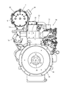
図15乃至図18を参照して、ディーゼルエンジン70に前記DPF1を設けた構造を説明する。図15乃至図18に示す如く、ディーゼルエンジン70のシリンダヘッド72の左右側面に、排気マニホールド71と、吸気マニホールド73とが配置されている。シリンダヘッド72は、エンジン出力軸74(クランク軸)とピストン(図示省略)を有するシリンダブロック75に上載される。シリンダブロック75の前面と後面からエンジン出力軸74の前端と後端を突出させる。シリンダブロック75の前面に冷却ファン76を設ける。エンジン出力軸74の前端側からVベルト77を介して冷却ファン76に回転力を伝達するように構成している。
With reference to FIG. 15 thru | or FIG. 18, the structure which provided the said DPF1 in the
また、図18に示す如く、シリンダブロック75の後面にフライホイールハウジング78を固着している。フライホイールハウジング78にフライホイール79を内設する。エンジン出力軸74の後端側にフライホイール79を軸支させている。後述するバックホウ100やフォークリフト120等の作動部に、フライホイール79を介してディーゼルエンジン70の動力を取出すように構成している。また、図15に示す如く、シリンダヘッド72に支持脚体19をボルト80にて着脱可能に締結している。上記したDPF1は、支持脚体19を介して、高剛性のシリンダヘッド72に支持されるように構成している。
Further, as shown in FIG. 18, a
図19及び図20を参照して、バックホウ100に前記ディーゼルエンジン70を搭載した構造を説明する。図19及び図20に示す如く、バックホウ100は、左右一対の走行クローラ103を有する履帯式の走行装置102と、走行装置102上に設けられた旋回機体104とを備えている。旋回機体104は、図示しない旋回用油圧モータによって、360°の全方位にわたって水平旋回可能に構成されている。走行装置102の後部には、対地作業用の土工板105が昇降動可能に装着されている。旋回機体104の左側部には、操縦部106とディーゼルエンジン70とが搭載されている。旋回機体104の右側部には、掘削作業のためのブーム111及びバケット113を有する作業部110が設けられている。
A structure in which the
操縦部106には、オペレータが着座する操縦座席108と、ディーゼルエンジン70等を出力操作する操作手段や、作業部110用の操作手段としてのレバー又はスイッチ等が配置されている。作業部110の構成要素であるブーム111には、ブームシリンダ112とバケットシリンダ114とが配置されている。ブーム111の先端部には、掘削用アタッチメントとしてのバケット113が、掬い込み回動可能に枢着されている。ブームシリンダ112又はバケットシリンダ114を作動させて、バケット113によって土工作業(作溝等の対地作業)を実行するように構成している。
The
図21及び図22を参照して、フォークリフトカー120に前記ディーゼルエンジン70を搭載した構造を説明する。図21及び図22に示す如く、フォークリフトカー120は、左右一対の前輪122及び後輪123を有する走行機体124を備えている。走行機体124には、操縦部125とディーゼルエンジン70とが搭載されている。走行機体124の前側部には、荷役作業のためのフォーク126を有する作業部127が設けられている。操縦部125には、オペレータが着座する操縦座席128と、操縦ハンドル129と、ディーゼルエンジン70等を出力操作する操作手段や、作業部127用の操作手段としてのレバー又はスイッチ等が配置されている。
A structure in which the
作業部127の構成要素であるマスト130には、フォーク126が昇降可能に配置されている。フォーク126を昇降動させて、荷物を積んだパレット(図示省略)をフォーク126に上載させ、走行機体124を前後進移動させて、前記パレットの運搬等の荷役作業を実行するように構成している。
A
2 ディーゼル酸化触媒(ガス浄化フィルタ)
3 スートフィルタ(ガス浄化フィルタ)
4 触媒内側ケース
5 触媒外側ケース
12 排気ガス流入口
16 排気ガス入口管
20 フィルタ内側ケース
21 フィルタ外側ケース
70 ディーゼルエンジン
2 Diesel oxidation catalyst (gas purification filter)
3 Soot filter (gas purification filter)
4 catalyst
Claims (4)
前記内側ケース及び前記外側ケースの一端側の周面に排気ガス入口を形成し、前記外側ケースの外周のうち前記排気ガス入口の外側に入口管を配置し、前記入口管の排気ガス入口側の開口端面の面積よりも、前記入口管の排気ガス出口側の開口端面の面積を大きく形成し、
前記外側ケースの排気ガス移動方向で、前記外側ケース及び前記内側ケースの排気ガス入口の開口寸法よりも、前記入口管の排気ガス出口側の開口寸法を大きく形成している、
排気ガス浄化装置。 In an exhaust gas purifying apparatus comprising a gas purification filter for purifying exhaust gas discharged from an engine, an inner case for installing the gas purification filter, and an outer case for installing the inner case,
An exhaust gas inlet is formed on a peripheral surface of one end side of the inner case and the outer case, an inlet pipe is disposed outside the exhaust gas inlet in an outer periphery of the outer case, and an exhaust pipe inlet side of the inlet pipe is disposed. Forming the area of the opening end face on the exhaust gas outlet side of the inlet pipe larger than the area of the opening end face ;
In the exhaust gas movement direction of the outer case, the opening size on the exhaust gas outlet side of the inlet pipe is larger than the opening size of the exhaust gas inlet of the outer case and the inner case.
Exhaust gas purification device.
請求項1に記載の排気ガス浄化装置。 The exhaust gas movement upstream end surface of the gas purification filter is disposed on the exhaust gas movement upstream side of the outer case with respect to the exhaust gas movement downstream side end portion of the inlet pipe on the exhaust pipe outlet side. Composing,
The exhaust gas purification apparatus according to claim 1.
請求項1に記載の排気ガス浄化装置。 Of the opening edge of the exhaust gas inlet of the outer case, it is configured to connect the end of the inlet pipe on the exhaust gas outlet side to the opening edge of the exhaust gas inlet upstream of the exhaust gas movement.
The exhaust gas purification apparatus according to claim 1.
請求項1に記載の排気ガス浄化装置。 The opening shape of the exhaust gas inlet of the outer case and the inner case is formed into an ellipse or a polygonal shape having a short diameter in the exhaust gas moving direction and a long diameter in a direction intersecting the exhaust gas moving direction,
The exhaust gas purification apparatus according to claim 1.
Priority Applications (1)
| Application Number | Priority Date | Filing Date | Title |
|---|---|---|---|
| JP2008240368A JP4963304B2 (en) | 2008-09-19 | 2008-09-19 | Exhaust gas purification device |
Applications Claiming Priority (1)
| Application Number | Priority Date | Filing Date | Title |
|---|---|---|---|
| JP2008240368A JP4963304B2 (en) | 2008-09-19 | 2008-09-19 | Exhaust gas purification device |
Related Child Applications (1)
| Application Number | Title | Priority Date | Filing Date |
|---|---|---|---|
| JP2012041888A Division JP5443530B2 (en) | 2012-02-28 | 2012-02-28 | Exhaust gas purification device |
Publications (3)
| Publication Number | Publication Date |
|---|---|
| JP2010071207A JP2010071207A (en) | 2010-04-02 |
| JP2010071207A5 JP2010071207A5 (en) | 2011-01-20 |
| JP4963304B2 true JP4963304B2 (en) | 2012-06-27 |
Family
ID=42203222
Family Applications (1)
| Application Number | Title | Priority Date | Filing Date |
|---|---|---|---|
| JP2008240368A Active JP4963304B2 (en) | 2008-09-19 | 2008-09-19 | Exhaust gas purification device |
Country Status (1)
| Country | Link |
|---|---|
| JP (1) | JP4963304B2 (en) |
Families Citing this family (5)
| Publication number | Priority date | Publication date | Assignee | Title |
|---|---|---|---|---|
| JP5551497B2 (en) * | 2010-04-09 | 2014-07-16 | ヤンマー株式会社 | Exhaust gas purification device |
| JP5279753B2 (en) | 2010-04-15 | 2013-09-04 | Udトラックス株式会社 | Exhaust purification device |
| JP5649896B2 (en) * | 2010-09-29 | 2015-01-07 | ヤンマー株式会社 | Engine equipment |
| KR20130079035A (en) * | 2012-01-02 | 2013-07-10 | 볼보 컨스트럭션 이큅먼트 에이비 | Cover of diesel particulate filter |
| JP5955243B2 (en) * | 2013-02-19 | 2016-07-20 | ヤンマー株式会社 | Engine equipment |
Family Cites Families (4)
| Publication number | Priority date | Publication date | Assignee | Title |
|---|---|---|---|---|
| JPS49105734U (en) * | 1972-12-29 | 1974-09-10 | ||
| GB2381220B (en) * | 2001-10-25 | 2004-01-14 | Eminox Ltd | Gas treatment apparatus |
| GB2387339B (en) * | 2002-04-13 | 2004-02-25 | Eminox Ltd | Gas treatment apparatus |
| JP2008106663A (en) * | 2006-10-25 | 2008-05-08 | Yanmar Co Ltd | Exhaust emission control device in internal combustion engine |
-
2008
- 2008-09-19 JP JP2008240368A patent/JP4963304B2/en active Active
Also Published As
| Publication number | Publication date |
|---|---|
| JP2010071207A (en) | 2010-04-02 |
Similar Documents
| Publication | Publication Date | Title |
|---|---|---|
| JP5185751B2 (en) | Exhaust gas purification device | |
| JP5285366B2 (en) | Engine equipment | |
| WO2010032647A1 (en) | Engine device | |
| JP2010071184A5 (en) | ||
| WO2010032648A1 (en) | Engine device | |
| JP4963304B2 (en) | Exhaust gas purification device | |
| JP2010071207A5 (en) | ||
| JP5164762B2 (en) | Exhaust gas purification device | |
| JP5580392B2 (en) | Engine equipment | |
| JP5285369B2 (en) | Engine equipment | |
| JP5285368B2 (en) | Engine equipment | |
| JP2010071182A (en) | Exhaust emission control device | |
| JP2010071208A5 (en) | ||
| JP5923543B2 (en) | Exhaust gas purification device | |
| JP5509258B2 (en) | Engine equipment | |
| JP5235575B2 (en) | Exhaust gas purification device | |
| JP5231146B2 (en) | Exhaust gas purification device | |
| JP5525086B2 (en) | Exhaust gas purification device | |
| JP5443530B2 (en) | Exhaust gas purification device | |
| JP5793212B2 (en) | Engine equipment | |
| JP2015108377A (en) | Engine device | |
| JP5285370B2 (en) | Engine equipment | |
| JP5632508B2 (en) | Engine equipment | |
| JP5654520B2 (en) | Engine equipment | |
| JP2013189986A (en) | Engine device |
Legal Events
| Date | Code | Title | Description |
|---|---|---|---|
| A521 | Written amendment |
Free format text: JAPANESE INTERMEDIATE CODE: A523 Effective date: 20101130 |
|
| A621 | Written request for application examination |
Free format text: JAPANESE INTERMEDIATE CODE: A621 Effective date: 20101130 |
|
| A977 | Report on retrieval |
Free format text: JAPANESE INTERMEDIATE CODE: A971007 Effective date: 20111115 |
|
| A131 | Notification of reasons for refusal |
Free format text: JAPANESE INTERMEDIATE CODE: A131 Effective date: 20120110 |
|
| A521 | Written amendment |
Free format text: JAPANESE INTERMEDIATE CODE: A523 Effective date: 20120228 |
|
| TRDD | Decision of grant or rejection written | ||
| A01 | Written decision to grant a patent or to grant a registration (utility model) |
Free format text: JAPANESE INTERMEDIATE CODE: A01 Effective date: 20120321 |
|
| A01 | Written decision to grant a patent or to grant a registration (utility model) |
Free format text: JAPANESE INTERMEDIATE CODE: A01 |
|
| A61 | First payment of annual fees (during grant procedure) |
Free format text: JAPANESE INTERMEDIATE CODE: A61 Effective date: 20120322 |
|
| R150 | Certificate of patent or registration of utility model |
Ref document number: 4963304 Country of ref document: JP Free format text: JAPANESE INTERMEDIATE CODE: R150 Free format text: JAPANESE INTERMEDIATE CODE: R150 |
|
| FPAY | Renewal fee payment (event date is renewal date of database) |
Free format text: PAYMENT UNTIL: 20150406 Year of fee payment: 3 |
|
| S531 | Written request for registration of change of domicile |
Free format text: JAPANESE INTERMEDIATE CODE: R313531 |
|
| R350 | Written notification of registration of transfer |
Free format text: JAPANESE INTERMEDIATE CODE: R350 |
|
| R250 | Receipt of annual fees |
Free format text: JAPANESE INTERMEDIATE CODE: R250 |
|
| S533 | Written request for registration of change of name |
Free format text: JAPANESE INTERMEDIATE CODE: R313533 |
|
| R350 | Written notification of registration of transfer |
Free format text: JAPANESE INTERMEDIATE CODE: R350 |