JP5267618B2 - Information processing device - Google Patents
Information processing device Download PDFInfo
- Publication number
- JP5267618B2 JP5267618B2 JP2011140286A JP2011140286A JP5267618B2 JP 5267618 B2 JP5267618 B2 JP 5267618B2 JP 2011140286 A JP2011140286 A JP 2011140286A JP 2011140286 A JP2011140286 A JP 2011140286A JP 5267618 B2 JP5267618 B2 JP 5267618B2
- Authority
- JP
- Japan
- Prior art keywords
- data
- altitude
- unit
- information processing
- processing apparatus
- Prior art date
- Legal status (The legal status is an assumption and is not a legal conclusion. Google has not performed a legal analysis and makes no representation as to the accuracy of the status listed.)
- Expired - Fee Related
Links
- 230000010365 information processing Effects 0.000 title claims 19
- 230000001133 acceleration Effects 0.000 claims description 51
- 230000008859 change Effects 0.000 claims description 46
- 238000001514 detection method Methods 0.000 claims description 28
- 230000007423 decrease Effects 0.000 claims description 3
- 238000012937 correction Methods 0.000 description 56
- 230000006870 function Effects 0.000 description 46
- 238000004364 calculation method Methods 0.000 description 40
- 238000000034 method Methods 0.000 description 22
- 238000004891 communication Methods 0.000 description 18
- 238000012545 processing Methods 0.000 description 16
- 238000010586 diagram Methods 0.000 description 13
- 230000005540 biological transmission Effects 0.000 description 11
- 230000008569 process Effects 0.000 description 11
- 230000000737 periodic effect Effects 0.000 description 5
- 238000005070 sampling Methods 0.000 description 5
- 230000005236 sound signal Effects 0.000 description 4
- 238000004590 computer program Methods 0.000 description 3
- 239000000203 mixture Substances 0.000 description 3
- 230000003287 optical effect Effects 0.000 description 3
- 238000006243 chemical reaction Methods 0.000 description 2
- 239000000284 extract Substances 0.000 description 2
- 235000019577 caloric intake Nutrition 0.000 description 1
- 230000001413 cellular effect Effects 0.000 description 1
- 238000005401 electroluminescence Methods 0.000 description 1
- 238000005516 engineering process Methods 0.000 description 1
- 230000001678 irradiating effect Effects 0.000 description 1
- 239000004973 liquid crystal related substance Substances 0.000 description 1
- 238000012986 modification Methods 0.000 description 1
- 230000004048 modification Effects 0.000 description 1
- 230000009467 reduction Effects 0.000 description 1
- 230000008054 signal transmission Effects 0.000 description 1
- 238000012549 training Methods 0.000 description 1
- XLYOFNOQVPJJNP-UHFFFAOYSA-N water Substances O XLYOFNOQVPJJNP-UHFFFAOYSA-N 0.000 description 1
Images


Classifications
-
- G—PHYSICS
- G01—MEASURING; TESTING
- G01C—MEASURING DISTANCES, LEVELS OR BEARINGS; SURVEYING; NAVIGATION; GYROSCOPIC INSTRUMENTS; PHOTOGRAMMETRY OR VIDEOGRAMMETRY
- G01C21/00—Navigation; Navigational instruments not provided for in groups G01C1/00 - G01C19/00
- G01C21/10—Navigation; Navigational instruments not provided for in groups G01C1/00 - G01C19/00 by using measurements of speed or acceleration
- G01C21/12—Navigation; Navigational instruments not provided for in groups G01C1/00 - G01C19/00 by using measurements of speed or acceleration executed aboard the object being navigated; Dead reckoning
- G01C21/16—Navigation; Navigational instruments not provided for in groups G01C1/00 - G01C19/00 by using measurements of speed or acceleration executed aboard the object being navigated; Dead reckoning by integrating acceleration or speed, i.e. inertial navigation
- G01C21/183—Compensation of inertial measurements, e.g. for temperature effects
- G01C21/188—Compensation of inertial measurements, e.g. for temperature effects for accumulated errors, e.g. by coupling inertial systems with absolute positioning systems
-
- A—HUMAN NECESSITIES
- A61—MEDICAL OR VETERINARY SCIENCE; HYGIENE
- A61B—DIAGNOSIS; SURGERY; IDENTIFICATION
- A61B5/00—Measuring for diagnostic purposes; Identification of persons
- A61B5/103—Detecting, measuring or recording devices for testing the shape, pattern, colour, size or movement of the body or parts thereof, for diagnostic purposes
- A61B5/11—Measuring movement of the entire body or parts thereof, e.g. head or hand tremor, mobility of a limb
-
- G—PHYSICS
- G01—MEASURING; TESTING
- G01C—MEASURING DISTANCES, LEVELS OR BEARINGS; SURVEYING; NAVIGATION; GYROSCOPIC INSTRUMENTS; PHOTOGRAMMETRY OR VIDEOGRAMMETRY
- G01C21/00—Navigation; Navigational instruments not provided for in groups G01C1/00 - G01C19/00
- G01C21/26—Navigation; Navigational instruments not provided for in groups G01C1/00 - G01C19/00 specially adapted for navigation in a road network
- G01C21/34—Route searching; Route guidance
- G01C21/3453—Special cost functions, i.e. other than distance or default speed limit of road segments
-
- G—PHYSICS
- G01—MEASURING; TESTING
- G01C—MEASURING DISTANCES, LEVELS OR BEARINGS; SURVEYING; NAVIGATION; GYROSCOPIC INSTRUMENTS; PHOTOGRAMMETRY OR VIDEOGRAMMETRY
- G01C21/00—Navigation; Navigational instruments not provided for in groups G01C1/00 - G01C19/00
- G01C21/38—Electronic maps specially adapted for navigation; Updating thereof
- G01C21/3804—Creation or updating of map data
- G01C21/3807—Creation or updating of map data characterised by the type of data
- G01C21/3815—Road data
- G01C21/3822—Road feature data, e.g. slope data
-
- G—PHYSICS
- G06—COMPUTING; CALCULATING OR COUNTING
- G06F—ELECTRIC DIGITAL DATA PROCESSING
- G06F17/00—Digital computing or data processing equipment or methods, specially adapted for specific functions
Landscapes
- Engineering & Computer Science (AREA)
- Radar, Positioning & Navigation (AREA)
- Remote Sensing (AREA)
- Physics & Mathematics (AREA)
- General Physics & Mathematics (AREA)
- Automation & Control Theory (AREA)
- Health & Medical Sciences (AREA)
- Life Sciences & Earth Sciences (AREA)
- Theoretical Computer Science (AREA)
- Heart & Thoracic Surgery (AREA)
- Public Health (AREA)
- Biophysics (AREA)
- Pathology (AREA)
- Biomedical Technology (AREA)
- Dentistry (AREA)
- Medical Informatics (AREA)
- Molecular Biology (AREA)
- Surgery (AREA)
- Animal Behavior & Ethology (AREA)
- General Health & Medical Sciences (AREA)
- Oral & Maxillofacial Surgery (AREA)
- Veterinary Medicine (AREA)
- Data Mining & Analysis (AREA)
- Databases & Information Systems (AREA)
- Mathematical Physics (AREA)
- Software Systems (AREA)
- General Engineering & Computer Science (AREA)
- Physiology (AREA)
- Navigation (AREA)
- Instructional Devices (AREA)
- Processing Or Creating Images (AREA)
Description
本発明は、標高推定装置、標高推定方法およびプログラムに関する。 The present invention relates to an altitude estimation device, an altitude estimation method, and a program.
昨今、カーナビゲーションシステムに代表されるナビゲーションシステムが普及している。カーナビゲーションシステムは、自動車の走行時に現在位置の表示や目的地への経路案内を行う。現在位置の表示や目的地への経路案内は、通常、ナビゲーション端末の画面に表示される地図上で行われる。また、経路案内が音声で行なわれることもある。 In recent years, navigation systems represented by car navigation systems have become widespread. The car navigation system displays the current position and provides route guidance to a destination when the automobile is running. The display of the current position and the route guidance to the destination are usually performed on a map displayed on the screen of the navigation terminal. In addition, route guidance may be performed by voice.
ナビゲーションシステムの一例として、近年は自転車や徒歩用のナビゲーション端末も知られている。自転車や徒歩用のナビゲーション端末は、地図データに加えて標高データも参照することで、勾配が緩やかな道を優先した経路案内などを行うことができる。ここで、標高データは、例えば特許文献1に記載されているように、航空機や人工衛星など上空から撮像した複数の画像からステレオ画像処理により取得されたり、レーザプロファイラを使用して航空機や衛星からレーザを照射することで各地点の位置、標高を測定する方法により取得されたりする。
In recent years, navigation terminals for bicycles and walking are also known as examples of navigation systems. Bicycle and walking navigation terminals can refer to altitude data in addition to map data to provide route guidance that prioritizes roads with gentle slopes. Here, the altitude data is acquired by stereo image processing from a plurality of images taken from above, such as an aircraft or an artificial satellite, as described in
しかし、上記方法で取得される標高データは、実際の標高と異なる場合がある。 However, the altitude data acquired by the above method may be different from the actual altitude.
そこで、本開示では標高データの精度を向上することが可能な、新規かつ改良された標高推定装置、標高推定方法およびプログラムを提案する。 Therefore, the present disclosure proposes a new and improved altitude estimation apparatus, altitude estimation method, and program capable of improving the accuracy of altitude data.
本開示によれば、移動経路においてセンサにより検知される検知情報を用いて前記移動経路上の位置の標高データを推定する推定部と、前記移動経路上の位置と関連付けて設定されている標高データを、前記推定部により推定された標高データに基づき補正する補正部と、を備える標高推定装置を提供する。 According to the present disclosure, the estimation unit that estimates the elevation data of the position on the movement route using the detection information detected by the sensor in the movement route, and the elevation data set in association with the position on the movement route An altitude estimation apparatus comprising: a correction unit that corrects the image based on altitude data estimated by the estimation unit.
また、本開示によれば、移動経路においてセンサにより検知される前記移動経路の標高に関する検知情報に基づき、前記移動経路上の位置の標高データを推定することと、前記移動経路上の位置と関連付けて設定されている標高データを、前記推定部により推定された標高データに基づき補正することと、を含む標高推定方法を提供する。 Further, according to the present disclosure, the elevation data of the position on the movement route is estimated based on the detection information related to the elevation of the movement route detected by the sensor on the movement route, and the position is associated with the position on the movement route. And correcting the set altitude data based on the altitude data estimated by the estimation unit.
また、本開示によれば、コンピュータを、移動経路においてセンサにより検知される前記移動経路の標高に関する検知情報に基づき、前記移動経路上の位置の標高データを推定する標高推定部と、前記移動経路上の位置と関連付けて設定されている標高データを、前記推定部により推定された標高データに基づき補正する補正部と、として機能させるためのプログラムを提供する。 Further, according to the present disclosure, an elevation estimation unit that estimates elevation data of a position on the movement route based on detection information related to the elevation of the movement route detected by a sensor in the movement route, and the movement route There is provided a program for causing altitude data set in association with an upper position to function as a correction unit that corrects altitude data based on the altitude data estimated by the estimation unit.
以上説明したように本開示によれば、標高データの精度を向上することができる。 As described above, according to the present disclosure, the accuracy of altitude data can be improved.
以下に添付図面を参照しながら、本開示の好適な実施の形態について詳細に説明する。なお、本明細書及び図面において、実質的に同一の機能構成を有する構成要素については、同一の符号を付することにより重複説明を省略する。 Hereinafter, preferred embodiments of the present disclosure will be described in detail with reference to the accompanying drawings. In addition, in this specification and drawing, about the component which has the substantially same function structure, duplication description is abbreviate | omitted by attaching | subjecting the same code | symbol.
また、以下に示す項目順序に従って本開示を説明する。
1.第1の実施形態
2.第2の実施形態
3.第3の実施形態
4.まとめ
Moreover, this indication is demonstrated according to the item order shown below.
1. First embodiment2. Second embodiment 3. 3. Third embodiment Summary
ここで説明する本開示による技術は、上記項目の「1.第1の実施形態」〜「3.第3の実施形態」のように、多様な形態で実施され得る。また、各実施形態によるナビゲーション端末10−2、10−3または標高推定サーバ60は、
(1)移動経路においてセンサにより検知される検知情報を用いて前記移動経路上の位置の標高データを推定する推定部(標高推定部620、標高推定部151)と、
(2)前記移動経路上の位置と関連付けて設定されている標高データを、前記推定部により推定された標高データに基づき補正する補正部(標高補正部630、標高補正部152)と、
を備える、標高推定装置である。
The technology according to the present disclosure described here can be implemented in various forms such as “1. First embodiment” to “3. Third embodiment” of the above item. In addition, the navigation terminals 10-2, 10-3 or the
(1) an estimation unit (
(2) a correction unit (
Is an altitude estimation apparatus.
<1.第1の実施形態>
第1の実施形態では、本開示による標高推定装置を標高推定サーバ60に適用する。また、移動端末としてナビゲーション端末10−1を用いる。以下、標高推定サーバ60とナビゲーション端末10−1から成る第1の実施形態によるナビゲーションシステムについて説明する。
<1. First Embodiment>
In the first embodiment, the altitude estimation apparatus according to the present disclosure is applied to the
[1−1.ナビゲーションシステムの概要]
(全体構成)
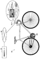
図1は、第1の実施形態によるナビゲーションシステムの全体構成を示す図である。図1に示すように、第1の実施形態によるナビゲーションシステムは、自転車50に取り付けられたナビゲーション端末10−1と、標高推定サーバ60とを有し、ナビゲーション端末10−1と標高推定サーバ60はネットワーク40を介して接続される。
[1-1. Overview of navigation system]
(overall structure)
FIG. 1 is a diagram showing an overall configuration of a navigation system according to the first embodiment. As shown in FIG. 1, the navigation system according to the first embodiment includes a navigation terminal 10-1 attached to a
ナビゲーション端末10−1は、図1に示すように、例えばPND(Personal Navigation Device)により実現される。また、ナビゲーション端末10−1は、図1に示すように、自転車用のクレードル13により自転車50のハンドル51に取り付けられる。取り付けられる位置は、ユーザが自転車50に乗って走行しているときにナビゲーション端末10−1の表示部12を見るための視線移動がより少ない位置がよい。
As illustrated in FIG. 1, the navigation terminal 10-1 is realized by, for example, PND (Personal Navigation Device). Further, as shown in FIG. 1, the navigation terminal 10-1 is attached to the
ナビゲーション端末10−1は、目的地までの経路を案内するナビゲーション機能を有する。例えば、ナビゲーション端末10−1は、自転車50で走行する場合に都合のよい道を選択して経路を案内することができる。また、ナビゲーション端末10−1は、自動車などの車両では通ることのできない道を案内する経路の候補として経路探索することができる。さらに、ナビゲーション端末10−1は、自転車の走行スピード、走行距離、及び消費カロリーなどの情報を表示することもできる。なお、ナビゲーション端末10−1は、自転車走行用の経路案内を行う自転車モードの他、車載モード、及び徒歩モードの複数の動作モードを有してもよい。
The navigation terminal 10-1 has a navigation function for guiding a route to a destination. For example, the navigation terminal 10-1 can select a route that is convenient when traveling on a
また、本実施形態によるナビゲーション端末10−1は、走行中に検知したセンサ情報を標高推定サーバ60に出力し、また、標高推定サーバ60において補正された標高データを取得することができる。
In addition, the navigation terminal 10-1 according to the present embodiment can output sensor information detected during traveling to the
(ナビゲーション端末の外観)
次に、図2を参照して、ナビゲーション端末10−1の外観について説明する。図2は、情報提供画面を表示するナビゲーション端末10−1の外観図である。図2に示すように、ナビゲーション端末10−1は、自転車のハンドルに取り付け可能なクレードル13によってその筐体が自転車に保持される。ナビゲーション端末10−1は、クレードル13に容易に取付けることができるとともに、取り外すことも可能である。
(Appearance of navigation terminal)
Next, the external appearance of the navigation terminal 10-1 will be described with reference to FIG. FIG. 2 is an external view of the navigation terminal 10-1 that displays the information providing screen. As shown in FIG. 2, the casing of the navigation terminal 10-1 is held on the bicycle by a
また、ナビゲーション端末10−1は、その前面に各種の情報を提供する情報提供画面を含む画像を表示する表示部12を有する。ナビゲーション端末10−1は、ナビゲーション端末10−1自身の現在の位置情報を取得する機能を有するとともに、標高推定サーバ60から取得した地図データおよび標高データを記憶している。このため、ナビゲーション端末10−1は、図2に示すように、地図上に現在位置の情報を重畳した地図画面121と、経路の標高変化をグラフ表示した標高画面122を、表示部12に表示することができる。
Moreover, the navigation terminal 10-1 has the
(情報提供画面について)
次に、図3を参照して、本実施形態によるナビゲーション端末10−1に表示される情報提供画面について説明する。図3は、ナビゲーション端末10−1に表示される情報提供画面の他の例を示す図である。図3に示すように、情報提供画面は、地図画面121と標高画面122から成る。
(About the information provision screen)
Next, with reference to FIG. 3, the information provision screen displayed on the navigation terminal 10-1 by this embodiment is demonstrated. FIG. 3 is a diagram illustrating another example of the information providing screen displayed on the navigation terminal 10-1. As shown in FIG. 3, the information providing screen includes a
地図画面121は、地図上に、経路案内情報表示210、および自転車アイコン211が重畳表示された画面である。ナビゲーション端末10−1は、地図画面121を利用してルート案内を行う。また、図3に示す自転車アイコン211を囲む円上に表示される矢印212は、目的地の方角を示す。
The
また、標高画面122は、現在位置アイコン213、標高の変化を示す標高グラフ215、および勾配情報表示217を含む。標高グラフ215を示すことにより、ナビゲーション端末10−1は、これから走る道が平坦なのか上り下りが激しいのかについてユーザに情報提供することができる。また、図3に示す勾配情報表示217は、これから勾配1%の上り坂が408m続くことを示す。このような標高画面122は、標高データに基づいて生成される。
Further, the
ここで、標高データは、予めレーザ測量や画像測量などによって取得されるところ、橋や高架などの建造物の高さが正しく算出されてない場合がある。例えば、図4に示すように、川に架かる橋の標高データとして、誤って水面の高さが算出されてしまう場合がある。この場合、実際はアーチ状の勾配を有する橋が、ナビゲーション端末10−1では平坦な道として標高画面や3D地図画面に表示されるので、ユーザは違和感が覚える。また、実際の標高と標高データが異なる場合、ナビゲーション端末10−1が勾配に応じた経路探索を正確に行うことは困難である。 Here, altitude data is acquired in advance by laser surveying, image surveying, or the like, but the height of a building such as a bridge or an overhead may not be calculated correctly. For example, as shown in FIG. 4, the height of the water surface may be erroneously calculated as the elevation data of the bridge over the river. In this case, the bridge having an arch-like gradient is actually displayed on the elevation screen or the 3D map screen as a flat road on the navigation terminal 10-1, so that the user feels uncomfortable. In addition, when the actual altitude and the altitude data are different, it is difficult for the navigation terminal 10-1 to accurately perform a route search according to the gradient.
そこで、本実施形態によるナビゲーションシステムでは、実際に走行中にナビゲーション端末10−1が取得したセンサ情報に基づいて標高推定サーバ60が標高データを補正することにより、標高データの精度を向上させる。
Therefore, in the navigation system according to the present embodiment, the
以上、本実施形態によるナビゲーションシステムの概要について説明した。続いて、ナビゲーションシステムを構成するナビゲーション端末10−1と、標高推定サーバ60についてそれぞれ説明する。
The overview of the navigation system according to this embodiment has been described above. Next, the navigation terminal 10-1 and the
[1−2.ナビゲーション端末の構成]
図5は、本実施形態によるナビゲーション端末10−1の構成を示すブロック図である。図5に示すように、ナビゲーション端末10−1は、表示部12、記憶部102、操作部104、音声出力部106、接続インタフェース108、通信部109、およびナビゲーション機能ユニット110を主に備える。
[1-2. Configuration of navigation terminal]
FIG. 5 is a block diagram showing the configuration of the navigation terminal 10-1 according to the present embodiment. As shown in FIG. 5, the navigation terminal 10-1 mainly includes a
ナビゲーション機能ユニット110は、GPSアンテナ112、Z軸ジャイロセンサ114、Y軸ジャイロセンサ115、3軸加速度センサ116、地磁気センサ117、気圧センサ118、GPS処理部132、角度算出部134、位置算出部136、速度算出部138、姿勢角検出部140、方位算出部142、高度算出部144、および制御部150を備える。ここで、図5に示すナビゲーション端末10−1は、各種センサ(GPSアンテナ112、Z軸ジャイロセンサ114、Y軸ジャイロセンサ115、3軸加速度センサ116、地磁気センサ117、および気圧センサ118)を有するが、本開示によるナビゲーション端末は図5に示す構成に限定されず、各種センサのうち少なくとも一つのセンサを有する構成であってもよい。
The
表示部12は、例えば、地図データに現在位置を示す情報を重畳した画面を出力する表示装置である。この表示部12は、例えば、液晶ディスプレイ(LCD:Liquid Crystal Display)、有機EL(Electroluminescence)ディスプレイなどの表示装置であってもよい。
The
記憶部102は、ナビゲーション端末10−1が動作するためのプログラムや、地図データ、標高データなどを記憶する記憶媒体である。本実施形態による記憶部102は、標高推定サーバ60から取得した地図データおよび標高データを記憶する。
The
なお、この記憶部102は、例えば、Flash ROM(又はFlash Memory)、EEPROM(Electrically Erasable Programmable Read−Only Memory)、EPROM(Erasable Programmable ROM)などの不揮発性メモリ、ハードディスクおよび円盤型磁性体ディスクなどの磁気ディスク、CD(Compact Disc)、DVD−R(Digital Versatile Disc Recordable)およびBD(Blu−Ray Disc(登録商標))などの光ディスク、並びに、MO(Magneto Optical)ディスクなどの記憶媒体であってもよい。
The
操作部104は、ユーザによる操作指示を受付け、その操作内容をナビゲーション機能ユニット110に出力する。ユーザによる操作指示としては、例えば、目的地の設定、地図の拡大および縮小、音声案内設定、画面表示設定などが挙げられる。この操作部104は、表示部12と一体的に設けられるタッチスクリーンであってもよい。或いは、操作部104は、ボタン、スイッチ、およびレバーなど、表示部12と分離して設けられる物理的構成であってもよい。また、操作部104は、リモートコントローラから送信されたユーザによる操作指示を示す信号を検出する信号受信部であってもよい。
The
音声出力部106は、音声データを出力する出力装置であり、例えば、スピーカ、イヤホン、またはヘッドホンなどであってよい。この音声出力部106は、例えば、ナビゲーションにかかる音声ガイダンスを出力する。ユーザは、この音声ガイダンスを聞くことにより表示部12を見なくても進むべき経路を知ることができる。また、本実施形態による音声出力部106は、自転車50がこれから走行する経路の勾配情報を音声により出力することもできる。
The
接続インタフェース部108は、スピードセンサ72及びケイデンスセンサ70と接続するためのインタフェースである。接続インタフェース部108は、スピードセンサ72が出力するスピードパルス信号を受信し、受信した情報を制御部150に入力する。また、接続インタフェース部108は、ケイデンスセンサ70が出力するケイデンスパルス信号を受信し、受信した情報を制御部150に入力する。
The
通信部109は、標高推定サーバ60とのインタフェースであり、標高推定サーバ60に情報を送信する送信部、および標高推定サーバ60から情報を受信する受信部としての機能を有する。例えば、通信部109は、ナビゲーション端末10−1の各種センサが自転車走行中に検知した情報を標高推定サーバ60に送信する。また、通信部109は、標高推定サーバ60から地図データおよび標高データを取得する。
The
GPSアンテナ112は、複数のGPS衛星からのGPS信号を受信することができ、受信したGPS信号をGPS処理部132に入力する。なお、ここで受信されるGPS信号には、GPS衛星の軌道を示す軌道データや、信号の送信時刻などの情報が含まれている。
The
GPS処理部132は、GPSアンテナ112から入力された複数のGPS信号に基づいて当該ナビゲーション端末10−1の現在位置を示す位置情報を算出し、算出した位置情報を制御部150に供給する。具体的には、GPS処理部132は、複数のGPS信号をそれぞれ復調することにより得られる軌道データから各GPS衛星の位置を算出し、GPS信号の送信時刻と受信時刻との差分から各GPS衛星から当該ナビゲーション端末10−1との距離を算出する。そして、GPS処理部132は、算出された各GPS衛星の位置と、各GPS衛星から当該ナビゲーション端末10−1までの距離とに基づいて、現在の3次元位置を算出する。
The
ナビゲーション機能ユニット110は、上記のGPSアンテナ112とGPS処理部132による絶対位置取得機能に加えて、各種のセンサを用いた相対位置取得機能を有する。この相対位置の情報は、絶対位置を取得することができない状況、即ち、GPS信号を受信することができない位置にナビゲーション端末10−1が存在している状況において用いられてもよい。または、相対位置の情報は、絶対位置の情報と合わせて用いられてもよい。
The
Z軸ジャイロセンサ114は、ナビゲーション端末10−1が旋回しているときのZ軸周りの回転角の変化する速度(角速度)であるヨーレートωzを電圧値として検出する機能を有するセンサである。Z軸ジャイロセンサ114は、このヨーレートを例えば50Hzのサンプリング周波数で検出して、検出されたヨーレートを示すデータを角度算出部134に入力する。なお、図6に示したように、Z軸は鉛直方向に対応する。そして、X軸はナビゲーション端末10−1の進行方向に対応し、Y軸はX軸に直交する水平方向に対応する。
The Z-
角度算出部134は、Z軸ジャイロセンサ114から入力されたヨーレートωzにサンプリング周期(例えば、ここでは0.02s)を積算することにより、ナビゲーション端末10−1が旋回したときの角度θを算出し、その角度θが示された角度データを位置算出部136に入力する。
The
Y軸ジャイロセンサ115は、Y軸周りの角速度であるピッチレートωyを電圧値として検出する機能を有するセンサである。Y軸ジャイロセンサ115は、このピッチレートを例えば50Hzのサンプリング周波数で検出して、検出されたピッチレートを示すデータを速度算出部138に入力する。
The Y-
3軸加速度センサ116は、X軸に沿った加速度αx、Y軸に沿った加速度αy、及びZ軸に沿った加速度αzをそれぞれ電圧値として検出する機能を有するセンサである。3軸加速度センサ116は、この加速度αx、加速度αy、および加速度αzを例えば50Hzのサンプリング周波数で検出して、検出された加速度を示すデータを速度算出部138および姿勢角検出部140に入力する。
The
速度算出部138は、3軸加速度センサ116から入力されたZ軸に沿った加速度αzをY軸ジャイロセンサ115から入力されたピッチレートωyで除算することにより進行方向に対する速度Vを例えば1秒につき50回算出し、算出した速度Vを位置算出部136に入力する。
The
位置算出部136は、速度算出部138により算出された速度Vおよび角度算出部134により算出された角度θに基づき、現在位置の位置情報を算出する機能を有する。具体的には、位置算出部136は、速度Vおよび角度θに基づいて前回算出時の位置から現在位置までの変化量を求める。そして、位置算出部136はこの変化量と前回の位置とから現在の位置情報を算出する。その後位置算出部136は、この現在位置の位置情報を制御部150に供給する。
The
姿勢角検出部140は、まず3軸加速度センサ116から入力された加速度データαx、αyおよびαzに基づいて所定の姿勢角検出処理を行うことにより、ナビゲーション端末10−1の姿勢角を示す姿勢角データを生成して方位算出部142に入力する。
The attitude
地磁気センサ117は、X軸方向、Y軸方向、およびZ軸方向それぞれの地磁気Mx、MyおよびMzをそれぞれ電圧値として検出するセンサである。地磁気センサ117は、この検出した地磁気データMx、MyおよびMzを方位算出部142に入力する。
The
方位算出部142は、地磁気センサ117から入力された地磁気データMx、MyおよびMzに対して所定の補正処理を施し、補正した地磁気データと姿勢角検出部140から入力された姿勢角データとに基づいてナビゲーション端末10−1の方位を示す方位データを生成する。方位算出部142は、生成した方位データを制御部150に供給する。
すなわち地磁気センサ117、3軸加速度センサ116、姿勢角検出部140、および方位算出部142は、いわゆる電子コンパスとして機能し、方位データを生成する。制御部150は、主にナビゲーション端末10−1がクレードル13から離脱されて使用されるとき(例えば徒歩にて使用される場合など)にこの方位データを利用してナビゲーション端末10−1の向きに合わせて表示した地図データをユーザに提供することができる。なお、ナビゲーション端末10−1は、車載にて使用されるときには、自車位置の経路から地図データにある道路と自車位置との対応付けを行い、地図の方位に基づいてナビゲーション端末10−1の向きに合わせた地図データをユーザに提供することもできる。あるいは、取得したGPS方位からナビゲーション端末10−1の向きを算出してその向きに合わせた地図データをユーザに提供することもできる。
That is, the
気圧センサ118は、周囲の気圧を電圧値として検出する機能を有するセンサである。気圧センサ118は、気圧を例えば50Hzのサンプリング周波数で検出し、検出した気圧データを高度算出部144に入力する。
The
高度算出部144は、気圧センサ118から入力された気圧データに基づいて、ナビゲーション端末10−1の高度を算出し、算出された高度データを制御部150に供給する。
The
以上の構成により、制御部150は、GPS処理部132または位置算出部136から現在の位置情報を取得することができ、さらに方位算出部142からナビゲーション端末10−1の向いている方位を、高度算出部144からはナビゲーション端末10−1の高度を取得することができる。ここで、制御部150は、取得した位置に関する情報をそのまま用いることもできるが、各種の補正を施すこともできる。例えば、補正処理の典型的な一例としては、マップマッチング処理が挙げられる。マップマッチング処理とは、位置情報の誤差を補正するために、地図情報を利用する手法である。マップマッチング処理によって、位置情報の変化から地図上の該当する道路を探索し、正しい位置情報が推定され、この推定に基づいて位置情報は補正される。
With the above configuration, the
ここで、制御部150の詳細な機能構成について説明する。制御部150は、主に目的地として設定された地点までの経路を案内するナビゲーション機能を有する。かかるナビゲーション機能を実現するために、制御部150は、現在の位置情報を取得する機能、取得した位置情報を補正する機能、操作部104による操作情報に基づいて指定された地点の位置情報を取得する機能、地図情報に基づいて経路を探索する機能などを有する。そして、制御部150は、探索した経路と、取得した位置情報に基づいて、ユーザが目的地に到達できるよう案内する。なお、本実施形態による制御部150は、標高データに基づいて経路の勾配を考慮した経路探索を行うことができる。例えば、制御部150は、坂道を避けた経路探索や、トレーニングのために坂道を優先する経路探索などを行うことができる。
Here, a detailed functional configuration of the
また制御部150は、ナビゲーション端末10−1の動作モードを切替える動作モード切替機能を有する。例えば、制御部150は、動作モードの項目を提示した動作モード選択画面に対するユーザの操作情報を取得し、操作情報に基づいてナビゲーション端末10−1の動作モードを切替える。ここで選択肢となる動作モードとしては、自動車に設置して用いる場合に選択される車載モード、自転車に設置して用いる場合に選択される自転車モード、徒歩で移動する場合に選択される徒歩モードなどが挙げられる。
Further, the
また制御部150は、表示部12に表示する表示画面の内容を制御する表示制御機能を有する。例えば、ナビゲーション端末10−1が自転車モードで動作している場合に、例えば図2や図3に示される標高画面122を表示させてもよい。
The
また、本実施形態による制御部150は、走行中に各種センサ(GPSアンテナ112、Z軸ジャイロセンサ114、Y軸ジャイロセンサ115、3軸加速度センサ116、地磁気センサ117および気圧センサ)が検知した情報を、通信部109から標高推定サーバ60に送る。
In addition, the
以上説明したように、ナビゲーション端末10−1は、走行中に各種センサで検知した情報を標高推定サーバ60に送信する。また、ナビゲーション端末10−1は、標高推定サーバ60から取得した地図データおよび標高データに基づいて、情報提供画面を生成し、表示部12に表示する。ナビゲーション端末10−1が表示する情報提供画面に含まれる標高画面を用いて経路案内を行うことで、ナビゲーション端末10−1は、経路の標高に応じた経路案内を行うことができる。次に、ナビゲーション端末10−1に標高データを提供する標高推定サーバ60について説明する。
As described above, the navigation terminal 10-1 transmits information detected by various sensors during traveling to the
[1−3.標高推定サーバ]
(構成)
図7は、本実施形態による標高推定サーバ60の構成を示すブロック図である。図7に示すように、標高推定サーバ60は、通信部610、標高推定部620、標高補正部630、および記憶部640を備える。
[1-3. Elevation estimation server]
(Constitution)
FIG. 7 is a block diagram showing the configuration of the
通信部610は、複数のナビゲーション端末10−1とのインタフェースであり、複数のナビゲーション端末10−1に情報を送信する送信部、および複数のナビゲーション端末10−1から情報を受信する受信部としての機能を有する。例えば、通信部610は、ナビゲーション端末10−1から、各種センサにより自転車走行中に検知された情報を受信する。そして、通信部610は、ナビゲーション端末10−1から受信した各種センサの情報を標高推定部620に送る。また、通信部610は、記憶部640に記憶された地図データ641、および標高データ642をナビゲーション端末10−1に送信する。
The
標高推定部620は、通信部610から出力された各種センサの情報に基づいて標高データを推定する。具体的には、標高推定部620は、各種センサの情報に基づいて経路の標高変化(アップダウン)を判定し、アップダウンがある地点の標高データを補正値として算出する。以下、各種センサごとの具体的なアップダウン判定方法について図8を参照して説明する。
The
図8は、センサの種別、当該センサから取得できる情報、および当該情報からアップダウンを判定する方法を示す図である。図8に示すセンサ種別「GPS」から取得できる情報は、上述したように、ナビゲーション端末10−1が備えるGPS処理部132により算出された3次元位置情報である。よって、標高推定部620は、3次元位置情報に含まれる標高データに基づいてアップダウンを判定し、アップダウンがある地点の補正値を算出する。ただし、GPSアンテナ112の受信状況によって誤差が数メートル生じる場合があるので、標高推定部620は、3次元位置情報に基づいておおよそのアップダウンを判定し、補正値を算出してもよい。
FIG. 8 is a diagram illustrating a sensor type, information that can be acquired from the sensor, and a method for determining up / down from the information. The information that can be acquired from the sensor type “GPS” illustrated in FIG. 8 is the three-dimensional position information calculated by the
また、図8に示すセンサ種別「加速度センサ」から取得できる情報は、上述したように、ナビゲーション端末10−1が備える3軸加速度センサ116により検知された加速度を示すデータである。よって、標高推定部620は、加速度を示すデータから、速度の変化、および時間ごとの加速度の変化を示すグラフの傾きの変化を抽出し、速度や傾きの変化に基づいてアップダウンを判定し、アップダウンがある地点の補正値を算出する。例えば、標高推定部620は、速度の変化に基づいて、速度が上がる地点は下り坂、速度が下がる地点は上り坂、とアップダウンを判定してもよいし、加速度の変化を示すグラフの傾きに基づいて、加速度のグラフがプラスに変化している地点は下り坂、マイナスに変化している地点は上り坂とアップダウンを判定してもよい。さらに、標高推定部620は、加速度の大きさから、勾配の大きさを推定してもよい。例えば、標高推定部620は、正の方向の加速度が大きいほど移動経路が急な下り坂であると推定し、負の方向の加速度が大きいほど移動経路が急な上り坂であると推定してもよい。
Further, the information that can be acquired from the sensor type “acceleration sensor” illustrated in FIG. 8 is data indicating the acceleration detected by the
ここで、Z方向の加速度の変化を示すグラフと、当該グラフに基づいて判定されたアップダウンを示す標高グラフを対応付けた図9を参照して、加速度の変化を示すグラフの傾きに基づくアップダウン判定について説明する。図9の上に示す加速度のグラフのt1からt2は加速度が正の値であることから移動経路が下り勾配と判定されるので、図9の下に示す標高グラフの対応する地点P1から地点P2までの移動経路は下り坂と判定される。また、加速度の大きさの変化から、図9の下に示したように下り坂における勾配変化も推定される。また、図9の上に示す加速度のグラフのt2からt3までの移動経路は加速度が小さいことから勾配0と判定されるので、図9の下に示す標高グラフの対応する地点P2から地点P3までの移動経路は平坦であると判定される。また、図9の上に示す加速度のグラフt3からt4までの移動経路は加速度が負の値であることから上り勾配と判定されるので、図9の下に示す標高グラフの対応する地点P3から地点P4までの移動経路は上り坂と判定される。また、加速度の大きさの変化から、図9の下に示したように上り坂における勾配変化も推定される。 Here, with reference to FIG. 9 in which the graph showing the acceleration change in the Z direction is associated with the elevation graph showing the up / down determined based on the graph, the increase based on the slope of the graph showing the acceleration change The down determination will be described. Since the acceleration path from t1 to t2 in the upper graph of FIG. 9 is a positive value, the movement path is determined to be a downward slope, so the corresponding points P1 to P2 in the altitude graph shown in the lower portion of FIG. The travel route up to is determined to be downhill. Further, from the change in the magnitude of the acceleration, as shown in the lower part of FIG. Further, since the moving path from t2 to t3 in the acceleration graph shown in FIG. 9 is determined to have a gradient of 0 because the acceleration is small, from the corresponding point P2 to point P3 in the elevation graph shown in the lower part of FIG. Is determined to be flat. In addition, since the acceleration path shown in the upper part of FIG. 9 from the acceleration graph t3 to t4 is determined to have an upward gradient because the acceleration is negative, it is determined from the corresponding point P3 in the elevation graph shown in the lower part of FIG. The movement route to the point P4 is determined as an uphill. Further, as shown in the lower part of FIG. 9, the gradient change on the uphill is also estimated from the change in the magnitude of the acceleration.
次に、図8に戻ってセンサ種別「ジャイロ」から取得できる情報に基づくアップダウン判定方法について説明する。センサ種別「ジャイロ」から取得できる情報は、上述したように、ナビゲーション端末10−1が備えるZ軸ジャイロセンサ114が検出するZ軸周りの角速度データ、およびY軸ジャイロセンサ115が検出するY軸周りの角速度データである。よって、標高推定部620は、角速度データの変化に基づいてアップダウンを判定し、アップダウンがある地点の補正値を算出する。例えば、標高推定部620は、角速度の変化が大きい場合は、ユーザが自転車をこいで車体の向きがブレていると推定されるので上り坂、角速度の変化が小さいときは車体の向きが安定していると推定されるので下り坂、とアップダウンを判定してもよい。
Next, returning to FIG. 8, an up / down determination method based on information that can be acquired from the sensor type “gyro” will be described. As described above, information that can be acquired from the sensor type “gyro” includes angular velocity data around the Z axis detected by the Z
また、図8に示すセンサ種別「地磁気センサ」から取得できる情報は、上述したように、ナビゲーション端末10−1が備える地磁気センサ117が検出した地磁気データに基づいて方位算出部142が算出したナビゲーション端末10−1の方位を示す方位データである。よって、標高推定部620は、方位の変化に基づいてアップダウンを判定し、アップダウンがある地点の補正値を算出する。例えば、標高推定部620は、方位の変化が大きい場合は、ユーザが自転車をこいで車体の向きがブレていると推定されるので上り坂、方位の変化が小さいときは車体の向きが安定していると推定されるので下り坂、とアップダウンを判定してもよい。
Further, as described above, the information that can be acquired from the sensor type “geomagnetic sensor” shown in FIG. 8 is the navigation terminal calculated by the
なお、標高推定部620は、上記の加速度センサ、ジャイロセンサおよび地磁気センサなどにより取得される情報の周期的変化から勾配の大きさを推定することも可能である。例えば、ユーザが上り坂において自転車のペダルをこぐ周期や、ペダルをこぐ際の車体のブレの大きさは、上り坂の傾斜に依存すると考えられる。より具体的には、ユーザがペダルをこぐ周期は上り坂が急であるほど長くなり、ペダルをこぐ際の車体のブレは上り坂が急であるほど大きくなると考えられる。このため、標高推定部620は、加速度センサ、ジャイロセンサおよび地磁気センサなどにより取得される情報の周期または振幅の大きさなどに基づいて勾配の大きさを推定してもよい。ここで、加速度センサ、ジャイロセンサおよび地磁気センサなどにより取得される情報の周期的変化と勾配の大きさの関係が既知である場合、標高推定部620は周期的変化のパターンマッチングにより勾配の大きさを推定してもよい。
The
また、図8に示すセンサ種別「気圧センサ」から取得できる情報は、上述したように、ナビゲーション端末10−1が備える気圧センサ118が検出した気圧データに基づいて高度算出部144が算出したナビゲーション端末10−1の高度を示す高度データである。よって、標高推定部620は、高度データに基づいてアップダウンを判定し、アップダウンがある地点の補正値を算出する。
Further, as described above, the information that can be acquired from the sensor type “barometric sensor” shown in FIG. 8 is the navigation terminal calculated by the
このように、標高推定部620は、各種センサの情報に基づいてアップダウンを判定し、アップダウンがある地点の補正値を算出する。ここで、標高推定部620は、1つのセンサだけを用いてもよいし、各種センサのうちいずれかの組み合わせを用いてもよい。また、標高推定部620は、正しい標高が取得できた地点(例えば、正しい標高を手入力した地点)において取得されたセンサ情報を学習することで推定の精度を上げてもよい。例えば、標高推定部620は、新たに取得したセンサ情報の変化と、正しい標高が取得できた地点付近のセンサ情報の変化とをマッチングし、双方が一致または類似する場合、新たにセンサ情報を取得した地点付近の勾配が、正しい標高が取得できた地点付近の勾配と一致または類似すると推定してもよい。そして、標高推定部620は、算出した地点の補正値を標高補正部630に出力する。
Thus, the
標高補正部630は、標高推定部620によりアップダウンがあると判定された区間の標高データを記憶部640から抽出する。そして、標高補正部630は、抽出した標高データと、標高推定部620が算出した補正値とを比較し、差がある場合は補正値に基づいて標高データを補正する。例えば、標高補正部630は、標高データを補正値に置き換えてもよいし、標高データと補正値の間の値に補正してもよい。
The
記憶部640は、標高推定サーバ60が動作するためのプログラムや、地図データ641、および標高データ642などを記憶する記憶媒体である。なお、この記憶部640は、例えば、Flash ROM(又はFlash Memory)、EEPROM(Electrically Erasable Programmable Read−Only Memory)、EPROM(Erasable Programmable ROM)などの不揮発性メモリ、ハードディスクおよび円盤型磁性体ディスクなどの磁気ディスク、CD(Compact Disc)、DVD−R(Digital Versatile Disc Recordable)およびBD(Blu−Ray Disc(登録商標))などの光ディスク、並びに、MO(Magneto Optical)ディスクなどの記憶媒体であってもよい。
The
(動作処理)
次に、標高推定サーバ60の動作処理について図10を参照して説明する。図10は、本実施形態による標高推定サーバ60の動作処理を示すフローチャートである。図10に示すように、ステップS170において、標高推定部620は、ナビゲーション端末10−1から各種センサの情報を受信した通信部610から当該センサ情報を取得する。
(Operation processing)
Next, the operation process of the
次いで、ステップS172において、標高推定部620は、取得したセンサ情報に基づいて、標高のアップダウンを判定し、アップダウンがある地点の標高を補正する補正値を算出する。標高推定部620は、アップダウンの判定結果と補正値を標高補正部630に出力する。
Next, in step S172, the
次に、ステップS174において、標高補正部630は、標高推定部620から出力されたアップダウンの判定結果に応じてアップダウン区間の標高データを記憶部640から取得する。
Next, in step S <b> 174, the
次いで、ステップS176において、標高補正部630は、記憶部640から取得した標高データと、標高推定部620から出力された補正値とを比較する。標高データと補正値に差がある場合は、処理はステップS178に進む。一方、標高データと補正値に差がない場合は、処理は終了する。
Next, in step S176, the
次いで、ステップS178において、標高補正部630は、補正値に基づいて標高データを補正する。例えば図4に示すような川に架かった橋の標高を補正する場合について説明する。まず、自転車50が橋を走行した際に自転車50に取り付けられたナビゲーション端末10−1のセンサが検知した情報に基づいて、標高推定サーバ60の標高推定部620が例えば橋の中心位置における補正値を算出し、算出した補正値を標高補正部630に出力する。次に、標高補正部630は、標高推定部620から出力された補正値と、記憶部640から取得した橋の標高データとを比較し、図4に示すように標高差がある場合は、例えば橋の中心位置における標高データを補正値に置き換えて標高データを補正する。このように標高推定サーバ60が補正した標高データを経路案内に利用することで、ナビゲーション端末10−1は、実際の橋と同様にアーチ状のアップダウンを有する橋を3D地図画面で表示したり、アーチ状のアップダウンを有する標高グラフを標高画面に表示したりすることができる。
Next, in step S178, the
以上説明したように、第1の実施形態によるナビゲーションシステムによれば、標高推定サーバ60が、ナビゲーション端末10−1から取得したセンサ情報に基づいて標高値を推定し、標高データを補正するので、標高データの精度が向上する。なお、標高推定サーバ60は複数のナビゲーション端末10−1からセンサ情報を取得し、標高データの補正を行なってもよい。この場合、標高推定サーバ60は、例えば各センサ情報における補正値の平均値と標高データを比較して、標高差がある場合に標高データを平均値に置き換える補正を行ってもよい。また、複数のナビゲーション端末10−1と標高推定サーバ60が接続することで、複数のナビゲーション端末10−1は、精度の高い標高データを共有することができる。
As described above, according to the navigation system according to the first embodiment, the
<2.第2の実施形態>
次に、本開示の第2の実施形態による標高推定装置について説明する。本開示の第2の実施形態では、標高推定装置をナビゲーション端末10−2に適用する。また、ナビゲーション端末10−2は、PND(Personal Navigation Device)により実現される。以下、本実施形態によるナビゲーション端末10−2の構成について図11を参照して説明する。
<2. Second Embodiment>
Next, an altitude estimation apparatus according to the second embodiment of the present disclosure will be described. In the second embodiment of the present disclosure, the altitude estimation device is applied to the navigation terminal 10-2. The navigation terminal 10-2 is realized by PND (Personal Navigation Device). Hereinafter, the configuration of the navigation terminal 10-2 according to the present embodiment will be described with reference to FIG.
図11は、本実施形態によるナビゲーション端末10−2の構成を示すブロック図である。図11に示すように、ナビゲーション端末10−2は、表示部12、記憶部102、操作部104、音声出力部106、接続インタフェース108、およびナビゲーション機能ユニット110を主に有する。
FIG. 11 is a block diagram showing the configuration of the navigation terminal 10-2 according to the present embodiment. As shown in FIG. 11, the navigation terminal 10-2 mainly includes a
ナビゲーション機能ユニット110は、GPSアンテナ112、Z軸ジャイロセンサ114、Y軸ジャイロセンサ115、3軸加速度センサ116、地磁気センサ117、気圧センサ118、GPS処理部132、角度算出部134、位置算出部136、速度算出部138、姿勢角検出部140、方位算出部142、高度算出部144、および制御部150を主に有する。
The
以下、ナビゲーション端末10−2の構成について説明する。 Hereinafter, the configuration of the navigation terminal 10-2 will be described.
記憶部102は、ナビゲーション端末10−2が動作するためのプログラムや、標高データおよび地図データを記憶する記憶媒体である。
The
制御部150は、標高推定部151および標高補正部152を有する。標高推定部151は、第1の実施形態による標高推定部620と同様に、各種センサの情報に基づいてアップダウンを判定し、アップダウンがある地点の補正値を算出する。また、標高補正部152は、第1の実施形態による標高補正部630と同様に、標高推定部151が算出した補正値と、記憶部102から取得した標高データとを比較し、標高差がある場合は標高データを補正する。
The
その他の構成は、図5を参照して説明した構成と同様であるので、ここでの説明は省略する。 The other configuration is the same as the configuration described with reference to FIG. 5, and thus the description thereof is omitted here.
このように、第2の実施形態によるナビゲーション端末10−2によれば、標高推定部151が、ナビゲーション端末10−2のセンサが走行中に検知した情報に基づいて標高値を推定し、標高補正部152によって標高データを補正するので、ナビゲーション端末10−2が記憶する標高データの精度が向上する。
As described above, according to the navigation terminal 10-2 according to the second embodiment, the
<3.第3の実施形態(携帯電話への適用例)>
次に、本開示の第3の実施形態による標高推定装置について説明する。本開示の第3の実施形態では、標高推定装置を携帯電話端末として動作可能なナビゲーション端末10−3に適用する。
<3. Third Embodiment (Application Example to Mobile Phone)>
Next, an altitude estimation apparatus according to the third embodiment of the present disclosure will be described. In the third embodiment of the present disclosure, the altitude estimation device is applied to the navigation terminal 10-3 operable as a mobile phone terminal.
図12は、標高データと地図データから生成される経路案内画面を表示するナビゲーション端末10−3の外観図である。図12に示したように、ナビゲーション端末10−3のは、携帯電話端末により実現され、表示部302、操作部304、およびスピーカ324を主に有する。また、ナビゲーション端末10−3は、ナビゲーション端末10−1と同様、クレードルを介して自転車50に取り付けるようになされていてもよい。
FIG. 12 is an external view of the navigation terminal 10-3 that displays a route guidance screen generated from altitude data and map data. As shown in FIG. 12, the navigation terminal 10-3 is realized by a mobile phone terminal and mainly includes a
次に図13を参照してナビゲーション端末10−3の構成について説明する。図13は、本実施形態によるナビゲーション端末10−3の構成を示すブロック図である。図13に示したように、ナビゲーション端末10−3は、ナビゲーション機能ユニット110、表示部302、操作部304、記憶部308、携帯電話機能ユニット310、および統括制御部334を主に有する。
Next, the configuration of the navigation terminal 10-3 will be described with reference to FIG. FIG. 13 is a block diagram showing the configuration of the navigation terminal 10-3 according to the present embodiment. As illustrated in FIG. 13, the navigation terminal 10-3 mainly includes a
携帯電話機能ユニット310は、表示部302、操作部304、および記憶部308と接続されている。因みに、図13においては、簡略化して図示しているが、表示部302、操作部304、および記憶部308は、ナビゲーション機能ユニット110にもそれぞれ接続されている。なお、ナビゲーション機能ユニット110の詳細な構成については、図5を用いて詳述したためここでは説明を省略する。
The cellular
携帯電話機能ユニット310は、通話機能や電子メール機能などを実現するための構成であり、通信アンテナ312、マイクロホン314、エンコーダ316、送受信部320、スピーカ324、デコーダ326、および携帯電話制御部330を有する。
The mobile
マイクロホン314は、音声を集音し、音声信号として出力する。エンコーダ316は、携帯電話制御部330による制御に従い、マイクロホン314から入力される音声信号のデジタル変換およびエンコードなどを行い、音声データを送受信部320に出力する。
The
送受信部320は、エンコーダ316から入力される音声データを所定の方式に従って変調し、通信アンテナ312から無線で携帯電話の基地局へ送信する。また、送受信部320は、通信アンテナ312により無線信号を復調して音声データを取得し、デコーダ326に出力する。
The transmission /
デコーダ326は、携帯電話制御部330による制御に従い、送受信部320から入力される音声データのデコードおよびアナログ変換などを行い、音声信号をスピーカ324に出力する。スピーカ324は、デコーダ326から供給される音声信号に基づいて音声を出力する。
The
また、携帯電話制御部330は、電子メールを受信する場合、送受信部320からデコーダ326に受信データを供給し、デコーダ326に受信データをデコードさせる。そして、携帯電話制御部330は、デコードにより得られた電子メールデータを表示部302に出力して表示部302に表示させると共に、記憶部308に電子メールデータを記録する。
Further, when receiving the electronic mail, the mobile
また、携帯電話制御部330は、電子メールを送信する場合、操作部304を介して入力された電子メールデータをエンコーダ316にエンコードさせ、送受信部320および通信アンテナ312を介して無線送信する。
In addition, when transmitting an e-mail, the mobile
総括制御部334は、上述した携帯電話ユニット310およびナビゲーション機能ユニット110を制御する。例えば、総括制御部334は、ナビゲーション機能ユニット110によりナビゲーション機能を実行している間に電話がかかってきた場合、ナビゲーション機能を携帯電話機能ユニット310による通話機能に一時的に切替え、通話終了後、ナビゲーション機能ユニット110にナビゲーション機能を再開させてもよい。
The
<4.まとめ>
以上説明したように、本開示による標高推定装置によれば、走行中にセンサが検知した情報に基づいて標高値を推定し、標高データを補正するので、標高データの精度が向上する。これにより、実際の移動経路の勾配とナビゲーション端末10に表示される標高情報が異なることが減少し、また、移動経路の勾配に応じた経路探索の精度が上がる。
<4. Summary>
As described above, according to the altitude estimation device according to the present disclosure, the altitude value is estimated based on the information detected by the sensor during traveling and the altitude data is corrected. Therefore, the accuracy of the altitude data is improved. Thereby, the difference between the actual gradient of the travel route and the altitude information displayed on the navigation terminal 10 is reduced, and the accuracy of the route search according to the gradient of the travel route is increased.
なお、添付図面を参照しながら本開示の好適な実施形態について詳細に説明したが、本開示の技術的範囲はかかる例に限定されない。本開示の技術分野における通常の知識を有する者であれば、特許請求の範囲に記載された技術的思想の範疇内において、各種の変更例または修正例に想到し得ることは明らかであり、これらについても、当然に本開示の技術的範囲に属するものと了解される。 In addition, although preferred embodiment of this indication was described in detail, referring an accompanying drawing, the technical scope of this indication is not limited to this example. It is obvious that a person having ordinary knowledge in the technical field of the present disclosure can come up with various changes or modifications within the scope of the technical idea described in the claims. Of course, it is understood that it belongs to the technical scope of the present disclosure.
例えば、本明細書に記載の標高推定サーバ60の処理における各ステップは、必ずしも図10に示したフローチャートとして記載された順序に沿って時系列に処理する必要はない。例えば、標高推定サーバ60の処理における各ステップは、フローチャートとして記載した順序と異なる順序で処理されても、並列的に処理されてもよい。
For example, each step in the processing of the
また、ナビゲーション端末10−1、標高推定サーバ60、ナビゲーション端末10−2、およびナビゲーション端末10−3に内蔵されるCPU(Central Processing Unit)、ROM(Read Only Memory)およびRAM(Random Access Memory)などのハードウェアを、上述したナビゲーション端末10−1、標高推定サーバ60、ナビゲーション端末10−2、およびナビゲーション端末10−3の各構成と同等の機能を発揮させるためのコンピュータプログラムも作成可能である。また、該コンピュータプログラムを記憶させた記憶媒体も提供される。記録媒体は、例えば、磁気ディスク、光ディスク、光磁気ディスク、フラッシュメモリなどである。また、上記のコンピュータプログラムは、記録媒体を用いずに、例えばネットワークを介して配信してもよい。また、図5、図7、図11および図13の機能ブロック図で示したそれぞれの機能ブロックをハードウェアで構成することで、一連の処理をハードウェアで実現することもできる。
In addition, the navigation terminal 10-1, the
また、以下のような構成も本開示の技術的範囲に属する。
(1)
移動経路においてセンサにより検知される検知情報を用いて前記移動経路上の位置の標高データを推定する推定部と、
前記移動経路上の位置と関連付けて設定されている標高データを、前記推定部により推定された標高データに基づき補正する補正部と、
を備える、標高推定装置。
(2)
前記標高推定装置は、
複数の移動端末から前記複数の移動端末の各々のセンサにより検知される前記検知情報を受信する受信部をさらに備え、
前記推定部は、前記移動経路に関して前記複数の移動端末から受信される前記検知情報に基づいて前記移動経路上の位置の標高データを推定する、前記(1)に記載の標高推定装置。
(3)
前記標高推定装置は、
各位置に関連付けて設定されている標高データを記憶している記憶部をさらに備え、
前記補正部は、前記推定部により推定された標高データと、前記記憶部に記憶されている前記移動経路上の位置の標高データが異なる場合、前記記憶部に記憶されている標高データを補正する、前記(1)または(2)に記載の標高推定装置。
(4)
前記標高推定装置は、
前記記憶部に記憶されている標高データを前記移動端末に送信する送信部をさらに備える、前記(1)から(3)のいずれかに記載の標高推定装置。
(5)
前記推定部は、前記検知情報の周期的変化に基づいて前記移動経路の標高変化を推定し、当該標高変化の推定結果に基づいて標高データを推定する、前記(1)から(4)のいずれかに記載の標高推定装置。
(6)
前記推定部は、前記検知情報の振幅の大きさ、または周期の長さに基づいて前記移動経路の標高変化を推定する、前記(5)に記載の標高推定装置。
(7)
前記標高推定装置は、
前記センサと、
各位置に関連付けて設定されている標高データを記憶している記憶部をさらに備え、
前記補正部は、前記推定部により推定された標高データと、前記記憶部に記憶されている前記移動経路上の位置の標高データが異なる場合、前記記憶部に記憶されている前記移動経路の標高データを補正する、前記(1)に記載の標高推定装置。
(8)
前記推定部は、前記検知情報の周期的変化に基づいて標高変化を判断し、当該標高変化の判断結果に基づいて標高データを推定する、前記(7)に記載の標高推定装置。
(9)
前記推定部は、前記検知情報の振幅の大きさ、または周期の長さに基づいて前記移動経路の標高変化を推定する、前記(8)に記載の標高推定装置。
(10)
前記標高推定装置は、
前記記憶部に記憶されている標高データに基づいて前記移動経路の勾配の表示を制御する表示制御部をさらに備える、前記(7)から(9)のいずれかに記載の標高推定装置。
(11)
前記標高推定装置は、
前記記憶部に記憶されている標高データを用いてナビゲーションを行うナビゲーション機能部をさらに備える、前記(7)から(10)のいずれかに記載の標高推定装置。
(12)
移動経路においてセンサにより検知される前記移動経路の標高に関する検知情報に基づき、前記移動経路上の位置の標高データを推定することと、
前記移動経路上の位置と関連付けて設定されている標高データを、前記推定部により推定された標高データに基づき補正することと、
を含む、標高推定方法。
(13)
コンピュータを、
移動経路においてセンサにより検知される前記移動経路の標高に関する検知情報に基づき、前記移動経路上の位置の標高データを推定する標高推定部と、
前記移動経路上の位置と関連付けて設定されている標高データを、前記推定部により推定された標高データに基づき補正する補正部と、
として機能させるための、プログラム。
The following configurations also belong to the technical scope of the present disclosure.
(1)
An estimation unit for estimating altitude data of a position on the movement path using detection information detected by a sensor in the movement path;
A correction unit that corrects the altitude data set in association with the position on the travel route based on the altitude data estimated by the estimation unit;
An altitude estimation device comprising:
(2)
The altitude estimation device is:
A receiving unit that receives the detection information detected by each sensor of the plurality of mobile terminals from a plurality of mobile terminals;
The elevation estimation apparatus according to (1), wherein the estimation unit estimates elevation data of a position on the movement route based on the detection information received from the plurality of mobile terminals with respect to the movement route.
(3)
The altitude estimation device is:
A storage unit that stores altitude data set in association with each position;
The correction unit corrects the elevation data stored in the storage unit when the elevation data estimated by the estimation unit differs from the elevation data stored in the storage unit at a position on the movement route. The altitude estimation apparatus according to (1) or (2).
(4)
The altitude estimation device is:
The altitude estimation apparatus according to any one of (1) to (3), further including a transmission unit configured to transmit altitude data stored in the storage unit to the mobile terminal.
(5)
The estimation unit estimates an elevation change of the movement route based on a periodic change of the detection information, and estimates elevation data based on an estimation result of the elevation change. Any of (1) to (4) The altitude estimation device described in Crab.
(6)
The said estimation part is an altitude estimation apparatus as described in said (5) which estimates the altitude change of the said movement path | route based on the magnitude | size of the amplitude of the said detection information, or the length of a period.
(7)
The altitude estimation device is:
The sensor;
A storage unit that stores altitude data set in association with each position;
When the altitude data estimated by the estimation unit is different from the altitude data of the position on the movement path stored in the storage unit, the correction unit is configured to store the altitude of the movement path stored in the storage unit. The altitude estimation apparatus according to (1), wherein data is corrected.
(8)
The said estimation part is an altitude estimation apparatus as described in said (7) which judges an altitude change based on the periodic change of the said detection information, and estimates altitude data based on the judgment result of the said altitude change.
(9)
The said estimation part is an altitude estimation apparatus as described in said (8) which estimates the altitude change of the said movement path | route based on the magnitude | size of the amplitude of the said detection information, or the length of a period.
(10)
The altitude estimation device is:
The altitude estimation apparatus according to any one of (7) to (9), further including a display control unit that controls display of the gradient of the moving route based on altitude data stored in the storage unit.
(11)
The altitude estimation device is:
The altitude estimation apparatus according to any one of (7) to (10), further including a navigation function unit that performs navigation using the altitude data stored in the storage unit.
(12)
Estimating elevation data of a position on the movement path based on detection information on the elevation of the movement path detected by a sensor in the movement path;
Correcting the altitude data set in association with the position on the travel route based on the altitude data estimated by the estimation unit;
Elevation estimation method including
(13)
Computer
An altitude estimation unit that estimates altitude data of a position on the moving path based on detection information on the altitude of the moving path detected by a sensor in the moving path;
A correction unit that corrects the altitude data set in association with the position on the travel route based on the altitude data estimated by the estimation unit;
Program to function as
10−1、10−2、10−3 ナビゲーション端末
102 記憶部
12 表示部
104 操作部
106 音声出力部
108 接続インタフェース部
109 通信部
110 ナビゲーション機能ユニット
112 GPSアンテナ
114 Z軸ジャイロセンサ
115 Y軸ジャイロセンサ
116 3軸加速度センサ
117 地磁気センサ
118 気圧センサ
132 GPS処理部
134 角度算出部
136 位置算出部
138 速度算出部
140 姿勢角検出部
142 方位算出部
144 高度算出部
150 制御部
151 標高推定部
152 標高補正部
40 ネットワーク
50 自転車
60 標高推定サーバ
610 通信部
620 標高推定部
630 標高補正部
640 記憶部
641 地図データ
642 標高データ
10-1, 10-2, 10-3
Claims (13)
前記検出情報は、前記位置または前記位置の近傍で加速度センサにより検出された加速度データであり、
前記プロセッサは、時間に伴う前記加速度データの変化に基づいて前記標高データを推定する、情報処理装置。 Estimated elevation data corresponding to a position is acquired based on detection information detected by a sensor at the position or in the vicinity of the position, and is set in advance in association with the position based on the estimated elevation data. With a processor to correct the data,
The detection information is acceleration data detected by an acceleration sensor at or near the position,
The information processing apparatus, wherein the processor estimates the elevation data based on a change in the acceleration data with time.
前記検出情報は角速度データであり、
前記プロセッサは、時間に伴う前記角速度データの変化に基づいて前記標高データを推定する、情報処理装置。 Estimated altitude data corresponding to the position is acquired based on detection information detected by a sensor at the position or in the vicinity of the position, and preset in association with the position based on the estimated altitude data Equipped with a processor to correct elevation data,
The detection information is angular velocity data,
The information processing apparatus, wherein the processor estimates the elevation data based on a change in the angular velocity data with time.
前記検出情報は、前記位置または前記位置の近傍で地磁気センサにより検出された方位データである、情報処理装置。 Estimated altitude data corresponding to the position is acquired based on detection information detected by a sensor at the position or in the vicinity of the position, and preset in association with the position based on the estimated altitude data Equipped with a processor to correct elevation data,
The information processing apparatus, wherein the detection information is azimuth data detected by a geomagnetic sensor at or near the position.
スピーカと、をさらに備え、
前記プロセッサは、前記ディスプレイにナビゲーション情報を表示させ、前記スピーカに前記補正された標高データに基づいて可聴指示を出力させる、請求項11に記載の情報処理装置。 Display,
A speaker, and
The information processing apparatus according to claim 11, wherein the processor displays navigation information on the display and causes the speaker to output an audible instruction based on the corrected altitude data.
The information processing apparatus according to claim 1, wherein the information processing apparatus is a mobile phone terminal, and the processor switches the mobile phone terminal between a navigation mode and a telephone mode.
Priority Applications (5)
| Application Number | Priority Date | Filing Date | Title |
|---|---|---|---|
| JP2011140286A JP5267618B2 (en) | 2011-06-24 | 2011-06-24 | Information processing device |
| US13/813,044 US8788232B2 (en) | 2011-06-24 | 2012-05-31 | Altitude estimation apparatus, altitude estimation method, and program |
| EP12803213.3A EP2583267A4 (en) | 2011-06-24 | 2012-05-31 | Altitude estimation apparatus, altitude estimation method, and program |
| CN201280002378.4A CN103069469B (en) | 2011-06-24 | 2012-05-31 | Altitude estimation apparatus, altitude estimation method, and program |
| PCT/JP2012/003588 WO2012176383A1 (en) | 2011-06-24 | 2012-05-31 | Altitude estimation apparatus, altitude estimation method, and program |
Applications Claiming Priority (1)
| Application Number | Priority Date | Filing Date | Title |
|---|---|---|---|
| JP2011140286A JP5267618B2 (en) | 2011-06-24 | 2011-06-24 | Information processing device |
Publications (2)
| Publication Number | Publication Date |
|---|---|
| JP2013007884A JP2013007884A (en) | 2013-01-10 |
| JP5267618B2 true JP5267618B2 (en) | 2013-08-21 |
Family
ID=47422247
Family Applications (1)
| Application Number | Title | Priority Date | Filing Date |
|---|---|---|---|
| JP2011140286A Expired - Fee Related JP5267618B2 (en) | 2011-06-24 | 2011-06-24 | Information processing device |
Country Status (5)
| Country | Link |
|---|---|
| US (1) | US8788232B2 (en) |
| EP (1) | EP2583267A4 (en) |
| JP (1) | JP5267618B2 (en) |
| CN (1) | CN103069469B (en) |
| WO (1) | WO2012176383A1 (en) |
Families Citing this family (21)
| Publication number | Priority date | Publication date | Assignee | Title |
|---|---|---|---|---|
| US9052197B2 (en) | 2012-06-05 | 2015-06-09 | Apple Inc. | Providing navigation instructions while device is in locked mode |
| US9886794B2 (en) | 2012-06-05 | 2018-02-06 | Apple Inc. | Problem reporting in maps |
| US9230556B2 (en) | 2012-06-05 | 2016-01-05 | Apple Inc. | Voice instructions during navigation |
| US20140343847A1 (en) * | 2013-05-14 | 2014-11-20 | Microsoft Corporation | Bicycle routes with elevation |
| JP6250708B2 (en) * | 2014-01-14 | 2017-12-20 | 旭化成株式会社 | Traveling direction information output device, map matching device, traveling direction information output method, and program |
| WO2015130749A1 (en) * | 2014-02-26 | 2015-09-03 | DWFritz Automation, Inc. | Alignment system architecture |
| US10094905B2 (en) * | 2014-02-28 | 2018-10-09 | Qualcomm Incorporated | Opportunistic calibration of a barometer in a mobile device |
| KR101558388B1 (en) * | 2014-04-14 | 2015-10-07 | 현대자동차 주식회사 | Apparatus and method of road slope estimating by using gravitational acceleration sensor |
| TWM507664U (en) * | 2015-01-16 | 2015-09-01 | Kdh Design Service Inc | Smart helmet |
| US10156454B2 (en) | 2015-11-18 | 2018-12-18 | International Business Machines Corporation | GPS navigation |
| JP6779707B2 (en) * | 2016-08-24 | 2020-11-04 | 京セラ株式会社 | Electronics, control methods, and control programs |
| JP6612283B2 (en) * | 2017-03-31 | 2019-11-27 | 株式会社トヨタマップマスター | Elevating means specifying device, elevating means specifying method, computer program, and recording medium recording the computer program |
| US10921133B2 (en) * | 2017-12-07 | 2021-02-16 | International Business Machines Corporation | Location calibration based on movement path and map objects |
| EP3779929A4 (en) * | 2018-03-29 | 2021-05-05 | Panasonic Intellectual Property Management Co., Ltd. | Control device and map generation method |
| CN108810153A (en) * | 2018-06-15 | 2018-11-13 | 杭州后博科技有限公司 | A kind of abnormality recognition method in bicycle ride and system |
| US11567632B2 (en) | 2018-07-03 | 2023-01-31 | Apple Inc. | Systems and methods for exploring a geographic region |
| US11768083B2 (en) | 2020-05-15 | 2023-09-26 | Apple Inc. | User interfaces for providing navigation directions |
| US11846515B2 (en) | 2020-06-11 | 2023-12-19 | Apple Inc. | User interfaces for customized navigation routes |
| CN112629530B (en) * | 2020-12-16 | 2022-01-07 | 星觅(上海)科技有限公司 | Vehicle positioning method, device, equipment and storage medium |
| US20220390248A1 (en) | 2021-06-07 | 2022-12-08 | Apple Inc. | User interfaces for maps and navigation |
| CN115575988B (en) * | 2022-11-21 | 2023-06-02 | 联友智连科技有限公司 | GPS elevation value validity judging method and system |
Family Cites Families (17)
| Publication number | Priority date | Publication date | Assignee | Title |
|---|---|---|---|---|
| JP3074464B2 (en) * | 1996-12-05 | 2000-08-07 | 株式会社パスコ | Road profile measurement device |
| US6512976B1 (en) * | 2001-04-27 | 2003-01-28 | Honeywell International Inc. | Method and system for terrain aided navigation |
| JP3810669B2 (en) * | 2001-11-19 | 2006-08-16 | セイコーインスツル株式会社 | Movement detection altimeter |
| JP4385244B2 (en) | 2002-08-29 | 2009-12-16 | 日本電気株式会社 | Topographic shape extraction method, topographic shape extraction system, and program |
| JP2004325777A (en) * | 2003-04-24 | 2004-11-18 | Masahiro Abe | Road information system of on-vehicle navigation and road information measurement method therefor, road surface altitude value measurement system, and navigation using the same system |
| JP2007093433A (en) * | 2005-09-29 | 2007-04-12 | Hitachi Ltd | Detector for motion of pedestrian |
| US8082098B2 (en) * | 2007-03-16 | 2011-12-20 | Sony Corporation | Information supplying system, apparatus mounted in vehicle, information supplying server, program, and information processing method |
| KR100834723B1 (en) * | 2007-05-14 | 2008-06-05 | 팅크웨어(주) | Method and apparatus for decide vertical travel condition using sensor |
| JP5079577B2 (en) * | 2007-12-13 | 2012-11-21 | クラリオン株式会社 | Navigation device, road gradient calculation method and altitude calculation method |
| JP2009229204A (en) | 2008-03-21 | 2009-10-08 | Sumitomo Electric Ind Ltd | Location specifying system, computer program and location specifying method |
| US8260552B2 (en) * | 2008-04-30 | 2012-09-04 | Honeywell International Inc. | Systems and methods for determining location information using dual filters |
| JP2010025598A (en) * | 2008-07-15 | 2010-02-04 | Pioneer Electronic Corp | Altitude calculation device, altitude calculation method, altitude calculation program, and recording medium |
| JP5276922B2 (en) * | 2008-08-12 | 2013-08-28 | 株式会社日立製作所 | Current position calculation device |
| KR20100043658A (en) * | 2008-10-20 | 2010-04-29 | 엘지전자 주식회사 | Navigation apparatus and method thereof |
| JP5556101B2 (en) | 2009-09-17 | 2014-07-23 | ソニー株式会社 | Direction calculation apparatus, correction value initialization method, and mobile phone with direction calculation function |
| JP5236624B2 (en) * | 2009-12-25 | 2013-07-17 | ソニー株式会社 | Information providing server, program, and information processing method |
| JP4987956B2 (en) * | 2009-12-25 | 2012-08-01 | ソニー株式会社 | Information providing server, program, and information processing method |
-
2011
- 2011-06-24 JP JP2011140286A patent/JP5267618B2/en not_active Expired - Fee Related
-
2012
- 2012-05-31 EP EP12803213.3A patent/EP2583267A4/en not_active Ceased
- 2012-05-31 CN CN201280002378.4A patent/CN103069469B/en active Active
- 2012-05-31 WO PCT/JP2012/003588 patent/WO2012176383A1/en active Application Filing
- 2012-05-31 US US13/813,044 patent/US8788232B2/en active Active
Also Published As
| Publication number | Publication date |
|---|---|
| US8788232B2 (en) | 2014-07-22 |
| CN103069469B (en) | 2017-01-18 |
| JP2013007884A (en) | 2013-01-10 |
| US20130132019A1 (en) | 2013-05-23 |
| EP2583267A1 (en) | 2013-04-24 |
| WO2012176383A1 (en) | 2012-12-27 |
| CN103069469A (en) | 2013-04-24 |
| EP2583267A4 (en) | 2014-06-11 |
Similar Documents
| Publication | Publication Date | Title |
|---|---|---|
| JP5267618B2 (en) | Information processing device | |
| JP5724396B2 (en) | Map display control device, map display control method, and program | |
| JP5985788B2 (en) | Information processing device | |
| JP5648447B2 (en) | Tour route generating device, tour route generating method, and program | |
| US10198240B2 (en) | Position information providing device, position information providing method, position information providing system, and program | |
| US8849564B2 (en) | Route comparison device, route comparison method, and program | |
| JP2011174744A (en) | Navigation device, navigation method and program | |
| JP2012018001A (en) | Positioning system, communication device, and positioning method | |
| US10670735B2 (en) | Determining vehicle orientation for enhanced navigation experience | |
| US9131890B2 (en) | Information processing apparatus, information processing method, program, and recording medium | |
| CN109141470A (en) | Electronic equipment, error calibration method and recording medium | |
| JP2012166621A (en) | Device, system and method for detecting used gear of bicycle, and program | |
| CN102435198B (en) | Positional information providing apparatus and method and position information providing system | |
| CN102955897B (en) | Messaging device and information processing method | |
| WO2006109525A1 (en) | Navigation device, navigation method, and navigation program |
Legal Events
| Date | Code | Title | Description |
|---|---|---|---|
| A521 | Request for written amendment filed |
Free format text: JAPANESE INTERMEDIATE CODE: A523 Effective date: 20120927 |
|
| A621 | Written request for application examination |
Free format text: JAPANESE INTERMEDIATE CODE: A621 Effective date: 20120927 |
|
| A871 | Explanation of circumstances concerning accelerated examination |
Free format text: JAPANESE INTERMEDIATE CODE: A871 Effective date: 20120927 |
|
| A975 | Report on accelerated examination |
Free format text: JAPANESE INTERMEDIATE CODE: A971005 Effective date: 20121017 |
|
| A131 | Notification of reasons for refusal |
Free format text: JAPANESE INTERMEDIATE CODE: A131 Effective date: 20130108 |
|
| A521 | Request for written amendment filed |
Free format text: JAPANESE INTERMEDIATE CODE: A523 Effective date: 20130301 |
|
| TRDD | Decision of grant or rejection written | ||
| A01 | Written decision to grant a patent or to grant a registration (utility model) |
Free format text: JAPANESE INTERMEDIATE CODE: A01 Effective date: 20130409 |
|
| A61 | First payment of annual fees (during grant procedure) |
Free format text: JAPANESE INTERMEDIATE CODE: A61 Effective date: 20130422 |
|
| R151 | Written notification of patent or utility model registration |
Ref document number: 5267618 Country of ref document: JP Free format text: JAPANESE INTERMEDIATE CODE: R151 |
|
| R250 | Receipt of annual fees |
Free format text: JAPANESE INTERMEDIATE CODE: R250 |
|
| R250 | Receipt of annual fees |
Free format text: JAPANESE INTERMEDIATE CODE: R250 |
|
| R250 | Receipt of annual fees |
Free format text: JAPANESE INTERMEDIATE CODE: R250 |
|
| R250 | Receipt of annual fees |
Free format text: JAPANESE INTERMEDIATE CODE: R250 |
|
| R250 | Receipt of annual fees |
Free format text: JAPANESE INTERMEDIATE CODE: R250 |
|
| LAPS | Cancellation because of no payment of annual fees |