JP5265191B2 - Phase-resolved measurements for frequency shift interferometry. - Google Patents
Phase-resolved measurements for frequency shift interferometry. Download PDFInfo
- Publication number
- JP5265191B2 JP5265191B2 JP2007533613A JP2007533613A JP5265191B2 JP 5265191 B2 JP5265191 B2 JP 5265191B2 JP 2007533613 A JP2007533613 A JP 2007533613A JP 2007533613 A JP2007533613 A JP 2007533613A JP 5265191 B2 JP5265191 B2 JP 5265191B2
- Authority
- JP
- Japan
- Prior art keywords
- frequency
- intensity
- measurement beam
- distance
- phase
- Prior art date
- Legal status (The legal status is an assumption and is not a legal conclusion. Google has not performed a legal analysis and makes no representation as to the accuracy of the status listed.)
- Active
Links
Images

Classifications
-
- G—PHYSICS
- G01—MEASURING; TESTING
- G01R—MEASURING ELECTRIC VARIABLES; MEASURING MAGNETIC VARIABLES
- G01R23/00—Arrangements for measuring frequencies; Arrangements for analysing frequency spectra
-
- G—PHYSICS
- G01—MEASURING; TESTING
- G01B—MEASURING LENGTH, THICKNESS OR SIMILAR LINEAR DIMENSIONS; MEASURING ANGLES; MEASURING AREAS; MEASURING IRREGULARITIES OF SURFACES OR CONTOURS
- G01B9/00—Measuring instruments characterised by the use of optical techniques
- G01B9/02—Interferometers
- G01B9/02001—Interferometers characterised by controlling or generating intrinsic radiation properties
- G01B9/02002—Interferometers characterised by controlling or generating intrinsic radiation properties using two or more frequencies
- G01B9/02004—Interferometers characterised by controlling or generating intrinsic radiation properties using two or more frequencies using frequency scans
-
- G—PHYSICS
- G01—MEASURING; TESTING
- G01B—MEASURING LENGTH, THICKNESS OR SIMILAR LINEAR DIMENSIONS; MEASURING ANGLES; MEASURING AREAS; MEASURING IRREGULARITIES OF SURFACES OR CONTOURS
- G01B9/00—Measuring instruments characterised by the use of optical techniques
- G01B9/02—Interferometers
- G01B9/02001—Interferometers characterised by controlling or generating intrinsic radiation properties
- G01B9/02002—Interferometers characterised by controlling or generating intrinsic radiation properties using two or more frequencies
-
- G—PHYSICS
- G01—MEASURING; TESTING
- G01B—MEASURING LENGTH, THICKNESS OR SIMILAR LINEAR DIMENSIONS; MEASURING ANGLES; MEASURING AREAS; MEASURING IRREGULARITIES OF SURFACES OR CONTOURS
- G01B9/00—Measuring instruments characterised by the use of optical techniques
- G01B9/02—Interferometers
- G01B9/02055—Reduction or prevention of errors; Testing; Calibration
- G01B9/02062—Active error reduction, i.e. varying with time
- G01B9/02067—Active error reduction, i.e. varying with time by electronic control systems, i.e. using feedback acting on optics or light
- G01B9/02069—Synchronization of light source or manipulator and detector
-
- G—PHYSICS
- G01—MEASURING; TESTING
- G01B—MEASURING LENGTH, THICKNESS OR SIMILAR LINEAR DIMENSIONS; MEASURING ANGLES; MEASURING AREAS; MEASURING IRREGULARITIES OF SURFACES OR CONTOURS
- G01B9/00—Measuring instruments characterised by the use of optical techniques
- G01B9/02—Interferometers
- G01B9/02055—Reduction or prevention of errors; Testing; Calibration
- G01B9/02075—Reduction or prevention of errors; Testing; Calibration of particular errors
- G01B9/02078—Caused by ambiguity
- G01B9/02079—Quadrature detection, i.e. detecting relatively phase-shifted signals
-
- G—PHYSICS
- G01—MEASURING; TESTING
- G01R—MEASURING ELECTRIC VARIABLES; MEASURING MAGNETIC VARIABLES
- G01R23/00—Arrangements for measuring frequencies; Arrangements for analysing frequency spectra
- G01R23/02—Arrangements for measuring frequency, e.g. pulse repetition rate; Arrangements for measuring period of current or voltage
- G01R23/12—Arrangements for measuring frequency, e.g. pulse repetition rate; Arrangements for measuring period of current or voltage by converting frequency into phase shift
-
- G—PHYSICS
- G01—MEASURING; TESTING
- G01B—MEASURING LENGTH, THICKNESS OR SIMILAR LINEAR DIMENSIONS; MEASURING ANGLES; MEASURING AREAS; MEASURING IRREGULARITIES OF SURFACES OR CONTOURS
- G01B2290/00—Aspects of interferometers not specifically covered by any group under G01B9/02
- G01B2290/60—Reference interferometer, i.e. additional interferometer not interacting with object
Landscapes
- Physics & Mathematics (AREA)
- General Physics & Mathematics (AREA)
- Engineering & Computer Science (AREA)
- Automation & Control Theory (AREA)
- Optics & Photonics (AREA)
- Instruments For Measurement Of Length By Optical Means (AREA)
- Length Measuring Devices By Optical Means (AREA)
Description
本発明は複数の測定ビーム周波数において干渉データが収集される周波数偏移干渉法及び測定ビームの干渉部分間の光路長差を測定するために複数の測定ビーム周波数において収集される生成干渉パターンに見られる関係を利用するための処理方法に関する。 The present invention looks at frequency-shifted interferometry where interference data is collected at multiple measurement beam frequencies and generated interference patterns collected at multiple measurement beam frequencies to measure optical path length differences between the interference portions of the measurement beam. The present invention relates to a processing method for using the relations obtained.
干渉ビームによってつくられる干渉縞パターン内のピクセル強度は、測定ビーム間の光路長差または測定ビーム周波数の漸進的変化の結果として規則的態様で変化する。ピクセル強度は干渉ビーム間の2πを法とする位相差に対応する増加的干渉及び減殺的干渉の周期にわたって漸進的に変化する。 The pixel intensity in the fringe pattern created by the interference beam changes in a regular manner as a result of the optical path length difference between the measurement beams or the gradual change in the measurement beam frequency. The pixel intensity gradually changes over the period of incremental and destructive interference corresponding to a phase difference modulo 2π between the interfering beams.
単一測定ビーム周波数において照射される試験面上の表面高さ変化を測定するために用いられるような、通常の位相偏移干渉法は、干渉パターン内のピクセル強度変化を表面高さ変化の尺度に変換するためにこの性質を利用する。ピクセル強度データは初めに、試験ビームと基準ビームの間の光路長差を増分変化させる「位相偏移」として知られる手法を用いて、干渉ビーム間の位相差の尺度に変換される。試験ビームと基準ビームの間の光路長差をほぼ一2π位相変化周期にかけて増分変化させて、それにともなう強度の変化を位相角値を有する周期関数にフィッティングすることができる。一2π位相変化周期は測定ビームの1波長の光路長差に相当するから、2πの分率としての角位相尺度は直接に高さ変化の尺度に変換することができる。試験面への垂直入射における反射の測定条件の下では試験ビームがとる行程の様々な光路長はいずれも1/2で折り返されているから測定される高さ変化は干渉パターンのピクセル間で測定される光路長差の1/2に等しい。 Conventional phase-shifting interferometry, used to measure surface height changes on a test surface illuminated at a single measurement beam frequency, measures pixel intensity changes in the interference pattern as a measure of surface height change. Use this property to convert to. The pixel intensity data is first converted to a measure of the phase difference between the interfering beams using a technique known as “phase shift” that incrementally changes the optical path length difference between the test beam and the reference beam. The optical path length difference between the test beam and the reference beam can be incrementally changed over approximately 1π phase change period, and the resulting intensity change can be fitted to a periodic function having a phase angle value. Since one 2π phase change period corresponds to the optical path length difference of one wavelength of the measurement beam, the angular phase scale as a fraction of 2π can be directly converted into a height change scale. Under the measurement conditions of reflection at normal incidence on the test surface, the various optical path lengths of the process taken by the test beam are all folded back by 1/2, and the measured height change is measured between pixels of the interference pattern. Equal to 1/2 of the optical path length difference.
しかし、測定ビーム間の一2π周期分の光路長差にともなう特定の位相はいずれも、2π周期の整数倍の位相差が加えられる毎に、同じに見える(すなわち同じ相対強度を有する)。干渉パターンからの強度データは、測定ビームの波長に等しい同義区画を有する、2πを法とする関数として評価される。例えば、位相差πを位相差3π,5π,7π,...と弁別することはできない。測定される面の変化率に関して仮定がなされ得ない限り、測定ビーム波長の1/2の整数倍だけ異なる高さ変化は位相の尺度として弁別され得ない。一般に、基準面に対して高さが緩やかに変化する平滑面に限り、一意的に測定することができる。しかし、測定することができる表面は極めて高い確度まで、すなわち測定ビーム波長の1/2の整分数倍まで、測定される。一般的な測定ビーム波長は1μmより小さいから、数10nmの測定を行うことができる。 However, any particular phase associated with the optical path length difference of one 2π period between the measurement beams appears the same (ie, has the same relative intensity) each time a phase difference that is an integral multiple of 2π period is added. Intensity data from the interference pattern is evaluated as a function modulo 2π with a synonym section equal to the wavelength of the measurement beam. For example, the phase difference π cannot be distinguished from the phase differences 3π, 5π, 7π,. Unless an assumption can be made regarding the rate of change of the measured surface, height changes that differ by an integral multiple of one-half the measurement beam wavelength cannot be discriminated as a measure of phase. In general, the measurement can be uniquely performed only on a smooth surface whose height changes gently with respect to a reference surface. However, the surface that can be measured is measured to a very high accuracy, i.e. to a fraction of a half of the measurement beam wavelength. Since a general measurement beam wavelength is smaller than 1 μm, measurement of several tens of nm can be performed.
(多波長干渉法としても知られる)周波数偏移干渉法は、測定ビーム周波数の変化にともなうピクセル強度の規則的変化を利用する。それぞれが相異なる測定ビーム周波数においてつくられる連続干渉パターンが捕捉される。測定ビーム周波数の変化に対する位相変化率は干渉測定ビーム間の光路長差に等しくすることができる。個々のピクセルの強度データは、強度データに最善に一致する位相変化の周波数を同定するために増分変化するビーム周波数において収集される。この目的のため、一般にフーリエ変換が用いられる。位相変化の周波数は、式(1):

にしたがう、測定ビームの増分変化の大きさの関数である同義区間の範囲内で光路長差に直接に関連付けることができる。ここで、cは光の速度、Δν増分は測定ビーム周波数間隔である。すなわち、増分が小さいほど同義区間は広くなる。例えば、ほぼ1mmの同義区間が300GHzの増分によって生じ、これは約1μmの公称測定ビーム波長の1000倍である。 Accordingly, it can be directly related to the optical path length difference within a synonym interval that is a function of the magnitude of the incremental change of the measurement beam. Here, c is the speed of light, and Δν increment is the measurement beam frequency interval. That is, the synonym section becomes wider as the increment is smaller. For example, a synonym interval of approximately 1 mm is produced by 300 GHz increments, which is 1000 times the nominal measurement beam wavelength of approximately 1 μm.
位相変化の周波数を測定できる確度は、[測定ビーム周波数の増分変化Δν増分×測定に用いられる測定ビーム周波数の数N]に範囲が等しい、測定ビーム周波数の総範囲に関係付けられる。下式(2):
は強度データに最善に一致する位相変化の周波数に最も近いフーリエ周波数ピークの半値全幅(FWHM)を与える。 Gives the full width at half maximum (FWHM) of the Fourier frequency peak closest to the frequency of the phase change that best matches the intensity data.
すなわち、測定値の確度は測定ビーム周波数の数Nによる同義区間の分割に関係する。増分が300GHzの30測定ビーム周波数を含む測定については、3μmよりやや広いフーリエ周波数ピーク幅が得られる。隣接フーリエピーク間の補間によるような、フーリエ周波数ピークのさらなる処理により測定値の確度を高めることができるが、それでも、期待される確度は位相偏移干渉法の一般的な確度ほど高くはない。 That is, the accuracy of the measurement value is related to the division of the synonym section by the number N of the measurement beam frequencies. For measurements involving 30 measurement beam frequencies with an increment of 300 GHz, a Fourier frequency peak width slightly wider than 3 μm is obtained. Although further processing of the Fourier frequency peaks, such as by interpolation between adjacent Fourier peaks, can increase the accuracy of the measurement, the expected accuracy is still not as high as the general accuracy of phase shift interferometry.
周波数偏移干渉法は測定ビームの公称波長を十分上回る高さ変化を示す表面の測定に特に有用である。(反射時の)1/2波長より大きい隣接ピクセル間の高さ変化は、高さの1/2波長の変化(すなわち、試験ビームと基準ビームの間の一全波長の光路長差に相当する変化)毎に個々のピクセルが同じ相対強度を示すから、従来の位相偏移干渉法では一意的に解くことができない。しかし、あらかじめ定められた測定ビーム周波数間隔において個々のピクセルの強度をサンプリングすることによって、かなり広い範囲の高さ測定を行うことができる。一般に、測定ビーム周波数が互いに近づくほど、一意的測定の範囲が広がり、測定ビーム周波数幅が広くなるほど測定の分解能が精細になる。 Frequency shift interferometry is particularly useful for measuring surfaces that exhibit a height change well beyond the nominal wavelength of the measurement beam. A change in height between adjacent pixels that is greater than one-half wavelength (when reflected) corresponds to a change in height of one-half wavelength (ie, a full-wavelength optical path length difference between the test beam and the reference beam). Since each pixel shows the same relative intensity for every change), it cannot be solved uniquely by conventional phase shift interferometry. However, by sampling the intensity of individual pixels at predetermined measurement beam frequency intervals, a fairly wide range of height measurements can be made. In general, the closer the measurement beam frequencies are to each other, the wider the range of unique measurement, and the wider the measurement beam frequency width, the finer the measurement resolution.
周波数偏移干渉法はかなり広い範囲の高さ変化に適応するが、測定がなされる確度は限定される傾向がある。様々な測定ビーム周波数においてとられる測定値のそれぞれは測定値をとるための時間及び結果を計算するための時間のいずれをも長くする。測定値の数(すなわち相異なるビーム周波数の数)は、増大する測定時間及び処理時間が対応する確度の増分向上の達成を正当化できなくなる点に限定される。測定速度は、パーツの製造が処理工程中に測定値をとるために中断される場合に特に重要である。 Although frequency shift interferometry accommodates a fairly wide range of height changes, the accuracy with which measurements are made tends to be limited. Each of the measurements taken at various measurement beam frequencies lengthens both the time to take the measurement and the time to calculate the result. The number of measurements (ie, the number of different beam frequencies) is limited to the point where increasing measurement time and processing time cannot justify achieving the corresponding incremental increase in accuracy. Measurement speed is particularly important when the production of parts is interrupted to take measurements during the process.
本発明の課題は、周波数偏移干渉法において、限られた測定値数により、位相偏移干渉法に匹敵する確度で光路長差を測定できる手段を提供することである。 An object of the present invention is to provide means capable of measuring a difference in optical path length with accuracy comparable to phase shift interferometry with a limited number of measurement values in frequency shift interferometry.
本発明は、好ましい実施形態の1つまたはそれより多くにおいて、周波数偏移干渉法で一般的な測定範囲(同義区間)またはそれをこえる、通常の位相偏移干渉法の確度に等価な確度を達成する。粗表面及び干渉測定ビーム部分間の一波長の光路長差をこえる不連続性をもつ表面を、通常はかなり平滑な表面に限られる確度で一意的に測定することができる。 In one or more of the preferred embodiments, the present invention provides an accuracy equivalent to the accuracy of normal phase-shifting interferometry that exceeds or exceeds the measurement range (synonymous interval) common in frequency-shifting interferometry. Achieve. Surfaces with discontinuities that exceed the optical path length difference of one wavelength between the rough surface and the interferometric beam part can be uniquely measured with an accuracy usually limited to a fairly smooth surface.
本発明は、測定ビーム周波数の変化の結果として干渉パターン内の個々のピクセルが受ける強度変化が、様々な測定ビーム周波数のそれぞれにおける一意的な位相及び測定ビーム周波数にともなう一意的な位相変化周波数のいずれをも表すという認識にある程度基づく。特定の測定ビーム周波数に関連付けられ、測定ビーム周波数にともなう一意的な位相変化周波数を示す個々の位相に強度データを変換するために、それぞれのピクセルについて収集された強度データに周期関数をフィッティングすることができる。個々の位相及び位相変化周波数はともに測定ビームの干渉部分間の光路長差の尺度を与える。 The present invention allows the intensity change experienced by individual pixels in the interference pattern as a result of changes in the measurement beam frequency to be a unique phase at each of the various measurement beam frequencies and a unique phase change frequency with the measurement beam frequency. Based to some extent on the perception of representing both. Fitting a periodic function to the intensity data collected for each pixel to convert the intensity data into individual phases associated with a specific measurement beam frequency and exhibiting a unique phase change frequency with the measurement beam frequency Can do. Both the individual phase and the phase change frequency provide a measure of the optical path length difference between the interfering parts of the measurement beam.
公称測定ビーム波長において考察されるピクセル間で測定される位相の比較は、測定ビームの公称波長に相当する狭い光路長差範囲内で一意的に変化する、位相オフセットの尺度と解される。しかし、位相変化周波数は干渉測定ビーム間の絶対光路長差まで広げられた光路長差の範囲内で一意的に変化する。位相オフセット及び位相変化周波数の決定は、合せて、周波数偏移干渉法の一般的な距離範囲またはそれをこえる、位相偏移干渉法の確度に相当する確度での距離測定を提供する。 The comparison of the phase measured between the pixels considered at the nominal measurement beam wavelength is taken as a measure of phase offset that varies uniquely within a narrow path length difference range corresponding to the nominal wavelength of the measurement beam. However, the phase change frequency varies uniquely within the range of the optical path length difference extended to the absolute optical path length difference between the interferometric beams. The determination of the phase offset and the phase change frequency together provide a distance measurement with an accuracy equivalent to the accuracy of phase shift interferometry that exceeds or exceeds the general range of frequency shift interferometry.
強度データは、様々な測定ビーム周波数において試験面と基準面の間でつくられる干渉パターンを記録することによるような、周波数偏移干渉法に通常の手段で収集することができる。強度データは個々のピクセルが干渉パターン内で受ける強度変化に対応するセットに構成することができる。強度データセットへの周期関数のフィッティングによって2つの異なる目的が達成される。第1に、周期関数は全体として強度データを個々の位相角尺度に適合させ、位相偏移干渉法と同様の結果を達成する。第2に、周期関数は強度データを位相変化周波数に適合させ、周波数偏移干渉法と同様の結果を達成する。位相への適合は、位相への適合も満たす周波数に周波数選択を限定することによって、周波数への適合を示すために用いることができる。 Intensity data can be collected by means normal to frequency-shifting interferometry, such as by recording interference patterns created between the test surface and the reference surface at various measurement beam frequencies. The intensity data can be organized into sets corresponding to the intensity changes that individual pixels experience in the interference pattern. Two different objectives are achieved by fitting a periodic function to the intensity data set. First, the periodic function as a whole fits the intensity data to individual phase angle measures and achieves similar results as phase shift interferometry. Second, the periodic function fits the intensity data to the phase change frequency and achieves a result similar to frequency shift interferometry. Phase adaptation can be used to indicate frequency adaptation by limiting the frequency selection to frequencies that also meet phase adaptation.
試験面内の高さ変化を測定するため、試験面及び基準面のいずれをも様々な、好ましくは強度の均衡がとられた、測定ビーム部分によって照射することができる。照射された試験面及び基準面は、あらかじめ定められた局所強度範囲を検知する個々のピクセルをもつ検出器アレイ上に結像させることができる。試験ビームと基準ビームの間の干渉により、試験ビームと基準ビームの間に2πを法とする位相オフセットに対応する強度変化が個々のピクセルの間につくられる。2πを法としてゼロの位相オフセットは最大強度を生じさせ(すなわち、測定ビームの様々な点が増加的に干渉し)、2πを法としてπの位相オフセットは最小強度を生じさせる(すなわち、測定ビームの様々な点が減殺的に干渉する)。 In order to measure the height change in the test plane, both the test plane and the reference plane can be illuminated by various, preferably intensity-balanced, measuring beam portions. The illuminated test and reference planes can be imaged on a detector array having individual pixels that detect a predetermined local intensity range. Interference between the test beam and the reference beam creates an intensity change between the individual pixels that corresponds to a phase offset modulo 2π between the test beam and the reference beam. A phase offset of zero modulo 2π produces maximum intensity (ie, various points of the measurement beam interfere with each other incrementally), and a phase offset of π modulo 2π produces a minimum intensity (ie, measurement beam Various points of interference interfere with each other).
粗面または不連続面の隣接ピクセル間の光路長差は急激に変化するので識別可能な干渉縞が干渉縞パターンに現れず、1つのピクセルの高さを他のピクセルの高さに関係付けるための通常の位相解開手法が使用できなくなる。通常の位相偏移手法は強度データを変換して2πを法とする位相オフセットに戻すためには使用できるであろうが、隣接ピクセル間の位相オフセットが2πをこえ得るため、隣接ピクセル間の比較には多義性が残るであろう。 Because the optical path length difference between adjacent pixels on a rough or discontinuous surface changes abruptly so that no discernable interference fringes appear in the fringe pattern, so that the height of one pixel is related to the height of another pixel The normal phase cleaving method cannot be used. Although the normal phase shift technique could be used to convert the intensity data back to a phase offset modulo 2π, the phase offset between adjacent pixels can exceed 2π, so comparison between adjacent pixels Ambiguity will remain.
しかし、周波数偏移干渉法によれば、測定ビーム周波数の変化の結果として異なる、複数の異なる干渉パターンをつくることができる。試験面上の単一位置に対応するそれぞれのピクセルは、ビーム周波数と対になる、そのビーム周波数でつくられた強度関連値のセットと関連付けることができる。本発明の一形態は、個々のピクセルに関連付けられた強度関連値のセットを、測定ビームの干渉部分間の光路長差の関数として位相オフセット及び位相変化周波数が変わる、周期関数と比較する。周期関数によって予測される位相オフセットを強度関連値のパターンに一致させる局所ピークを強度関連値への周期関数の相関がとる、1つまたはそれより多くの光路長差を同定することができる。光路長差は、周期関数によって予測される位相変化周波数を強度関連値のパターンに一致させる汎ピークを強度関連値への周期関数の相関がとる1つまたはそれより多くの局所ピークの中から同定することができる。 However, frequency shift interferometry can produce a plurality of different interference patterns that differ as a result of changes in the measurement beam frequency. Each pixel corresponding to a single location on the test surface can be associated with a set of intensity related values created at that beam frequency paired with the beam frequency. One form of the present invention compares a set of intensity-related values associated with individual pixels with a periodic function that varies in phase offset and phase change frequency as a function of optical path length difference between the interfering portions of the measurement beam. One or more optical path length differences can be identified in which the periodic function correlates to the intensity-related values with local peaks that match the phase offset predicted by the periodic function to the pattern of intensity-related values. The optical path length difference identifies a pan peak that matches the phase change frequency predicted by the periodic function to the pattern of intensity related values from one or more local peaks that the periodic function correlates to the intensity related values. can do.
周期関数は、測定ビームの干渉部分間の与えられた光路長差にともなう位相オフセット及び位相変化周波数に基づいて測定ビーム周波数ドメインにわたり変動する、規格化強度値の期待されるパターンとして表すことができる。ピクセル強度データセットへの周期関数の相関は、それぞれのデータセット内の(規格化されていることが好ましいが)ピクセル強度データを対応する測定ビーム周波数における周期関数の期待される強度値と比較することによって行うことができる。 The periodic function can be expressed as an expected pattern of normalized intensity values that vary across the measurement beam frequency domain based on the phase offset and phase change frequency with a given optical path length difference between the interfering portions of the measurement beam. . The correlation of the periodic function to the pixel intensity data set compares the pixel intensity data in each data set (preferably normalized) with the expected intensity value of the periodic function at the corresponding measurement beam frequency. Can be done.
与えられた光路長差において、周期関数はそれぞれの測定ビーム周波数についての規格化強度値として表される特定の位相を予測し、それぞれが関係付けられる測定ビーム周波数における同じ規格化強度値によって表される一意的な位相変化周波数も予測する。様々な光路長差をサンプリングすることにより、ピクセル強度値への周期関数の相関は、位相オフセットとも称される、周期関数の予測位相がピクセル強度値の分布との総体的一致を与える1つまたはそれより多くの局所ピークに向かって収斂することができる。すなわち、位相変化周波数のいずれの1つの近傍においても、位相オフセットがピクセル強度値に最善に一致する光路長差が存在する。これらの局所ピークは測定ビームの公称波長に等しい光路長差によって隔てられる。したがって、局所ピークは、通常の位相偏移と同等の、測定ビームの公称波長に等しい同義区間内で2πを法とする光路長差の尺度を与える。 For a given optical path length difference, the periodic function predicts a specific phase expressed as a normalized intensity value for each measurement beam frequency, and each is represented by the same normalized intensity value at the associated measurement beam frequency. It also predicts a unique phase change frequency. By sampling the various optical path length differences, the correlation of the periodic function to the pixel intensity value is also referred to as the phase offset, or the predicted phase of the periodic function gives one overall match with the distribution of pixel intensity values or It can converge towards more local peaks. That is, in any one vicinity of the phase change frequency, there is an optical path length difference where the phase offset best matches the pixel intensity value. These local peaks are separated by an optical path length difference equal to the nominal wavelength of the measurement beam. Thus, the local peak provides a measure of the optical path length difference modulo 2π within a synonym interval equal to the nominal wavelength of the measurement beam, equivalent to a normal phase shift.
周期関数はさらに、予測位相変化周波数を同じピクセル強度値に一致させる汎ピーク内の局所ピークの間の相関の尺度もサポートする。与えられた位相変化周波数の近傍においていくつかの位相オフセットは他の位相オフセットよりも良く一致するが、局所ピークにおいて一致する位相オフセットは、位相変化周波数も汎ピークにおいてピクセル強度値に一致するから、さらに良く一致する。例えば、局所ピークにおいて、ピクセル強度値の内の1つまたはそれより多くは与えられた位相オフセットに対して予測される周期関数の強度と密に一致することができるが、その他のピクセル強度値は周期関数によって予測される強度から等しく配分された大きさだけ外れ得る。汎ピークにおいては、ピクセル強度値の全てまたはほとんど全てが周期関数の予測強度値に密に一致する。したがって、局所ピークは位相の誤差として表される位相変化周波数のいかなる残余誤差もピクセル強度値の間で等しく配分される光路長差において生じ、汎ピークは位相の外れがピクセル強度値の全範囲にわたって最小になる光路長差において生じる。 The periodic function also supports a measure of correlation between local peaks within a pan peak that matches the predicted phase change frequency to the same pixel intensity value. Some phase offsets match better than other phase offsets in the vicinity of a given phase change frequency, but a phase offset that matches at the local peak matches the pixel intensity value at the pan peak as well. Match even better. For example, at the local peak, one or more of the pixel intensity values can closely match the intensity of the periodic function expected for a given phase offset, while other pixel intensity values are It can deviate by an equally distributed magnitude from the intensity predicted by the periodic function. In the pan peak, all or almost all of the pixel intensity values closely match the predicted intensity value of the periodic function. Thus, local peaks occur in optical path length differences where any residual error in phase change frequency expressed as phase error is equally distributed between pixel intensity values, and pan-peaks are out of phase over the entire range of pixel intensity values. It occurs at the minimum optical path length difference.
雑音及びランダムであるかまたは系統性のその他の誤差はピクセル強度値と周期関数の予測値の間の相関を弱めることができる。しかし、それでも汎ピークの包絡線内の局所ピークのパターンは干渉パターンの様々なピクセルの間の光路長差の良好な推定値を与えることができる。ピクセル強度データが収集される測定ビーム周波数の決定に対しては、同じ測定ビーム周波数において計算される予測値との強い相関がなされ得るように、注意を払うことが好ましい。 Noise and other errors that are random or systematic can weaken the correlation between the pixel intensity value and the predicted value of the periodic function. However, the local peak pattern within the pan-peak envelope can still give a good estimate of the optical path length difference between the various pixels of the interference pattern. Care is preferably taken in determining the measurement beam frequency at which pixel intensity data is collected so that a strong correlation with the predicted value calculated at the same measurement beam frequency can be made.
測定ビームの干渉部分間の位相オフセットは測定ビーム周波数の変化の結果として変わるから、測定ビーム周波数の不確定性も、対応する、ピクセル強度値によって示される光路長差に不確定性を生じさせる。測定ビーム不確定性には、公称ビーム周波数の不確定性、様々な測定ビーム周波数の範囲の不確定性、及び測定ビーム周波数間隔の不確定性がある。 Since the phase offset between the interfering portions of the measurement beam changes as a result of changes in the measurement beam frequency, the uncertainty of the measurement beam frequency also causes uncertainty in the corresponding optical path length difference indicated by the pixel intensity value. Measurement beam uncertainty includes uncertainty of nominal beam frequency, uncertainty of various measurement beam frequency ranges, and uncertainty of measurement beam frequency interval.
公称測定ビーム周波数は測定されるか、別の仕方で決定され、公称測定ビーム周波数への変化も測定されるか、別の仕方で決定されることが好ましい。例えば、本出願と同一日付で出願され、本発明とともに譲渡された、題名を「モード選択同調器からの光フィードバック(OPTICAL FEEDBACK FROM MODE-SELECTIVE TUNER)」とする米国特許出願明細書に開示されるように、寸法が既知の1つまたはそれより多くの測定キャビティを干渉パターンの記録と同時に測定ビーム周波数を決定するために用いることができる。測定ビームと周波数が既知の基準ビームの間で比較を行うこともできる。周期関数と仮定される公称ビーム周波数における誤差は汎相関ピークの下で局所相関ピークのオフセットとして現れ得る。1つまたはそれより多くのピクセル強度データセットにわたって位相オフセットのピーク相関を位相変化周波数のピーク相関と一層密に一致させるために周期関数の公称ビーム周波数に調節を施すことができる。 Preferably, the nominal measurement beam frequency is measured or otherwise determined, and the change to the nominal measurement beam frequency is also measured or otherwise determined. For example, it is disclosed in a US patent application specification filed on the same date as this application and assigned with the present invention and entitled “OPTICAL FEEDBACK FROM MODE-SELECTIVE TUNER”. Thus, one or more measurement cavities of known dimensions can be used to determine the measurement beam frequency simultaneously with the recording of the interference pattern. A comparison can also be made between a measurement beam and a reference beam of known frequency. An error in the nominal beam frequency assumed to be a periodic function can appear as an offset of the local correlation peak under the pan correlation peak. Adjustments can be made to the nominal beam frequency of the periodic function to more closely match the phase offset peak correlation to the phase change frequency peak correlation over one or more pixel intensity data sets.
ピクセル強度データセットへの周期関数のフィッティングの目的のため、他の仕方で既知であれば、測定ビーム周波数を不等間隔にすることができるが、等間隔の測定周波数によってピクセル間の表面高さ変化の近似をより容易に行うことができる。周期関数の汎相関包絡線内で光路長差を近似するために、通常のフーリエ変換を用いてピクセル強度データセットを初めに処理することができる。暫定近似は、処理時間を節約することができ、試験面の様々な測定領域の弁別のようなその他の目的に役立つことができる。 For the purpose of fitting a periodic function to the pixel intensity data set, the measurement beam frequency can be non-uniformly spaced if known otherwise, but the surface height between the pixels can be determined by equally spaced measurement frequencies. The change can be approximated more easily. In order to approximate the optical path length difference within the pancorrelation envelope of the periodic function, the pixel intensity data set can first be processed using a normal Fourier transform. The provisional approximation can save processing time and can serve other purposes such as discrimination of various measurement areas of the test surface.
しかし、確度の向上及び一意的測定の範囲の拡張の目的のため、測定ビーム周波数は、チャーピングと称される、不等間隔とすることができる。測定ビーム周波数のいくつかの間隔をさらに密にすると測定範囲の拡張に寄与し、測定ビーム周波数の全範囲を広げるために他の測定ビーム周波数の間隔をさらに広くすると測定の確度の向上に寄与するかまたは所望の確度を達成するための許容度の緩和に寄与する。 However, for purposes of improving accuracy and extending the range of unique measurements, the measurement beam frequencies can be unequal intervals, referred to as chirping. Making some intervals of the measurement beam frequency closer contributes to the expansion of the measurement range, and increasing the interval of other measurement beam frequencies to increase the entire measurement beam frequency range contributes to improving the accuracy of the measurement. Or contribute to relaxed tolerances to achieve the desired accuracy.
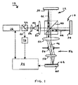
図1に、本発明にしたがって構成された画像ベース周波数偏移干渉計10が、個別の試験アーム12及び基準アーム14を有するマイケルソン干渉計の形態で示される。フィゾー干渉計のような、共通試験/基準アーム構成を有するその他の形態の干渉計も本発明の実施に用いることができる。そのような干渉計は様々な測定ビーム周波数において複数の干渉パターンをつくり、処理することができる能力を有することが好ましい。
In FIG. 1, an image-based
例えば、図示される干渉計10はある範囲の離散周波数にわたって調節可能な周波数を有する測定ビーム20を放射する周波数可変レーザ16を有する。半反射器の形態を有することが好ましいビームスプリッタ22が測定ビーム20の小率部分を周波数アナライザ24に分岐する。周波数アナライザ24によって測定ビーム周波数が測定され、周波数情報は、後に計算を行うために周波数情報を格納することができ、またはレーザ16を所望の周波数にさらに同調させるためのフィードバック信号を生成することができる、コンピュータ26にわたされる。
For example, the illustrated
周波数アナライザ24はそれ自体が、ビーム周波数の変化を測定するためのエタロンまたはキャビティとして構成された基準面を有する共通経路干渉計のような、干渉計の形態をとることができる。固定基準面間隔において、測定ビーム周波数の変化は、対応する、基準面に当る相異なる測定ビーム部分間の干渉における変化を生じさせる。干渉の変化は測定ビーム周波数の変化として解釈することができる。
The
エタロンまたはキャビティの比較または組合せに対して既知の周波数を有する個別の基準ビームは測定ビーム周波数の絶対値を決定するために用いることができる。周波数アナライザ24は、一般によりよく制御された環境にある、周波数可変レーザ16に近接して配置されることが好ましいが、測定ビーム20のサンプリングは、そのようなサンプリングが干渉計10によってなされる目的の測定に有害な影響を与えるであろう箇所は除き、ビームの長さに沿うどこででも行うことができる。
A separate reference beam having a known frequency for the etalon or cavity comparison or combination can be used to determine the absolute value of the measurement beam frequency. Although the
本発明の実施に好ましい周波数可変レーザは、本出願と同一日付で出願された、題名を「モード選択周波数同調システム(MODE-SELECTIVE FREQUENCY TUNING SYSTEM)」とする米国特許出願明細書に開示されている。本発明の実施に好ましい周波数アナライザは、同じく本出願と同一日付で出願された、題名を「モード選択同調器からの光フィードバック(OPTICAL FEEDBACK FROM MODE-SELECTIVE TUNER)」とする米国特許出願明細書に開示されている。 A preferred tunable laser for practicing the present invention is disclosed in a US patent application filed on the same date as the present application and entitled “MODE-SELECTIVE FREQUENCY TUNING SYSTEM”. . A preferred frequency analyzer for practicing the present invention is a U.S. patent application that is also filed on the same date as the present application and entitled “OPTICAL FEEDBACK FROM MODE-SELECTIVE TUNER”. It is disclosed.
ビーム拡大器28及びコリメータ30が垂直入射で試験面32及び基準面34のいずれをも照射するために測定ビーム20を整形する。かすり角を含むその他の入射角も、反射率を高めるかまたは表面変化をフィルタリングするような目的のために、用いることができよう。乱反射性の試験面32及び基準面34は、本明細書に参照として含まれる、題名を「非鏡面反射基準面をもつ周波数走査型干渉計(FREQUENCY-SCANNING INTERFEROMETER WITH NON-SPECULAR REFERENCE SURFACE)」とする同時係属米国特許出願公開第10/610235号明細書に開示されているように、コリメートされていない(例えば発散する)ビームで照射することができよう。
The beam expander 28 and
ビームスプリッタ40が測定ビーム20を、それぞれが試験面32及び基準面34から反射してビームスプリッタ40に戻る、試験ビーム成分42及び基準ビーム成分44に分ける。またビームスプリッタ40は反射された試験ビーム成分42及び基準ビーム成分44を再合体させて、試験面32と基準面34の間の差に関する情報でエンコードされた、変調測定ビーム46にする。偏波維持光に対しては、ビームスプリッタ40を通って進行する光の方向を管理するための試験アーム12及び基準アーム14に沿って1/4波長位相遅延板(図示せず)とともに用いられる偏光ビームスプリッタとしてビームスプリッタ40を構成することができる。
The
結像コンポーネント50及び52がアパーチャひとみ54とともに、視野全体にかけて局所強度を検知するためのピクセルアレイ62を組み込んでいる検出器60上に試験面32及び基準面34を結像するための、テレセントリック結像系56を形成する。図示されるテレセントリック結像系56のような、テレセントリック結像系は、結像される面の様相の遠近誤差を最小限に抑えるため、特に好ましいが、技術上既知の実践に相反しないその他の目的のためにその他の結像及び照明光学系を用いることができる。再合体した試験ビーム成分42と基準ビーム成分44の総強度の均衡をとって検出器60における干渉コントラストを最適化するために、ビームスプリッタ40または試験ビーム成分42及び基準ビーム成分44に別個に作用する別の光学系に対する調節手段を用いることができる。
Telecentric coupling for
コンピュータ26は、複数の様々な測定ビーム周波数のそれぞれにおいて検出器60上に結像される干渉パターンを記録するため、フレームグラッバーの組込みによるように、検出器60と関連して構成されることが好ましい。それぞれのピクセルからの強度データは、データがつくられた測定ビーム周波数に(例えばその順序により)関連付けられて、セットで構成されることが好ましい。それぞれのピクセルについてのデータセットは、検出器ピクセルアレイ62の個々のピクセル上に結像される試験面32及び基準面34のそれぞれの有限領域からの試験ビーム成分42と基準ビーム成分44の間の2πを法とする位相オフセットに関係付けられる干渉情報を含む。
The
強度データが関連付けられる測定ビーム周波数に関する情報は周波数アナライザ24、その他の測定源から、あるいはあらかじめ定められた目標値から、収集することができる。通常の周波数偏移干渉法では、測定ビームの実周波数の精確な知識なしにデータの周期縮重処理が可能になる、等間隔測定ビーム周波数の使用が好まれる。しかし、実測定ビーム周波数に関する情報により、不等間隔測定ビーム周波数を使用して、本発明にしたがってなされる測定の確度を高め、範囲を広げることができる。例えば、追加の測定ビーム周波数を必要とせずに、あるいは測定範囲を犠牲にせずに、確度を向上させるかまたはその他の許容度を緩めるために、より間隔の広い測定ビーム周波数をより間隔が密な測定ビーム周波数と組み合わせて用いることができる。
Information regarding the measurement beam frequency with which the intensity data is associated can be collected from the
検出器ピクセルアレイ62の一ピクセルについての強度信号I(ν)は基準ビーム成分U基準と試験ビーム成分U試験の干渉として、式(3):
と書くことができる。ここで信号I(ν)は測定ビーム周波数νの関数として記録される。 Can be written. Here, the signal I (ν) is recorded as a function of the measurement beam frequency ν.
基準ビーム成分U基準はさらに、式(4):
と書くことができる。ここでI基準は基準ビーム成分44の強度、cは光の速度、D基準はレーザ源16から基準面34までの光学距離、νはレーザ周波数である。
Can be written. Here, the I reference is the intensity of the reference beam component 44, c is the speed of light, the D reference is the optical distance from the laser source 16 to the
同様に、試験ビーム成分U試験は、式(5):
で与えられる。ここでI試験は試験ビーム成分42の強度、D試験はレーザ源16から試験面32までの光学距離である。
Given in. Here, the I test is the intensity of the
式(4)及び(5)を式(3)に代入すれば、式(6):
が得られる。ここで距離D=D基準−D試験である。試験ビーム成分42及び基準ビーム成分44はそれぞれ試験アーム12及び基準アーム14に沿って折り返されるから、距離Dは試験ビーム成分42と基準ビーム成分44の間の光路長差の1/2に等しい。
Is obtained. Here, distance D = D reference− D test . Since the
式(6)は、干渉計10のような、位相偏移干渉計を用いる測定に対する基礎をなす。基本課題はサンプリングされる測定ビーム周波数において一連の強度測定値を生じる距離Dの値を決定することである。
Equation (6) forms the basis for measurements using a phase shift interferometer, such as
式(6)の簡略化された離散表記において、偏りが引き去られ、絶対値が1に規格化された、期待される強度I'nは、式(7):
として与えられる。ここでI'nは第n測定ビーム周波数において記録される一ピクセルにおける期待強度値であり、νnは第n測定ビーム周波数値である。 As given. Here, I ′ n is an expected intensity value in one pixel recorded at the n-th measurement beam frequency, and ν n is an n-th measurement beam frequency value.
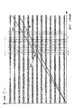
2つの相異なる距離D1及びD2の期待強度パターンの誇張された説明が図2のグラフに見られる。それぞれの対応する位相コンポーネントacross(I'n)の尺度としてある範囲の強度値I'nが測定ビーム周波数ドメインにわたってプロットされている。距離D1及びD2は、原点から延び、共通の測定周波数ドメインにわたる位相の変化率を表す勾配によって弁別される、直線として見える。 An exaggerated description of the expected intensity patterns for two different distances D1 and D2 can be seen in the graph of FIG. A range of intensity values I ′ n is plotted over the measurement beam frequency domain as a measure of each corresponding phase component across (I ′ n ). The distances D1 and D2 appear as straight lines that are distinguished from each other by a gradient that extends from the origin and represents the rate of change of phase over a common measurement frequency domain.
測定ビーム周波数が変化するにつれて、2つの距離D1及びD2の位相は複数の周期の増加的干渉と減殺的干渉にわたって偏移する。位相偏移レートは、それぞれの勾配が異なるために距離D1とD2の間で異なる。ビーム周波数ドメイン(すなわち横軸)に沿い、距離Dの2倍で光の速度を除した商(すなわちc/2D)に等しい周波数幅毎に、与えられた距離Dに対する完全な2π位相変化周期がともなう。位相ドメインに沿い、完全な一2π干渉周期は注目される測定ビーム周波数における測定ビーム波長の1/2に等しい距離Dの変化に相当する。すなわち、測定ビーム周波数のいずれの1つにおいても、完全な2π位相変化周期を生じるに必要な距離変化は、通常の位相偏移干渉法について期待されるように、測定ビーム波長の1/2に等しい。 As the measurement beam frequency changes, the phase of the two distances D1 and D2 shifts over multiple periods of incremental and destructive interference. The phase shift rate differs between the distances D1 and D2 due to the different slopes. For every frequency width along the beam frequency domain (ie the horizontal axis) equal to the quotient (ie c / 2D) divided by the speed of light by twice the distance D, a complete 2π phase change period for a given distance D is obtained. Along with. Along the phase domain, a complete 1 2π interference period corresponds to a change in distance D equal to 1/2 of the measurement beam wavelength at the measurement beam frequency of interest. That is, at any one of the measurement beam frequencies, the distance change required to produce a complete 2π phase change period is ½ of the measurement beam wavelength, as expected for normal phase shift interferometry. equal.
測定ビーム周波数が高まるにつれて、完全な2π位相変化周期に対応する勾配の変化は小さくなる。可視スペクトル内で測定値をとるためには300,000GHzをこえる測定ビーム周波数が考えられる。与えられた測定ビーム周波数において、2つの、差が非常に小さい、距離の間の位相差は同じ距離の間の勾配差よりかなり顕著である。したがって、公称測定ビーム周波数における注目される2つの距離の間の位相差に相当する位相オフセットは、2つの距離の勾配に相当する測定ビーム周波数の位相変化周波数よりかなり急速に変化する。しかし、限定された同義区間が位相オフセットにはあるが、実用目的に対し、勾配にはない。公称測定ビーム波長の1/2の増分で隔てられる距離は、位相オフセットが2π以外の大きさで変化する別の距離よりもかなりよく、与えられた距離Dの強度/位相パターンに一致する。 As the measurement beam frequency increases, the change in slope corresponding to the full 2π phase change period decreases. Measurement beam frequencies exceeding 300,000 GHz are conceivable for taking measurements in the visible spectrum. For a given measurement beam frequency, the phase difference between the two, very small differences, is much more pronounced than the gradient difference between the same distances. Thus, the phase offset corresponding to the phase difference between the two distances of interest at the nominal measurement beam frequency changes much more rapidly than the phase change frequency of the measurement beam frequency corresponding to the gradient of the two distances. However, although there is a limited synonym section in the phase offset, it is not in the gradient for practical purposes. The distance separated by an increment of 1/2 of the nominal measurement beam wavelength is much better than another distance where the phase offset varies by a magnitude other than 2π and matches the intensity / phase pattern of a given distance D.
すなわち、位相オフセット及び位相変化周波数はいずれも距離Dの尺度を与える。位相オフセットは実距離Dの近傍でより一層顕著であるが、公称測定ビーム波長の1/2に等しい、狭い同義区間を有する。しかし、位相オフセットは可能な距離Dの選択を、位相変化周波数(すなわち勾配)の比較をより効率的に行うことができる距離間隔に限定する。 That is, both phase offset and phase change frequency provide a measure of distance D. The phase offset is more pronounced near the actual distance D, but has a narrow synonym interval equal to 1/2 of the nominal measurement beam wavelength. However, the phase offset limits the selection of possible distances D to distance intervals that can more efficiently compare phase change frequencies (ie, gradients).
例えば、距離Dの測定はモデルデータと測定データの間で最善の一致を生じる値D'を決定することによって達成することができる。最小二乗法にしたがって、式(8):
のメリット関数を一致の評価に用いることができる。ここで、ε(D')は試行距離D'における誤差メリット値、Inは第n測定ビーム周波数において記録されたあるピクセルにおける規格化強度値(すなわち測定データ)であり、総和はN個の測定ビーム周波数にわたってとられる。In(nの範囲は1からN)についてのデータセットは、強度値を生じさせる測定ビーム周波数νnに関連付けられる単一ピクセルについての規格化強度値のセットに対応する。 The merit function can be used for matching evaluation. Here, epsilon (D ') is attempted distance D' error merit value in, I n is the normalized intensity values (i.e., measurement data) at a pixel recorded at the n measuring beam frequency, sum of N Taken over the measurement beam frequency. The data set for I n (where n ranges from 1 to N) corresponds to the set of normalized intensity values for a single pixel associated with the measurement beam frequency ν n that yields the intensity value.
最小二乗法により、誤差はD'に関するεの導関数がゼロに等しい点において最小になる。導関数は式(9):
で与えられる。 Given in.
式(9)の最終項はデータに依存しないからこれを無視することができ、よって式(10):
で与えられるメリット関数が得られる。 The merit function given by is obtained.
式(10)をさらに簡単にするため、光周波数(すなわち300,000GHz以上)の領域においては、νnの値が代表的な同調帯域幅にわたって極めて僅かにしか変化せず、したがって総和記号のすぐ右のνn項は無視できることに留意することができる。 To further simplify equation (10), in the region of the optical frequency (ie, 300,000 GHz or more), the value of ν n varies very little over a typical tuning bandwidth, so It can be noted that the right ν n term is negligible.
式(10)のε'を最小にするD'を見いだすことにより、位相オフセット及び位相変化周波数をともに測定ビーム周波数に整合させる、D'に対する解を得ることができる。この手法により、不等間隔周波数サンプリングを含む、測定ビーム周波数のサンプリングの変形も可能になる。νnの値が既知である限り、確度、再現性、時間及びコストを含む、特定の目標を達成するために望まれるように、νnの値を分布させることができる。 By finding D ′ that minimizes ε ′ in equation (10), a solution to D ′ can be obtained that matches both the phase offset and the phase change frequency to the measurement beam frequency. This technique also allows for variations in sampling of the measurement beam frequency, including non-uniform frequency sampling. As long as the value of ν n is known, the value of ν n can be distributed as desired to achieve a particular goal, including accuracy, reproducibility, time and cost.
式(10)は他のメリット関数が可能であることも示す。例えば、サイン変換を最小にするのではなく、フーリエ変換の実数部に等価な、式(11):
にしたがう、コサイン変換を最大化することもできよう。 So you could maximize the cosine transformation.
最小二乗法の実施は直截的である。式(7)におけるような、データ値ベクトル及び周波数値ベクトルが与えられれば、式(11)を最大にするD'の値を計算するための試験のために、あらかじめ計算された「正弦波マトリックス」を構成することができる。 The least squares method is straightforward. Given a data value vector and a frequency value vector, as in equation (7), a pre-computed “sinusoidal matrix” for testing to calculate the value of D ′ that maximizes equation (11). Can be configured.
式(11)のメリット関数から不要な偏りを除去するために規格化を用いることができる。規格化メリット関数は、強度値が式(11)のコサイン項に完全に対応するときに値1を有する。規格化メリット関数は、式(12):
で与えられる。 Given in.
このアルゴリズムの実施の重要な実用的態様は、式(12)のメリット関数が波長オーダーの精細な詳細を有することである。例えば、実距離D及び測定ビームの公称波長の1/2の間隔で隔てられた別の値D'に対応する位相オフセットは、容易に同定することができる、局所相関ピークを示す。 An important practical aspect of the implementation of this algorithm is that the merit function of equation (12) has fine details on the order of wavelengths. For example, a phase offset corresponding to another value D ′ separated by an actual distance D and a half of the nominal wavelength of the measurement beam indicates a local correlation peak that can be easily identified.
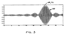
28μmのピクセル距離Dに対して表1に挙げられている入力値に基づく式(12)の実用的特徴は、異なるスケールで図3及び4に提示されている式(12)の2つのプロットから明らかである。図3にプロットされている、得られた、式(12)の規格化メリット関数は0〜40μmの範囲の距離D'の候補の間の相関の変化を示す。図4は26〜30μmの距離に対する同じメリット関数を示す。
図3のプロットの主ローブすなわち包絡線70の半値全幅(FWHM)の値は、式(2)で与えられる値の1/2に少なくともほぼ相当する、4.88μmである。式(2)の値は、距離D'が試験ビーム42と基準ビーム44の間の光路長差の1/2に等しいことから、1/2にされる。主ローブすなわち包絡線70内で、メリット関数は、ほぼ0.4μmの測定ビームの公称波長の1/2で隔てられた多くの(ほぼ12の)鋭い局所ピークを有する。最大局所ピーク72は28μmに等しい試験距離D'におけるメリット関数の主ローブ70の汎ピーク68に対応する。
The value of the full width at half maximum (FWHM) of the main lobe or
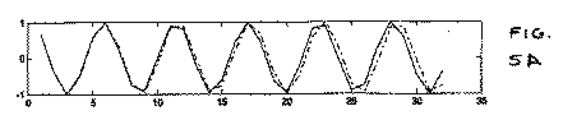
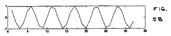
図5A〜5Dは、(実線で示される)28μmの実距離Dにおける規格化データのプロットを(一点鎖線で示される)D'の別の試験値のプロットと比較して示す。実値は、実値が収集される測定ビーム周波数に関連付けられた規格化強度の理想化されたピクセルデータセットに相当する。図5Bは28μmの実距離Dについて32の等間隔増分測定ビーム周波数において収集された規格化強度を連結しているプロットを示す。測定ビーム周波数にともなう位相変化周波数はプロットされた強度変化の正弦波形状から明らかである。 5A-5D show a plot of normalized data at an actual distance D of 28 [mu] m (indicated by a solid line) compared to another test value plot of D '(indicated by a dashed line). The actual value corresponds to an idealized pixel data set of normalized intensity associated with the measurement beam frequency from which the actual value is collected. FIG. 5B shows a plot linking the normalized intensities collected at 32 equally spaced incremental measurement beam frequencies for an actual distance D of 28 μm. The phase change frequency with the measurement beam frequency is apparent from the sinusoidal shape of the plotted intensity change.
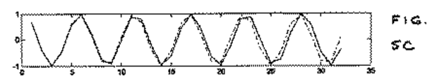
図5Aは28μmより短い(ほぼ27.6μm)初期波長の1/2の試験距離D'に対して期待される初期値を示し、図5Cは28μmより長い(ほぼ28.4μm)初期波長の1/2の試験距離D'に対して期待される初期値を示す。図5A及び5Cのプロットは初期測定ビーム周波数において実距離Dのプロットと一致し、ビーム周波数測定範囲全体にわたってごく僅かな大きさだけ位相が徐々に外れてゆく。したがって、図5A及び5Cの試験距離D'は最大局所ピーク72を夾叉する局所相関ピーク74及び76に少なくともほぼ対応している。同様の位相偏移周波数を有するが真の距離Dからは初期波長の1/4だけ外れている、より短い別の試験距離D'(例えば28.2μm)では、位相がπにわたって偏移し、相関の谷を生じる。 FIG. 5A shows the initial value expected for a test distance D ′ of ½ of the initial wavelength shorter than 28 μm (approximately 27.6 μm), and FIG. 5C shows 1 of the initial wavelength longer than 28 μm (approximately 28.4 μm). The initial value expected for the test distance D ′ of / 2 is shown. The plots of FIGS. 5A and 5C coincide with the plot of the actual distance D at the initial measurement beam frequency, and are gradually out of phase by a very small amount over the entire beam frequency measurement range. Accordingly, the test distance D ′ in FIGS. 5A and 5C corresponds at least approximately to the local correlation peaks 74 and 76 that fork the maximum local peak 72. At other shorter test distances D ′ (eg, 28.2 μm) that have similar phase shift frequencies but deviate from the true distance D by ¼ of the initial wavelength, the phase shifts over π, This produces a correlation valley.
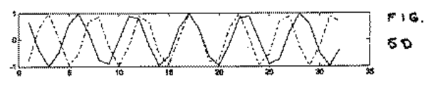
図5Dは、FWHMピーク幅が4.88μmだけ変化する試験距離D'のプロットに対して28μmの実距離Dのプロットを比較する。測定ビーム周波数のサンプリング範囲にわたり、2つのプロットの間に2π位相偏移が生じている。ビーム周波数範囲の中央近傍の一測定周波数において重なり合うプロットは良く一致している(最小の位相オフセットを表している)が、ビーム周波数範囲の両端においてプロットのずれは最も大きく、相関が大きく低下している。言い換えれば、2π位相オフセットに相当する距離においてさえも、位相変化周波数の誤差(すなわち勾配の誤差)がより有意になるため、距離に大きな誤差があると相関がかなり低下する。 FIG. 5D compares the plot of the actual distance D of 28 μm against the plot of the test distance D ′ where the FWHM peak width varies by 4.88 μm. There is a 2π phase shift between the two plots over the sampling range of the measurement beam frequency. The overlapping plots at one measurement frequency near the center of the beam frequency range are in good agreement (representing the smallest phase offset), but the plot shift is greatest at both ends of the beam frequency range, and the correlation is greatly reduced. Yes. In other words, even at a distance corresponding to a 2π phase offset, the phase change frequency error (ie, the gradient error) becomes more significant, and a large error in the distance significantly reduces the correlation.
式(12)の相関メリット関数を用いれば、隣接ピクセルの距離にかかわらずピクセル毎のベースで距離Dを決定することができる。D'の値は個々のピクセルから収集される規格化データにより局所相関ピークが見いだされるまで対称的に変化する。局所相関ピークが見いだされると、より高い相関を達成するための残りのD'の選択数は公称測定ビーム波長の1/2の整数倍にほとんど制限される。したがって、収束の速さ及び確度のいずれにも寄与する、相関の位相オフセット要件によって、(位相変化周波数、すなわち測定される距離Dの勾配も一致する)汎ピーク68への収束が示される。 If the correlation merit function of Expression (12) is used, the distance D can be determined on a pixel-by-pixel basis regardless of the distance between adjacent pixels. The value of D ′ varies symmetrically until a local correlation peak is found by the normalized data collected from the individual pixels. Once a local correlation peak is found, the number of remaining D 'choices to achieve higher correlation is almost limited to an integer multiple of 1/2 the nominal measurement beam wavelength. Thus, the phase offset requirement of the correlation, which contributes to both the speed and accuracy of convergence, indicates convergence to the pan peak 68 (which also matches the phase change frequency, ie the slope of the measured distance D).
ある意味で、局所ピークの同定は位相偏移の同定と等価である。対応する位相にピクセル強度値を総体的に関連付けるために狭い距離範囲にわたり固定測定ビーム周波数においてデータを収集する代りに、好ましい本発明は、対応する位相にピクセル強度値を総体的に関連付けるために狭い測定周波数ビーム範囲にわたり固定距離においてデータを収集する。しかし、従来の位相偏移とは異なり、位相オフセットを同定するために用いられるものと同じ相関関数を、ピクセルが基準面に対して配置される距離Dを決定するために同じ位相オフセットを示す距離D'の中から選択するために用いることができる。 In a sense, identifying a local peak is equivalent to identifying a phase shift. Instead of collecting data at a fixed measurement beam frequency over a narrow range of distances to generally associate pixel intensity values with corresponding phases, the preferred invention is narrow to associate pixel intensity values with corresponding phases in a general manner. Collect data at a fixed distance over the measurement frequency beam range. However, unlike conventional phase shifts, the same correlation function that is used to identify the phase offset is a distance that indicates the same phase offset to determine the distance D at which the pixel is located relative to the reference plane. Can be used to select from D ′.
相関探査の出発点として試験面の形状及び位置の背景知識を用いることができ、あるいは通常の周波数偏移干渉法に対して用いられる手順と同様の推定値を導くためにピクセルデータセットを前処理することができる。例えば、離散測定ビーム周波数において収集された強度データを試験するための最初の工程として、通常のフーリエ変換または高速フーリエ変換を用いることができる。周波数偏移干渉法に対するフーリエ変換の使用に関する詳細は、本明細書に参照として含まれる、題名を「周波数走査型干渉計のための多段階データ処理(MULTI-STAGE DATA PROCESSING FOR FREQUENCY-SCANNING INTERFEROMETER)」とする、米国特許第6741361号明細書に開示されている。 Background knowledge of test surface shape and position can be used as a starting point for correlation exploration, or pixel data sets are preprocessed to derive estimates similar to those used for normal frequency-shifting interferometry can do. For example, a normal Fourier transform or a fast Fourier transform can be used as an initial step for testing intensity data collected at discrete measurement beam frequencies. For more information on the use of Fourier transforms for frequency-shifting interferometry, the title “MULTI-STAGE DATA PROCESSING FOR FREQUENCY-SCANNING INTERFEROMETER” is included herein by reference. In U.S. Pat. No. 6,741,361.
フーリエ変換の(測定ビーム周波数に対する位相変化の勾配に相当する)サンプル周波数は離散しているため、強度データ点の(ビンと称される)サンプルフーリエ周波数とのフィッティングは完全ではなく、フィッティングのずれの程度は変化する傾向がある。ピーク周波数近傍における振幅に対して放物線形を仮定することによってサンプリングされたフーリエ周波数の最大振幅の間を補間するために通常のルーチンを用いることができる。ピークフーリエ周波数を見いだすためにより広いサンプルフーリエ周波数範囲にわたって得られるサンプルフーリエ周波数振幅に重み付けする、「モーメントアーム」法がこの目的のために好ましい。他の方法では連続して繰り返され得ない、限定された範囲にわたってデータが存在する場合には通常のウインドウ処理法を用いることができる。 Since the sample frequency of the Fourier transform (corresponding to the gradient of the phase change with respect to the measurement beam frequency) is discrete, the fitting of the intensity data points with the sample Fourier frequency (called bin) is not perfect and the fitting shift The degree of changes tends to change. A normal routine can be used to interpolate between the maximum amplitudes of the sampled Fourier frequencies by assuming a parabolic shape for the amplitudes near the peak frequency. The “moment arm” method, which weights the sample Fourier frequency amplitude obtained over a wider sample Fourier frequency range to find the peak Fourier frequency, is preferred for this purpose. If the data exists over a limited range that cannot be repeated continuously by other methods, a normal windowing method can be used.
同定されたフーリエ周波数は、式(12)のメリット関数において具現化される反復カーブフィッティング手順のための出発点として、試験距離D'に変換することができる。試験距離D'は、メリット関数を用いるための時間節約出発点を与えるために、メリット関数の主ローブすなわち包絡線70内に入ることが好ましい。いくつかの例においては、このレベルの確度を達成するにはフーリエ周波数間の弁別だけで十分であり得るが、別の例においてはさらに精細な補間手順が必要であり得る。フーリエ変換から見いだすこともできる強度オフセットを強度データを規格化するために用いることができる。周波数アナライザ24は、様々な測定ビーム周波数の間の強度変化を測定することもできる。
The identified Fourier frequency can be converted to a test distance D ′ as a starting point for the iterative curve fitting procedure embodied in the merit function of equation (12). The test distance D ′ preferably falls within the main lobe or
式(12)のメリット関数を適用するための反復手順は2段階で行うこともできる。反復の第1段階では、主ローブすなわち包絡線70内の局所相関ピークの1つの形態で局所最大が見いだされる。データを放物線で近似する、ブレント法のような、非線形フィッティングアルゴリズムを局所最大の1つへの収束を速めるために用いることができる。反復の第2段階では、同じ位相オフセットを共有する局所相関ピークの中からの選択に限定することができる大域最大が見いだされる。同様の非線形フィッティングアルゴリズムを公称測定ビーム波長の1/2の整数倍において相関関数を評価する大域最大への収束を速めるために用いることができる。最大局所ピーク72の主ローブすなわち包絡線70の汎ピーク68との接点におけるメリット関数の最終収束により、周波数エイリアシングを受ける通常の周波数偏移干渉法の範囲をもこえる、基準面34からの個々のピクセルの絶対距離に相当する測定範囲にわたって通常の位相偏移干渉法にともなう確度に等価な(または少なくとも近づく)確度でのピクセル距離Dの測定が可能になる。
The iterative procedure for applying the merit function of equation (12) can also be performed in two stages. In the first stage of the iteration, a local maximum is found in one form of a local correlation peak in the main lobe or
式(12)のメリット関数は距離D'に相当する正弦波周波数の中からより良く弁別するために位相尺度を用いることによって個々のピクセルの位相尺度を自動的に解開する(すなわち、2πを法として位相の同義性を解く)。しかし、正弦波の位相及び周波数の情報は別々の段階で収集するかまたは結合させることができる。例えば、強度データセットに適用されるフーリエ変換は、サンプリングされた正弦波周波数の振幅寄与だけでなく、それらの位相オフセットも返す。距離Dの近傍の試験距離D'に対応するサンプリングされた周波数は同じ位相オフセットに関係付けられると考えることができる。最大振幅周波数サンプル間の補間によりピーク正弦波周波数に対応する距離Dの個別の尺度をつくることができる。 The merit function of equation (12) automatically solves the individual pixel phase measure by using the phase measure to better discriminate among the sinusoidal frequencies corresponding to the distance D ′ (ie, 2π). As a law, the synonym of phase is solved). However, sinusoidal phase and frequency information can be collected or combined in separate stages. For example, a Fourier transform applied to an intensity data set returns not only the amplitude contribution of sampled sinusoidal frequencies, but also their phase offset. It can be considered that the sampled frequencies corresponding to the test distance D ′ in the vicinity of the distance D are related to the same phase offset. An individual measure of the distance D corresponding to the peak sine wave frequency can be created by interpolation between the maximum amplitude frequency samples.
自動位相解開は、公称ビーム周波数における位相オフセットを用いて距離D'の中からの選択を公称測定ビーム波長の1/2の整数倍にある距離D'に制限することによって達成することができる。最大振幅周波数に最も近い距離D'が距離Dの尺度と見なされる。あるいは、それぞれのピクセルについて相対位相オフセットを決定し、隣接ピクセル間の2π位相区間の数を解くためにピーク正弦波周波数からの距離Dの尺度を用いることにより、通常の位相解開を用いてそれぞれのピクセルの相対高さを見いだすことができる。実際、式(12)のメリット関数はそのように用いることもできる。それぞれのピクセルには最も高いサブピークによって決定されるように位相オフセットが割り当てられる。距離Dは最高サブピークの間の補間によって見いだされるが、最終尺度とは見なされない。代りに、ピクセル間の残余2π位相多義性を解くために、距離Dのピクセル間変化が用いられる。 Automatic phase cleaving can be achieved by using a phase offset at the nominal beam frequency to limit the selection from within distance D 'to a distance D' that is an integral multiple of 1/2 the nominal measurement beam wavelength. . The distance D ′ closest to the maximum amplitude frequency is taken as a measure of the distance D. Alternatively, using normal phase cleaving by determining the relative phase offset for each pixel and using a measure of distance D from the peak sine wave frequency to solve for the number of 2π phase intervals between adjacent pixels, respectively. You can find the relative height of the pixels. In fact, the merit function of equation (12) can also be used as such. Each pixel is assigned a phase offset as determined by the highest subpeak. The distance D is found by interpolation between the highest subpeaks but is not considered a final measure. Instead, the inter-pixel change in distance D is used to solve the residual 2π phase ambiguity between pixels.
多くの変数が、測定ビーム周波数及びその変化が既知である確度を含む、測定の確度に影響を与え得る。測定ビーム周波数の精確な知識は、距離Dの絶対測定を含む、より広い範囲の測定をサポートする。 Many variables can affect the accuracy of the measurement, including the accuracy with which the measurement beam frequency and its changes are known. Accurate knowledge of the measurement beam frequency supports a wider range of measurements, including absolute measurements of distance D.
式(12)のメリット関数の主ローブすなわち包絡線は、最長距離が最短距離よりも1つ多い位相変化の完全な一周期をとる試験距離D'の範囲にわたる。局所相関ピーク(例えば72,74及び76)は主ローブすなわち包絡線70を公称測定ビーム波長の1/2で隔てられる増分距離に分割する。主ローブすなわち包絡線70内の局所ピークを弁別するため、測定ビーム周波数範囲にわたる位相偏移Δφは、式(13):
として、局所ピークを分離する位相変化の完全な一周期の分域内にあると知られていることが好ましい。ここでλoは測定ビームの公称波長である。 As described above, it is preferable to be known to be in the domain of one complete cycle of phase change separating the local peaks. Where λ o is the nominal wavelength of the measurement beam.
位相偏移Δφに等価な式を、公称測定ビーム周波数νoにわたる総ビーム周波数変化範囲Δν総または公称波長λoにわたる総ビーム波長変化範囲Δλ総に関して、式(14):
と書くことができる。 Can be written.
これらの式から、測定ビーム周波数帯域幅を広げると主相関ローブ70内の局所即間ピークの数が減少することによって位相偏移弁別に対する許容度が広がると推測することができる。局所相関ピーク(例えば72,74及び76)は公称測定ビーム波長の1/2で隔てられたままであるが、帯域幅が広がるにつれて主相関ローブ70が狭くなる。
From these equations, it can be inferred that increasing the measurement beam frequency bandwidth increases the tolerance for phase shift discrimination by reducing the number of local immediate peaks in the
位相偏移Δφは、式(15):
として、測定ビーム周波数の不確定性に関係付けられる。ここでΔν不確定は測定ビーム周波数に対する不確定性または許容範囲である。 As related to the uncertainty of the measurement beam frequency. Here, Δν uncertainty is uncertainty or tolerance for the measurement beam frequency.
式(14)と式(15)を合せれば、測定ビーム不確定性の好ましい限界を、不等式(16):
または不等式(17):
と書くことができる。 Can be written.
表1に示される例でいえば、測定ビーム周波数不確定性Δν不確定はほぼ430GHzより小さくなければならない。局所相関ピーク間での弁別時に許容され得る測定ビーム周波数不確定性Δν不確定は距離Dが大きくなるにつれて小さくなる。したがって、測定ビーム周波数不確定性Δν不確定に対する許容度は、測定値をとるにあたって予測される最大距離Dにおいて設定されることが好ましい。 In the example shown in Table 1, the measurement beam frequency uncertainty Δν uncertainty should be approximately less than 430 GHz. The measurement beam frequency uncertainty Δν uncertainty that can be tolerated when discriminating between local correlation peaks decreases as the distance D increases. Therefore, the tolerance for the measurement beam frequency uncertainty Δν uncertainty is preferably set at the maximum distance D predicted for taking the measurement value.
公称ビーム周波数νoの仮定または決定における誤差は、主相関ローブ70内の局所ピークの位置に影響し得る。最大局所ピークは局所ピーク間隔の1/2まで主ローブ70の汎ピーク68からオフセットされ得る。ビーム周波数ドメイン(すなわち図2のグラフの横軸)に沿う、c/2Dに等しい周波数幅毎に、与えられた距離Dに対する位相変化の完全な2π周期がともなう。局所ピークオフセットは、公称測定ビーム周波数誤差によってとられるc/2Dの周波数幅の分域部分に関係付けられる。
Errors in the assumption or determination of the nominal beam frequency ν o can affect the position of the local peak in the
表1の例において、距離Dは28μmであり、よって干渉の完全な一周期をカバーする測定周波数ビーム幅はほぼ5360GHzに等しい。局所ピークの最大オフセットは、最大局所ピークが注目する公称測定ビーム波長の1/4に等しい距離で相関関数の汎ピーク68を夾叉する、ほぼ2680GHzの公称測定ビーム周波数誤差によって生じるであろう。28μmの距離Dに対して、5360GHzの整数倍の間隔で公称測定ビーム周波数誤差において同定される最大局所ピークは、相関関数の汎ピーク68と合ったままである。しかし、別のピクセルがあり得る別の距離Dにおいては、公称測定ビーム周波数誤差が正確な整数倍になってはいないであろう別の周波数間隔になると推定される。 In the example of Table 1, the distance D is 28 μm, so the measured frequency beam width covering one complete period of interference is approximately equal to 5360 GHz. The maximum offset of the local peak will be caused by a nominal measurement beam frequency error of approximately 2680 GHz that spans the correlation function pan peak 68 at a distance equal to 1/4 of the nominal measurement beam wavelength of interest. For a distance D of 28 μm, the maximum local peak identified in the nominal measurement beam frequency error at an integer multiple interval of 5360 GHz remains aligned with the pan peak 68 of the correlation function. However, at other distances D where other pixels may be, it is estimated that the nominal measurement beam frequency error will be at another frequency interval that may not be an exact integer multiple.
所望の確度を維持するため、多くの様々な手法を用いることができる。最も直接的な手法は、測定範囲全体にわたって所望の確度で相関関数の汎ピーク68に最大局所ピークが一致するように、十分な確度で公称測定ビーム波長を決定することである。この目的のために測定ビームの周波数を測定することができ、あるいは測定ビーム周波数の増分変化が既知であると仮定して、公称ビーム周波数に対する様々な値をメリット関数で試験して、様々な距離Dにおいて複数のピクセルについて最大局所相関ピークが見いだされる公称ビーム周波数を同定することができる。様々な距離Dのピクセル間の相関は公称測定ビーム周波数誤差を決定するために評価することもできる。あるいは、主相関ローブ70の汎ピーク68を近似するために最大局所ピークにカーブフィッティングまたはその他の補間法を適用することができる。
Many different techniques can be used to maintain the desired accuracy. The most direct approach is to determine the nominal measurement beam wavelength with sufficient accuracy such that the maximum local peak matches the pan peak 68 of the correlation function with the desired accuracy over the entire measurement range. For this purpose, the frequency of the measurement beam can be measured, or assuming that the incremental change of the measurement beam frequency is known, various values for the nominal beam frequency can be tested with the merit function to obtain different distances. The nominal beam frequency at which the maximum local correlation peak is found for multiple pixels at D can be identified. The correlation between pixels of various distances D can also be evaluated to determine the nominal measurement beam frequency error. Alternatively, curve fitting or other interpolation methods can be applied to the largest local peak to approximate the pan peak 68 of the
通常、それぞれのピクセルの基準面34上の対応点からの絶対距離Dよりピクセル間の高さの差を知ることが一層重要である。絶対距離Dの測定における系統誤差は無視できるか、そうではなくともピクセル間誤差変化が小さければ調整することができる。公称ビーム周波数の誤差によって生じる距離誤差は、一般に注目する公称ビーム波長の±1/4より小さい値に限定され、ピクセル間の高さ変化の関数としてこの限定範囲内の相互の値から測定値の総体距離まで変化する。1/4波長にほぼ等しい間隔で汎ピーク68を夾叉する局所ピーク間の選択により多義性問題が生じ得る。相関関数の最大局所ピークの同定におけるいかなる多義性も回避するため、公称ビーム周波数誤差はc/2Dの周波数スパンの1/3に制限されることが好ましい。
Usually it is more important to know the height difference between pixels than the absolute distance D from the corresponding point on the
式(12)のメリット関数のような、規格化相関からの距離の決定は、試験距離D'の選択に対するサンプリング手順に強く依存する。例えば、等間隔試験距離D'の格子上のサンプリングによる局所相関ピークの見いだしは、エイリアシングのために問題が生じ得る。以下の手順でこの困難が軽減される:
ステップ1.規格化相関関数の主ローブ70の位置を探し出す;
ステップ2.最大化ルーチンを用いて主ローブ70内の局所相間ピーク(例えば72,74または76)の位置を見いだす;
ステップ3.ステップ2で見いだされた局所ピークから1/2波長間隔だけ隔てられた別の局所相関ピークにおいて規格化相関をサンプリングする;
ステップ4.最大局所ピーク自体または局所ピークの組合せから主ローブ70の汎ピーク68の位置を見いだす。例えば、汎ピーク68の見いだしには局所ピークへのカーブフィッティングが役立ち得る。
The determination of the distance from the normalized correlation, such as the merit function of equation (12), depends strongly on the sampling procedure for the selection of the test distance D ′. For example, finding a local correlation peak by sampling on a grid of equidistant test distances D ′ can cause problems due to aliasing. The following steps will alleviate this difficulty:
Step 1. Find the position of the
Step 2. Find the location of the local interphase peak (eg 72, 74 or 76) in the
Step 3. Sampling the normalized correlation at another local correlation peak separated by a half wavelength interval from the local peak found in step 2;
Step 4. The position of the pan peak 68 of the
その中で距離Dを一意的に解くことができる距離変化範囲を限定する同義区間は、ピクセル強度パターン(すなわちピクセルデータセット)が1つの正弦波周波数より多くと一致するエイリアシングの問題から生じる。等増分の測定ビーム周波数でとられる測定値に対し、同義区間は式(1)で与えられる。同義区間をこえる実距離Dにともなうピクセル強度パターンは、1つより多くの試験距離D'にともなう推定強度パターンと一致し得る。より短い距離D,すなわち同義区間内の距離、あるいは特定の同義区間内にあることが知られている、より長い距離においては、強度パターンは1つの試験距離D'において一意的に一致し得る。しかし、特定の同義区間内にあることが知られていない、より長い距離Dにおいては、強度パターンは1つより多い試験距離D'において一致することができ、距離Dの真の尺度に不確定性が導入される。 A synonym section that limits the range of distance variation in which the distance D can be uniquely solved arises from aliasing problems where the pixel intensity pattern (ie, pixel data set) matches more than one sinusoidal frequency. For measurements taken at equal increments of measurement beam frequency, a synonym interval is given by equation (1). A pixel intensity pattern with an actual distance D that exceeds the synonym interval may match an estimated intensity pattern with more than one test distance D ′. At shorter distances D, i.e. distances within a synonym interval, or longer distances known to be within a specific synonym interval, the intensity patterns can uniquely match at one test distance D '. However, at longer distances D, which are not known to be within a specific synonym interval, the intensity pattern can match at more than one test distance D ′, and is uncertain on the true measure of distance D Sex is introduced.
式(1)から明らかなように、ビーム周波数増分の大きさを縮小することによって目的の測定範囲を包含するように同義区間を拡張することができる。しかし、式(2)から明らかなように、測定値の確度は、ビーム周波数増分の数Nを対応して増加させない限り、ビーム周波数増分を小さくするにつれて低下する。付随して処理時間が長くなるため、ビーム周波数増分の数Nを増加させることは歓迎されない。本発明にしたがえば、ピクセル強度パターンは、所望の測定値確度を達成すると同時に同義区間を拡張するために不等ビーム周波数間隔でつくることができる。結局のところ、そのような不等ビーム周波数変化はチャーピングと見なされる。 As is clear from equation (1), the synonym interval can be extended to encompass the target measurement range by reducing the magnitude of the beam frequency increment. However, as is apparent from equation (2), the accuracy of the measured value decreases as the beam frequency increment is decreased unless the number N of beam frequency increments is correspondingly increased. Increasing the number N of beam frequency increments is not welcome due to the associated increased processing time. In accordance with the present invention, pixel intensity patterns can be created with unequal beam frequency intervals to achieve the desired measurement accuracy and at the same time extend the synonym interval. After all, such unequal beam frequency changes are considered chirping.
例えば、意図されたビーム周波数変化範囲にわたり、その範囲の両端に限られるグループ内ではビーム周波数間隔を精細にすることができ、残りのグループの間隔はかなり広くすることができる。好ましい手法の1つでは、ビーム周波数範囲の第1の部分にわたって等しい大きさで隔てられ、ビーム周波数範囲の第2の部分では全く存在せず、第3の測定ビーム周波数範囲にわたって別の等しい大きさで隔てられた、一連のビーム周波数がつくられる。ビーム周波数範囲の両端に集合させられる周波数は、全ビーム範囲にわたって単一のレーザを同調させることでつくることができ、あるいはビーム周波数範囲の第1の部分と第3の部分のそれぞれの内で同調させるために別々のレーザを用いることができる。 For example, the beam frequency spacing can be fine within a group limited to both ends of the intended beam frequency variation range, and the spacing between the remaining groups can be quite wide. One preferred approach is equally spaced across the first portion of the beam frequency range, not present at all in the second portion of the beam frequency range, and another equal size across the third measurement beam frequency range. A series of beam frequencies separated by are produced. The frequencies collected at both ends of the beam frequency range can be created by tuning a single laser over the entire beam range, or tuned within each of the first and third portions of the beam frequency range. A separate laser can be used to achieve this.
ビーム周波数範囲の第1の部分及び第3の部分内で収集されたピクセル強度データに分離フーリエ変換を適用して、様々な公称ビーム周波数における位相オフセット及び正弦波周波数の2つの尺度を得ることができる。ピクセル強度データに多サンプル位相偏移アルゴリズムを適用することによって同様の位相オフセット尺度を得ることができる。12サンプルアルゴリズムが好ましい。第1の部分と第3の部分の間の公称ビーム周波数の変化の結果としての公称ビーム周波数範囲の第1の部分と第3の部分の間の位相オフセットの変化は、拡張された同義区間にわたる距離Dの正確な尺度を与えることができる。確度はビーム周波数範囲の第1の部分と第3の部分の間の総体間隔によって改善され、同義区間は同義区間の第1の部分内及び第3の部分内のより制限されたビーム周波数間隔によって拡張される。 Applying a separate Fourier transform to the pixel intensity data collected in the first and third portions of the beam frequency range to obtain two measures of phase offset and sinusoidal frequency at various nominal beam frequencies it can. A similar phase offset measure can be obtained by applying a multi-sample phase shift algorithm to the pixel intensity data. A 12 sample algorithm is preferred. The change in phase offset between the first and third portions of the nominal beam frequency range as a result of the change in nominal beam frequency between the first and third portions spans an extended synonym interval. An accurate measure of the distance D can be given. Accuracy is improved by the overall spacing between the first and third portions of the beam frequency range, and the synonym interval is due to the more limited beam frequency spacing within the first and third portions of the synonym interval. Expanded.
一般に、同義区間はピクセル強度データセットをフィッティングすることができる周波数の異なる正弦波の数を少なくすることによって拡張される。ビーム周波数間隔をより精細にすることは、与えられた測定範囲内の正弦波の数を少なくするための一手段である。別の手段は測定ビーム周波数間隔を不等にすることである。第1の部分内及び第3の部分内の間隔が相互に異なっていれば、より広いビーム周波数間隔をビーム周波数範囲の第1の部分及び第3の部分に適合させることができる。1つのビーム周波数間隔において与えられた距離Dについてつくられる強度パターンを一致させることができる正弦波周波数は、異なるビーム周波数間隔において同じ距離Dについてつくられる強度パターンを一致させることができる正弦波周波数と異なる。しかし、間隔の異なる強度パターンの内の一方または他方を一致させる正弦波周波数の中では、距離Dに対応する正弦周波数がいずれの強度パターンも一致させる。 In general, the synonym interval is extended by reducing the number of sinusoids of different frequencies that can fit the pixel intensity data set. Making the beam frequency spacing finer is one way to reduce the number of sinusoids within a given measurement range. Another means is to make the measurement beam frequency spacing unequal. If the spacing in the first part and the third part are different from each other, a wider beam frequency spacing can be adapted to the first part and the third part of the beam frequency range. A sinusoidal frequency that can match the intensity pattern created for a given distance D in one beam frequency interval is a sinusoidal frequency that can match an intensity pattern created for the same distance D in different beam frequency intervals. Different. However, among the sine wave frequencies that match one or the other of the intensity patterns with different intervals, the sine frequency corresponding to the distance D matches any intensity pattern.
ビーム周波数間隔は幾何的に、例えば対数的に変えることができ、あるいは、ビーム周波数範囲にわたって広くなるかまたは狭くなる間隔を生じる変化を含む様々な別の態様で変えることができる。ピクセル強度パターンへの正弦波一致から位相及び周波数の情報を解くために一般化フーリエ変換を用いることができる。(仮定されるいずれの間隔でもなく)強度Inが収集されるビーム周波数νnが式への入力であるから、式(10)または式(11)のサイン変換またはコサイン変換を用いて、規則的であるかまたは不規則なビーム周波数間隔に基づく相関関数内の正弦波位相及び周波数情報を解くことができる。 The beam frequency spacing can be varied geometrically, eg, logarithmically, or can be varied in a variety of other ways, including changes that produce spacing that widens or narrows across the beam frequency range. A generalized Fourier transform can be used to solve the phase and frequency information from the sinusoidal match to the pixel intensity pattern. Since the beam frequency [nu n intensity I n (nor any interval that is assumed) is collected is input to the expression, using sine transform or cosine transform of equation (10) or (11), rules The sinusoidal phase and frequency information in the correlation function based on ideal or irregular beam frequency spacing can be solved.
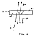
干渉計によってつくられる干渉パターンが試験面と基準面の間の多重干渉によって影響を受ける干渉計がある。例えば、フィゾー干渉計のような共通経路干渉計においては、図6に示されるように試験面80及び基準面82が光共振器90を形成し得る。入射ビーム84が透過成分86及び反射成分88に分けられ、それぞれが多重反射を受ける。したがって、干渉パターンの形成に寄与する光は多重反射を含む。この結果、干渉縞/スペックルパターンには、単反射干渉計で得られるコサイン形状からの偏りが生じ得る。
There are interferometers in which the interference pattern created by the interferometer is affected by multiple interference between the test surface and the reference surface. For example, in a common path interferometer such as a Fizeau interferometer, the
一例として、いずれの面の反射係数もRで与えられるフィゾー干渉計を考えることができる。この場合、干渉縞は式(18):
で与えられる形状を有する。ここでFは、式(19):
で与えられる。 Given in.
そのような干渉縞に対し、距離Dを測定する手順は、上記のステップ1として出発距離D'を同定し、次いで、式(18)とピクセルデータセットの間の規格化相関を最大にするD'の値が、式(12)で示されるようなピクセルデータセットとの規格化相関を最大にする式(7)の正弦波を見いだすことによってDを決定する代りに、下式:
で与えられる、より一般化された形の規格化相関関数にしたがって決定される。 Determined in accordance with a more generalized normalized correlation function given by
位相オフセットを最適化する最大局所ピーク72の、理想的には1の規格化相関に対応する、相関ローブ70の汎ピーク68との接点において、局所相関ピークを隔てる1/2波長距離の精細分割まで距離Dを絶対測定することができる。確度は主として、位相偏移干渉計と共通のシステム雑音及びその他の影響によって、また測定ビーム周波数の不確定性によっても、制限される。
Fine division of the ½ wavelength distance separating the local correlation peak at the point of contact with the pan peak 68 of the
局所相関ピークは、距離Dの値を決定するための汎ピークすなわち局所ピークの中の最大ピークの同定を示すために用いられることが好ましいが、局所ピークの内の1つであって好ましい最大ピークの同定は、ピクセル間の相対高さの比較を行うため及び通常の位相偏移干渉法にともなう目的を含むその他の目的のために公称ビーム周波数の位相オフセットを同定するために用いることができる。 The local correlation peak is preferably used to indicate the identification of the largest peak in the pan peak, ie the local peak, for determining the value of the distance D, but it is one of the local peaks and is the preferred maximum peak Can be used to perform relative height comparisons between pixels and to identify phase offsets of the nominal beam frequency for other purposes, including those associated with normal phase shift interferometry.
本発明は第一義的に表面の測定に向けられるが、測定ビーム間の時間オフセット測定に関する用途を含む、その他の干渉法用途に適用することもできる。例えば、物理的距離及び屈折率の測定を行うことができる。単レーザ源の同調、複レーザ源またはこれら2つの組合せにより、複数の測定ビーム周波数をつくることができる。測定ビーム周波数の数及び間隔は測定の総体距離及び距離測定範囲を含む様々な用途の要件に合せて調節することができる。 Although the present invention is primarily directed to surface measurements, it can also be applied to other interferometry applications, including those related to measuring time offsets between measurement beams. For example, physical distance and refractive index can be measured. Multiple measurement beam frequencies can be created by tuning a single laser source, multiple laser sources, or a combination of the two. The number and spacing of the measurement beam frequencies can be adjusted to meet various application requirements, including the total distance of the measurement and the distance measurement range.
本発明の好ましい実施形態を参照して本発明を特に示し、説明したが、当業者には、添付される特許請求の範囲に包含される本発明の範囲を逸脱することなく本発明の形態及び詳細に様々な変更がなされ得ることは当然であろう。 While the invention has been particularly shown and described with reference to preferred embodiments of the invention, those skilled in the art will recognize that the invention and forms thereof without departing from the scope of the invention as encompassed by the appended claims. Of course, various changes may be made in detail.
10 周波数偏移干渉計
12 試験アーム
14 基準アーム
16 周波数可変レーザ
20 測定ビーム
22,40 ビームスプリッタ
24 周波数アナライザ
26 コンピュータ
28 ビーム拡大器
30 コリメータ
32 試験面
34 基準面
42 試験ビーム成分
44 基準ビーム成分
46 変調測定ビーム
50,52 結像コンポーネント
54 アパーチャひとみ
56 テレセントリック結像系
60 検出器
62 ピクセルアレイ
DESCRIPTION OF
Claims (7)
様々な測定ビーム周波数において、基準面に対して前記試験面を比較する測定ビームの干渉部分間の複数の干渉パターンを形成する工程、
前記複数の干渉パターンから、干渉パターンが形成されたときのビーム周波数とペアにされ、かつ測定ビームの干渉部分間の位相オフセットに対応する強度関連値を、前記試験面上の個々の点に対応するセットにアレンジする工程、
前記試験面上の個々の点に関連付けられた前記強度関連値の各セットを、前記試験面までの距離の関数として位相オフセットと位相変化の周波数との双方が変化する周期関数と比較する工程、
前記強度関連値の各セットが、各強度関連値が対応する位相オフセットを集合的に参照するための前記周期関数により予測される位相オフセットにマッチする前記試験面までの複数の距離を識別する工程、及び、
前記強度関連値の各セットが前記周期関数により予測された位相オフセットにマッチする複数の距離の中から、前記強度関連値の各セットが前記周期関数により予測された前記位相変化の周波数に最もマッチする距離を識別し、前記試験面上の前記個々の点の間の前記高さ変化の尺度を提供する工程、
を含むことを特徴とする方法。 In the method of measuring the height change of the test surface,
Forming a plurality of interference patterns between interference portions of the measurement beam comparing the test surface against a reference surface at various measurement beam frequencies;
From the plurality of interference patterns, intensity-related values that are paired with the beam frequency when the interference pattern is formed and correspond to the phase offset between the interference portions of the measurement beam correspond to individual points on the test surface. The process of arranging the set to
Comparing each set of intensity-related values associated with individual points on the test surface to a periodic function in which both the phase offset and the frequency of phase change vary as a function of the distance to the test surface ;
Identifying a plurality of distances to the test surface where each set of intensity related values matches a phase offset predicted by the periodic function for collectively referring to the phase offset to which each intensity related value corresponds. ,as well as,
Among a plurality of distances where each set of intensity related values matches the phase offset predicted by the periodic function, each set of intensity related values best matches the frequency of the phase change predicted by the periodic function. step distance identifies, that Kyosu Hisage the measure of the height variation between the individual points on the test surface which,
A method comprising the steps of:
前記試験面への複数の距離を識別する工程が、複数の局所的な相関ピークを識別することを含み、
前記複数の距離の中から距離を識別する工程が、前記強度関連値の各セットを、前記周期関数の位相オフセット及び位相変化の周波数の双方に最もマッチさせるために、前記全体的な相関ピークに最も近い前記局所的な相関ピークを識別することを含む
ことを特徴とする請求項1に記載の方法。 The step of comparing includes a local correlation peak that matches each set of intensity-related values to a phase offset of the periodic function, and an overall match that matches each set of intensity-related values to the phase change frequency of the periodic function. Using a merit function to generate a typical correlation peak,
Identifying a plurality of distances to the test surface comprises identifying a plurality of local correlation peaks;
Identifying a distance from among the plurality of distances is performed on the global correlation peak to best match each set of intensity related values to both a phase offset and a phase change frequency of the periodic function. The method of claim 1, comprising identifying the nearest local correlation peak .
Δν 不確定 <(cν 総 )/(OPDν)
で設定される不確定性範囲内で前記測定ビーム周波数を決定する工程を含み、ここで、cは光の速度、Δν総は測定ビーム周波数の前記範囲に等しく、OPDは前記試験面と測定ビームの間の前記光路長差、νは前記不確定性を負う前記測定ビーム周波数である、ことを特徴とする請求項1に記載の方法。 The intensity-related values collected and set from the interference pattern change as a result of changes in the measurement beam frequency over multiple periods of incremental and destructive interference, and are a perfect match between incremental and destructive interference. Each width of the period corresponds to a section of the beam frequency equal to the quotient obtained by dividing the speed of light by the optical path length difference in which different parts of the measurement beam travel,
Δν uncertainty <( total cν ) / (OPDν)
Determining the measurement beam frequency within an uncertainty range set by: where c is the speed of light, Δν total is equal to the range of measurement beam frequencies, and OPD is the test plane and measurement beam. The method of claim 1, wherein the optical path length difference between ν and ν is the measurement beam frequency bearing the uncertainty.
前記試験面と前記基準面を互いに対して固定された相対位置に配置する工程、
前記試験面と前記基準面との間の光路長差を複数の測定ビーム周波数において特徴付ける一連の干渉パターンをつくるために、互いに対して固定された相対位置に配置された前記試験面と前記基準面に、複数の様々な測定ビーム周波数の測定ビームを照射する工程、
前記一連の干渉パターンから、干渉パターンが形成されたときのビーム周波数とペアにされ、測定ビームの干渉部分間の位相オフセットに対応する強度関連値を前記試験面上の個々の点に対応するセットに構成する工程、及び
前記強度関連値のセットを、前記試験面上と前記基準面上の対応する点間の距離に従って位相オフセットと位相変化の周波数との双方が変化する前記周期関数と、前記周期関数により予測される位相オフセットに対応する、前記強度関連値の各セットに対する局所的な相関ピーク、及び、前記周期関数により予測される位相変化の周波数に対応する、前記強度関連値の各セットに対する全体的な相関ピークを識別するメリット関数を使用して比較する工程、
前記全体的な相関ピークに最も近い前記局所的な相関ピークを識別し、前記強度関連値の各セットを、前記周期関数の位相オフセット及び位相変化の周波数の双方に最もマッチさせる工程と、
前記強度関連値の各セットが前記周期関数の位相オフセット及び位相変化の周波数に最もマッチする距離に基づいて、前記試験面上の前記個々の点の間の前記高さ変化の尺度を提供する
を含むことを特徴とする方法。 In the method of measuring the change in surface height of the test surface compared to the reference surface,
Placing the test surface and the reference surface in a fixed relative position relative to each other;
The test surface and the reference surface arranged at fixed positions relative to each other to create a series of interference patterns that characterize the optical path length difference between the test surface and the reference surface at a plurality of measurement beam frequencies. , the step of irradiating a measurement beam of the plurality of different measuring beam frequencies,
A set of intensity-related values corresponding to individual points on the test surface that are paired with the beam frequency at which the interference pattern was formed from the series of interference patterns and that correspond to the phase offset between the interfering portions of the measurement beam. A process comprising:
The set of intensity-related values is predicted by the periodic function, wherein both the phase offset and the frequency of phase change vary according to the distance between corresponding points on the test surface and the reference surface, and the periodic function. A local correlation peak for each set of intensity-related values corresponding to a phase offset, and an overall correlation peak for each set of intensity-related values corresponding to the frequency of phase change predicted by the periodic function. Comparing using a merit function to identify
Identifying the local correlation peak closest to the global correlation peak and matching each set of intensity-related values to both the phase offset of the periodic function and the frequency of phase change;
Based on the distance each set of said intensity-related values best match the phase offset and frequency of the phase change of said periodic function, that Kyosu Hisage the measure of the height variation between the individual points on the test surface A method comprising the steps of:
様々な測定ビーム周波数において前記試験面と前記基準面の間の光路長差が特徴として表す少なくとも3つの干渉パターンをつくる工程、
前記少なくとも3つの干渉パターンから、干渉パターンが形成されたときのビーム周波数とペアにされ、測定ビームの干渉部分間の位相オフセットに対応する強度関連値を、前記試験面上の個々の点に対応するセットに構成する工程、
前記試験面上の個々の点に関連付けられた前記強度関連値の各セットを、前記試験面までの距離の関数として位相オフセットと位相変化の周波数との双方が変化する周期関数と比較する工程、
前記強度関連値の各セットを前記周期関数の位相オフセットにマッチさせる前記試験面への距離を識別する工程、
前記強度関連値のセットを前記周期関数の位相変化の周波数にマッチさせる試験面への距離を識別する工程、
前記強度関連値の各セットが前記周期関数の位相オフセットにマッチする、識別された複数の距離の中から、前記強度関連値の各セットが、前記周期関数の前記位相変化の周波数に最もマッチする距離を選択する工程、
を含むことを特徴とする方法。 In a method for comparing the surface appearance of a test surface with a reference surface over a plurality of measurement beam wavelength ranges,
Creating at least three interference patterns characterized by optical path length differences between the test surface and the reference surface at various measurement beam frequencies;
From the at least three interference patterns , intensity-related values that are paired with the beam frequency when the interference pattern is formed and correspond to the phase offset between the interference portions of the measurement beam correspond to individual points on the test surface. The process of configuring the set to
Comparing each set of intensity-related values associated with individual points on the test surface to a periodic function in which both the phase offset and the frequency of phase change vary as a function of the distance to the test surface ;
Identifying a distance to the test surface that matches each set of intensity-related values to a phase offset of the periodic function;
Identifying a distance to a test surface that matches the set of intensity related values to a frequency of phase change of the periodic function;
Among a plurality of identified distances where each set of intensity related values matches a phase offset of the periodic function, each set of intensity related values best matches the frequency of the phase change of the periodic function. Selecting a distance ;
A method comprising the steps of:
Applications Claiming Priority (3)
| Application Number | Priority Date | Filing Date | Title |
|---|---|---|---|
| US10/946,690 US7268889B2 (en) | 2004-09-22 | 2004-09-22 | Phase-resolved measurement for frequency-shifting interferometry |
| US10/946,690 | 2004-09-22 | ||
| PCT/US2005/033908 WO2006036716A1 (en) | 2004-09-22 | 2005-09-20 | Phase-resolved measurement for frequency-shifting interferometry |
Publications (2)
| Publication Number | Publication Date |
|---|---|
| JP2008513803A JP2008513803A (en) | 2008-05-01 |
| JP5265191B2 true JP5265191B2 (en) | 2013-08-14 |
Family
ID=35523009
Family Applications (1)
| Application Number | Title | Priority Date | Filing Date |
|---|---|---|---|
| JP2007533613A Active JP5265191B2 (en) | 2004-09-22 | 2005-09-20 | Phase-resolved measurements for frequency shift interferometry. |
Country Status (7)
| Country | Link |
|---|---|
| US (1) | US7268889B2 (en) |
| EP (2) | EP2267405A3 (en) |
| JP (1) | JP5265191B2 (en) |
| KR (1) | KR101242789B1 (en) |
| CN (1) | CN101023318B (en) |
| TW (1) | TWI285730B (en) |
| WO (1) | WO2006036716A1 (en) |
Families Citing this family (22)
| Publication number | Priority date | Publication date | Assignee | Title |
|---|---|---|---|---|
| US7307700B1 (en) * | 2004-12-17 | 2007-12-11 | The Boeing Company | Ultra-linear signal processing for radar and laser radar |
| US7675628B2 (en) * | 2006-09-07 | 2010-03-09 | 4D Technology Corporation | Synchronous frequency-shift mechanism in Fizeau interferometer |
| GB2463967B (en) * | 2008-08-26 | 2011-12-28 | Univ Glasgow | Uses of electromagnetic interference patterns |
| EP2161564A1 (en) * | 2008-09-05 | 2010-03-10 | Optopol Technology S.A. | Method and apparatus for imaging of semi-transparent matter |
| US7916763B2 (en) * | 2008-11-26 | 2011-03-29 | Corning Incorporated | Current driven frequency-stepped radiation source and methods thereof |
| FR2947049B1 (en) * | 2009-06-19 | 2019-07-12 | Thales | SYSTEM AND METHOD FOR STATIC INTERFEROMETRY |
| US8531677B2 (en) * | 2010-05-27 | 2013-09-10 | Corning Incorporated | Frequency-shifting interferometer with selective data processing |
| US20110304854A1 (en) * | 2010-06-14 | 2011-12-15 | Si Li | Instantaneous, phase measuring interferometer apparatus and method |
| US8526008B2 (en) | 2010-12-17 | 2013-09-03 | Corning Incorporated | Interferometer with paraboloidal illumination and imaging optic and tilted imaging plane |
| CN102387098B (en) * | 2011-10-18 | 2014-04-16 | 上海创远仪器技术股份有限公司 | Frequency deviation and phase deviation combination measurement method and apparatus thereof |
| CA2870428A1 (en) | 2012-04-16 | 2013-10-24 | Suntory Holdings Limited | Novel campanula flavonoid 3',5'-hydroxylase gene and its use |
| LU92173B1 (en) * | 2013-03-20 | 2014-09-22 | Iee Sarl | Distance determination method |
| US9857160B1 (en) * | 2013-09-24 | 2018-01-02 | TVS Holdings, LLC | Multi-mode frequency sweeping interferometer and method of using same |
| CN104316204B (en) * | 2014-06-23 | 2017-12-19 | 西安工业大学 | A kind of four-step phase-shifting scaling method of high-precision frequency conversion interference |
| CN104677393B (en) * | 2015-03-11 | 2017-05-24 | 南昌航空大学 | Method for measuring Brillouin scattering frequency shift on basis of half-angular width |
| CN107850555B (en) | 2015-06-30 | 2023-06-13 | 康宁股份有限公司 | Interferometric roll-off measurement using static fringe patterns |
| EP3214402B1 (en) * | 2016-03-04 | 2018-11-28 | Yokogawa Electric Corporation | Measuring apparatus for measuring vibration or displacement and method for measuring vibration or displacement |
| CN109357764B (en) * | 2018-08-09 | 2021-06-15 | 北京理工大学 | Double-detector dynamic local polarization imaging system |
| US10571570B1 (en) * | 2019-03-07 | 2020-02-25 | Luminar Technologies, Inc. | Lidar system with range-ambiguity mitigation |
| CN110207614B (en) * | 2019-05-28 | 2020-12-04 | 南京理工大学 | High-resolution high-precision measurement system and method based on double telecentric camera matching |
| US20210119421A1 (en) * | 2019-10-16 | 2021-04-22 | Panasonic intellectual property Management co., Ltd | Cold-start acceleration for wavelength-beam-combining laser resonators |
| KR102374123B1 (en) * | 2020-01-23 | 2022-03-11 | 조선대학교산학협력단 | Method and apparatus for measuring shape of target object |
Family Cites Families (19)
| Publication number | Priority date | Publication date | Assignee | Title |
|---|---|---|---|---|
| US4594003A (en) * | 1983-07-20 | 1986-06-10 | Zygo Corporation | Interferometric wavefront measurement |
| US4832489A (en) * | 1986-03-19 | 1989-05-23 | Wyko Corporation | Two-wavelength phase-shifting interferometer and method |
| US5926277A (en) * | 1987-09-08 | 1999-07-20 | Erim International, Inc. | Method and apparatus for three-dimensional imaging using laser illumination interferometry |
| US5371587A (en) * | 1992-05-06 | 1994-12-06 | The Boeing Company | Chirped synthetic wavelength laser radar |
| US5502566A (en) * | 1993-07-23 | 1996-03-26 | Wyko Corporation | Method and apparatus for absolute optical measurement of entire surfaces of flats |
| US5488477A (en) * | 1993-11-15 | 1996-01-30 | Zygo Corporation | Methods and apparatus for profiling surfaces of transparent objects |
| US5473434A (en) * | 1994-05-16 | 1995-12-05 | Zygo Corporation | Phase shifting interferometer and method for surface topography measurement |
| DE69840791D1 (en) * | 1997-06-02 | 2009-06-10 | Joseph A Izatt | DOPPLER ILLUSTRATION OF A FLOW THROUGH OPTICAL COHERENCE TOMOGRAPHY |
| US5907404A (en) * | 1997-09-08 | 1999-05-25 | Erim International, Inc. | Multiple wavelength image plane interferometry |
| US6028670A (en) * | 1998-01-19 | 2000-02-22 | Zygo Corporation | Interferometric methods and systems using low coherence illumination |
| US6359692B1 (en) * | 1999-07-09 | 2002-03-19 | Zygo Corporation | Method and system for profiling objects having multiple reflective surfaces using wavelength-tuning phase-shifting interferometry |
| JP4183220B2 (en) * | 2000-02-22 | 2008-11-19 | フジノン株式会社 | Optical spherical curvature radius measuring device |
| US6924898B2 (en) * | 2000-08-08 | 2005-08-02 | Zygo Corporation | Phase-shifting interferometry method and system |
| US6882432B2 (en) * | 2000-08-08 | 2005-04-19 | Zygo Corporation | Frequency transform phase shifting interferometry |
| AU2002364544A1 (en) * | 2001-12-10 | 2003-07-09 | Zygo Corporation | Method and apparatus for calibrating a wavelength-tuning interferometer |
| US6741361B2 (en) * | 2002-06-24 | 2004-05-25 | Lightgage, Inc. | Multi-stage data processing for frequency-scanning interferometer |
| US7130059B2 (en) | 2002-06-24 | 2006-10-31 | Light Gage, Inc | Common-path frequency-scanning interferometer |
| JP4216805B2 (en) * | 2002-07-01 | 2009-01-28 | ライトゲイジ インコーポレイテッド | Frequency scanning interferometer with non-specular reference surface |
| JP2004241659A (en) * | 2003-02-06 | 2004-08-26 | Japan Science & Technology Agency | Apparatus and oscillating method for two-wavelength type semiconductor laser, and measuring apparatus and method for two-wavelength type interference |
-
2004
- 2004-09-22 US US10/946,690 patent/US7268889B2/en active Active
-
2005
- 2005-09-20 EP EP10185202A patent/EP2267405A3/en not_active Withdrawn
- 2005-09-20 EP EP05800718A patent/EP1792138B1/en not_active Not-in-force
- 2005-09-20 JP JP2007533613A patent/JP5265191B2/en active Active
- 2005-09-20 KR KR1020077009117A patent/KR101242789B1/en active IP Right Grant
- 2005-09-20 WO PCT/US2005/033908 patent/WO2006036716A1/en active Application Filing
- 2005-09-20 CN CN2005800314027A patent/CN101023318B/en not_active Expired - Fee Related
- 2005-09-21 TW TW094132757A patent/TWI285730B/en active
Also Published As
| Publication number | Publication date |
|---|---|
| TWI285730B (en) | 2007-08-21 |
| EP1792138A1 (en) | 2007-06-06 |
| CN101023318A (en) | 2007-08-22 |
| EP2267405A2 (en) | 2010-12-29 |
| JP2008513803A (en) | 2008-05-01 |
| TW200626873A (en) | 2006-08-01 |
| CN101023318B (en) | 2011-08-10 |
| WO2006036716A1 (en) | 2006-04-06 |
| KR101242789B1 (en) | 2013-03-12 |
| EP2267405A3 (en) | 2011-05-11 |
| US7268889B2 (en) | 2007-09-11 |
| KR20070057253A (en) | 2007-06-04 |
| EP1792138B1 (en) | 2011-11-02 |
| US20060061772A1 (en) | 2006-03-23 |
Similar Documents
| Publication | Publication Date | Title |
|---|---|---|
| JP5265191B2 (en) | Phase-resolved measurements for frequency shift interferometry. | |
| JP5265918B2 (en) | Optical feedback from mode select tuner | |
| US6359692B1 (en) | Method and system for profiling objects having multiple reflective surfaces using wavelength-tuning phase-shifting interferometry | |
| US6624894B2 (en) | Scanning interferometry with reference signal | |
| US5398113A (en) | Method and apparatus for surface topography measurement by spatial-frequency analysis of interferograms | |
| US7948637B2 (en) | Error compensation in phase shifting interferometry | |
| JP5684149B2 (en) | Measurement of multiple surface inspection objects with a frequency scanning interferometer | |
| JP4216805B2 (en) | Frequency scanning interferometer with non-specular reference surface | |
| US10330462B2 (en) | System for analyzing optical properties of an object | |
| US6995848B2 (en) | Method and apparatus for calibrating a wavelength-tuning interferometer | |
| JP6931137B2 (en) | Absorber | |
| WO2002082008A1 (en) | A method and apparatus of two wavelength interferometry for measuring accurate height of small step composed of two different materials | |
| JP3621325B2 (en) | Angular dispersive heterodyne profilometry system | |
| Aleksoff et al. | Discrete step wavemeter | |
| Terasawa et al. | Multiple phase-shifting white-light interferometry for quantitative detection | |
| Hibino et al. | Interferometric measurement of a multiparallel-surface transparent object by a new class of wavelength tuning algorithms | |
| Helen et al. | Polarization phase shifting in white-light interferometry | |
| Park et al. | Compensation for phase change on reflection in white-light scanning interferometry | |
| Sasaki | Sinusoidal wavelength-scanning interferometers for shape measurements |
Legal Events
| Date | Code | Title | Description |
|---|---|---|---|
| A621 | Written request for application examination |
Free format text: JAPANESE INTERMEDIATE CODE: A621 Effective date: 20080612 |
|
| A131 | Notification of reasons for refusal |
Free format text: JAPANESE INTERMEDIATE CODE: A131 Effective date: 20100914 |
|
| A601 | Written request for extension of time |
Free format text: JAPANESE INTERMEDIATE CODE: A601 Effective date: 20101214 |
|
| A602 | Written permission of extension of time |
Free format text: JAPANESE INTERMEDIATE CODE: A602 Effective date: 20101221 |
|
| A601 | Written request for extension of time |
Free format text: JAPANESE INTERMEDIATE CODE: A601 Effective date: 20110114 |
|
| A602 | Written permission of extension of time |
Free format text: JAPANESE INTERMEDIATE CODE: A602 Effective date: 20110121 |
|
| A521 | Request for written amendment filed |
Free format text: JAPANESE INTERMEDIATE CODE: A523 Effective date: 20110214 |
|
| A131 | Notification of reasons for refusal |
Free format text: JAPANESE INTERMEDIATE CODE: A131 Effective date: 20110927 |
|
| A601 | Written request for extension of time |
Free format text: JAPANESE INTERMEDIATE CODE: A601 Effective date: 20111227 |
|
| A602 | Written permission of extension of time |
Free format text: JAPANESE INTERMEDIATE CODE: A602 Effective date: 20120110 |
|
| A521 | Request for written amendment filed |
Free format text: JAPANESE INTERMEDIATE CODE: A523 Effective date: 20120327 |
|
| TRDD | Decision of grant or rejection written | ||
| A01 | Written decision to grant a patent or to grant a registration (utility model) |
Free format text: JAPANESE INTERMEDIATE CODE: A01 Effective date: 20130402 |
|
| A61 | First payment of annual fees (during grant procedure) |
Free format text: JAPANESE INTERMEDIATE CODE: A61 Effective date: 20130501 |
|
| R150 | Certificate of patent or registration of utility model |
Free format text: JAPANESE INTERMEDIATE CODE: R150 Ref document number: 5265191 Country of ref document: JP Free format text: JAPANESE INTERMEDIATE CODE: R150 |
|
| R250 | Receipt of annual fees |
Free format text: JAPANESE INTERMEDIATE CODE: R250 |
|
| R250 | Receipt of annual fees |
Free format text: JAPANESE INTERMEDIATE CODE: R250 |
|
| R250 | Receipt of annual fees |
Free format text: JAPANESE INTERMEDIATE CODE: R250 |
|
| R250 | Receipt of annual fees |
Free format text: JAPANESE INTERMEDIATE CODE: R250 |
|
| R250 | Receipt of annual fees |
Free format text: JAPANESE INTERMEDIATE CODE: R250 |
|
| R250 | Receipt of annual fees |
Free format text: JAPANESE INTERMEDIATE CODE: R250 |
|
| R250 | Receipt of annual fees |
Free format text: JAPANESE INTERMEDIATE CODE: R250 |
|
| R250 | Receipt of annual fees |
Free format text: JAPANESE INTERMEDIATE CODE: R250 |