JP5264821B2 - Electrical device management apparatus, electrical device management system, electrical device management method, and program - Google Patents
Electrical device management apparatus, electrical device management system, electrical device management method, and program Download PDFInfo
- Publication number
- JP5264821B2 JP5264821B2 JP2010093568A JP2010093568A JP5264821B2 JP 5264821 B2 JP5264821 B2 JP 5264821B2 JP 2010093568 A JP2010093568 A JP 2010093568A JP 2010093568 A JP2010093568 A JP 2010093568A JP 5264821 B2 JP5264821 B2 JP 5264821B2
- Authority
- JP
- Japan
- Prior art keywords
- information
- power consumption
- unit
- power
- electrical equipment
- Prior art date
- Legal status (The legal status is an assumption and is not a legal conclusion. Google has not performed a legal analysis and makes no representation as to the accuracy of the status listed.)
- Active
Links
- 238000007726 management method Methods 0.000 title claims description 45
- 230000007704 transition Effects 0.000 claims abstract description 36
- 238000004891 communication Methods 0.000 claims description 29
- 238000001514 detection method Methods 0.000 claims description 18
- 238000005259 measurement Methods 0.000 claims description 12
- 230000008859 change Effects 0.000 claims description 6
- 230000003111 delayed effect Effects 0.000 claims description 5
- 238000000034 method Methods 0.000 claims description 4
- 230000008569 process Effects 0.000 claims description 4
- 230000009471 action Effects 0.000 abstract description 13
- 230000002708 enhancing effect Effects 0.000 abstract 1
- 241000209094 Oryza Species 0.000 description 3
- 235000007164 Oryza sativa Nutrition 0.000 description 3
- 238000010586 diagram Methods 0.000 description 3
- 230000006870 function Effects 0.000 description 3
- 238000012545 processing Methods 0.000 description 3
- 235000009566 rice Nutrition 0.000 description 3
- 238000013459 approach Methods 0.000 description 2
- 238000004134 energy conservation Methods 0.000 description 2
- 230000033764 rhythmic process Effects 0.000 description 2
- 238000012800 visualization Methods 0.000 description 2
- 238000010411 cooking Methods 0.000 description 1
- 238000012937 correction Methods 0.000 description 1
- 230000005611 electricity Effects 0.000 description 1
- 230000000763 evoking effect Effects 0.000 description 1
- 230000006872 improvement Effects 0.000 description 1
- 238000004321 preservation Methods 0.000 description 1
- 230000009467 reduction Effects 0.000 description 1
Images


Abstract
Description
本発明は、住戸内の電気機器の使用状況を管理する電気機器管理装置、電気機器管理システム、電気機器管理方法及びコンピュータに実行させるプログラムに関する。 The present invention relates to an electric equipment management apparatus, an electric equipment management system, an electric equipment management method, and a program executed by a computer for managing the usage status of electric equipment in a dwelling unit.
従来より、家庭内の電力の消費状況をグラフ等で可視化することで、電力使用に関するユーザの意識を高め、省エネルギー化を実現するための行動をユーザに具体的に促すためのシステムが知られている。このようなシステムは「見える化システム」と呼ばれている。ユーザは、この「見える化システム」を用いて電力の消費状況を分析して電力使用に関して改善すべき点を発見し、その改善するための行動を具体的にとる。これにより、省エネルギー化が実現される。 Conventionally, there has been known a system for concretely encouraging users to take actions to improve energy conservation by visualizing the power consumption status in the home using graphs etc. Yes. Such a system is called a “visualization system”. Using this “visualization system”, the user analyzes the power consumption status to find out the points that should be improved in terms of power usage, and specifically takes action for the improvement. Thereby, energy saving is realized.
一方で、家庭内で同時に運転される各家電機器の運転機器の運転状況を監視し、一定の運転条件を超えないように、各家電機器を協調制御する自動運転制御システムが開示されている(例えば、特許文献1参照)。 On the other hand, an automatic driving control system is disclosed that monitors the operating status of each household electrical appliance that is simultaneously operated in the home and cooperatively controls each household electrical appliance so as not to exceed a certain operating condition. For example, see Patent Document 1).
しかしながら、上記特許文献1に開始された自動運転制御システムでは、ユーザの意思が反映されることなく家電機器の自動制御が行われるため、電力使用に関するユーザの意識を高め、省エネルギー化を実現するための行動をユーザに具体的に促すのは困難である。
However, in the automatic driving control system started in the above-mentioned
この発明は、上記実情に鑑みてなされたものであり、電力使用に関するユーザの意識を高め、省エネルギー化を実現するための行動をユーザに具体的に促しつつ、その行動の結果省エネルギー化を実現することができる電気機器管理装置、電気機器管理システム、電気機器管理方法及びプログラムを提供することを目的とする。 The present invention has been made in view of the above circumstances, and realizes energy saving as a result of the action while raising the user's consciousness regarding power use and specifically encouraging the user to realize energy saving. It is an object to provide an electrical device management apparatus, an electrical device management system, an electrical device management method, and a program that can be used.
上記目的を達成するため、本発明に係る電気機器管理装置において、使用電力計測部は、住戸全体の使用電力量を計測する。運転機器検出部は、住戸に設置された複数の電気機器各々が、現在運転中であるか否かを示す運転機器情報を検出する。履歴保存部は、使用電力計測部によって計測された使用電力量の推移に関する情報と、運転機器検出部によって検出された運転機器情報とを対応付けて保存する。表示部は、履歴保存部によって保存された使用電力量の推移に関する情報を表示する。指定部は、表示部によって表示された使用電力量の推移に関する情報の中から、操作入力により、特定の部分を指定する。情報生成部は、履歴保存部によって保存された特定の部分に対応する運転機器情報に基づいて、特定の部分に対応する時間帯において使用電力量が低減するように電気機器の運転スケジュールを調整するための調整用情報を生成する。制御部は、調整用情報に基づく運転スケジュールに従って、電気機器の運転を制御する。制御部は、使用電力計測部によって計測される住戸全体の使用電力量が所定レベルを超える時点を帰宅時刻として検出し、検出した帰宅時刻を基準として、調整用情報に基づく運転スケジュールに従った電気機器の運転の制御を開始し、使用電力計測部によって計測される住戸全体の使用電力量が所定レベルを超える時点が、所定期間以上遅延する場合に、調整用情報に基づく運転スケジュールに従った電気機器の制御を停止する。 In order to achieve the above object, in the electrical equipment management apparatus according to the present invention, the power consumption measuring unit measures the power consumption of the entire dwelling unit. The driving device detection unit detects driving device information indicating whether or not each of the plurality of electric devices installed in the dwelling unit is currently operating. The history storage unit stores information related to the transition of the used power amount measured by the used power measurement unit and the driving device information detected by the driving device detection unit in association with each other. The display unit displays information related to the transition of the power consumption stored by the history storage unit. A designation | designated part designates a specific part by operation input from the information regarding transition of the electric power consumption displayed by the display part. The information generation unit adjusts the operation schedule of the electric device based on the driving device information corresponding to the specific part stored by the history storage unit so that the power consumption is reduced in the time zone corresponding to the specific part. Information for adjustment is generated. The control unit controls the operation of the electric device according to the operation schedule based on the adjustment information. The control unit detects a time when the power consumption of the entire dwelling unit measured by the power consumption measurement unit exceeds a predetermined level as a return time, and uses the detected return time as a reference to perform an electrical operation according to the operation schedule based on the adjustment information. Electricity according to the operation schedule based on the information for adjustment when the control of the operation of the equipment is started and the time when the power consumption of the entire dwelling unit measured by the power consumption measuring unit exceeds a predetermined level is delayed for a predetermined period or more Stop device control.
この発明によれば、住戸全体の使用電力量の推移をユーザに認識させることができるので、電力使用に関するユーザの意識を高めることができる。さらに、電力使用に関する意識が高まったユーザが操作入力により使用電力量の推移に関する情報の特定の部分を指定すると、特定の部分の運転機器情報に基づいて、特定の部分に対応する時間帯における使用電力量が低減するような電気機器の運転スケジュールを調整するための調整用情報が生成される。この調整用情報に基づく電気機器の運転スケジュールに従って電気機器を運転すれば、特定の部分に対応する時間帯の使用電力量を低減することができる。すなわち、この発明によれば、電力使用に関するユーザの意識を高め、省エネルギー化を実現するための行動をユーザに具体的に促すことができるうえ、その行動に沿って省エネルギー化を実現することができる。 According to this invention, since the transition of the electric power consumption of the whole dwelling unit can be recognized by the user, the user's consciousness regarding the electric power usage can be enhanced. Furthermore, when a user who has increased awareness about power usage designates a specific part of information related to the transition of power consumption by operating input, the usage in the time zone corresponding to the specific part is based on the operating equipment information of the specific part. Adjustment information for adjusting the operation schedule of the electric device that reduces the amount of electric power is generated. If the electric device is operated according to the operation schedule of the electric device based on this adjustment information, the amount of power used in the time zone corresponding to the specific portion can be reduced. That is, according to the present invention, it is possible to raise the user's consciousness regarding the use of electric power and to specifically encourage the user to take action for realizing energy saving, and it is possible to realize energy saving along the action. .
この発明の実施の形態について、図面を参照して詳細に説明する。 Embodiments of the present invention will be described in detail with reference to the drawings.
実施の形態1.
まず、この発明の実施の形態1について説明する。
First, a first embodiment of the present invention will be described.
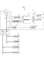
まず、図1を参照して、本実施形態に係る電気機器管理システム100の構成について説明する。図1に示すように、電気機器管理システム100は、電気機器管理装置1を備える。電気機器管理装置1は、ある特定の住戸に設置された複数の電気機器2の使用状態を管理する。電気機器2は、電力線3に接続されている。電力線3は、分電盤4に接続されており、分電盤4内でさらにブレーカー(主ブレーカー41及びブレーカー42等)に接続されている。分電盤4から電力線3を介して複数の電気機器2各々に電力が供給されている。電気機器管理装置1も、電力線3に接続されている。
First, with reference to FIG. 1, the structure of the electric
電気機器管理装置1と各電気機器2とは、電力線3を介して電力線通信が可能となっている。
The electric
図1に示すように、電気機器管理装置1は、電力計測部10と、運転機器検出部11と、履歴保存部12と、表示部13と、操作部14と、情報生成部15と、を備える。
As shown in FIG. 1, the electrical
電力計測部10は、電力線3を流れる電流を検出する電流センサの出力等に基づいて、住戸全体の使用電力量を計測する。
The
運転機器検出部11は、上記電力線通信により、住戸に設置された複数の電気機器2各々が、現在運転中であるか否かを示す運転機器情報を検出する。運転機器検出部11は、電気機器2の個々の運転中の使用電力量も保持している。
The driving device detection unit 11 detects driving device information indicating whether or not each of the plurality of
履歴保存部12は、電力計測部10によって計測された使用電力量の推移に関する情報と、運転機器検出部11によって検出された運転機器情報とを対応付けて記憶する。
The
表示部13には、画像を表示する表示画面が設けられている。操作部14は、ユーザの操作入力を受け付けるマウスやキーボード等の入力インターフェイスである。
The
情報生成部15は、CPU及びメモリ(いずれも不図示)を備える。CPUがメモリに格納されたプログラムを実行することにより、情報生成部15の機能が実現される。
The
情報生成部15は、まず、履歴保存部12によって保存された使用電力量の推移に関する情報を読み出して、例えばその推移を表すグラフを表示部13に表示させる。その表示を見たユーザが、操作部14を操作して、表示部13によって表示された使用電力量の推移を示すグラフの中から、特定の部分を指定すると、情報生成部15は、履歴保存部12から、特定の部分に対応する運転機器情報を読み出して、読み出された運転機器情報に基づいて、特定の部分に対応する時間帯において使用電力量が低減するように電気機器2の運転スケジュールを調整するための調整用情報を生成する。
First, the
生成される調整用情報には、電気機器2の省電力運転への変更に関する情報、電気機器2の運転時間の変更に関する情報及び電気機器2の運転の停止に関する情報の少なくとも1つが含まれている。
The generated adjustment information includes at least one of information related to the change of the
例えば、特定の部分に対応する時間帯で運転中であった電気機器2のうち、省電力運転が可能であるものが含まれていた場合には、その電気機器2を省電力運転に変更すれば、その時間帯の使用電力量を低減することができるため、情報生成部15は、その電気機器2の情報を調整用情報に含める。
For example, if an
また、特定の部分に対応する時間帯で運転中であった電気機器2のうち、運転時間を変更することができる電気機器2が含まれていた場合には、情報生成部15は、その電気機器2の情報を調整用情報に含める。
In addition, when the
また、特定の部分に対応する時間帯で運転中であった電気機器2のうち、運転を停止しても格別問題ない電気機器2が含まれていた場合には、情報生成部15は、その電気機器2の情報を調整用情報に含める。
In addition, when the
情報生成部15は、優先して運転すべき電気機器2の優先度が登録された優先度テーブルを有している。例えば、運転を停止するのが望ましくない電気機器2や、運転時間を変更することが望ましくない電気機器2(例えば、生活の基本である冷蔵庫、炊飯器等の調理器、緊急性の高い警報機器や、常時通電しておく必要のある電話機等の通信機器)については、優先度が高めに設定されている。また、省電力運転が可能な電気機器2(例えば、エアコン)については、優先度は低めに設定されている。また、運転を停止しても格別問題のない電気機器2や、運転時間を変更しても格別問題のない電気機器2(例えば、趣味に用いられる機器や、単発的に用いられる機器)については、優先度は低めに設定されている。
The
なお、照明機器など夜間は必須であるが、昼間は必須でない電気機器2については、時間帯に応じて優先度を変更することができる。
In addition, although it is essential at night, such as a lighting apparatus, about the
情報生成部15は、この優先度テーブルを参照して、特定の部分に対応する時間帯で運転中であった電気機器2の順位づけを行う。情報生成部15は、この順位に従って、特定の部分に対応する時間帯で運転中であった電気機器2のうち、省電力運転への変更、運転時間の変更、運転の停止が可能な電気機器2を選択可能な調整用情報を生成する。
The
また、この実施の形態では、運転機器検出部11は、運転中の電気機器2の個別の使用電力量を、あらかじめ取得し、その使用電力量を運転機器情報に含めて、履歴保存部12に保存している。情報生成部15は、特定の部分に対応する時間帯で運転中であった電気機器2各々の個別の使用電力量を、履歴保存部12から読み出して、それらの加算値を求めることができる。その加算値が所定の閾値以上である場合、情報生成部15は、電気機器2の順位に従って、省電力運転への変更、運転時間の変更、運転の停止を行った場合に、予想される全体の使用電力量が所定の閾値を下回る条件を求める。
Further, in this embodiment, the driving device detection unit 11 acquires in advance the individual power consumption of the
例えば、特定の部分に対応する時間帯で運転中であった電気機器2が、エアコン、加湿器、ドライヤー、炊飯器、テレビであったとする。この場合、電気機器2の優先順位は、例えば、炊飯器、テレビ、エアコン、加湿器、ドライヤーとなる。この場合、情報生成部15は、個々の機器の使用電力量に基づいて、優先順位に従って、ドライヤーを停止したり、加湿器の運転時間を変更したり、エアコンの温度を冷房であれば高めに設定したりしたときに予想される全体の予想使用電力量を求め、その値が所定の閾値を下回る条件を求める。その条件が、調整用情報となる。
For example, it is assumed that the
このようにして生成された調整用情報は、表示部13に出力される。表示部13は、調整用情報を、ユーザに対するアドバイス情報として表示する。この表示を見たユーザは、その情報を見て、その時間帯になったときに、ドライヤーの運転をしないようにしたり、加湿器の運転時間を変更したり、エアコンの温度を高めに設定したりする。このようにすれば、その時間帯の全体の消費電力量を低減することが可能となる。
The adjustment information generated in this way is output to the
次に、電気機器管理装置1の動作について説明する。
Next, the operation of the electric
図2には、電気機器管理装置1の情報生成部15によって実行される処理のフローチャートが示されている。この処理の前提として、電力計測部10により約1週間分の使用電力量が計測されて履歴保存部12に保存されているものとし、運転機器検出部11により1週間分の運転機器情報が検出され、履歴保存部12に保存されているものとする。
FIG. 2 shows a flowchart of processing executed by the
図2に示すように、まず、情報生成部15は、操作部14の操作入力により、期日が指定されるまで待つ(ステップS1;No)。操作部14の操作入力により、期日が指定されると(ステップS1;Yes)、情報生成部15は、指定された期日の使用電力量の時系列データを、履歴保存部12から読み込む(ステップS2)。続いて、情報生成部15は、読み込んだ使用電力量の時系列データを、表示部13に表示させる(ステップS3)。図3には、表示部13に表示される使用電力量の時系列データの一例が示されている。
As shown in FIG. 2, first, the
続いて、情報生成部15は、操作部14の操作入力により、特定の部分が指定されるまで待つ(ステップS4;No)。操作部14の操作入力により、特定の部分が指定されると(ステップS4;Yes)、情報生成部15は、指定された特定の部分に対応する時間帯の運転機器情報を、履歴保存部12から読み込む(ステップS5)。続いて、情報生成部15は、読み出された電気機器情報に基づいて、使用電力量が低減するような電気機器の運転スケジュールの調整用情報を生成する(ステップS6)。
Subsequently, the
ここで、例えば図4に示すように、ユーザが、使用電力量が閾値S1を超える期間t1、t2における電力を抑えたいと考えたとする。すると、ユーザは、操作部14を操作して、表示された使用電力量の推移のグラフのうち、期間t1、t2を指定入力する。すると、情報生成部15は、期間t1、t2に係る電気機器情報を履歴保存部12から読み出す。
Here, for example, as illustrated in FIG. 4, it is assumed that the user wants to suppress the power in the periods t1 and t2 in which the power consumption exceeds the threshold S1. Then, the user operates the
ここで、期間t1、t2において稼動中であった電気機器2が、加湿器、ドライヤー、テレビ、エアコンであったとする。この場合、各電気機器2の優先順位は、例えば、テレビ、加湿器、エアコン、ドライヤーとなる。情報生成部15は、優先順位順に、ドライヤーの停止、エアコンの温度変更などを行い、この時間帯の使用電力量が閾値S1を下回る条件を見つけ出す。その条件を見つけ出すと、情報生成部15は、その条件に関する情報を調整用情報として生成する。
Here, it is assumed that the
また、例えば、図4に示すように、ユーザが、操作部14を操作して、表示された使用電力量の推移のグラフのうち、期間t3を指定入力したものとする。すると、情報生成部15は、期間t3に係る電気機器情報を履歴保存部12から読み出す。
Further, for example, as illustrated in FIG. 4, it is assumed that the user operates the
ここで、期間t3において稼動中であった電気機器2が、掃除機だけであったとする。この場合、情報生成部15は、掃除機が稼働していた旨の情報を調整用情報として生成する。このように、ユーザは、使用電力が閾値を上回っているか否かに関わらず、表示された使用電力量の推移のグラフから任意の部分を指定することが可能である。
Here, it is assumed that the
なお、この実施の形態では、常時通電している冷蔵庫、通信機器等については、調整用情報に含まれる電気機器2から予め除外されている。
In this embodiment, the refrigerator, communication device, and the like that are always energized are excluded in advance from the
続いて、情報生成部15は、生成した調整用情報を表示部13に出力する(ステップS7)。表示部13は、入力した調整用情報を表示する。
Subsequently, the
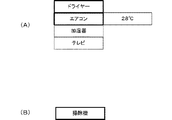
図5(A)には、ユーザが期間t1、t2を指定したときに表示部13に表示される調整用情報の一例が示されている。図5(A)に示すように、運転を中止すべきドライヤーや、温度を28℃に設定すべきエアコンは、強調表示されている。
FIG. 5A shows an example of the adjustment information displayed on the
また、図5(B)には、ユーザが期間t3を指定したときに表示部13に表示される調整用情報の一例が示されている。図5(B)に示すように、掃除機のみが強調表示される。
FIG. 5B shows an example of adjustment information displayed on the
ユーザは、表示部13に表示された調整用情報を見て、調整用情報に基づく運転スケジュールに従って電気機器2を使用する。具体的には、ユーザは、指定された期間t1に対応する時間帯に差し掛かった場合に、掃除機の使用を差し控え、指定された期間t2、t3に対応する時間帯に差し掛かった場合に、ドライヤーの使用を差し控え、エアコンの温度を28℃に設定する。このようにすれば、その日の使用電力量の推移は、図6に示すようになる。図6に示すように、期間t1、t2、t3における使用電力量は、以前に比べ低減されており、特に、期間t1、t2における使用電力量は、ほぼ閾値S1以下となっている。
The user looks at the adjustment information displayed on the
以上詳細に説明したように、この実施の形態によれば、住戸全体の使用電力量の推移をユーザに見せることができるので、電力使用に関するユーザの意識を高めることができる。さらに、電力使用に関する意識が高まったユーザが操作入力により特定の部分を指定すると、特定の部分に対応する時間帯の運転機器情報に基づいて、特定の時間帯における使用電力量が低減するような電気機器2の運転スケジュールを調整するための調整用情報が生成される。この調整用情報は、表示部13に表示される。ユーザがこの調整用情報を見て、調整用情報に基づく電気機器2の運転スケジュールに従って、電気機器2を運転すれば、その時間帯の消費電力を低減することができる。すなわち、この実施の形態によれば、電力使用に関するユーザの意識を高め、省エネルギー化を実現するための行動をユーザに具体的に促すことができるうえ、その行動に沿った省エネルギー化を実現することができる。
As described above in detail, according to this embodiment, since the transition of the power consumption of the entire dwelling unit can be shown to the user, the user's awareness regarding the power usage can be enhanced. Furthermore, when a user who has increased awareness about power use designates a specific part by an operation input, the amount of power used in the specific time period is reduced based on the driving device information of the time period corresponding to the specific part. Adjustment information for adjusting the operation schedule of the
実施の形態2.
次に、この発明の実施の形態2について説明する。
Next, a second embodiment of the present invention will be described.
図7に示すように、この実施の形態に係る電気機器管理装置1は、通信部19と制御部20をさらに備える点が、上記実施の形態1に係る電機機器管理装置1と異なっている。
As shown in FIG. 7, the electrical
通信部19は、電力線3と接続されている。通信部19は電力線3を介して電気機器2等と電力線通信を行う。
The
制御部20は、情報生成部15によって生成された調整用情報に基づいて、調整用情報に基づく運転スケジュールを生成し、その運転スケジュールに従って、電気機器2の運転を制御する。この制御は、通信部19及び電力線3を介した電力線通信によって行われる。すなわち、上記実施の形態1では、表示部13にアドバイス情報を表示して、ユーザに調整用情報に係る電気機器の運転スケジュールに従って、電気機器2を使用することにより、省エネルギー化を実現するための行動をとるように促していたのに留まるのに対し、この実施の形態では、情報生成部15によって生成された調整用情報を用いて、制御部20が、電気機器2の運転を自動制御する。
The
制御部20は、上記実施の形態と同様に、ユーザによって指定された特定の部分に対応する時間帯において全体の使用電力量が低減するような運転スケジュールに従って、電気機器2の運転を制御する。したがって、この実施の形態においても、電力使用に関するユーザの意識を高め、省エネルギー化を実現するための行動をユーザに具体的に促すことができるうえ、その行動に沿った省エネルギー化を実現することができる。
Similar to the above-described embodiment, the
ところで、ユーザの生活リズムは日によって異なるのが通常であり、帰宅時刻も日によって異なるのが一般的である。この場合、制御部20は、調整用情報に基づく運転スケジュールを、帰宅時刻に応じてずらすようにしてもよい。
By the way, the user's life rhythm usually varies from day to day, and the time to go home generally varies from day to day. In this case, the
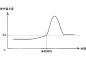
帰宅時間は、電力計測部10によって計測される全体の使用電力量に基づいて検出することが可能である。図8に示すように、電力計測部10によって計測される全体の使用電力量が閾値S2を超えた時点を、帰宅時刻とすることができる。制御部20は、この使用電力量が閾値S2を超える時点(帰宅時刻)を基準として、調整用情報に基づく運転スケジュールに従った電気機器の運転の制御を開始する。このようにすれば、ユーザの日々の生活リズムの変化に応じた適切な運用スケジュールに基づく電気機器2の使用が可能となる。
The return home time can be detected based on the total power consumption measured by the
なお、制御部20は、電力計測部10によって計測される使用電力量が閾値S2を超える時点が、通常よりも所定期間以上遅延する場合に、調整用情報に基づく運転スケジュールに従った電気機器の制御を停止するようにしてもよい。
In addition, the
実施の形態3.
次に、この発明の実施の形態3について説明する。
Next, a third embodiment of the present invention will be described.
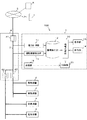
図9に示すように、この実施の形態に係る電気機器管理装置1の構成は、上記実施の形態2に係る電気機器管理装置1の構成と同じである。
As shown in FIG. 9, the configuration of the electrical
この実施の形態では、電力線3は、外部の通信ネットワーク5に接続されている。通信ネットワーク5には、サーバ6が接続されている。
In this embodiment, the
サーバ6は、平均的な使用電力量の推移に関する情報を、世帯構成毎に管理している。制御部20は、通信部19を介して住戸に対応する世帯構成と同一の世帯構成における平均的な使用電力量の推移に関する情報を、通信ネットワーク5を介して受信して、履歴保存部12に保存する。
The
情報生成部15は、履歴保存部12によって保存された使用電力量の推移に関する情報を表示部13に表示させる際に、平均的な使用電力量の推移に関する情報も読み出して、両者を表示部13に比較表示させる。このような比較表示を見れば、ユーザは、自らの家庭が電力を消費しすぎであるのか否かを容易に認識することができるようになるので、ユーザの省エネルギー化の意識をより明確に喚起させることができる。
When the
また、図9には、ユーザが所持する携帯電話等のネットワーク端末7も示されている。ネットワーク端末7は、通信ネットワーク5に無線で接続可能であり、通信ネットワーク5及び通信部19を介して、電気機器管理装置1の制御部20と通信可能である。
FIG. 9 also shows a
ユーザは、ネットワーク端末7を用いて、電気機器管理装置1を遠隔操作することが可能である。通信部19は、ネットワーク端末7から送信される制御停止指令の指令情報を、通信ネットワーク5を介して受信する。制御部20は、通信部19を介して制御停止指令の指令情報を受信すると、調整用情報に基づく運転スケジュールに従った電気機器2の制御を停止する。
The user can remotely operate the electrical
このようにすれば、来客などがあって電力制限を行うべきでない場合などに、制御部20による電気機器2の制御を停止して、消費電力の低下による不都合を生じさせないようにすることができる。
In this way, when there is a visitor or the like and the power limit should not be performed, the control of the
なお、同様に、ネットワーク端末7から送信される制御開始指令の指令情報を、通信ネットワーク5を介して通信部19に送信し、制御部20に、調整用情報に基づく運転スケジュールに従った電気機器2の制御を開始させるようにしてもよい。
Similarly, the command information of the control start command transmitted from the
なお、上記各実施の形態では、個々の電気機器2の使用電力量を、電力線通信を介して、電気機器2から取得したが、本発明はこれには限られない。例えば、操作部14を介して、個々の電気機器2の使用電力量を入力できるようにしてもよい。入力された個々の電気機器2の使用電力量は、履歴保存部12に保存され、上記各実施の形態と同様にして、調整用情報の生成に用いられる。
In each of the above-described embodiments, the amount of power used by each
また、履歴保存部12に、電気機器2各々の使用電力量の基準データを電気機器の種別毎に記憶しておくようにしてもよい。情報生成部15は、履歴保存部12に保存された基準データを、住戸に設置された電気機器2の容量に基づく補正係数を用いて補正したデータを、電気機器2の使用電力量として用いる。
The
また、サーバ6において、複数の電気機器2各々の使用電力量を管理しておき、制御部20が、必要に応じてサーバ6から家屋に設置された電気機器2の使用電力量を、通信ネットワーク5を介して受信して、履歴保存部12に保存しておくようにしてもよい。
Further, the
なお、表示部13に表示されるアドバイス情報としては、より具体的に、「××時〜××時の間は、エアコンの温度を28℃に設定してください。」というアドバイスであってもよい。
More specifically, the advice information displayed on the
なお、上記実施の形態において、実行されるプログラムは、フレキシブルディスク、CD−ROM(Compact Disk Read-Only Memory)、DVD(Digital Versatile Disk)、MO(Magneto-Optical Disk)等のコンピュータ読み取り可能な記録媒体に格納して配布し、そのプログラムをインストールすることにより、上述の処理を実行するシステムを構成することとしてもよい。 In the above embodiment, the program to be executed is a computer-readable recording such as a flexible disk, a CD-ROM (Compact Disk Read-Only Memory), a DVD (Digital Versatile Disk), and an MO (Magneto-Optical Disk) A system that executes the above-described processing may be configured by storing and distributing the program on a medium and installing the program.
また、プログラムをインターネット等の通信ネットワーク上の所定のサーバ装置が有するディスク装置等に格納しておき、例えば、搬送波に重畳させて、ダウンロード等するようにしてもよい。 Further, the program may be stored in a disk device or the like of a predetermined server device on a communication network such as the Internet, and may be downloaded, for example, superimposed on a carrier wave.
また、上述の機能を、OS(Operating System)が分担して実現する場合又はOSとアプリケーションとの協働により実現する場合等には、OS以外の部分のみを媒体に格納して配布してもよく、また、ダウンロード等してもよい。 In addition, when the above functions are realized by sharing an OS (Operating System), or when the functions are realized by cooperation between the OS and an application, only the part other than the OS may be stored in a medium and distributed. You may also download it.
なお、この発明は、上記実施の形態及び図面によって限定されるものではない。この発明の要旨を変更しない範囲で実施の形態及び図面に変更を加えることができるのはもちろんである。 In addition, this invention is not limited by the said embodiment and drawing. It goes without saying that the embodiments and the drawings can be modified without changing the gist of the present invention.
1 電気機器管理装置
2 電気機器
3 電力線
4 分電盤
41 主ブレーカー
42 ブレーカー
5 通信ネットワーク
6 サーバ
7 ネットワーク端末
10 電力計測部
11 運転機器検出部
12 履歴保存部
13 表示部
14 操作部
15 情報生成部
19 通信部
20 制御部
100 電気機器管理システム
DESCRIPTION OF
Claims (14)
前記住戸に設置された複数の電気機器各々が、現在運転中であるか否かを示す運転機器情報を検出する運転機器検出部と、
前記使用電力計測部によって計測された使用電力量の推移に関する情報と、前記運転機器検出部によって検出された前記運転機器情報とを対応付けて保存する履歴保存部と、
前記履歴保存部に保存された前記使用電力量の推移に関する情報を表示する表示部と、
前記表示部によって表示された前記使用電力量の推移に関する情報の中から、操作入力により、特定の部分を指定する指定部と、
前記履歴保存部に保存された前記特定の部分に対応する前記運転機器情報に基づいて、前記特定の部分に対応する時間帯において前記使用電力量が低減するように前記電気機器の運転スケジュールを調整するための調整用情報を生成する情報生成部と、
前記調整用情報に基づく前記運転スケジュールに従って、前記電気機器の運転を制御する制御部と、
を備え、
前記制御部は、
前記使用電力計測部によって計測される住戸全体の使用電力量が所定レベルを超える時点を前記住戸の居住者の帰宅時刻として検出し、検出した帰宅時刻を基準として、前記調整用情報に基づく前記運転スケジュールに従った前記電気機器の運転の制御を開始し、
前記使用電力計測部によって計測される住戸全体の使用電力量が所定レベルを超える時点が、所定期間以上遅延する場合に、
前記調整用情報に基づく前記運転スケジュールに従った前記電気機器の制御を停止する、
電気機器管理装置。 A power consumption measurement unit that measures the power consumption of the entire dwelling unit,
Each of the plurality of electric devices installed in the dwelling unit is a driving device detection unit that detects driving device information indicating whether the device is currently operating,
A history storage unit that stores information related to the transition of the power consumption measured by the power consumption measurement unit and the driving device information detected by the driving device detection unit;
A display unit for displaying information on the transition of the used electric energy stored in the history storage unit;
Among the information on the transition of the power consumption displayed by the display unit, a designation unit that designates a specific part by an operation input,
Based on the operating equipment information corresponding to the specific part stored in the history storage unit, the operation schedule of the electrical equipment is adjusted so that the power consumption is reduced in the time zone corresponding to the specific part An information generating unit for generating adjustment information for
In accordance with the operation schedule based on the adjustment information, a control unit that controls the operation of the electric device;
With
The controller is
The time when the power consumption of the entire dwelling unit measured by the power consumption measuring unit exceeds a predetermined level is detected as the return time of the resident of the dwelling unit, and the operation based on the adjustment information based on the detected return time start the control of operation of the electrical equipment in accordance with the schedule,
When the time when the power consumption of the whole dwelling unit measured by the power consumption measuring unit exceeds a predetermined level is delayed for a predetermined period,
Stopping the control of the electrical device according to the operation schedule based on the adjustment information;
Electrical equipment management device.
前記調整用情報を、ユーザに対するアドバイス情報として表示する、
ことを特徴とする請求項1に記載の電気機器管理装置。 The display unit
Displaying the adjustment information as advice information to the user;
The electrical equipment management apparatus according to claim 1.
前記制御部は、
前記指令情報受信部で受信された指令情報に従って、前記調整用情報に基づく前記運転スケジュールに従った前記電気機器の制御の開始及び停止を行う、
ことを特徴とする請求項1又は2に記載の電気機器管理装置。 A command information receiving unit that receives command information from the network terminal via the communication network is further provided.
The controller is
According to the command information received by the command information receiving unit, start and stop the control of the electrical equipment according to the operation schedule based on the adjustment information,
The electrical equipment management apparatus according to claim 1 or 2 , characterized in that.
前記電気機器の省電力運転への変更に関する情報、前記電気機器の運転時間の変更に関する情報及び前記電気機器の運転の停止に関する情報の少なくとも1つが含まれる、
ことを特徴とする請求項1乃至3のいずれか一項に記載の電気機器管理装置。 The adjustment information includes
At least one of information related to the change to the power saving operation of the electric device, information related to a change in the operation time of the electric device, and information related to the stop of the operation of the electric device is included,
The electrical equipment management apparatus according to any one of claims 1 to 3 .
前記情報生成部は、
前記優先順位記憶部に記憶された優先順位に従って、前記調整用情報を生成する、
ことを特徴とする請求項1乃至4のいずれか一項に記載の電気機器管理装置。 A priority order storage unit for storing the priority order of the electrical equipment to be preferentially operated;
The information generator is
Generating the adjustment information according to the priority order stored in the priority order storage unit;
Electrical equipment management device according to any one of claims 1 to 4, characterized in that.
前記情報生成部は、
前記特定の部分に対応する前記運転機器情報に係る前記電気機器の消費電力に関する情報を、前記機器別電力記憶部から読み出し、読み出された情報に基づいて、前記調整用情報を生成する、
ことを特徴とする請求項1乃至5のいずれか一項に記載の電気機器管理装置。 A power storage unit for each device that stores information on power consumption of each of the plurality of electrical devices;
The information generator is
Read the information on the power consumption of the electrical equipment related to the operating equipment information corresponding to the specific portion from the power storage unit by equipment, and generate the adjustment information based on the read information,
Electrical equipment management device according to any one of claims 1 to 5, characterized in that.
前記機器別電力記憶部は、前記機器別電力入力部によって入力された前記複数の電気機器各々の消費電力に関する情報を記憶する、
ことを特徴とする請求項6に記載の電気機器管理装置。 A device-specific power input unit that inputs information on power consumption of each of the plurality of electrical devices by operation input,
The device-specific power storage unit stores information regarding power consumption of each of the plurality of electric devices input by the device-specific power input unit.
The electrical equipment management apparatus according to claim 6 .
前記機器別電力記憶部は、前記機器別電力検出部によって検出された前記複数の電気機器各々の消費電力に関する情報を記憶する、
ことを特徴とする請求項6に記載の電気機器管理装置。 A device-specific power detection unit that detects information on the power consumption of each of the plurality of electrical devices;
The device-specific power storage unit stores information on power consumption of each of the plurality of electrical devices detected by the device-specific power detection unit,
The electrical equipment management apparatus according to claim 6 .
前記機器別電力記憶部は、前記機器別電力情報受信部によって受信された前記複数の電気機器各々の消費電力に関する情報を記憶する、
ことを特徴とする請求項6に記載の電気機器管理装置。 A device-specific power information receiving unit that receives information on the power consumption of each of the plurality of electrical devices via a communication network,
The device-specific power storage unit stores information related to power consumption of each of the plurality of electrical devices received by the device-specific power information reception unit.
The electrical equipment management apparatus according to claim 6 .
前記複数の電気機器各々の消費電力に関する情報の基準データを前記電気機器の種別毎に記憶しており、
前記情報生成部は、
前記機器別電力記憶部に記憶された基準データを、前記住戸に設置された前記電気機器の容量に基づいて補正したデータを、前記電気機器の消費電力に関する情報として用いる、
ことを特徴とする請求項6に記載の電気機器管理装置。 The device-specific power storage unit is
Reference data of information regarding power consumption of each of the plurality of electrical devices is stored for each type of the electrical device,
The information generator is
Using the reference data stored in the device-specific power storage unit, data corrected based on the capacity of the electrical device installed in the dwelling unit, as information related to the power consumption of the electrical device,
The electrical equipment management apparatus according to claim 6 .
前記表示部は、
前記履歴保存部によって保存された前記使用電力量の推移に関する情報と、前記平均的な前記使用電力量の推移に関する情報とを比較表示する、
ことを特徴とする請求項1乃至10のいずれか一項に記載の電気機器管理装置。 Further comprising an average information receiving unit for receiving information on the transition of average power consumption in the same household configuration as the household configuration corresponding to the dwelling unit via a communication network;
The display unit
Comparing and displaying the information on the transition of the used power amount stored by the history storage unit and the information on the average transition of the used power amount,
Electrical equipment management device according to any one of claims 1 to 1 0, characterized in that.
前記電気機器管理装置に接続されたサーバと、
を備える電気機器管理システム。 The electrical equipment management device according to any one of claims 1 to 11,
A server connected to the electrical equipment management device;
An electrical equipment management system comprising:
前記住戸に設置された複数の電気機器各々が、現在運転中であるか否かを示す運転機器情報を検出する運転機器検出工程と、
前記使用電力計測工程において計測された使用電力量の推移に関する情報と、前記運転機器検出工程において検出された前記運転機器情報とを対応付けて記憶する履歴保存工程と、
前記履歴保存工程において保存された前記使用電力量の推移に関する情報を表示する表示工程と、
前記表示工程において表示された前記使用電力量の推移に関する情報の中から、操作入力により、特定の部分を指定する指定工程と、
前記履歴保存工程において保存された前記特定の部分に対応する前記運転機器情報に基づいて、前記特定の部分に対応する時間帯において前記使用電力量が低減するように前記電気機器の運転スケジュールを調整するための調整用情報を生成する情報生成工程と、
前記調整用情報に基づく前記運転スケジュールに従って、前記電気機器の運転を制御する制御工程と、
を含み、
前記制御工程では、
前記使用電力計測工程で計測される住戸全体の使用電力量が所定レベルを超える時点を前記住戸の居住者の帰宅時刻として検出し、検出した帰宅時刻を基準として、前記調整用情報に基づく前記運転スケジュールに従った前記電気機器の運転の制御を開始し、
前記使用電力計測工程で計測される住戸全体の使用電力量が所定レベルを超える時点が、所定期間以上遅延する場合に、
前記調整用情報に基づく前記運転スケジュールに従った前記電気機器の制御を停止する、
電気機器管理方法。 A power consumption measurement process that measures the power consumption of the entire dwelling unit,
Each of a plurality of electrical devices installed in the dwelling unit, a driving device detection step of detecting driving device information indicating whether or not currently operating,
A history storage step of storing information relating to the transition of the amount of power used measured in the power usage measurement step and the driving device information detected in the driving device detection step in association with each other,
A display step for displaying information on the transition of the used electric energy stored in the history storage step;
From the information regarding the transition of the power consumption displayed in the display step, a designation step for designating a specific part by an operation input,
Based on the operating device information corresponding to the specific part stored in the history storing step, the operation schedule of the electric device is adjusted so that the power consumption is reduced in a time zone corresponding to the specific part. An information generation step of generating adjustment information for
In accordance with the operation schedule based on the adjustment information, a control process for controlling the operation of the electrical device;
Including
In the control step,
Detecting the time when the power consumption of the entire dwelling unit measured in the power consumption measuring step exceeds a predetermined level as a return time of a resident of the dwelling unit, and using the detected return time as a reference, the operation based on the adjustment information start the control of operation of the electrical equipment in accordance with the schedule,
When the time when the power consumption of the entire dwelling unit measured in the power consumption measurement process exceeds a predetermined level is delayed for a predetermined period,
Stopping the control of the electrical device according to the operation schedule based on the adjustment information;
Electrical equipment management method.
住戸全体の使用電力量を計測する使用電力計測手段と、
前記住戸に設置された複数の電気機器各々が、現在運転中であるか否かを示す運転機器情報を検出する運転機器検出手段と、
前記使用電力計測手段によって計測された使用電力量の推移に関する情報と、前記運転機器検出手段によって検出された前記運転機器情報とを対応付けて保存する履歴保存手段と、
前記履歴保存手段によって保存された前記使用電力量の推移に関する情報を表示する表示手段と、
前記表示手段によって表示された前記使用電力量の推移に関する情報の中から、操作入力により、特定の部分を指定する指定手段と、
前記履歴保存手段によって保存された前記特定の部分に対応する前記運転機器情報に基づいて、前記特定の部分に対応する時間帯において前記使用電力量が低減するように前記電気機器の運転スケジュールを調整するための調整用情報を生成する情報生成手段と、
前記調整用情報に基づく前記運転スケジュールに従って、前記電気機器の運転を制御する制御手段と、
して機能させ、
前記制御手段が、
前記使用電力計測手段によって計測される住戸全体の使用電力量が所定レベルを超える時点を前記住戸の居住者の帰宅時刻として検出し、検出した帰宅時刻を基準として、前記調整用情報に基づく前記運転スケジュールに従った前記電気機器の運転の制御を開始し、
前記使用電力計測手段によって計測される住戸全体の使用電力量が所定レベルを超える時点が、所定期間以上遅延する場合に、
前記調整用情報に基づく前記運転スケジュールに従った前記電気機器の制御を停止する、
ように機能させるプログラム。 Computer
Power consumption measuring means for measuring the power consumption of the entire dwelling unit;
Each of a plurality of electrical devices installed in the dwelling unit, driving device detection means for detecting driving device information indicating whether or not currently operating,
History storage means for storing information related to the transition of power consumption measured by the power consumption measurement means and the driving equipment information detected by the driving equipment detection means in association with each other;
Display means for displaying information on the transition of the used electric energy stored by the history storage means;
Among the information on the transition of the used electric energy displayed by the display means, designation means for designating a specific part by an operation input;
Based on the operating equipment information corresponding to the specific part stored by the history storage unit, the operation schedule of the electrical equipment is adjusted so that the power consumption is reduced in the time zone corresponding to the specific part. Information generating means for generating adjustment information for
Control means for controlling the operation of the electric device according to the operation schedule based on the adjustment information;
To function,
The control means is
The time when the power consumption of the entire dwelling unit measured by the power consumption measuring means exceeds a predetermined level is detected as the return time of the resident of the dwelling unit, and the operation based on the adjustment information based on the detected return time start the control of operation of the electrical equipment in accordance with the schedule,
When the time when the power consumption of the entire dwelling unit measured by the power consumption measuring means exceeds a predetermined level is delayed for a predetermined period,
Stopping the control of the electrical device according to the operation schedule based on the adjustment information;
A program that makes it work.
Priority Applications (1)
| Application Number | Priority Date | Filing Date | Title |
|---|---|---|---|
| JP2010093568A JP5264821B2 (en) | 2010-04-14 | 2010-04-14 | Electrical device management apparatus, electrical device management system, electrical device management method, and program |
Applications Claiming Priority (1)
| Application Number | Priority Date | Filing Date | Title |
|---|---|---|---|
| JP2010093568A JP5264821B2 (en) | 2010-04-14 | 2010-04-14 | Electrical device management apparatus, electrical device management system, electrical device management method, and program |
Publications (2)
| Publication Number | Publication Date |
|---|---|
| JP2011221971A JP2011221971A (en) | 2011-11-04 |
| JP5264821B2 true JP5264821B2 (en) | 2013-08-14 |
Family
ID=45038849
Family Applications (1)
| Application Number | Title | Priority Date | Filing Date |
|---|---|---|---|
| JP2010093568A Active JP5264821B2 (en) | 2010-04-14 | 2010-04-14 | Electrical device management apparatus, electrical device management system, electrical device management method, and program |
Country Status (1)
| Country | Link |
|---|---|
| JP (1) | JP5264821B2 (en) |
Families Citing this family (5)
| Publication number | Priority date | Publication date | Assignee | Title |
|---|---|---|---|---|
| US8417391B1 (en) | 2011-12-15 | 2013-04-09 | Restore Nv | Automated demand response energy management system |
| US9807099B2 (en) | 2013-03-15 | 2017-10-31 | Google Inc. | Utility portals for managing demand-response events |
| US9810442B2 (en) | 2013-03-15 | 2017-11-07 | Google Inc. | Controlling an HVAC system in association with a demand-response event with an intelligent network-connected thermostat |
| US9595070B2 (en) * | 2013-03-15 | 2017-03-14 | Google Inc. | Systems, apparatus and methods for managing demand-response programs and events |
| WO2021010520A1 (en) * | 2019-07-16 | 2021-01-21 | 엘지전자 주식회사 | Device for providing power usage information on basis of artificial intelligence, and control method thereof |
Family Cites Families (11)
| Publication number | Priority date | Publication date | Assignee | Title |
|---|---|---|---|---|
| JP4051735B2 (en) * | 1997-10-09 | 2008-02-27 | 松下電器産業株式会社 | Information aggregation device and aggregation method |
| JP2003023730A (en) * | 2001-07-06 | 2003-01-24 | Mitsubishi Electric Corp | Energy utilization supporting device |
| JP2003116219A (en) * | 2001-10-09 | 2003-04-18 | Nihon Setsubi Kogyo Co Ltd | System and method for controlling quantity of working power, and computer-readable storage medium recording control program for quantity of working power |
| JP2003281228A (en) * | 2002-03-22 | 2003-10-03 | Ricoh Co Ltd | Management system and management method |
| JP3923860B2 (en) * | 2002-06-19 | 2007-06-06 | 株式会社東芝 | Electric management service method |
| JP2005093197A (en) * | 2003-09-17 | 2005-04-07 | Tokyo Gas Co Ltd | Cogeneration system |
| JP3902613B2 (en) * | 2004-06-28 | 2007-04-11 | 松村物産株式会社 | Cogeneration system, cogeneration system control method, and building |
| JP4274095B2 (en) * | 2004-09-29 | 2009-06-03 | 三菱電機株式会社 | Air conditioner management system |
| JP5302569B2 (en) * | 2008-04-17 | 2013-10-02 | パナソニック株式会社 | Power management system |
| JP5123039B2 (en) * | 2008-04-18 | 2013-01-16 | パナソニック株式会社 | Power management system |
| JP2009265972A (en) * | 2008-04-25 | 2009-11-12 | Tachibana Eletech Co Ltd | Use energy management system in building |
-
2010
- 2010-04-14 JP JP2010093568A patent/JP5264821B2/en active Active
Also Published As
| Publication number | Publication date |
|---|---|
| JP2011221971A (en) | 2011-11-04 |
Similar Documents
| Publication | Publication Date | Title |
|---|---|---|
| JP4501923B2 (en) | Home energy management system | |
| US9379547B2 (en) | Appliance control system | |
| JP2010075015A (en) | Demand control system for household electric appliance | |
| JP5264821B2 (en) | Electrical device management apparatus, electrical device management system, electrical device management method, and program | |
| JP5887549B2 (en) | Energy management device, energy management method, program | |
| JP5624172B1 (en) | Electric equipment management apparatus and program | |
| WO2014123076A1 (en) | Energy management system, energy management method, program, and controller | |
| JP2012222976A (en) | Power management device and power management method | |
| US10763671B2 (en) | Power management apparatus, power management system, power management method, and non-transitory storage medium | |
| JPWO2011111348A1 (en) | Use start section prediction apparatus and use start section prediction method | |
| KR20160140266A (en) | Method and apparatus for controlling power supply | |
| JP2007028036A (en) | Controller and method for controlling apparatus using it | |
| WO2015125531A1 (en) | Controller, network system, and method | |
| US9880579B2 (en) | Controller, method for controlling electrical device, device control system, and program | |
| JP5498517B2 (en) | Server device, home appliance control method and program | |
| JP6149651B2 (en) | Device management device, integrated device management device, device management system, device management method, and device management program | |
| WO2015159410A1 (en) | Device-controlling system, device-controlling apparatus, device, device-controlling method, and program | |
| JP5935003B2 (en) | Power control apparatus, power management system and program | |
| JP6098026B2 (en) | Power control system, program, and power control apparatus | |
| JP6625223B2 (en) | Electric device, power control system, power control method, and program | |
| JP6631870B2 (en) | Power management system, power management device, power management method, and program | |
| JP2013179481A (en) | Power supply switching unit, remote control, and photovoltaic power generation system | |
| WO2012124370A1 (en) | Load control device, control method therefor, and control program | |
| JP6701014B2 (en) | Control device, control method and program | |
| KR101933716B1 (en) | Energy use mode controlling method and energy management system using the same |
Legal Events
| Date | Code | Title | Description |
|---|---|---|---|
| A977 | Report on retrieval |
Free format text: JAPANESE INTERMEDIATE CODE: A971007 Effective date: 20120305 |
|
| A131 | Notification of reasons for refusal |
Free format text: JAPANESE INTERMEDIATE CODE: A131 Effective date: 20120313 |
|
| A521 | Request for written amendment filed |
Free format text: JAPANESE INTERMEDIATE CODE: A523 Effective date: 20120514 |
|
| A131 | Notification of reasons for refusal |
Free format text: JAPANESE INTERMEDIATE CODE: A131 Effective date: 20120925 |
|
| A521 | Request for written amendment filed |
Free format text: JAPANESE INTERMEDIATE CODE: A523 Effective date: 20121121 |
|
| TRDD | Decision of grant or rejection written | ||
| A01 | Written decision to grant a patent or to grant a registration (utility model) |
Free format text: JAPANESE INTERMEDIATE CODE: A01 Effective date: 20130402 |
|
| A61 | First payment of annual fees (during grant procedure) |
Free format text: JAPANESE INTERMEDIATE CODE: A61 Effective date: 20130430 |
|
| R150 | Certificate of patent or registration of utility model |
Ref document number: 5264821 Country of ref document: JP Free format text: JAPANESE INTERMEDIATE CODE: R150 Free format text: JAPANESE INTERMEDIATE CODE: R150 |
|
| R250 | Receipt of annual fees |
Free format text: JAPANESE INTERMEDIATE CODE: R250 |
|
| R250 | Receipt of annual fees |
Free format text: JAPANESE INTERMEDIATE CODE: R250 |
|
| R250 | Receipt of annual fees |
Free format text: JAPANESE INTERMEDIATE CODE: R250 |
|
| R250 | Receipt of annual fees |
Free format text: JAPANESE INTERMEDIATE CODE: R250 |
|
| R250 | Receipt of annual fees |
Free format text: JAPANESE INTERMEDIATE CODE: R250 |
|
| R250 | Receipt of annual fees |
Free format text: JAPANESE INTERMEDIATE CODE: R250 |
|
| R250 | Receipt of annual fees |
Free format text: JAPANESE INTERMEDIATE CODE: R250 |
|
| R250 | Receipt of annual fees |
Free format text: JAPANESE INTERMEDIATE CODE: R250 |
|
| R250 | Receipt of annual fees |
Free format text: JAPANESE INTERMEDIATE CODE: R250 |