JP5264388B2 - Program and printed circuit board design support method - Google Patents
Program and printed circuit board design support method Download PDFInfo
- Publication number
- JP5264388B2 JP5264388B2 JP2008246780A JP2008246780A JP5264388B2 JP 5264388 B2 JP5264388 B2 JP 5264388B2 JP 2008246780 A JP2008246780 A JP 2008246780A JP 2008246780 A JP2008246780 A JP 2008246780A JP 5264388 B2 JP5264388 B2 JP 5264388B2
- Authority
- JP
- Japan
- Prior art keywords
- region
- specifying
- gnd
- conductive
- circuit board
- Prior art date
- Legal status (The legal status is an assumption and is not a legal conclusion. Google has not performed a legal analysis and makes no representation as to the accuracy of the status listed.)
- Active
Links
Images


Classifications
-
- G—PHYSICS
- G06—COMPUTING; CALCULATING OR COUNTING
- G06F—ELECTRIC DIGITAL DATA PROCESSING
- G06F30/00—Computer-aided design [CAD]
- G06F30/30—Circuit design
- G06F30/39—Circuit design at the physical level
Description
本発明は、層間接続部材の配置箇所の決定の簡素化を図ったプリント基板設計支援用のプログラム及びプリント基板設計支援方法等に関する。 The present invention relates to a printed circuit board design support program, a printed circuit board design support method, and the like that are intended to simplify the determination of the location of an interlayer connection member.
近年、情報機器等の電子機器内に伝送される信号の高速化に伴い、該電子機器から放射される不要電磁波(放射ノイズ)が問題となってきている。この問題を解決するために、該電子機器内のプリント基板上の配線及び該配線に接続されたワイヤーハーネス、並びに該電子機器の筐体に対し、様々な放射ノイズの抑制設計が行われている。 In recent years, unnecessary electromagnetic waves (radiated noise) radiated from electronic devices have become a problem as the speed of signals transmitted in electronic devices such as information devices increases. In order to solve this problem, various radiation noise suppression designs have been performed on the wiring on the printed circuit board in the electronic device, the wire harness connected to the wiring, and the housing of the electronic device. .
このような放射ノイズの抑制設計技術の一つとして、プリント基板内の複数の導電層間を電気的に接続する層間接続部材(ビア)の配置を工夫する技術が提案されている(特許文献1及び特許文献2)。特許文献1には、プリント基板上の所定範囲内のビアの配置数を算出し、該ビアの配置数が所定数より少ない場合にその旨を報知する技術が開示されている。また、特許文献1には、所定間隔でビアが配置されているか否かを検出し、所定間隔で配置されていない場合にその旨を報知する技術も開示されている。
As one of such radiation noise suppression design techniques, a technique for devising the arrangement of interlayer connection members (vias) that electrically connect a plurality of conductive layers in a printed circuit board has been proposed (
また、放射ノイズの抑制設計技術の一つとして、高速信号の電流に対するリターン電流の経路を短縮しようとすることも行われている。ここで、リターン電流とは信号の帰還電流のことをいい、電源又はグラウンド(GND)領域で、かつ高速信号の電流の近傍をリターン電流が流れることが知られている。特許文献1には、グランド層に配線された電源線の位置でリターン電流が流れる経路をより短くすることのできるビアの配置を支援する技術が開示されている。特許文献2には、信号線のリターン電流ルートの層変更の必要性を判断すべき箇所(チェックポイント)を検出し、チェックポイントから指定距離の範囲内で、かつビアの配置されていない領域の合成領域を表示する技術が開示されている。 In addition, as one of the design techniques for suppressing radiated noise, an attempt has been made to shorten a return current path for a high-speed signal current. Here, the return current refers to a feedback current of a signal, and it is known that a return current flows in a power supply or ground (GND) region and in the vicinity of the current of a high-speed signal. Japanese Patent Application Laid-Open No. 2004-228561 discloses a technique that supports the arrangement of vias that can shorten the path through which a return current flows at the position of a power supply line wired in a ground layer. In Patent Document 2, a point (check point) where the necessity of changing the layer of the return current route of the signal line is to be detected is detected, and a region within a specified distance from the check point and where no via is arranged is detected. A technique for displaying a composite area is disclosed.
しかしながら、特許文献1及び特許文献2に記載の技術によれば、所定の報知及び領域表示がされた後に、ユーザが条件を満たすようにビアの追加配置を試みる必要があるが、その際にどの位置にビアを追加することが可能かを目視で判定しなければならない。そのため、ビアを追加配置することが可能な位置であることを判断するために多大な時間が必要とされ、更に、該判断のミス及び見落とし等が生じる可能性がある。また、リターン電流に関し、特許文献1の技術では、高速信号の配線のビア近傍のリターン電流が流れる経路に関しては考慮されていない。
However, according to the techniques described in
本発明は、ビアの追加配置が好ましい箇所の判断を簡易なものとすることができ、好ましくは高速信号の配線のビア近傍のリターン電流が流れる経路を短縮することができるプリント基板設計支援用のプログラム及びプリント基板設計支援方法等を提供することを目的とする。 According to the present invention, it is possible to simplify the determination of a place where an additional arrangement of vias is preferable, and it is preferable for a printed circuit board design support that can shorten a path through which a return current in the vicinity of a via of a high-speed signal wiring flows. An object is to provide a program, a printed circuit board design support method, and the like.
本願発明者は、前記課題を解決すべく鋭意検討を重ねた結果、以下に示す発明の諸態様に想到した。 As a result of intensive studies to solve the above problems, the present inventor has come up with various aspects of the invention described below.
本発明に係るプリント基板設計支援用のプログラムは、定電位が付与される導電領域を含む複数の導電層を有するプリント基板の設計をコンピュータに支援させるプログラムであって、コンピュータに、前記導電領域を前記複数の導電層毎に特定する導電領域特定ステップと、前記導電領域特定ステップにおいて特定した導電領域のうち、前記複数の導電層で互いに重なる領域を抽出する抽出ステップと、前記抽出ステップにおいて抽出した領域内で前記複数の導電層のうちの少なくとも2つを電気的に接続する第1の層間接続部材を特定する第1の層間接続部材特定ステップと、前記複数の導電層毎に所定の信号線を特定する信号線特定ステップと、前記信号線特定ステップにより特定された信号線のうち少なくとも2つを電気的に接続する第2の層間接続部材を特定する第2の層間接続部材特定ステップと、前記抽出ステップにおいて抽出した領域内で、前記第1の層間接続部材特定ステップにおいて特定した第1の層間接続部材から所定の範囲外にあり、かつ前記第2の層間接続部材特定ステップにおいて特定した第2の層間接続部材から所定の範囲内にある第2の領域を特定する第2の領域特定ステップと、を実行させることを特徴とする。 PCB design support for the program according to the present invention is a program for supporting the printed circuit board design having a plurality of conductive layers including a conductive region constant potential is applied to a computer, the computer, the conductive area a conductive region specifying step of specifying for each of the plurality of conductive layers, among the identified conducting region in the conductive region specifying step, an extraction step of extracting heavy Do that area together with the plurality of conductive layers, wherein the extraction step given at least two of the plurality of conductive layer extracted region and the first interlayer connection member specifying step of specifying a first interlayer connection member which electrically connects, for each of the plurality of conductive layers in And electrically connecting at least two of the signal lines identified by the signal line identifying step and the signal line identifying step A second interlayer connection member specifying step of specifying a second interlayer connection member, wherein at extracted region in the extraction step, the first interlayer connection member from the predetermined identified in the first interlayer connection member specifying step It is out of range, and be executed and a second area specifying step of specifying a second area in a predetermined range from the second interlayer connection members identified in said second interlayer connection member specifying step It is characterized by.
本発明によれば、層間接続部材の追加配置が好ましく、かつ追加配置を可能とする領域が明示されるので、ユーザは短時間で容易に適切な位置に層間接続部材を追加配置することができるようになる。 According to the present invention, the additional arrangement of the interlayer connection members is preferable, and the region enabling the additional arrangement is clearly specified, so that the user can easily arrange the interlayer connection members at appropriate positions in a short time. It becomes like this.
(第1の実施形態)
先ず、本発明の第1の実施形態について説明する。図1は、本発明の実施形態に係るプリント基板設計支援装置の構成を示す図である。本実施形態には、中央処理装置(CPU)10、主記憶装置11、表示装置12、入力装置13、外部記憶装置14、出力装置(プリンタ)15及びバス16が含まれている。
(First embodiment)
First, a first embodiment of the present invention will be described. FIG. 1 is a diagram showing a configuration of a printed circuit board design support apparatus according to an embodiment of the present invention. The present embodiment includes a central processing unit (CPU) 10, a
CPU10は、本装置の全体を制御する。主記憶装置11としては、読み出し専用記憶装置(ROM)及び/又はCPU10が計算処理時に一時的な読み書きを行う記憶装置(RAM)が用いられる。表示装置12としては、例えばブラウン管ディスプレイ又は液晶ディスプレイ等が用いられる。入力装置13としては、マウス及び/又はキーボード等が用いられる。外部記憶装置14は、ハードディスク、フレキシブルディスク、CD、DVD、MD等の記録媒体へのデータの読み書きに利用される。出力装置(プリンタ)15は表示装置12に出力された計算結果等を印刷する。バス16には、アドレスバス、データバス及び制御バス等が含まれ、情報を伝達する。また、外部記憶装置14には、処理プログラム141及びプリント基板に関わるレイアウト情報142等が記憶されている。レイアウト情報142には、プリント基板の層構成に関する情報、プリント基板に実装される部品の位置座標並びに端子が接続される導電部の形状及び大きさ等の部品情報並びに部品間配線の配線名及び配線図形を構成する各点の位置座標等の配線情報等が含まれる。
The
これらのCPU10、主記憶装置11、表示装置12、入力装置13、外部記憶装置14及び出力装置15はバス16を介して互いに接続されている。そして、CPU10の制御によりバス16を介して各装置間で制御情報及びデータ情報等の授受が行われる。
The
次に、プリント基板設計支援装置の機能的な構成について説明する。図2は、本発明の実施形態に係るプリント基板設計支援装置の機能構成を示す機能ブロック図である。本実施形態には、入力部20、外部記憶情報抽出部21、図形演算部22及び表示部23が含まれている。
Next, a functional configuration of the printed circuit board design support apparatus will be described. FIG. 2 is a functional block diagram showing a functional configuration of the printed circuit board design support apparatus according to the embodiment of the present invention. The present embodiment includes an
入力部20は、主に入力装置13から構成され、外部から入力された指示情報、及び条件情報等をCPU10に受け渡す。上記指示としては、例えばレイアウト情報142の読み出し、処理プログラム141の実行等が挙げられる。また、上記条件としては、例えば処理プログラム141等の実行に使用される条件(以下、検証条件)等が挙げられる。入力された情報は、例えば、CPU10により処理されるか、又はCPU10を介して主記憶装置11に記憶される。
The
外部記憶情報抽出部21は、主に外部記憶装置14から構成され、入力部20から処理プログラム141の実行命令が入力されると、その入力に従ってCPU10からの制御命令により外部記憶装置14中に記憶された処理プログラム141を抽出する。抽出されたプログラムは主記憶装置11内に格納される。また、外部記憶情報抽出部21は、入力部20からレイアウト情報読み出しの指示が入力されると、その入力に従ってCPU10からの制御命令により外部記憶装置14中に記憶されたレイアウト情報142を抽出する。抽出されたレイアウト情報は主記憶装置11内に格納される。
The external storage
図形演算部22は、主にCPU10及びこれが実行する処理プログラム141から構成され、入力部20から処理プログラム141の実行命令が入力されると、主記憶装置11の一部記憶領域を利用しながら、所定の図形演算処理を行う。図形演算処理としては、例えば、複数層にわたる図形の2次元的に重複する領域の抽出が挙げられる。この図形演算処理に際しては、主記憶装置11に記憶されている検証条件及びレイアウト情報142が参照される。
The
表示部23は、主に表示装置12から構成され、ユーザに検証条件の入力を促す画面、及び図形演算部22による処理の実行結果等を表示する。また、表示部23は、入力部20からレイアウト情報読み出しの指示が入力された場合には、プリント基板のレイアウト状況の表示も行う。
The
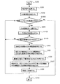
次に、プリント基板設計支援装置の動作について説明する。図3は、第1の実施形態に係るプリント基板設計支援装置の動作を示すフローチャートである。ここでは、各々がGNDの定電位が付与されるGND導電領域を含む複数の導電層が絶縁層を介して積層され、各GND導電領域がGNDビアを介して接続された構成のプリント基板の設計の際の動作について説明する。また、このプリント基板には、複数のGND配線が設けられており、各GND配線は、上記のGND導電領域の1又は2以上を用いて構成されているとする。 Next, the operation of the printed circuit board design support apparatus will be described. FIG. 3 is a flowchart showing the operation of the printed circuit board design support apparatus according to the first embodiment. Here, design of a printed circuit board having a configuration in which a plurality of conductive layers each including a GND conductive region to which a constant potential of GND is applied is stacked via an insulating layer, and each GND conductive region is connected via a GND via The operation at this time will be described. The printed circuit board is provided with a plurality of GND wirings, and each GND wiring is configured by using one or more of the GND conductive regions.
先ず、入力部20から処理プログラム141の実行指示が入力されると、外部記憶情報抽出部21が処理プログラム141を抽出し、主記憶装置11に格納する。そして、図形演算部22が処理プログラム141を実行し、処理が開始される(ステップS300)。また、図形演算部22が配線特定手段として、処理対象の所定の配線としてGND配線を特定する。なお、所定の配線として電源線が特定されてもよく、また、GND配線が特定されて以下の一連の処理が終了した後に、電源線が特定されて同様の処理が行われてもよい。
First, when an execution instruction for the
次いで、表示部23が検証条件の入力を促す画面を表示し、図形演算部22が、入力部20から入力された検証条件を取得する(ステップS301)。検証条件としては、GNDビア間の間隔が許容される最大値L1が入力される。以下、この最大値をGNDビア最大許容間隔値ということがある。
Next, the
ここで、GNDビア最大許容間隔値は、プリント基板の導電領域を流れる最も大きい周波数を持つ信号電流の波長(λ)の2分の1(λ/2)より小さくすることが好ましい。これは、プリント基板のGND又は電源導電領域上を流れるリターン電流とその反射した電流、又は別の信号に対するリターン電流が共振することを防ぐためである。実際には、1つのGND又は電源ビアから見てあらゆる方向のλ/2の距離の範囲内にGND又は電源ビアが配置されることが好ましい。一方で、現実的には、λ/10よりも小さい間隔で配置すれば放射ノイズを十分に抑制することが可能である。例えば、プリント基板上の最も高速な信号電流の周波数が1GHzの場合、プリント基板上でのその信号の波長は約15cmである。従って、GNDビア最大間隔は、その10分の1である1.5cmよりも小さい値とすればよい。ここで、より厳密には、周波数がf、誘電率がεr、透磁率がμr、光速がcの場合、プリント基板上での信号の波長λpは、λp=c/(f×√(εrμr))で計算することが可能である。従って、この計算式により計算された波長を用いるのもよい。 Here, it is preferable that the GND via maximum permissible interval value is smaller than half (λ / 2) of the wavelength (λ) of the signal current having the largest frequency flowing through the conductive region of the printed circuit board. This is to prevent the return current flowing on the GND or power supply conductive area of the printed circuit board and the reflected current thereof or the return current for another signal from resonating. In practice, it is preferable that the GND or the power supply via is disposed within a distance range of λ / 2 in any direction as viewed from one GND or the power supply via. On the other hand, in reality, it is possible to sufficiently suppress radiation noise if they are arranged at intervals smaller than λ / 10. For example, when the frequency of the fastest signal current on the printed circuit board is 1 GHz, the wavelength of the signal on the printed circuit board is about 15 cm. Therefore, the GND via maximum interval may be set to a value smaller than 1/10 of 1.5 cm. More precisely, when the frequency is f, the dielectric constant is ε r , the magnetic permeability is μ r , and the speed of light is c, the wavelength λ p of the signal on the printed circuit board is λ p = c / (f × √ (ε r μ r )). Therefore, the wavelength calculated by this calculation formula may be used.
その後、図形演算部22が、レイアウト情報142から複数のGND配線の名称(GND配線名)を抽出する(ステップS302)。これは、所定の配線としてGND配線が特定されているからである。
Thereafter, the
続いて、図形演算部22が、抽出した複数のGND配線名から検証対象とするGND配線名を任意に1つ選択する(ステップ303)。
Subsequently, the
次いで、図形演算部22が、導電領域特定手段として、検証対象とするGND配線(所定の配線)を構成するGND導電領域を導電層毎に特定する(ステップS304)。
Next, the
その後、図形演算部22が、抽出手段として、特定したGND導電領域の全てが厚さ方向で2次元的に重複する領域を領域Aとして抽出する(ステップS305)。即ち、特定したGND導電領域の全てが平面視で重なり合う領域を領域Aとして抽出する。
Thereafter, the
続いて、図形演算部22が、層間接続部材特定手段として、領域Aに含まれるGNDビアを特定する(ステップS306)。
Subsequently, the
次いで、図形演算部22が、領域A内で、ステップS306において特定したGNDビアの中心からGNDビア最大許容間隔値の半分の距離(L1×1/2)以下の領域を領域(GNDビア追加不要領域)Bとして抽出する(ステップS307)。この結果、特定したGNDビアからGNDビアの追加配置が好ましい範囲が明確になる。
Next, the
その後、図形演算部22及び表示部23が、明示手段として、ステップS305及びステップS307で夫々抽出された領域A及び領域Bを表示する(ステップS308)。
Thereafter, the
続いて、図形演算部22が、検証対象として選択されていないGND配線名があるか否かをレイアウト情報142から判断する(ステップS309)。つまり、まだ検証していないGND配線があるか否かの判断が行われる。
Subsequently, the
そして、図形演算部22は、選択されていないGND配線名がある場合は、ステップS303へ戻り、再びGND配線名を1つ選択する。一方、図形演算部22は、選択されていないGND配線名がない場合、即ち、すべてのGND配線の検証が済んでいる場合には、ステップS310へ進み、処理プログラム141を終了する。例えば、ステップS302において「GNDA」、「GNDB」というGND配線名が抽出されている場合で、「GNDA」のみについてステップS304からステップS308までの処理が終了しているときには、図形演算部22はステップS303へ戻る。そして、図形演算部及び表示部23が、未検証の「GNDB」についてのステップS304からステップS308までの処理を実行する。
Then, when there is a GND wiring name that has not been selected, the
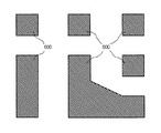
次に、プリント基板の具体例へ上述の動作を適用した場合の処理内容について説明する。図4は、プリント基板の具体例の構造を示す模式図である。この説明では、図4(e)に示すように、プリント基板の内部において、4つの導電層40、41、42及び43がこれらの間に絶縁層44を挟んで積層される部分への適用について説明する。
Next, processing contents when the above-described operation is applied to a specific example of a printed circuit board will be described. FIG. 4 is a schematic diagram showing the structure of a specific example of a printed circuit board. In this description, as shown in FIG. 4 (e), application to a portion where four
導電層40には、図4(a)に示すように、パターニングされたGND導電領域400がGND配線の一部として含まれる。そして、GND導電領域400には、上方及び/又は下方から複数のGNDビア401が接続される。また、GND導電領域400の隙間には、複数の配線402が設けられ、これらの端部には上方及び/又は下方から信号線ビア403が接続される。なお、配線402は、電源線又はGNDとは異なる電位の信号配線である。
As shown in FIG. 4A, the
導電層41には、図4(b)に示すように、パターニングされたGND導電領域410がGND配線の一部として含まれる。そして、GND導電領域410には、上方及び/又は下方から複数のGNDビア411が接続される。また、GND導電領域410には、下方から2つのGNDビア4110も接続される。導電層41には空間領域413も含まれる。空間領域413は、GND導電領域410の隙間に該当する。
As shown in FIG. 4B, the
導電層42には、図4(c)に示すように、パターニングされたGND導電領域420がGND配線の一部として含まれる。そして、GND導電領域420には、上方及び/又は下方から複数のGNDビア421が接続される。また、GND導電領域420には、上方及び下方から2つのGNDビア4210も接続される。また、GND導電領域420の隙間には、複数の配線422が設けられ、これらの端部には上方及び/又は下方から信号線ビア423が接続される。なお、配線422は、電源線又はGNDとは異なる電位の信号配線である。
As shown in FIG. 4C, the
導電層43には、図4(d)に示すように、パターニングされたGND導電領域430がGND配線の一部として含まれる。そして、GND導電領域430には、上方及び/又は下方から複数のGNDビア431が接続される。また、GND導電領域430には、上方から2つのGNDビア4310も接続される。また、GND導電領域430の隙間には、複数の配線432が設けられ、これらの端部には上方及び/又は下方から信号線ビア433が接続される。なお、配線432は、電源線又はGNDとは異なる電位の信号配線である。
As shown in FIG. 4D, the
なお、GNDビア401はGNDビア411の一部と共通し、GNDビア411の一部はGNDビア421の一部と共通し、GNDビア421の一部はGNDビア431の一部と共通する。また、信号線ビア403の一部は信号線ビア423と共通し、信号線ビア423の一部は信号線ビア433の一部と共通する。また、GNDビア4110、4210及び4310は導電層41〜43間で共通し、少なくともこれらによって導電層41〜43間の電気的導通が確保される。
Note that the GND via 401 is common with a part of the GND via 411, a part of the GND via 411 is common with a part of the GND via 421, and a part of the GND via 421 is common with a part of the GND via 431. Further, part of the signal line via 403 is common to the signal line via 423, and part of the signal line via 423 is common to part of the signal line via 433. The GND vias 4110, 4210, and 4310 are common between the
また、各導電層40〜43のうちのGND導電領域の隙間は配線又はビアが存在する部分を除き、その直下に位置する絶縁層44を露出する。また、空間領域413は、信号線ビア403、413及び433とGND導電領域410との接触を防止する。
In addition, the gap between the GND conductive regions of each of the
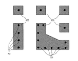
そして、このような部分に上記の動作を適用すると、次のようになる。図5は、第1の実施形態におけるステップS304の処理後の情報を示す模式図であり、図6は、第1の実施形態におけるステップS305の処理後の情報を示す模式図である。また、図7は、第1の実施形態におけるステップS306の処理後の情報を示す模式図であり、図8は、第1の実施形態におけるステップS307の処理後の情報を示す模式図である。 When the above operation is applied to such a portion, the following is obtained. FIG. 5 is a schematic diagram showing the information after the process of step S304 in the first embodiment, and FIG. 6 is a schematic diagram showing the information after the process of step S305 in the first embodiment. FIG. 7 is a schematic diagram showing information after the process of step S306 in the first embodiment, and FIG. 8 is a schematic diagram showing the information after the process of step S307 in the first embodiment.
上述のように、ステップS303では、選択されたGND配線名が1つ選択される。ここでは、GND導電領域400、410、420及び430を含むGND配線の名称が選択されたとする。この場合、ステップS304では、図5に示すように、GND導電領域400(図5(a))、GND導電領域410(図5(b))、GND導電領域420(図5(c))及びGND導電領域430(図5(d))が特定される。
As described above, in step S303, one selected GND wiring name is selected. Here, it is assumed that the name of the GND wiring including the GND
次いで、ステップS305では、図5に示すGND導電領域400、410、420及び430が投影され、図6に示すように、すべての導電層においてGND導電領域が2次元的に重複している領域がGND重複導電領域(領域A)600として抽出される。
Next, in step S305, the GND
その後、ステップS306では、図7に示すように、GNDビア401、411、421及び431並びにGNDビア4110、4210及び4310のうちでGND重複導電領域600と重なるものが重複GNDビア701として特定される。
Thereafter, in step S306, as shown in FIG. 7, the GND vias 401, 411, 421, and 431 and the
続いて、ステップS307では、重複GNDビア701からGNDビア最大許容間隔値の半分の距離以下の領域がGNDビア追加不要領域(領域B)として抽出される。即ち、図8に示すように、GND重複導電領域600と重複GNDビア701の中心を中心(基準)とする半径が「L1×1/2」の円800に含まれる領域の論理和がGNDビア追加不要領域801として抽出される。その一方で、GND重複導電領域600のうちでGNDビア追加不要領域801から外れる領域は、GNDビアの追加が好ましいGNDビア追加領域802となる。
Subsequently, in step S307, an area having a distance equal to or less than a half of the GND via maximum allowable interval value from the overlapping GND via 701 is extracted as a GND via addition unnecessary area (area B). That is, as shown in FIG. 8, the logical sum of the regions included in the
そして、ステップS308において、ステップS307の演算の結果が表示される。この表示では、GND重複導電領域600(領域A)及びGNDビア追加不要領域801(領域B)が区別可能に表示されることが好ましく、また、これらと区別可能にGNDビア追加領域802も表示されることが好ましい。例えば、これらの模様を相違させたり、色を相違させたり、区画線を表示させたりすることが好ましい。これにより、ユーザはGNDビア追加領域802を即座に認識することが可能となる。更に、この表示に際して、図形演算部22及び表示部23が、要求手段として、GNDビアのGNDビア追加領域802への追加配置を要求する表示を行うことが好ましい。これにより、ユーザがGNDビア追加領域802をより一層認識しやすくなり、GNDビア追加領域802へのGNDビアの追加洩れをより一層減少させることが可能となる。
In step S308, the calculation result of step S307 is displayed. In this display, the GND overlapping conductive region 600 (region A) and the GND via addition unnecessary region 801 (region B) are preferably displayed so as to be distinguishable, and the GND via
また、GNDビア追加領域802を重要度に応じて相違した色及び/又は模様で領域を表示させることも可能である。重要度を決める指標としては、例えば、各GNDビア追加領域802の面積又は外周又はその両方を採用することが考えられる。また、GNDビア追加領域802内の各構成点から見た領域の幅(領域の外縁又は内縁上の最近接点までの距離)を採用することも考えられる。また、重要度の段階としては、例えば、GNDビアを追加できない大きさの領域、GNDビアを追加する必要があるかどうかが不明な領域、明確にGNDビアを1個以上追加する必要のある領域の3段階等が考えられる。段階の分け方としては、GNDビアを配置できない領域と明確に配置できる領域が可視化されていればよい。例えば、面積を採用する場合には、GNDビア追加領域802の面積が各層におけるGNDビア周囲に配置する導電領域の面積よりも小さい場合、GNDビアを追加できない領域とする。そして、GNDビア追加領域802の面積が最大許容間隔値を直径に持つ円や一辺に持つ正方形の面積よりも小さい場合、GNDビアを配置する必要があるかどうかが不明な領域とする。更に、GNDビア追加領域802の面積が最大許容間隔値を直径に持つ円又は一辺に持つ正方形の面積よりも大きい場合、明確にGNDビアを1個以上配置する必要のある領域とする等が考えられる。
It is also possible to display the GND via
ユーザは、このような表示がされた後に、GND重複導電領域600のうちでGNDビア追加不要領域801から外れた領域(GNDビア追加領域802)に、GNDビアを追加又は移動すればよい。GNDビアが適切に追加された場合に再検証が行われると、ステップS308の処理後には、図9に示すように、GNDビア追加領域902がほとんど存在せず、GNDビア追加不要領域900によってGND重複導電領域600がほぼ占められた結果が得られる。この例では、2つのGNDビア901の追加が行われている。なお、GNDビア追加領域802のすべてがGNDビア追加不要領域801に変わるようにGNDビアを追加する必要はない。例えば、GNDビア追加領域902のように、GNDビアを追加するために十分な面積がない場合には、そこにGNDビアを追加する必要はない。
After such a display, the user may add or move the GND via to a region (GND via addition region 802) that is out of the GND via addition
また、必ずしもユーザはGNDビア追加領域802にGNDビアを追加又は移動しなければならないわけではない。放射ノイズを抑制する上で許容できる範囲において、GNDビア追加領域802に含まれるGND導電領域を削除することも可能である。これにより、部品配置・配線を修正するための空間的余裕ができる。また、プリント基板の端等のGNDを削除することにより、プリント基板を縮小することも可能となる。
In addition, the user does not necessarily have to add or move the GND via to the GND via
更に、前述のようにGNDビア追加領域802が重要度に応じて、例えば相違した色で表示されている場合、ユーザはその色に応じて追加の必要性を判断する。その際、GNDビアを追加できない領域が可視化されていれば、その領域を無視することができる。更に、GNDビアを追加する必要があるかどうかが不明な領域がある場合、一目でGND重複導電領域の形状の確認、又はその周囲の配線状況を見る作業に移ることが可能となる。即ち、ユーザの負担が軽減される。
Furthermore, as described above, when the GND via
このような第1の実施形態によれば、ユーザは、GNDビアの追加が好ましく、かつGNDビアを追加可能なGNDビア追加領域802を容易に認識することができ、短時間で、かつ洩れのないGNDビアの追加を実施することができる。
According to the first embodiment as described above, it is preferable for the user to add the GND via, and it is possible to easily recognize the GND via
なお、GND導電領域だけでなく、電源領域について同様の検証を行ってもよい。また、ステップS307では、GNDビアからGNDビア最大許容間隔の半分以下の領域を領域Bとして抽出することとし、必然的に所定円内の領域が抽出されるが、同程度の他の領域が抽出されるようにしてもよい。例えば、GNDビアの中心が対角線の交点(基準)となる1辺の長さが最大許容間隔値の正方形等の矩形内の領域が抽出されるようにしてもよい。また、GNDビアからGNDビア最大許容間隔以内の領域をGNDビア追加不要領域としてもよい。例えば、検証条件としてユーザに割合X(%)を入力させ、GNDビアから「L1×X/100」以下の領域をGNDビア追加不要領域としてもよい。つまり、最終的にL1以下の間隔でビアを配置できればよい。 The same verification may be performed not only on the GND conductive region but also on the power source region. Further, in step S307, an area that is equal to or less than half of the GND via maximum allowable interval is extracted as the area B from the GND via, and an area within a predetermined circle is necessarily extracted, but other areas of the same degree are extracted. You may be made to do. For example, a region in a rectangle such as a square whose one side length is the maximum allowable interval value where the center of the GND via is the intersection (reference) of the diagonal line may be extracted. Further, a region within the GND via maximum allowable interval from the GND via may be set as a GND via addition unnecessary region. For example, the user may input a ratio X (%) as a verification condition, and an area of “L1 × X / 100” or less from the GND via may be set as the GND via addition unnecessary area. That is, it is only necessary that vias can be finally arranged at intervals of L1 or less.
また、第1の実施形態では、検証していないGND配線名があるかどうかの判定(ステップS309)を領域A及びBの表示(ステップS308)後としているが、図10に示すように、この判定(ステップS1000)をGND配線名の選択(ステップS303)の前に行うことが好ましい。 In the first embodiment, whether or not there is a GND wiring name that has not been verified (step S309) is displayed after the display of regions A and B (step S308). As shown in FIG. The determination (step S1000) is preferably performed before the selection of the GND wiring name (step S303).
また、ステップS302において抽出したGND配線名が1つとなることもある。この場合には、ステップS303〜S309の処理は1度だけ行えばよい。また、予めGND配線名が1つであることが認識されている場合には、GND配線名の取得を行わずとも、処理対象のGND配線を特定することが可能である。従って、このような場合には、ステップS302、S303及びS309の処理を省略してもよい。 Further, the GND wiring name extracted in step S302 may be one. In this case, the processes in steps S303 to S309 need only be performed once. If it is recognized in advance that there is one GND wiring name, it is possible to specify the GND wiring to be processed without acquiring the GND wiring name. Therefore, in such a case, the processes of steps S302, S303, and S309 may be omitted.
更に、GNDビアの追加をユーザに実行させるのではなく、プリント基板設計支援装置自身が処理プログラム141に基づいてGNDビアを追加するように構成してもよい。
Furthermore, instead of causing the user to add a GND via, the printed circuit board design support apparatus itself may be configured to add a GND via based on the
(第2の実施形態)
次に、本発明の第2の実施形態について説明する。第1の実施形態では、抽出されたGND配線に含まれるGND導電領域のすべてが検証の対象となっているが、第2の実施形態では、検証の対象をユーザが選択できる構成としている。なお、第2の実施形態では処理プログラム141の一部の内容が第1の実施形態と相違しているが、その他は第1の実施形態と同様である。図11は、第2の実施形態に係るプリント基板設計支援装置の動作を示すフローチャートである。以下、主として図10に示す動作と相違している部分について説明する。
(Second Embodiment)
Next, a second embodiment of the present invention will be described. In the first embodiment, all of the GND conductive regions included in the extracted GND wiring are objects of verification, but in the second embodiment, the user can select the object of verification. In the second embodiment, some contents of the
先ず、図形演算部22が、第1の実施形態と同様にしてステップS300〜S302の処理を行う。
First, the
次いで、図形演算部22が、検証対象として選択されていないGND配線名があるか否かをレイアウト情報142から判断する(ステップS1000)。つまり、まだ検証していないGND配線があるか否かの判断が行われる。
Next, the
そして、図形演算部22は、選択されていないGND配線名がある場合は、ステップS303の処理へ移行し、GND配線名を1つ選択する。一方、図形演算部22は、選択されていないGND配線名がない場合、即ち、すべてのGND配線の検証が済んでいる場合には、ステップS310へ進み、処理プログラム141を終了する。
If there is a GND wiring name that has not been selected, the
ステップS303では、図形演算部22が、抽出した複数のGND配線名から検証対象とするGND配線の名称(GND配線名)を任意に1つ選択する。
In step S303, the
次いで、表示部23が、選択されたGND配線名を表示すると共に、このGND配線に含まれるGND導電領域のどれを検証対象とするかの入力を促す画面を表示し、ユーザが検証対象とする複数の導電層を設定する(ステップS1100)。
Next, the
ステップS1101では、図形演算部22が、ユーザからの入力があるか否かを判断し、入力がなければステップS1000に戻り、他に検証の対象としていないGND配線名があるか判断する。
In step S1101, the
一方、ユーザからの入力があった場合には、限定手段として、ステップS304において、検証対象層として設定された複数の導電層に含まれるGND導電領域を特定する(ステップS304)。つまり、その後の処理の対象が一部の導電層に含まれるGND導電領域に限定される。なお、ユーザによって設定された導電層がどれであるかという情報は、例えば主記憶装置11に格納される。
On the other hand, when there is an input from the user, as a limiting unit, the GND conductive regions included in the plurality of conductive layers set as verification target layers are specified in step S304 (step S304). That is, the target of subsequent processing is limited to the GND conductive region included in a part of the conductive layers. Information about which conductive layer is set by the user is stored in, for example, the
そして、図形演算部22等が、第1の実施形態と同様にしてステップS305〜S308の処理を実行する。
Then, the
次に、図4に示すプリント基板の具体例へ上述の動作を適用した場合の処理内容について説明する。図12は、第2の実施形態におけるステップS305の処理後の情報を示す模式図である。図13は、第2の実施形態におけるステップS306の処理後の情報を示す模式図である。図14は、第2の実施形態におけるステップS307の処理後の情報を示す模式図である。 Next, processing contents when the above-described operation is applied to the specific example of the printed board shown in FIG. 4 will be described. FIG. 12 is a schematic diagram illustrating information after the process of step S305 in the second embodiment. FIG. 13 is a schematic diagram illustrating information after the process of step S306 in the second embodiment. FIG. 14 is a schematic diagram illustrating information after the process of step S307 in the second embodiment.
ここでは、ステップS303において、GND導電領域400、410、420及び430を含むGND配線の名称が選択され、ステップS1100において、導電層42及び43が検証対象層として設定されたとする。この場合、ステップS304では、GND導電領域420(図5(c))及びGND導電領域430(図5(d))が特定される。
Here, it is assumed that the name of the GND wiring including the GND
次いで、ステップS305では、図5に示すGND導電領域420及び430が投影され、図12に示すように、導電層42及び43間でGND導電領域が2次元的に重複している領域がGND重複導電領域(領域A)1200として抽出される。
Next, in step S305, the GND
その後、ステップS306では、図13に示すように、GNDビア421及び431並びにGNDビア4210及び4310のうちでGND重複導電領域1200と重なるものが重複GNDビア701及び重複GNDビア1301として特定される。
Thereafter, in step S306, as shown in FIG. 13, the GND vias 421 and 431 and the
続いて、ステップS307では、GND重複導電領域1200と重複GNDビア701又は1301からGNDビア最大許容間隔値の半分の距離以下の領域がGNDビア追加不要領域(領域B)として抽出される。即ち、図14に示すように、重複GNDビア701又は1401の中心を中心とする半径が「L1×1/2」の円1400に含まれる領域の論理和がGNDビア追加不要領域1401として抽出される。その一方で、GND重複導電領域1200のうちでGNDビア追加不要領域1401から外れる領域は、GNDビアの追加が好ましいGNDビア追加領域1402となる。
Subsequently, in step S307, a region having a distance equal to or less than a half of the GND via maximum allowable interval value from the GND overlapping
そして、ステップS308において、ステップS307の演算の結果が表示される。この表示では、GND重複導電領域1200(領域A)及びGNDビア追加不要領域1401(領域B)が区別可能に表示されることが好ましく、また、これらと区別可能にGNDビア追加領域1402も表示されることが好ましい。例えば、これらの模様を相違させたり、色を相違させたり、区画線を表示させたりすることが好ましい。また、第1の実施形態と同様に、GNDビア追加領域1402をGNDビア追加の重要度に応じて相違した色及び/又は模様等で表示することも可能である。
In step S308, the calculation result of step S307 is displayed. In this display, it is preferable that the GND overlapping conductive area 1200 (area A) and the GND via addition unnecessary area 1401 (area B) are displayed in a distinguishable manner, and the GND via
ユーザは、このような表示がされた後に、GND重複導電領域1200のうちでGNDビア追加不要領域1401から外れた領域(GNDビア追加領域1402)に、GNDビアを追加するか、既に含まれているGNDビアを移動させればよい。GNDビアが適切に処理された場合に再検証が行われると、ステップS308の処理後には、図15に示すように、GNDビア追加領域1402がほぼ存在せず、GNDビア追加不要領域1500によってGND重複導電領域1200がほぼ占められた結果が得られる。この例では、2つのGNDビア1502の追加が行われ、更に、2つの重複GNDビア1301のGNDビア1501への移動が行われている。なお、GNDビア追加領域1402のすべてがGNDビア追加不要領域1401に変わるようにGNDビアを追加したり移動させたりする必要はない。例えば、GNDビア追加領域1503のように、GNDビアを追加するために十分な面積がない場合には、そこにGNDビアを追加する必要はない。
After such a display is made, the user adds a GND via to a region (GND via addition region 1402) out of the GND via addition
また、第1の実施形態と同様に、ユーザは、必ずしもGNDビア追加領域1402にGNDビアを追加するか、又は移動させる必要はない。放射ノイズを抑制するのに許容できる範囲で、GND導電領域を削除することも可能である。
Further, as in the first embodiment, the user does not necessarily need to add or move the GND via to the GND via
このような第2の実施形態によれば、ユーザは、一部の複数の導電層のみを貫通するGNDビアの追加が好ましく、かつ追加が可能なGNDビア追加領域1402を容易に認識することができ、短時間で、かつ洩れのないGNDビアの追加を実施することができる。つまり、第1の実施形態では、全導電層を貫通するGNDビアが対象となっているが、第2の実施形態によれば、一部を貫通するGNDビアについても追加が好ましく、かつ追加可能な領域を容易にユーザに認識させることができる。
According to the second embodiment, it is preferable for the user to add a GND via that penetrates only a part of the plurality of conductive layers, and the user can easily recognize the GND via
なお、ステップS1100の処理に関し、事前に入力部20を介してユーザにより入力され外部記憶情報抽出部21に記憶させた検証対象層の設定に関する情報を図形演算部22が外部記憶情報抽出部21から抽出してもよい。
In addition, regarding the processing of step S1100, the
(第3の実施形態)
次に、本発明の第3の実施形態について説明する。第3の実施形態では、GND配線だけでなく、高速配線も考慮した設計を可能としている。なお、第3の実施形態では処理プログラム141の一部の内容が第1の実施形態と相違しているが、その他は第1の実施形態と同様である。図16は、第3の実施形態に係るプリント基板設計支援装置の動作を示すフローチャートである。以下、主として図10に示す動作と相違している部分について説明する。
(Third embodiment)
Next, a third embodiment of the present invention will be described. In the third embodiment, it is possible to design not only the GND wiring but also the high-speed wiring. In the third embodiment, some contents of the
ステップS300の後、表示部23が検証条件の入力を促す画面を表示し、図形演算部22が、入力部20から入力された検証条件を取得する(ステップS301)。検証条件としては、GNDビア間の間隔が許容される最大値L1の他に、高速配線のビアとGNDビアとの間隔が許容される最大値L2(高速配線ビア−GNDビア最大許容間隔値)が入力される。最大許容間隔値L1には、第1の実施形態と同様、プリント基板上を流れる最も高速な信号電流の波長(λ)の10分の1(λ/10)よりも小さい値を採用すればよい。更に、高速配線ビア−GNDビア最大許容間隔値L2は、できるだけリターン電流の経路が短くなるような配置が好ましい。従って、高速配線ビアに近ければ近いほどよい。例えば、該高速配線を流れる信号電流の波長(λ’)の10分の1(λ’/10)よりも小さい値を採用すれば十分である。その際は、高速配線を流れる信号電流の周波数又は波長から計算された高速配線ビア−GNDビア最大許容間隔値L2を取得する。また、高速配線ごとに高速配線ビア−GNDビア最大許容間隔値L2を検証条件として直接、取得してもよい。また、最大許容間隔値L1と高速配線ビア−GNDビア最大許容間隔値L2は、同じ値を用いてもよい。これにより、ユーザが各高速配線を流れる信号電流の周波数や波長、又は最大許容間隔値L2を入力する必要がなくなる。
After step S300, the
その後、図形演算部22及び表示部23が、第1の実施形態と同様にしてステップS302〜S308の処理を行う。
Thereafter, the
次いで、図形演算部22が、所定の信号線として高速配線が入力されているかどうかを判定する(ステップS1600)。高速配線は、例えば、事前に入力部20を介してユーザにより入力される。この場合、入力された情報は、例えば外部記憶情報抽出部21に記憶される。また、ステップS1600の度に、図形演算部22の制御に基づいて、表示部23が入力を促す表示をし、ユーザに高速配線を入力させてもよい。この場合、入力された情報は、例えば主記憶装置11に記憶される。これらの場合、高速配線があるかどうかの判定では、図形演算部22が、外部記憶情報抽出部21又は主記憶装置11に記憶した高速配線に関する入力情報を読み出して判定することになる。
Next, the
そして、図形演算部22は、高速配線が入力されている場合、ステップS1601へ進み、高速配線が入力されていない場合、ステップS1000へ戻る。
If the high-speed wiring is input, the
ステップS1601では、図形演算部22が、信号線特定手段として、入力された高速配線を各導電層から特定する。
In step S1601, the
次いで、図形演算部22が、第2の層間接続部材特定手段として、該高速配線のビアのうちで各導電層の間を貫通するもの及びこれに接続される配線を特定する(ステップS1602)。
Next, the
その後、図形演算部22が、領域A内かつ領域B外で、ステップS1602において特定したビアの中心から高速配線ビア−GNDビア最大許容間隔値の半分の距離(L2×1/2)以下の領域を領域(GNDビア追加優先領域)Cとして抽出する(ステップS1603)。この結果、特定したビアからGNDビアの優先的な追加配置が好ましい領域が明確になる。つまり、GNDビア追加領域802の内側において、GNDビアを優先的に追加配置することが好ましい領域が明確になる。
Thereafter, the
続いて、図形演算部22及び表示部23が、第2の明示手段として、ステップS305、ステップS307、ステップS1601及びステップS1603で夫々抽出された領域A、領域B、高速配線及び領域Cを表示する(ステップS1604)。
Subsequently, the
次に、図4に示すプリント基板の具体例へ上述の動作を適用した場合の処理内容について説明する。図17は、第3の実施形態におけるステップS1602の処理後の情報を示す模式図であり、図18は、第3の実施形態におけるステップS1603の処理後の情報を示す模式図である。 Next, processing contents when the above-described operation is applied to the specific example of the printed board shown in FIG. 4 will be described. FIG. 17 is a schematic diagram showing the information after the process of step S1602 in the third embodiment, and FIG. 18 is a schematic diagram showing the information after the process of step S1603 in the third embodiment.
ここでは、ステップS301で配線402、422及び423の配線に関する情報が高速配線に関する情報として入力されているとする。この場合、ステップS1601では、各導電層から、配線402、422及び423が特定される。 Here, it is assumed that information related to the wirings 402, 422, and 423 is input as information related to high-speed wiring in step S301. In this case, in step S1601, the wirings 402, 422, and 423 are specified from each conductive layer.
次いで、ステップS1602では、図17に示すように、高速配線のビア403、423及び433のうちで2次元的に重複する導電層40、41、42、43を貫通するビア1703及びビア1703が接続される配線1702が特定される。
Next, in step S1602,
その後、ステップS1603では、GNDビア追加領域802に含まれ、かつ高速配線のビアの中心から高速配線ビア−GNDビア最大許容間隔値の半分の距離以下の領域がGNDビア追加優先領域(領域C)として抽出される。即ち、図18に示すように、GNDビア追加領域802に含まれる領域であって、ビア1703の中心を中心(基準)とする半径が「L2×1/2」の円1800に含まれる領域の論理和がGNDビア追加優先領域1801として抽出される。その一方で、GNDビア追加領域802のうちでGNDビア追加優先領域1801から外れる領域は、GNDビアの追加が好ましいが、優先的な追加配置は必要とされない領域となる。なお、高速配線ビア−GNDビア最大許容間隔値L2はGNDビア最大許容間隔値L1と同一であることが好ましい。
Thereafter, in step S1603, a region that is included in the GND via
そして、ステップS1604において、ステップS1603の演算の結果が表示される。この表示では、GND重複導電領域600(領域A)、GNDビア追加不要領域801(領域B)及びGNDビア追加優先領域1801(領域C)が区別可能に表示されることが好ましい。また、これらと区別可能にGNDビア追加領域1802も表示されることが好ましい。例えば、これらの模様を相違させたり、色を相違させたり、区画線を表示させたりすることが好ましい。これにより、ユーザは、GNDビアの追加が好ましいGNDビア追加領域1802だけでなく、その中でも特に優先的な追加が好ましいGNDビア追加優先領域1801をそれぞれ即座に認識することが可能となる。更に、この表示に際して、図形演算部22及び表示部23が、第2の要求手段として、GNDビアのGNDビア追加優先領域1801への追加配置を要求する表示を行うことが好ましい。これにより、ユーザがGNDビア追加優先領域1801をより一層認識しやすくなり、GNDビア追加優先領域1801へのGNDビアの追加洩れをより一層減少させることが可能となる。
In step S1604, the calculation result of step S1603 is displayed. In this display, it is preferable that the GND overlapping conductive region 600 (region A), the GND via addition unnecessary region 801 (region B), and the GND via addition priority region 1801 (region C) are displayed in a distinguishable manner. Further, it is preferable that a GND via
また、第1の実施形態と同様に、GNDビアを追加する重要度に応じて、GNDビア追加領域1802及びGNDビア追加優先領域1801を相違した色又は模様等で表示することも可能である。
Similarly to the first embodiment, the GND via
更に、図形演算部22が各高速配線ビアから高速配線ビア−GNDビア最大許容間隔値L2の範囲内にGND重複導電領域600が存在しないことを検出し、表示部23で該高速配線のビアを区別可能に表示するのが好ましい。更には、該高速配線のビアの表示に際して、図形演算部22及び表示部23が、第2の要求手段として、該高速配線のビア周囲のGND導電領域の修正とGNDビアの追加配置を要求する表示を行うことが好ましい。これにより、ユーザは修正すべき該高速配線周囲のGND導電領域を一目で認識することが可能となる。
Further, the
ユーザは、このような表示がされた後に、GNDビア追加領域1802のうちでもGNDビア追加優先領域1801に、GNDビアを優先的に追加すればよい。GNDビアが適切に追加された場合に再検証が行われると、ステップS1604の処理後には、図19に示すように、GNDビア追加領域1802がほぼ存在せず、GNDビア追加不要領域1900によってGND重複導電領域600がほぼ占められた結果が得られる。この例では、2つのGNDビア1901の追加が行われている。なお、GNDビア追加領域1802のすべてがGNDビア追加不要領域801に変わるようにGNDビアを追加する必要はない。例えば、GNDビア追加領域1902のように、GNDビアを追加するために十分な面積がない場合には、そこにGNDビアを追加する必要はない。
After such a display, the user may preferentially add a GND via to the GND via
また、第1の実施形態と同様に、ユーザは、必ずしもGNDビア追加領域1802にGNDビアを追加するか、又はGNDビアを移動させる必要はない。放射ノイズを抑制するのに許容できる範囲で、GND導電領域を削除することも可能である。
Further, as in the first embodiment, the user does not necessarily need to add a GND via to the GND via
更に、各高速配線ビアから高速配線ビア−GNDビア最大許容間隔値L2の範囲内にGND重複導電領域600が存在しない高速配線ビアが区別可能に表示されている場合、該高速配線ビアの周囲のGND導電領域を修正し、GNDビアを追加すればよい。
Further, when high-speed wiring vias that do not have the GND overlapping
このような第3の実施形態によれば、ユーザは、GNDビアの追加が好ましく、かつ追加が可能なGNDビア追加領域1802だけでなく、GNDビア追加優先領域1801も容易に認識することができる。従って、高速配線に対するリターン電流の経路を短縮するようなGNDビアの追加配置を、短時間で、かつ洩れなく実施することができる。
According to the third embodiment as described above, the user can easily recognize not only the GND via
なお、定電位が付与される導電領域として、GND導電領域だけでなく、電源領域について同様の検証を行ってもよい。また、ステップS1603では、ビアから高速配線ビア−GNDビア最大許容間隔値の半分以下の領域を領域Cとして抽出することとし、必然的に所定円内の領域が抽出されるが、同程度の他の領域が抽出されるようにしてもよい。例えば、ビアの中心が対角線の交点(基準)となる1辺の長さが最大許容間隔値の正方形等の矩形内の領域が抽出されるようにしてもよい。また、高速配線のビアから高速配線ビア−GNDビア最大許容間隔以内の領域をGNDビア追加優先領域としてもよい。例えば、検証条件としてユーザに割合Y(%)を入力させ、高速配線のビアから「L2×Y/100」以下の領域をGNDビア追加優先領域としてもよい。つまり、最終的にL2よりも小さい間隔でビアを配置できればよい。 Note that the same verification may be performed on the power supply region as well as the GND conductive region as the conductive region to which the constant potential is applied. In step S1603, an area that is less than or equal to half of the maximum allowable interval between the high-speed wiring via and the GND via is extracted as the area C, and the area within the predetermined circle is inevitably extracted. These regions may be extracted. For example, a region in a rectangle such as a square whose one side length is the maximum allowable interval value where the center of the via is the intersection (reference) of the diagonal line may be extracted. An area within the maximum allowable interval between the high-speed wiring via and the high-speed wiring via-GND via may be set as the GND via addition priority area. For example, the ratio Y (%) may be input by the user as the verification condition, and an area of “L2 × Y / 100” or less from the via of the high-speed wiring may be set as the GND via addition priority area. That is, it is only necessary that vias can be finally arranged at intervals smaller than L2.
また、ステップS308を省略して、直接高速配線のビア近傍を考慮した検証を行ってもよい。 In addition, step S308 may be omitted, and verification may be performed in consideration of the vicinity of the via of high-speed wiring directly.
なお、本発明の実施形態は、例えばコンピュータがプログラムを実行することによって実現することができる。また、プログラムをコンピュータに供給するための手段、例えばかかるプログラムを記録したCD−ROM等のコンピュータ読み取り可能な記録媒体又はかかるプログラムを伝送するインターネット等の伝送媒体も本発明の実施形態として適用することができる。また、上記のプログラムも本発明の実施形態として適用することができる。上記のプログラム、記録媒体、伝送媒体及びプログラムプロダクトは、本発明の範疇に含まれる。 The embodiment of the present invention can be realized by, for example, a computer executing a program. Also, means for supplying a program to a computer, for example, a computer-readable recording medium such as a CD-ROM recording such a program, or a transmission medium such as the Internet for transmitting such a program is also applied as an embodiment of the present invention. Can do. The above program can also be applied as an embodiment of the present invention. The above program, recording medium, transmission medium, and program product are included in the scope of the present invention.
10:中央処理装置
11:主記憶装置
12:表示装置
13:入力装置
14:外部記憶装置
141:処理プログラム
142:レイアウト情報
15:出力装置
16:バス
20:入力部
21:外部記憶情報抽出部
22:図形演算部
23:表示部
10: Central processing unit 11: Main storage unit 12: Display unit 13: Input unit 14: External storage unit 141: Processing program 142: Layout information 15: Output unit 16: Bus 20: Input unit 21: External storage information extraction unit 22 : Graphic operation unit 23: Display unit
Claims (7)
コンピュータに、
前記導電領域を前記複数の導電層毎に特定する導電領域特定ステップと、
前記導電領域特定ステップにおいて特定した導電領域のうち、前記複数の導電層で互いに重なる領域を抽出する抽出ステップと、
前記抽出ステップにおいて抽出した領域内で前記複数の導電層のうちの少なくとも2つを電気的に接続する第1の層間接続部材を特定する第1の層間接続部材特定ステップと、
前記複数の導電層毎に所定の信号線を特定する信号線特定ステップと、
前記信号線特定ステップにより特定された信号線のうち少なくとも2つを電気的に接続する第2の層間接続部材を特定する第2の層間接続部材特定ステップと、
前記抽出ステップにおいて抽出した領域内で、前記第1の層間接続部材特定ステップにおいて特定した第1の層間接続部材から所定の範囲外にあり、かつ前記第2の層間接続部材特定ステップにおいて特定した第2の層間接続部材から所定の範囲内にある第2の領域を特定する第2の領域特定ステップと、
を実行させることを特徴とするプログラム。 A program for allowing a computer to design a printed circuit board having a plurality of conductive layers including a conductive region to which a constant potential is applied,
On the computer,
A conductive region specifying step of specifying the conductive region for each of the plurality of conductive layers;
An extraction step of extracting regions overlapping each other in the plurality of conductive layers among the conductive regions identified in the conductive region identification step;
A first interlayer connection member specifying step for specifying a first interlayer connection member that electrically connects at least two of the plurality of conductive layers within the region extracted in the extraction step;
A signal line specifying step for specifying a predetermined signal line for each of the plurality of conductive layers;
A second interlayer connection member specifying step for specifying a second interlayer connection member that electrically connects at least two of the signal lines specified in the signal line specifying step;
Within the region extracted in the extracting step, the first interlayer connecting member specified in the first interlayer connecting member specifying step is outside a predetermined range and specified in the second interlayer connecting member specifying step. A second region specifying step of specifying a second region within a predetermined range from the two interlayer connection members;
A program characterized by having executed.
プリント基板設計支援装置が備える導電領域特定手段が、前記導電領域を前記複数の導電層毎に特定する導電領域特定ステップと、
前記プリント基板設計支援装置が備える抽出手段が、前記導電領域特定ステップにおいて特定した導電領域のうち、前記複数の導電層で互いに重なる領域を抽出する抽出ステップと、
前記プリント基板設計支援装置が備える第1の層間接続部材特定手段が、前記抽出ステップにおいて抽出した領域内で前記複数の導電層のうちの少なくとも2つを電気的に接続する第1の層間接続部材を特定する第1の層間接続部材特定ステップと、
前記プリント基板設計支援装置が備える信号線特定手段が、前記複数の導電層毎に所定の信号線を特定する信号線特定ステップと、
前記プリント基板設計支援装置が備える第2の層間接続部材特定手段が、前記信号線特定ステップにより特定された信号線のうち少なくとも2つを電気的に接続する第2の層間接続部材を特定する第2の層間接続部材特定ステップと、
前記プリント基板設計支援装置が備える第2の領域特定手段が、前記抽出ステップにおいて抽出した領域内で、前記第1の層間接続部材特定ステップにおいて特定した第1の層間接続部材から所定の範囲外にあり、かつ前記第2の層間接続部材特定ステップにおいて特定した第2の層間接続部材から所定の範囲内にある第2の領域を特定する第2の領域特定ステップと、
を有することを特徴とするプリント基板設計支援方法。 A printed circuit board design support method for supporting the design of a printed circuit board having a plurality of conductive layers including a conductive region to which a constant potential is applied,
A conductive region specifying unit provided in the printed circuit board design support device specifies the conductive region for each of the plurality of conductive layers;
An extraction step provided in the printed circuit board design support apparatus extracts an area where the plurality of conductive layers overlap each other among the conductive areas specified in the conductive area specifying step;
A first interlayer connection member that electrically connects at least two of the plurality of conductive layers in the region extracted in the extraction step by the first interlayer connection member specifying means provided in the printed circuit board design support apparatus. A first interlayer connecting member specifying step for specifying
A signal line specifying unit provided in the printed circuit board design support device specifies a predetermined signal line for each of the plurality of conductive layers; and
The second interlayer connection member specifying means provided in the printed circuit board design support device specifies a second interlayer connection member that electrically connects at least two of the signal lines specified by the signal line specifying step. Two interlayer connection member specifying steps;
The second area specifying means provided in the printed circuit board design support device is outside the predetermined range from the first interlayer connecting member specified in the first interlayer connecting member specifying step within the area extracted in the extracting step. And a second region specifying step for specifying a second region within a predetermined range from the second interlayer connecting member specified in the second interlayer connecting member specifying step;
A printed circuit board design support method comprising:
前記導電領域を前記複数の導電層毎に特定する導電領域特定手段と、
前記導電領域特定手段により特定された導電領域のうち、前記複数の導電層で互いに重なる領域を抽出する抽出手段と、
前記抽出手段により抽出された領域内で前記複数の導電層のうちの少なくとも2つを電気的に接続する第1の層間接続部材を特定する第1の層間接続部材特定手段と、
前記複数の導電層毎に所定の信号線を特定する信号線特定手段と、
前記信号線特定手段により特定された信号線のうち少なくとも2つを電気的に接続する第2の層間接続部材を特定する第2の層間接続部材特定手段と、
前記抽出手段により抽出された領域内で、前記第1の層間接続部材特定手段により特定された第1の層間接続部材から所定の範囲外にあり、かつ前記第2の層間接続部材特定手段により特定された第2の層間接続部材から所定の範囲内にある第2の領域を特定する第2の領域特定手段と、
を有することを特徴とするプリント基板設計支援装置。 A printed circuit board design support device for supporting the design of a printed circuit board having a plurality of conductive layers including a conductive region to which a constant potential is applied,
Conductive region specifying means for specifying the conductive region for each of the plurality of conductive layers;
Extraction means for extracting areas overlapping each other in the plurality of conductive layers, among the conductive areas specified by the conductive area specifying means;
First interlayer connection member specifying means for specifying a first interlayer connection member that electrically connects at least two of the plurality of conductive layers within the region extracted by the extraction means;
Signal line specifying means for specifying a predetermined signal line for each of the plurality of conductive layers;
Second interlayer connection member specifying means for specifying a second interlayer connection member that electrically connects at least two of the signal lines specified by the signal line specifying means ;
Within the region extracted by the extracting means, it is outside the predetermined range from the first interlayer connecting member specified by the first interlayer connecting member specifying means, and specified by the second interlayer connecting member specifying means A second region specifying means for specifying a second region within a predetermined range from the second interlayer connection member formed,
A printed circuit board design support apparatus, comprising:
Priority Applications (1)
| Application Number | Priority Date | Filing Date | Title |
|---|---|---|---|
| JP2008246780A JP5264388B2 (en) | 2007-09-26 | 2008-09-25 | Program and printed circuit board design support method |
Applications Claiming Priority (3)
| Application Number | Priority Date | Filing Date | Title |
|---|---|---|---|
| JP2007249748 | 2007-09-26 | ||
| JP2007249748 | 2007-09-26 | ||
| JP2008246780A JP5264388B2 (en) | 2007-09-26 | 2008-09-25 | Program and printed circuit board design support method |
Publications (3)
| Publication Number | Publication Date |
|---|---|
| JP2009099139A JP2009099139A (en) | 2009-05-07 |
| JP2009099139A5 JP2009099139A5 (en) | 2011-11-10 |
| JP5264388B2 true JP5264388B2 (en) | 2013-08-14 |
Family
ID=40473061
Family Applications (1)
| Application Number | Title | Priority Date | Filing Date |
|---|---|---|---|
| JP2008246780A Active JP5264388B2 (en) | 2007-09-26 | 2008-09-25 | Program and printed circuit board design support method |
Country Status (2)
| Country | Link |
|---|---|
| US (1) | US8132145B2 (en) |
| JP (1) | JP5264388B2 (en) |
Families Citing this family (4)
| Publication number | Priority date | Publication date | Assignee | Title |
|---|---|---|---|---|
| US9036365B2 (en) * | 2009-10-20 | 2015-05-19 | Nec Corporation | Interconnection substrate design supporting device, method of designing interconnection substrate, program, and interconnection substrate |
| JP2012053726A (en) * | 2010-09-02 | 2012-03-15 | Hitachi Ltd | Printed board design support device, printed board via arrangement method, program and printed board |
| TW201310267A (en) * | 2011-08-30 | 2013-03-01 | Hon Hai Prec Ind Co Ltd | Wiring check system and method |
| JP6136420B2 (en) | 2013-03-21 | 2017-05-31 | 富士通株式会社 | Design support apparatus, via addition method, and program |
Family Cites Families (9)
| Publication number | Priority date | Publication date | Assignee | Title |
|---|---|---|---|---|
| JPH08227428A (en) * | 1995-02-20 | 1996-09-03 | Matsushita Electric Ind Co Ltd | Printed circuit bard cad device |
| JP2735060B2 (en) * | 1995-12-27 | 1998-04-02 | 日本電気株式会社 | Printed circuit board, printed circuit board design method, and printed circuit board manufacturing apparatus |
| US6691296B1 (en) * | 1998-02-02 | 2004-02-10 | Matsushita Electric Industrial Co., Ltd. | Circuit board design aiding |
| US6937480B2 (en) | 2001-05-14 | 2005-08-30 | Fuji Xerox Co., Ltd. | Printed wiring board |
| JP2003163467A (en) * | 2001-05-14 | 2003-06-06 | Fuji Xerox Co Ltd | Printed wiring board and device for aiding design of printed wiring board |
| US7047628B2 (en) * | 2003-01-31 | 2006-05-23 | Brocade Communications Systems, Inc. | Impedance matching of differential pair signal traces on printed wiring boards |
| JP4633666B2 (en) * | 2006-03-30 | 2011-02-16 | 富士通株式会社 | Board design support apparatus and board design support program |
| JP2008059308A (en) * | 2006-08-31 | 2008-03-13 | Elpida Memory Inc | Design device and design method for semiconductor device |
| US7594207B2 (en) * | 2006-09-13 | 2009-09-22 | Cadence Design Systems, Inc. | Computationally efficient design rule checking for circuit interconnect routing design |
-
2008
- 2008-09-25 JP JP2008246780A patent/JP5264388B2/en active Active
- 2008-09-26 US US12/238,895 patent/US8132145B2/en active Active
Also Published As
| Publication number | Publication date |
|---|---|
| US8132145B2 (en) | 2012-03-06 |
| US20090083687A1 (en) | 2009-03-26 |
| JP2009099139A (en) | 2009-05-07 |
Similar Documents
| Publication | Publication Date | Title |
|---|---|---|
| JP5264388B2 (en) | Program and printed circuit board design support method | |
| US20100011326A1 (en) | Printed circuit board design support program, recording medium, and printed circuit board design support method | |
| US9075949B2 (en) | Supporting design of electronic equipment | |
| JP2007329361A (en) | Design aid program, record medium having the program recorded therein, and method and apparatus for aiding design | |
| JP5731837B2 (en) | Design support apparatus and information processing method thereof | |
| JP2011029285A (en) | Printed circuit board test-assisting apparatus, printed circuit board test-assisting method, and printed circuit board test-assisting program | |
| JP2007011629A (en) | System for checking return path of printed wiring board | |
| JP2002056043A (en) | System for checking wiring structure of printed wiring board | |
| JP4633666B2 (en) | Board design support apparatus and board design support program | |
| US8683422B2 (en) | Support apparatus and information processing method thereof | |
| JP4993742B2 (en) | Substrate evaluation apparatus, substrate evaluation method, substrate evaluation program, and recording medium storing substrate evaluation program | |
| JP4585467B2 (en) | Return route search device, circuit design device, return route search program, and circuit design program | |
| JP5949759B2 (en) | Wiring check device and wiring check system | |
| JP6029493B2 (en) | Data generating apparatus and data generating method | |
| JP2010039598A (en) | Wiring display device and method for multilayer printed circuit board | |
| KR20200041416A (en) | The support device for detecting defects for a electrical wiring design process of a car cable | |
| US9785733B2 (en) | Non-transitory computer-readable recording medium having stored therein design program, information processing apparatus, and computer-implemented method for designing | |
| JP5253244B2 (en) | Printed circuit board design support program, method and apparatus | |
| WO2007066411A1 (en) | Designing apparatus for circuits of semiconductor devices or the like, method of designing the circuits and designing program | |
| JP2007328465A (en) | System and method for checking wiring structure of printed board | |
| JP2004252743A (en) | Design apparatus for multilayer wired board, its design method and recording medium | |
| JP2001331539A (en) | Wiring structure check system for printed board | |
| JP2011013833A (en) | Design support apparatus and design support method | |
| JP2011128817A (en) | Program and method for supporting printed circuit design | |
| JP5535301B2 (en) | Printed circuit board design support program, printed circuit board design support method, and printed circuit board design support apparatus |
Legal Events
| Date | Code | Title | Description |
|---|---|---|---|
| A521 | Written amendment |
Free format text: JAPANESE INTERMEDIATE CODE: A523 Effective date: 20110922 |
|
| A621 | Written request for application examination |
Free format text: JAPANESE INTERMEDIATE CODE: A621 Effective date: 20110922 |
|
| A977 | Report on retrieval |
Free format text: JAPANESE INTERMEDIATE CODE: A971007 Effective date: 20121128 |
|
| A131 | Notification of reasons for refusal |
Free format text: JAPANESE INTERMEDIATE CODE: A131 Effective date: 20121211 |
|
| A521 | Written amendment |
Free format text: JAPANESE INTERMEDIATE CODE: A523 Effective date: 20130208 |
|
| A131 | Notification of reasons for refusal |
Free format text: JAPANESE INTERMEDIATE CODE: A131 Effective date: 20130305 |
|
| A521 | Written amendment |
Free format text: JAPANESE INTERMEDIATE CODE: A523 Effective date: 20130312 |
|
| TRDD | Decision of grant or rejection written | ||
| A01 | Written decision to grant a patent or to grant a registration (utility model) |
Free format text: JAPANESE INTERMEDIATE CODE: A01 Effective date: 20130402 |
|
| A61 | First payment of annual fees (during grant procedure) |
Free format text: JAPANESE INTERMEDIATE CODE: A61 Effective date: 20130430 |
|
| R151 | Written notification of patent or utility model registration |
Ref document number: 5264388 Country of ref document: JP Free format text: JAPANESE INTERMEDIATE CODE: R151 |