JP5263652B2 - Actuator - Google Patents
Actuator Download PDFInfo
- Publication number
- JP5263652B2 JP5263652B2 JP2008069421A JP2008069421A JP5263652B2 JP 5263652 B2 JP5263652 B2 JP 5263652B2 JP 2008069421 A JP2008069421 A JP 2008069421A JP 2008069421 A JP2008069421 A JP 2008069421A JP 5263652 B2 JP5263652 B2 JP 5263652B2
- Authority
- JP
- Japan
- Prior art keywords
- gear
- cotter
- nut
- shaft
- actuator
- Prior art date
- Legal status (The legal status is an assumption and is not a legal conclusion. Google has not performed a legal analysis and makes no representation as to the accuracy of the status listed.)
- Active
Links
Images


Landscapes
- Transmission Devices (AREA)
- Connection Of Motors, Electrical Generators, Mechanical Devices, And The Like (AREA)
- Gear Transmission (AREA)
Abstract
Description
本発明は、一般産業用電動機、自動車、及び船舶などに使用される電動式のアクチュエータに関する。 The present invention relates to an electric actuator used in general industrial electric motors, automobiles, ships, and the like.
内燃機関でスクリューを駆動する比較的小型の船舶においては、前進方向へのスクリューの回転と、後進方向へのスクリューの回転との切換は、操作者により操作されたレバーに接続されたワイヤを介してドグクラッチを切り換えて、前進用ギヤ或いは後進用ギヤに係合させることで行っている。しかるに、近年においては、省力化のため電動にてドグクラッチの切換を行えないかという要請がある。このようなアクチュエータして、例えば特許文献1に開示されたものを流用できる。
ここで、特許文献1に示される構造においては、ナット内周に雌ねじを成形し、出力ロッド外周に雄ねじを形成し、双方のねじを結合している。また、ケーシング内へ収められるナット外周面は、直接ケーシング内周面に接触させるか、ケーシングから離した構造になっている。 Here, in the structure shown in Patent Document 1, a female screw is formed on the inner periphery of the nut, a male screw is formed on the outer periphery of the output rod, and both screws are coupled. Moreover, the nut outer peripheral surface stored in a casing is made to contact the casing inner peripheral surface directly, or has a structure separated from the casing.
ここで、ねじ結合においては、ナットの軸線方向中心と出力ロッド中心とを一致させることが困難であり、従って軸芯を合わせる際には、別にナットと出力軸にインロー部を設ける必要があり、そのため複雑な構造となっていた。 Here, in screw connection, it is difficult to match the axial center of the nut and the output rod center, so when aligning the shaft core, it is necessary to separately provide an inlay portion on the nut and the output shaft, Therefore, it was a complicated structure.
又、ねじ結合においては、ナットの周方向位相と出力ロッドの周方向位相とを合わせることが困難であり、従って出力ロッドを被駆動部材に結合する場合には、ナットの周方向位相と被駆動部材の周方向位相とを合わせることが困難であるため、出力ロッドのジョイントに何らかの工夫が必要であった。 Also, in screw coupling, it is difficult to match the circumferential phase of the nut and the circumferential phase of the output rod. Therefore, when coupling the output rod to the driven member, the circumferential phase of the nut and the driven Since it is difficult to match the circumferential phase of the member, some contrivance is required for the joint of the output rod.
更に、ナットの外周面をケーシング内周面に直接係合させると、双方の接触面に摩耗が発生し、それによりナットの軸芯がズレ、作動が円滑でなくなる恐れがある。一方、最初からナットの外周面とケーシングの内周面とを離した構造では本来的に中心ズレが存在するので、大荷重を受けたときにコジリなどが発生し、作動に支障をきたす恐れがある。 Furthermore, when the outer peripheral surface of the nut is directly engaged with the inner peripheral surface of the casing, wear occurs on both contact surfaces, which may cause the nut core to shift and the operation to become unsmooth. On the other hand, in the structure where the outer peripheral surface of the nut and the inner peripheral surface of the casing are separated from each other from the beginning, there is inherently a center misalignment, which may cause galling or the like when a heavy load is applied, which may hinder operation. is there.
尚、特許文献2に開示された技術では、転がり軸受の内輪の一端を軸の段部に当て、他端はその端面側に所定の幅で一周設けられた軸溝に、環状体を2分割した軸受け固定部材(コッタ)を嵌めて転がり軸受を保持している。さらに、この構造は、2分割された固定部材を保持するカバーと、そのカバーを固定するサークリップで構成されている。しかしながら、かかる従来例では、ねじ軸端に固定部材(コッタ)用とサークリップ用の2本の溝を加工する必要があるとともに、コッタ、カバー、サークリップの3部品が必要となるので、量産時の生産効率向上とコスト低減を確保すべく、更なる部品点数及び加工工程の削減が望まれている。 In the technique disclosed in Patent Document 2, one end of the inner ring of the rolling bearing is applied to the stepped portion of the shaft, and the other end is divided into two shaft shaft grooves provided with a predetermined width on the end surface side. The bearing bearing member (cotter) is fitted to hold the rolling bearing. Further, this structure includes a cover that holds the fixing member divided into two parts and a circlip that fixes the cover. However, in this conventional example, since it is necessary to process two grooves for a fixing member (cotter) and a circlip at the screw shaft end, and three parts of a cotter, a cover, and a circlip are necessary, In order to ensure improvement in production efficiency and cost reduction at the time, further reduction in the number of parts and processing steps is desired.
本発明は、かかる従来技術の問題点に鑑みてなされたものであり、簡素な構造でありながら、部材同士の結合を可能にし、信頼性の高い動作を確保できるアクチュエータを提供することを目的とする。 The present invention has been made in view of the problems of the related art, and an object thereof is to provide an actuator capable of connecting members and ensuring a reliable operation while having a simple structure. To do.
本発明のアクチュエータは、被駆動部材を駆動するアクチュエータにおいて、
ハウジングと、
前記ハウジングに取り付けられ、回転軸を有する電動モータと、
前記回転軸に連結されて回転する回転要素と、
前記被駆動部材に連結され、前記回転要素の回転に応じて軸線方向に移動する軸線方向移動要素と、を有し、
前記軸線方向移動要素は、前記被駆動部材を内包しており、且つ内外周を連通する貫通溝を形成しており、
前記貫通溝内に挿入されたコッタが、前記被駆動部材に係合し、
前記被駆動部材は、前記コッタが係合する全周に設けられた掛かり溝を有することを特徴とする。
The actuator of the present invention is an actuator that drives a driven member.
A housing;
An electric motor attached to the housing and having a rotating shaft;
A rotating element connected to the rotating shaft and rotating;
An axial movement element coupled to the driven member and moving in the axial direction in accordance with the rotation of the rotation element;
The axial direction moving element includes the driven member, and forms a through groove that communicates the inner and outer peripheries ,
Cotter said inserted within the through groove, engage the the driven member,
It said driven member, said cotter is characterized Rukoto which have a consuming groove provided on the entire periphery to be engaged.
本発明によれば、前記軸線方向移動要素は、前記被駆動部材を内包しており、且つ前記内外周を連通する貫通溝を形成しており、前記貫通溝内に挿入されたコッタが、前記被駆動部材に係合するので、簡素な構成でありながら、前記被駆動部材と前記軸線方向移動要素とを互いに結合することができる。 According to the present invention, the axial movement element includes the driven member and forms a through groove communicating with the inner and outer peripheries, and the cotter inserted into the through groove has the Since it is engaged with the driven member, the driven member and the axial movement element can be coupled to each other with a simple configuration.
前記コッタは半月状であり、周方向において切断された環状の抑え部材が、前記貫通溝内に挿入された前記コッタを内包するようにして、前記軸線方向移動要素に取り付けられると好ましい。 Preferably, the cotter has a half-moon shape, and an annular holding member cut in the circumferential direction is attached to the axial movement element so as to include the cotter inserted into the through groove.
前記抑え部材が、内外周を貫通する孔又は切欠を有していると、前記軸線方向移動要素に前記抑え部材を組み付けた際に、その内部に前記コッタが正しく組み付けられていれば、前記孔を通して作業者が視認できるので、欠品や誤組を回避できる。 If the holding member has a hole or notch penetrating the inner and outer peripheries, when the holding member is assembled correctly to the axially moving element, the hole can be inserted into the hole. Since the operator can visually recognize through, it is possible to avoid missing parts and misassembly.
前記抑え部材は樹脂製であって、前記ハウジングに対して摺動すると好ましい。 The holding member is preferably made of resin and is slid with respect to the housing.
前記被駆動部材は、前記コッタが係合する掛かり溝を有すると好ましい。 The driven member preferably has a hook groove with which the cotter is engaged.
前記回転要素の外周に係合したコッタにより、前記軸受と前記回転要素との相対軸線方向移動が阻止されており、前記コッタの少なくとも一部は前記動力伝達部材に内包されているので、抜け止めを図れ、サークリップやそれが係合する溝等が不要となり、コストを低減できると共に部品点数の削減を図ることができる。尚、動力伝達部材としては、ギヤやカップリング部材がある。
The cotter engaged with the outer periphery of the rotating element prevents relative movement of the bearing and the rotating element in the relative axial direction, and at least a part of the cotter is included in the power transmission member. This eliminates the need for a circlip or a groove with which the circlip is engaged, thereby reducing costs and reducing the number of components. The power transmission member includes a gear and a coupling member.
前記動力伝達部材は、前記コッタの外周の一部のみを包囲すると、作業者の目で直接コッタの有無を確認できるので好ましい。 It is preferable that the power transmission member surrounds only a part of the outer periphery of the cotter because the presence or absence of the cotter can be confirmed directly by the operator's eyes.
前記動力伝達部材はギヤであり、前記ギヤに設けた中空円筒部が前記コッタの外周の一部のみを包囲すると、作業者の目で直接コッタの有無を確認できるので好ましい。 The power transmission member is a gear, and it is preferable that the hollow cylindrical portion provided on the gear surrounds only a part of the outer periphery of the cotter because the presence or absence of the cotter can be confirmed directly by the operator's eyes.
前記中空円筒部は、前記コッタの軸線方向端部側のみを包囲すると、コッタの残りが露出するので視認しやすい。 When the hollow cylindrical portion surrounds only the axial end portion side of the cotter, the remaining portion of the cotter is exposed, so that the hollow cylindrical portion is easily visible.
前記中空円筒部には、切欠もしくは孔が形成されていると、かかる切欠もしくは孔を通してコッタを視認できるので好ましい。 It is preferable that a cutout or a hole is formed in the hollow cylindrical portion because the cotter can be visually recognized through the cutout or the hole.
前記動力伝達部材は、軸線方向に延在し且つ前記コッタの側面に形成された凹部に係合する凸部を有すると好ましい。 The power transmission member preferably has a convex portion that extends in the axial direction and engages with a concave portion formed on a side surface of the cotter.
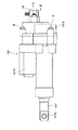
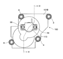
以下、本発明の実施の形態を図面に基づいて説明する。図1は、本実施の形態にかかるアクチュエータを用いる船外機の概略図である。図2は、第1の実施の形態のアクチュエータの正面図である。図3は、図2のアクチュエータを矢印III方向に見た図である。図4は、図3の構成をIV-IV線で切断して矢印方向に見た図である。 Hereinafter, embodiments of the present invention will be described with reference to the drawings. FIG. 1 is a schematic view of an outboard motor using the actuator according to the present embodiment. FIG. 2 is a front view of the actuator according to the first embodiment. FIG. 3 is a view of the actuator of FIG. 2 as viewed in the direction of arrow III. FIG. 4 is a view of the configuration of FIG. 3 taken along line IV-IV and viewed in the direction of the arrow.
図1において、船外機2は、船体1に固定されるケーシング2aと、その上部に取り付けられたカウリング2bとを有している。カウリング2bの内部には、出力軸3をケーシング2aに延在させてなるエンジン(不図示)が搭載されている。出力軸3の下端には、傘歯車3aが取り付けられている。
In FIG. 1, the outboard motor 2 has a
ケーシング2aの下部には、プロペラ軸4が水平に配置され、回転可能に支持されている。プロペラ軸4の図で右端側は、ケーシング2aから外部へ突出しており、その端部にプロペラ5が取り付けられている。
A propeller shaft 4 is horizontally disposed below the
プロペラ軸4は、傘歯車3aに噛合する前進用傘歯車6と後進用傘歯車7とを貫通しており、また傘歯車6,7の間にドグクラッチ8を配置している。プロペラ軸4に対して、ドグクラッチ8は軸線方向に相対移動可能であるが一体的に回転するようになっており、また傘歯車6,7は相対回転可能となっている。図示していないが、ドグクラッチ8は、軸線方向両方向に向いた突起を有しており、図で左方に移動することで突起が傘歯車6の凹部と係合し、ドグクラッチ8と傘歯車6とが一体で回転する。一方、図で右方に移動することで突起が傘歯車7の凹部と係合し、ドグクラッチ8と傘歯車7とが一体で回転する。
The propeller shaft 4 passes through a forward bevel gear 6 and a reverse bevel gear 7 that mesh with the
ドグクラッチ8は、カム軸9により軸線方向に駆動されるようになっている。カム軸9は、操作軸10の回転に応じて軸線方向に変位するように連結されている。操作軸10は、リンク部材11を介して、後述するアクチュエータ100の駆動軸117に連結されている。
The dog clutch 8 is driven in the axial direction by a
図4において、円筒状のハウジング101は、アルミ製のハウジング本体101Aと、その端面に対してボルトB(図3)により組み付けられたアルミ又は樹脂製のカバー部材101Bと、モータブラケット101Cとからなる。ハウジング本体101Aの内部には、モータ室101aとねじ軸室101bとを有する。モータ室101a内には、モータ102が配置されている。モータ102は、板状のモータブラケット101Cに固定されており、モータブラケット101Cは、後述する玉軸受114の外輪をハウジング本体101Aとの間に挟み込み、且つハウジング本体101Aのモータ室101aとねじ軸室101bをふさぐようにして取り付けられている。
In FIG. 4, a
電動のモータ102の回転軸102aは、モータブラケット101Cから突出しており、その端部には金属製の第1ギヤ103が圧入により相対回転不能に取り付けられている。モータブラケット101Cに植設された長軸104の周囲には、樹脂製の第2ギヤ105が回転自在に配置され、これは第1ギヤ103及び第3ギヤ106の大ギヤ部106aに噛合している。
A
樹脂製の第3ギヤ106は、大ギヤ部106aと小ギヤ部106bとを同軸に形成しており、更にねじ軸107の端部に、セレーション結合で相対回転不能に取り付けられている。第3ギヤ106の一部を覆うようにして、支持部材108がモータブラケット101Cに取り付けられている。ここで、第1ギヤ103,第2ギヤ105,第3ギヤ106が第1動力伝達機構を構成する。
The resin-made
第2ギヤ105に隣接して配置された第4ギヤ109が、長軸104の周囲に回転自在に支持されている。樹脂製の第4ギヤ109は、第3ギヤ106の小ギヤ部106bに噛合した大ギヤ部109aと、小ギヤ部109bとを同軸に形成している。
A
第4ギヤ109の小ギヤ部109bは、長軸104に平行して支持部材108に植設された短軸110に対して回転自在に支持された第5ギヤ111の大ギヤ部111aに噛合している。樹脂製の第5ギヤ111は、大ギヤ部111aと小ギヤ部111bとを同軸に形成している。小ギヤ部111bは、第5ギヤ111に隣接して配置され長軸104の周囲に回転自在に支持された第6ギヤ112に噛合している。尚、長軸104及び短軸110と各ギヤとの間には、回転を円滑に行うためのブッシュが配置されていても良い。
The
センサとしてのポテンシオメータ113は、カバー部材101Bの孔101dに嵌合配置され小ねじSB(図2)で固定されており、その測定軸113aは第6ギヤ112に連結され、一体的に回転するようになっている。片持ち状に延在している長軸104の先端は、第6ギヤ112と測定軸113aとを介して、ポテンシオメータ113によって支持され、又は孔101dに支持される。ポテンシオメータ113は、測定軸113aの所定範囲(例えば90度)の角度を精度良く検出できるものである。ここで、第1ギヤ103,第2ギヤ105,第3ギヤ106、第4ギヤ109,第5ギヤ111,第6ギヤ112が第2動力伝達機構を構成する。カバー部材101Bは、各ギヤに異物が侵入しないように密閉するギヤカバーとしての機能を有する。尚、噛合するギヤの樹脂素材を互いに異なるものにすると、摩滅を抑制できるので好ましい。
The
図4において、ねじ軸107は、ハウジング本体101Aに対して、図で右端側を玉軸受114により回転自在に支持されている。ねじ軸107は、左端側に雄ねじ溝107aを形成している。
In FIG. 4, the
ねじ軸107は、円筒状のナット115を貫通している。ナット115の内周面には、雄ねじ溝107aに対向して、雌ねじ溝115aが形成され、両ねじ溝107a、115aによって形成される螺旋状の空間(転走路)には、多数のボール116が転動自在に配置されている。ナット115は、ハウジング本体101Aに対して回り止め(不図示)が設けられ、ねじ軸室101b内において、軸線方向に相対移動可能だが、相対回転不能となっている。尚、軸線方向移動要素であるナット115と、回転要素であるねじ軸107と、転動体であるボール116とでボールねじ機構を構成し、このボールねじ機構と、以下の駆動軸117とで駆動機構を構成する。
The
ねじ軸107の左端は、丸軸状の駆動軸117に形成された袋孔117a内に侵入している。駆動軸117の図で右端は、ナット115に対して同軸に嵌合し、後述するようにコッタ(後述)で連結されて一体的に移動するようになっている。ハウジング本体101Aに対して、駆動軸117はブッシュ118により軸線方向に移動可能に支持されており、且つブッシュ118の左方(外部側)にはシール119が配置され、ハウジング本体101Aと駆動軸117との間から海水や塵埃等の異物が侵入することを防止している。尚、ハウジング本体101Aから突出した駆動軸117の端部には、リンク部材11に連結するための孔117bが形成されている。
The left end of the
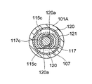
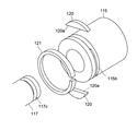
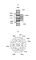
図5は、図4の構成をV-V線で切断して矢印方向に見た図である。図6は、ナット115と駆動軸117とを分解して示す図である。図6において、ナット115の外周には、周溝115bが形成されており、周溝115bの底面は、軸線を挟む平行な二面で削ぎ落とされたような形状であり、これにより周溝115bとナット115の内周面とを連通する貫通溝115c、115c(図5参照)が形成されている。一方、駆動軸117の端部近傍には、掛かり溝としての周溝117cが形成されている。尚、ナット115の内周面と、駆動軸117の外周面とはインロー嵌めとなる寸法を有する。
FIG. 5 is a view of the configuration of FIG. 4 taken along the line VV and viewed in the direction of the arrow. FIG. 6 is an exploded view of the
組み付け時には、駆動軸117の端部をナット115内に挿入し、貫通溝115c、115cが周溝117cの半径方向外方に位置した状態で、半月板状のコッタ120、120を、周溝115bの上方及び下方より挿入する。すると、コッタ120,120は、その平面部120a、120aが貫通溝115c、115cを通って、ナット115の内周面から突出し、駆動軸117の周溝117cに係合することとなる(図5参照)。かかる状態で、ナット115と駆動軸117とは、インロー嵌めにより軸芯を合わせた状態でガタなく軸線方向に連結され、一体的に移動することとなる。
At the time of assembly, the end of the
その後、リングの一部を切り欠いてなる(即ちC字状)の抑え部材121を、弾性変形させながらナット115の周溝115bに嵌め込む。これによりコッタ120,120は、貫通溝115c、115c内に配置された状態で抑え部材121の内周に抑えられて固定され、コッタ120,120が周溝115bから抜け出ることが阻止される。抑え部材121を、摺動性に優れた樹脂から形成し、ナット115の周溝115bに嵌め込まれた状態で、ナット115の外径より若干大きい外径を有するようにすれば、ナット115の移動時にハウジング101Aの内周に対して摺動するようになるので、金属同士の接触を回避し摩耗や引きずりトルクの低減を行える。
Thereafter, the holding
図1において、モータ102の配線102bと、ポテンシオメータ113の配線113bは、カウリング2b側に延在し、更に不図示の駆動回路に接続されている。
In FIG. 1, the
図9は、本実施の形態の変形例にかかるナット115と駆動軸117とを連結した状態で側方から見た図である。図10は、図9の構成の矢印Xで示す部位を拡大して示す図である。本変形例においては、ナット115の周溝115bに嵌め込んだ抑え部材121に、内外周を貫通する孔121aを形成している。
FIG. 9 is a view seen from the side in a state in which the
本変形例によれば、抑え部材121を周溝115bに組み付ける前に、その内部にコッタ120が正しく組み付けられていれば、孔121aを通して作業者がコッタ120を視認できるので、その欠品や誤組を回避できる。孔121aは、各コッタ120に対して1つずつ設けられていると好ましいが、単一の孔121aのみを形成した場合でも、抑え部材121をナット115に対して相対回転させることで、2つのコッタ120、120の組付確認を行うこともできる。孔120の形状は、円形に限らず矩形、スリット状であっても良いし、孔の代わりに抑え部材の側面で内外周を連結する切欠を設けても良い。
According to this modified example, if the
次に、本実施の形態の動作について説明する。ここで、傘歯車3aが前進用傘歯車6と後進用傘歯車7のいずれにも常時噛合しているから、内燃機関が動作している限り、傘歯車3aから動力を伝達された傘歯車6,7は互いに逆方向に回転している。しかしながら、ニュートラルの状態においては、図1に示すように、ドグクラッチ8がいずれの傘歯車6,7と係合していないので、出力軸3の動力は、プロペラ軸4に伝達されずプロペラ5は回転しないこととなる。
Next, the operation of the present embodiment will be described. Here, since the
ここで、ニュートラルの状態から、操作者が不図示のレバーを前進方向に操作したものとする。すると、図4において、モータ102に所定の極性の電力が供給され、回転軸102aが所定の方向に回転する。回転軸102aの回転力は、第1ギヤ103,第2ギヤ105,第3ギヤ106を介してねじ軸107に伝達されるので、ねじ軸107の回転に応じてナット115が図4で左方へと変位する。ナット115が左方に変位すると、駆動軸117が突出する方向に移動するので、図1においてリンク部材11が枢動する。従って操作軸10が所定の方向に回転し、不図示のカム機構を介してカム軸9が左方に移動し、ドグクラッチ8を前進用傘歯車6と係合させる。これにより出力軸3の動力を、傘歯車3a、6及びドグクラッチ8を介してプロペラ軸4に伝達し、プロペラ5を正回転させることができる。
Here, it is assumed that the operator operates a lever (not shown) in the forward direction from the neutral state. Then, in FIG. 4, electric power having a predetermined polarity is supplied to the
一方、回転軸102aの回転力は、第1ギヤ103,第2ギヤ105,第3ギヤ106、第4ギヤ109,第5ギヤ111,第6ギヤ112を介してポテンシオメータ113の測定軸113aに伝達される。測定軸113aの回転に応じた信号は、ポテンシオメータ113から配線113bを介して不図示の駆動回路に入力される。かかる信号に基づいてねじ軸107が所定の回転量だけ回転したと判断すれば、駆動回路はモータ102への電力供給を停止させる。
On the other hand, the rotational force of the
これに対し、操作者が不図示のレバーを後進方向に操作したときは、図4において、モータ102に逆極性の電力が供給され、回転軸102aが逆方向に回転するので、上述とは逆の動作で、アクチュエータ100の駆動軸117が引き込む方向に移動する。従って、図1においてリンク部材11を介して操作軸10が逆方向に回転し、不図示のカム機構を介してカム軸9が右方に移動し、ドグクラッチ8を後進用傘歯車7と係合させる。これにより出力軸3の動力を、傘歯車3a、7及びドグクラッチ8を介してプロペラ軸4に伝達し、プロペラ5を逆回転させることができる。
On the other hand, when the operator operates a lever (not shown) in the reverse direction, in FIG. 4, power having a reverse polarity is supplied to the
本実施の形態によれば、駆動軸117は、コッタ120,120によりナット115と連結されているので、周方向の位相の合わせが自由となり、アクチュエータ内部に設置されることの多いナット115の回転止めと、駆動軸117に成形される他部材との結合面との周方向の位相を自由に設定できるので、格段に組付性が向上する。更に、コッタ120,120がナット115の周溝115bから抜け出ることを阻止する抑え部材121が、ナット115の外径より僅かに飛び出して入る為、抑え部材121とハウジング101Aの内周面とが接触し、ナット115の軸芯とがハウジング101Aの内周面中心とが精度良く合致する。しかも、抑え部材121に、高摺動特性を持つ合成樹脂等の材料を使用すれば、ナット115の外周面及びハウジング101Aの内周面の摩耗が抑制され、安定した作動が得られる。
According to the present embodiment, since the
図7は、別な実施の形態にかかるアクチュエータの軸受周辺を示す断面図である。図8は、コッタの斜視図である。本実施の形態においては、ねじ軸107は、第1フランジ部107bと、第2フランジ部107cとを有する。第1フランジ部107bと第2フランジ部107cとの間には、大径部107dと、小径部107eとが形成されている。軸受114の内輪は、大径部107dに圧入により嵌合し、且つ第1フランジ部107bに端面を当接させている。
FIG. 7 is a cross-sectional view showing the periphery of a bearing of an actuator according to another embodiment. FIG. 8 is a perspective view of the cotter. In the present embodiment, the
コッタ220,220は、図8で示すように、ドーナツ板状を半割したような形状であり、小径部107eの半径方向外方から対向して挿入され、その内縁を小径部107eの外周に係合させている。コッタ220,220を小径部107eの外周に係合させた状態で、コッタ220、220は軸受114の内輪と第2フランジ部107cとの間に挟持される。これにより、軸受114の内輪の抜け止めを図ることができる。
As shown in FIG. 8, the
但し、そのままではコッタ220,220が脱落する恐れがあるので、ねじ軸107に固定された樹脂製(金属製でも良い)の第3ギヤ106に形成した中空円筒部106cを、第2フランジ部107c側から延在させ、コッタ220,220の外周を覆うようにする。これにより、コッタ220,220は小径部107eから離隔する方向に移動できなくなり、即ち抜け止めを図ることができる。本実施の形態によれば、サークリップ等が不要となり、簡素で部品点数が少なく組付性に優れるアクチュエータが提供される。それ以外の構成は、上述した実施の形態と同様であるため説明を省略する。尚、コッタ220,220を内包する動力伝達部材としては、ギヤに限らずカップリング部材でも良い。
However, since the
図11は、更に別な実施の形態にかかるアクチュエータの軸受周辺を示す断面図である。図12(a)は、コッタの側面図であり、図12(b)は、図12(a)の1つのコッタを矢印XIIB方向に見た図である。本実施の形態においては、動力伝達部材であるギヤ306が、ねじ軸107の端部にセレーション結合され且つ外周に小ギヤを形成してなる中央部306aと、中央部306aから半径方向に延在するフランジ部306bと、フランジ部306bの外周に形成された環状のギヤ部306cと、フランジ部306bから軸線方向に延在し、ギヤ部306cの軸線方向端部より外方(左方)に突出してなる中空円筒部306dとを有する。
FIG. 11 is a cross-sectional view showing the periphery of a bearing of an actuator according to still another embodiment. 12A is a side view of the cotter, and FIG. 12B is a view of one cotter of FIG. 12A as viewed in the direction of the arrow XIIB. In the present embodiment, a
コッタ320は、図12に示すように、ねじ軸107の小径部107eに係合する半円状の切欠320aを有する扇状のフランジ部320bと、フランジ部320bの外縁から軸線方向に延在する半円筒部320cとからなる。尚、コッタ320は、HRC15以上の硬さを有すると好ましい。
As shown in FIG. 12, the
図11に示すように、一対のコッタ320,320を対向してねじ軸107に組み付けた状態で、ギヤ306を右方からねじ軸107に組み付けると、モータブラケット101Cとギヤ306のギヤ部306cとの間には隙間CLが生じる。また、ギヤ306の中空円筒部306dが、モータブラケット101Cの近傍まで延在し、コッタ320の半円筒部320cの端部側のみを包囲する。尚、それ以外の構成については、上述した実施の形態と同様であるため説明を省略する。
As shown in FIG. 11, when the
組み付けた状態で、矢印Yに示す方向から作業者が隙間CLを覗き込むと、コッタ320が定位置に組み付けられている場合、中空円筒部306dとモータブラケット101Cとの間に、コッタ320の一部が視認されることとなる。一方、欠品等によりコッタ320が組み付けられていない場合、作業者が隙間CLを覗き込んだとき、コッタ320の代わりにねじ軸107が視認されることとなる。これにより、コッタ320が定位置に組み付けられているか否かの検査を、ギヤ306を分解することなく行うことができる。
When the operator looks into the gap CL from the direction indicated by the arrow Y in the assembled state, when the
図13は、更に別な実施の形態にかかるアクチュエータの軸受周辺を示す断面図である。図14(a)は、ギヤの側面図であり、図14(b)は、図14(a)のギヤを矢印XIVB方向に見た図である。図11に示す実施の形態に対し、本実施の形態においては、ギヤ306’の中空円筒部306dを延長し、更に周方向に等間隔に切欠306eを形成している。本体306aの外周に形成された小ギヤ部306fは、第4ギヤ109の大ギヤ部109a(図4)に噛合する。尚、それ以外の構成については、上述した実施の形態と同様であるため説明を省略する。
FIG. 13 is a cross-sectional view showing the periphery of a bearing of an actuator according to still another embodiment. 14 (a) is a side view of the gear, and FIG. 14 (b) is a view of the gear of FIG. 14 (a) as viewed in the direction of the arrow XIVB. In contrast to the embodiment shown in FIG. 11, in this embodiment, the hollow
図13に示すように、一対のコッタ320,320を対向してねじ軸107に組み付けた状態で、ギヤ306を右方からねじ軸107に組み付けると、ギヤ306’の中空円筒部306dが、モータブラケット101Cの中央孔内に進入し、コッタ320の半円筒部320cを軸線方向にわたって包囲するが、コッタ320は切欠306eを介して半径方向に露出することとなる。
As shown in FIG. 13, when the
組み付けた状態で、矢印Yに示す方向から作業者が隙間CLを覗き込むと、コッタ320が定位置に組み付けられている場合、中空円筒部306dの切欠306eを通して、コッタ320の一部が視認されることとなる。一方、欠品等によりコッタ320が組み付けられていない場合、作業者が隙間CLを覗き込んだとき、コッタ320の代わりにねじ軸107が視認されることとなる。これにより、コッタ320が定位置に組み付けられているか否かの検査を、ギヤ306’を分解することなく行うことができる。尚、切欠の代わりに孔を設けても良い。
When the operator looks into the gap CL from the direction indicated by the arrow Y in the assembled state, when the
図15は、更に別な実施の形態にかかるアクチュエータの軸受周辺を示す断面図である。図16(a)は、コッタの側面図であり、図16(b)は、図16(a)の1つのコッタを矢印XVIB方向に見た図である。図11、12に示す実施の形態に対し、本実施の形態においては、コッタの構成を変更している。 FIG. 15 is a cross-sectional view showing the periphery of a bearing of an actuator according to still another embodiment. 16A is a side view of the cotter, and FIG. 16B is a view of one cotter of FIG. 16A viewed in the direction of the arrow XVIB. Compared to the embodiment shown in FIGS. 11 and 12, in this embodiment, the configuration of the cotter is changed.
より具体的には、コッタ320’は、図16に示すように、ねじ軸107に係合する半円状の切欠320aを有する扇状のフランジ部320bと、フランジ部320bから軸線方向に延在する半円筒部320cと、半円筒部320cの側面に形成された溝状の凹部320dとからなる。尚、それ以外の構成については、図11,12に示す実施の形態と同様であるため説明を省略する。
More specifically, the
図15に示すように、一対のコッタ320’,320’を対向してねじ軸107に組み付けた状態で、ギヤ306を右方からねじ軸107に組み付けると、ギヤ306の中空円筒部(ここでは凸部)306dが、コッタ320’の半円筒部320cを包囲することなく、その側面に形成された凹部320dに係合する。
As shown in FIG. 15, when the
組み付けた状態で、矢印Yに示す方向から作業者が隙間CLを覗き込むと、コッタ320’が定位置に組み付けられている場合、コッタ320’の外周の一部が視認されることとなる。一方、欠品等によりコッタ320’が組み付けられていない場合、作業者が隙間CLを覗き込んだとき、コッタ320’の代わりにギヤ306の中空円筒部306dが視認されることとなる。これにより、コッタ320’が定位置に組み付けられているか否かの検査を、ギヤ306を分解することなく行うことができる。尚、コッタ320’と,ねじ軸107又は中空円筒部306dの色を変えることで、視認性を高めることができる。
When the operator looks into the gap CL from the direction indicated by the arrow Y in the assembled state, when the cotter 320 'is assembled in a fixed position, a part of the outer periphery of the cotter 320' is visually recognized. On the other hand, when the cotter 320 'is not assembled due to a missing item or the like, when the operator looks into the gap CL, the hollow
以上、本発明を実施の形態を参照して説明してきたが、本発明は上記実施の形態に限定して解釈されるべきではなく、適宜変更・改良が可能であることはもちろんである。本発明にかかるアクチュエータは、船舶用に限らず、車両用、一般産業機械用にも用いることができる。 The present invention has been described above with reference to the embodiments. However, the present invention should not be construed as being limited to the above-described embodiments, and can be modified or improved as appropriate. The actuator according to the present invention can be used not only for ships but also for vehicles and general industrial machines.
1 船体
2 船外機
2a ケーシング
2b カウリング
3 出力軸
3a 傘歯車
4 プロペラ軸
5 プロペラ
6 前進用傘歯車
7 後進用傘歯車
8 ドグクラッチ
9 カム軸
10 操作軸
11 リンク部材
12 ブリーザパイプ
17 駆動軸
100 アクチュエータ
101 ハウジング
101A ハウジング本体
101B カバー部材
101C モータブラケット
101a モータ室
101b ねじ軸室
101d 孔
102 モータ
102a 回転軸
102b 配線
103 第1ギヤ
104 長軸
105 第2ギヤ
106 第3ギヤ
106a 大ギヤ部
106b 小ギヤ部
107 ねじ軸
107a 雄ねじ溝
108 支持部材
109 第4ギヤ
109a 大ギヤ部
109b 小ギヤ部
110 短軸
111 第5ギヤ
111a 大ギヤ部
111b 小ギヤ部
112 第6ギヤ
113 ポテンシオメータ
113a 測定軸
113b 配線
114 玉軸受
115 ナット
115a 雌ねじ溝
116 ボール
117 駆動軸
117a 袋孔
118 ブッシュ
119 シール
120,220 コッタ
121 抑え部材
121a 孔
306、306’ ギヤ
306a 中央部
306b フランジ部
306c ギヤ部
306c フランジ部
306d 中空円筒部
306e 切欠
320、320’ コッタ
320a 切欠
320b フランジ部
320c 半円筒部
320d 凹部
CL 隙間
Y 矢印
B ボルト
DESCRIPTION OF SYMBOLS 1 Hull 2
Claims (4)
ハウジングと、
前記ハウジングに取り付けられ、回転軸を有する電動モータと、
前記回転軸に連結されて回転する回転要素と、
前記被駆動部材に連結され、前記回転要素の回転に応じて軸線方向に移動する軸線方向移動要素と、を有し、
前記軸線方向移動要素は、前記被駆動部材を内包しており、且つ内外周を連通する貫通溝を形成しており、
前記貫通溝内に挿入されたコッタが、前記被駆動部材に係合し、
前記被駆動部材は、前記コッタが係合する全周に設けられた掛かり溝を有することを特徴とするアクチュエータ。 In an actuator that drives a driven member,
A housing;
An electric motor attached to the housing and having a rotating shaft;
A rotating element connected to the rotating shaft and rotating;
An axial movement element coupled to the driven member and moving in the axial direction in accordance with the rotation of the rotation element;
The axial direction moving element includes the driven member, and forms a through groove that communicates the inner and outer peripheries ,
Cotter said inserted within the through groove, engage the the driven member,
The driven member, the actuator which the cotter is characterized Rukoto which have a consuming groove provided on the entire periphery to be engaged.
前記抑え部材は、内外周を貫通する孔又は切欠を有していることを特徴とする請求項2に記載のアクチュエータ。 An annular restraining member is attached to the axial movement element so as to enclose the cotter inserted in the through groove,
The actuator according to claim 2, wherein the holding member has a hole or a notch penetrating the inner and outer peripheries.
Priority Applications (1)
| Application Number | Priority Date | Filing Date | Title |
|---|---|---|---|
| JP2008069421A JP5263652B2 (en) | 2007-05-17 | 2008-03-18 | Actuator |
Applications Claiming Priority (5)
| Application Number | Priority Date | Filing Date | Title |
|---|---|---|---|
| JP2007131818 | 2007-05-17 | ||
| JP2007131818 | 2007-05-17 | ||
| JP2007245147 | 2007-09-21 | ||
| JP2007245147 | 2007-09-21 | ||
| JP2008069421A JP5263652B2 (en) | 2007-05-17 | 2008-03-18 | Actuator |
Related Child Applications (1)
| Application Number | Title | Priority Date | Filing Date |
|---|---|---|---|
| JP2012243382A Division JP5545603B2 (en) | 2007-05-17 | 2012-11-05 | Actuator |
Publications (3)
| Publication Number | Publication Date |
|---|---|
| JP2009095221A JP2009095221A (en) | 2009-04-30 |
| JP2009095221A5 JP2009095221A5 (en) | 2011-05-12 |
| JP5263652B2 true JP5263652B2 (en) | 2013-08-14 |
Family
ID=40666625
Family Applications (2)
| Application Number | Title | Priority Date | Filing Date |
|---|---|---|---|
| JP2008069421A Active JP5263652B2 (en) | 2007-05-17 | 2008-03-18 | Actuator |
| JP2012243382A Active JP5545603B2 (en) | 2007-05-17 | 2012-11-05 | Actuator |
Family Applications After (1)
| Application Number | Title | Priority Date | Filing Date |
|---|---|---|---|
| JP2012243382A Active JP5545603B2 (en) | 2007-05-17 | 2012-11-05 | Actuator |
Country Status (1)
| Country | Link |
|---|---|
| JP (2) | JP5263652B2 (en) |
Families Citing this family (8)
| Publication number | Priority date | Publication date | Assignee | Title |
|---|---|---|---|---|
| JP5807424B2 (en) * | 2010-07-23 | 2015-11-10 | 日本精工株式会社 | Actuator |
| JP5866852B2 (en) * | 2010-08-18 | 2016-02-24 | 日本精工株式会社 | Actuator |
| JP5853616B2 (en) * | 2010-11-29 | 2016-02-09 | 日本精工株式会社 | Actuator and manufacturing method thereof |
| JP5982291B2 (en) * | 2013-01-29 | 2016-08-31 | 日本精工株式会社 | Toroidal continuously variable transmission |
| CN106949216B (en) * | 2016-01-06 | 2023-08-01 | 深圳市兆威机电股份有限公司 | Transmission mechanism |
| CN110418910A (en) * | 2017-03-21 | 2019-11-05 | 美蓓亚三美株式会社 | Linear actuator element |
| EP3901490B1 (en) * | 2020-04-20 | 2023-03-01 | elero GmbH | Linear drive |
| JP7375992B1 (en) | 2023-07-20 | 2023-11-08 | 日本精工株式会社 | Rotary linear motion converter and shift actuator |
Family Cites Families (13)
| Publication number | Priority date | Publication date | Assignee | Title |
|---|---|---|---|---|
| JPS62114248U (en) * | 1986-01-11 | 1987-07-21 | ||
| JP2593328B2 (en) * | 1988-03-02 | 1997-03-26 | 本田技研工業株式会社 | ball bearing |
| JPH087164Y2 (en) * | 1990-12-11 | 1996-03-04 | 三輪精機株式会社 | Power shift device for transmission operation |
| JP2000145914A (en) * | 1998-11-17 | 2000-05-26 | Tsubakimoto Chain Co | Bearing linear actuator with backstop mechanism |
| JP2000161461A (en) * | 1998-11-30 | 2000-06-16 | Nsk Ltd | Ball screw type linear actuator |
| JP4711465B2 (en) * | 1999-09-05 | 2011-06-29 | 本田技研工業株式会社 | Swash plate drive device for swash plate type hydrostatic continuously variable transmission |
| JP2001200911A (en) * | 1999-11-11 | 2001-07-27 | Honda Motor Co Ltd | Axial direction positioning structure of member to be fixed |
| JP2003113917A (en) * | 2001-10-04 | 2003-04-18 | Dyadic Systems Co Ltd | Motor-driven cylinder |
| JP2004100931A (en) * | 2002-09-13 | 2004-04-02 | Asmo Co Ltd | Linear actuator |
| JP4273779B2 (en) * | 2003-01-31 | 2009-06-03 | いすゞ自動車株式会社 | Punch press equipment |
| JP4042820B2 (en) * | 2003-09-10 | 2008-02-06 | 株式会社ツバキエマソン | Electric cylinder |
| JP2005180505A (en) * | 2003-12-17 | 2005-07-07 | Nsk Ltd | Positioning device |
| JP5234249B2 (en) * | 2007-03-22 | 2013-07-10 | 日本精工株式会社 | Actuator |
-
2008
- 2008-03-18 JP JP2008069421A patent/JP5263652B2/en active Active
-
2012
- 2012-11-05 JP JP2012243382A patent/JP5545603B2/en active Active
Also Published As
| Publication number | Publication date |
|---|---|
| JP2013061070A (en) | 2013-04-04 |
| JP5545603B2 (en) | 2014-07-09 |
| JP2009095221A (en) | 2009-04-30 |
Similar Documents
| Publication | Publication Date | Title |
|---|---|---|
| JP5545603B2 (en) | Actuator | |
| JP5283723B2 (en) | Ship propulsion machine | |
| US20140041468A1 (en) | Electric actuator | |
| US4257506A (en) | Shifter linkage for a cone clutch | |
| JP2006029420A (en) | Transmission unit | |
| US9879719B2 (en) | Supporting structure for gear of outboard motor | |
| EP2592307A2 (en) | Electric actuator | |
| JP5234249B2 (en) | Actuator | |
| US10119564B2 (en) | Supporting structure for gear of outboard motor | |
| JP5218817B2 (en) | Actuator | |
| WO2015170593A1 (en) | Gear shift operation mechanism | |
| JPS61175346A (en) | Propulsive machinery of boat | |
| TW200950924A (en) | Tool cartridge gear motor | |
| JP4840092B2 (en) | Shift-by-wire range switching device | |
| US10604223B2 (en) | Reduction reverse gear and ship including the same | |
| JP3110721B2 (en) | Thrust receiving structure of ship propulsion machine | |
| JP2009052448A (en) | Starter with intermediate gear | |
| US10040530B2 (en) | Outboard motor | |
| JP2008195200A (en) | Control device for actuator of ship propeller and ship propeller | |
| JP2826795B2 (en) | Drive transmission for ship propulsion | |
| JP2009197887A (en) | Actuator | |
| JP2008228557A (en) | Actuator | |
| US10293909B1 (en) | Outboard motor | |
| JP3131586B2 (en) | Propeller drive for ship propulsion | |
| JP2008267550A (en) | Actuator |
Legal Events
| Date | Code | Title | Description |
|---|---|---|---|
| A621 | Written request for application examination |
Free format text: JAPANESE INTERMEDIATE CODE: A621 Effective date: 20110315 |
|
| A521 | Written amendment |
Free format text: JAPANESE INTERMEDIATE CODE: A523 Effective date: 20110325 |
|
| A977 | Report on retrieval |
Free format text: JAPANESE INTERMEDIATE CODE: A971007 Effective date: 20120817 |
|
| A131 | Notification of reasons for refusal |
Free format text: JAPANESE INTERMEDIATE CODE: A131 Effective date: 20120907 |
|
| A521 | Written amendment |
Free format text: JAPANESE INTERMEDIATE CODE: A523 Effective date: 20121105 |
|
| TRDD | Decision of grant or rejection written | ||
| A01 | Written decision to grant a patent or to grant a registration (utility model) |
Free format text: JAPANESE INTERMEDIATE CODE: A01 Effective date: 20130405 |
|
| A61 | First payment of annual fees (during grant procedure) |
Free format text: JAPANESE INTERMEDIATE CODE: A61 Effective date: 20130418 |
|
| R150 | Certificate of patent or registration of utility model |
Free format text: JAPANESE INTERMEDIATE CODE: R150 Ref document number: 5263652 Country of ref document: JP Free format text: JAPANESE INTERMEDIATE CODE: R150 |