JP5262575B2 - Operation management system - Google Patents
Operation management system Download PDFInfo
- Publication number
- JP5262575B2 JP5262575B2 JP2008275015A JP2008275015A JP5262575B2 JP 5262575 B2 JP5262575 B2 JP 5262575B2 JP 2008275015 A JP2008275015 A JP 2008275015A JP 2008275015 A JP2008275015 A JP 2008275015A JP 5262575 B2 JP5262575 B2 JP 5262575B2
- Authority
- JP
- Japan
- Prior art keywords
- data
- information
- vehicle
- transport
- towing
- Prior art date
- Legal status (The legal status is an assumption and is not a legal conclusion. Google has not performed a legal analysis and makes no representation as to the accuracy of the status listed.)
- Active
Links
Images


Landscapes
- Time Recorders, Dirve Recorders, Access Control (AREA)
Abstract
Description
本発明は、牽引部分と荷物積載部分とが分離できる分離型輸送車両を用いて、鉄鋼製品などの素材や製品の輸送運行管理を行う運行管理システムに関するものである。 The present invention relates to an operation management system that performs transportation operation management of materials and products such as steel products using a separation-type transport vehicle that can separate a tow portion and a load carrying portion.
製鉄所内における鉄鋼素材・製品の輸送は、牽引部分と荷物積載部分が分離できる分離型輸送車両を使用して行っている。これらの分離型輸送車両の実績管理は、各車両に取り付けた車載端末で入力された実績をもとに行われ、管理されている。 Steel materials and products are transported in steelworks using a separate transport vehicle that can separate the tow portion and the load carrying portion. The performance management of these separation-type transport vehicles is performed and managed based on the results input from the in-vehicle terminal attached to each vehicle.
これまでの運搬車両の運行管理技術としては、例えば、特許文献1や特許文献2などの技術が開示されている。
For example,
特許文献1に開示された技術は、車両運転手による端末への実績入力忘れなどに対応するためにデータを補完する技術である。また、特許文献2に開示された技術は、車両の効率的な稼動状況をモニタするために、車両に車速センサや荷重センサをつけて車両の状態を検出して詳細なデータを管理しようとするものである。
しかしながら、本発明が対象としている分離型輸送車両の場合、車両がどの位置からどの位置へ、どのような状態であるか(例えば、荷物を積載している状態か、荷物を載せる台車だけを積載している状態か、何も積載していない状態か、など)を把握する必要がある。特に、車両の輸送能率をあげる上では、上記台車の状態把握は、非常に重要である。 However, in the case of the separation-type transport vehicle targeted by the present invention, from what position to which position the vehicle is in what state (for example, a state in which a load is loaded or only a carriage on which a load is loaded) It is necessary to know whether it is in a state of being loaded or not loaded. In particular, in order to increase the transportation efficiency of the vehicle, it is very important to grasp the state of the carriage.
上述した特許文献1や特許文献2に開示された技術は、分離型輸送車両ではない車両への適用技術であるために、そのままでは、分離型車両に適用は困難であった。例えば、分離型輸送車両の輸送能率を向上させたい時に、無駄な車両の動きや待機している時間が分からず、効果的な対策が打てなかった。
Since the techniques disclosed in
また、どこからどこへ動かすといった輸送ダイヤグラムを作成したとしても、分離型輸送車両の場合には、上述したどのような状態であるかを把握していなければ、輸送能率向上のための効果的な対策が打てない。 In addition, even if a transportation diagram of where to move is created, in the case of a separation-type transportation vehicle, if it is not understood what the above-mentioned state is, effective measures for improving transportation efficiency I can't hit.
さらに、特許文献2のような各種センサを利用しようとすると、牽引車両と運搬台車の両方に取り付ける必要があり、車両が多数台ある製鉄所のような場合には、コストが膨大になるという問題もある。
Furthermore, if it is going to utilize various sensors like
本発明は、上記課題を解決するためになされたものであり、牽引部分と荷物積載部分とが分離できる分離型輸送車両を用いて、鉄鋼製品などの素材や製品の効率的な輸送運行管理を行う運行管理システムを提供することを目的とする。 The present invention has been made in order to solve the above-described problems. By using a separation-type transportation vehicle that can separate a tow portion and a load carrying portion, efficient transportation operation management of materials and products such as steel products can be performed. The purpose is to provide an operation management system.
本発明の請求項1に係る発明は、牽引車両と運搬台車とが分離可能な分離型車両の運行管理を行う運行管理システムであって、運搬台車を牽引して輸送した際に、その輸送開始時刻・位置の情報、終了時刻・位置の情報、運搬台車に荷物を積載したか否かの情報と、を記憶する記憶装置と、前記記憶装置から運搬台車を牽引して輸送した際の情報を入力し、該入力した情報から運搬台車を牽引しないで移動した場合の終了時刻・位置と開始時刻・位置とを算出する演算装置と、前記記憶装置に記憶された情報と前記演算装置で算出された情報を用いて、運搬台車を牽引した荷物を積載して輸送した場合と、運搬台車を牽引したが荷物を積載せず輸送した場合と、運搬台車を牽引しないで移動した場合とを、それぞれ弁別可能な形態で、同一のダイヤグラムに表示する表示装置とを備えることを特徴とする運行管理システムである。
The invention according to
本発明は、運搬台車を牽引しないで移動した場合の終了時刻・位置と開始時刻・位置とを算出し、運搬台車を牽引した荷物を積載して輸送した場合と、運搬台車を牽引したが荷物を積載せず輸送した場合と、運搬台車を牽引しないで移動した場合とを、それぞれ弁別可能な形態で、同一のダイヤグラムに表示するようにしたので、分離型輸送車両の輸送実態の把握が容易になり、なぜ台車のみ積載して輸送したのか、なぜ何も積載しないで移動したかの原因を探り、対策が打つことで、輸送能率の向上が可能となった。 The present invention calculates the end time / position and start time / position when moving without towing the transport cart, and loads and transports the load that pulls the transport cart, and pulls the transport cart but does not load the load. It is now possible to distinguish between the case where the vehicle is transported without loading and the case where the vehicle is moved without towing the carriage in the same diagram. As a result, it was possible to improve the transportation efficiency by investigating the reasons why the trucks were loaded and transported only, and why they moved without loading anything.
図1は、本発明が適応される全体システムの構成例を示す図である。図中、1は運行管理システム、2は上位計算機、3は配車計画システム、4は記憶装置、5は製造管理システム、6は車両端末、11は演算装置、および12は表示装置をそれぞれ表す。 FIG. 1 is a diagram showing a configuration example of an entire system to which the present invention is applied. In the figure, 1 is an operation management system, 2 is a host computer, 3 is a dispatch plan system, 4 is a storage device, 5 is a manufacturing management system, 6 is a vehicle terminal, 11 is a computing device, and 12 is a display device.
各工場には、製造管理システム5がそれぞれあり、各工場での製品の製造状況を管理している。上位計算機2は、各工場の製造管理システム5とLANなどの通信回線で接続され、各工場から製造実績データを入力したり、製造完了したコイルを次にどこに、どのように運搬するかといった命令データを各工場の製造管理システム5に出力可能となっており、製鉄所全体の運行実績データを管理できるようになっている。
Each factory has a
また、牽引車両(図示せず)には、上位計算機2と無線によりデータの送受信が可能な車両端末6を有しており、この車両端末6を介して、運転手に牽引車の移動先や牽引する台車番号の情報を指示したり、運転手から台車を運搬した実績データを入力できるようになっている。車両端末6で入力された運行実績データは、上位計算機2にて入力し、上位計算機2で、そのデータを運行実績データとして記憶装置4に保存している。
In addition, the tow vehicle (not shown) has a vehicle terminal 6 that can transmit and receive data to and from the
上位計算機2には、さらに配車計画システム3と運行管理システム1が、通信回線で接続されて、必要な情報が相互に送受信できるようになっている。
The
配車計画システム3は、運搬車両の運行計画を立案するシステムで、立案した計画データは上位計算機2に送信され、各工場単位に編集されて、各工場で製造した製品(現品)の搬出計画情報として、各工場に運行計画の指示情報として送られる。また、牽引車両の運転者にも、牽引車両単位にデータが分割され、運転計画情報として提供される。
The vehicle
運行管理システム1は、運行実績のデータを上位計算機2から入力し、運行が効率的に行われていたかを解析するためのシステムである。運搬台車を牽引して輸送した際に、その輸送開始時刻・位置の情報、終了時刻・位置の情報、運搬台車に荷物を積載したか否かの情報と、を記憶する記憶装置4と、この記憶装置4から運搬台車を牽引して輸送した際の情報を入力し、入力した情報から運搬台車を牽引しないで移動した場合の終了時刻・位置と開始時刻・位置とを算出する演算装置11と、前記記憶装置4に記憶された情報と前記演算装置11で算出された情報を用いて、運搬台車を牽引した荷物を積載して輸送した場合と、運搬台車を牽引したが荷物を積載せず輸送した場合と、運搬台車を牽引しないで移動した場合とを、それぞれ弁別可能な形態で、同一のダイヤグラムに表示する表示装置12とで主に構成される。
The
図2は、配車計画システムの処理フロー例を示す図である。各工場で製品(コイル)が製造完了し、出荷用のコイル置場に置かれて、別の工場や倉庫に移動可能となったタイミングで、工場の製造管理システム5から配車計画システムに該当コイルに関するデータが入力される(ステップS11のYes参照)。そして、そのコイルが、次にどこに行くか、いつ搬出するかなどを決定する(ステップS12)。この決定は、コイルが出荷されるまでに通過すべき製造工程に関するデータ(本配車計画システムとは別の生産計画システムなどで決定されている)に基づいて行われる。
FIG. 2 is a diagram illustrating a processing flow example of the vehicle allocation planning system. At the timing when the products (coils) have been manufactured at each factory, placed in the coil storage area for shipment, and moved to another factory or warehouse, the factory
さらに、そのコイルを運搬するための積載用台車を決定する(ステップS13)。積載台車の決定は、現在積載していない空き台車であるか、あるいは、そのコイルを運搬するまでに空き台車になる候補の台車データを抽出し、さらに該当する工場に台車を運搬するのに、もっとも効率的な台車(例えば、距離が最も近い場所にある台車)を選択する。決定したデータを、台車の情報を工場の製造管理システム5に出力する(ステップS14)。工場の製造管理システム5はそのデータを入力すると、コイルを台車に積載するための工場内のクレーンの運行計画を作成し、その計画により、台車に積載作業を行うことになる。
Further, a loading carriage for carrying the coil is determined (step S13). The determination of the loading cart is to determine whether it is an empty cart that is not currently loaded, or candidate cart data that becomes an empty cart by the time the coil is transported, and to transport the cart to the corresponding factory, The most efficient trolley (for example, the trolley at the closest location) is selected. Information about the determined data is output to the
一方、ステップS13までに決定した台車を牽引するための牽引車両を決定する(ステップS15)。牽引車両の決定も、台車に積載すべきコイルが全て完了するタイミングで、台車を牽引していない予定の牽引車両を抽出し、その中から効率的な牽引車両(例えば、距離が最も近い場所にいる牽引車両)を選択する。そして、その車両に対応する車両端末6に指示データとして出力する(ステップS16)。このような処理によって、配車計画がされ、運行が実行されることになる。 On the other hand, a tow vehicle for towing the cart determined up to step S13 is determined (step S15). The towing vehicle is also determined by extracting the towing vehicle that is not towing the bogie at the timing when all the coils to be loaded on the bogie are completed, and selecting an efficient towing vehicle (for example, at the closest distance). Tow vehicle). And it outputs as instruction data to the vehicle terminal 6 corresponding to the vehicle (step S16). By such processing, a vehicle allocation plan is made and the operation is executed.
運行実績については、牽引車両の運転手が、指示された台車を、指示された場所に移動完了した、あるいは、指示された場所から移動開始をする、というタイミングにおいて、車両端末6に実績データを入力する。 As for the operation results, at the timing when the driver of the tow vehicle completes the movement of the designated cart to the designated location or starts to move from the designated location, the performance data is stored in the vehicle terminal 6. input.
入力するデータ項目には、例えば、以下に挙げるようなものがある。
(1)「牽引車両No.」:牽引車両を識別するための番号
(2)「台車No.」:搬送台車を識別するための番号
(3)「重量」:搬送台車に積載された現品の重量
(4)「個数」:台車に積載された現品の個数
(5)「出発/到着」:搬送台車を牽引して当該工場から出発した、当該工場に台車を搬入して到着したかの情報
(6)「出発時刻/到着時刻」:搬送台車が当該工場から搬出または当該工場から搬入された時刻
これらのデータは、上位計算機2に送信されて、記憶装置4に運行実績データとして記憶される。
Examples of data items to be input include the following.
(1) “Towing Vehicle No.”: Number for identifying the towing vehicle (2) “Dolly No.”: Number for identifying the transport cart (3) “Weight”: The actual product loaded on the transport cart Weight (4) “Number”: Number of actual products loaded on the cart (5) “Departure / Arrival”: Information about whether the truck has been pulled from the factory and arrived at the factory. (6) “Departure time / arrival time”: time when the transport cart is carried out from the factory or carried in from the factory. These data are transmitted to the
記憶されたデータを用いて、運行管理システム1では、図3に示す実績データを作成する。図3は、牽引車両単位で分類した実績データであり、運用管理システム1が上位計算機2経由で記憶装置4の運行実績データにアクセスして、牽引車両番号をキーにして、所定時間内(例えば、一日間、一週間など)のデータを抽出し、出発時刻の順にデータを並べ替えたものである。
Using the stored data, the
図5は、実績データを作成するための処理フロー例を示す図である。図5を参照して、具体的な処理フローを説明する。 FIG. 5 is a diagram illustrating an example of a processing flow for creating actual data. A specific processing flow will be described with reference to FIG.
まず、上位計算機2の運行実績データから、運行管理を行う対象期間(例えば、1日分、1週間分など)のデータを、出発時刻や到着時刻をキーにして、選定して入力する(ステップS101)。そして、全ての工場からのデータを集計する。各工場からの入力したデータは、台車を基準にしたデータなので、それを牽引車両単位のデータに分類しなおす。分類は、牽引車両番号をキーにして行えばよい(ステップS102)。
First, from the operation result data of the
そして、牽引車両を1つ選択して(ステップS103)、それを出発時刻で並び変えの処理を行う(ステップS104)。そして、1つの牽引車両についてのデータが抽出できたら、ファイルを運行実績データに保存する(ステップS105)。全ての牽引車両について処理が完了していなければ(ステップS106・No)、S103に戻り、違う牽引車両番号についてデータを作成する処理を繰り返す。全ての牽引車両について、処理が完了すれば(ステップS106)、処理は終了となる。 And one tow vehicle is selected (step S103), and the process of rearranging it by departure time is performed (step S104). And if the data about one tow vehicle can be extracted, a file will be preserve | saved in operation performance data (step S105). If the process has not been completed for all the tow vehicles (No at Step S106), the process returns to S103, and the process of creating data for different tow vehicle numbers is repeated. If the process is completed for all tow vehicles (step S106), the process ends.
これを用いて、運行管理システム1では、以下の3つの状態を管理するための運行実績データを作成する。
(1)荷物を積載して輸送したデータ
(2)荷物を運ぶ台車のみ輸送したデータ
(3)何も積載せず移動したデータ
図6は、牽引車両単位の移動データの作成処理フロー例を示す図である。以下、図6を参照して、具体的な処理フローを説明する。
Using this, the
(1) Data transported with cargo loaded (2) Data transported only carts carrying cargo (3) Data moved without loading anything Fig. 6 shows an example of processing flow for creating movement data for each towing vehicle FIG. Hereinafter, a specific processing flow will be described with reference to FIG.
まず、図5の処理によって作成された牽引車両単位のデータのうち、1台分のデータを入力する(ステップS201)。次に、以降の処理における繰り返し処理でのループカウント用のカウンタの変数iの初期化を行う(ステップS202)。ここでは、i=1と設定する。 First, data for one vehicle among the data of the tow vehicle unit created by the process of FIG. 5 is input (step S201). Next, the variable i of the counter for loop count in the repetitive processing in the subsequent processing is initialized (step S202). Here, i = 1 is set.
続いて、出発時刻(到着時刻順でもよい)の早い順に並べられているデータの中から、i番目のデータと(i+1)番目を入力する(ステップS203)。 Subsequently, the i-th data and the (i + 1) -th data are input from the data arranged in the order of the departure time (may be in the order of arrival time) (step S203).
そして、i番目のデータが荷物を積載したデータか否かを確認する(ステップS204)。その識別には、図3の荷物有無の項目をチェックすればよい。 Then, it is confirmed whether the i-th data is data loaded with a package (step S204). For the identification, the item of presence / absence of luggage in FIG. 3 may be checked.
荷物を積載したデータであれば(ステップS204・Yes)、そのデータを荷物積載輸送データとして、そのデータを書き込むべきデータ領域に記憶する(ステップS205)。一方、荷物を積載したデータではない(ステップS204・No)場合には、台車のみ輸送したデータであるとして、そのデータを書き込むべきデータ領域に記憶する(ステップS206)。 If it is data loaded with a load (step S204, Yes), the data is stored in the data area where the data is to be written as load-loaded transport data (step S205). On the other hand, if the data is not loaded data (No at Step S204), the data is stored in the data area where the data is to be written (Step S206), assuming that the data is transported only by the carriage.
そして、これらのデータを用いて、牽引車量のみのデータを作成する。i番目の輸送データの到着時刻、i番目の到着場所を、i番目と(i+1)番目の間にある、牽引車両のみのデータの、出発時刻、出発場所とする。また、(i+1)番目の輸送データの出発時刻、(i+1)番目の出発場所を、i番目と(i+1)番目の間にある、牽引車両のみのデータの、到着時刻、到着場所とする(ステップS207)。 And using these data, the data of only the tow vehicle amount is created. The arrival time and i-th arrival location of the i-th transport data are set as the departure time and departure location of the data of only the towing vehicle between the i-th and (i + 1) -th. Further, the departure time of the (i + 1) th transport data and the (i + 1) th departure place are set as the arrival time and the arrival place of only the towing vehicle data between the i-th and the (i + 1) -th (step) S207).
このデータを、牽引車量のみで移動した際の実績データとして、それが記憶されるデータ領域に書き込む(ステップS208)。 This data is written in the data area where it is stored as performance data when moving only with the towing vehicle amount (step S208).
上記の処理を、全ての牽引車両について行ったか否かを判断する(ステップS209)。そして、全ての牽引車両について処理が完了していなければ(ステップS209・No)、iの値をインクリメントして、次のデータを入力して、S203〜S209の処理を繰り返す。全ての牽引車両について処理が完了していれば、その結果をダイヤグラム表示装置12に出力する(ステップS212)。 It is determined whether or not the above processing has been performed for all towed vehicles (step S209). If the processing has not been completed for all the towed vehicles (step S209, No), the value of i is incremented, the next data is input, and the processing of S203 to S209 is repeated. If the processing has been completed for all the towed vehicles, the result is output to the diagram display device 12 (step S212).
図4は、上記処理のフローによって作成された搬送状態で分類したデータ例を示す図である。横軸に、荷物積載輸送と台車のみ輸送と牽引車のみ移動の3つのパターンのデータの書き込み領域を確保する。データは、上下2行で1組であり、上の行は出発のデータを示し、下の行は到着のデータを示している。また、それらの時刻に対応して、出発または到着の場所の情報も合わせて、記憶するようになっている。 FIG. 4 is a diagram showing an example of data classified by the transport state created by the above processing flow. On the horizontal axis, a data writing area of three patterns of cargo loading transportation, transportation of only carts and movement of only towing vehicles is secured. The data is a set of two upper and lower rows, the upper row shows departure data, and the lower row shows arrival data. Corresponding to these times, information on the place of departure or arrival is also stored.
例えば、1行目は、「台車のみ輸送」したデータで、場所「a」を時刻「2008/2/1 6:57」に出発し、2行目で、場所「c」に時刻「2008/2/1 7:15」に到着したことを示している。また、牽引車のみ移動のデータとしては、2行目の到着時刻「2008/2/1 6:57」場所「c」を、出発時刻、出発場所として、3行目の牽引車のみ移動のデータ欄に書き込み。牽引車のみの到着データとしては、5行目の「荷物積載輸送」時の出発時刻「2008/2/1 7:22」、出発場所「b」を、牽引車のみの到着時刻、到着場所として、4行目に書き込む処理を行っている。 For example, in the first line, the data “carriage only” is departed, the place “a” departs at the time “2008/2/1 6:57”, the second line, the place “c”, 2/1 7:15 ". In addition, as data for moving only the tow vehicle, data on the movement of only the tow vehicle in the third row with the arrival time “2008/2/1 6:57” location “c” in the second row as the departure time and departure location. Write in the column. As for arrival data for only the tow vehicle, the departure time “2008/2/1 7:22” and the departure place “b” at the time of “loading transportation” on the 5th line are used as the arrival time and arrival location for only the tow vehicle. A process of writing in the fourth line is performed.
ステップS212の、ダイヤグラム表示としては、上述のように
(1)荷物を積載して輸送したデータ
(2)荷物を運ぶ台車のみ輸送したデータ
(3)何も積載せず移動したデータ
の3つのパターンに分類したデータを元に、異なる表示を行うのが、比較して管理しやすくなるので、好ましい。
As shown in the diagram of step S212, there are three patterns: (1) data loaded and transported as described above, (2) data transported only by a carriage carrying the load, and (3) data moved without loading anything. It is preferable to perform different display based on the data classified into the above, because it is easier to manage.
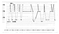
例えば、それぞれ黒実線・黄色実線・赤破線などと、色または線種で区別して、1つのグラフ上に書くとよい。図7は、ダイヤグラム表示の一例を示す図である。 For example, a black solid line, a yellow solid line, and a red broken line may be distinguished from each other by color or line type and written on one graph. FIG. 7 is a diagram illustrating an example of a diagram display.
図7では、上記(1)を黒破線、(2)を黒一点破線、(3)を黒実線で表示している。このようにすることによって、どのような形態で運搬作業を行ったかがわかりやすくなり、特に牽引車のみで移動した時間が長い場合には、それが無駄な作業の可能性があるので、それを削減するように今後の計画に反映させることが可能となる。 In FIG. 7, (1) is indicated by a black broken line, (2) is indicated by a black dashed line, and (3) is indicated by a black solid line. By doing this, it becomes easy to understand what type of transportation work was performed, especially when it is long time to move only by tow truck, it can be wasteful work, so reduce it As a result, it can be reflected in future plans.
なお、表示装置12における表示には、表示専用のプログラムを作成しても良いし、市販の表計算ソフトの散布図を描画する機能を利用して、表計算ソフトにデータを出力することによって輸送ダイヤグラムを作成してもよい。その場合には、散布図は、x軸を年月日時分・y軸を位置として、(1)荷物を積載して輸送した散布図、(2)荷物を運ぶ台車のみ輸送した散布図、(3)何も積載せず移動した散布図の3本の散布図を作成すればよい。
For display on the
1 運行管理システム
2 上位計算機
3 配車計画システム
4 記憶装置
5 製造管理システム
6 車両端末
11 演算装置
12 表示装置
DESCRIPTION OF
Claims (1)
運搬台車を牽引して輸送した際に、その輸送開始時刻・位置の情報、終了時刻・位置の情報、運搬台車に荷物を積載したか否かの情報と、を記憶する記憶装置と、
前記記憶装置から運搬台車を牽引して輸送した際の情報を入力し、該入力した情報から運搬台車を牽引しないで移動した場合の終了時刻・位置と開始時刻・位置とを算出する演算装置と、
前記記憶装置に記憶された情報と前記演算装置で算出された情報を用いて、運搬台車を牽引した荷物を積載して輸送した場合と、運搬台車を牽引したが荷物を積載せず輸送した場合と、運搬台車を牽引しないで移動した場合とを、それぞれ弁別可能な形態で、同一のダイヤグラムに表示する表示装置とを備えることを特徴とする運行管理システム。 An operation management system for managing the operation of a separate vehicle in which a tow vehicle and a carriage can be separated,
A storage device that stores information on the start time / position of the transport, information on the end time / position, information on whether or not a load is loaded on the transport cart, when the transport cart is pulled and transported;
An arithmetic unit that inputs information when transporting the transport cart from the storage device, and calculates an end time / position and a start time / position when moving without pulling the transport cart from the input information; ,
Using the information stored in the storage device and the information calculated by the computing device, when loading and transporting a load that has pulled a transport cart, and when transporting the transport cart that has been pulled but not loaded And a display device for displaying on the same diagram in a form that can be distinguished from each other when the vehicle is moved without towing the carriage.
Priority Applications (1)
| Application Number | Priority Date | Filing Date | Title |
|---|---|---|---|
| JP2008275015A JP5262575B2 (en) | 2008-10-27 | 2008-10-27 | Operation management system |
Applications Claiming Priority (1)
| Application Number | Priority Date | Filing Date | Title |
|---|---|---|---|
| JP2008275015A JP5262575B2 (en) | 2008-10-27 | 2008-10-27 | Operation management system |
Publications (2)
| Publication Number | Publication Date |
|---|---|
| JP2010102597A JP2010102597A (en) | 2010-05-06 |
| JP5262575B2 true JP5262575B2 (en) | 2013-08-14 |
Family
ID=42293176
Family Applications (1)
| Application Number | Title | Priority Date | Filing Date |
|---|---|---|---|
| JP2008275015A Active JP5262575B2 (en) | 2008-10-27 | 2008-10-27 | Operation management system |
Country Status (1)
| Country | Link |
|---|---|
| JP (1) | JP5262575B2 (en) |
Cited By (1)
| Publication number | Priority date | Publication date | Assignee | Title |
|---|---|---|---|---|
| US12049152B2 (en) | 2019-05-27 | 2024-07-30 | Panasonic Intellectual Property Management Co., Ltd. | Information processing method and information processing system for generating a delivery plan using tractor information, trailer information, and delivery information |
Family Cites Families (2)
| Publication number | Priority date | Publication date | Assignee | Title |
|---|---|---|---|---|
| JP2002370808A (en) * | 2001-04-09 | 2002-12-24 | Toyota Industries Corp | Device for analyzing operation efficiency of moving body, and device for monitoring physical distribution condition |
| JP4517735B2 (en) * | 2004-06-08 | 2010-08-04 | Jfeスチール株式会社 | Transportation work planning device and transportation work planning method |
-
2008
- 2008-10-27 JP JP2008275015A patent/JP5262575B2/en active Active
Cited By (1)
| Publication number | Priority date | Publication date | Assignee | Title |
|---|---|---|---|---|
| US12049152B2 (en) | 2019-05-27 | 2024-07-30 | Panasonic Intellectual Property Management Co., Ltd. | Information processing method and information processing system for generating a delivery plan using tractor information, trailer information, and delivery information |
Also Published As
| Publication number | Publication date |
|---|---|
| JP2010102597A (en) | 2010-05-06 |
Similar Documents
| Publication | Publication Date | Title |
|---|---|---|
| Rubio et al. | Multi-objective optimization of costs and energy efficiency associated with autonomous industrial processes for sustainable growth | |
| JP5338305B2 (en) | Vehicle operation plan creation method and apparatus | |
| Battini et al. | Part-feeding with supermarket in assembly systems: transportation mode selection model and multi-scenario analysis | |
| JP5943173B2 (en) | Luggage transport vehicle work flow screen display system and screen display method | |
| Whig et al. | Role of AI and IoT in intelligent transportation | |
| JP6141782B2 (en) | Method for updating map information in a linked system of automated guided vehicle and inventory management system | |
| Saderova et al. | Case study: The simulation modelling of selected activity in a warehouse operation | |
| JP2005104732A (en) | Radio frequency identification tag on picking container and display of pick list for order handling side | |
| JP5446204B2 (en) | Warehouse work planning support device | |
| JP2008021285A (en) | Transportation information management system, transportation information management method, and transportation information management program | |
| JP2011523153A (en) | Vehicle work instruction management system and method | |
| JP6133682B2 (en) | Maritime freight support system at container terminal | |
| Pourmohammad-Zia et al. | Platooning of automated ground vehicles to connect port and hinterland: A multi-objective optimization approach | |
| JP5262575B2 (en) | Operation management system | |
| JP7437839B1 (en) | Logistics management system, logistics management method and program | |
| Bauters et al. | Forklift free factory: a simulation model to evaluate different transportation systems in the automotive industry | |
| Alieksieiev et al. | Towards the improvement of yard management systems (YMS) using radio frequency identification (RFID) | |
| Skender et al. | Intelligent Solutions in the Supply Chains: Challenges for 3PL Providers | |
| JP2020203766A (en) | Delivery supporting system and delivery supporting program | |
| JP2005170579A (en) | Information management system | |
| JP4517735B2 (en) | Transportation work planning device and transportation work planning method | |
| JP5434204B2 (en) | Product transfer work amount prediction apparatus, product transfer work amount prediction method, and computer program | |
| Vahdani et al. | A multi-product vehicle routing scheduling model with time window constraints for cross docking system under uncertainty: A fuzzy possibilistic-stochastic programming | |
| Resat et al. | Design and development of robust optimization model for sustainable cross-docking systems: A case study in electrical devices manufacturing company | |
| Alumbugu et al. | Efficient utilisation of automation in construction materials-handling processes |
Legal Events
| Date | Code | Title | Description |
|---|---|---|---|
| A621 | Written request for application examination |
Free format text: JAPANESE INTERMEDIATE CODE: A621 Effective date: 20110805 |
|
| RD03 | Notification of appointment of power of attorney |
Free format text: JAPANESE INTERMEDIATE CODE: A7423 Effective date: 20120321 |
|
| RD04 | Notification of resignation of power of attorney |
Free format text: JAPANESE INTERMEDIATE CODE: A7424 Effective date: 20120327 |
|
| A977 | Report on retrieval |
Free format text: JAPANESE INTERMEDIATE CODE: A971007 Effective date: 20130322 |
|
| TRDD | Decision of grant or rejection written | ||
| A01 | Written decision to grant a patent or to grant a registration (utility model) |
Free format text: JAPANESE INTERMEDIATE CODE: A01 Effective date: 20130402 |
|
| A61 | First payment of annual fees (during grant procedure) |
Free format text: JAPANESE INTERMEDIATE CODE: A61 Effective date: 20130415 |
|
| R150 | Certificate of patent or registration of utility model |
Free format text: JAPANESE INTERMEDIATE CODE: R150 Ref document number: 5262575 Country of ref document: JP Free format text: JAPANESE INTERMEDIATE CODE: R150 |
|
| R250 | Receipt of annual fees |
Free format text: JAPANESE INTERMEDIATE CODE: R250 |
|
| R250 | Receipt of annual fees |
Free format text: JAPANESE INTERMEDIATE CODE: R250 |
|
| R250 | Receipt of annual fees |
Free format text: JAPANESE INTERMEDIATE CODE: R250 |
|
| R250 | Receipt of annual fees |
Free format text: JAPANESE INTERMEDIATE CODE: R250 |
|
| R250 | Receipt of annual fees |
Free format text: JAPANESE INTERMEDIATE CODE: R250 |