JP5262046B2 - Dry cell, method for manufacturing the same, and apparatus for manufacturing the same - Google Patents
Dry cell, method for manufacturing the same, and apparatus for manufacturing the same Download PDFInfo
- Publication number
- JP5262046B2 JP5262046B2 JP2007254022A JP2007254022A JP5262046B2 JP 5262046 B2 JP5262046 B2 JP 5262046B2 JP 2007254022 A JP2007254022 A JP 2007254022A JP 2007254022 A JP2007254022 A JP 2007254022A JP 5262046 B2 JP5262046 B2 JP 5262046B2
- Authority
- JP
- Japan
- Prior art keywords
- positive electrode
- electrode material
- battery case
- battery
- electrolyte
- Prior art date
- Legal status (The legal status is an assumption and is not a legal conclusion. Google has not performed a legal analysis and makes no representation as to the accuracy of the status listed.)
- Active
Links
Images


Classifications
-
- Y02E60/12—
Abstract
Description
本発明は、アルカリマンガン乾電池に代表される乾電池の発電要素である正極材に電解液を流入促進および電解液の保持を行うための改良した乾電池に関するのである。 The present invention relates to an improved dry battery for facilitating the inflow of electrolyte and holding the electrolyte in a positive electrode material that is a power generation element of a dry battery represented by an alkaline manganese dry battery.
近年、強負荷の放電性能を必要とされる電子機器、例えばデジタルスチルカメラ等のように、消費電力の大きな高負荷機器が多く市場に普及してきている。これに伴い、電池、特にアルカリマンガン乾電池の放電性能の向上が求められている。 In recent years, there are many high-load devices that consume large amounts of power, such as electronic devices that require high-load discharge performance, such as digital still cameras, and have spread to the market. In connection with this, the improvement of the discharge performance of a battery, especially an alkali manganese dry battery is calculated | required.
具体的にアルカリマンガン乾電池について説明する。アルカリマンガン乾電池は、正極材、負極材、電解液、セパレータ、封口板、および有底円筒状の電池ケースとを備え、放電性能向上の取り組みとして、限られた電池ケース内の内容積を有効利用して、活物質を可能な限り多く収納するため正極材を圧縮成形する際に加圧力を高く設定して高密度の正極材を作製し、正極材の増量が可能となったが、高密度に成形した正極材のため、成形した内部の空隙体積が減少して電解液の含浸に長時間を要し、電解液の吸液含浸量が少なくなる傾向となった。 Specifically, the alkaline manganese battery will be described. Alkaline manganese batteries are equipped with a positive electrode material, negative electrode material, electrolyte, separator, sealing plate, and bottomed cylindrical battery case. As an effort to improve discharge performance, the internal volume within the limited battery case is effectively utilized. In order to accommodate as much of the active material as possible, when the positive electrode material is compression-molded, the pressure force is set high to produce a high-density positive electrode material. Therefore, the void volume inside the molded electrode was reduced, and it took a long time to impregnate the electrolyte solution, and the amount of the electrolyte solution absorbed and impregnated tended to decrease.
そのことで、電池ケース内の電解液が不足気味になるため、電池ケース内に封入された活物質の有効利用率が横ばい、ないし低下の傾向となり、活物質の利用率が低下するとともに、高負荷放電性能が低下してしまうという問題が生じる。 As a result, the electrolyte in the battery case becomes insufficient, so that the effective utilization rate of the active material enclosed in the battery case is flat or tends to decrease, the utilization rate of the active material decreases, and The problem that load discharge performance will fall arises.
そこで、電解液を正極材に多く吸液含浸させることで電池内の活物質の利用率が上がり、放電性能を向上させるための電解液を多く吸液含浸させる方法として、図8に示すように、最初から空隙を有する中空正極材ペレット101の形成に際して、高強度な合剤102と合剤103とを固結させ、合剤102と合剤103の間に空隙を持たせた中空円筒状の正極材101を形成している。高強度な合剤102は、合剤103より高密度で高強度になるように形成するために、次に述べるような造粒工程が必要である。高強度な合剤102を造粒するために、合剤材料にロール圧延機で線圧6t/cmの圧力を加え、解砕機で粉砕し、そして篩分けして作られる。
Therefore, as shown in FIG. 8, a method of absorbing and impregnating a large amount of electrolyte for improving the discharge performance by increasing the amount of electrolyte in the positive electrode material by absorbing and impregnating the positive electrode material increases the utilization rate of the active material in the battery. In the formation of the hollow
高強度な合剤102は、電解液を含浸しても、造粒時に形成された形状をほぼそのまま保持することができ、高強度な合剤102より低強度な合剤103は、電解液を含浸した時に、膨潤して微小亀裂が生じる。電解液が微小亀裂を通して高強度な合剤102に満遍なく行き渡ることにより、正極材101の全体としても多量の電解液を均等に含浸することができる。これにより、正極材101が電解液の含浸前に有していた空隙の体積より多い電解液が含浸されるようになることが提案されている(例えば、特許文献1参照)。
しかしながら、上述した特許文献に示される従来技術では、正極材101に電解液が含浸させると全体に微小亀裂が形成され、その微小亀裂に電解液が保持される。その条件として正極材にまず電解液を吸液させる必要があり、電解液の吸液に長時間を要し、電解液の吸液含浸量が少なくなる課題が発生する。さらに、高強度な合剤102を使用しているため高密度の正極材を圧縮成形するのが困難な上、その高強度な合剤102を作製するために、高強度の圧延機が必要となるため、生産性が低下する。
However, in the prior art disclosed in the above-described patent document, when the
本発明は、上述の従来の課題を鑑みてなされたもので、正極材の電解液を吸液含浸する性能を向上させ、電池内の活物質の利用率を向上させて乾電池の放電性能を向上させることを目的とするものである。 The present invention has been made in view of the above-described conventional problems, and improves the performance of absorbing and impregnating the electrolyte solution of the positive electrode material, improves the utilization rate of the active material in the battery, and improves the discharge performance of the dry battery. The purpose is to make it.
上記目的を達成するために本発明の乾電池は、正極材と、負極材と、この正極材と負極材と間に介在されたセパレータと電解液を電池ケースに収納し、電池ケースの開口部を封口体で密閉した乾電池において、正極材を中空状に圧縮成形し、正極材の内壁に電解液を流入促進および電解液の保持を行うためのクラックを成形したことを特徴としている。
In order to achieve the above object, the dry battery of the present invention contains a positive electrode material, a negative electrode material, a separator interposed between the positive electrode material and the negative electrode material, and an electrolytic solution in a battery case, and an opening of the battery case is provided. A dry battery sealed with a sealing body is characterized in that a positive electrode material is compression-molded into a hollow shape, and a crack is formed on the inner wall of the positive electrode material for promoting the inflow of the electrolyte and holding the electrolyte.
本発明の電池は、正極材の表面に電解液を流入促進および電解液の保持を行うためのクラックを成形したにより、高密度に圧縮成形した正極材にも関わらず、正極材の表面に成形したクラックに電解液の流入促進および保持を行うため、放電時に電解液が枯れることを抑制し、電池ケース内の活物質の利用率を向上させて乾電池の放電性能を向上させることが可能である。 The battery of the present invention is formed on the surface of the positive electrode material in spite of the positive electrode material that is compression-molded at a high density by forming a crack on the surface of the positive electrode material for promoting the inflow of the electrolyte and holding the electrolyte. It is possible to improve the discharge performance of the dry battery by suppressing the electrolyte from dying during discharge and improving the utilization rate of the active material in the battery case. .
本発明の第1の発明においては、正極材と、負極材と、この正極材と負極材と間に介在されたセパレータと電解液を電池ケースに収納し、電池ケースの開口部を封口体で密閉した乾電池において、正極材の表面に電解液を流入促進および電解液の保持を行うためのクラックを成形したことにより、電解液が枯れることを抑制し、電池ケース内の活物質の利用率を向上させて電池の高負荷放電性能を向上した乾電池となる。 In the first aspect of the present invention, the positive electrode material, the negative electrode material, the separator interposed between the positive electrode material and the negative electrode material, and the electrolyte are stored in the battery case, and the opening of the battery case is sealed with a sealing body. In a sealed dry battery, by forming a crack on the surface of the positive electrode material to promote the inflow of the electrolyte and to hold the electrolyte, the electrolyte is prevented from withstanding, and the utilization rate of the active material in the battery case is increased. It becomes the dry battery which improved and improved the high load discharge performance of the battery.
本発明の第2の発明においては、正極材を中空状に圧縮成形し、正極材の内壁にクラックを成形したことにより、電解液を正極材の中空部に注液することで、正極材の内壁のクラックより電解液が敏速に流入され、電解液の吸液含浸量が増加し高負荷放電性能が向上した乾電池となる。 In the second invention of the present invention, the positive electrode material is compression-molded into a hollow shape, and cracks are formed in the inner wall of the positive electrode material, thereby pouring the electrolyte into the hollow portion of the positive electrode material. The electrolyte is promptly flowed from the cracks on the inner wall, and the amount of liquid electrolyte impregnated is increased, resulting in a dry battery with improved high-load discharge performance.
本発明の第3の発明においては、二酸化マンガンからなる中空円筒状に圧縮成形した正極合剤を用いた正極材を有底円筒状からなる電池ケースに収納し、電池ケースの中間部より有底部近傍側の正極材の内壁にクラックを成形したことにより、電池ケースの有底部から中間部位置付近までの量を注液した電解液を効率よく、正極材の内壁のクラックから吸液含浸が可能となり、放電時に電解液が枯れることのない乾電池となる。 In the third invention of the present invention, a positive electrode material using a positive electrode mixture compression-molded into a hollow cylindrical shape made of manganese dioxide is housed in a battery case having a bottomed cylindrical shape, and a bottomed portion is formed from an intermediate portion of the battery case. By forming cracks on the inner wall of the positive electrode material on the nearby side, it is possible to efficiently impregnate the electrolyte that has been injected in an amount from the bottom of the battery case to the vicinity of the middle position, from the crack on the inner wall of the positive electrode material. Thus, a dry battery is obtained in which the electrolytic solution does not wither during discharge.
本発明の第4の発明においては、複数個からなる中空円筒状の正極材を有底円筒状の電池ケースに収納し、電池ケースの中間部より有底部近傍側に位置する正極材の内壁にクラックを成形したことにより、複数個使用した正極材のうち電解液が浸っている正極材の内壁に成形したクラックより効率よく電解液を吸液含浸が可能となり、放電特性が向上した乾電池となる。 In the fourth aspect of the present invention, a plurality of hollow cylindrical positive electrode materials are housed in a bottomed cylindrical battery case, and the inner wall of the positive electrode material is located closer to the bottomed portion than the middle portion of the battery case. By forming the crack, it becomes possible to absorb and impregnate the electrolyte more efficiently than the crack formed on the inner wall of the positive electrode material in which the electrolyte solution is immersed among the plurality of positive electrode materials used, resulting in a dry battery with improved discharge characteristics. .
本発明の第5の発明においては、有底形状からなる電池ケースに正極材と負極材とそれらの間にセパレータを介入して収納後、電解液とともに収納し、封口体を介してかしめ封口する乾電池の製造方法において、正極合剤を中空状に圧縮成形して正極材を構成し電池ケース内に収納後、正極材に押圧をかけて正極材の内壁に電解液を流入促進および電解液の保持を行うためのクラックを成形することにより、効率よく正極材の内壁に成形したクラックより電解液が流入し、吸液含浸時間の削減が可能となる。 In the fifth aspect of the present invention, the positive electrode material, the negative electrode material, and the separator interposed between them are stored in the battery case having a bottomed shape, and then stored together with the electrolytic solution, and caulked and sealed through the sealing body. In the method of manufacturing a dry battery, the positive electrode mixture is compressed into a hollow shape to form a positive electrode material, and the positive electrode material is stored in the battery case. Then, the positive electrode material is pressed and the electrolyte solution is allowed to flow into the inner wall of the positive electrode material. By forming a crack for holding, the electrolytic solution efficiently flows from the crack formed on the inner wall of the positive electrode material, and it is possible to reduce the liquid absorption impregnation time.
本発明の第6の発明においては、中空円筒状に正極材を成形し有底円筒状に構成した電池ケースの開口部より正極材を収納し、電池ケースの中間部より開口部近傍の中空円筒状
である正極材の内壁を保持し、電池ケースの開口部側より正極材に押圧をかけ、電池ケースの中間部より有底部近傍側の保持していない正極材の内壁にクラックを成形することにより、電池ケースの有底部から中間部位置付近までの量を注液した電解液を効率よく、正極材の内壁のクラックから含浸可能となり、吸液含浸時間の削減が可能となる。
In the sixth aspect of the present invention, the positive electrode material is molded into a hollow cylindrical shape, and the positive electrode material is accommodated from the opening portion of the battery case configured in a bottomed cylindrical shape, and the hollow cylinder near the opening portion from the middle portion of the battery case. Holding the inner wall of the positive electrode material, pressing the positive electrode material from the opening side of the battery case, and forming cracks on the inner wall of the unsupported positive electrode material near the bottomed part from the middle part of the battery case As a result, it is possible to efficiently impregnate the electrolytic solution in which the amount from the bottomed portion of the battery case to the vicinity of the intermediate portion is impregnated from cracks on the inner wall of the positive electrode material, and it is possible to reduce the liquid absorption impregnation time.
本発明の第7の発明においては、有底円筒形状の電池ケースの開口部より中空円筒状の正極材とゲル状の負極材とを筒状のセパレータを介して電解液とともに収納した後、電池ケースの開口部に封口体を載置して、かしめ封口する乾電池の製造装置において、正極材を収納した電池ケースを搬入する搬入部と搬入した電池ケースを保持するカートリッジと電池ケースに収納された正極材の中空部に挿入する挿入ピンと正極材に押圧をかける上パンチと電池ケースの有底部より押圧の反力を支える下パンチと次工程に搬送する搬送部とで構成したことにより、電池ケースの有底部から中間部位置付近までに位置する正極材の内壁のクラックを効率よく形成することが可能で、生産性の向上が可能となる。 In the seventh invention of the present invention, after the hollow cylindrical positive electrode material and the gel negative electrode material are accommodated together with the electrolyte solution through the cylindrical separator from the opening of the bottomed cylindrical battery case, the battery In a dry battery manufacturing apparatus in which a sealing body is placed in a case opening and caulked and sealed, a battery case containing a positive electrode material is carried in, a cartridge holding the battery case carried in and a battery case housed in the battery case A battery case comprising an insertion pin to be inserted into the hollow portion of the positive electrode material, an upper punch that presses against the positive electrode material, a lower punch that supports the reaction force of the pressure from the bottomed portion of the battery case, and a transport portion that is transported to the next process It is possible to efficiently form cracks on the inner wall of the positive electrode material located from the bottomed portion to the vicinity of the intermediate portion position, and productivity can be improved.
本発明の第8の発明においては、挿入ピンの胴体部の直径より先端部の直径が細い構成にしたことにより、正極材の内壁を保持する部分と保持しない部分を設け、正極材の電解液が接する部分のみにクラックを容易に成形することが可能となる。 In the eighth invention of the present invention, the tip portion has a smaller diameter than the diameter of the body portion of the insertion pin, thereby providing a portion for holding the inner wall of the positive electrode material and a portion not holding the positive electrode material. It is possible to easily form a crack only in a portion where the contact is made.
本発明の第9の発明においては、挿入ピンの形状がテーパー状である構成にしたことにより、電池ケースの有底部近傍に配置した正極材の内壁に電解液の流入促進を向上できるクラックを容易に成形することが可能となる。 In the ninth aspect of the present invention, since the shape of the insertion pin is tapered, a crack that can improve the inflow of the electrolytic solution to the inner wall of the positive electrode material arranged near the bottomed portion of the battery case is easy. It becomes possible to mold into.
本発明の第10の発明においては、挿入ピンに回転を掛けながら、正極材より離脱する構成にしたことにより、正極材より挿入ピンを効率よく、正極材にダメージなく抜くことが可能となる。 In the tenth aspect of the present invention, the insertion pin can be efficiently pulled out from the positive electrode material without damage to the positive electrode material by adopting a configuration in which the insertion pin is detached from the positive electrode material while rotating the insertion pin.
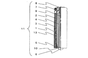
以下、本発明の一実施の形態であるアルカリマンガン乾電池の構成について、図を参照して説明する。図1に示すように、有底部10に正極凸部6を設け有底円筒状に形成した正極端子一体型の電池ケース1に電池ケース1の内周面に接する中空円筒形状に圧縮成形した正極材2が収容され、この正極材2の内壁方向に底部セパレータ5と筒状セパレータ3で隔てられた電解液(図示せず)とゲル状の負極材4が収容されている。
Hereinafter, the configuration of an alkaline manganese dry battery according to an embodiment of the present invention will be described with reference to the drawings. As shown in FIG. 1, a positive electrode terminal-integrated
また、正極材2の内壁の表面に電解液を流入促進および電解液の保持を行うためのクラック13が成形されている。さらに、電池ケース1の開口端は絶縁ガスケット7を介して、封口板8によって封口されると共にゲル状の負極材4に挿入した負極集電棒9を接続し負極端子となる封口板8が取り付けられて円筒形のアルカリマンガン乾電池11を構成している。
Further, a
アルカリマンガン乾電池11の品種により収納する中空円筒形状に圧縮成形した正極材2を複数個積み重ねて収納し、本発明の一実施の形態においては電池ケース1内に4個の正極材2を収納する。なお、電池ケース1の高さに合わせて、複数個、例えば2〜6個の正極材2を入れてもよい。電池ケース1の高さが低い場合、例えば正極材2の高さと電池ケース1の高さとがほぼ同等の場合など、1個の正極材2の収納となる。
A plurality of
さらに、本発明の実施の形態に関わる乾電池の構成および製造方法について、説明する。以下に示される構成および製造方法については、本発明を説明するために掲げた例えば外径14mm、高さ50mmのアルカリマンガン乾電池であるLR6として一例を示すものであって、本発明の乾電池の構造を下記のものに特定するものではない。また、中空状に圧縮成形した正極材の形状は円筒状または方形でよい。 Furthermore, the structure and manufacturing method of the dry cell concerning embodiment of this invention are demonstrated. About the structure and manufacturing method shown below, an example is shown as LR6 which is an alkaline manganese dry battery having an outer diameter of 14 mm and a height of 50 mm listed for explaining the present invention, and the structure of the dry battery of the present invention Is not specified as follows. Moreover, the shape of the positive electrode material compression-molded into a hollow shape may be cylindrical or rectangular.
まず、図1に示すように有底円筒状に形成した電池ケース1の有底部10には、正極端子となる外方に向けて突出した正極凸部6が設けられ、電池ケース1内に、粉末状の正極合剤を中空円筒状に圧縮成形した正極材2を電池ケース1の内周面に接した状態で挿入し収納する。また、アルカリマンガン乾電池11の品種により収納する中空円筒状の正極材2を複数個収納し、本発明の一実施の形態においては電池ケース1内に4個の正極材2を収納する。
First, as shown in FIG. 1, the bottomed
なお、正極合剤は二酸化マンガンと黒鉛とを90:10の重量比で混合した混合物とアルカリ電解液とを100:3の重量比で混合し、十分に攪拌した後、フレーク状に圧縮成形した。また、アルカリ電解液には、40重量%の水酸化ナトリウム水溶液を用い、フレーク状の正極合剤を粉砕して粉末状にしてふるいによって分級し、10〜100メッシュのものを中空円筒形状に圧縮成形して正極材2を作製した。
The positive electrode mixture was prepared by mixing a mixture of manganese dioxide and graphite in a weight ratio of 90:10 and an alkaline electrolyte in a weight ratio of 100: 3, sufficiently stirring, and then compression-molding into flakes. . In addition, 40% by weight sodium hydroxide aqueous solution is used as the alkaline electrolyte, and the flaky positive electrode mixture is pulverized, powdered and classified by sieving, and 10 to 100 mesh is compressed into a hollow cylindrical shape. The
ここで電池ケース1に収納された正極材2に電池ケース1の開口部より押圧をかける。正極材2に圧縮力が作用し、縦方向および横方向に分散された押圧が正極材2の表面に微細な割れ目であるクラックを成形し、本願の電解液の流入促進および電解液の保持を行うためのクラックを成形する。
Here, the
次に、底部セパレータ5が筒状セパレータ3を包み込んだ状態で正極材2の内壁に密着させて装着する。なお、底部セパレータ5はイオンのみを透過する微孔性フィルムとして再生セルロースを用い、その両面に化学繊維からなる不織布をラミネートしており、0.02から0.3mm厚みである。
Next, the
その後、図1の構造を表示したように電解液(図示せず)を注液した後、吸液含浸する時間放置する。電解液は筒状セパレータ3および底部セパレータ5を透過して正極材2の内壁に接触する。正極材2の内壁に接触した電解液は成形したクラックより正極材2の内部へと流入し、正極材2の内部に保持される。
Thereafter, an electrolyte solution (not shown) is injected as shown in the structure of FIG. The electrolyte passes through the
多くの電解液を吸液含浸した正極材2は放電時、電解液が枯れることなく活物質が利用される。このことで活物質の有効利用率が向上し、高負荷放電性能が向上した乾電池となる。
The
次にゲル状になった負極材4を注入した後、周縁に絶縁ガスケット7が装着され中央部に負極集電棒9を設けた負極端子となる封口板8の負極集電棒9を負極材4に挿入しながら、電池ケース1の開口部に装着して、電池ケース1の開口部を内側方向に折り曲げてかしめ封口し密閉した乾電池を作製する。
Next, after the gelled negative electrode material 4 is injected, the negative electrode
なお、ゲル状の負極材4はゲル化剤としてポリアクリル酸ナトリウムと、アルカリ電解液として40重量%の水酸化ナトリウム水溶液と、負極活物質として亜鉛粉末とを1:33:66の重量比で混合している。 Note that the gelled negative electrode material 4 comprises sodium polyacrylate as a gelling agent, a 40 wt% aqueous sodium hydroxide solution as an alkaline electrolyte, and zinc powder as a negative electrode active material in a weight ratio of 1:33:66. Mixed.
(実施の形態)
以下に、本発明の実施の形態について、図を参照しながら説明する。図2(a)に示すように粉末状の正極合剤21が充填され、図2(b)に示すように正極合剤21が圧縮成形されて、図3に示す圧縮成形した正極材2を電池ケース1に収納して次工程に搬送する。
(Embodiment)
Embodiments of the present invention will be described below with reference to the drawings. The powdered
次工程では、図4に示すように電池ケース1を搬入する搬入部である搬入コンベア41がカートリッジ33に接続され、カートリッジ33には正極材2の内壁12にクラック13を成形するクラック成形部30が配置されている。駆動部42でカートリッジ33を駆
動し、カートリッジ33の出口には搬送部である電池ケース1を搬送する搬送コンベア43が接続され、次工程に搬送される。
In the next step, as shown in FIG. 4, a carry-in
次工程で図1に示すようにクラック13を内壁12に成形した正極材2の中空部に底部セパレータ5と筒状セパレータ3とが装着された後、電解液(図示せず)を注液し、ゲル状の負極材4を収容する。その後、電池ケース1の開口端は絶縁ガスケット7を介して、ゲル状の負極材4に挿入した負極集電棒9を接続し負極端子となる封口板8を載置し、電池ケース1の開口端をかしめ封口してアルカリマンガン乾電池11を作製する。
In the next step, as shown in FIG. 1, after the
図2(a)は、粉末状の正極合剤21を成型金型であるダイス22に充填した時の正面の概略断面図である。中空状のダイス22内に成型下パンチ24を配置し、成型下パンチ24の中央部より円柱形状のセンターピン3を突き出した位置で配置する。ダイス22と成型下パンチ24とセンターピン23で構成した筒状の空間に規定量の正極合剤21を充填する。
FIG. 2A is a schematic cross-sectional view of the front when the powdered
その後、図2(b)に示すようにダイス22の開口部より成型上パンチ25を挿入し、成型上パンチ25と成型下パンチ24が近づく方向に移動させて、正極合剤21に加重をかけ、高密度な中空円筒状に圧縮成形した正極材2を作製した。次に成型上パンチ25をダイス22より離脱させ、成型下パンチ24を突き上げて、正極材2をダイス22より取り出した後、図3に示すように正極材2をアルカリマンガン乾電池11の品種により異なるが、本実施の形態では4個を電池ケース1に収納し、次工程に搬送する。
Thereafter, as shown in FIG. 2 (b), the
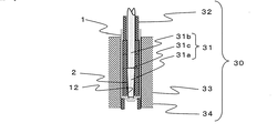
次工程の乾電池の製造装置で、図4に示すように正極材2を収納した電池ケース1が搬入コンベア41により搬入され、カートリッジ33に搬入した電池ケース1がクラック成形部30の位置まで搬送されて、クラック成形部30では図5に示すようにカートリッジ33の孔内に配置した電池ケース1の有底部10側より下パンチ34で支え、挿入ピン31を電池ケース1に収納した正極材2の中空部内に挿入する。
In the dry battery manufacturing apparatus in the next step, as shown in FIG. 4, the
挿入ピン31は図6に示すように先端部31aが胴体部31bより細い形状が好ましく、境界部31cの位置で正極材2のクラック13を成形する個所を制御することが可能となる。即ち、境界部31cを先端部31aの先端に近づけることで、クラック13の成形する個所が電池ケースの中間部より有底部10の近傍側の方向に近づくこととなる。
As shown in FIG. 6, the
図5に示すように挿入ピン31の胴体部31bの外径を正極材2の内径に近い寸法とし、電池ケース1の中間部より開口部近傍に位置する中空円筒状である正極材2の内壁12を保持し、境界部31cは電池ケース1の中間部、例えば収納した正極材2の半分の高さ位置になる位置で配置している。即ち、4個収納した正極材2の2個目と3個目の間に位置する位置で境界部31cを配置し、図5の挿入ピン31では先端部31aは先端が細くなるテーパー形状をしている。この挿入ピン31の形状により挿入ピン31の胴体部31bと正極材2の内壁12とが接触している箇所と、先端部31aでは正極材2の内壁12と接触していない個所とになる。
As shown in FIG. 5, the outer diameter of the
次に上パンチ32で正極材2に押圧をかける。正極材2にかけた押圧は圧縮力として作用し、電池ケース1の有底部10を介して下パンチ34で反力として支えられ、正極材2の中で分散される。縦方向の押圧は下パンチ34で反力として支えられ、横方向に分散した押圧である正極材2の外径方向に作用した押圧は電池ケース1の内径で反力として支えられる。
Next, the
また、正極材2の内径方向に作用した押圧は、挿入ピン31の胴体部31bと正極材2の内壁12とが接触している箇所において、挿入ピン31の胴体部31bの外径で反力と
して支えられ、テーパー形状の先端部31aでは正極材2の内壁12と接触していない個所とになるので、反力として支えられない。
In addition, the pressure applied in the inner diameter direction of the
挿入ピン31の胴体部31bでは、正極材2の内径方向に作用した押圧が胴体部31bの外径が反力として支えられて、クラック13を成形しないが、挿入ピン31の先端部31aでは、反力として支える部分がないため、押圧が正極材2の内径方向に作用し、正極材2の内壁12にクラック13を成形する。
In the
その後、上パンチ32を正極材2の離接方向に移動し、挿入ピン31も正極材2の内径より抜く。この際、挿入ピン31に回転を掛けながら抜くことにより、挿入ピン31が正極材2より容易に抜くことが可能となる。
Thereafter, the
図7は、正極材2の4個のうち、2個の正極材2の内壁12にクラック13を成形した正極材2を収納した電池ケース1の断面図を示す。
FIG. 7 shows a cross-sectional view of the
この電池ケース1を次工程において、底部セパレータ5が筒状セパレータ3を包み込んだ状態で正極材2の内壁12に密着させて装着後、電池ケース1の開口部より電解液を電池ケース1の有底部10から中間位置付近までの量を注液する。吸液含浸する時間放置した正極材2の内壁12に筒状セパレータ3および底部セパレータ5を透過した電解液が接触し、正極材2の内壁12に接触した電解液が成形したクラック13より正極材2の内部へと流入し、正極材2の内部に保持される。
In the next process, the
このように正極材2の表面に電解液を流入促進および電解液の保持を行うためのクラック13を成形したにより、吸液含浸量が少なくなる傾向が抑制され、乾電池の放電時に電解液が枯れることを抑制し、電池ケース内の活物質の利用率を向上させて放電性能を向上させることが可能となる。また、高密度に中空状に圧縮成形した正極材2にも関わらず、電解液の流入促進されているため、吸液含浸時間の長時間を要することがなくなり短縮が図れ、生産性の向上が可能となる。
Thus, by forming the
また、従来のような高強度の合剤粒102を作る工程が不要になるため、乾電池の生産性を向上させることができる。なお、本発明の実施の形態における乾電池は、アルカリマンガン乾電池、マンガン乾電池、ニッケル系一次電池(代表例として、オキシライド乾電池が挙げられる)などがある。また、乾電池の形状については、円筒形と角形の形状の乾電池に適用できる。
Moreover, since the process of making the high intensity |
本発明の乾電池は、高密度に圧縮成形された正極材への電解液の流入促進および保液性を向上したことで、放電性能と生産性を向上させることができるため、強負荷の放電性能を必要とされる電子機器や多く市場に普及してきている消費電力の大きな高負荷機器の対応した乾電池として有用である。 The dry battery of the present invention can improve discharge performance and productivity by improving the inflow promotion and liquid retention of the electrolyte solution to the positive electrode material that has been compression-molded at a high density. It is useful as a dry battery for electronic devices that require high power consumption and high load devices with large power consumption that have been widely used in the market.
1 電池ケース
2 正極材
3 筒状セパレータ
4 負極材
5 底部セパレータ
6 正極凸部
7 絶縁ガスケット
8 封口板
9 負極集電棒
10 有底部
11 アルカリマンガン乾電池
12 内壁
13 クラック
21 正極合剤
22 ダイス
23 センターピン
24 成型下パンチ
25 成型上パンチ
30 クラック成形部
31 挿入ピン
31a 先端部
31b 胴体部
31c 境界部
32 上パンチ
33 カートリッジ
34 下パンチ
41 搬入コンベア
42 駆動部
43 搬送コンベア
DESCRIPTION OF
Claims (9)
納された正極材の中空部に挿入する挿入ピンと前記正極材に押圧をかける上パンチと前記電池ケースの有底部より押圧の反力を支える下パンチと次工程に搬送する搬送部とで構成したことを特徴とする乾電池の製造装置。 After storing the hollow cylindrical positive electrode material and the gel negative electrode material together with the electrolyte solution through the cylindrical separator from the opening of the bottomed cylindrical battery case, a sealing body is mounted on the opening of the battery case. In a dry battery manufacturing apparatus that is placed and caulked and sealed, a loading part for carrying in the battery case containing the positive electrode material, a cartridge for holding the carried battery case, and a hollow part of the positive electrode material housed in the battery case An apparatus for manufacturing a dry cell, comprising: an insertion pin to be inserted; an upper punch that presses against the positive electrode material; a lower punch that supports a reaction force from the bottom of the battery case; .
Priority Applications (1)
| Application Number | Priority Date | Filing Date | Title |
|---|---|---|---|
| JP2007254022A JP5262046B2 (en) | 2007-09-28 | 2007-09-28 | Dry cell, method for manufacturing the same, and apparatus for manufacturing the same |
Applications Claiming Priority (1)
| Application Number | Priority Date | Filing Date | Title |
|---|---|---|---|
| JP2007254022A JP5262046B2 (en) | 2007-09-28 | 2007-09-28 | Dry cell, method for manufacturing the same, and apparatus for manufacturing the same |
Publications (2)
| Publication Number | Publication Date |
|---|---|
| JP2009087636A JP2009087636A (en) | 2009-04-23 |
| JP5262046B2 true JP5262046B2 (en) | 2013-08-14 |
Family
ID=40660816
Family Applications (1)
| Application Number | Title | Priority Date | Filing Date |
|---|---|---|---|
| JP2007254022A Active JP5262046B2 (en) | 2007-09-28 | 2007-09-28 | Dry cell, method for manufacturing the same, and apparatus for manufacturing the same |
Country Status (1)
| Country | Link |
|---|---|
| JP (1) | JP5262046B2 (en) |
Families Citing this family (1)
| Publication number | Priority date | Publication date | Assignee | Title |
|---|---|---|---|---|
| CN114203959B (en) * | 2021-12-13 | 2024-01-23 | 东莞新能安科技有限公司 | Electrode assembly, electrochemical device, and electronic device |
Family Cites Families (4)
| Publication number | Priority date | Publication date | Assignee | Title |
|---|---|---|---|---|
| JP2005302528A (en) * | 2004-04-12 | 2005-10-27 | Matsushita Electric Ind Co Ltd | Alkaline dry battery |
| JP2006012493A (en) * | 2004-06-23 | 2006-01-12 | Matsushita Electric Ind Co Ltd | Alkaline battery |
| JP4388426B2 (en) * | 2004-06-30 | 2009-12-24 | パナソニック株式会社 | Alkaline battery |
| JP5260821B2 (en) * | 2005-07-11 | 2013-08-14 | パナソニック株式会社 | Lithium ion secondary battery |
-
2007
- 2007-09-28 JP JP2007254022A patent/JP5262046B2/en active Active
Also Published As
| Publication number | Publication date |
|---|---|
| JP2009087636A (en) | 2009-04-23 |
Similar Documents
| Publication | Publication Date | Title |
|---|---|---|
| US7851087B2 (en) | Enclosed nickel-zinc primary battery, its anode and production methods for them | |
| JP5587438B2 (en) | Alkaline battery | |
| JP4667483B2 (en) | Alkaline battery and method for producing the same | |
| US3427203A (en) | Large surface area electrodes and a method for preparing them | |
| JP6078333B2 (en) | Alkaline battery and method for producing alkaline battery | |
| JP5262046B2 (en) | Dry cell, method for manufacturing the same, and apparatus for manufacturing the same | |
| JP3341693B2 (en) | Active material powder for electrode of silver oxide battery, electrode material and production method thereof | |
| JP5849228B2 (en) | Alkaline battery | |
| JP3192105B2 (en) | Positive electrode mixture for alkaline batteries | |
| JP2008004302A (en) | Manufacturing method of lithium secondary battery | |
| CN205960127U (en) | Lithium ion battery | |
| JP2006179449A (en) | Manufacturing method of electrode plate for lead-acid storage battery | |
| JP6443725B2 (en) | Porous aluminum sintered body, method for producing the same, and method for producing an electrode | |
| JP2009087803A (en) | Electrochemical element, and method and device for manufacturing the same | |
| JP2000294233A (en) | Manufacture of positive electrode mix for alkaline dry battery | |
| JP4739493B2 (en) | Positive electrode mixture molded body and battery | |
| WO2011001603A1 (en) | Alkali dry cell | |
| JP4357191B2 (en) | Sealed nickel zinc primary battery and manufacturing method thereof | |
| JP2009164060A (en) | Electrochemical element and its manufacturing method | |
| US20090291362A1 (en) | Flat-type alkaline primary battery | |
| JP2007250451A (en) | Alkaline cell | |
| JPH1027604A (en) | Battery mix molding method | |
| JPH04229556A (en) | Plate for lead-acid battery | |
| JPS5928025B2 (en) | Alkaline battery manufacturing method | |
| JPH1012245A (en) | Manufacture of alkaline dry battery |
Legal Events
| Date | Code | Title | Description |
|---|---|---|---|
| A621 | Written request for application examination |
Free format text: JAPANESE INTERMEDIATE CODE: A621 Effective date: 20100715 |
|
| RD01 | Notification of change of attorney |
Free format text: JAPANESE INTERMEDIATE CODE: A7421 Effective date: 20100806 |
|
| RD01 | Notification of change of attorney |
Free format text: JAPANESE INTERMEDIATE CODE: A7421 Effective date: 20121213 |
|
| A131 | Notification of reasons for refusal |
Free format text: JAPANESE INTERMEDIATE CODE: A131 Effective date: 20130108 |
|
| A521 | Written amendment |
Free format text: JAPANESE INTERMEDIATE CODE: A523 Effective date: 20130305 |
|
| TRDD | Decision of grant or rejection written | ||
| A01 | Written decision to grant a patent or to grant a registration (utility model) |
Free format text: JAPANESE INTERMEDIATE CODE: A01 Effective date: 20130402 |
|
| A61 | First payment of annual fees (during grant procedure) |
Free format text: JAPANESE INTERMEDIATE CODE: A61 Effective date: 20130415 |
|
| R151 | Written notification of patent or utility model registration |
Ref document number: 5262046 Country of ref document: JP Free format text: JAPANESE INTERMEDIATE CODE: R151 |