JP5260063B2 - Ventilation board, ventilation box, ventilation system, heat insulation board, and ventilation board and method of manufacturing ventilation box - Google Patents
Ventilation board, ventilation box, ventilation system, heat insulation board, and ventilation board and method of manufacturing ventilation box Download PDFInfo
- Publication number
- JP5260063B2 JP5260063B2 JP2007555778A JP2007555778A JP5260063B2 JP 5260063 B2 JP5260063 B2 JP 5260063B2 JP 2007555778 A JP2007555778 A JP 2007555778A JP 2007555778 A JP2007555778 A JP 2007555778A JP 5260063 B2 JP5260063 B2 JP 5260063B2
- Authority
- JP
- Japan
- Prior art keywords
- ventilation
- board
- layer
- box
- passage
- Prior art date
- Legal status (The legal status is an assumption and is not a legal conclusion. Google has not performed a legal analysis and makes no representation as to the accuracy of the status listed.)
- Expired - Fee Related
Links
Images


Classifications
-
- B—PERFORMING OPERATIONS; TRANSPORTING
- B65—CONVEYING; PACKING; STORING; HANDLING THIN OR FILAMENTARY MATERIAL
- B65D—CONTAINERS FOR STORAGE OR TRANSPORT OF ARTICLES OR MATERIALS, e.g. BAGS, BARRELS, BOTTLES, BOXES, CANS, CARTONS, CRATES, DRUMS, JARS, TANKS, HOPPERS, FORWARDING CONTAINERS; ACCESSORIES, CLOSURES, OR FITTINGS THEREFOR; PACKAGING ELEMENTS; PACKAGES
- B65D5/00—Rigid or semi-rigid containers of polygonal cross-section, e.g. boxes, cartons or trays, formed by folding or erecting one or more blanks made of paper
- B65D5/42—Details of containers or of foldable or erectable container blanks
- B65D5/4295—Ventilating arrangements, e.g. openings, space elements
-
- B—PERFORMING OPERATIONS; TRANSPORTING
- B65—CONVEYING; PACKING; STORING; HANDLING THIN OR FILAMENTARY MATERIAL
- B65D—CONTAINERS FOR STORAGE OR TRANSPORT OF ARTICLES OR MATERIALS, e.g. BAGS, BARRELS, BOTTLES, BOXES, CANS, CARTONS, CRATES, DRUMS, JARS, TANKS, HOPPERS, FORWARDING CONTAINERS; ACCESSORIES, CLOSURES, OR FITTINGS THEREFOR; PACKAGING ELEMENTS; PACKAGES
- B65D65/00—Wrappers or flexible covers; Packaging materials of special type or form
- B65D65/38—Packaging materials of special type or form
- B65D65/40—Applications of laminates for particular packaging purposes
- B65D65/403—Applications of laminates for particular packaging purposes with at least one corrugated layer
-
- B—PERFORMING OPERATIONS; TRANSPORTING
- B65—CONVEYING; PACKING; STORING; HANDLING THIN OR FILAMENTARY MATERIAL
- B65D—CONTAINERS FOR STORAGE OR TRANSPORT OF ARTICLES OR MATERIALS, e.g. BAGS, BARRELS, BOTTLES, BOXES, CANS, CARTONS, CRATES, DRUMS, JARS, TANKS, HOPPERS, FORWARDING CONTAINERS; ACCESSORIES, CLOSURES, OR FITTINGS THEREFOR; PACKAGING ELEMENTS; PACKAGES
- B65D2205/00—Venting means
- B65D2205/02—Venting holes
-
- B—PERFORMING OPERATIONS; TRANSPORTING
- B65—CONVEYING; PACKING; STORING; HANDLING THIN OR FILAMENTARY MATERIAL
- B65D—CONTAINERS FOR STORAGE OR TRANSPORT OF ARTICLES OR MATERIALS, e.g. BAGS, BARRELS, BOTTLES, BOXES, CANS, CARTONS, CRATES, DRUMS, JARS, TANKS, HOPPERS, FORWARDING CONTAINERS; ACCESSORIES, CLOSURES, OR FITTINGS THEREFOR; PACKAGING ELEMENTS; PACKAGES
- B65D2585/00—Containers, packaging elements or packages specially adapted for particular articles or materials
- B65D2585/30—Containers, packaging elements or packages specially adapted for particular articles or materials for articles particularly sensitive to damage by shock or pressure
- B65D2585/36—Containers, packaging elements or packages specially adapted for particular articles or materials for articles particularly sensitive to damage by shock or pressure for biscuits or other bakery products
- B65D2585/363—Containers, packaging elements or packages specially adapted for particular articles or materials for articles particularly sensitive to damage by shock or pressure for biscuits or other bakery products specific products
- B65D2585/366—Pizza
Description
【技術分野】
【0001】
本発明は、ファストフードの包装、特に持ち帰りピザの包装を含む様々な用途に使用する通気ボードと、このボードで出来たパネルを含むボックスと、通気システムと、通気ボード製造方法に関する。
【背景技術】
【0002】
ボックスやドラムや缶や容器やケースやパレットや木枠や出荷容器等の作成に用いるパネルには、通気が必要である。これらの用途の多くは収納目的に使用され、その場合一般に通気や断熱やその両方が重要な検討対象となる。これらの検討は共に、ファストフードの包装設計にとって重要である。
【0003】
ファストフードの包装には、三つの目的がある。カートン或いは他種のボックス等の包装材は、それが収容する食品の熱を保持しなければならず、それはカートンの内面で水に結露する蒸気の結果として食品をふやけさせてはならず、かつ包装材は通常使い捨てされるので費用対効果を挙げねばならない。
【0004】
一般に、現在広範に使用されている包装材は、最初の二つの目的のうちの一方とだけ併せ最後の目的を達成している。三つ全ての目的を同時に満たす包装材を作成することは、困難であった。
【0005】
公知の包装材は、一部下記の理由が故に三つ全ての目的を満たすものではない。包装材とその中の食品を輸送する際、食品と包装材からの熱が放散され、包装材内の環気中に蒸気が放出される。包装材は、食品よりも低温である。食品からの被加熱蒸気が食品上方へ垂直に上昇する際に、それは包装材の蓋すなわちカバーへ向かって上昇する。蓋との接触時に、蒸気は蓋上の水に結露し、包装材へ熱を伝達する。結露水はそこで食品上へ自由落下し、それをふやけたものとし、その味を落とす。
【0006】
発泡スチロールで出来たカートンはカートン内に熱を保持することでこの問題を克服しようとしているが、それは発泡スチロールが強力な断熱材料だからである。しかしながら、時間が経過すると、やはりカートンから熱が逃げ、かくしてカートン内には食品上方に結露が形成される。
【0007】
よく知られた別のカートンは、波形の板紙で出来ている。波形の板紙は、その波形構造に固有の特性が故にカートンの作成に用いられる。元来の波形構造は、波形構造の波形に平行或いは垂直に印加された力に対する抵抗と分散を分与する。波形構造の縦溝の方向に力を印加すると、縦溝は圧縮され、支柱の如く機能し、それによって圧縮力に抵抗する。波形構造は、そこでボードの圧縮強度を改善する。波形構造の縦溝の方向に垂直に力を印加すると、縦溝は変形し、衝撃力のエネルギを吸収し、ボードを介して力を分散させる。かくして、波形構造は印加された力に対し抵抗をもたらすことで、ボードの強度を改善する。
【0008】
多層体波形ボードを使用した場合、ボードの層体は概ねそれらの縦溝が隣接層体の縦溝に平行な状態で使用される。かくして、多層体ボードでは圧縮力と通常は縦溝を変形させるであろう力に耐えることが可能である。これらの環境にあっては、ボードは堅牢なままである。典型的には三重単層又は五重単層の板紙で出来たカートン内の食品は、輸送中の物理的刺激から保護される。しかも、これらの利点をもってしても、カートン内部の面に結露が形成され、配送時に食品をふやけさせることがある。
【0009】
それ故、これらの公知種のカートンが示す如く、ファストフード業界、特にピザを販売するこれらの店舗にあっては、カートン内部、特に蓋の下側に不要な水の結露を伴わない高温食品の熱を逃がさない包装材に対する必要性が存在する。
【0010】
この種カートンの蒸気の一部排出を可能にする開発が、なされてきた。この種開発の一つは、カートンの側面或いは縁近傍への孔又はスリットの配設である。しかしながら、ピザ等の商品については、ピザの中心からの熱せられた空気と蒸気が、空気と蒸気が孔に達する前に蒸気を十分に冷却し、食品上方の蓋の下面に水となって結露させる。カートン内の孔とスリットは食品の真上に位置してはおらず、そのことがカートンから蒸気を素早く離脱させる。食品上方の孔の位置が、異物と汚染物質を食品上へ落下させることもある。さらに、ボードのパネルを貫通するこの種直接孔の使用がボードの強度を低下させる。
【発明の開示】
【発明が解決しようとする課題】
【0011】
本発明の目的は、カートン等の封止空間を画成するパネルの作成に使用したときに公知の食品包装材の欠点により例示される前述の三つの目的に適う通気ボードと通気システムを提供することにある。すなわち、カートンの十分な通気を提供して食品の蒸気から結露した水がカートン内の食品上へ流れ込まず、十分な断熱を提供してカートン内の食品が保温されるようにすることにある。
【0012】
本発明のさらなる目的は、この通気ボードで出来たボックスや、この種ボックスへ作成する平坦なパック素材や、通気ボックスの製造方法を提供することにある。
【課題を解決するための手段】
【0013】
本発明の第1の態様によれば、多層体材料で出来た通気ボードが存在し、このボードは第1の窓孔を配設した層体と、第2の窓孔を配設した隣接層体で、第1の窓孔と第2の窓孔を整列させず実質重複させないよう相対配置した前記隣接層体と、第1の窓孔と第2の窓孔を相互接続し、それによって両者間及び前記通気ボードの流体の流通を可能にする通気通路と、窓孔の一つに繋がれた断熱通路で、前記断熱通路に沿う流体の流通及び前記断熱通路への流体の流入を可能にすることで断熱をもたらす前記断熱通路とを備える。
【0014】
都合よくは、通気ボードは改善された通気手段を有し、何故ならそれが空気を含む流体がボードを通過できるようにするものの、それを介して物体が通過できないようにするからである。
【0015】
好ましくは、この窓孔は互いに隣接させる。
【0016】
層体と隣接層体との間の境界に少なくとも一つの波形面を持たせ、それによって面内の波形の少なくとも一つがその固有の形状と構造によって通気通路及び断熱通路を画成するようにできる。通気ボード内の層体又は層体の一部のこの構成の利点には、その高い強度能力とその衝撃吸収能力とが含まれ、ボード内の各波形が通路作成用の既製の構成要素を提供する。都合よくは、これらの特徴は各波形の固有の形状と構造から導出可能である。
【0017】
窓孔の少なくとも一つは、好ましくは第1の縁と第2の縁により画成し、第1の縁を窓孔を画成する層体の面の周縁の一部とし、第2の縁を隣接面の縁の一部とし、それによって波形の開放端を画成する。都合よくは、二つの層体間の面のそのままの構造とその周縁に近いこれらの面の縁とを用いて窓孔の一つをボードの縁上に形成し、この窓孔を形成する。
【0018】
層体と隣接層体との間の境界は、薄層面で構成することができる。
【0019】
通気ボードは、層体と隣接層体と1以上のさらなる層体とを含むほぼ平行な複数の層体で、そのそれぞれが少なくとも一つの他の層体に隣接し、各さらなる層体には窓孔が配設してあり、それを各さらなる層体に隣接する層体内の窓孔に相対配置し、二つの窓孔を整列させず実質重複させないようにした前記複数の層体と、これら二つの前記窓孔を相互接続し、両者間と通気ボードを介する流体の流通を可能にするさらなる通気通路とを備える。都合よくは、ボードにはより大きな強度を持たせることができ、何故ならこのボードは2以上の層体からなり、かくしてボードが少なくとも一つの中間層体を有するからである。
【0020】
本発明の第2の態様では、複数のほぼ平行な層体で、各層体が他の層体の少なくとも一つに隣接し、該各層体が該層体に隣接する層体内の窓孔に相対配置した窓孔を備え、これら二つの窓孔を整列させず実質重複させないようにした前記複数の層体と、前記窓孔を相互接続して両者間と通気ボードを介する流体の流通を可能にする通気通路とを備える通気ボードが存在する。都合よくは、ボードにはより大きな強度を持たせることができ、何故ならこのボードは2以上の層体からなり、かくしてボードは少なくとも一つの中間層体を有するからである。
【0021】
好ましくは、ボードはボードを介する通気度が通気通路と第1及び第2の窓孔のそれぞれの物理的寸法及び/又は形状に依存し、それによって通気度がボードの意図した用途に適するよう可変できるようにする。都合よくは、通気度はボードの意図した機能に適合するようこれらのパラメータを可変することで変更することができる。
【0022】
ボードは、通気度が窓孔と通気通路の少なくとも一方の断面積に依存するようにできる。
【0023】
ボードは、通気度が第1の窓孔と第2の窓孔との間のずれに依存するようにできる。
【0024】
ボードは、通気度が窓孔と通気通路の少なくとも一方の断面形状に依存するようにできる。
【0025】
ボードは、通気度が通気通路の構造に依存するようにできる。
【0026】
ボードは、通気度がボードの残りの部分に対する通気通路の相対的方位に依存するようにできる。
【0027】
ボードは、このボードが提供する断熱の程度が断熱通路或いは該通路を接続する窓孔又はその両方の物理的寸法及び/又は形状に依存するようにできる。都合よくは、ボードがもたらす断熱の程度はボードの用途に適合するよう可変することができる。
【0028】
好ましくは、断熱通路は少なくとも一つの通路である。都合よくは、このボードには2以上の断熱通路を持たせることができ、接続窓孔は2以上の断熱通路へ接続することができる。
【0029】
層体と隣接層体の少なくとも一方は、単層とし得る。
【0030】
層体と隣接層体の少なくとも一方は多重単層層体とすることができ、ここで各多重単層層体内の窓孔はその層体内の各単層内の窓孔により形成し、一つの層体の単層内の全ての窓孔を実質整列配置する。
【0031】
好ましくは、窓孔は少なくとも一つの通路により接続する。
【0032】
第1の窓孔と第2の窓孔はそれぞれ、少なくとも一つの窓孔で構成する。都合よくは、これらの各窓孔は単一の窓孔とするか或いはそれぞれ2以上の窓孔とすることができる。
【0033】
通路は、好ましくは少なくとも一つの通路とする。都合よくは、各通路は単一の通路或いは複数の通路とすることができる。
【0034】
通気ボードや通気ボックスや通気システムは、紙、板紙、白色紙、クラフト紙、二重ボード、積層紙、コート紙、バター紙、プラスチック材料、高密度ポリエチレン、低密度ポリエチレン、ポリエチレン、ポリプロピレン、ポリスチレン、ポリカーボネート、PET(ポリエチレンテレフタレート)、PVC(ポリ塩化ビニール)、ガラス、繊維、ガラス繊維、ゴム、木、材木、パーティクルボード、合板、木、薄板、単板、金属シートやトタンやアルミニウムや合金を含む金属、セラミック材料、セメント、粘土、土類、土壌、アスベストシート、素線又は金網のシート、織布又は不織布、合成材料、前記材料の組合せとを非限定一覧に含む少なくとも一つの材料で作成することができる。都合よくは、ボードは単一材料又は材料の組み合わせで作成する。好ましくは、ボードは板紙で作成する。この材料は、その軽量性と低コストが故に使い捨て包装材等の品目に合わせ都合よく適合させる。
【0035】
好ましくは、ボードは電子レンジや冷蔵装置或いはその両方で使用するよう構成する。
【0036】
本発明の第3の態様では、本発明の第1の態様になる通気ボードを備えるパネルを有するボックスが存在する。都合よくは、ボードはボックス内に改善された通気をもたらし、それはボックスを断熱してボックス内外の温度差を保ち、ボードをファストフード包装用に有用な材料とすることができる。ボックスは、ボックス内に熱を溜め込み、ボックスを通気し、ボックス内の高温食品がふやけないようにする。
【0037】
好ましくは、パネルはボックス頂部を構成する。都合よくは、ボックス内の蒸気はボックス内の高温食品の真上に位置する窓孔からでもボックス内からの環気内へ直接放出させることができ、通気ボードを介して上方から何かが落下して食品を汚染する危険は殆どない。
【0038】
このパネルは、ボックスの底部を構成することができる。このことは、都合よくは、ボックス内の流体循環を改善し、かくしてボックスの通気もまた改善する。さらに、高温食品からの蒸気を食品がボックス外に落下する危険を伴うことなく高温食品下側からボックス外へ放出させることができる。
【0039】
ボックスはさらに基部上に配置或いは位置決めした折り畳み可能な支持体を備え、ここで支持体はボックスを輸送する第1の位置で、前記支持体がボックスの面内或いはそれに対し折り畳まれる前記第1の位置と、ボックスを面上方に支持する第2の位置で、支持体を伸ばして基部を面上方に持ち上げ、それによって基部内の通気ボードを介するボックスの通気を向上させる前記第2の位置とを有する。好ましくは、支持体は複数の脚部を備える。
【0040】
パネルは、好ましくはボックスの側壁を構成する。都合よくは、これがボックスの側面パネルを介するボックスの通気を可能にし、そのことは特に積み重ねたボックスにとって有用である。
【0041】
このボックスには、本発明の第1の態様になる通気ボックスのパネルで出来た装具を持たせることができる。
【0042】
装具は隔壁とすることができ、この隔壁がボックス内間仕切り間の通気を可能にする。
【0043】
さもなくば、この装具はボックス内でボックス基部上に配置するマットとすることができる。
【0044】
本発明の第4の態様では、本発明の第2の態様になるボックス内へ折り畳む平坦なパック素材が存在する。
【0045】
本発明の第5の態様では、ボックスへ適合させ、通気を必要とする物品を包装する装具が存在し、この装具は本発明の第1の態様になる通気ボードを備える。
【0046】
好ましくは、装具はその下面下側の通気を必要とする物品を支持するマットである。都合よくは、マットを基部内の通気ボード上に係止させ、食品をマット上に係止させると、基部を介して流体を通気させることができる。ボックス内のこの流体の循環はそれによってさらに改善され、さらに食品がふやけないようにする。
【0047】
本発明の第6の態様にあっては、本発明の第1の態様の通気ボードを、これらに限定はしないが、屋根や間仕切りや扉や扉パネルや窓パネルや外壁やフローリングや暗室や店舗等を含む建築用途に使用するよう構成する。建築用途には、建物や天幕の側面による通気を可能にする建物や天幕の壁の配設が含まれる。
【0048】
本発明の第7の態様では、本発明の第1の態様の通気ボードを、これらに限定はしないが、バッグやカバーや紙ポーチや紙用具やポットや花瓶やバケットやコースタや包装紙や蓋や手荷物の部材や靴や靴底や帽子やヘルメット等を含む物品に使用するよう構成する。
【0049】
本発明の第8の態様では、通気システムが存在し、この通気システムは、層体内の第1の窓孔と隣接層体内の第2の窓孔で、第1と第2の窓孔を整列させず実質重複させないよう相対配置した第2の窓孔と、第1と第2の窓孔を相互接続し、それによって両者間及び通気システムの流体の流通を可能にする通気通路と、窓孔の一つに繋がれた断熱通路で、断熱通路に沿う流体の流通及び前記断熱通路への流体の流入を可能にすることで断熱をもたらす断熱通路と、を備える。都合よくは、本発明は相関構成要素の寄せ集めを用いて達成することができる。
【0050】
本発明の第9の態様では、通気ボードの製造方法が存在し、この通気ボードが少なくとも二つの隣接層体で、それぞれが相互当接する面を有し、この面の少なくとも一つ波形とした隣接層体を備える前記方法であって、各層体内に窓孔を配設する工程と、隣接層体の前記面間に通気通路を形成し、窓孔を相互接続して両者間及び前記ボードの流体の流通を可能とし、隣接層体の窓孔が整列せず実質重複しないように前記層体を互いに固定することにより断熱通路を形成し、断熱通路に沿う流体の流通及び前記断熱通路への流体の流入を可能にする工程と、を含む。
【0051】
第1と第2の層体のそれぞれに窓孔を配設する工程には、(1)各層体内に窓孔を画成する工程と、(2)各層体内に窓孔を形成する工程とを含めることができる。
【0052】
各層体内に窓孔を形成する工程には、層体への型抜き工程を含めることができる。
【0053】
本方法にはさらに、通気ボードが提供する通気範囲を選択する工程を含めることができる。
【0054】
通気範囲の選択工程には、各層体内の窓孔の断面積の選択を含めることができる。
【0055】
通気範囲の選択工程には、隣接層体の窓孔間或いは両端を含む両者間のずれの選択を含めることができる。
【0056】
通気範囲の選択工程には、通路構造の選択を含め得る。
【0057】
通気範囲の選択工程には、ボードの残りに対する通路の相対的方位の選択を含め得る。
【0058】
各層体内に窓孔を配設し、層体を互いに固定する工程はさらに、隣接層体の固定時に層体内の窓孔を配置し、隣接層体の面間に断熱通路が画成されるようにする工程で、断熱通路が窓孔の一つを接続し、それによって断熱通路沿いに接続窓孔を介する流体の流通を可能にする前記工程を含め得る。都合よくは、層体と隣接層体の間に温度差が存在する場合、通路沿いに接続窓孔を介する流体の流通が通気ボードに断熱特性をもたらす。
【0059】
本発明の第10の態様では、本発明の第1態様になる通気ボードからなる側面を有するボックスの製造方法が存在する。
【0060】
本発明の第11の態様では、断熱ボードで、ボードが多層体材料で出来た断熱ボードであって、窓孔内に配設した層体と、隣接層体と、窓孔に接続され、それによって通路沿いに窓孔を介する流体の流通を可能にする断熱通路とを備える断熱ボードが存在する。都合よくは、層体と隣接層体との間に温度差が存在するときに、通路と沿いかつ接続窓孔を介する流体の流通が断熱ボードに対し断熱特性をもたらす。都合よくは、ボードは断熱体としても機能し、二つの層体間、すなわちボード両側に温度差を維持する。
【0061】
(定義)
本明細書では、用語「カートン」は用語「ボックス」と互換可能に使用しており、ボックスがカートンよりも広い意味を有することを理解されたい。さらに、用語ボックスはここではドラムや缶や容器やケースやパレットや木枠や輸送容器や他の収容装置のいずれかを意味するよう使用する。
【0062】
「装具」は、ボックスへ適合させるのに適した包装材に使用する仕掛けである。
【0063】
「パネル」は、例えば通気ボード、例えばボックスで出来た物品の面を造る通気ボードの一部である。
【0064】
「単層体」とは、単一のシート材料である。それは、薄板或いは波形とすることができる。薄板シートとして、それは頂部裏当て或いは背部裏当てを指すことができる。波形単層は、波形裏当て或いは波形媒体としても知られる。
【0065】
「層体」は少なくとも一つの単層で構成され、かくして層体は多重単層とすることができる。層体は単一の波形単層又は薄板単層や複数のこの種単層或いは両方の組み合わせとし、多重単層層体を形成することができる。通気ボードの多重単層層体では、全ての窓孔を整列配置する。層体は、二つの面を有する。隣接層体は、それらの境界に少なくとも一つの波形面を有する(すなわち、それらを当接させたときに)。
【0066】
「多層体」は複数の層体で構成したボードであり、すなわちそれは多層体材料である。
【0067】
「流体」は、ガスと液体、かくして蒸気と気化気体と空気とを含む。
【0068】
「通気通路」は、異なる層体内の窓孔を相互接続し、窓孔間及び通気ボード中の流体の流通を可能にし、ボードが封止空間を通気できるようにする。
【0069】
「ダクト」或いは通気ダクトは、一種の通路である。ボード各側面の二つの窓孔を接続するのが、通路である。
【0070】
「断熱通路」は、通気ボードの一方の上にある窓孔を接続した通路であって、流体が窓孔を介して断熱通路に沿ってその中へ通過できるようにし、流体がボード中を通り抜けられないようにする。
【0071】
通路の「構成」は、通路の寸法的な大きさと通路の路形状とを指す。
【0072】
通路の「方位」は、層体内或いは通路が配置されたボード内の他の通路に対し通路が有する方向を指す。それ故、ボード内の通路の相対方位はそれらが相互に有する相対的構成だけでなくそのボード内に通路が有する方角の組み合わせもまた指す。
【0073】
「建築用途」は、屋根や間仕切りや扉や扉パネルや窓パネルや外壁や暗室や店舗等を非行限定一覧に含む。
【0074】
「物品」は、バッグやカバーや紙ポーチや紙用具やポットや花瓶やバケットやコースタや蓋や荷物の部材や靴底や靴や帽子やヘルメットや電子レンジや冷蔵庫等を非限定一覧に含む通気用通気ボードで出来た品目である。一般にこれらの品目は、包装や建築用途以外の分野にある。
【0075】
「実質」とは、用語「実質」が指す特許請求の範囲内の特徴に関連して、明細書を読んだ当業者から見て、発明が機能する仕方に影響を及ぼさないであろう特徴に対する些細な変形を指す。
【0076】
「システム」とは、集合的エンティティを形成する互いに関連する要素、或いは独立した要素、或いは相互作用する要素の群或いは組み合わせである。
【0077】
用語「第1」と「第2」は、特許請求の範囲において二つの窓孔の差別化に使用するものである。用語「隣接する」は、同様に層体の差別化に使用するものである。これらの用語は、窓孔や層体の所有し或いは所有しない任意の特性を意味するものではない。明細書では、ここに説明する本発明の好適な実施形態により適したより適切な用語を使用するものとする。この種用語には内側と外側が含まれ、何故ならこれらの用語が方向を意味するからである。それらは、例えばボックス内に使用するボードの説明により適したものである。
【発明を実施するための最良の形態】
【0078】
通気ボードと、この通気ボードを備えるボックスと、通気ボードで出来たボックス内に折り畳む平坦なパック素材と、通気ボードで出来た通気システムと、通気ボード製造方法を、添付図面を参照し、例示によりここに説明することにする。
【0079】
図面を参照するに、波形ボードの典型種の構造を例にとるに、図1Aは内層体13と波形層体19とを有する二重単層で出来た波形ボードを示す。図1Bは、外層体11と波形層体19と内層体13とを有する三重単層波形ボードを示す。図1Cは、ボードの全層体を貫通する窓孔4を有する三重単層波形ボードを示す。これは、封止空間の通気に使用する従来の特徴である。
【0080】
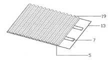
図2A及び2Bは、高温食品を担持する図9〜図13に示したカートン3等のボックスに使用する通気ボックスのパネル2の上面斜視図及び底面斜視図である。パネル2は、3層体すなわち外層体11と内層体13と波形層体19とで出来た三重単層波形ボックスで作成してある。波形層体は、外層体11と内層体13との間に横たわっている。パネル2内の通気通路9は、外側窓孔5と内側窓孔7と二つの窓孔5,7を相互接続する波形の谷部分とを備え、これらが通気通路として機能する。断熱通路9’は、内側窓孔7と、波形の山部分とを備え、断熱通路9’に沿って、及び、断熱通路9’の中に流体を保持する通路として機能する。外側窓孔5は、図9〜図13に示す如くカートン3の外面を画成する外層体11内に配置した窓孔により画成してある。同様に、内側窓孔7は図9〜図13に示す如くカートン3の内面を画成する層体内に配置した窓孔により画成してある。図2A中、内側窓孔7もまた波形層体19を貫通するが、外側窓孔5は貫通していない。図2Aから判るように、窓孔5,7は整列させずに段違いにしてあり、かくして窓孔5,7は実質重複せず、しかもそれらが互いに隣接するようにしてある。
【0081】
通気ボードは、カートン3の蓋15或いは頂部パネル内に配置してある(図9〜図13に図示)。しかしながら、通気ボードはボックスのどのパネル内にも配置することができる。事実、通気ボードはカートン3の基部パネル17と蓋パネル15の両方に配置することができる。
【0082】
この好適な実施形態において、カートンの作成に使用する材料は多重単層板紙であり、それは少なくとも一つの波形層体を有する。図2A中、図示の実施形態は三重単層、すなわち一つの波形が通気通路9及び断熱通路9’を構成する波形層体19及びカートン3の外層体11と内層体13をそれぞれ構成する二つの薄板層体(図9〜図13に図示)を有する。2以上の波形(図示せず)を持たせ、二つの窓孔5,7を結ぶ通気通路9と、窓孔7と繋がる断熱通路9’を画成することが可能である。
【0083】
図9〜図13に示すカートン3は、輸送中の物理的衝撃を介して生じ得る損傷から食品を保護することにより、また食品を断熱することにより、またボックスの内面上に蒸気が結露したり食品から蒸気が放散されるのを阻止することで、食品輸送中に高温の持ち帰り食品を収納することを意図するものである。この種結露は、食品に接触し或いは形成されたときに食品をふやけさせる。かくして、通気ボードの窓孔7をカートン3内の食品の真上に配置した場合に、食品から放散される蒸気が通気ボードを介してカートン3外部の環気へ自由に流れる。蒸気は、食品上方の内層体13の内面に結露はしない。窓孔5,7は整列していないため、カートン3外部から食品上に異物が直接落下し、それによって食品を汚染することはない。さらに、カートン3内部から外部への蒸気の通路は真っすぐではないが、多層体材料の層体11,13間を通過する際に、通気ボードは熱交換器として機能し、カートン3内に熱を溜め込む。これは、通気通路9の長さ、及び窓孔5,7の一方に繋がる断熱通路9’により得られる。これらの断熱通路9’は、窓孔5,7を相互接続してはいない。
【0084】
カートン3の通気度は、通気通路9と通気ボードの構成要素の異なるパラメータ数により可変することができる。これらのパラメータには、窓孔5,7の断面積と、窓孔間のずれと、かくしてまた窓孔5,7を接続する通気通路9の長さと、窓孔の形状と、通路の構造と、パネルの残りの部分に対する各通路の相対方位と、多層体化材料の作成に使用する材料(例えば、紙の種別)と、波形の数と、通気通路の作成に使用する波形の形状と断面寸法と、カートン3内の通気通路(図9〜図13に図示)の数とが含まれる。
【0085】
同様に、カートン3内の通気ボードのパネルがもたらす断熱の程度は、通気ボードの異なるパラメータの数により可変することができる。これらのパラメータには、窓孔5,7の断面積と形状と、各断熱通路9’の形状と構造と長さと、パネルの残りの部分に対する各通路の相対的方位と、各窓孔5,7へ繋がる断熱通路の数と、各断熱通路の作成に使用する波形の断面寸法と、カートン3内の通気通路の数とが含まれる。
【0086】
好適な実施形態はピザボックスであり、それは四角い基部と浅い深さを有する。ボックスの幅は、その高さの何倍かある。この種ボックスでは、ボックス中心からの側面と縁との間の距離はボックスの側面と縁にのみ位置する通気孔がもたらす効果的な通気にとって大きすぎるものとなる。通気ボードはボックスの頂部パネルとして使用し、通気通路をして高温ピザの真上に配置できるようにすることができる。無論、通気ボックスは食品の通気と断熱とが問題となる場合の多くの持ち帰り食品に使用することができる。
【0087】
カートン3は、呼吸のように断熱と通気を必要とする商品に用いることができる。この種非食品商品には、花や果物やサラダ野菜や乳製品を含む家禽及び園芸製品等の農産物を含む。カートン3は通気が必要とされる他の多くの用途、例えば物品や建築用途に使用することもできる。
【0088】
通気ボードのパネルの作成方法の工程が、図2Aに示してある。通気ボード製造方法の第1の工程では、ボードを互いに合体させた二つの層体、例えば一重の単層層体と外層体11と、内層体13と波形層体19を含む二重単層〜多重単層層体とで構成する。通気ボードを作成する上で、薄板面11に固定する一つの波形面19が存在することに留意されたい。これらの面は、完成したボード内の隣接層体となる。そこで、二つの窓孔5,7を各層体内に画成する。これらの窓孔の位置は、波形層体19の面に薄板層体11を固定する際に、互いに対し窓孔を整列させずかつ実質重複させず、通気通路9が波形層体19と薄板単層体11の面間に画成されるよう選択する。好ましくは、窓孔5,7を先ず画成し、続いて形成、好ましくは型抜きする。本方法の第2工程では、隣接層体を互いに固定し、それによって通気ボード内に通気通路9を形成する。
【0089】
図3Aは、三重単層波形ボードで出来た通気ボードのパネル内の通気通路の分解図を示す。A−A線が、外層体内の窓孔5を二分している。B−B線が、内側窓孔7を外側窓孔5へ相互接続する通路9を二分している。C−C線が、内側窓孔7を二分している。X−X線が、内側窓孔7を第2の外側窓孔5へ相互接続する通気通路9及び内側窓孔7に接続する断熱通路9’を二分しており、Y−Y線がパネル内の断熱通路9’を二分している。図3Bは、パネル内の波形において、矢印により示す流体の流れを示すX−X断面とY−Y断面との間のパネルの拡大斜視図である。E−E線(図3Aに示す如く)がX−X断面とY−Y断面に垂直に、波形の谷部分でパネルを二分しており、F−F線がX−X断面とY−Y断面に垂直に、波形の山部分でパネルを二分しており、D−Dがパネルを斜めに二分している。E−E線と同じく、D−D線が層体と流入口と通路を三つ全て二分している。
【0090】
図4Aは、図3Aに示した各A−A,B−B,C−C,D−D,E−E,F−F線に沿うこのボードの一連の断面図を示す。これらの断面図は、通路(9,9’)と外側窓孔5と内側窓孔7に対する矢印にて示す流体の流れを示している。これらの線図は、通気と断熱の本発明と同時に本願明細書に開示した通気ボードの製造方法との教示の例示に役立つものである。
【0091】
通気時に、高温流体は通気ボード内を通って内側窓孔7から通気通路9を介して層体11内の外側窓孔5へ移動し、そこで外気中へ放出される。断面C−Cは、内層体13の内側窓孔7を介して通気通路9及び断熱通路9’の内部へ流入する高温流体を示す。図3Bと図4のB−B断面に示す如く、流体は波形層体19の谷部分と外部薄板単層体11の樋が生み出す通路9に沿って移動する。E−E断面に示す如く、流体は通気通路9を介して外層体11内に画成された外側窓孔5へ移動し、そこでA−A断面に示す如く通気ボードから離脱する。
【0092】
また、E−E断面に示す如く、流体は窓孔5から離れた断熱通路9’に沿って、また、断熱通路9’の中に、ボードの端部へ向かって移動することができる。ボードの端部は、代替開口5’を画成するよう開放させることができる。
【0093】
F−F断面に示す如く、流体は、断熱通路に窓孔7を介して流入し、断熱通路9’に沿って、また、断熱通路9’の中へ移動し、断熱通路9’の中に保持される。
【0094】
断熱体では、高温流体はE−E断面に示す如く内側窓孔7から通気ボードを介して外側窓孔5から遠い断熱通路9’内へ移動し、F−F断面に示す如く断熱通路9’に沿って、また、断熱通路9’の中へ移動する。流体からの熱は雰囲気中へは放出されないが、断熱通路9’内に溜め込まれ、ボード材料の繊維により吸収される。流体が湿っている場合、流体は断熱通路9’内で水として結露する。水は極めて高い比熱量を有するため、断熱通路9’内の水量の増大がそれによってボックスが吸収することのできる熱量を増大させる。因みに、断熱通路9’内に水が溜まった際、それが通気ボード下側に位置する食品や他の品目上に落下することはない。
【0095】
本方法により、断熱通路はボード内側の高温食品をボード他側のより低温流体から断熱するよう機能する。ボードがその波形の開放端部をボードの端部に有するような場合、これらを閉じて閉塞開口5”を提供し、これらの閉じた開口と個々の窓孔5,7との間の通路が断熱通路9’となるようにできる。それ故、封止「断熱通路」9’内に形成された結露が通路内に残留する。ボードを食品保存用ボードの作成に使用した場合、結露水が食品上に落下することはない。熱はボックス内に溜め込まれ、水蒸気の損失は一切ないか或いは殆どない。
【0096】
断熱通路9’は、流体を内側窓孔7から閉塞開口5”或いは図3Aに示す別の内側窓孔へ向けて案内するよう、波形層体19の頂部下側の内層体13間に図3Aと図3Bに示したように画成することができる。さもなくば、それらは断熱通路9’に沿って、また断熱通路9’の中に、内側窓孔7から閉塞開口5”へ向け、外層体と波形層体の樋とが画成する通路に沿って外側窓孔5から遠くへ導くことができる。無論、外側窓孔5が内側窓孔7ではなく波形層体を貫通する場合、この状況は逆転する筈である。内側窓孔7に外側窓孔5を相互接続する通路9が、そこで波形層体19頂部と内層体13の隣接面との間を通過する筈である。
【0097】
通気ボードの好適な製造方法は、分割層体型抜き技法を含む。この分割層体技法では、層体を互いに固定してボードを作成する前にボードの層体を個別に型抜きし、これらの層体を互いに固定したときに隣接層体の窓孔が重複しないようにする。しかしながら、層体間の波形とボードの層体内の波形とが最内層体と最外層体内に位置する窓孔間の間接的通路を生み出す。無論、ボード内の一部の通路は、一旦作成すると、これら二つの窓孔の一方にだけ繋がる。かくして、この技法により作成される構造は断熱特性と通気特性の両方を有する。
【0098】
パネル2の用途に応じ、器具5,7の位置を中心域に調整するか、或いは任意のパターン又は任意の構造を有するパネルを作成するボード全体に分散させるかのいずれかが可能である。
【0099】
図5Aと図5Bと図5Cは、単一の通気通路を二重単層波形ボードで出来たパネル或いは通気ボード内に組み込むことのできる仕方を示すものである。図5Aは、内側窓孔7としてそれぞれ機能する二つのスリットを有する内層体13と各波形の開口端が外側窓孔として機能する波形層体19とを有するパネルを示す。図5Bは、図5Aを裏返した図である。図5Cは、二重単層パネル内の通気手段の代替実施形態を示すものであり、波形層体19だけを裁断して窓孔を持たせてある。本実施形態では、各波形の開放内端が内側窓孔7として機能し、各波形の各外側開口が外側窓孔5として機能する。図5Dは、図5Cに示す実施形態のさらなる変形例を示す。本実施形態では、内層体は内側窓孔を画成する二つの細長い窓孔を有する。図5E(1)と図5E(2)は、パターン化面を達成する非直線型抜きにより作成される通気通路を有する二重単層波形ボードで出来たパネルのさらなる実施形態を示す。図5Dと図5Eに示す二重単層波形ボードは、下側の通気を必要とする品目、例えば食品の下側に配置してそれをふやけさせないようにする通気手段を有するマットとして、それぞれ使用することもできる。
【0100】
図6Aと図6Bは、通気ボードの製造方法に含まれる工程を例示するものである。図6Aは、例えば三重単層ボード内の外層体11の単一の薄板単層体を薄板単層13と波形単層19とからなる内層体から型抜き分離することを概略示すものである。内層体は薄板単層13と波形単層19を併せ型抜きすることで、一度に型抜きされる。図6Bは、一方の層体内の単層11からなる二つの層体と他方の層体内の波形単層19と第2の単一薄板単層13とを併せ組み立て、通気通路及び断熱通路を有する通気ボードのパネルを形成する仕方を示すものである。
【0101】
図7Aと図7Bは、四重単層以上からなる多重単層層体と少なくとも一つの通気通路を有する波形ボードのパネル内の恐らくは三重層体以上の各種組み合わせと構成を示すものである。これらの図面はまた、ボードの層体の可能な配置を例示し、ボードの残りの部分に対する通路の相対的方位がパネル全体で変化する仕方を示すものである。
【0102】
図7C、図7D、図7E、図7Fは、三重単層以上からなる通気ボード内の通路9の可能な構成の断面を示す。図7Cは、五重単層ではあるが2層体化した通気ボードを示す。二つの窓孔5,7を相互接続する通路9が、一つだけ存在する。図7Dは、五重単層3層体化通気ボードを示す。それは、各通路が通気ボード内の層体の異なる面間にある二つの相互接続通路9を有する。図7Eは、七重単層2層体化通気ボードを示す。それは、一つの相互接続通路しか持たない。図7Fは、窓孔5,7を繋ぐ3本の通路を有する七重単層4層体化通気ボードを示す。
【0103】
3以上の層体を使用する場合、各層体を二重単層以上で構成できる場合、層体内の単層の窓孔を整列させる。隣接層体間の窓孔は整列しておらず、ほぼ実質重複することなく隣接している。これにより、隣接層体間の通路9の形成が可能になる。2以上の通路が存在する場合、内層体と外層体の間の層体は中間層体として知られる。
【0104】
図8Aはボックス作成用にボードを平坦なパック素材とした波形通気ボード内の一連の通気通路の一側を示し、図8Bは他側を示す。ボックス各部は、刻み目付き線により仕切ってある。素材は、刻み目付き線沿いに折り畳んでボックスを形成することができる。
【0105】
図9A〜図9Eは、少なくとも一つの通気手段1を有するカートン3とそのカートン用の平坦なパック素材型板20とを示す。図9A〜図9Eは、三重単層板紙材料からのカートン3とその型板20の製造工程を示す。本方法は、波形面21を有する層体19を、波形とし得るも好適な実施形態では平坦な別の層体11へ固着することに依拠するものである。
【0106】
図9A中、薄板内単層25と波形単層21とを有する二重単層層体25を所定形状に裁断し、内側窓孔7を画成する孔を持たせてある。図9Bは、層体の他側、すなわち二重単層層体25の平坦な薄板単層面を示す。単層外層体27は、二重単層層体25と同寸法に裁断してある。外側窓孔5を画成する孔が、単層外層体から切り出してある。これらの窓孔5は、内側窓孔7とはオフセットさせてある。単層外層体11はそこで、この単層外層体を二重層体の波形面へ糊付けする等して二重単層層体25へ固着する。かくして、窓孔5,7は重複することなく互いの近傍に位置する。平坦なパック素材型板20をカートン3内へ折り畳む際に、通気通路は図9Eに示す如く蓋15内に配置する。
【0107】
本方法は断面が円形の窓孔5,7の作成にのみ使用するだけでなく、図10A〜図10E、図11A〜図11Eに示す如く、窓孔には矩形断面形状或いは他の任意の選択された形状を持たせることができる。これらの図もまた、窓孔5,7が図10Eに示す如く蓋15内だけでなくカートン3の基部17内にも配置できることもまた示している。
【0108】
図10A〜図10Cと図11A〜図11Cは、平坦なパック素材型板20からそれぞれ二つの型のカートン3を製造する工程を示すものである。各素材は図10A,図10Bに示す波形面21と図10C,図11Cに示す薄板面23を有する単層層体27とを有する二重単層層体25から作成してある。窓孔5,7は、先ずそれぞれ二つの層体27,25へ型抜きする。薄板面23と波形面21をそこで互いに固定し、素材20を形成する。この素材は、続いて図10Eに示す如くカートン3の形に作成することができる。
【0109】
通気通路が蓋15と基部17の両方にあるカートン3をそれぞれ示す図10D、図10E、図11D、図11Eを特に参照するに、カートンは前記通気通路を有する通気ボードで出来た通気マット(図示せず)を基部17上に配置することで、改善されたピザ用途向けに改変することができる。通気通路を配置した基部17の領域上方にこのマットを配置すると、カートン3内の流体循環が改善される。その結果、食品からの蒸気の大半がカートン3外部の外気へ放出され、食品上へ落下する結露水をさらに低減する。
【0110】
様々な内蔵手段を介してボックスの基底部を持ち上げることは、蒸気もまた基部から放出されることを意味する。この種内蔵機構は、ボックス輸送中にボックスに対し畳み込むか折り畳むことができる折り畳み可能な支持体である。ボックスを面上に配置すると、支持体を伸ばして支持体によりボックスを面上に係止するようにできる。続いてボックスを面上に持ち上げ、基部を含む通気ボード内の通気通路を介して流体を通過させ、それによって基部を介してボックスを通気する。この支持体は、無論1以上の脚部とすることができる。
【0111】
好適な実施形態の改変では、波形は正弦波状断面形状を持たせる必要はないが、異なる断面形状を持たせることができる。かくして、この層体には一連の反復する規則的な或いは不規則な断面形状を有する波形を持たせ得る。紙の種別や組み合わせや重ね合わせをそれぞれ可変し、異なる審美的或いは機能的効果(例えば、通気範囲)を達成することができる。これらの改変は、カートン3の最終用途とその設計と意図した外観とに依存する筈である。
【0112】
さらなる改変例では、通気通路はカートン3のパネル内に、カートン3の外層体11と内層体13との間だけでなくカートンを複数の隔室(図示せず)に分割する仕切り壁にも配置し得る。
【0113】
さらなる改変例では、波形が内側窓孔7を外側窓孔5へ繋がっていない場合に断熱通路9’を作成することができる。この種通路9は、波形の少なくとも一部(図示せず)を平坦化して作成される。これは、断熱通路9’と閉塞流出口5”を形成する適切な方法である。
【0114】
主実施形態に起債したカートン等のボックスの作成に用いるパネルが、(非限定一覧において)異種の白色クラフト紙(二重ボード、積層紙、コート紙、バター紙等)、異種プラスチック(高密度ポリエチレン、低密度ポリエチレン、ポリエチレン、ポリプロピレン、ポリスチレン、ポリカーボネート等)、PET(ポリエチレンテレフタレート)、PVC(ポリ塩化ビニール)、ガラス、繊維、ガラス繊維、ゴム、材木、パーティクルボード、合板、木、薄板、単板、トタンやアルミニウムや合金を含む金属シート、セラミック、セメント、粘土、土類、土壌、アスベストシート、素線又は金網からなるシート、織布又は不織布、或いはこれらの材料の組み合わせを含む板紙以外の各種原材料で作成できることを意図するものである。通気ボードの単層を構築する層体は、各種組み合わせにおいて同一材料又は異なる材料とすることができる。
【0115】
さらなる実施形態では、通路は二つの波形層体を合わせ固定することで形成することができる。それらは、それらの波形を互いに平行或いは垂直とする必要はないが、これらは好適な実施形態である。波形の幅と形状は同じにする必要はないが、これらの特徴もまた好ましいものである。
【0116】
さらなる改変例では、通気ボードには窓孔5,7の一方しか形成されていない断熱体しか配設しない。通路9は形成された窓孔に接続してあり、それによって通気機能は伴わないが本願明細書に説明した如くボードを断熱体として機能できるようにする。
【0117】
本発明により作成したボックスのさらなる実施形態が、図12に示してある。それは、通気通路の外側窓孔5の形状がレタリングで出来ている点を除き、図9、図10、図11に示したボックスに非常に似たものである。
【0118】
図10,図11,図12に示したボックスは、いずれも改変して図13に示す如くボックスの内面の底部で内側窓孔7上方に多重単層(例えば、二重単層)波形通気ボードを配置することで、高温食料との使用に向け改善するよう改変することができる。前記通気通路を有するこの種装具はボックス内の流体循環を改善し、ボックス内に熱を溜め込み、蒸気や水がボックス外部へ放散できるようにする。
【0119】
このマットは、包装に使用する装具或いは物品の一種である。ボックス用のこの種装具には、区画用間仕切り或いは区画壁もまた含まれる。
【0120】
好適な実施形態において、通気ボードから作成されるボックスの実施形態は、電子レンジ等のオーブンや冷凍庫での使用に合わせた寸法とすることができる。これらの実施形態は、これらの用途に適した材料、好ましくは厚紙から作成することができる。
【0121】
通気ボードから作成したボックスの一部実施形態では、窓孔を配置した通路と層体は、組み合わせにおいて互いに関連して本願明細書に記載した通気ボードと同じ仕方で機能する通気システムを提供する異なる要素から作成し得る。例えば、通路はそれぞれシリンダの異なる端部に隣接配置される窓孔を有する二つの層体間に横たわる端部開口シリンダともし得る。シリンダを層体に固定しない場合、この構成はシステムであって、通気ボードではなくなる。同じ構成が、本願明細書に記載した通気ボードとしての利点を達成する。
【0122】
本願明細書に記載した実施形態は、本発明の好適な実施形態の実例とすることのみを意図するものである。本説明は、本願明細書に記載した実施形態と同じ結果を有する全ての変形例と適用例とを組み込むよう意図するものである。
【図面の簡単な説明】
【0125】
【図1】従来の波形ボードを示す一連の概略図であり、図1Aは二重単層波形ボードを表す図であり、図1Bは三重単層波形ボードを表す図であり、図1Cは従来の直接通気貫通孔付き三重単層波形ボードを表す図である。
【図2】本発明になる通気ボードで出来たボックスのパネル内の通気通路を示す一連の概略図であり、図2Aは、本発明による通気ボードのパネルの上面斜視図であり、図2Bは、図2Aに示される通気ボードのパネルの底面斜視図である。
【図3】本発明になる波形ボードで出来た三重単層通気ボックス内の通気通路を示す一連の2個の線図(3A,3B)である。
【図4】本発明になる三重単層波形ボード内の通気通路の断面を示す一連の6個の線図(4A〜4F)である。
【図5】一連の6個の線図で、うち3個(5A〜5C)が本発明になる通気ボードを作成する二重単層層体で、各層体が連続層体の一つに少なくとも一つの切除部を有する層体を示し、うち3個(5D,5E1,5E2)が各単層層体が少なくとも一つの窓孔を有する二重単層波形ボードを示す図である。
【図6】通気通路及び断熱通路を有する本発明になる通気ボードの三重単層パネルの製法を示す一連の2個の概略線図(6A,6B)である。
【図7】一連の6個の線図であり、うち2個(7A,7B)が本発明になる多重単層層体通気ボードにおける単層の各種構成を示す線図であり、うち4個(7C,7D,7E,7F)がボード内の単層の具体的構造における幾つかの層体を示す通気ボードの可能な組み合わせの断面図である。
【図8】通気通路を備える本発明になる波形通気ボードで出来たボックス用の素材を示す一連の2個の概略線図である。
【図9】製造中に複数の通気通路がその蓋の中にある状態の本発明になる通気ボードで出来たボックスを示す一連の5個の概略図であり、図9(A)は上方を向く波形を有する二重単層型抜き波形層体を示す図であり、図9(B)は波形が下方を向く状態で図9Aに示した二重単層型抜き波形層体を示す図であり、図9(C)は型抜き薄板層体を示す図であり、図9(D)はボックスの蓋を開蓋し、ボックスの逆側パネルに平行にした状態で図9A、図9B、図9Cに示した二重単層層体の波形面へ薄板層体を固定して作成したボックスを示す図であり、図9(E)はその蓋を閉じた状態の図9Dのボックスを示す図である。
【図10】ボックスがその蓋とその基部に複数の簡単な通気通路を備える状態で、製造中の本発明になるボックスを示す一連の5個の概略図であり、図10(A)は上方を向く波形を有する二重単層抜き波形層体を示す図であり、図10(B)は下方を向く波形を有する図10Aの二重単層型抜き波形層体を示す図であり、図10(C)は型抜き薄板層体を示す図であり、図10(D)はボックスの蓋を開蓋しボックスの逆側パネルに平行とした状態で図10A、図10B、図10Cに示した二重単層波形面に対し薄板層体を固定することで作成したボックスを示す図であり、図10(E)はその蓋を閉じた状態の図10のボックスを示す図である。
【図11】製造中にその蓋とその基部に複数のパターン化通気通路を備える状態で通気ボードで出来たボックスを示す本発明になる5個の一連の概略図であり、図11(A)は上方を向く波形を備える波形面付きの二重単層型抜き層体を示す図であり、図11(B)は下方を向く波形を有する図11Aの二重単層型抜き層体を示す図であり、図11(C)は型抜きした単一の単層平面薄板層体を示す図であり、図11(D)はボックスの蓋を開蓋しボックスの逆側に平行とした状態で図11A、図11B、図11Cに示した二重単層層体の波形面に薄板層体を固定することで作成したボックスを示す図であり、図11(E)はその蓋を閉じた状態の図11Dのボックスを示す図である。
【図12】図11に示したのと同様の本発明になるボックスを示す一連の4個の図(12A〜12D)であり、製造中にその蓋の中に複数のパターン化通気通路を有する図である。
【図13】本発明になるボックスの基部に横たわる通気マットを有する図10に示したボックスを示すものであり、通気マットが通気ボードで出来ていて通気通路を有する図である。
【符号の説明】
【0126】
5 第1の窓孔
7 第2の窓孔
9 通路
11 層体
13 隣接層体
【Technical field】
[0001]
The present invention relates to a vent board for use in various applications including fast food packaging, particularly take-away pizza packaging, a box containing a panel made of this board, a vent system, and a vent board manufacturing method.
[Background]
[0002]
The panels used to create boxes, drums, cans, containers, cases, pallets, wooden frames, shipping containers, etc. need to be ventilated. Many of these applications are used for storage purposes, in which case ventilation and / or insulation are generally important considerations. Both of these considerations are important for fast food packaging design.
[0003]
Fast food packaging has three purposes. A packaging material such as a carton or other type of box must retain the heat of the food it contains, which must not cause the food to swell as a result of steam condensing into water on the inner surface of the carton; and Since packaging is usually disposable, it must be cost effective.
[0004]
In general, currently widely used packaging materials achieve the final purpose in conjunction with only one of the first two purposes. It has been difficult to create packaging materials that meet all three objectives simultaneously.
[0005]
Known packaging materials do not meet all three objectives due in part to the following reasons. When the packaging material and the food in the packaging material are transported, heat from the food and the packaging material is dissipated, and steam is released into the atmosphere in the packaging material. The packaging material is colder than the food. As the heated steam from the food rises vertically above the food, it rises toward the packaging lid or cover. When in contact with the lid, the vapor condenses on the water on the lid and transfers heat to the packaging. The condensed water then falls freely onto the food, making it soft and dropping its taste.
[0006]
Cartons made of expanded polystyrene try to overcome this problem by retaining heat in the carton because it is a strong thermal insulation material. However, as time elapses, heat again escapes from the carton, thus forming condensation in the carton above the food.
[0007]
Another well-known carton is made of corrugated paperboard. Corrugated paperboard is used to create cartons because of the inherent properties of its corrugated structure. The original corrugated structure provides resistance and dispersion against forces applied parallel or perpendicular to the corrugated structure's waveform. When a force is applied in the direction of the corrugated flutes, the flutes are compressed and function like struts, thereby resisting the compressive force. The corrugated structure then improves the compressive strength of the board. When a force is applied perpendicular to the direction of the flutes of the corrugated structure, the flutes deform, absorb the energy of the impact force and disperse the forces through the board. Thus, the corrugated structure improves the strength of the board by providing resistance to the applied force.
[0008]
When a multilayer corrugated board is used, the board layers are generally used with their flutes parallel to the flutes of adjacent layers. Thus, multilayer boards can withstand compressive forces and forces that would normally deform the flutes. In these environments, the board remains robust. Food in cartons typically made of triple monolayer or quintuple monolayer paperboard is protected from physical irritation during transport. Moreover, even with these advantages, condensation may form on the inner surface of the carton, causing the food to swell during delivery.
[0009]
Therefore, as these known carton types show, in the fast food industry, especially those stores that sell pizza, high temperature food products that do not cause unnecessary water condensation inside the carton, especially under the lid. There is a need for packaging materials that do not allow heat to escape.
[0010]
Developments have been made to allow partial discharge of this kind of carton steam. One such development is the placement of holes or slits near the sides or edges of the carton. However, for products such as pizza, the heated air and steam from the center of the pizza cool the steam well before the air and steam reach the hole, and water forms on the lower surface of the lid above the food. Let The holes and slits in the carton are not located directly above the food, which quickly removes the vapor from the carton. The location of the holes above the food may cause foreign objects and contaminants to fall onto the food. Furthermore, the use of this type of direct hole through the board panel reduces the strength of the board.
DISCLOSURE OF THE INVENTION
[Problems to be solved by the invention]
[0011]
The object of the present invention is to provide a ventilation board and a ventilation system that meet the above-mentioned three purposes exemplified by the drawbacks of known food packaging materials when used to make panels that define sealed spaces such as cartons. There is. That is, providing sufficient ventilation of the carton so that water condensed from the vapor of the food does not flow onto the food in the carton, and provides sufficient heat insulation so that the food in the carton is kept warm.
[0012]
A further object of the present invention is to provide a box made of this ventilation board, a flat pack material to be produced in this kind of box, and a method for manufacturing the ventilation box.
[Means for Solving the Problems]
[0013]
According to the first aspect of the present invention, there is a ventilation board made of a multilayer material, and the board has a layer body provided with a first window hole and an adjacent layer provided with a second window hole. Interconnecting the first and second window holes, wherein the adjacent layer bodies are arranged relative to each other so that the first window holes and the second window holes are not aligned and do not substantially overlap. whileAnd the ventilation boardFluid flow ofVentilationAisle andThe heat insulating passage connected to one of the window holes, the heat insulating passage providing heat insulation by allowing fluid to flow along the heat insulating passage and inflow of fluid into the heat insulating passage;Is provided.
[0014]
Conveniently, the vent board has improved venting means because it allows air-containing fluids to pass through the board but not through it.
[0015]
Preferably, the window holes are adjacent to each other.
[0016]
Have at least one corrugated surface at the boundary between a layered body and an adjacent layered body, so that at least one of the corrugations in the surface depends on its inherent shape and structureVentilation passage and heat insulation passageCan be defined. The advantages of this configuration of layers or parts of layers in the ventilation board include its high strength capability and its shock absorption capability, and each corrugation in the board provides off-the-shelf components for creating a passage. To do. Conveniently, these features can be derived from the unique shape and structure of each waveform.
[0017]
At least one of the window holes is preferably defined by a first edge and a second edge, wherein the first edge is a part of the peripheral edge of the surface of the layer defining the window hole, and the second edge Is part of the edge of the adjacent surface, thereby defining the open end of the corrugation. Conveniently, one of the window holes is formed on the edge of the board using the intact structure of the surface between the two layer bodies and the edges of these surfaces close to the periphery thereof to form this window hole.
[0018]
The boundary between the layer body and the adjacent layer body can be constituted by a thin layer surface.
[0019]
A vent board is a plurality of generally parallel layers including a layer body, an adjacent layer body, and one or more additional layer bodies, each adjacent at least one other layer body, each additional layer body having a window. The plurality of layer bodies, wherein holes are disposed, relative to the window holes in the layers adjacent to each further layer body, so that the two window holes are not aligned and do not substantially overlap; Further interconnecting the two window holes to allow fluid flow between them and through the ventilation boardVentilationAnd a passage. Conveniently, the board can be of greater strength because it consists of two or more layers, thus the board has at least one intermediate layer.
[0020]
In the second aspect of the present invention, a plurality of substantially parallel layer bodies, each layer body adjacent to at least one of the other layer bodies, each layer body relative to a window hole in the layer body adjacent to the layer body. The plurality of layered bodies provided with the arranged window holes so that these two window holes are not aligned and do not substantially overlap with each other, and the window holes are interconnected so that fluid can flow between them and through the ventilation board DoVentilationThere is a vent board with a passage. Conveniently, the board can be of greater strength because it consists of two or more layers and thus the board has at least one intermediate layer.
[0021]
Preferably, the board has an air permeability through the board.VentilationDepending on the physical dimensions and / or shape of each of the passages and the first and second window holes, the air permeability can be varied to suit the intended use of the board. Conveniently, the air permeability can be changed by varying these parameters to suit the intended function of the board.
[0022]
Board has air permeability and window holesVentilationIt can depend on the cross-sectional area of at least one of the passages.
[0023]
The board can be such that the air permeability depends on the deviation between the first window hole and the second window hole.
[0024]
Board has air permeability and window holesVentilationIt can depend on the cross-sectional shape of at least one of the passages.
[0025]
Board has air permeabilityVentilationIt can be made dependent on the structure of the passage.
[0026]
The board has air permeability to the rest of the boardVentilationIt can be made dependent on the relative orientation of the passages.
[0027]
The board may be such that the degree of insulation provided by the board depends on the physical dimensions and / or shape of the insulated passages and / or the window holes connecting the passages. Conveniently, the degree of thermal insulation provided by the board can be varied to suit the board application.
[0028]
Preferably, the heat insulating passage is at least one passage. Conveniently, the board can have more than one insulated passage, and the connection window holes can be connected to more than one insulated passage.
[0029]
At least one of the layer body and the adjacent layer body may be a single layer.
[0030]
At least one of the layer body and the adjacent layer body may be a multiple single layer body, wherein the window holes in each multiple single layer layer are formed by the window holes in each single layer in the layer body, All window holes in the monolayer of the layered body are substantially aligned.
[0031]
Preferably, the window holes are connected by at least one passage.
[0032]
Each of the first window hole and the second window hole includes at least one window hole. Conveniently, each of these window holes may be a single window hole or each may be two or more window holes.
[0033]
The passage is preferably at least one passage. Conveniently, each passage is a singleaisleAlternatively, a plurality of passages can be provided.
[0034]
Ventilation board, ventilation box and ventilation system are paper, paperboard, white paper, kraft paper, double board, laminated paper, coated paper, butter paper, plastic material, high density polyethylene, low density polyethylene, polyethylene, polypropylene, polystyrene, Includes polycarbonate, PET (polyethylene terephthalate), PVC (polyvinyl chloride), glass, fiber, glass fiber, rubber, wood, timber, particle board, plywood, wood, thin plate, veneer, metal sheet, tin, aluminum, and alloys Made of at least one material including, but not limited to, metals, ceramic materials, cement, clay, earth, soil, asbestos sheets, wire or wire mesh sheets, woven or non-woven fabrics, synthetic materials, combinations of the above materials be able to. Conveniently, the board is made of a single material or a combination of materials. Preferably, the board is made of paperboard. This material is conveniently adapted to items such as disposable packaging due to its light weight and low cost.
[0035]
Preferably, the board is configured for use in a microwave oven, a refrigerator, or both.
[0036]
In a third aspect of the present invention there is a box having a panel comprising a vent board according to the first aspect of the present invention. Conveniently, the board provides improved ventilation within the box, which can insulate the box to maintain a temperature differential inside and outside the box, making the board a useful material for fast food packaging. The box accumulates heat in the box, vents the box, and prevents hot food in the box from spreading.
[0037]
Preferably, the panel constitutes the box top. Conveniently, the steam in the box can be released directly into the atmosphere from inside the box, even from a window hole located directly above the hot food in the box, and something falls from above through the ventilation board. There is little risk of contaminating food.
[0038]
This panel can constitute the bottom of the box. This advantageously improves fluid circulation within the box and thus also improves the ventilation of the box. Furthermore, the steam from the high temperature food can be released from the bottom of the high temperature food to the outside of the box without risk of the food falling outside the box.
[0039]
The box further comprises a foldable support disposed or positioned on the base, wherein the support is a first position for transporting the box, wherein the support is folded in or against the plane of the box. And a second position for supporting the box above the surface, extending the support and lifting the base above the surface, thereby improving the ventilation of the box through the ventilation board in the base. Have. Preferably, the support includes a plurality of legs.
[0040]
The panel preferably constitutes the side wall of the box. Conveniently, this allows ventilation of the box through the side panels of the box, which is particularly useful for stacked boxes.
[0041]
This box can have an appliance made of a panel of the ventilation box according to the first aspect of the present invention.
[0042]
The brace can be a partition, which allows ventilation between the partitions in the box.
[0043]
Otherwise, the brace can be a mat that is placed on the box base within the box.
[0044]
In the fourth aspect of the invention, there is a flat pack material that folds into the box according to the second aspect of the invention.
[0045]
In a fifth aspect of the invention there is an appliance that fits into a box and wraps an article that requires ventilation, the appliance comprising a ventilation board according to the first aspect of the invention.
[0046]
Preferably, the brace is a mat that supports an article that requires ventilation below its lower surface. Conveniently, fluid can be vented through the base when the mat is locked onto the aeration board in the base and the food is locked onto the mat. This fluid circulation in the box is thereby further improved and further prevents the food from spreading.
[0047]
In the sixth aspect of the present invention, the ventilation board of the first aspect of the present invention is not limited to these, but roofs, partitions, doors, door panels, window panels, outer walls, flooring, darkrooms, shops It is configured to be used for architectural purposes including Architectural applications include the placement of buildings and awning walls that allow ventilation through the sides of the building and awning.
[0048]
In the seventh aspect of the present invention, the ventilation board according to the first aspect of the present invention is not limited thereto, but includes a bag, a cover, a paper pouch, a paper tool, a pot, a vase, a bucket, a coaster, a wrapping paper, and a lid. It is configured to be used for articles including baggage members, shoes, shoe soles, hats, helmets and the like.
[0049]
In an eighth aspect of the present invention,There is a ventilation system, this ventilation systemA first window hole in a layer body and a second window hole in an adjacent layer body, wherein the first and second window holes are relatively aligned so as not to align and substantially overlap; Interconnect the two window holes, therebyAnd ventilation systemFluid flow ofVentilationA passage,A heat insulating passage connected to one of the window holes, a heat insulating passage that provides heat insulation by allowing fluid to flow along the heat insulating passage and allowing the fluid to flow into the heat insulating passage;Is provided. Conveniently, the present invention can be achieved using a collection of correlation components.
[0050]
In a ninth aspect of the present invention, there is a method for manufacturing a ventilation board, and the ventilation board has at least two adjacent layer bodies, each having a surface that abuts each other, and at least one corrugated adjacent surface. The method comprising a layered body, the step of arranging a window hole in each layered body;A ventilation passage is formed between the surfaces of the adjacent layer bodies, and window holes are interconnected to allow fluid flow between the two and the board, so that the window holes of the adjacent layer bodies are not aligned and do not substantially overlap. Forming a heat insulating passage by fixing the layer bodies to each other, allowing the flow of fluid along the heat insulating passage and the inflow of fluid into the heat insulating passage;including.
[0051]
The step of arranging the window holes in each of the first and second layer bodies includes (1) a step of defining window holes in each layer body, and (2) a step of forming window holes in each layer body. Can be included.
[0052]
The step of forming the window hole in each layer can include a step of punching the layer.
[0053]
The method can further include selecting a ventilation range provided by the ventilation board.
[0054]
The step of selecting the ventilation range can include selection of the cross-sectional area of the window holes in each layer.
[0055]
The selection process of the ventilation range may include selection of a shift between the window holes of the adjacent layer body or between both of them including both ends.
[0056]
The selection process of the ventilation range may include selection of the passage structure.
[0057]
The ventilation range selection step may include selection of the relative orientation of the passage relative to the rest of the board.
[0058]
The step of arranging the window holes in each layer and fixing the layers to each other further arranges the window holes in the layers when fixing the adjacent layers, so that a heat insulating passage is defined between the surfaces of the adjacent layers. The insulating passage may connect the one of the window holes, thereby allowing the fluid to flow along the insulating passage through the connection window hole. Conveniently, when there is a temperature difference between a layered body and an adjacent layered body, the flow of fluid through the connection window hole along the passage provides thermal insulation properties to the vent board.
[0059]
According to a tenth aspect of the present invention, there is a method for manufacturing a box having a side surface comprising a ventilation board according to the first aspect of the present invention.
[0060]
In an eleventh aspect of the present invention, the heat insulating board is a heat insulating board made of a multilayer material, and is connected to the layer body disposed in the window hole, the adjacent layer body, and the window hole. There is a thermal insulation board with a thermal insulation passage that allows fluid to flow through the window hole along the passage. Conveniently, when there is a temperature difference between a layer body and an adjacent layer body, the flow of fluid along the passageway and through the connecting window hole provides a heat insulating property to the heat insulating board. Conveniently, the board also functions as a thermal insulator, maintaining a temperature difference between the two layers, ie on both sides of the board.
[0061]
(Definition)
In this specification, the term “carton” is used interchangeably with the term “box” and it should be understood that a box has a broader meaning than a carton. Further, the term box is used herein to mean any of drums, cans, containers, cases, pallets, wooden frames, transport containers, and other storage devices.
[0062]
“Appliance” is a device used for a packaging material suitable for fitting into a box.
[0063]
A “panel” is a part of a ventilation board that creates the surface of an article made of, for example, a ventilation board, for example a box.
[0064]
A “monolayer” is a single sheet material. It can be a thin plate or corrugated. As a thin sheet, it can refer to a top backing or a back backing. A corrugated monolayer is also known as a corrugated backing or corrugated medium.
[0065]
The “layer body” is composed of at least one single layer, and thus the layer body can be a multiple single layer. The layered body may be a single corrugated single layer or thin plate single layer, a plurality of such single layers, or a combination of both, to form a multiple single layer layer. In the multi-layer structure of the ventilation board, all the window holes are aligned. The layered body has two surfaces. Adjacent layer bodies have at least one corrugated surface at their boundaries (ie, when they abut).
[0066]
A “multilayer body” is a board composed of a plurality of layer bodies, ie it is a multilayer material.
[0067]
“Fluid” includes gases and liquids, thus vapor, vaporized gas and air.
[0068]
"VentilationA passageway interconnects window holes in different layers, andAnd in the ventilation boardAllows fluid flow and allows the board to vent the sealed space.
[0069]
A “duct” or ventilation duct is a type of passage. The passage connects the two window holes on each side of the board.
[0070]
"Insulated passage"On one side of the ventilation boardConnect the window holesThe passage, Allowing fluid to pass through the window holes along the insulated passageAnd prevent fluid from passing through the board.
[0071]
The “configuration” of the passage refers to the dimension of the passage and the shape of the passage.
[0072]
The “orientation” of the passage refers to the direction the passage has relative to other passages in the layer or in the board in which the passage is located. Therefore, the relative orientation of the passages in the board refers not only to the relative configuration they have to each other, but also to the combination of directions that the passages have in the board.
[0073]
“Architecture use” includes roofs, partitions, doors, door panels, window panels, outer walls, darkrooms, stores, etc. in the delinquent limited list.
[0074]
“Articles” include bags, covers, paper pouches, paper utensils, pots, vases, buckets, coasters, lids, luggage components, shoe soles, shoes, hats, helmets, microwave ovens, refrigerators, etc. It is an item made of air vent board. In general, these items are in fields other than packaging and building applications.
[0075]
“Substantial” refers to a feature within the scope of the claims to which the term “substantial” refers to a feature that will not affect how the invention functions in the light of the skilled artisan reading the specification. Refers to minor deformations.
[0076]
A “system” is a group or combination of mutually related elements, independent elements, or interacting elements that form a collective entity.
[0077]
The terms “first” and “second” are used in the claims to differentiate between two window holes. The term “adjacent” is also used for layer differentiation. These terms do not imply any property that the window or layer body owns or does not own. The specification will use more appropriate terms that are better suited to the preferred embodiments of the invention described herein. This kind of term includes inside and outside because these terms mean direction. They are better suited to the description of the board used in the box, for example.
BEST MODE FOR CARRYING OUT THE INVENTION
[0078]
A ventilation board, a box including the ventilation board, a flat pack material folded in the box made of the ventilation board, a ventilation system made of the ventilation board, and a manufacturing method of the ventilation board, with reference to the accompanying drawings, by way of example This will be explained here.
[0079]
Referring to the drawings, taking a typical structure of a corrugated board as an example, FIG. 1A shows a corrugated board made of double single layers having an
[0080]
2AAnd 2BIs a
[0081]
The ventilation board is arranged in the
[0082]
In this preferred embodiment, the material used to make the carton is a multi-layer board, which has at least one corrugated layer. In FIG. 2A, the illustrated embodiment is a triple monolayer, ie, one waveformVentilationPassage 9And heat insulating passage 9 'And two thin plate layers (illustrated in FIGS. 9 to 13) constituting the
[0083]
The
[0084]
The air permeability of
[0085]
Similarly, the degree of thermal insulation provided by the panels of the ventilation board in the
[0086]
A preferred embodiment is a pizza box, which has a square base and a shallow depth. The width of the box is several times its height. In this type of box, the distance between the side and the edge from the box center is too large for effective ventilation provided by vents located only on the side and edge of the box. The ventilation board is used as the top panel of the box, and the ventilationaisleCan be placed directly above the hot pizza. Of course, aeration boxes can be used for many takeaway foods where food ventilation and insulation are a problem.
[0087]
The
[0088]
The steps of the method for making the vent board panel are shown in FIG. 2A. In the first step of the ventilation board manufacturing method, two single layers including a single single layer layer and an
[0089]
Figure 3A shows the ventilation in the panel of a ventilation board made of triple single layer corrugated board.aisleAn exploded view of is shown. The AA line bisects the
[0090]
4A shows each of AA, BB, CC, DD, and EE shown in FIG. 3A., FFA series of cross-sectional views of this board along the line is shown. These cross-sections show the passage(9, 9 ')The flow of the fluid shown by the arrows with respect to the
[0091]
When ventilating, hot fluid is in the ventilation boardThroughFrom the inner window hole 7VentilationIt moves to the
[0092]
Moreover, as shown in the EE cross section, the fluid is separated from the window hole 5.Along the insulating passage 9 'and in the insulating passage 9',It can move towards the end of the board. The end of the board can be opened to define an alternative opening 5 '.
[0093]
As shown in the FF cross section, the fluid flows into the heat insulating passage through the
[0094]
In the heat insulating body, as shown in the EE cross section, the high-temperature fluid passes from the
[0095]
With this method, the insulated passage functions to insulate the hot food inside the board from the colder fluid on the other side of the board. If the board has its corrugated open end at the end of the board, they are closed to provide
[0096]
Insulated passage9 '3A and 3B between the
[0097]
A suitable method for manufacturing the vent board includes a split layer die cutting technique. In this split layer technique, the layers are joined together.FixedBefore creating a board, the board layers are individually die-cut and the layers are joined together.FixedSometimes window holes in adjacent layers are not overlapped. However, the corrugations between the layers and the corrugations in the board layers create indirect passages between the window holes located in the innermost and outermost layers. Of course, some passages in the board, once created, connect only to one of these two window holes. Thus, the structure created by this technique has both thermal insulation and ventilation characteristics.
[0098]
Depending on the application of the
[0099]
5A, 5B and 5C show a single ventaisleShows how it can be incorporated into a panel made of a double single layer corrugated board or a ventilation board. FIG. 5A shows a panel having an
[0100]
FIG. 6A and FIG. 6B illustrate the steps included in the method for manufacturing a vent board. FIG. 6A schematically shows that, for example, a single thin plate single layer of the
[0101]
FIG. 7A and FIG. 7B show a multi-single layered body composed of four or more single layers and at least one ventilationaisleIn the corrugated board panel with the, the various combinations and configurations, perhaps more than triple layers, are shown. These drawings also illustrate possible arrangements of the board layers and show how the relative orientation of the passage relative to the rest of the board varies across the panel.
[0102]
FIGS. 7C, 7D, 7E, and 7F show cross-sections of possible configurations of the
[0103]
When three or more layer bodies are used, when each layer body can be composed of two or more single layers, the single layer window holes in the layer body are aligned. The window holes between adjacent layer bodies are not aligned and are adjacent without substantially overlapping. Thereby, formation of the channel |
[0104]
Figure 8A shows a series of vents in a corrugated board with a flat pack material used to make a box.aisleFIG. 8B shows the other side. Each part of the box is partitioned by a scored line. The material can be folded along a scored line to form a box.
[0105]
9A to 9E show a
[0106]
In FIG. 9A, a single layer in a thin plate25And corrugated single layer21Are cut into a predetermined shape, and a hole for defining the
[0107]
This method is not only used to create
[0108]
FIGS. 10A to 10C and FIGS. 11A to 11C show a process of manufacturing two types of
[0109]
VentilationaisleReferring specifically to FIGS. 10D, 10E, 11D, and 11E, respectively, showing the
[0110]
Lifting the base of the box through various built-in means that vapor is also released from the base. This kind of built-in mechanism is a foldable support that can be folded or folded into the box during box shipping. When the box is placed on the surface, the support can be extended and the box can be locked on the surface by the support. Then lift the box over the surface and vent in the ventilation board including the baseaisleThrough the fluid, thereby venting the box through the base. This support can of course be one or more legs.
[0111]
In a modification of the preferred embodiment, the waveform need not have a sinusoidal cross-sectional shape, but can have a different cross-sectional shape. Thus, the layered body can have a corrugation having a series of repeating regular or irregular cross-sectional shapes. The paper types, combinations, and overlays can be varied to achieve different aesthetic or functional effects (for example, a ventilation range). These modifications should depend on the end use of the
[0112]
In a further modification, ventilationaisleCan be arranged in the panel of the
[0113]
In a further modification, if the corrugation does not connect the
[0114]
Panels used to create boxes such as cartons that are issued in the main embodiment are different white kraft paper (double board, laminated paper, coated paper, butter paper, etc.), plastic (high density polyethylene). , Low density polyethylene, polyethylene, polypropylene, polystyrene, polycarbonate, etc.), PET (polyethylene terephthalate), PVC (polyvinyl chloride), glass, fiber, glass fiber, rubber, timber, particle board, plywood, wood, thin plate, veneer , Metal sheets containing tin, aluminum and alloys, ceramics, cement, clay, earth, soil, asbestos sheets, sheets made of wire or wire mesh, woven fabrics or non-woven fabrics, or various types other than paperboard containing combinations of these materials It is intended to be made from raw materials. The layers that make up the single layer of the vent board can be the same material or different materials in various combinations.
[0115]
In a further embodiment, the passage can be formed by joining and fixing two corrugated layer bodies together. They do not have to have their waveforms parallel or perpendicular to each other, but these are preferred embodiments. Although the corrugation width and shape need not be the same, these features are also preferred.
[0116]
In a further modification, the ventilation board is only provided with a thermal insulator in which only one of the window holes 5, 7 is formed. The
[0117]
A further embodiment of a box made in accordance with the present invention is shown in FIG. It ventsaisleOutsideWindow holeExcept for the fact that the shape of 5 is made by lettering, it is very similar to the box shown in FIGS.
[0118]
Each of the boxes shown in FIGS. 10, 11 and 12 is modified to have a multi-layer (for example, double single-layer) corrugated ventilation board above the
[0119]
This mat is a kind of appliance or article used for packaging. This type of brace for a box also includes a compartment divider or compartment wall.
[0120]
In a preferred embodiment, an embodiment of a box made from a vent board can be sized for use in an oven or freezer such as a microwave oven. These embodiments can be made from materials suitable for these applications, preferably cardboard.
[0121]
In some embodiments of boxes made from vent boards, the passages and layers in which the windows are arranged are different in combination to provide a vent system that functions in the same manner as the vent boards described herein in relation to each other. Can be created from elements. For example, the passage may be an end opening cylinder lying between two layers each having a window hole located adjacent to a different end of the cylinder. If the cylinder is not secured to the layer, this configuration is a system and not a vent board. The same configuration achieves the advantages as the vent board described herein.
[0122]
The embodiments described herein are intended to be examples only of preferred embodiments of the present invention. This description is intended to incorporate all variations and applications that have the same results as the embodiments described herein.
[Brief description of the drawings]
[0125]
FIG. 1 is a series of schematic diagrams showing a conventional corrugated board, FIG. 1A is a diagram representing a double single layer corrugated board, FIG. 1B is a diagram representing a triple single layer corrugated board, and FIG. It is a figure showing the triple single layer corrugated board with a direct ventilation through-hole.
FIG. 2 Ventilation in a panel of a box made of a ventilation board according to the present invention.aisleFIG. 2A is a series of schematic views showingThe top perspective view of the panel of the ventilation board according to the present inventionFigure 2B shows2 is a bottom perspective view of the panel of the ventilation board shown in FIG. 2A.FIG.
FIG. 3 Aeration in a triple single layer ventilation box made of corrugated board according to the present invention.aisleIs a series of two diagrams (3A, 3B) showing
FIG. 4 Ventilation in a triple single layer corrugated board according to the present invention.aisleA series of cross sections showing6Individual diagrams (4A-4)F).
FIG. 5 is a series of 6 diagrams,3Pieces (5A ~ 5C) Is a double monolayer layer body for producing a ventilation board according to the present invention, each layer body showing a layer body having at least one cut portion in one of the continuous layer bodies,3Pieces(5D,5E1 and 5E2) are diagrams showing a double single-layer corrugated board in which each single-layer body has at least one window hole.
[Figure 6] VentilationPassage and heat insulation passageIt is a series of two schematic diagrams (6A, 6B) which show the manufacturing method of the triple single layer panel of the ventilation board which becomes this invention which has this.
FIG. 7 is a series of six diagrams, two of which (7A, 7B) are diagrams showing various configurations of a single layer in a multi-layer laminate board according to the present invention, of which four (7C, 7D, 7E, 7F) is a cross-sectional view of a possible combination of vented boards showing several layers in a single layer specific structure within the board.
[Figure 8] VentilationaisleFIG. 2 is a series of two schematic diagrams showing a material for a box made of a corrugated ventilation board according to the present invention.
FIG. 9: Multiple during manufacturingVentilation passageFIG. 9A is a series of five schematic diagrams showing a box made of a vent board according to the present invention with the inside of its lid, FIG. FIG. 9B is a diagram showing the double single-layer punched corrugated layer body shown in FIG. 9A in a state where the waveform is directed downward, and FIG. 9C is a punched thin plate. FIG. 9D is a diagram showing a layered body, and FIG. 9D is a diagram illustrating a double single layer layered body shown in FIGS. 9A, 9B, and 9C in a state where the box lid is opened and parallel to the opposite panel of the box. FIG. 9E is a diagram showing the box of FIG. 9D with its lid closed, with the thin plate layer body fixed to the corrugated surface of FIG.
FIG. 10: Multiple simple vents on the lid and base of the boxaisleFIG. 10A is a diagram showing a double single-layer corrugated layered body having a waveform facing upward, showing a box according to the present invention being manufactured in a state of being provided with 10 (B) is a view showing the double single-layer punched corrugated layer body of FIG. 10A having a downward-facing waveform, and FIG. 10 (C) is a view showing the punched thin plate layer body. (D) Created by fixing the thin plate layer to the double single layer corrugated surface shown in FIGS. 10A, 10B, and 10C with the box lid open and parallel to the opposite panel of the box. FIG. 10E shows the box of FIG. 10 with its lid closed.
FIG. 11: Multiple patterned vents on its lid and its base during manufactureaisleFIG. 11 (A) is a series of five schematic views according to the present invention showing a box made of a ventilation board in a state of being provided with a corrugated surface. 11 (B) is a diagram showing the double single-layer die-cut layered body of FIG. 11A having a downward-facing waveform, and FIG. 11 (C) is a die-cut single-layer plane. FIG. 11D is a view showing the thin plate layered body, and FIG. 11D shows the double single layered layered body shown in FIG. 11A, FIG. 11B, and FIG. It is a figure which shows the box produced by fixing a thin-plate laminated body to a waveform surface, and FIG.11 (E) is a figure which shows the box of FIG. 11D in the state which closed the lid | cover.
12 is a series of four views (12A-12D) showing a box according to the present invention similar to that shown in FIG. 11, with multiple patterned vents in its lid during manufacture.aisleFIG.
13 shows the box shown in FIG. 10 having a vent mat lying on the base of the box according to the present invention, the vent mat being made of a vent board and venting.aisleFIG.
[Explanation of symbols]
[0126]
5 First window hole
7 Second window hole
9 passage
11 layers
13 Adjacent layers
Claims (31)
1つの第1の窓孔(5)、または規則的な配置により整列した複数の第1の窓孔(5)を備える層体(11;19)と、
1つの第2の窓孔(7)、または規則的な配置により整列した複数の第2の窓孔(7)を備え、前記第1と第2の窓孔を整列させず実質重複させないようオフセットさせて相対配置した隣接層体(13;11)と、
前記第1と第2の窓孔を相互接続し、それによって両者間及び前記通気ボードの流体の流通を可能にする、少なくとも一つの通気通路(9)と、
前記窓孔のいずれかと繋がれた複数の断熱通路(9’)と、を備え、
前記断熱通路が前記窓孔(7)のいずれか一つと繋がれていることにより、前記断熱通路に沿う流体の流通及び前記断熱通路への流体の流入を可能にすることで、断熱がもたらされ、
前記層体の少なくとも一つが、少なくとも一つの波形面を有することを特徴とする通気ボード。 A ventilation board made of multilayer material,
A layer (11; 19) comprising one first window hole (5) or a plurality of first window holes (5) arranged in a regular arrangement ;
One second window hole (7) or a plurality of second window holes (7) aligned in a regular arrangement , the first and second window holes being aligned and offset so as not to substantially overlap It is not adjacent layer body in which relative configuration; and (13 11),
At least one vent passage (9) interconnecting the first and second window holes, thereby allowing fluid flow between them and the vent board;
A plurality of heat insulating passages (9 ′) connected to any of the window holes,
Since the heat insulating passage is connected to any one of the window holes (7), it is possible to flow the fluid along the heat insulating passage and to allow the fluid to flow into the heat insulating passage, thereby providing heat insulation. And
At least one of the layered bodies has at least one corrugated surface.
これら二つの前記窓孔を相互接続し、両者間と前記通気ボードを介する流通を可能にする通気通路とをさらに備える、ことを特徴とする請求項1に記載の通気ボード。 A plurality of substantially parallel layer bodies comprising a layer body, an adjacent layer body (13; 11) and one or more further layer bodies, each of the plurality of layer bodies being adjacent to at least one other layer body, The plurality of layer bodies, each further comprising a window disposed with respect to a window hole in the layer adjacent to each further layer, wherein the two window holes are not aligned and substantially non-overlapping;
The ventilation board according to claim 1, further comprising a ventilation passage that interconnects the two window holes and allows flow between the two through the ventilation board.
略平行な複数の層体で、各層体が少なくとも一つの他の層体に隣接し、該各層体が該層体に隣接する層体内の窓孔に対し配置した窓孔を備え、該二つの窓孔を整列させず実質重複させないようにオフセットさせた前記複数の層体と、
これら二つの前記窓孔を相互接続し、両者間と前記通気ボードを介する流通を可能にする少なくとも一つの通気通路と、
前記窓孔の一つに繋がれた複数の断熱通路で、前記断熱通路に沿う流体の流通及び前記断熱通路への流体の流入を可能にすることで断熱をもたらす前記断熱通路と、を備え、
前記層体およびその隣接する層体の少なくとも一つが、少なくとも一つの波形面を有することを特徴とする通気ボード。 It is a ventilation board made of a multilayer body,
A plurality of substantially parallel layer bodies, each layer body adjacent to at least one other layer body, each layer body comprising a window hole disposed with respect to a window hole in the layer body adjacent to the layer body, The plurality of layer bodies offset so as not to align and substantially overlap the window holes;
Interconnecting these two window holes, at least one vent passage allowing flow between them and through the vent board;
A plurality of heat-insulating passages connected to one of the window holes, the heat-insulating passages that provide heat insulation by allowing fluid to flow along the heat-insulating passages and allowing the fluid to flow into the heat-insulating passages, and
At least one of the layer body and its adjacent layer body has at least one corrugated surface.
前記物理的寸法及び/又は形状が、前記窓孔と前記通気通路の少なくとも一方の断面積や、前記第1の窓孔と前記第2の窓孔との間のずれや、前記窓孔と前記通気通路の少なくとも一方の断面形状や、前記通気通路の構造や、前記ボードの残りの部分に対する前記通気通路の相対的方位を含み、
かくして通気度を可変して前記ボードの意図した使用に適合できるようにした、請求項1〜6のいずれか1項に記載の通気ボード。 In the board, the air permeability through the board depends on the physical dimensions and / or shapes of the ventilation passage and the first and second window holes,
The physical dimension and / or shape is a cross-sectional area of at least one of the window hole and the ventilation passage, a shift between the first window hole and the second window hole, and the window hole and the Including the cross-sectional shape of at least one of the ventilation passages, the structure of the ventilation passages, and the relative orientation of the ventilation passages with respect to the rest of the board,
The ventilation board according to any one of claims 1 to 6, wherein the ventilation rate is thus variable so that it can be adapted to the intended use of the board.
(1)前記支持体が前記ボックスの面内又はそれに対して折り畳まれる、前記ボックスを輸送する第1の位置と、
(2)前記支持体を伸ばして前記基部を前記面上方へ持ち上げ、それによって前記基部内での前記通気ボードを介する前記ボックスの通気を向上させる、前記ボックスを面に支持する第2の位置と、を有する、請求項14に記載のボックス。 Further comprising a foldable support disposed or positioned at the base, the support comprising:
(1) a first position for transporting the box, wherein the support is folded in or against the plane of the box;
(2) a second position for supporting the box on the surface, extending the support and lifting the base upward on the surface, thereby improving the ventilation of the box through the ventilation board in the base; 15. The box of claim 14, comprising:
b.隣接層体の第2の窓孔であって、前記第1と第2の窓孔を整列させずかつ実質重複させないようオフセットさせて相対配置した前記隣接層体と、
c.前記第1と第2の窓孔を相互接続し、それによって両者間及び前記通気システムの流体の流通を可能にする通路と、
d.前記窓孔の一つに繋がれた複数の断熱通路で、前記断熱通路に沿う流体の流通及び前記断熱通路への流体の流入を可能にすることで断熱をもたらす前記断熱通路と、を備え、
前記層体の少なくとも一つが、少なくとも一つの波形面を有することを特徴とする通気システム。 a. A first window hole in the layered body;
b. A second window hole of an adjacent layer body, the adjacent layer body being offset and disposed so as not to align and substantially overlap the first and second window holes;
c. A passage interconnecting the first and second window holes, thereby allowing fluid flow between them and the ventilation system;
d. A plurality of heat-insulating passages connected to one of the window holes, the heat-insulating passages that provide heat insulation by allowing fluid to flow along the heat-insulating passages and allowing the fluid to flow into the heat-insulating passages, and
At least one of the layer bodies has at least one corrugated surface.
各層体に窓孔を配設する工程と、
前記隣接層体の前記面間に通気通路を形成し、前記窓孔を相互接続して両者間及び前記ボードの流体の流通を可能とし、前記隣接層体の窓孔が整列せず実質重複しないようにオフセットさせて前記層体を互いに固定することにより前記窓孔のいずれかに繋がれた複数の断熱通路を形成し、前記断熱通路に沿う流体の流通及び前記断熱通路への流体の流入を可能にする工程と、を含み、
前記通気通路(9)が前記窓孔を相互接続して両者間及び前記ボードの流体の流通を可能とし、
各断熱通路(9’)が前記窓孔(7)のいずれか一つと繋がれて、前記断熱通路(9’)に沿う流体の流通及び前記断熱通路(9’)への流体の流入を可能にすることを特徴とする方法。 A method of manufacturing a ventilation board, wherein the ventilation board includes at least two adjacent layer bodies, the adjacent layer bodies each have a surface that abuts each other, and at least one of the surfaces is corrugated,
Providing a window hole in each layer body;
A ventilation passage is formed between the surfaces of the adjacent layer bodies, and the window holes are interconnected to allow fluid flow between them and the board. The window holes of the adjacent layer bodies are not aligned and do not substantially overlap. as it is offset to form a plurality of thermal insulation passages connected to one of said window hole by fixing the layer body together, the inflow of fluid into circulation and the thermal insulation passages of the fluid along the adiabatic passage Enabling the process,
The vent passage (9) interconnects the window holes to allow fluid flow between them and the board;
Each heat insulating passage (9 ') is connected to any one of the window holes (7) to allow fluid to flow along the heat insulating passage (9') and to flow into the heat insulating passage (9 '). A method characterized by.
(1)各層体内に窓孔を画成する工程と、
(2)各層体内に窓孔を形成する工程と、を含む、請求項26に記載の方法。 The step of disposing a window hole in each of the first layer body and the second layer body,
(1) defining a window hole in each layer;
(2) forming a window hole in each layer.
a)各層体内の前記窓孔の前記断面積又は断面形状の選択と、
b)前記隣接層体内の前記窓孔間のずれの選択と、
c)前記通気通路の構造の選択と、
d)前記ボードの残りの部分に対する前記通気通路の相対方位の選択と、のうちの1以上を含む、請求項29に記載の方法。 The step of selecting the ventilation range includes
a) selection of the cross-sectional area or cross-sectional shape of the window hole in each layer;
b) selecting a shift between the window holes in the adjacent layer;
c) selection of the structure of the vent passage;
30. The method of claim 29, comprising: d) selecting one or more of a relative orientation of the vent passage relative to the rest of the board.
Applications Claiming Priority (3)
| Application Number | Priority Date | Filing Date | Title |
|---|---|---|---|
| IN187/MUM/2005 | 2005-02-21 | ||
| IN187MU2005 IN212257B (en) | 2002-09-18 | 2005-06-07 | |
| PCT/IN2005/000184 WO2006087731A1 (en) | 2005-02-21 | 2005-06-07 | Ventilation board, ventilation box, ventilation system, insulating board and method for manufacturing ventilation board and box |
Publications (2)
| Publication Number | Publication Date |
|---|---|
| JP2008529856A JP2008529856A (en) | 2008-08-07 |
| JP5260063B2 true JP5260063B2 (en) | 2013-08-14 |
Family
ID=35427252
Family Applications (1)
| Application Number | Title | Priority Date | Filing Date |
|---|---|---|---|
| JP2007555778A Expired - Fee Related JP5260063B2 (en) | 2005-02-21 | 2005-06-07 | Ventilation board, ventilation box, ventilation system, heat insulation board, and ventilation board and method of manufacturing ventilation box |
Country Status (23)
| Country | Link |
|---|---|
| US (2) | US8662378B2 (en) |
| EP (1) | EP1851121B1 (en) |
| JP (1) | JP5260063B2 (en) |
| KR (1) | KR101071210B1 (en) |
| CN (1) | CN101151189B (en) |
| AP (1) | AP2472A (en) |
| AU (1) | AU2005327778B2 (en) |
| BR (1) | BRPI0520052A2 (en) |
| CA (1) | CA2599695A1 (en) |
| EG (1) | EG24670A (en) |
| ES (1) | ES2388533T3 (en) |
| IL (1) | IL185402A (en) |
| MX (1) | MX2007010159A (en) |
| MY (1) | MY151511A (en) |
| NO (1) | NO20074801L (en) |
| NZ (1) | NZ561728A (en) |
| PL (1) | PL1851121T3 (en) |
| PT (1) | PT1851121E (en) |
| RU (1) | RU2403194C2 (en) |
| TW (1) | TWI411537B (en) |
| UA (1) | UA93500C2 (en) |
| WO (1) | WO2006087731A1 (en) |
| ZA (1) | ZA200708142B (en) |
Families Citing this family (41)
| Publication number | Priority date | Publication date | Assignee | Title |
|---|---|---|---|---|
| FI20085395A0 (en) * | 2008-04-30 | 2008-04-30 | Uponor Innovation Ab | ventilation holes |
| TWI413472B (en) * | 2009-10-07 | 2013-10-21 | Wistron Corp | Heat conductive device |
| NZ594363A (en) * | 2011-08-01 | 2012-12-21 | Corcel Ip Ltd | Method and machine for perforating corrugated board as part of a continuous cold forming process |
| CN102366232A (en) * | 2011-10-05 | 2012-03-07 | 徐国元 | Sterilizing and disinfecting wardrobe shoe-cabinet |
| US8864017B2 (en) | 2011-10-13 | 2014-10-21 | Orbis Corporation | Plastic corrugated container with improved fold lines and method and apparatus for making same |
| ITFG20110009A1 (en) * | 2011-11-02 | 2013-05-03 | Michele Giudilli | CARTON BOX FOR OVEN FOOD PRODUCTS. |
| GB201205243D0 (en) | 2012-03-26 | 2012-05-09 | Kraft Foods R & D Inc | Packaging and method of opening |
| US8978342B2 (en) | 2012-06-15 | 2015-03-17 | Auburn University | Residential radiant barrier assemblies |
| GB2511559B (en) | 2013-03-07 | 2018-11-14 | Mondelez Uk R&D Ltd | Improved Packaging and Method of Forming Packaging |
| GB2511560B (en) | 2013-03-07 | 2018-11-14 | Mondelez Uk R&D Ltd | Improved Packaging and Method of Forming Packaging |
| US20150099448A1 (en) * | 2013-10-08 | 2015-04-09 | Ge Oil & Gas Esp, Inc. | Vent box |
| KR101542888B1 (en) * | 2013-12-19 | 2015-08-07 | 농업회사법인 주식회사 다인제주 | A functional tray for packing pork cutlet and packing method using the same |
| US10625916B2 (en) | 2013-12-24 | 2020-04-21 | Orbis Corporation | Plastic corrugated container with soft score line |
| US10829265B2 (en) | 2013-12-24 | 2020-11-10 | Orbis Corporation | Straight consistent body scores on plastic corrugated boxes and a process for making same |
| US11643242B2 (en) | 2013-12-24 | 2023-05-09 | Orbis Corporation | Air vent for welded portion in plastic corrugated material, and process for forming welded portion |
| EP3486188B1 (en) | 2013-12-24 | 2021-05-05 | Orbis Corporation | Blank for plastic corrugated container |
| CN103954027B (en) * | 2014-04-16 | 2016-06-01 | 姜卫民 | A kind of storage thing air plate |
| US20170341803A1 (en) | 2014-10-22 | 2017-11-30 | Francesco Felice MARINCOLA | Package for take-away food products, in particular for pizza |
| CA2996273A1 (en) * | 2015-08-24 | 2017-03-02 | Vinay K. Mehta | Ventilation boards and methods for manufacturing ventilation board |
| US20170202401A1 (en) * | 2015-10-22 | 2017-07-20 | David Mortell | Hot Pizza Box |
| US9994354B2 (en) * | 2015-12-07 | 2018-06-12 | Paolo Volpis | Ventilated pizza box |
| CN106171973B (en) * | 2016-07-01 | 2018-09-11 | 武汉伯远生物科技有限公司 | A method of eliminating Plant Tissue Breeding vessel wall condensed water |
| CN106335233A (en) * | 2016-08-29 | 2017-01-18 | 张家港精工包装彩印有限公司 | Printing packaging board with multi-layer, heat insulation feature |
| KR101752100B1 (en) * | 2016-09-13 | 2017-06-30 | 김호칠 | St. thermal insulation and storage method for producing improved packaging sheet |
| KR101772821B1 (en) * | 2016-09-13 | 2017-08-29 | 김호칠 | St. thermal insulation and storage method for producing improved packaging sheet |
| FR3061482B1 (en) * | 2017-01-05 | 2021-01-08 | Federica Zaina | FOOD CONTAINER |
| WO2018156604A1 (en) | 2017-02-21 | 2018-08-30 | Orbis Corporation | Straight consistent body scores on plastic corrugated boxes and a process for making same |
| GB2560825A (en) * | 2017-03-20 | 2018-09-26 | Havi Global Solutions Europe Ltd | Food packaging |
| US20180334283A1 (en) * | 2017-05-17 | 2018-11-22 | Ralf Wallner | Food support tray |
| US11072140B2 (en) | 2017-06-20 | 2021-07-27 | Orbis Corporation | Balanced process for extrusion of plastic corrugated sheet and subsequent converting into plastic boxes |
| CN107600699A (en) * | 2017-09-15 | 2018-01-19 | 张家港精工包装彩印有限公司 | A kind of MULTILAYER COMPOSITE buffers durable carton |
| US10508456B1 (en) * | 2018-07-30 | 2019-12-17 | Interplast Group Corporation | PVC seam plate |
| WO2020097716A1 (en) * | 2018-11-12 | 2020-05-22 | Mcmunn Kevin | Expandable lined container with foldable tab |
| JP7340132B2 (en) * | 2019-01-18 | 2023-09-07 | 王子ホールディングス株式会社 | Packaging boxes and packaging box manufacturing methods |
| GB202017874D0 (en) * | 2020-11-12 | 2020-12-30 | Softbox Systems Ltd | A thermal control board and insulating transport and storage of a container thereof |
| US20210221557A1 (en) * | 2020-01-21 | 2021-07-22 | Paul J. Forsberg | System for transporting hot food |
| US11952182B2 (en) * | 2020-01-21 | 2024-04-09 | Paul J Forsberg | System for transporting hot food |
| US20220033135A1 (en) * | 2020-07-31 | 2022-02-03 | Mollen Kaigongi KAIRIA | Tamper-evident box for edible contents |
| JP7468388B2 (en) | 2021-02-02 | 2024-04-16 | 株式会社島津製作所 | Liquid chromatograph detector |
| CN117597230A (en) * | 2021-05-21 | 2024-02-23 | J·诺姆托 | Moisture absorbing device for food packaging |
| US20230349504A9 (en) * | 2021-07-30 | 2023-11-02 | Temperpack Technologies Inc. | Insulation products and methods and machines for making insulation products |
Family Cites Families (21)
| Publication number | Priority date | Publication date | Assignee | Title |
|---|---|---|---|---|
| US1733566A (en) * | 1927-11-09 | 1929-10-29 | Sefton Mfg Corp | Chick box |
| US2533773A (en) * | 1949-07-16 | 1950-12-12 | Ottawa River Paper Company | Ventilated corrugated board container |
| US2721687A (en) * | 1950-08-17 | 1955-10-25 | Union Bag & Paper Corp | Shipping box |
| US3523058A (en) * | 1968-04-05 | 1970-08-04 | Owens Illinois Inc | Fabricatable stiff-when-wet corrugated paperboard |
| FR2283056A1 (en) * | 1973-12-20 | 1976-03-26 | Sekisui Jushi Kk | THERMOPLASTIC MATERIAL PACKAGING BOX |
| US4096948A (en) * | 1977-03-18 | 1978-06-27 | American Can Company | Cook-in carton with integral removable section and blank therefor |
| US4301960A (en) * | 1980-05-20 | 1981-11-24 | Westvaco Corporation | Package for foodstuffs |
| IT1137201B (en) * | 1981-03-17 | 1986-09-03 | Sorema Srl | DRIER PARTICULARLY FOR PLASTIC MATERIAL |
| US4441626A (en) * | 1981-12-14 | 1984-04-10 | Fidelity Grafcor, Inc. | Pizza box |
| JPH0210268U (en) * | 1988-06-18 | 1990-01-23 | ||
| US5094385A (en) * | 1990-03-12 | 1992-03-10 | Antczak Edwin A | Container |
| CA2107456C (en) | 1993-09-30 | 1997-06-24 | Chiu Hui Wu | Corrugated paperboard package systems with gas-permeable plastic membranes for modified atmosphere packaging of fresh fruits, vegetables and cut flowers |
| US5482724A (en) * | 1993-10-12 | 1996-01-09 | Morici, Dudley Associates | Pizza tray |
| AU2864295A (en) * | 1994-06-20 | 1996-01-15 | Newark Group Industries, Inc. | Method for forming corrugated paper container and container made therefrom |
| US5476214A (en) * | 1994-11-28 | 1995-12-19 | Fisk, Jr.; James | Pizza box with wedge-shaped break-down spatula-plates |
| US5900264A (en) * | 1997-11-06 | 1999-05-04 | Gics & Vermee, L.P. | Food package including a tray and a sleeve surrounding the tray |
| US6386440B1 (en) * | 2000-03-01 | 2002-05-14 | Martin Tulkoff | Pizza packaging system and method |
| EP1193184A3 (en) * | 2000-09-28 | 2004-08-25 | Termopizza S.r.l. | Container for transporting heated food, particularly pizza and the like |
| SG115594A1 (en) * | 2003-11-26 | 2005-10-28 | Fagerdala Singapore Pte Ltd | Insulated panels and shipping container incorporating said panels |
| JP3103606U (en) * | 2004-02-25 | 2004-08-19 | 株式会社セイコーマート | Packaging box |
| US7387231B2 (en) * | 2004-07-28 | 2008-06-17 | Pizza Hut, Inc. | Container insert |
-
2005
- 2005-06-07 MX MX2007010159A patent/MX2007010159A/en active IP Right Grant
- 2005-06-07 AU AU2005327778A patent/AU2005327778B2/en not_active Ceased
- 2005-06-07 BR BRPI0520052-0A patent/BRPI0520052A2/en not_active IP Right Cessation
- 2005-06-07 CA CA002599695A patent/CA2599695A1/en not_active Abandoned
- 2005-06-07 PL PL05784726T patent/PL1851121T3/en unknown
- 2005-06-07 AP AP2007004133A patent/AP2472A/en active
- 2005-06-07 NZ NZ561728A patent/NZ561728A/en not_active IP Right Cessation
- 2005-06-07 PT PT05784726T patent/PT1851121E/en unknown
- 2005-06-07 KR KR1020077021691A patent/KR101071210B1/en not_active IP Right Cessation
- 2005-06-07 ZA ZA200708142A patent/ZA200708142B/en unknown
- 2005-06-07 JP JP2007555778A patent/JP5260063B2/en not_active Expired - Fee Related
- 2005-06-07 US US11/884,821 patent/US8662378B2/en not_active Expired - Fee Related
- 2005-06-07 RU RU2007135049/12A patent/RU2403194C2/en not_active IP Right Cessation
- 2005-06-07 EP EP05784726A patent/EP1851121B1/en active Active
- 2005-06-07 ES ES05784726T patent/ES2388533T3/en active Active
- 2005-06-07 WO PCT/IN2005/000184 patent/WO2006087731A1/en active Application Filing
- 2005-06-07 CN CN200580049339XA patent/CN101151189B/en not_active Expired - Fee Related
- 2005-07-06 UA UAA200710408A patent/UA93500C2/en unknown
-
2006
- 2006-02-20 TW TW095105571A patent/TWI411537B/en not_active IP Right Cessation
- 2006-02-20 MY MYPI20060707 patent/MY151511A/en unknown
-
2007
- 2007-08-20 EG EGNA2007000876 patent/EG24670A/en active
- 2007-08-20 IL IL185402A patent/IL185402A/en not_active IP Right Cessation
- 2007-09-20 NO NO20074801A patent/NO20074801L/en not_active Application Discontinuation
-
2010
- 2010-09-03 US US12/875,629 patent/US9452860B2/en not_active Expired - Fee Related
Also Published As
Similar Documents
| Publication | Publication Date | Title |
|---|---|---|
| JP5260063B2 (en) | Ventilation board, ventilation box, ventilation system, heat insulation board, and ventilation board and method of manufacturing ventilation box | |
| US10392153B2 (en) | Ventilation boards and methods for manufacturing ventilation board | |
| EP0638020B1 (en) | Lined and coated corrugated paperboard package systems for modified atmosphere packaging of fresh fruits and vegetables | |
| US6019511A (en) | Protective assemblies | |
| US7000825B2 (en) | Food enclosing container with rebondable rim and liquid absorption and barrier layers | |
| WO2018093586A1 (en) | Food packaging insert and system | |
| US20070090172A1 (en) | Vegetable and fruit packaging box | |
| WO2015049692A1 (en) | Ventilation board and a method of forming a ventilation board | |
| EP2648995B1 (en) | Packaging system for food articles | |
| JP3128577U (en) | Food storage container | |
| EP4341172A1 (en) | Repulpable insulating liners, shipping and storage container therewith and methods of making and using thereof | |
| JP2005014258A (en) | Heat and cold reserving sheet | |
| JPH0769343A (en) | Method of carrying gas in lined container through passage | |
| NO883005L (en) | PACKAGING CARTON. |
Legal Events
| Date | Code | Title | Description |
|---|---|---|---|
| A621 | Written request for application examination |
Free format text: JAPANESE INTERMEDIATE CODE: A621 Effective date: 20080609 |
|
| A521 | Request for written amendment filed |
Free format text: JAPANESE INTERMEDIATE CODE: A523 Effective date: 20080627 |
|
| A977 | Report on retrieval |
Free format text: JAPANESE INTERMEDIATE CODE: A971007 Effective date: 20110225 |
|
| A131 | Notification of reasons for refusal |
Free format text: JAPANESE INTERMEDIATE CODE: A131 Effective date: 20110329 |
|
| A521 | Request for written amendment filed |
Free format text: JAPANESE INTERMEDIATE CODE: A523 Effective date: 20110629 |
|
| A02 | Decision of refusal |
Free format text: JAPANESE INTERMEDIATE CODE: A02 Effective date: 20120313 |
|
| A521 | Request for written amendment filed |
Free format text: JAPANESE INTERMEDIATE CODE: A523 Effective date: 20120713 |
|
| A911 | Transfer to examiner for re-examination before appeal (zenchi) |
Free format text: JAPANESE INTERMEDIATE CODE: A911 Effective date: 20120911 |
|
| A131 | Notification of reasons for refusal |
Free format text: JAPANESE INTERMEDIATE CODE: A131 Effective date: 20121106 |
|
| A601 | Written request for extension of time |
Free format text: JAPANESE INTERMEDIATE CODE: A601 Effective date: 20130205 |
|
| A602 | Written permission of extension of time |
Free format text: JAPANESE INTERMEDIATE CODE: A602 Effective date: 20130213 |
|
| A521 | Request for written amendment filed |
Free format text: JAPANESE INTERMEDIATE CODE: A523 Effective date: 20130305 |
|
| TRDD | Decision of grant or rejection written | ||
| A01 | Written decision to grant a patent or to grant a registration (utility model) |
Free format text: JAPANESE INTERMEDIATE CODE: A01 Effective date: 20130326 |
|
| A61 | First payment of annual fees (during grant procedure) |
Free format text: JAPANESE INTERMEDIATE CODE: A61 Effective date: 20130425 |
|
| FPAY | Renewal fee payment (event date is renewal date of database) |
Free format text: PAYMENT UNTIL: 20160502 Year of fee payment: 3 |
|
| R150 | Certificate of patent or registration of utility model |
Free format text: JAPANESE INTERMEDIATE CODE: R150 |
|
| LAPS | Cancellation because of no payment of annual fees |