JP5259808B2 - Reducer with waterproof motor - Google Patents
Reducer with waterproof motor Download PDFInfo
- Publication number
- JP5259808B2 JP5259808B2 JP2011265126A JP2011265126A JP5259808B2 JP 5259808 B2 JP5259808 B2 JP 5259808B2 JP 2011265126 A JP2011265126 A JP 2011265126A JP 2011265126 A JP2011265126 A JP 2011265126A JP 5259808 B2 JP5259808 B2 JP 5259808B2
- Authority
- JP
- Japan
- Prior art keywords
- hole
- motor housing
- cable
- diameter
- bracket
- Prior art date
- Legal status (The legal status is an assumption and is not a legal conclusion. Google has not performed a legal analysis and makes no representation as to the accuracy of the status listed.)
- Expired - Fee Related
Links
- 239000003638 chemical reducing agent Substances 0.000 title claims description 15
- 230000007423 decrease Effects 0.000 claims description 6
- XLYOFNOQVPJJNP-UHFFFAOYSA-N water Substances O XLYOFNOQVPJJNP-UHFFFAOYSA-N 0.000 claims description 4
- 238000007789 sealing Methods 0.000 description 22
- 238000010586 diagram Methods 0.000 description 2
- 230000003028 elevating effect Effects 0.000 description 2
- 230000037431 insertion Effects 0.000 description 2
- 238000003780 insertion Methods 0.000 description 2
- 230000002093 peripheral effect Effects 0.000 description 2
- 229920001971 elastomer Polymers 0.000 description 1
- 239000000806 elastomer Substances 0.000 description 1
Images


Landscapes
- Gasket Seals (AREA)
- Motor Or Generator Frames (AREA)
Description
本発明は、屋外に設置された昇降装置等の駆動源として使用されるモータ付き減速機に関するものであり、さらに詳しくは、雨水等がモータハウジングとケーブルの隙間から内部に浸入することを防止した防水型モータ付き減速機に関する。 The present invention relates to a reduction gear with a motor that is used as a drive source for an elevating device installed outdoors, and more specifically, rainwater or the like is prevented from entering the inside through a gap between a motor housing and a cable. The present invention relates to a reduction gear with a waterproof motor.
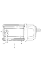
屋外に設置される昇降装置等の駆動源として使用される例えば、図1に示したようなモータ付き減速機10では、モータハウジング14の内部から外部にケーブル12を引き出す場合に、ケーブル12を挿通させるためにモータハウジング14に設けた貫通穴16から雨水等がモータハウジング14内部に浸入することを防止するための密閉構造が必要とされる。図6は、この種の密閉構造の一例を示す断面図である。図6(a)が密閉構造を構成する部品を展開した断面図であり、図6(b)が密閉構造を構成する部品が組み立てられた断面図を示している。
For example, in a
この密閉構造は、モータハウジング64にケーブル62の外皮62bに包まれた内線62aを挿通する貫通穴66が穿孔され、この貫通穴66は、側面66aがモータハウジング64の内側方向に向かって径が小さくなっており、底面66bにケーブル62の内線62aが挿通する挿通孔66cを有している。そして、ケーブル62の内線62aを囲繞する弾性体ブラケット65が貫通穴66に挿入されている。この弾性体ブラケット65は、貫通穴66と嵌合するように、その側面65aがモータハウジング64の内側方向に向かって径が小さくなっていると共に、モータハウジング64の外表面と接する鍔部65bを有している。そして、弾性体ブラケット65の側面65aを貫通穴66の側面66aに、弾性体ブラケット65の鍔部65aをモータハウジング64の外表面に圧接するためのケーブル固定板63を有しており、このケーブル固定板63とモータハウジング64で弾性体ブラケット65を挟持して、ケーブル固定板63を固定用ボルト61でモータハウジング64に螺刻したねじ穴67にねじ締めすることにより、ケーブル62とモータハウジング64との隙間を密閉している(例えば、特許文献1参照)。
In this sealed structure, a
ところが、前述した密閉構造では、弾性体ブラケット65に貫通穴66の側面66aからと底面66bから応力が加わり、弾性体ブラケット65が早期に劣化するという問題を抱えていた。また、固定用ボルト61を締めすぎることによって、弾性体ブラケット65の鍔部65aが損傷するという問題を抱えていた。
However, the above-described sealed structure has a problem in that stress is applied to the
そこで、本発明の目的は、二重のシール構造が形成されて長期に亘って密閉状態が保たれる密閉構造を備えた防水型モータ付き減速機を提供することにある。 SUMMARY OF THE INVENTION An object of the present invention is to provide a waterproof motor-equipped speed reducer having a sealed structure in which a double seal structure is formed and the sealed state is maintained for a long time.
請求項1に係る発明は、モータハウジングにケーブルを挿通する貫通穴が穿孔され、該貫通穴と前記ケーブルの隙間から前記モータハウジングの内部に水が浸入することを防止する密閉構造を備えた防水型モータ付き減速機において、前記ケーブルを囲繞し前記貫通穴に挿入される弾性体ブラケットが、前記モータハウジングの外表面と接する鍔部を有し、前記弾性体ブラケットの前記貫通穴に挿入される部分が、前記モータハウジングの内側方向に向かって径が小さくなる円錐形状を有し、前記弾性体ブラケットの円錐形状部の最大直径が、前記貫通穴の外側端部の直径より大きく、前記最大直径が、前記円錐形状部における前記鍔部との接合部分である根元の径であり、前記ケーブルを挿通すると共に前記鍔部を前記外表面に対して圧接するケーブル固定板を有し、前記鍔部が前記外表面に対して圧接された状態で、前記円錐形状部が前記モータハウジングにおいて前記貫通穴のみと密着部分にて密着すると共に、前記鍔部と前記外表面とが密着する二重のシール構造が形成され、かつ前記円錐形状部が、前記貫通穴内において前記密着部分以外の部分で前記貫通穴と接触しておらず、前記密着部分には、前記根元および前記外側端部が含まれていることによって、前記の目的を達成するものである。
なお、本発明において、円錐形状とは、底面が円で側面の投影図が二等辺三角形である正式な円錐形状とは異なり、頂点側が底面に平行な面で切断された側面の投影図が台形である形状を意味している。
The invention according to claim 1 is provided with a waterproof structure in which a through hole through which a cable is inserted is drilled in the motor housing and water is prevented from entering the inside of the motor housing through a gap between the through hole and the cable. In the speed reducer with a type motor, the elastic body bracket that surrounds the cable and is inserted into the through hole has a flange portion that contacts the outer surface of the motor housing, and is inserted into the through hole of the elastic body bracket The portion has a conical shape whose diameter decreases toward the inner side of the motor housing, and the maximum diameter of the conical portion of the elastic bracket is larger than the diameter of the outer end portion of the through hole, and the maximum diameter Is a diameter of a base that is a joint portion of the conical portion with the flange, and the cable is inserted and the flange is pressed against the outer surface. And the conical portion is in close contact with only the through hole in the motor housing at the close contact portion in a state in which the flange is pressed against the outer surface. A double seal structure is formed in close contact with the outer surface, and the conical portion is not in contact with the through hole at a portion other than the close contact portion in the through hole. The object is achieved by including the root and the outer end.
In the present invention, the conical shape is different from the official conical shape in which the bottom surface is a circle and the side projection is an isosceles triangle, and the side projection obtained by cutting the apex side with a plane parallel to the bottom surface is a trapezoid. Means a shape.
請求項1に係る発明によれば、モータハウジングにケーブルを挿通する貫通穴が穿孔され、該貫通穴と前記ケーブルの隙間から前記モータハウジングの内部に水が浸入することを防止する密閉構造を備えた防水型モータ付き減速機において、前記ケーブルを囲繞し前記貫通穴に挿入される弾性体ブラケットが、前記モータハウジングの外表面と接する鍔部を有し、前記弾性体ブラケットの前記貫通穴に挿入される部分が、モータハウジングの内側方向に向かって径が小さくなる円錐形状を有し、前記弾性体ブラケットの円錐形状部の最大直径が、前記貫通穴の外側端部の直径より大きく、前記最大直径が、前記円錐形状部における前記鍔部との接合部分である根元の径であり、前記ケーブルを挿通すると共に前記鍔部を前記外表面に対して圧接するケーブル固定板を有し、前記鍔部が前記外表面に対して圧接された状態で、前記円錐形状部が前記モータハウジングにおいて前記貫通穴のみと密着部分にて密着すると共に、前記鍔部と前記外表面とが密着する二重のシール構造が形成され、かつ前記円錐形状部が、前記貫通穴内において前記密着部分以外の部分で前記貫通穴と接触しておらず、前記密着部分には、前記根元および前記外側端部が含まれていることによって、前記弾性体ブラケットに前記貫通穴の底面から応力が加わらないので、弾性体ブラケットの長寿命化が図られる。
また、弾性体ブラケットの円錐形状部の最大直径である根元の径が、貫通穴の外側端部の直径より大きいことによって、弾性体ブラケットの円錐形状部の根元付近、すなわち、円錐形状部と鍔部との接合部分付近と貫通穴の外側端部付近とが密着するとともに、弾性体ブラケットの鍔部とモータハウジングの外表面とが密着する二重のシール構造が形成されるので、密閉構造の防水性が向上する。
According to the first aspect of the present invention, the motor housing is provided with a sealing structure in which a through hole for inserting a cable is drilled, and water is prevented from entering the motor housing through a gap between the through hole and the cable. In the waterproof type reduction gear with a motor, an elastic bracket that surrounds the cable and is inserted into the through hole has a flange portion that contacts an outer surface of the motor housing, and is inserted into the through hole of the elastic bracket. The portion to be formed has a conical shape whose diameter decreases toward the inner side of the motor housing, and the maximum diameter of the conical portion of the elastic bracket is larger than the diameter of the outer end portion of the through hole, and the maximum The diameter is a diameter of a base that is a joint portion of the conical portion with the flange, and the cable is inserted and the flange is pressed against the outer surface. The conical portion is in close contact with only the through hole in the motor housing at the close contact portion in a state in which the flange is pressed against the outer surface. A double seal structure is formed in close contact with the outer surface, and the conical portion is not in contact with the through hole at a portion other than the close contact portion in the through hole. By including the root and the outer end portion, stress is not applied to the elastic bracket from the bottom surface of the through hole, so that the life of the elastic bracket can be extended.
In addition, the diameter of the root, which is the maximum diameter of the cone-shaped portion of the elastic bracket, is larger than the diameter of the outer end portion of the through hole, so that the vicinity of the root of the cone-shaped portion of the elastic bracket, that is, the cone-shaped portion and the flange A double seal structure is formed in which the vicinity of the joint portion with the portion and the vicinity of the outer end of the through hole are in close contact with each other, and the flange portion of the elastic bracket and the outer surface of the motor housing are in close contact with each other. Waterproofness is improved.
本発明は、モータハウジングにケーブルを挿通する貫通穴が穿孔され、該貫通穴と前記ケーブルの隙間から前記モータハウジングの内部に水が浸入することを防止する密閉構造を備えた防水型モータ付き減速機において、前記ケーブルを囲繞し前記貫通穴に挿入される弾性体ブラケットが、前記モータハウジングの外表面と接する鍔部を有し、前記弾性体ブラケットの前記貫通穴に挿入される部分が、前記モータハウジングの内側方向に向かって径が小さくなる円錐形状を有し、前記弾性体ブラケットの円錐形状部の最大直径が、前記貫通穴の外側端部の直径より大きく、前記最大直径が、前記円錐形状部における前記鍔部との接合部分である根元の径であり、前記ケーブルを挿通すると共に前記鍔部を前記外表面に対して圧接するケーブル固定板を有し、前記鍔部が前記外表面に対して圧接された状態で、前記円錐形状部が前記モータハウジングにおいて前記貫通穴のみと密着部分にて密着すると共に、前記鍔部と前記外表面とが密着する二重のシール構造が形成され、かつ前記円錐形状部が、前記貫通穴内において前記密着部分以外の部分で前記貫通穴と接触しておらず、
前記密着部分には、前記根元および前記外側端部が含まれているものであって、長期に亘って密閉状態が保たれる密閉構造を備えた防水型モータ付き減速機であれば、その具体的な実施の態様は、如何なるものであっても何ら構わない。
The present invention provides a reduction gear with a waterproof motor provided with a sealing structure in which a through hole for inserting a cable is drilled in the motor housing, and water is prevented from entering the motor housing through a gap between the through hole and the cable. In the machine, the elastic bracket that surrounds the cable and is inserted into the through hole has a flange portion that contacts the outer surface of the motor housing, and the portion that is inserted into the through hole of the elastic bracket is A conical shape having a diameter that decreases toward an inner side of the motor housing, wherein the maximum diameter of the conical portion of the elastic bracket is larger than a diameter of an outer end portion of the through hole, and the maximum diameter is the conical shape; The diameter of the base that is the joint portion with the flange in the shape portion, and the cable that inserts the cable and presses the flange against the outer surface In the state where the flange portion is in pressure contact with the outer surface, the conical portion is in close contact with only the through hole in the motor housing at the close contact portion, and the flange portion and the outer surface A double seal structure is formed in close contact with the surface, and the conical portion is not in contact with the through hole at a portion other than the close contact portion in the through hole,
The close contact portion includes the root and the outer end portion, and is a specific example of a speed reducer with a waterproof motor having a sealed structure that maintains a sealed state for a long time. Any specific embodiment may be used.
まず、本発明の防水型モータ付き減速機の基本的な構成について、図2に基づいて説明する。図2は、本発明による防水型モータ付き減速機の密閉構造の基本的な構成を示す断面図であり、図2(a)が密閉構造を構成する部品を展開した断面図であり、図2(b)が密閉構造を構成する部品が組み立てられた断面図を示している。 First, the basic structure of the speed reducer with a waterproof motor according to the present invention will be described with reference to FIG. 2 is a cross-sectional view showing a basic structure of the sealing structure of the speed reducer with a waterproof motor according to the present invention, and FIG. 2 (a) is a sectional view in which components constituting the sealing structure are developed. (B) has shown sectional drawing with which the components which comprise a sealing structure were assembled.
この密閉構造は、モータハウジング24にケーブル22の外皮22bに包まれた内線22aを挿通する貫通穴26が穿孔されている。この貫通穴26は、モータハウジング24の外側と内側で同径の平行円筒穴である。そして、ケーブル22の内線22aを囲繞する弾性体ブラケット25が貫通穴26に挿入されている。この弾性体ブラケット25は、その側面25aがモータハウジング24の内側方向に向かって径が小さくなっている円錐形状を有していると共に、モータハウジング24の外表面と接する鍔部25bを有している。弾性体ブラケット25の円錐形状部の根元の径、すなわち該円錐形状部の最大直径は、貫通穴の径よりも若干小さく、すなわち、弾性体ブラケット25の円錐形状部の根元と貫通穴の間には、図2(b)に示したように隙間G1を有している。したがって、弾性体ブラケット25の側面25aは、貫通穴26の側面26aと接していない。そのため、弾性体ブラケット25の円錐形状部がモータハウジング24から応力を受けることがなく、弾性体ブラケット25の長寿命化が図られる。
In this sealed structure, a
また、弾性体ブラケット25の鍔部25bをモータハウジング24の外表面に圧接するためのケーブル固定板23を有しており、このケーブル固定板23とモータハウジング24で弾性体ブラケット25の鍔部25bを挟持して、ケーブル固定板23を固定用ボルト21でモータハウジング24に螺刻したねじ穴27にねじ締めすることにより、ケーブル22とモータハウジング24との隙間を密閉している。
In addition, a
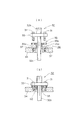
次に、本発明の防水型モータ付き減速機の一実施例について、図3に基づいて説明する。図3は、本発明による防水型モータ付き減速機の密閉構造の一例を示す断面図であり、図3(a)が密閉構造を構成する部品を展開した断面図であり、図3(b)が密閉構造を構成する部品が組み立てられた断面図を示している。 Next, an embodiment of a speed reducer with a waterproof motor according to the present invention will be described with reference to FIG. FIG. 3 is a cross-sectional view showing an example of a sealing structure of a speed reducer with a waterproof motor according to the present invention, in which FIG. 3 (a) is a cross-sectional view in which components constituting the sealing structure are developed, and FIG. FIG. 2 shows a cross-sectional view in which parts constituting a sealed structure are assembled.
この密閉構造は、モータハウジング34にケーブル32の外皮32bに包まれた内線32aを挿通する貫通穴36が穿孔されている。この貫通穴36は、モータハウジング34の外側と内側で同径の平行穴である。そして、ケーブル32の内線32aを囲繞する弾性体ブラケット35が貫通穴36に挿入されている。この弾性体ブラケット35は、その側面35aがモータハウジング34の内側方向に向かって径が小さくなっている円錐形状を有していると共に、モータハウジング34の外表面と接する鍔部35bを有している。弾性体ブラケット35の円錐形状部の根元の径は、貫通穴36の外側端部の径よりも若干大きく、すなわち、弾性体ブラケット35の円錐形状部の根元付近と貫通穴36の外側端部付近には、図3(b)に示したように密着部分G2を有している。このように、円錐形状部は、モータハウジング34において貫通穴36のみと密着部分G2にて密着しており、密着部分G2には、円錐形状部の根元および貫通穴36の外側端部が含まれている。
In this sealed structure, a
また、弾性体ブラケット35の鍔部35bをモータハウジング34の外表面に圧接するためのケーブル固定板33を有しており、このケーブル固定板33とモータハウジング34で弾性体ブラケット35の鍔部35bを挟持して、ケーブル固定板33を固定用ボルト31でモータハウジング34に螺刻したねじ穴37にねじ締めすることにより、ケーブル32とモータハウジング34との隙間を密閉している。
Further, a
したがって、本実施例においては、弾性体ブラケット35の円錐形状部の根元付近、すなわち、円錐形状部と鍔部との接合部分付近と貫通穴の外側端部付近とが密着するとともに、弾性体ブラケット35の鍔部35bとモータハウジングの外表面とが密着する二重のシール構造が形成されるので、密閉構造の防水性が向上する。
そして、図3(b)に示されるように、鍔部35bがモータハウジング34の外表面に対して圧接された状態で、円錐形状部は、貫通穴36内において密着部分G2以外の部分で貫通穴36と接触していない。
Therefore, in the present embodiment, the vicinity of the base of the conical portion of the
As shown in FIG. 3B, the conical portion penetrates at a portion other than the close contact portion G <b> 2 in the through
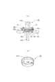
次に、本発明の防水型モータ付き減速機の別の一実施例について、図4に基づいて説明する。図4は、本発明による防水型モータ付き減速機の密閉構造の一例を示す図であり、図4(a)が密閉構造を示した断面図であり、図4(b)が本実施例の密閉構造を構成する主要構成部品であるケーブル固定板を示した斜視図である。 Next, another embodiment of the speed reducer with a waterproof motor according to the present invention will be described with reference to FIG. FIG. 4 is a view showing an example of a sealing structure of a speed reducer with a waterproof motor according to the present invention, FIG. 4 (a) is a sectional view showing the sealing structure, and FIG. 4 (b) is a diagram of this embodiment. It is the perspective view which showed the cable fixing plate which is the main components which comprise a sealing structure.
この密閉構造は、モータハウジング44にケーブル42の外皮42bに包まれた内線42aを挿通する貫通穴46が穿孔されている。この貫通穴46は、モータハウジング44の外側と内側で同径の平行円筒穴である。そして、ケーブル42の内線42aを囲繞する弾性体ブラケット45が貫通穴46に挿入されている。この弾性体ブラケット45は、その側面45aがモータハウジング44の内側方向に向かって径が小さくなっている円錐形状を有していると共に、モータハウジング44の外表面と接する鍔部45bを有している。
In this sealed structure, a through
また、弾性体ブラケット45の鍔部45bをモータハウジング44の外表面に圧接するためのケーブル固定板43を有しており、このケーブル固定板43とモータハウジング44で弾性体ブラケット45の鍔部45bを挟持して、ケーブル固定板43を固定用ボルト41でモータハウジング44に螺刻したねじ穴にねじ締めすることにより、ケーブル42とモータハウジング44との隙間を密閉している。
Further, a
このケーブル固定板43は、その外周縁部のモータハウジング44と対向する側に、図4(b)に示すように全周にわたり、弾性体ブラケット45の鍔部45bの厚みよりも高さの低い突出壁43aが突設されている。したがって、ケーブル固定板43とモータハウジング44との間隔が一定に保たれるので、固定用ボルト41を締めすぎて、弾性体ブラケット45の鍔部45aが損傷することが防止される。
As shown in FIG. 4B, the
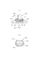
次に、本発明の防水型モータ付き減速機のさらに別の一実施例について、図5に基づいて説明する。図5は、本発明による防水型モータ付き減速機の密閉構造の一例を示す図であり、図5(a)が密閉構造を示した断面図であり、図5(b)が本実施例の密閉構造を構成する主要構成部品であるケーブル固定板を示した斜視図である。 Next, still another embodiment of the speed reducer with a waterproof motor according to the present invention will be described with reference to FIG. FIG. 5 is a view showing an example of a sealing structure of a speed reducer with a waterproof motor according to the present invention, FIG. 5 (a) is a sectional view showing the sealing structure, and FIG. 5 (b) is a diagram of the present embodiment. It is the perspective view which showed the cable fixing plate which is the main components which comprise a sealing structure.
この密閉構造は、モータハウジング54にケーブル52の外皮52bに包まれた内線52aを挿通する貫通穴56が穿孔されている。この貫通穴56は、モータハウジング54の外側と内側で同径の平行穴である。そして、ケーブル52の内線52aを囲繞する弾性体ブラケット55が貫通穴56に挿入されている。この弾性体ブラケット55は、その側面55aがモータハウジング54の内側方向に向かって径が小さくなっている円錐形状を有していると共に、モータハウジング54の外表面と接する鍔部55bを有している。
In this sealed structure, a through
また、弾性体ブラケット55の鍔部55bをモータハウジング54の外表面に圧接するためのケーブル固定板53を有しており、このケーブル固定板53とモータハウジング54で弾性体ブラケット55の鍔部55bを挟持して、ケーブル固定板53を固定用ボルト51でモータハウジング54に螺刻したねじ穴にねじ締めすることにより、ケーブル52とモータハウジング54との隙間を密閉している。
Further, a
このケーブル固定板53は、その外周縁部のモータハウジング54と対向する側に、図5(b)に示すように少なくとも3箇所以上(本実施例では4箇所)に等間隔に、弾性体ブラケット55の鍔部55bの厚みよりも高さの低い突出脚53aが突設されている。したがって、ケーブル固定板53とモータハウジング54との間隔が一定に保たれるので、固定用ボルト51を締めすぎて、弾性体ブラケット55の鍔部55aが損傷することが防止される。
As shown in FIG. 5B, the
本発明は、長期に亘って密閉状態が保たれる密閉構造を備えた防水型モータ付き減速機を提供するものであって、その産業上の利用可能性はきわめて高い。 The present invention provides a speed reducer with a waterproof motor having a sealed structure that keeps a sealed state for a long time, and its industrial applicability is extremely high.
10 ・・・ モータ付き減速機
12、22、32、42、52、62 ・・・ ケーブル
22a、32a、42a、52a、62a ・・・ (ケーブルの)内線
22b、32b、42b、52b、62b ・・・ (ケーブルの)外皮
14、24、34、44、54、64 ・・・ モータハウジング
25、35、45、55、65 ・・・ 弾性体ブラケット
25a、35a、45a、55a、65a ・・・ (弾性体ブラケットの)側面
25b、35b、45b、55b、65b ・・・ (弾性体ブラケットの)鍔部
16、26、36、46、56、66 ・・・ 貫通穴
16a、26a、36a、46a、56a、66a ・・・ (貫通穴の)側面
66b ・・・ (貫通穴の)底面
66c ・・・ (貫通穴の)挿通孔
27、37、47、57、67 ・・・ ねじ穴
10 ... Reducer with
Claims (1)
前記ケーブルを囲繞し前記貫通穴に挿入される弾性体ブラケットが、前記モータハウジングの外表面と接する鍔部を有し、
前記弾性体ブラケットの前記貫通穴に挿入される部分が、前記モータハウジングの内側方向に向かって径が小さくなる円錐形状を有し、
前記弾性体ブラケットの円錐形状部の最大直径が、前記貫通穴の外側端部の直径より大きく、
前記最大直径が、前記円錐形状部における前記鍔部との接合部分である根元の径であり、
前記ケーブルを挿通すると共に前記鍔部を前記外表面に対して圧接するケーブル固定板を有し、
前記鍔部が前記外表面に対して圧接された状態で、前記円錐形状部が前記モータハウジングにおいて前記貫通穴のみと密着部分にて密着すると共に、前記鍔部と前記外表面とが密着する二重のシール構造が形成され、かつ前記円錐形状部が、前記貫通穴内において前記密着部分以外の部分で前記貫通穴と接触しておらず、
前記密着部分には、前記根元および前記外側端部が含まれていることを特徴とする防水型モータ付き減速機。 In a speed reducer with a waterproof motor provided with a sealed structure that has a through hole through which a cable is inserted into the motor housing and prevents water from entering the inside of the motor housing from the gap between the through hole and the cable.
An elastic bracket that surrounds the cable and is inserted into the through hole has a flange portion that contacts an outer surface of the motor housing,
The portion inserted into the through hole of the elastic body bracket has a conical shape whose diameter decreases toward the inner side of the motor housing,
The maximum diameter of the conical portion of the elastic bracket is larger than the diameter of the outer end of the through hole;
The maximum diameter is a diameter of a base that is a joint portion with the flange portion in the conical portion,
A cable fixing plate for inserting the cable and press-contacting the flange with the outer surface;
In a state in which the flange portion is in pressure contact with the outer surface, the cone-shaped portion is in close contact with only the through hole in the motor housing at the contact portion, and the flange portion and the outer surface are in close contact with each other. A heavy seal structure is formed, and the conical portion is not in contact with the through-hole in a portion other than the tight-contact portion in the through-hole,
The reduction gear with a waterproof motor, wherein the close contact portion includes the root and the outer end.
Priority Applications (1)
| Application Number | Priority Date | Filing Date | Title |
|---|---|---|---|
| JP2011265126A JP5259808B2 (en) | 2011-12-02 | 2011-12-02 | Reducer with waterproof motor |
Applications Claiming Priority (1)
| Application Number | Priority Date | Filing Date | Title |
|---|---|---|---|
| JP2011265126A JP5259808B2 (en) | 2011-12-02 | 2011-12-02 | Reducer with waterproof motor |
Related Parent Applications (1)
| Application Number | Title | Priority Date | Filing Date |
|---|---|---|---|
| JP2007194572A Division JP4906624B2 (en) | 2007-07-26 | 2007-07-26 | Reducer with waterproof motor |
Publications (2)
| Publication Number | Publication Date |
|---|---|
| JP2012095526A JP2012095526A (en) | 2012-05-17 |
| JP5259808B2 true JP5259808B2 (en) | 2013-08-07 |
Family
ID=46388241
Family Applications (1)
| Application Number | Title | Priority Date | Filing Date |
|---|---|---|---|
| JP2011265126A Expired - Fee Related JP5259808B2 (en) | 2011-12-02 | 2011-12-02 | Reducer with waterproof motor |
Country Status (1)
| Country | Link |
|---|---|
| JP (1) | JP5259808B2 (en) |
Families Citing this family (1)
| Publication number | Priority date | Publication date | Assignee | Title |
|---|---|---|---|---|
| KR102618783B1 (en) * | 2020-07-07 | 2023-12-28 | (주)제이에스엔지니어링 | Motor integrated management apparatus |
Family Cites Families (4)
| Publication number | Priority date | Publication date | Assignee | Title |
|---|---|---|---|---|
| JPS5295003U (en) * | 1976-01-14 | 1977-07-16 | ||
| JPS534201U (en) * | 1976-06-30 | 1978-01-14 | ||
| JPS55112464U (en) * | 1979-02-01 | 1980-08-07 | ||
| JP4075718B2 (en) * | 2003-07-28 | 2008-04-16 | 三菱自動車工業株式会社 | Seal structure |
-
2011
- 2011-12-02 JP JP2011265126A patent/JP5259808B2/en not_active Expired - Fee Related
Also Published As
| Publication number | Publication date |
|---|---|
| JP2012095526A (en) | 2012-05-17 |
Similar Documents
| Publication | Publication Date | Title |
|---|---|---|
| CA2832651C (en) | Raintight compression connector and raintight compression coupler for securing electrical metallic tubing or rigid metallic conduit | |
| WO2014024785A1 (en) | Grommet | |
| EA201070574A1 (en) | THREADED CONNECTION, CONTAINING A LESS THEME ONE THREAD THREAD ELEMENT WITH A FRONT END FOR METAL PIPE | |
| RU2697585C2 (en) | Sealing device | |
| JP4906624B2 (en) | Reducer with waterproof motor | |
| RU2007126262A (en) | CABLE INPUT WITH DOUBLE SEAL PACKAGE | |
| JP5259808B2 (en) | Reducer with waterproof motor | |
| JP4276234B2 (en) | Sleeve for cable insertion and pipe penetration | |
| EP2546939A3 (en) | A housing assembly and method of assembling same | |
| WO2012161033A1 (en) | Hole plug | |
| JP2016050597A (en) | Stud bolt, and member jointing structure | |
| JP2007333027A (en) | Sealing structure and bolt | |
| CN207652005U (en) | Inverter and its Waterproof connector of cable | |
| CN114585845B (en) | Round seals | |
| JP6194069B1 (en) | Cable gland | |
| KR20150080987A (en) | Set anchor bolts | |
| KR200461595Y1 (en) | Cable Gland | |
| US10359070B2 (en) | Seal structure and control cable unit | |
| WO2021014497A1 (en) | Water-proof gasket structure for electronic device casing and electronic device casing | |
| WO2020075361A1 (en) | Cable gland | |
| JP2015135889A (en) | Capacitor | |
| JP5146740B2 (en) | Step mounting structure | |
| EP1995578A3 (en) | Sensor mounting assembly | |
| JP6585332B2 (en) | Ant protection device | |
| JP6299577B2 (en) | Grommet and wire with grommet |
Legal Events
| Date | Code | Title | Description |
|---|---|---|---|
| A977 | Report on retrieval |
Free format text: JAPANESE INTERMEDIATE CODE: A971007 Effective date: 20130416 |
|
| TRDD | Decision of grant or rejection written | ||
| A01 | Written decision to grant a patent or to grant a registration (utility model) |
Free format text: JAPANESE INTERMEDIATE CODE: A01 Effective date: 20130423 |
|
| A61 | First payment of annual fees (during grant procedure) |
Free format text: JAPANESE INTERMEDIATE CODE: A61 Effective date: 20130424 |
|
| FPAY | Renewal fee payment (event date is renewal date of database) |
Free format text: PAYMENT UNTIL: 20160502 Year of fee payment: 3 |
|
| R150 | Certificate of patent or registration of utility model |
Ref document number: 5259808 Country of ref document: JP Free format text: JAPANESE INTERMEDIATE CODE: R150 Free format text: JAPANESE INTERMEDIATE CODE: R150 |
|
| S533 | Written request for registration of change of name |
Free format text: JAPANESE INTERMEDIATE CODE: R313533 |
|
| R350 | Written notification of registration of transfer |
Free format text: JAPANESE INTERMEDIATE CODE: R350 |
|
| S111 | Request for change of ownership or part of ownership |
Free format text: JAPANESE INTERMEDIATE CODE: R313111 |
|
| R350 | Written notification of registration of transfer |
Free format text: JAPANESE INTERMEDIATE CODE: R350 |
|
| LAPS | Cancellation because of no payment of annual fees |