JP5259695B2 - Membrane pump position control by offset valve shaft - Google Patents
Membrane pump position control by offset valve shaft Download PDFInfo
- Publication number
- JP5259695B2 JP5259695B2 JP2010506632A JP2010506632A JP5259695B2 JP 5259695 B2 JP5259695 B2 JP 5259695B2 JP 2010506632 A JP2010506632 A JP 2010506632A JP 2010506632 A JP2010506632 A JP 2010506632A JP 5259695 B2 JP5259695 B2 JP 5259695B2
- Authority
- JP
- Japan
- Prior art keywords
- membrane
- valve
- valve spool
- transport chamber
- pump
- Prior art date
- Legal status (The legal status is an assumption and is not a legal conclusion. Google has not performed a legal analysis and makes no representation as to the accuracy of the status listed.)
- Active
Links
Images


Classifications
-
- F—MECHANICAL ENGINEERING; LIGHTING; HEATING; WEAPONS; BLASTING
- F04—POSITIVE - DISPLACEMENT MACHINES FOR LIQUIDS; PUMPS FOR LIQUIDS OR ELASTIC FLUIDS
- F04B—POSITIVE-DISPLACEMENT MACHINES FOR LIQUIDS; PUMPS
- F04B43/00—Machines, pumps, or pumping installations having flexible working members
- F04B43/02—Machines, pumps, or pumping installations having flexible working members having plate-like flexible members, e.g. diaphragms
- F04B43/06—Pumps having fluid drive
- F04B43/067—Pumps having fluid drive the fluid being actuated directly by a piston
-
- F—MECHANICAL ENGINEERING; LIGHTING; HEATING; WEAPONS; BLASTING
- F04—POSITIVE - DISPLACEMENT MACHINES FOR LIQUIDS; PUMPS FOR LIQUIDS OR ELASTIC FLUIDS
- F04B—POSITIVE-DISPLACEMENT MACHINES FOR LIQUIDS; PUMPS
- F04B43/00—Machines, pumps, or pumping installations having flexible working members
- F04B43/0009—Special features
- F04B43/0081—Special features systems, control, safety measures
-
- F—MECHANICAL ENGINEERING; LIGHTING; HEATING; WEAPONS; BLASTING
- F04—POSITIVE - DISPLACEMENT MACHINES FOR LIQUIDS; PUMPS FOR LIQUIDS OR ELASTIC FLUIDS
- F04B—POSITIVE-DISPLACEMENT MACHINES FOR LIQUIDS; PUMPS
- F04B43/00—Machines, pumps, or pumping installations having flexible working members
- F04B43/02—Machines, pumps, or pumping installations having flexible working members having plate-like flexible members, e.g. diaphragms
- F04B43/06—Pumps having fluid drive
- F04B43/073—Pumps having fluid drive the actuating fluid being controlled by at least one valve
-
- F—MECHANICAL ENGINEERING; LIGHTING; HEATING; WEAPONS; BLASTING
- F05—INDEXING SCHEMES RELATING TO ENGINES OR PUMPS IN VARIOUS SUBCLASSES OF CLASSES F01-F04
- F05B—INDEXING SCHEME RELATING TO WIND, SPRING, WEIGHT, INERTIA OR LIKE MOTORS, TO MACHINES OR ENGINES FOR LIQUIDS COVERED BY SUBCLASSES F03B, F03D AND F03G
- F05B2210/00—Working fluid
- F05B2210/10—Kind or type
- F05B2210/11—Kind or type liquid, i.e. incompressible
Description
本願は、2007年5月2日にされた米国特許出願第11/743,505号に基づく優先権を主張して2008年5月1日にされ、米国を除く全指定国に対する出願人が米国法人であるワナー・エンジニアリング・インコーポレイテッド、米国に対する出願人が米国民であるリチャード・ディ・ヘンブリーであるPCT国際出願である。 This application was filed on May 1, 2008, claiming priority based on US patent application Ser. No. 11 / 743,505, filed May 2, 2007, and applicants for all designated countries except the United States Wanner Engineering Inc., a legal entity, is a PCT international application whose applicant to the United States is Richard Di Henbury, a US citizen.
本発明は、流体ポンプ、より詳しくは油圧で駆動される膜ポンプに関する。 The present invention relates to a fluid pump, and more particularly to a hydraulically driven membrane pump.
油圧で駆動される膜ポンプは、少なくとも2群に分類される。第1群は、油圧ピストンまたは油圧プランジャの行程と膜の行程が異なるポンプである。このポンプは、非同期ポンプと呼ばれる。非同期ポンプは、通常、撓みが少量(「短行程」)で直径が大きい膜を持つのが好ましい大径膜ポンプの計量(metering)に用いられる。短行程の膜は、一般により長い行程の油圧プランジャまたはピストンによって駆動される。長い行程のピストンは、小径のピストンの使用を可能にし、その結果、ピストンをその行程に亘って動かせるクランク軸およびクランクケースに加わる荷重が小さくなる。 Membrane pumps driven by hydraulic pressure are classified into at least two groups. The first group is a pump in which the stroke of the hydraulic piston or the hydraulic plunger and the stroke of the membrane are different. This pump is called an asynchronous pump. Asynchronous pumps are typically used for metering large-diameter membrane pumps, which preferably have a membrane with a small diameter ("short stroke") and a large diameter. The short stroke membrane is typically driven by a longer stroke hydraulic plunger or piston. Long stroke pistons allow the use of small diameter pistons, resulting in less load on the crankshaft and crankcase that can move the pistons over the stroke.
第2群は、膜の中心が油圧ピストンと同じ距離動くポンプである。このポンプは、同期ポンプと呼ばれる。同期ポンプにおける膜の位置は、ピストン内に設けられ、ピストンと膜中心の距離を一定に保つ弁によって制御される。 The second group is a pump whose membrane center moves the same distance as the hydraulic piston. This pump is called a synchronous pump. The position of the membrane in the synchronous pump is controlled by a valve that is provided in the piston and keeps the distance between the piston and the membrane center constant.
同期ポンプにおいて膜位置を制御する弁システムの例は、この言及により本願に包含される米国特許第3,884,598号(ワナー)に開示されている。ワナーは、ピストンに対する膜の位置を検知して、膜の位置を一定に保つように働くシステムを開示する。このシステムは、行程端にあるストップ面に接触しなくて済むエラストマの膜を用いることができるので、高速動作しなければならないポンプや摩耗性の材料をポンピングするポンプに有用である。しかし、このシステムは、ピストンが膜の行程距離以上に移動すると、膜の背後にある作動油の量を適切に維持できず、ポンプが適切に動かなくなる。 An example of a valve system for controlling membrane position in a synchronous pump is disclosed in US Pat. No. 3,884,598 (Wanner), which is hereby incorporated by reference. Wanner discloses a system that senses the position of the membrane relative to the piston and serves to keep the position of the membrane constant. This system is useful for pumps that must operate at high speeds or pumps that are wearable because they can use an elastomeric membrane that does not need to contact the stop surface at the end of the stroke. However, this system cannot properly maintain the amount of hydraulic fluid behind the membrane if the piston moves beyond the membrane travel distance and the pump will not operate properly.
非同期ポンプの幾つかの例は、米国特許第5,246,351号(ホーン)、米国特許第5,667,368号(オーガスチン)、米国特許第4,883,412号(マリザード)に記載されている。これらのポンプは、総て膜位置の制御に類似の手法を用いている。各ポンプは、各行程の上端と下端で作動油の量を一時的に調整する。オーバーフィル状態は、膜が前方に移動しすぎて移動限に達したとき検出される。これは、作動油に通常圧力以上の高い圧力を生じさせ、弁を一時的に開かせ、過剰な作動油の幾らかを放出させる。この過剰圧力は、膜がストップに達したとき、または、膜を更に移動させるためにより高い圧力が必要な撓みの終点に膜が単に達したときに生じる。この圧力は、ポンピングされる流体には伝わらないので、膜を横切って不均衡な圧力降下が生じる。オーバーフィルによって生じる圧力を処理するこの方法は、膜が、損傷なく不均衡な圧力を処理できるに十分な材料と形状を持つことを要求する。膜の材料と形状に関するこの制限は、直径が非常に大きく撓みが少ない膜を使用する結果をもたらし、ポンプの寸法と費用を著しく増加させる。 Some examples of asynchronous pumps are described in US Pat. No. 5,246,351 (Horn), US Pat. No. 5,667,368 (Augustin), US Pat. No. 4,883,412 (Malizzard). ing. These pumps all use a similar approach to control the membrane position. Each pump temporarily adjusts the amount of hydraulic oil at the upper and lower ends of each stroke. An overfill condition is detected when the membrane has moved too far forward to reach the movement limit. This creates a high pressure above normal pressure in the hydraulic fluid, causing the valve to open temporarily, releasing some of the excess hydraulic fluid. This overpressure occurs when the membrane reaches a stop, or simply when the membrane reaches the end of deflection where higher pressure is required to move the membrane further. This pressure is not transmitted to the pumped fluid, resulting in an unbalanced pressure drop across the membrane. This method of handling the pressure caused by overfill requires that the membrane be of sufficient material and shape to handle an unbalanced pressure without damage. This limitation on membrane material and shape results in the use of membranes with very large diameters and low deflection, which significantly increases pump size and cost.
公知の油圧で駆動される非同期ポンプは、少なくとも上述の理由から、比較的小さく,大きな撓みを受けることができる非常に柔軟なエラストマ膜を使用することができなかった。その結果、この種の膜の使用は、同期ポンプに限定されていた。同期ポンプのピストン行程は、膜の行程が制限されているため、比較的小さくなければならない。このことは、クランク軸とクランクケースに、大径のピストンの大きな荷重を担わせて、ポンプの駆動側をより高価にする。 Known hydraulically driven asynchronous pumps have been unable to use a very flexible elastomeric membrane that is relatively small and capable of large deflections for at least the reasons described above. As a result, the use of this type of membrane has been limited to synchronous pumps. The piston stroke of the synchronous pump must be relatively small due to the limited membrane travel. This causes the crankshaft and crankcase to bear a large load of the large-diameter piston, making the pump drive side more expensive.
油圧で駆動されるポンプの他の例は、米国特許第3,769,879号(ロフクウィスト)に記載されている。ロフクウィストは、膜の行程毎に動いて、油タンクと膜の背後の作動油室(輸送室)との間のポートをピストンの行程端で一時的に開くスプールを開示する。このポートと動くスプールは、オーバーフィルまたはアンダーフィル状態を修正するため、行程毎に小パルスの作動油を通過させうるにすぎない。 Another example of a hydraulically driven pump is described in US Pat. No. 3,769,879 (Lofkwist). Lofquist discloses a spool that moves with each stroke of the membrane and temporarily opens a port between the oil tank and the hydraulic oil chamber (transport chamber) behind the membrane at the stroke end of the piston. The spool moving with this port can only pass a small pulse of hydraulic fluid per stroke to correct overfill or underfill conditions.
ロフクウィストは、極端なアンダーフィルまたはオーバーフィル状態(例えば、ポンピングされる流体の非常に低いまたは非常に高い入口圧力によって生じる状態)で重大な欠点を有する。極端なオーバーフィル状態では、各行程で通過できる小パルスの作動油は、オーバーフィルを直ちに修正するに不十分で、その結果、オーバーフィル状態を修正するに十分な行程が繰り返されるまで、膜に応力が加わる。ロフクウィストの他の欠点は、膜が付勢される方向に関係する。極端な状態(例えば、ポンプの入口側の閉塞などに起因するポンピングされる流体の低い入口圧力および出口圧力)で、ロフクウィストのシステムは、そうでなければ過剰充填された作動油を放出するのであるが、膜に付勢力が加わっていなくても輸送室に作動油を追加しようとする。その結果、オーバーフィルを解消できず、膜が損傷することになる。 Lofquist has significant drawbacks in extreme underfill or overfill conditions (eg, conditions caused by very low or very high inlet pressure of the pumped fluid). In extreme overfill conditions, a small pulse of hydraulic fluid that can pass in each stroke is insufficient to immediately correct the overfill, and as a result, until the stroke is repeated enough to correct the overfill condition, Stress is applied. Another drawback of Lofquist relates to the direction in which the membrane is biased. In extreme conditions (e.g. low inlet and outlet pressures of the pumped fluid due to blockage on the inlet side of the pump, etc.), Lofquist's system will release otherwise overfilled hydraulic fluid However, even if no urging force is applied to the membrane, it tries to add hydraulic oil to the transport chamber. As a result, the overfill cannot be eliminated and the film is damaged.
膜ポンプにおいて、膜位置の制御を改善する必要がある。 There is a need to improve the control of membrane position in membrane pumps.
本開示の一態様は、ピストン,膜,ポンプ室,輸送室,第1弁,第2弁,油タンクおよび弁スプールを備えた膜ポンプに関する。上記ピストンは、第1位置と第2位置の間で往復動するようになっている。上記膜は、上記ピストンの第1位置および第2位置に夫々関連する第1位置および第2位置の間で移動できる。上記輸送室は、膜の一方側に位置し、膜とピストンの相対位置によって部分的に区画され、作動油で充填される。上記ポンプ室は、膜の輸送室と反対側に位置する。上記油タンクは、上記第1弁および第2弁を介して上記輸送室に連通する。上記弁スプールは、輸送室内に位置し、第1位置にあるとき、第1弁および第2弁の開口を閉じ、第2位置にあるとき、第1弁の開口を閉じ、第2弁の開口を開き、第3位置にあるとき、第1弁の開口を開き、第2弁の開口を閉じるようになっている。弁スプールは、弁スプールを第2位置へ動かす充填過剰状態が輸送室に生じるまで、あるいは、弁スプールを第3位置へ動かす充填不足状態が輸送室に生じるまで、一般に第1位置を維持する。膜ポンプは、膜の移動部分に取り付けられ,弁スプールに係合してこの弁スプールを第1,第2,第3位置の間で動かす作動部材を更に備える。作動部材は、ロッドおよび膜に付勢力を与えるために用いられるばねの軸とは異なる軸に弁スプールを配置することを可能にする。弁スプールは、膜,膜ロッド,ばねおよびポンプの主ピストンから分離した軸に配置することができる。 One aspect of the present disclosure relates to a membrane pump including a piston, a membrane, a pump chamber, a transport chamber, a first valve, a second valve, an oil tank, and a valve spool. The piston reciprocates between a first position and a second position. The membrane is movable between a first position and a second position associated with the first position and the second position of the piston, respectively. The transport chamber is located on one side of the membrane, is partially partitioned by the relative position of the membrane and the piston, and is filled with hydraulic oil. The pump chamber is located on the opposite side of the membrane from the transport chamber. The oil tank communicates with the transport chamber via the first valve and the second valve. The valve spool is located in the transport chamber. When the valve spool is in the first position, the first valve and the second valve are closed. When the valve spool is in the second position, the first valve is closed and the second valve is opened. And when in the third position, the opening of the first valve is opened and the opening of the second valve is closed. The valve spool generally maintains the first position until an overfill condition occurs in the transport chamber that moves the valve spool to the second position, or until an underfill condition occurs in the transport chamber that moves the valve spool to the third position. The membrane pump further includes an actuating member attached to the moving portion of the membrane and engaging the valve spool to move the valve spool between the first, second and third positions. The actuating member allows the valve spool to be placed on a different axis than the axis of the spring used to apply the biasing force to the rod and membrane. The valve spool can be placed on a shaft that is separate from the membrane, membrane rod, spring and the main piston of the pump.
このような膜ポンプを膜ポンプ内の作動油圧力を制御するために操作する方法も、本開示の重要な態様である。 A method of operating such a membrane pump to control the hydraulic oil pressure in the membrane pump is also an important aspect of the present disclosure.
以上の概括は、本明細書に開示された発明の態様の総ての実施形態または実行例を記述することを意図しない。次の詳細な説明の図は、発明の特定の態様が如何に実施されるかを例示する。一方、特定の実施形態が図示され説明されるが、開示がこのような実施形態に限定されないものと理解されなければならない。 The above summary is not intended to describe every embodiment or implementation of an aspect of the invention disclosed herein. The following detailed description drawings illustrate how certain aspects of the invention may be implemented. On the other hand, although particular embodiments are shown and described, it should be understood that the disclosure is not limited to such embodiments.
種々の実施形態を図を参照して説明するが、幾つかの図を通じて同じ部材およびアセンブリには、同じ参照番号を用いる。種々の実施形態への言及は、添付の請求項の範囲を制限するものではない。また、本明細書で述べる実施形態は、添付の請求項を限定する意図ではなく、多くの可能な実施形態の幾つかを述べているにすぎない。 Various embodiments are described with reference to the drawings, wherein like reference numerals are used to refer to like members and assemblies throughout the several views. Reference to various embodiments does not limit the scope of the appended claims. Also, the embodiments described herein are not intended to limit the appended claims, but merely describe some of the many possible embodiments.
次の記載は、本発明を実施するのに適した環境を簡潔かつ一般的に述べるものである。要求されないが、本発明を膜ポンプの一般的背景において記述する。以下、膜位置を制御する装置およびシステムの構造,製造,使用の幾つかの例ならびに関連する使用法を述べる。 The following description briefly and generally describes an environment suitable for practicing the present invention. Although not required, the invention will be described in the general context of a membrane pump. The following describes some examples of the structure, manufacture, and use of devices and systems that control membrane position and related uses.
本開示は、概ね、油圧で駆動される膜ポンプなどの流体ポンプに関する。本開示の原理は、非同期ポンプにも同期ポンプにも等しく適用できる。非同期ポンプは、油圧ピストンの行程と膜の行程が相違する。膜は、一般に直径が比較的大きく、撓みが比較的少量になるように設定されている。この膜の短い行程は、遙かに長い行程の油圧プランジャまたはピストンで駆動される。油圧プランジャまたはピストンの行程が長ければ長いほど、ピストンの直径はより小さくて済み、ポンプのクランク軸やクランクケースに加わる荷重はより小さくなる。 The present disclosure relates generally to fluid pumps such as hydraulically driven membrane pumps. The principles of the present disclosure are equally applicable to asynchronous and synchronous pumps. In the asynchronous pump, the stroke of the hydraulic piston and the stroke of the membrane are different. The membrane is generally set to have a relatively large diameter and a relatively small amount of deflection. The short stroke of this membrane is driven by a much longer stroke hydraulic plunger or piston. The longer the stroke of the hydraulic plunger or piston, the smaller the piston diameter and the smaller the load on the pump crankshaft and crankcase.
同期ポンプは、膜の中心が油圧ピストンの移動距離と同じ距離移動するように構成されている。このようなポンプは、比較的小径のピストンを用いることに起因するクランクケースやクランク軸の荷重を最小化するために、膜が、ピストン行程に対応する長い距離だけ撓まなければならない。比較的小径のピストンを確保するために必要な程度に撓む膜が不可能な場合、ピストン直径を大きくしなければならず、その結果、クランク軸やクランクケースに大きな荷重が加わることになる。本開示は、膜の破損をもたらす予め定められた距離を超えて膜が伸張または後退しないことを保証するように膜位置の制御を助けるように、非同期ポンプおよび同期ポンプの双方に用いることができる。 The synchronous pump is configured such that the center of the membrane moves the same distance as the moving distance of the hydraulic piston. Such pumps require that the membrane bend a long distance corresponding to the piston stroke in order to minimize the load on the crankcase and crankshaft resulting from the use of a relatively small diameter piston. If a membrane that can be bent to the extent necessary to secure a relatively small-diameter piston is not possible, the piston diameter must be increased, resulting in a large load on the crankshaft and crankcase. The present disclosure can be used with both asynchronous and synchronous pumps to help control membrane position to ensure that the membrane does not stretch or retract beyond a predetermined distance that results in membrane failure. .
公知の膜位置制御システムの多くは、膜のポンピングされる流体と反対側の輸送室内の作動油の圧力状態に基づいて機能する。このような圧力に基づくシステムは、一般に、所定の圧力レベルに応動して開閉するリリーフ弁を用いている。リリーフ弁は、一般に、輸送室と油タンクの間に配置される。過剰圧力を軽減すべく設計されたシステムでは、最大圧力を超えると、リリーフ弁が一時的に開いて、作動油の幾らかを油タンクに逃がす。不足圧力を緩和すべく設計されたシステムでは、圧力が最低圧力以下に低下すると、別のリリーフ弁が一時的に開いて、幾らかの作動油を油タンクから輸送室に吸い込む。 Many of the known membrane position control systems function based on the pressure condition of the hydraulic fluid in the transport chamber opposite the membrane pumping fluid. Such pressure-based systems typically use a relief valve that opens and closes in response to a predetermined pressure level. The relief valve is generally arranged between the transport chamber and the oil tank. In systems designed to relieve overpressure, when the maximum pressure is exceeded, the relief valve temporarily opens, allowing some of the hydraulic oil to escape to the oil tank. In systems designed to relieve underpressure, when the pressure drops below the minimum pressure, another relief valve is temporarily opened to draw some hydraulic oil from the oil tank into the transport chamber.
このようなシステムにおいて過剰圧力は、一般に、撓み端などにあるストップに膜が達して、膜を更に撓ませるのに高い圧力を要する時点で生じる。過剰圧力状態に対処するため、膜は、高圧と低圧の繰り返しサイクルの後でも損傷に耐え得る比較的強くて柔軟でない材料から作られなければならない。直径を増加し,膜の撓み量を減少させた膜は、高圧状態に対処できるが、ポンプの寸法と価格を大きく増大させる。 In such systems, overpressure generally occurs when the membrane reaches a stop, such as at the flexure end, and requires high pressure to further deflect the membrane. In order to cope with overpressure conditions, the membrane must be made of a relatively strong and inflexible material that can withstand damage even after repeated high and low pressure cycles. A membrane with increased diameter and reduced membrane deflection can cope with high pressure conditions, but greatly increases the size and cost of the pump.
圧力に基づくシステムの他の問題は、キャビテーションである。輸送室内の過剰圧力は、ポンピングされる流体に通常は伝わらず、従って、膜を横切って圧力の不均衡状態(即ち、圧力降下)が生じる。この圧力降下は、ピストン行程の或る部分で真空状態をもたらす可能性があり、作動油にキャビテーションを起こし得る。キャビテーションは、作動油に曝される部材の摩耗(孔食)を増大させる。 Another problem with pressure based systems is cavitation. Overpressure in the transport chamber is not normally transferred to the pumped fluid, and therefore a pressure imbalance (ie, a pressure drop) occurs across the membrane. This pressure drop can result in a vacuum at some part of the piston stroke and can cause cavitation in the hydraulic fluid. Cavitation increases wear (pitting corrosion) of members exposed to hydraulic fluid.
本開示は、輸送室内の圧力ではなく、輸送室の体積に基づいて機能する。輸送室内の充填過剰または充填不足の体積状態に依存して、移動可能な弁スプールが、油タンクと輸送室の間にあるチェック弁の開口を開閉する位置の間で輸送室内において変位する。弁スプールを動かすのは、作動油によって生じる圧力状態ではなく、作動油そのものである。充填不足および充填過剰の体積状態は、ピストン行程の上死点または下死点で概ね最も良く評価される。本開示は、弁スプールがピストン行程の上死点または下死点のみで移動して、充填不足および充填過剰の状態を修正するように構成される。 The present disclosure works based on the volume of the transport chamber, not the pressure in the transport chamber. Depending on the overfilled or underfilled volume state in the transport chamber, the movable valve spool is displaced in the transport chamber between positions that open and close the check valve opening between the oil tank and the transport chamber. It is the hydraulic oil itself that moves the valve spool, not the pressure caused by the hydraulic oil. Underfill and overfill volume conditions are generally best evaluated at the top or bottom dead center of the piston stroke. The present disclosure is configured such that the valve spool moves only at the top dead center or bottom dead center of the piston stroke to correct underfill and overfill conditions.
この言及により本願に包含される本出願人による米国出願(US 2006/0239840 A1)は、油圧で駆動される膜ポンプの膜位置を制御するためのシステムであって、膜が行程の安全範囲内で動くシステムを開示する。このシステムは、作動油で満たされる輸送室が充填過剰または充填不足になったときに動く弁スプールを用いている。輸送室が充填過剰になると、ピストンが上死点にあるとき、膜は前方へ遠くまで移動する。この充填過剰位置は、弁スプールを動かして、輸送室から第1チェック弁を経て作動油を流出させるポートを開かせる。輸送室が充填不足になると、膜は後方へ遠くまで移動して、弁スプールをして、第2チェック弁を経て作動油を輸送室に流入させるポートを開かしめる。 Applicant's US application (US 2006/0239840 A1), which is incorporated herein by this reference, is a system for controlling the membrane position of a hydraulically driven membrane pump, where the membrane is within the safe range of the stroke. Disclose a system that runs on This system uses a valve spool that moves when a transport chamber filled with hydraulic fluid becomes overfilled or underfilled. When the transport chamber is overfilled, the membrane moves farther forward when the piston is at top dead center. This overfill position moves the valve spool to open a port through which hydraulic fluid flows out of the transport chamber via the first check valve. When the transport chamber becomes underfilled, the membrane moves farther backward, causing the valve spool to open a port through which hydraulic oil flows into the transport chamber via the second check valve.
上記米国出願(US 2006/0239840 A1)は、膜の中心に取り付けられたロッドと同軸の膜の軸に沿って配置された弁スプールを開示する。この膜のロッドは、輸送室内の作動油に、膜の反対側のポンピングされる流体よりも僅かに高い圧力を付加するバイアスばねの力に対抗して用いられる。ロッドは、また、充填過剰または充填不足状態が生じると、弁スプールに接触し、第1,第2チェック弁を上述のように動かすようになっている。同軸の弁スプールは、ロッドと接触するように設計されなければならず、同時に、膜のロッドの内部または外部にある同軸のばねを許容しなければならない。米国出願(US 2006/0239840 A1)に記載された膜ポンプの全体の構造および形状は、比較的複雑で、組み立てが難しくなる傾向があり、その結果、弁スプールや他の構成要素が好ましくない寸法になる。 The above US application (US 2006/0239840 A1) discloses a valve spool disposed along the axis of the membrane coaxial with a rod attached to the center of the membrane. This membrane rod is used against the force of the bias spring which applies a slightly higher pressure to the hydraulic oil in the transport chamber than the pumped fluid on the opposite side of the membrane. The rod also contacts the valve spool when an overfill or underfill condition occurs, causing the first and second check valves to move as described above. The coaxial valve spool must be designed to contact the rod and at the same time allow a coaxial spring inside or outside the membrane rod. The overall structure and shape of the membrane pump described in the US application (US 2006/0239840 A1) is relatively complex and tends to be difficult to assemble, so that valve spools and other components are unfavorable dimensions become.
本開示は、例えば米国出願(US 2006/0239840 A1)で用いられているよりも構成要素および構造が簡素な弁制御システムを提供する。このような構成要素として、膜の移動部分に取り付けられた作動部材がある。この作動部材は、充填過剰または充填不足状態の際、輸送室と油タンク間の作動油の流れを制御する弁スプールに係合する。上記作動部材は、膜のロッドおよび膜にバイアス圧力を加えるためのばねの軸と異なる軸に、弁スプールを配置することを可能にする。弁スプールを別の軸に配置することは、膜ポンプを種々の観点で簡素化できる。例えば、膜のロッドとバイアス圧力用のばねは、バイアス圧力を加えるという限られた機能のみを果たせば済む。このことは、通常、ばねの寸法を小さくでき、(膜のロッド内にばねを配置する場合)ばねを嵌め込む穴を小さくできることを意味する。さらに、弁スプール部材は、弁スプール用の穴に要求される高度に円滑な仕上げを必要としない。 The present disclosure provides a valve control system that is simpler in components and structure than used, for example, in the US application (US 2006/0239840 A1). As such a component there is an actuating member attached to the moving part of the membrane. The actuating member engages a valve spool that controls the flow of hydraulic oil between the transport chamber and the oil tank when overfilled or underfilled. The actuating member makes it possible to place the valve spool on a different axis than the axis of the membrane rod and the spring for applying a bias pressure to the membrane. Placing the valve spool on a separate shaft can simplify the membrane pump in various ways. For example, a membrane rod and a bias pressure spring need only perform a limited function of applying a bias pressure. This usually means that the size of the spring can be reduced and the hole into which the spring is fitted can be reduced (when the spring is placed in the membrane rod). Further, the valve spool member does not require the highly smooth finish required for the valve spool hole.
弁スプールを別の軸に配置することの他の利点は、弁スプールの直径を遙かに小さくできることである。弁スプールは、その軸に沿って膜バイアス用のばねを収容するための穴が不要になるので、直径を遙かに小さくでき、弁スプールを収容する対応する穴も、遙かに小さくできる。膜バイアス用のばねおよび弁スプールのための穴が小さいので、ポンプハウジング内において輸送室に生じる高圧に曝される部分の面積が減少し、その結果、ポンプ内に掛かるストレスが減少する。また、上記穴が小さいので、輸送室に必要とされる作動油の体積が減少し、システムのためのモジュールが小体積になり、体積効率が上昇する。 Another advantage of placing the valve spool on a separate shaft is that the diameter of the valve spool can be much smaller. Since the valve spool does not require a hole for accommodating the membrane biasing spring along its axis, the diameter can be much smaller and the corresponding hole for accommodating the valve spool can be much smaller. The small holes for the membrane biasing spring and valve spool reduce the area of the pump housing that is exposed to the high pressures that occur in the transport chamber, resulting in less stress on the pump. Also, since the hole is small, the volume of hydraulic oil required for the transport chamber is reduced, the module for the system is reduced in volume, and the volume efficiency is increased.
弁スプールを別の軸に配置することの更なる利点は、弁スプールを円筒形にする必要が最早ないことである。弁スプールは、セラミックの盤部材などの平坦な構造にできる。弁スプールの平坦な構造は、比較的低度の隙間シールインターフェイスを作る選択肢を提供でき、場合によって低価格の設計を提供できる。
図1〜4Aに示す膜ポンプの実施形態
A further advantage of placing the valve spool on a separate shaft is that the valve spool no longer needs to be cylindrical. The valve spool can be a flat structure such as a ceramic board member. The flat structure of the valve spool can provide an option to create a relatively low clearance seal interface, and in some cases can provide a low cost design.
Embodiment of the membrane pump shown in FIGS.
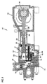
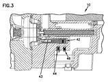
本開示の原理を図解した非同期膜ポンプ10の例を、図1〜4Aを参照して記述する。図1は、正常充填状態下で下死点(BDC)にあるポンプピストンを、図2は、正常充填状態下で上死点(TDC)にあるポンプピストンを、図3は、充填不足状態下で下死点にあるポンプピストンを、図4は、充填過剰状態下で上死点にあるポンプピストンを夫々示す。
An example of an
ポンプ10は、クランクケース12、ピストンハウジング14およびマニホールド16を有する。ピストンハウジング14は、油タンク18、輸送室20または作動油室およびプランジャ室22を区画する。マニホールド16は、ポンプ室24を区画し、入口弁72と出口弁74を有する。
The
クランクケース12内に、クランク軸26と連接棒28とスライダ30が配置されている。スライダ30は、プランジャ室22内に配置されたプランジャ32に連結される。輸送室20とプランジャ室22は、互いに連通しており、プランジャ室22に吸い込まれあるいはプランジャ室22から押し出された作動油が、膜を図1に示すように後退位置に引き込みあるいは図2に示すように伸張位置に押し出すようになっている。
A
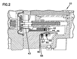
膜のロッド34は、輸送室20を通って延在する。ばね36は、ロッド34と同軸に配置され、輸送室20内をポンプ室24内よりも高い圧力状態に維持することを助けるべく、膜に後方へ向かう付勢力を加える。輸送室20をより高い圧力状態に維持すれば、入口吸い込み状態下でポンプ10の性能を改善できる。
A
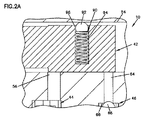
弁スプール用の穴54は、膜のロッド34の近傍のピストンハウジング14に設けられている。この穴は、弁スプール42を収容する寸法である。スプール穴52は、膜のロッド34の動きに平行な方向に弁スプール42が動けるような寸法になっている。弁スプール42は、アンダーフィル弁44の開口56を開くとともに、オーバーフィル弁46の開口64を閉ざす第1位置(図3,3Aに示すアンダーフィルの位置付け参照)と、開口56,64を実質的に閉ざす第2位置(図2,2Aに示す定常状態の位置付け参照)と、開口56を閉ざし、開口64を開く第3位置(図4,4Aに示すオーバーフィルの位置付け参照)の間で動くことができる。図2A,3A,4Aの拡大図は、定常状態,アンダーフィル状態(充填不足),オーバーフィル状態(充填過剰)の夫々における開口56,64の開閉状態をより明瞭に示している。
A
膜ポンプ10は、開口56に連繋するアンダーフィル弁44と、開口64に連繋するオーバーフィル弁46を有する。アンダーフィル弁44は、油タンク18の近傍に位置する他の開口57を有する。アンダーフィル弁44は、また、座58,ばね60およびプラグ62を有する。ばね60は、弁スプール42が移動して開口56を開くまで、プラグ62を座58に当接するように付勢する。開口56が開かれると、作動油はアンダーフィル弁44を経て輸送室20に吸い込まれる。オーバーフィル弁46は、座66,ボール68およびばね70を有する。ばね70は、弁スプール42が移動して開口64を開くまで、ボール68を座66に当接するように付勢する。開口64が開かれると、作動油は輸送室20からオーバーフィル弁46を経て押し出される。アンダーフィル弁44とオーバーフィル弁46は、作動油の一方向のみへの流れを許容するチェック弁である。
The
弁スプール42は、輸送室20内が充填不足,充填過剰および定常の状態であるとき、輸送室20と油タンク18の間の作動油の流れを制御する重要な機能を果たす。弁スプール42は、膜33の位置に応じて移動する。弁アーム43は、一端が膜33に固定され、他端が弁スプール42のスプール穴52内に位置する。スプール穴52は、定常状態における操作条件下での膜33の移動量よりも大きい長さを持つ。スプール穴52は、輸送室20内で充填過剰または充填不足の状態が生じるまで、弁アーム43が弁スプール42を動かすことなく自由に移動できる「滞留(ドウェル)域」を提供する。
The
ポンプ10の通常の高圧力動作において、プランジャピストン32とプランジャピストン32が内側を移動する穴31との間の隙間を経て、少量の作動油がプランジャ室22から油タンク18へ流れる。この作動油の損失は、ポンプ10の吸入行程中にアンダーフィル弁44を経て輸送室20に吸い込まれる作動油によって補われる。この通常動作では、弁スプール42は、アンダーフィル弁の開口56を図1,2,2Aに示すように開くような位置にある。この通常の釣合い位置は、膜33が下死点(BDC)に達して、開口56を経て輸送室20に流入する流れが、プランジャピストン32と穴31の間の隙間を経て流出する流れに等しくなるに十分なだけ開口56が開くように、膜に取り付いた弁アーム43が弁スプール42を後方へ動かしたとき達成される。この釣り合わせの過程は、輸送室20から流出する作動油の損失に伴って膜33が漸次後方へ移動するとき、ポンプ10の数行程に亘って起こる。輸送室20から流出する作動油の量とアンダーフィル弁44を経て輸送室20に流入する作動油の量が一旦均衡すると、弁スプール42は、作動油の損失率を変化させる何らかの変化がポンプの条件に生じない限り、静止状態を維持する。
In a normal high pressure operation of the
弁スプール42の図3,3A,4,4Aに示す他の位置への移動は、ポンプ10のポンピング条件に依存する。第1の一般的な条件は、ポンプ10の起動時に生じる。ポンプ10が停止中は、輸送室の作動油が、ばね36から膜33に加わる圧力またはポンプ10内の残留圧力によって、プランジャピストン32と穴31の間の隙間から洩れ出す。ポンプ10が起動されるとき、輸送室20には僅かな作動油しかないので、膜33は輸送室20内の遙かに後方へ移動し、プランジャピストン32は下死点に達している(例えば図3,3A参照。この状態は上述の充填不足状態である。充填不足状態が生じると、膜33と共に動く弁アーム43は、弁スプール42がオーバーフィル弁の開口64を完全に閉ざし、アンダーフィル弁の開口56を開くように弁スプール42を移動させる。)。弁スプール42がこの位置にあると、ポンプ10の吸入行程において、油タンク18の作動油がアンダーフィル弁44を経て輸送室20に吸い込まれる。ポンプの連続する各行程によって輸送室20の充填不足が緩和されると、弁アーム43は弁スプール42の前方に係合して、図1,2,2Aを参照して先に述べた定常状態の均衡位置に実質的に到達する。
The movement of the
第2の一般的な条件は、ポンプ10への入口ラインに制限があって、低圧入口状態および出口圧力の損失が起こる場合に生じる。低圧入口状態は、膜33を通常よりも遙かに前方へ移動させ、プランジャは上死点(TDC)に達している。この状態は、充填過剰状態と呼ばれ、図4,4Aに示される。充填過剰状態になると、弁アーム43は、弁スプール42がアンダーフィル弁の開口56を完全に閉ざし、オーバーフィル弁の開口64を開くように弁スプール42を前方へ移動させる。すると、過剰な作動油は、輸送室20から開口56およびオーバーフィル弁46を経て油タンク18に流出する。
The second common condition occurs when the inlet line to the
上述のように、弁スプールは、輸送室20に対して流入および流出する流れを釣り合わす均衡位置を探し求めて移動する。弁スプール42の位置は、ポンプの条件が変化して弁アーム43が弁スプール42を移動させるまで、変わることなく維持される。弁アーム42が振動や重力で自ら動くことを防ぐため、ポンプ10には、弁アーム43に係合するまでの弁スプール42の動きを阻止する装置が設けられる。ボール92とばね94を有するスプールリテーナ90が、弁スプール42のスプールリテーナ穴96に配置される。スプールリテーナ90は、スプール穴54に当接して摩擦力を生じさせ、弁スプール42が自ら動かないようにしている。
As described above, the valve spool moves in search of an equilibrium position that balances the flow in and out of the
特定のポンピング条件に対する均衡定常状態点の達成について、図1,2,2Aを参照して更に述べる。均衡定常状態下では、ポンピング条件に変化がない限り、弁スプール42は動かない。輸送室20に出入りする作動油の流れの微調整は、膜の上死点または下死点における極僅かな変化によってもたらされる。この変化は、1行程当たりの輸送室からの洩れ率をプランジャの変位で除した値に比例する。例えば、シリンダ変位が略200立方センチメートル(cc)のシールレスポンプを最大圧力で作動させた場合、輸送室からの洩れ率は、1行程当たり略1ccである。弁スプールがオーバーフィル弁およびアンダーフィル弁の開口56,64を、輸送室20の作動油がプランジャピストン32の外周のみから洩れ出すように閉ざしている場合、膜の行程位置は、膜の行程の略1/200だけ移動する。シリンダ変位が200ccの例では、膜33の移動は略38.1mmになるので、1行程当たりの下死点の減少は、略0.191mmである。膜の行程位置は、弁スプール42がアンダーフィル弁の開口56を開き始めるまで、各行程毎に0.191mmずつ後退する。アンダーフィル弁の開口56が一旦僅かに開くと、少量の作動油が吸入行程毎に輸送室20に流入する。つまり、流入する作動油が、輸送室20からプランジャピストン32の外周を経て流出する作動油率から減じられるので、行程毎の正味の損失は、次の行程でより少なくなる。
The achievement of equilibrium steady state points for specific pumping conditions is further described with reference to FIGS. Under equilibrium steady state, the
例えば、弁スプール42が、最初に移動するときに弁アーム43の係合によって開口を0.178mm開いているとすると、吸入行程で輸送室20に流入する作動油は0.5ccであり、輸送室20から流出する正味の作動油は、今や0.5ccになる。次の行程では、弁スプール42は、前回の移動量の半分だけ移動するだけで、各行程毎に調整量は減少し続ける。実際、この調整過程は、ポンプ10の数行程に亘って、ポンプの動作設定に応じて数秒以下の時間行われる。ポンプの条件が充填過剰を生じたときも、同様の過程が行われる。ポンプ10への入口に制限があって、ポンプ10の出口が低圧であると、充填過剰が生じる。充填過剰状態では、輸送室20は、各行程毎に徐々に少量ずつ(例えば、1行程につき1cc)作動油体積を増加させる。オーバーフィル弁の開口64を徐々に開くという同様の過程が、プランジャピストンの隙間から輸送室20に流入する作動油の量が,オーバーフィル弁46を経て輸送室20から流出する作動油の量に等しくなるまで行われる。
For example, when the
図1は、輸送室20から(例えばポンプ起動時に)空気を逃がすが、正常動作中は流体(作動油または油)の著しい洩れを防ぐ抽気弁98を示している。作動油を油タンク18に収容するため、プランジャ32にワイパーシール99を設けている。このワイパーシールは、輸送室20の高圧を維持するようにはなっていない。輸送室20の高圧は、プランジャ32と穴31の密な嵌合によって維持される。プランジャ32と穴31の間の高圧隙間を通る作動油は、油タンク18と同じ圧力に維持され、ワイパーシール99は、油タンク18内の作動油をクランクケース12内に収容された油から分離しておくことを助ける。
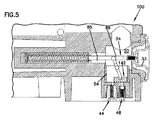
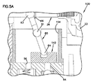
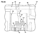
図5〜6Aに示す膜ポンプの実施形態
FIG. 1 shows a
Embodiment of the membrane pump shown in FIGS.
図5〜6Aは、本開示の原理を一体化したポンプ100の他の例を示している。ポンプ100は、図1〜4Aを参照して上に述べた実施形態と同じ多くの特徴を有する。ポンプ100は、レバー80で操作される異なった弁スプール142を有する。弁スプール142は、膜のロッド34から離隔したスプール穴154に配置されている。弁スプール142は、膜のロッド34および膜33の移動方向に平行な方向に移動できる。レバー80は、弁スプール142を操作できるように膜のロッド34に連結する。レバー80は、支点81,第1接続83および第2接続84を有する。レバー80は、支点81の周りに回動する。第1接続83は、膜のロッド34に連結され、第2接続84は、弁スプール142に連結される。第1接続83は、膜のロッド34上でレバー80のスライド係合を提供する。膜のロッド34に沿うレバー80の行程距離を制御するために、一対の第1ストッパ85と第2ストッパ86が膜のロッド34に沿って設けられている。
5-6A illustrate another example of a
第1,第2ストッパ85,86の間の空間は、ポンプ10の定常状態動作の間、輸送室20内に充填過剰または充填不足の状態が生じるまで、弁スプール142を静止状態に維持する「滞留」を定義する。充填不足状態では、膜33は、輸送室20内の遙か後方へ移動し、第2ストッパ86がレバー80を支点81の周りに回動させて、アンダーフィル弁の開口56を開くように弁スプール142を前方へ移動させる。充填過剰状態では、膜33は、正常状態よりも前方へ移動し、第1ストッパ85がレバー80を支点81の周りに回動させて、オーバーフィル弁の開口64を開くように弁スプール142を後方へ移動させる。
The space between the first and
図1〜6Aに示した弁スプールは、多くの変更が可能である。一例として、弁スプールと関連するオーバーフィル弁およびアンダーフィル弁は、ポンプ内に単一片として載置される予組立品として一体化できる。他の例として、弁スプールは、膜および膜のロッドの移動方向に対して垂直な方向(または平行でない任意の方向)に移動するよう配置できる。さらに、弁スプールは、膜のロッドの側部に横方向に、あるいは図1〜6Aに示す膜のロッドの鉛直下方と異なり膜のロッドの鉛直上方に配置することができる。
更なる考察
Many variations of the valve spool shown in FIGS. 1-6A are possible. As an example, the overfill and underfill valves associated with the valve spool can be integrated as a preassembly that is mounted as a single piece within the pump. As another example, the valve spool can be arranged to move in a direction perpendicular to the direction of movement of the membrane and the rod of the membrane (or any direction that is not parallel). Furthermore, the valve spool can be arranged laterally on the side of the membrane rod or vertically above the membrane rod, unlike the membrane rod vertically shown in FIGS.
Further consideration
上記実施形態を参照して述べた弁スプールは、膜の背後の輸送室に適正な量の作動油がある限り、静止位置を維持する。弁スプールは、膜が完全に伸張した位置と完全に後退した位置との間であれば膜の位置に拘わらずこの静止位置を維持する。静止位置にある弁スプールは、輸送室と油タンクの間にあるチェック弁の開口を閉ざす。従って、充填過剰または充填不足が生じた場合だけ、弁スプールが一方または他方のチェック弁の開口を開くように移動して、チェック弁が働くのである。リリーフ弁の制限された動作は、各ピストン行程の上死点または下死点で作動するので、圧力に基づく制御システムに幾らかの利点を提供する。しかし、チェック弁が作動すればするほど、チェック弁の摩耗感受性は増大する。 The valve spool described with reference to the above embodiment maintains a rest position as long as there is a proper amount of hydraulic fluid in the transport chamber behind the membrane. The valve spool maintains this rest position regardless of the position of the membrane as long as the membrane is between a fully extended position and a fully retracted position. The valve spool in the rest position closes the check valve opening between the transport chamber and the oil tank. Therefore, only when the overfill or underfill occurs, the valve spool moves so as to open the opening of one or the other check valve, and the check valve works. The limited operation of the relief valve provides some advantage for a pressure based control system since it operates at the top or bottom dead center of each piston stroke. However, the more the check valve is activated, the greater the wear sensitivity of the check valve.
上記実施形態のポンプの他の利点は、ポンプの充填過剰と充填不足を共に修正するに必要な部材数に関する。圧力に基づくシステムは、一般に、充填過剰と充填不足に対して別々の構成部材を必要とする。これに対して、上記実施形態のポンプは、充填過剰と充填不足を修正するため単一のスプール部材(弁スプール)を用いている。さらに、この弁スプールは、充填過剰状態または充填不足状態が生じた場合だけ作動するので,使用頻度および摩耗を受けることが少ない比較的簡素な一対のチェック弁と相俟って機能する。弁スプールの限定された動きが、摩耗を制限し、起こり得るメインテナンスを低減するのである。
結論
Another advantage of the pump of the above embodiment relates to the number of parts required to correct both overfilling and underfilling of the pump. Pressure based systems generally require separate components for overfill and underfill. On the other hand, the pump of the above embodiment uses a single spool member (valve spool) to correct overfilling and underfilling. Furthermore, the valve spool operates only when an overfill condition or underfill condition occurs, and thus functions in combination with a relatively simple pair of check valves that are less susceptible to usage and wear. The limited movement of the valve spool limits wear and reduces possible maintenance.
Conclusion
本開示の一態様は、膜,ポンプ室,輸送室,第1弁と第2弁,油タンクおよび弁スプールを備えた膜ポンプに関する。膜は、第1軸に沿って第1位置と第2位置の間を移動できる。ポンプ室は、膜の一方側に区画されてポンピングすべき流体を収容する。輸送室は、膜の他方側に区画されて作動油で満たされる。第1弁と第2弁は、チェック弁で構成される。油タンクは第1弁および第2弁を介して輸送室と連通する。弁スプールは、輸送室内に配置され、第1弁および第2弁を通る作動油の流れを制御する。弁スプールは、第1軸と異なる第2軸に沿って第1弁および第2弁の開口に対して複数の位置の間で移動できる。 One aspect of the present disclosure relates to a membrane pump including a membrane, a pump chamber, a transport chamber, first and second valves, an oil tank, and a valve spool. The membrane can move between a first position and a second position along a first axis. The pump chamber is defined on one side of the membrane and contains the fluid to be pumped. The transport chamber is partitioned on the other side of the membrane and filled with hydraulic oil. The first valve and the second valve are constituted by check valves. The oil tank communicates with the transport chamber via the first valve and the second valve. The valve spool is disposed in the transport chamber and controls the flow of hydraulic oil through the first valve and the second valve. The valve spool is movable between a plurality of positions relative to the opening of the first valve and the second valve along a second axis different from the first axis.
本開示の他の態様は、膜,ピストン,輸送室,油タンクおよびスプール部材を備えた作動油で駆動されるポンプに関する。膜は、第1軸の周りに移動できる。輸送室は、膜とピストンの間に区画されて作動油で満たされる。油タンクは、少なくとも1つの弁を介して輸送室と連通する。スプール部材は、輸送室と油タンクの間の作動油の流れを制御する。スプール部材は、輸送室に充填過剰または充填不足状態が生じたとき、上記少なくとも1つの弁に対して動くことができる。スプール部材は、第1軸に対して同軸には配置されていない。 Another aspect of the present disclosure relates to a hydraulic oil driven pump comprising a membrane, piston, transport chamber, oil tank and spool member. The membrane can move around the first axis. The transport chamber is partitioned between the membrane and the piston and filled with hydraulic oil. The oil tank communicates with the transport chamber via at least one valve. The spool member controls the flow of hydraulic oil between the transport chamber and the oil tank. The spool member can move relative to the at least one valve when an overfill or underfill condition occurs in the transport chamber. The spool member is not arranged coaxially with respect to the first axis.
本開示の更なる態様は、作動油で駆動される膜ポンプ内の作動油の圧力を均衡させる方法に関する。膜ポンプは、膜,ピストン,膜とピストンの間に設けられた輸送室,油タンク,弁スプールおよび油タンクと輸送室の間を連通する少なくとも1つの弁を備える。この方法は、第1軸に沿って膜を移動させるべくピストンを動かすステップと、油タンクと輸送室の間の作動油の流れを制御すべく上記少なくとも1つの弁に対して弁スプールを動かすステップを有する。弁スプールは、第1軸とは同軸でない第2軸に沿って移動する。 A further aspect of the present disclosure relates to a method of balancing the pressure of hydraulic fluid in a hydraulic fluid driven membrane pump. The membrane pump includes a membrane, a piston, a transport chamber provided between the membrane and the piston, an oil tank, a valve spool, and at least one valve that communicates between the oil tank and the transport chamber. The method includes moving a piston to move the membrane along a first axis and moving a valve spool relative to the at least one valve to control hydraulic fluid flow between the oil tank and the transfer chamber. Have The valve spool moves along a second axis that is not coaxial with the first axis.
上述の詳細な説明では、開示を能率化するため、種々の特徴を折々一緒に組にして単一の実施形態とした。本開示の方法は、発明の主題のクレームされた実施形態が各請求項に明白に記載された以上の特徴を要求するという意図を反映していると解釈されてはならない。むしろ、次の請求項は、開示された単一の実施形態の総ての特徴よりも少ない事項に発明の主題が存することを反映していると解釈されるべきである。従って、次の請求項は発明の詳細な説明に統合されていて、各請求項は、別々の好ましい実施形態として独立している。従って、請求項の神髄と範囲は、ここに述べた好ましい実施形態に限定されてはならない。 In the foregoing detailed description, various features have been combined from time to time to form a single embodiment in order to streamline the disclosure. This method of disclosure is not to be interpreted as reflecting an intention that the claimed embodiments of the inventive subject matter require more features than are expressly recited in each claim. Rather, the following claims should be construed to reflect the subject matter of the invention in less than all features of a single disclosed embodiment. Thus, the following claims are incorporated into the detailed description of the invention, with each claim standing on its own as a separate preferred embodiment. Therefore, the spirit and scope of the claims should not be limited to the preferred embodiments described herein.
Claims (12)
この膜の第1の側にあって、ポンピングされる流体を収容するようになっているポンプ室と、
ピストンと、
上記膜の第2の側にあって、この膜と上記ピストンの間に区画され、作動油で満たされる輸送室を備えた膜ポンプにおいて、
第1および第2の一方向弁と、
上記第1の一方向弁と油タンクに直接導く第1の流路および上記第2の一方向弁と油タンクから輸送室へ直接延びる第2の流路を介して上記輸送室に連通する油タンクと、
上記第1および第2の一方向弁を通る作動油の流れを制御すべく上記輸送室内に設けられ、上記第1および第2の一方向弁の開口に対して複数の位置の間を上記第1軸とは異なる第2軸に沿って移動できる弁スプールを備えた膜ポンプ。 A membrane capable of moving along a first axis between a first position and a second position;
A pump chamber on a first side of the membrane and adapted to contain the fluid to be pumped;
A piston,
In a membrane pump with a transport chamber on the second side of the membrane, partitioned between the membrane and the piston and filled with hydraulic oil,
First and second one-way valves;
Oil communicating with the transport chamber via the first one-way valve directly leading to the oil tank and the second one-way valve directly extending from the oil tank to the transport chamber. A tank,
Provided in the transport chamber to control the flow of hydraulic fluid through the first and second one-way valves, and the first and second one-way valves are positioned between a plurality of positions with respect to the openings. A membrane pump having a valve spool that can move along a second axis different from the one axis.
上記方法は、
上記膜を第1軸に沿って動かすべく上記ピストンを移動させるステップと、
上記油タンクと輸送室の間の作動油の流れを制御すべく上記第1の一方向弁と第2の一方向弁に対して上記弁スプールを移動させるステップとを備え、上記弁スプールは、上記第1軸と同軸でない第2軸に沿って移動する方法。 In the method of balancing the pressure of hydraulic fluid in a membrane pump driven by hydraulic fluid, the membrane pump includes a membrane, a piston, a transport chamber provided between the membrane and the piston, an oil tank, and a valve. A spool, a first one-way valve, a first flow path for flowing hydraulic oil directly from the transport chamber to the oil tank, a second one-way valve, and a flow of hydraulic oil directly from the oil tank to the transport chamber A second flow path,
The above method
Moving the piston to move the membrane along a first axis;
Moving the valve spool relative to the first one-way valve and the second one-way valve to control the flow of hydraulic oil between the oil tank and the transport chamber, the valve spool comprising: A method of moving along a second axis that is not coaxial with the first axis.
Applications Claiming Priority (3)
| Application Number | Priority Date | Filing Date | Title |
|---|---|---|---|
| US11/743,505 | 2007-05-02 | ||
| US11/743,505 US7665974B2 (en) | 2007-05-02 | 2007-05-02 | Diaphragm pump position control with offset valve axis |
| PCT/US2008/062169 WO2008137515A1 (en) | 2007-05-02 | 2008-05-01 | Diaphragm pump position control with offset valve axis |
Publications (2)
| Publication Number | Publication Date |
|---|---|
| JP2010526239A JP2010526239A (en) | 2010-07-29 |
| JP5259695B2 true JP5259695B2 (en) | 2013-08-07 |
Family
ID=39619136
Family Applications (1)
| Application Number | Title | Priority Date | Filing Date |
|---|---|---|---|
| JP2010506632A Active JP5259695B2 (en) | 2007-05-02 | 2008-05-01 | Membrane pump position control by offset valve shaft |
Country Status (11)
| Country | Link |
|---|---|
| US (1) | US7665974B2 (en) |
| EP (1) | EP2145109B1 (en) |
| JP (1) | JP5259695B2 (en) |
| KR (1) | KR101401213B1 (en) |
| CN (1) | CN101743403B (en) |
| BR (1) | BRPI0811471B1 (en) |
| DK (1) | DK2145109T3 (en) |
| EA (1) | EA016439B1 (en) |
| ES (1) | ES2632131T3 (en) |
| PL (1) | PL2145109T3 (en) |
| WO (1) | WO2008137515A1 (en) |
Families Citing this family (27)
| Publication number | Priority date | Publication date | Assignee | Title |
|---|---|---|---|---|
| TW201024526A (en) * | 2008-12-23 | 2010-07-01 | Cheng-Chin Kung | Cooling and circulating system for engine oil |
| WO2011005571A2 (en) * | 2009-06-23 | 2011-01-13 | Weir Spm, Inc. | Readily removable pump crosshead |
| US20100325888A1 (en) * | 2009-06-30 | 2010-12-30 | Weir Spm, Inc. | Carrier for plunger during disassembly |
| US9157468B2 (en) | 2010-06-04 | 2015-10-13 | S.P.M. Flow Control, Inc. | Packing nut lock and method of use |
| DE102010039831B4 (en) * | 2010-08-26 | 2022-02-03 | Prominent Gmbh | Diaphragm pump and method for adjusting such |
| AU2011343526A1 (en) | 2010-12-16 | 2013-07-11 | S.P.M. Flow Control, Inc. | Plunger packing with wedge seal having extrusion recess |
| CN104204524A (en) | 2012-02-03 | 2014-12-10 | S.P.M.流量控制股份有限公司 | Pump assembly including fluid cylinder and tapered valve seats |
| USD748228S1 (en) | 2013-01-31 | 2016-01-26 | S.P.M. Flow Control, Inc. | Valve seat |
| DE102012106848A1 (en) * | 2012-07-27 | 2014-01-30 | Prominent Dosiertechnik Gmbh | Dosing system and metering pump for this |
| USD726224S1 (en) | 2013-03-15 | 2015-04-07 | S.P.M. Flow Control, Inc. | Plunger pump thru rod |
| US8707853B1 (en) | 2013-03-15 | 2014-04-29 | S.P.M. Flow Control, Inc. | Reciprocating pump assembly |
| DE102013105072A1 (en) | 2013-05-16 | 2014-11-20 | Prominent Gmbh | Diaphragm pump with position control |
| US9845794B2 (en) * | 2013-10-08 | 2017-12-19 | Ingersoll-Rand Company | Hydraulically actuated diaphragm pumps |
| FR3021713B1 (en) * | 2014-05-27 | 2019-04-05 | Milton Roy Europe | HYDRAULICALLY CONTROLLED MEMBRANE PUMP COMPRISING A DEDICATED DEGASSAGE PATH |
| WO2015200810A2 (en) | 2014-06-27 | 2015-12-30 | S.P.M. Flow Control, Inc. | Pump drivetrain damper system and control systems and methods for same |
| BR112017001351A2 (en) | 2014-07-25 | 2017-11-14 | Spm Flow Control Inc | and method for mounting a set of alternative pumps. |
| US9964106B2 (en) * | 2014-11-04 | 2018-05-08 | Wanner Engineering, Inc. | Diaphragm pump with dual spring overfill limiter |
| CA2972031C (en) | 2014-12-22 | 2020-01-07 | S.P.M. Flow Control, Inc. | Reciprocating pump with dual circuit power end lubrication system |
| US10221848B2 (en) | 2015-07-02 | 2019-03-05 | S.P.M. Flow Control, Inc. | Valve for reciprocating pump assembly |
| US11448210B2 (en) | 2015-07-02 | 2022-09-20 | Spm Oil & Gas Inc. | Valve for reciprocating pump assembly |
| ITUB20151971A1 (en) * | 2015-07-06 | 2017-01-06 | Seko Spa | MEMBRANE PUMP |
| USD759728S1 (en) | 2015-07-24 | 2016-06-21 | S.P.M. Flow Control, Inc. | Power end frame segment |
| US10436766B1 (en) | 2015-10-12 | 2019-10-08 | S.P.M. Flow Control, Inc. | Monitoring lubricant in hydraulic fracturing pump system |
| DE102016114680A1 (en) * | 2016-08-08 | 2018-02-08 | Prominent Gmbh | Device for generating a pulsating hydraulic fluid pressure |
| RU175658U1 (en) * | 2017-08-10 | 2017-12-13 | Общество с ограниченной ответственностью "Купер" | PLUNGER-DIAPHRAGM PUMP |
| DE102018111601B4 (en) * | 2018-05-15 | 2020-09-24 | Prominent Gmbh | Membrane system control with magnetically held locking element |
| WO2023191913A1 (en) | 2022-03-28 | 2023-10-05 | Wanner Engineering, Inc. | Diaphragm position control system |
Family Cites Families (24)
| Publication number | Priority date | Publication date | Assignee | Title |
|---|---|---|---|---|
| US1920014A (en) * | 1931-06-26 | 1933-07-25 | Trico Products Corp | Multiple diaphragm pump |
| US2679209A (en) * | 1949-09-01 | 1954-05-25 | Arthur Bachert | Pumping apparatus |
| US2919650A (en) * | 1955-09-22 | 1960-01-05 | Reiners Walter | Diaphragm pump for non-lubricating and chemically aggressive liquids |
| US3769879A (en) * | 1971-12-09 | 1973-11-06 | A Lofquist | Self-compensating diaphragm pump |
| US3884598A (en) * | 1973-10-05 | 1975-05-20 | Wanner Engineering | Piston assembly for diaphragm pump |
| USRE31932E (en) * | 1975-06-30 | 1985-07-02 | Diaphragm assembly for the demand regulator of a breathing apparatus | |
| US4050859A (en) * | 1976-07-01 | 1977-09-27 | Graco Inc. | Diaphragm pump having a reed valve barrier to hydraulic shock in the pressurizing fluid |
| FR2492473B1 (en) * | 1980-10-17 | 1985-06-28 | Milton Roy Dosapro | COMPENSATION MEMBRANE PUMP IN THE HYDRAULIC CONTROL CHAMBER |
| US4381180A (en) * | 1981-07-13 | 1983-04-26 | Sell John R | Double diaphragm pump with controlling slide valve and adjustable stroke |
| US4474540A (en) * | 1982-09-10 | 1984-10-02 | Pennwalt Corporation | Tubular diaphragm pump |
| FR2557928B1 (en) * | 1984-01-11 | 1988-04-22 | Milton Roy Dosapro | IMPROVEMENT ON VARIABLE FLOW MEMBRANE PUMPS. |
| DE3446914A1 (en) * | 1984-12-21 | 1986-07-03 | Ott Kg Lewa | DIAPHRAGM PUMP WITH HYDRAULICALLY DRIVED ROLLER |
| DE3708868A1 (en) * | 1987-03-18 | 1988-10-06 | Ott Kg Lewa | METHOD AND DEVICE FOR STARTING A HYDRAULIC DIAPHRAGM PUMP AGAINST LOAD |
| WO1991011616A1 (en) | 1990-02-01 | 1991-08-08 | Wanner Engineering, Inc. | Improved system for pumping fluid |
| JP2509746Y2 (en) * | 1990-10-31 | 1996-09-04 | トリニティ工業株式会社 | Diaphragm pump |
| DE4141670C2 (en) * | 1991-12-17 | 1994-09-29 | Ott Kg Lewa | Hydraulically driven diaphragm pump with diaphragm stroke limitation |
| US5326234A (en) * | 1993-02-17 | 1994-07-05 | Versa-Matic Tool, Inc. | Fluid driven pump |
| US5647733A (en) * | 1995-12-01 | 1997-07-15 | Pulsafeeder Inc. | Diaphragm metering pump having modular construction |
| US6071089A (en) * | 1998-02-20 | 2000-06-06 | General Motors Corporation | Hydraulic diaphragm pump |
| US6722256B2 (en) | 2002-09-12 | 2004-04-20 | Ingersoll-Rand Company | Reduced icing valves and gas-driven motor and diaphragm pump incorporating same |
| US6899530B2 (en) * | 2002-10-31 | 2005-05-31 | Wanner Engineering, Inc. | Diaphragm pump with a transfer chamber vent with a longitudinal notch on the piston cylinder |
| US7090474B2 (en) * | 2003-05-16 | 2006-08-15 | Wanner Engineering, Inc. | Diaphragm pump with overfill limiter |
| US7063517B2 (en) * | 2004-06-16 | 2006-06-20 | Ingersoll-Rand Company | Valve apparatus and pneumatically driven diaphragm pump incorporating same |
| US7425120B2 (en) * | 2005-04-26 | 2008-09-16 | Wanner Engineering, Inc. | Diaphragm position control for hydraulically driven pumps |
-
2007
- 2007-05-02 US US11/743,505 patent/US7665974B2/en active Active
-
2008
- 2008-05-01 CN CN2008800185693A patent/CN101743403B/en active Active
- 2008-05-01 PL PL08747303T patent/PL2145109T3/en unknown
- 2008-05-01 KR KR1020097025154A patent/KR101401213B1/en active IP Right Grant
- 2008-05-01 JP JP2010506632A patent/JP5259695B2/en active Active
- 2008-05-01 WO PCT/US2008/062169 patent/WO2008137515A1/en active Application Filing
- 2008-05-01 DK DK08747303.9T patent/DK2145109T3/en active
- 2008-05-01 EA EA200901475A patent/EA016439B1/en unknown
- 2008-05-01 EP EP08747303.9A patent/EP2145109B1/en active Active
- 2008-05-01 BR BRPI0811471-4A patent/BRPI0811471B1/en active IP Right Grant
- 2008-05-01 ES ES08747303.9T patent/ES2632131T3/en active Active
Also Published As
| Publication number | Publication date |
|---|---|
| BRPI0811471A2 (en) | 2014-11-18 |
| DK2145109T3 (en) | 2017-06-19 |
| ES2632131T3 (en) | 2017-09-11 |
| EA016439B1 (en) | 2012-05-30 |
| EP2145109B1 (en) | 2017-04-05 |
| CN101743403B (en) | 2012-08-29 |
| KR20100022966A (en) | 2010-03-03 |
| EP2145109A1 (en) | 2010-01-20 |
| CN101743403A (en) | 2010-06-16 |
| WO2008137515A1 (en) | 2008-11-13 |
| JP2010526239A (en) | 2010-07-29 |
| EA200901475A1 (en) | 2010-04-30 |
| US7665974B2 (en) | 2010-02-23 |
| BRPI0811471B1 (en) | 2019-10-01 |
| PL2145109T3 (en) | 2017-11-30 |
| US20080273997A1 (en) | 2008-11-06 |
| KR101401213B1 (en) | 2014-05-28 |
Similar Documents
| Publication | Publication Date | Title |
|---|---|---|
| JP5259695B2 (en) | Membrane pump position control by offset valve shaft | |
| US7425120B2 (en) | Diaphragm position control for hydraulically driven pumps | |
| US8430081B2 (en) | Direct-injection system fuel pump with a maximum-pressure valve | |
| KR101945556B1 (en) | Reciprocating pump valve assembly with thermal relief | |
| RU2573069C2 (en) | Membrane pump provided with leaks compensation inertial-control valve | |
| JP7398457B2 (en) | Inlet control valve for high pressure fuel pump | |
| RU2349795C2 (en) | Diaphragm pump (versions) | |
| US20130287600A1 (en) | Direct Volume-Controlling Device (DVCD) for Reciprocating Positive-Displacement Pumps | |
| US11085581B2 (en) | Lubricating-grease pump and method for recovery of leakage grease of a lubricating-grease pump | |
| CA3070881A1 (en) | Hydraulic diaphragm control using a solenoid valve | |
| US9964105B2 (en) | Diaphragm pump having position control | |
| KR100874205B1 (en) | Diaphragm type reciprocating pump | |
| JP7446298B2 (en) | High pressure fuel pump with mechanical pressure regulation | |
| KR101068025B1 (en) | Fluid pump | |
| JP2013136990A (en) | Fuel pressure control device and fuel supply device using the same device | |
| SA08290607B1 (en) | Diaphragm Pump Position Control with Offset Valve Axis | |
| JP2016148293A (en) | High pressure pump | |
| JP2006057537A (en) | High pressure fuel pump |
Legal Events
| Date | Code | Title | Description |
|---|---|---|---|
| A621 | Written request for application examination |
Free format text: JAPANESE INTERMEDIATE CODE: A621 Effective date: 20110425 |
|
| A977 | Report on retrieval |
Free format text: JAPANESE INTERMEDIATE CODE: A971007 Effective date: 20121116 |
|
| A131 | Notification of reasons for refusal |
Free format text: JAPANESE INTERMEDIATE CODE: A131 Effective date: 20121127 |
|
| A521 | Request for written amendment filed |
Free format text: JAPANESE INTERMEDIATE CODE: A523 Effective date: 20130226 |
|
| TRDD | Decision of grant or rejection written | ||
| A01 | Written decision to grant a patent or to grant a registration (utility model) |
Free format text: JAPANESE INTERMEDIATE CODE: A01 Effective date: 20130326 |
|
| A61 | First payment of annual fees (during grant procedure) |
Free format text: JAPANESE INTERMEDIATE CODE: A61 Effective date: 20130424 |
|
| FPAY | Renewal fee payment (event date is renewal date of database) |
Free format text: PAYMENT UNTIL: 20160502 Year of fee payment: 3 |
|
| R150 | Certificate of patent or registration of utility model |
Ref document number: 5259695 Country of ref document: JP Free format text: JAPANESE INTERMEDIATE CODE: R150 Free format text: JAPANESE INTERMEDIATE CODE: R150 |
|
| R250 | Receipt of annual fees |
Free format text: JAPANESE INTERMEDIATE CODE: R250 |
|
| R250 | Receipt of annual fees |
Free format text: JAPANESE INTERMEDIATE CODE: R250 |
|
| R250 | Receipt of annual fees |
Free format text: JAPANESE INTERMEDIATE CODE: R250 |
|
| R250 | Receipt of annual fees |
Free format text: JAPANESE INTERMEDIATE CODE: R250 |
|
| R250 | Receipt of annual fees |
Free format text: JAPANESE INTERMEDIATE CODE: R250 |
|
| R250 | Receipt of annual fees |
Free format text: JAPANESE INTERMEDIATE CODE: R250 |
|
| R250 | Receipt of annual fees |
Free format text: JAPANESE INTERMEDIATE CODE: R250 |
|
| R250 | Receipt of annual fees |
Free format text: JAPANESE INTERMEDIATE CODE: R250 |