JP5259643B2 - Chain guide mechanism - Google Patents
Chain guide mechanism Download PDFInfo
- Publication number
- JP5259643B2 JP5259643B2 JP2010090663A JP2010090663A JP5259643B2 JP 5259643 B2 JP5259643 B2 JP 5259643B2 JP 2010090663 A JP2010090663 A JP 2010090663A JP 2010090663 A JP2010090663 A JP 2010090663A JP 5259643 B2 JP5259643 B2 JP 5259643B2
- Authority
- JP
- Japan
- Prior art keywords
- guide
- chain
- sprocket
- bridge
- chain guide
- Prior art date
- Legal status (The legal status is an assumption and is not a legal conclusion. Google has not performed a legal analysis and makes no representation as to the accuracy of the status listed.)
- Expired - Fee Related
Links
- 239000010687 lubricating oil Substances 0.000 claims description 50
- 238000003825 pressing Methods 0.000 claims description 21
- 238000012423 maintenance Methods 0.000 description 12
- 230000000694 effects Effects 0.000 description 10
- 239000000463 material Substances 0.000 description 8
- 230000003014 reinforcing effect Effects 0.000 description 7
- 230000002265 prevention Effects 0.000 description 6
- 229920005989 resin Polymers 0.000 description 4
- 239000011347 resin Substances 0.000 description 4
- 238000005461 lubrication Methods 0.000 description 2
- 238000000926 separation method Methods 0.000 description 2
- 239000000725 suspension Substances 0.000 description 2
- 229920003189 Nylon 4,6 Polymers 0.000 description 1
- 229920002292 Nylon 6 Polymers 0.000 description 1
- 229920002302 Nylon 6,6 Polymers 0.000 description 1
- 229930182556 Polyacetal Natural products 0.000 description 1
- 230000015572 biosynthetic process Effects 0.000 description 1
- 239000012141 concentrate Substances 0.000 description 1
- 230000017525 heat dissipation Effects 0.000 description 1
- 238000004519 manufacturing process Methods 0.000 description 1
- 238000000034 method Methods 0.000 description 1
- 238000000465 moulding Methods 0.000 description 1
- 239000003921 oil Substances 0.000 description 1
- 230000002093 peripheral effect Effects 0.000 description 1
- 229920006324 polyoxymethylene Polymers 0.000 description 1
- 229920003002 synthetic resin Polymers 0.000 description 1
- 239000000057 synthetic resin Substances 0.000 description 1
- 230000008719 thickening Effects 0.000 description 1
Images

Landscapes
- Devices For Conveying Motion By Means Of Endless Flexible Members (AREA)
Description
本発明は、チェーンを摺動案内する複数のチェーンガイドと、該複数のチェーンガイドを一体に保持するガイドブリッジからなるチェーンガイド機構に関し、例えば、エンジンルーム内のクランク軸とカム軸の夫々に設けたスプロケット間に無端懸回したサイレントチェーン、ローラチェーン等のタイミングチェーンをチェーンガイドによって張力保持、摺動案内を行うエンジンのタイミングシステムに好適なチェーンガイド機構に関するものである。 The present invention relates to a chain guide mechanism including a plurality of chain guides for slidingly guiding a chain and a guide bridge for integrally holding the plurality of chain guides. For example, the present invention is provided on each of a crankshaft and a camshaft in an engine room. The present invention relates to a chain guide mechanism suitable for an engine timing system in which a timing chain such as a silent chain or a roller chain suspended endlessly between sprockets is held and tensioned by a chain guide.
従来周知のエンジンのタイミングシステムは、図12に示すように、エンジンルーム内のクランク軸に取付けた駆動スプロケットS1とカム軸に取付けた一対の従動スプロケットS2、S3間にタイミングチェーンCが無端懸回されてなり、タイミングチェーンCのテンショナTの押圧力で張力を適正に保持してチェーンをガイドする揺動チェーンガイド520とタイミングチェーンCの走行を案内する固定チェーンガイド530とによってチェーンガイド機構が構成されている。
As shown in FIG. 12, a conventionally known engine timing system has an endless suspension of a timing chain C between a drive sprocket S1 attached to a crankshaft in an engine room and a pair of driven sprockets S2 and S3 attached to a camshaft. Thus, the chain guide mechanism is constituted by the
このチェーンガイド機構では、揺動チェーンガイド520はエンジンルーム(図示せず)に取付軸Bで揺動自在に取付けられ、固定チェーンガイド530はエンジンルームに取付軸B1、B2で固定されるため、組立やメンテナンス時に、駆動スプロケットS1、従動スプロケットS2、S3、揺動チェーンガイド520、固定チェーンガイド530の組み付け、取り外しやタイミングチェーンCの懸回、取り外しをそれぞれ夫々個別に行う必要があり、作業性が悪いという問題があった。
In this chain guide mechanism, the
このような問題を軽減するため、揺動チェーンガイドと固定チェーンガイドを一体に保持し、組立やメンテナンス時の作業性を向上したチェーンガイド機構を採用したタイミングシステムが公知である。 In order to alleviate such a problem, a timing system that employs a chain guide mechanism in which a swinging chain guide and a fixed chain guide are integrally held to improve workability during assembly and maintenance is known.
この公知のタイミングシステムのチェーンガイド機構600は、図13に示すように、固定チェーンガイド630がガイドブリッジ610と一体に形成され、ガイドブリッジ610の先端部のガイド取付孔612が揺動チェーンガイド620の揺動支点である取付ボス部621に嵌合されて一体に保持されるように構成されている。
In the
また、この公知のタイミングシステムのチェーンガイド機構600は、ガイドブリッジ610が、駆動スプロケットS1、従動スプロケットS2、S3、揺動チェーンガイド620の相対位置を規定する形状に形成されており、組み付け前に仮組立体とすることで、組立やメンテナンス時の相対位置合わせを不要としている(例えば、特許文献1参照。)。
Further, the
しかしながら、前記公知のチェーンガイド機構600は、揺動チェーンガイド620と固定チェーンガイド630は一体に保持されるが、駆動スプロケットS1、従動スプロケットS2、S3やタイミングチェーンCは相対位置関係が規定されるだけで、一体に保持されるものではないため、組立やメンテナンス時の作業性の向上はごく僅かであるという問題があった。
However, in the known
また、固定チェーンガイド630と一体に形成されたガイドブリッジ610が、タイミングチェーンCの一側面側にのみに揺動チェーンガイド620の取付ボス部621まで伸びるように設けられているため、図14に示すように、ガイドブリッジ610が厚み方向に変形して、ガイド取付孔612と揺動チェーンガイド620の取付ボス部621とが離脱しやすいという問題があった。
また、ガイドブリッジ610によって、スプロケットS1に供給される潤滑油の流動が妨げられるという問題があった。
Further, since the
In addition, the
本発明は、前述したような従来技術の問題を解決するものであって、すなわち、本発明の目的は、簡単な構成で複数のチェーンガイド、チェーンおよびスプロケットを一体保持可能とし、組立やメンテナンス時の作業性を向上するとともに、スプロケットに充分に潤滑油を供給するチェーンガイド機構を提供することである。 The present invention solves the problems of the prior art as described above. That is, the object of the present invention is to make it possible to integrally hold a plurality of chain guides, chains and sprockets with a simple configuration, during assembly and maintenance. It is to provide a chain guide mechanism that sufficiently improves the workability and supplies sufficient lubricating oil to the sprocket.
本請求項1に係る発明は、チェーンを摺動案内する複数のチェーンガイドと、該複数のチェーンガイドを一体に保持するガイドブリッジからなるチェーンガイド機構において、前記チェーンガイドが、円筒状の取付ボス部を備え、前記ガイドブリッジが、前記複数のチェーンガイドを両端に保持するアーム部と、該アーム部の中間に設けられた基部とを有し、前記ガイドブリッジのアーム部が、前記基部から両端に向かって前記チェーンガイドの両側面を挟むようにそれぞれ対になって延びるとともに、前記チェーンガイドの取付ボス部を嵌合保持するガイド取付孔を有し、前記基部が、前記アーム部の中間部から略T字状に延び、その先端部にスプロケットに摺接するスプロケット押え部を有し、該スプロケット押え部が、中央にスプロケット歯の通過を許容する溝部を有しているとともに、該溝部の両側にスプロケットのボス部と摺接可能な摺接部を有し、前記ガイドブリッジが、前記アーム部の各ガイド取付孔から前記基部のスプロケット押え部の溝部に至る潤滑油通路を有していることにより、前記課題を解決するものである。
The invention according to
本請求項2に係る発明は、請求項1に記載されたチェーンガイド機構の構成に加えて、前記潤滑油通路が、前記ガイドブリッジのアーム部において、その対向内面側に溝状に形成されていることにより、前記課題を解決するものである。 According to the second aspect of the present invention, in addition to the structure of the chain guide mechanism described in the first aspect, the lubricating oil passage is formed in a groove shape on the opposite inner surface side of the arm portion of the guide bridge. Therefore, the above-described problem is solved.
本請求項3に係る発明は、請求項1または請求項2に記載されたチェーンガイド機構の構成に加えて、前記チェーンガイドの一方が、円筒状の取付ボス部の外周に係合突起を備え、前記ガイドブリッジのガイド取付孔の少なくとも一つが、前記係合突起と係合する切り欠きを有し、前記潤滑油通路が、該ガイド取付孔の切り欠きの先端部から延びていることにより、前記課題を解決するものである。 According to the third aspect of the present invention, in addition to the structure of the chain guide mechanism according to the first or second aspect, one of the chain guides includes an engagement protrusion on the outer periphery of the cylindrical mounting boss portion. And at least one of the guide mounting holes of the guide bridge has a notch that engages with the engaging protrusion, and the lubricating oil passage extends from the tip of the notch of the guide mounting hole. The problem is solved.
本請求項4に係る発明は、請求項1乃至請求項3のいずれかに記載されたチェーンガイド機構の構成に加えて、前記潤滑油通路が、前記ガイドブリッジの基部において、そのチェーン通過側表面に溝状に形成されていることにより、前記課題を解決するものである。
In the invention according to claim 4, in addition to the structure of the chain guide mechanism according to any one of
本請求項5に係る発明は、請求項1乃至請求項4のいずれかに記載されたチェーンガイド機構の構成に加えて、前記ガイドブリッジの基部が、前記アーム部側の先端をV字状に形成され、前記潤滑油通路が、該V字状の先端からスプロケット押え部の溝部に至る経路を有していることにより、前記課題をさらに解決するものである。 According to the fifth aspect of the present invention, in addition to the structure of the chain guide mechanism according to any one of the first to fourth aspects, the base portion of the guide bridge has a V-shaped tip on the arm portion side. The above-described problem is further solved by the formation of the lubricating oil passage having a path extending from the V-shaped tip to the groove of the sprocket pressing portion.
本請求項6に係る発明は、請求項5のいずれかに記載されたチェーンガイド機構の構成に加えて、前記V字状の切込み部から先端からスプロケット押え部の溝部に至る経路が、前記ガイドブリッジの基部に設けられた貫通孔であることにより、前記課題をさらに解決するものである。 In the invention according to claim 6, in addition to the structure of the chain guide mechanism according to any one of claims 5, a path from the V-shaped cut portion to the groove portion of the sprocket pressing portion from the tip end is formed on the guide. By the through hole provided in the base of the bridge, the above problem is further solved.
本請求項7に係る発明は、請求項1乃至請求項6のいずれかに記載されたチェーンガイド機構の構成に加えて、前記複数のチェーンガイドが、前記ガイドブリッジの潤滑油通路に向けての潤滑油の流動を促す切り欠き溝を有するリブで補強されていることにより、前記課題をさらに解決するものである。 According to the seventh aspect of the invention, in addition to the structure of the chain guide mechanism according to any one of the first to sixth aspects, the plurality of chain guides are directed toward the lubricating oil passage of the guide bridge. The problem is further solved by being reinforced with a rib having a notch groove that promotes the flow of the lubricating oil.
本請求項1に係る発明のチェーンガイド機構は、チェーンを摺動案内する複数のチェーンガイドと、該複数のチェーンガイドを一体に保持するガイドブリッジからなるチェーンガイド機構において、チェーンガイドが円筒状の取付ボス部を備え、ガイドブリッジが複数のチェーンガイドを両端に保持するアーム部と、該アーム部の中間に設けられた基部とを有し、ガイドブリッジのアーム部が基部から両端に向かってチェーンガイドの両側面を挟むようにそれぞれ対になって延びるとともに、チェーンガイドの取付ボス部を嵌合保持するガイド取付孔を有していることにより、複数のチェーンガイドがそれぞれ基部から延びる1対のアームに挟まれるように保持されるため、アーム部の長さが短くなり変形が少なくガイド取付孔と取付ボス部との離脱を防止することができ、確実に一体化されて組立やメンテナンス時の作業性を向上することができる。 The chain guide mechanism according to the first aspect of the present invention is a chain guide mechanism comprising a plurality of chain guides for slidingly guiding a chain and a guide bridge for integrally holding the plurality of chain guides. The guide bridge has an arm portion that holds a plurality of chain guides at both ends, and a base portion provided in the middle of the arm portion, and the arm portion of the guide bridge is chained from the base portion toward both ends. The pair of guides extend in pairs so as to sandwich both side surfaces of the guide, and have a guide mounting hole for fitting and holding the mounting boss portion of the chain guide, so that a plurality of chain guides each extend from the base portion. Since the arm is held so as to be sandwiched between the arms, the length of the arm is shortened, and there is little deformation. Guide mounting hole and mounting boss. It is possible to prevent the withdrawal, it can be securely integrated to improve the workability at the time of assembly and maintenance.
また、基部の両側方にできる、基部、チェーンガイドおよび1対のアーム部で囲まれた空間にあらかじめチェーンをセットしておくことで、複数のチェーンガイドとともにチェーンも一体に保持することができ、組立やメンテナンス時の作業性をさらに向上することができる。 In addition, by setting the chain in advance in the space surrounded by the base, chain guide and a pair of arm portions that can be formed on both sides of the base, the chain can be held together with a plurality of chain guides. The workability during assembly and maintenance can be further improved.
また、基部がアーム部の中間部から略T字状に延び、その先端部にスプロケットに摺接するスプロケット押え部を有し、該スプロケット押え部が、中央にスプロケット歯の通過を許容する溝部を有しているとともに、該溝部の両側にスプロケットのボス部と摺接可能な摺接部を有し、ガイドブリッジがアーム部の各ガイド取付孔から基部のスプロケット押え部の溝部に至る潤滑油通路を有していることにより、複数のチェーンガイドやガイドブリッジの表面を流下する潤滑油をスプロケットに集中するように誘導することができるため、スプロケットに充分に潤滑油を供給することができる。 In addition, the base portion has a substantially T-shape extending from the middle portion of the arm portion, and has a sprocket pressing portion that is in sliding contact with the sprocket at the tip thereof, and the sprocket pressing portion has a groove portion that allows passage of the sprocket teeth at the center. In addition, there are sliding contact portions that can slide in contact with the boss portion of the sprocket on both sides of the groove portion, and the guide bridge has a lubricating oil passage extending from each guide mounting hole of the arm portion to the groove portion of the base sprocket pressing portion. By having it, the lubricating oil flowing down the surfaces of the plurality of chain guides and guide bridges can be guided to concentrate on the sprocket, so that the lubricating oil can be sufficiently supplied to the sprocket.
本請求項2に係る発明のチェーンガイド機構は、請求項1に係るチェーンガイド機構が奏する効果に加えて、潤滑油通路が、ガイドブリッジのアーム部において、その対向内面側に溝状に形成されていることにより、複数のチェーンガイドから流下した潤滑油を、より効率良く基部側に誘導することができ、また、溝状に形成されることで潤滑油通路自体がガイドブリッジのアーム部を流下する潤滑油を集めることができ、さらにスプロケットに充分に潤滑油を供給することができる。 In the chain guide mechanism according to the second aspect of the present invention, in addition to the effect produced by the chain guide mechanism according to the first aspect, the lubricating oil passage is formed in a groove shape on the opposite inner surface side of the arm portion of the guide bridge. Therefore, the lubricating oil flowing down from the plurality of chain guides can be guided to the base side more efficiently, and the lubricating oil passage itself flows down the arm part of the guide bridge by being formed into a groove shape. The lubricating oil to be collected can be collected, and the lubricating oil can be sufficiently supplied to the sprocket.
本請求項3に係る発明のチェーンガイド機構は、請求項1または請求項2に係るチェーンガイド機構が奏する効果に加えて、チェーンガイドの一方が、円筒状の取付ボス部の外周に係合突起を備え、ガイドブリッジのガイド取付孔の少なくとも一つが、係合突起と係合する切り欠きを有し、潤滑油通路が、該ガイド取付孔の切り欠きの先端部から延びていることにより、チェーンガイドとガイドブリッジとの離脱を防止することができ、確実に一体化されて組立やメンテナンス時の作業性を向上することができるとともに、チェーンガイドから流下した潤滑油を、より効率良く基部側に誘導することができる。
In the chain guide mechanism of the invention according to
本請求項4に係る発明のチェーンガイド機構は、請求項1乃至請求項3のいずれかに係るチェーンガイド機構が奏する効果に加えて、潤滑油通路が、ガイドブリッジの基部において、そのチェーン通過側表面に溝状に形成されていることにより、チェーンガイドから流下しガイドブリッジのアーム部に沿って誘導された潤滑油を、より効率良くスプロケットに誘導することができる。 The chain guide mechanism according to the fourth aspect of the present invention has the effect that the chain guide mechanism according to any one of the first to third aspects exhibits the effect, and the lubricating oil passage is provided on the chain passing side at the base portion of the guide bridge. By forming the groove shape on the surface, the lubricating oil flowing down from the chain guide and guided along the arm portion of the guide bridge can be more efficiently guided to the sprocket.
本請求項5に係る発明のチェーンガイド機構は、請求項1乃至請求項4のいずれかに係るチェーンガイド機構が奏する効果に加えて、ガイドブリッジの基部が、アーム部側の先端をV字状に形成され、潤滑油通路が、該V字状の先端からスプロケット押え部の溝部に至る経路を有していることにより、ガイドブリッジの基部のアーム部側の先端で潤滑油を集めてスプロケットに誘導することができる。 In the chain guide mechanism according to the fifth aspect of the invention, in addition to the effect of the chain guide mechanism according to any one of the first to fourth aspects, the base portion of the guide bridge has a V-shaped tip on the arm side. And the lubricating oil passage has a path extending from the V-shaped tip to the groove of the sprocket retainer, so that the lubricating oil is collected at the tip of the arm portion side of the base portion of the guide bridge to the sprocket. Can be guided.
本請求項6に係る発明のチェーンガイド機構は、請求項5に係るチェーンガイド機構が奏する効果に加えて、V字状の切込み部から先端からスプロケット押え部の溝部に至る経路が、ガイドブリッジの基部に設けられた貫通孔であることにより、ガイドブリッジの基部のアーム部側の先端で集められた潤滑油を、より効率良くスプロケットに誘導することができる。 In the chain guide mechanism according to the sixth aspect of the present invention, in addition to the effect achieved by the chain guide mechanism according to the fifth aspect, the path from the V-shaped cut portion to the groove portion of the sprocket pressing portion extends from the tip to the groove portion of the sprocket holding portion. Due to the through hole provided in the base portion, the lubricating oil collected at the tip of the arm portion side of the base portion of the guide bridge can be more efficiently guided to the sprocket.
本請求項7に係る発明のチェーンガイド機構は、請求項1乃至請求項6のいずれかに係るチェーンガイド機構が奏する効果に加えて、複数のチェーンガイドが、ガイドブリッジの潤滑油通路に向けての潤滑油の流動を促す切り欠き溝を有するリブで補強されていることにより、チェーンガイドから流下する潤滑油をガイドブリッジのアーム部の各ガイド取付孔に向けて効率良く集めることができる。 In the chain guide mechanism according to the seventh aspect of the present invention, in addition to the effect of the chain guide mechanism according to any one of the first to sixth aspects, the plurality of chain guides are directed toward the lubricating oil passage of the guide bridge. By being reinforced with a rib having a notch groove that promotes the flow of the lubricating oil, the lubricating oil flowing down from the chain guide can be efficiently collected toward each guide mounting hole of the arm portion of the guide bridge.
本発明は、チェーンを摺動案内する複数のチェーンガイドと、該複数のチェーンガイドを一体に保持するガイドブリッジからなるチェーンガイド機構において、チェーンガイドが円筒状の取付ボス部を備え、ガイドブリッジが複数のチェーンガイドを両端に保持するアーム部と、該アーム部の中間に設けられた基部とを有し、ガイドブリッジのアーム部が基部から両端に向かってチェーンガイドの両側面を挟むようにそれぞれ対になって延びるとともに、チェーンガイドの取付ボス部を嵌合保持するガイド取付孔を有し、基部がアーム部の中間部から略T字状に延び、その先端部にスプロケットに摺接するスプロケット押え部を有し、該スプロケット押え部が、中央にスプロケット歯の通過を許容する溝部を有しているとともに、該溝部の両側にスプロケットのボス部と摺接可能な摺接部を有し、ガイドブリッジがアーム部の各ガイド取付孔から基部のスプロケット押え部の溝部に至る潤滑油通路を有しており、簡単な構成で複数のチェーンガイド、チェーンおよびスプロケットを一体保持可能とし、組立やメンテナンス時の作業性を向上するとともに、スプロケットに充分に潤滑油を供給するものであれば、その具体的な実施態様は如何なるものであっても何ら構わない。 The present invention relates to a chain guide mechanism comprising a plurality of chain guides for slidingly guiding a chain and a guide bridge for integrally holding the plurality of chain guides, wherein the chain guide includes a cylindrical mounting boss portion, Each arm has an arm portion that holds a plurality of chain guides at both ends, and a base portion that is provided in the middle of the arm portions, so that the arm portion of the guide bridge sandwiches both side surfaces of the chain guide from the base portion toward both ends. A sprocket retainer that extends in pairs and has a guide mounting hole that fits and holds the mounting boss of the chain guide. The base extends from the middle of the arm in a substantially T-shape and slides into the tip of the sprocket. The sprocket retainer has a groove that allows passage of the sprocket teeth at the center, and both of the grooves Has a sliding contact portion that can be slidably contacted with the boss portion of the sprocket, and the guide bridge has a lubricating oil passage extending from each guide mounting hole of the arm portion to the groove portion of the base sprocket holding portion. As long as multiple chain guides, chains, and sprockets can be held together to improve workability during assembly and maintenance, and sufficient lubrication oil is supplied to the sprockets, the specific embodiments are not limited. It doesn't matter if it exists.
すなわち、本発明のチェーンガイド機構の複数のチェーンガイドは、それぞれ、テンショナレバー等の張力保持のための揺動チェーンガイドでも良く、固定されて摺動案内を行う固定チェーンガイドでも良い。
また、チェーンガイドのチェーン摺動面は、チェーンガイドを摺動性の良好な材料で一体に成形して構成しても良く、チェーンとの摺動性の良好な走行案内シュー部材を着脱可能に設けても良い。
That is, each of the plurality of chain guides of the chain guide mechanism of the present invention may be a swinging chain guide for holding tension such as a tensioner lever, or may be a fixed chain guide that is fixed and performs sliding guide.
In addition, the chain sliding surface of the chain guide may be formed by integrally molding the chain guide with a material having good slidability, and the travel guide shoe member with good slidability with the chain can be attached and detached. It may be provided.
また、本発明のチェーンガイド機構のチェーンガイドの具体的な素材としては、チェーンとの摩擦抵抗の少ないものであれば如何なるものでも良く、特に、高温環境下で耐久性を発揮するとともにチェーンの円滑な摺接走行を達成することが可能である素材が好適であり、例えば、ポリアミド6樹脂、ポリアミド46樹脂、ポリアミド66樹脂、ポリアセタール樹脂など合成樹脂材料などの素材を用いるのが好ましい。 In addition, as a specific material of the chain guide of the chain guide mechanism of the present invention, any material may be used as long as it has a low frictional resistance with the chain. A material capable of achieving smooth sliding travel is suitable, and for example, a material such as a synthetic resin material such as polyamide 6 resin, polyamide 46 resin, polyamide 66 resin, or polyacetal resin is preferably used.
さらに、本発明のチェーンガイド機構のガイドブリッジも、チェーンガイドと同様に、チェーンと接触する可能性もあり、チェーンガイドと一体に用いられるため、チェーンとの摩擦抵抗が少なく、高温環境下で耐久性を発揮するとともにチェーンの円滑な摺接走行を達成することが可能である素材が好適であり、チェーンガイドと同じ素材を用いるのが好ましい。 Furthermore, the guide bridge of the chain guide mechanism of the present invention may be in contact with the chain as well as the chain guide, and since it is used integrally with the chain guide, it has less frictional resistance with the chain and is durable in high temperature environments. It is preferable to use a material that can exhibit smoothness and achieve smooth sliding contact of the chain, and it is preferable to use the same material as the chain guide.
以下に、本発明の一実施例であるチェーンガイド機構について、図面に基づいて説明する。
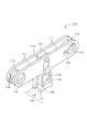
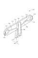
本発明の第1実施例であるチェーンガイド機構100、図1に示すように、エンジンルーム内のクランク軸に取付けた駆動スプロケットS1とカム軸に取付けた一対の従動スプロケットS2、S3間にタイミングチェーンCが無端懸回されるエンジンのタイミングシステムに用いられる。
Below, the chain guide mechanism which is one Example of this invention is demonstrated based on drawing.
A
ガイドブリッジ110のアーム部111のそれぞれの端部には、揺動チェーンガイド120、固定チェーンガイド130が一体に取り付けられ、ガイドブリッジ110の基部113の先端面が駆動スプロケットS1に近接するようエンジンルーム内に配置され、揺動チェーンガイド120、固定チェーンガイド130のそれぞれの円筒状の取付ボス部121、131に取付軸B1、B2が挿入されてチェーンガイド機構100がエンジンルーム内に固定される。
An
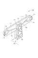
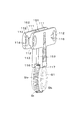
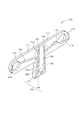
ガイドブリッジ110は、図2、図3に示すように、中央に設けられた基部113から両側に向かって、それぞれ1対のアーム部111が延びるように構成され、各アーム部111の先端側にはそれぞれガイド取付孔112が設けられている。
As shown in FIGS. 2 and 3, the
また、固定チェーンガイド130が取り付けられるガイド取付孔112には切り欠き115が設けられており、各アーム部111のガイド取付孔112のさらに先端側には、対になった各アーム部111の対向側に突出するガイド外れ防止突起114が設けられている。
Further, a
ガイドブリッジ110の基部113は、各アーム部111の中央から略T字状に延びており、その先端部は、スプロケット歯の通過を許容する溝部116と、該溝部116の両側でスプロケットのボス部と摺接可能な摺接部117からなるスプロケット押え部140を形成している。
また、基部113は、リブ119で補強された肉抜き部118を有していることで強度を下げることなく軽量化されている。
The
Further, the
ガイドブリッジ110の基部113のアーム部111側の先端にはV字状部151が形成され、基部113のチェーン通過側表面には、V字状部151からスプロケット押え部140の溝部116に至る基部誘導溝153が形成されている。
ガイドブリッジ110の各アーム部111の対向内面側には、ガイド取付孔112およびガイド取付孔112の切り欠き115の先端部から基部113側面に設けられた基部誘導溝153に繋がるアーム誘導溝152が設けられている。
A V-shaped
On the opposite inner surface side of each
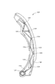
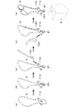
揺動チェーンガイド120は、図4に示すように、揺動軸となる円筒状の取付ボス部121が幅方向に突出するように設けられている。
揺動チェーンガイド120は、前述した1対のアーム部111に挟まれ、取付ボス部121がガイド取付孔112に係合することで、ガイドブリッジ110に揺動可能に保持される。
As shown in FIG. 4, the
The swinging
揺動チェーンガイド120の側面には、補強リブ123が設けられるとともに、補強リブ123には、図面矢印で示すように取付ボス部121に向けて向けての潤滑油の流動を促す切り欠き溝124が設けられている。
A reinforcing
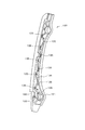
固定チェーンガイド130は、図5に示すように、円筒状の取付ボス部131が幅方向に突出するように設けられるとともに、取付ボス部131の外周に係合突起133が設けられている。
固定チェーンガイド130は、前述した1対のアーム部111に挟まれ、取付ボス部131がガイド取付孔112に係合し、係合突起133が切り欠き115と係合することで、ガイドブリッジ110に固定的に保持される。
As shown in FIG. 5, the
The
固定チェーンガイド130の側面には、補強リブ134が設けられるとともに、補強リブ134には、図面矢印で示すように係合突起133に向けて向けての潤滑油の流動を促す切り欠き溝135が設けられている。
Reinforcing
なお、ガイドブリッジ110の各アーム部111に設けられたガイド外れ防止突起114は、揺動チェーンガイド120、固定チェーンガイド130のチェーン走行案内面122、132の反対側に突出することで、揺動チェーンガイド120、固定チェーンガイド130の離脱を防止する。
The guide
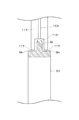
ガイドブリッジ110の基部113の先端のスプロケット押え部140は、図7に模式的に示すように、駆動スプロケットS1の歯Stの通過を許容する溝部116と、該溝部116の両側で駆動スプロケットS1のボス部Shと摺接可能な摺接部117からなり、組立やメンテナンス時に、摺接部117を駆動スプロケットS1のボス部Shに当接させてチェーンガイド機構100と駆動スプロケットS1とを一体として取り扱うことを可能とするとともに、エンジンへの組み付け後は、駆動スプロケットS1と基部113が干渉しないように構成されている。
As schematically shown in FIG. 7, the
次に、本発明の一実施例であるチェーンガイド機構100を、エンジンに組み付ける際の動作について説明する。
まず、図8(a)に示すように、ガイドブリッジ110の基部113の両側のそれぞれの1対のアーム部111の内側にタイミングチェーンCをセットし、図8(b)に示すように、基部113の先端のスプロケット押え部140に駆動スプロケットS1を当接させて、タイミングチェーンCでガイドブリッジ110と駆動スプロケットS1を固定する。
Next, the operation | movement at the time of assembling | attaching the
First, as shown in FIG. 8A, the timing chain C is set inside each of the pair of
次に、図8(c)、図8(d)に示すように、それぞれの1対のアーム部111の先端部の固定チェーンガイド130および揺動チェーンガイド120を挿入して、それぞれガイド取付孔112に取付ボス部131、121を嵌合させて、ガイドブリッジ110と固定チェーンガイド130および揺動チェーンガイド120を一体とする。
Next, as shown in FIGS. 8 (c) and 8 (d), the
この時、固定チェーンガイド130の取付ボス部131の外周に設けられた係合突起133は、ガイド取付孔112に設けられた切り欠き115と係合することで、固定チェーンガイド130がガイド取付孔112を中心として回転しないように固定される。
At this time, the
そして、図8(e)に示すように、ガイドブリッジ110、固定チェーンガイド130、揺動チェーンガイド120、タイミングチェーンCおよび駆動スプロケットS1が一体的にエンジンブロックEに対してハンドリングされることで、組立やメンテナンス時の作業性が向上する。
Then, as shown in FIG. 8E, the
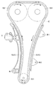
また、本発明の一実施例であるチェーンガイド機構100は、図9に示すように、ガイドブリッジ110の基部113の両側方にできる、基部113、固定チェーンガイド130あるいは揺動チェーンガイド120、1対のアーム部111で囲まれたそれぞれの空間内にタイミングチェーンCがセットされるため、タイミングチェーンCが蛇行したり振動したりしても、基部113および1対のアーム部111がチェーンガイドとして機能し、タイミングチェーンCの走行を安定させることができる。
In addition, as shown in FIG. 9, the
また、ガイドブリッジ110は駆動スプロケットS1の近くに設けられることで、小さなサイズとすることができ、製作が容易で寸法精度も高くすることができるとともに、チェーンとの摺接面を覆い隠すことがないため、タイミングシステム全体の潤滑や放熱の妨げとなることもない。
また、基部113の両側方の1対のアーム部111の長さも短く変形が少なくなり、ガイド取付孔112と取付ボス部121、131との離脱を防止することができる。
Further, the
Further, the length of the pair of
そして、エンジンブロックEの内部の潤滑油は、適宜の方法でエンジンブロックEの内部の適宜の場所に供給され、各構成部品の表面を流下するように構成されている。
固定チェーンガイド130あるいは揺動チェーンガイド120の側面を流下する潤滑油は、それぞれ切り欠き溝135、124を有する補強リブ134、123により、係合突起133および取付ボス部121に向けて集められつつ流下する。
The lubricating oil inside the engine block E is supplied to an appropriate place inside the engine block E by an appropriate method, and flows down the surface of each component.
The lubricating oil flowing down the side surface of the fixed
係合突起133および取付ボス部121に向けて集められた潤滑油は、ガイドブリッジ110の各アーム部111の対向内面側に設けられたアーム誘導溝152によって基部誘導溝153に誘導され、さらに該基部誘導溝153によってスプロケット押え部140の溝部116に誘導される。
このことで、スプロケットS1に充分に潤滑油を供給することができる。
The lubricating oil collected toward the engaging
Thus, the lubricating oil can be sufficiently supplied to the sprocket S1.
また、ガイドブリッジ110の基部113の上方から滴下する潤滑油は、先端に設けられたV字状部151で集められて、基部誘導溝153によってスプロケット押え部140の溝部116に誘導される。
このようにして潤滑油の誘導経路を備えることにより、スプロケットS1の上方にガイドブリッジ110が存在してもスプロケットS1に供給される潤滑油を充分に確保することができる。
Lubricating oil dripping from above the
By providing the lubricating oil guiding path in this way, it is possible to sufficiently secure the lubricating oil supplied to the sprocket S1 even if the
本発明の第2実施例であるチェーンガイド機構は、上記第1実施例とガイドブリッジ110の潤滑油の誘導経路が異なり、他の構成は同一である。
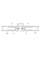
第2実施例のガイドブリッジ110は、図10に示すように、中央に設けられた基部113から両側に向かって、それぞれ1対のアーム部111が延びるように構成され、各アーム部111の先端側にはそれぞれガイド取付孔112が設けられている。
The chain guide mechanism according to the second embodiment of the present invention is different from the first embodiment in the guide route of the lubricating oil of the
As shown in FIG. 10, the
また、固定チェーンガイド130が取り付けられるガイド取付孔112には切り欠き115が設けられており、各アーム部111のガイド取付孔112のさらに先端側には、対になった各アーム部111の対向側に突出するガイド外れ防止突起114が設けられている。
Further, a
ガイドブリッジ110の基部113は、各アーム部111の中央から略T字状に延びており、その先端部は、スプロケット歯の通過を許容する溝部116と、該溝部116の両側でスプロケットのボス部と摺接可能な摺接部117からなるスプロケット押え部140を形成している。
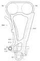
ガイドブリッジ110の基部113のアーム部111側の先端にはV字状部151が形成され、V字状部151からスプロケット押え部140の溝部116に至る基部貫通孔154が設けられている。
The
A V-shaped
基部113のチェーン通過側表面には、各アーム部111の対向内面からスプロケット押え部140の溝部116に至る基部誘導溝153が形成され、ガイドブリッジ110の各アーム部111の対向内面側には、ガイド取付孔112およびガイド取付孔112の切り欠き115の先端部から基部113側面に設けられた基部誘導溝153に繋がるアーム誘導溝152が設けられている。
このことにより、第1実施例の効果に加えて、ガイドブリッジ110の基部113の上方から滴下する潤滑油をさらに効率良くスプロケットS1に供給することができる。
A
Thus, in addition to the effects of the first embodiment, the lubricating oil dripping from above the
本発明の第3実施例であるチェーンガイド機構は、上記第1実施例とガイドブリッジ110の潤滑油の誘導経路が異なり、他の構成は同一である。
第3実施例のガイドブリッジ110は、図11に示すように、中央に設けられた基部113から両側に向かって、それぞれ1対のアーム部111が延びるように構成され、各アーム部111の先端側にはそれぞれガイド取付孔112が設けられている。
The chain guide mechanism according to the third embodiment of the present invention differs from the first embodiment in the guide route of the lubricating oil of the
As shown in FIG. 11, the
また、固定チェーンガイド130が取り付けられるガイド取付孔112には切り欠き115が設けられており、各アーム部111のガイド取付孔112のさらに先端側には、対になった各アーム部111の対向側に突出するガイド外れ防止突起114が設けられている。
Further, a
ガイドブリッジ110の基部113は、各アーム部111の中央から略T字状に延びており、その先端部は、スプロケット歯の通過を許容する溝部116と、該溝部116の両側でスプロケットのボス部と摺接可能な摺接部117からなるスプロケット押え部140を形成している。
ガイドブリッジ110の基部113のアーム部111側の先端にはV字状部151が形成され、V字状部151からスプロケット押え部140の溝部116に至る基部貫通孔154が設けられている。
The
A V-shaped
基部113のチェーン通過側表面には、基部113のチェーン通過側表面には、V字状部151からスプロケット押え部140の溝部116に至る基部誘導溝153が形成され、ガイドブリッジ110の各アーム部111の対向内面側には、ガイド取付孔112およびガイド取付孔112の切り欠き115の先端部から基部113側面に設けられた基部誘導溝153に繋がるアーム誘導溝152が設けられている。
A
また、基部誘導溝153と基部貫通孔154とを結ぶ側部貫通孔155が設けられている。
このことにより、第1実施例の効果に加えて、固定チェーンガイド130あるいは揺動チェーンガイド120から誘導された潤滑油とガイドブリッジ110の基部113の上方から滴下する潤滑油を、さらに効率良くかつスプロケットS1の表面に均等に供給することができる。
Further, a side through
As a result, in addition to the effects of the first embodiment, the lubricating oil guided from the fixed
なお、ガイド取付孔112と先端側に設けられるガイド外れ防止突起114との間隔を、固定チェーンガイド130側、および揺動チェーンガイド120側で異なるものとし、固定チェーンガイド130および揺動チェーンガイド120の取付ボス部131、121の周辺の形状を異なるものとしても良く、そのことで誤組み付けを防止することができる。
Note that the distance between the
また、上記実施例では、基部113の両側方の1対のアーム部111の延びる方向は、それぞれ基部113の駆動スプロケットS1側に伸びる方向と直角方向であるが、直角以外の角度で延びても良い。
また、それぞれのアーム部111はタイミングチェーンCの走行方向の側面のガイドとして、さらに幅広に形成されても良く、タイミングチェーンCの走行側面に対向する部分周辺のみを拡大したりタイミングチェーンCの走行方向に延ばした形状としても良い。
In the above embodiment, the extending direction of the pair of
Further, each
以上説明したように、本発明によれば、簡単な構成で複数のチェーンガイド、チェーンおよびスプロケットを一体保持可能とし、組立やメンテナンス時の作業性が向上し、スプロケットに充分に潤滑油を供給するなど、その効果は甚大である。 As described above, according to the present invention, a plurality of chain guides, chains, and sprockets can be integrally held with a simple configuration, workability during assembly and maintenance is improved, and sufficient lubricating oil is supplied to the sprockets. The effect is enormous.
さらに、ガイド取付孔112を既存の揺動チェーンガイド120や固定チェーンガイド130の取付ボス部121の形状に適合させることにより、既存の揺動チェーンガイド120や固定チェーンガイド130をそのまま使用可能であり、また、ガイド取付孔112を適合させるのが困難でも、既存の揺動チェーンガイド120や固定チェーンガイド130の取付ボス部121、131のみ設計変更することで使用可能となるため、製造コストの増加も抑制することができる。
Further, by adapting the
100 600 ・・・チェーンガイド機構
110、 610 ・・・ガイドブリッジ
111 ・・・アーム部
112、 612 ・・・ガイド取付孔
113 ・・・基部
114 ・・・ガイド外れ防止突起
115 ・・・切り欠き
116 ・・・溝部
117 ・・・摺接部
118 ・・・肉抜き部
119 ・・・リブ
120、520、620 ・・・揺動チェーンガイド
121、 621 ・・・取付ボス部
122 ・・・チェーン走行案内面
123 ・・・補強リブ
124 ・・・切り欠き溝
130、530、630 ・・・固定チェーンガイド
131 ・・・取付ボス部
132 ・・・チェーン走行案内面
133 ・・・係合突起
134 ・・・補強リブ
135 ・・・切り欠き溝
140 ・・・スプロケット押え部
151 ・・・V字状部
152 ・・・アーム誘導溝
153 ・・・基部誘導溝
154 ・・・基部貫通孔
C ・・・タイミングチェーン
S1 ・・・駆動スプロケット
St ・・・歯
Sh ・・・ボス部
S2、S3 ・・・従動スプロケット
T ・・・テンショナ
B、B1、B2 ・・・取付軸
E ・・・エンジンブロック
100 600 ...
Claims (7)
前記チェーンガイドが、円筒状の取付ボス部を備え、
前記ガイドブリッジが、前記複数のチェーンガイドを両端に保持するアーム部と、該アーム部の中間に設けられた基部とを有し、
前記ガイドブリッジのアーム部が、前記基部から両端に向かって前記チェーンガイドの両側面を挟むようにそれぞれ対になって延びるとともに、前記チェーンガイドの取付ボス部を嵌合保持するガイド取付孔を有し、
前記基部が、前記アーム部の中間部から略T字状に延び、その先端部にスプロケットに摺接するスプロケット押え部を有し、
該スプロケット押え部が、中央にスプロケット歯の通過を許容する溝部を有しているとともに、該溝部の両側にスプロケットのボス部と摺接可能な摺接部を有し、
前記ガイドブリッジが、前記アーム部の各ガイド取付孔から前記基部のスプロケット押え部の溝部に至る潤滑油通路を有していることを特徴とするチェーンガイド機構。 In a chain guide mechanism comprising a plurality of chain guides for sliding and guiding the chain and a guide bridge for holding the plurality of chain guides together,
The chain guide includes a cylindrical mounting boss,
The guide bridge has an arm part that holds the plurality of chain guides at both ends, and a base part provided in the middle of the arm part,
The arm portions of the guide bridge extend in pairs from the base portion toward both ends so as to sandwich both side surfaces of the chain guide, and have guide mounting holes for fitting and holding the mounting boss portions of the chain guide. And
The base portion has a sprocket pressing portion that extends in a substantially T shape from an intermediate portion of the arm portion, and that is in sliding contact with the sprocket at a tip portion thereof.
The sprocket pressing portion has a groove portion that allows passage of sprocket teeth at the center, and has sliding contact portions that can slide on the boss portion of the sprocket on both sides of the groove portion,
The chain guide mechanism, wherein the guide bridge has a lubricating oil passage from each guide mounting hole of the arm portion to a groove portion of the sprocket pressing portion of the base portion.
前記ガイドブリッジのガイド取付孔の少なくとも一つが、前記係合突起と係合する切り欠きを有し、
前記潤滑油通路が、該ガイド取付孔の切り欠きの先端部から延びていることを特徴とする請求項1または請求項2に記載のチェーンガイド機構。 One of the chain guides includes an engagement protrusion on the outer periphery of the cylindrical mounting boss part,
At least one of the guide mounting holes of the guide bridge has a notch that engages with the engaging protrusion,
3. The chain guide mechanism according to claim 1, wherein the lubricating oil passage extends from a front end portion of the notch of the guide mounting hole.
前記潤滑油通路が、該V字状の先端からスプロケット押え部の溝部に至る経路を有していることを特徴とする請求項1乃至請求項4のいずれかに記載のチェーンガイド機構。 The base of the guide bridge is formed in a V shape at the tip on the arm side,
The chain guide mechanism according to any one of claims 1 to 4, wherein the lubricating oil passage has a path extending from the V-shaped tip to a groove of the sprocket pressing portion.
Priority Applications (1)
| Application Number | Priority Date | Filing Date | Title |
|---|---|---|---|
| JP2010090663A JP5259643B2 (en) | 2010-04-09 | 2010-04-09 | Chain guide mechanism |
Applications Claiming Priority (1)
| Application Number | Priority Date | Filing Date | Title |
|---|---|---|---|
| JP2010090663A JP5259643B2 (en) | 2010-04-09 | 2010-04-09 | Chain guide mechanism |
Publications (2)
| Publication Number | Publication Date |
|---|---|
| JP2011220456A JP2011220456A (en) | 2011-11-04 |
| JP5259643B2 true JP5259643B2 (en) | 2013-08-07 |
Family
ID=45037690
Family Applications (1)
| Application Number | Title | Priority Date | Filing Date |
|---|---|---|---|
| JP2010090663A Expired - Fee Related JP5259643B2 (en) | 2010-04-09 | 2010-04-09 | Chain guide mechanism |
Country Status (1)
| Country | Link |
|---|---|
| JP (1) | JP5259643B2 (en) |
Families Citing this family (1)
| Publication number | Priority date | Publication date | Assignee | Title |
|---|---|---|---|---|
| CN103758931B (en) * | 2014-02-12 | 2015-10-21 | 太仓斯普宁精密机械有限公司 | A kind of can the Chain link for chain grate of oil storage and chain |
Family Cites Families (7)
| Publication number | Priority date | Publication date | Assignee | Title |
|---|---|---|---|---|
| JPS6138355U (en) * | 1984-08-14 | 1986-03-10 | スズキ株式会社 | chain guide |
| US4869708A (en) * | 1988-04-15 | 1989-09-26 | Borg-Warner Transmission And Engine Components Corporation | Sprocket retention/chain guide assembly |
| US5647811A (en) * | 1996-01-18 | 1997-07-15 | Borg-Warner Automotive, Inc. | Chain tensioner with integral arm |
| JP3932613B2 (en) * | 1997-08-28 | 2007-06-20 | アイシン精機株式会社 | Timing chain mechanism |
| US6322469B1 (en) * | 2000-04-21 | 2001-11-27 | Borgwarner Inc. | Dual arm chain tensioner for contacting multiple chain strands |
| JP4026507B2 (en) * | 2003-02-17 | 2007-12-26 | 日産自動車株式会社 | Timing chain tooth skip prevention device |
| US8387244B2 (en) * | 2006-08-11 | 2013-03-05 | Borgwarner Inc. | Assembly system and method for a tensioned chain drive system |
-
2010
- 2010-04-09 JP JP2010090663A patent/JP5259643B2/en not_active Expired - Fee Related
Also Published As
| Publication number | Publication date |
|---|---|
| JP2011220456A (en) | 2011-11-04 |
Similar Documents
| Publication | Publication Date | Title |
|---|---|---|
| JP5355480B2 (en) | Chain guide mechanism | |
| JP4970525B2 (en) | Chain guide mechanism | |
| JP5234670B2 (en) | Chain guide mechanism | |
| US7524254B2 (en) | Guide for transmission device | |
| JP5631825B2 (en) | Guide for transmission | |
| JP2014040877A (en) | Chain guide | |
| JP6906840B2 (en) | Chain guide mechanism | |
| CA2360521C (en) | Tensioner device | |
| CN101563552B (en) | Silent chain | |
| CN111946782B (en) | Tensioning rod | |
| CN114763751A (en) | Chain guide mechanism | |
| JP5100709B2 (en) | Chain guide mechanism | |
| JP5259643B2 (en) | Chain guide mechanism | |
| JP6353346B2 (en) | Swing lever and tensioner unit | |
| CN116292791A (en) | Frame of chain guide mechanism | |
| KR101971321B1 (en) | Chain guide | |
| JP5100710B2 (en) | Chain guide mechanism | |
| JP2010014044A (en) | Timing system | |
| JP7421098B2 (en) | chain guide | |
| JP5014198B2 (en) | Camshaft drive device for vehicle engine | |
| JP7212072B2 (en) | CHAIN GUIDE AND CHAIN TRANSMISSION USING THE SAME | |
| JP2012122522A (en) | Oscillation chain guide | |
| JP5681561B2 (en) | Chain tensioner device | |
| JP2012047262A (en) | Mounting structure |
Legal Events
| Date | Code | Title | Description |
|---|---|---|---|
| A621 | Written request for application examination |
Free format text: JAPANESE INTERMEDIATE CODE: A621 Effective date: 20120315 |
|
| A977 | Report on retrieval |
Free format text: JAPANESE INTERMEDIATE CODE: A971007 Effective date: 20130312 |
|
| TRDD | Decision of grant or rejection written | ||
| A01 | Written decision to grant a patent or to grant a registration (utility model) |
Free format text: JAPANESE INTERMEDIATE CODE: A01 Effective date: 20130423 |
|
| A61 | First payment of annual fees (during grant procedure) |
Free format text: JAPANESE INTERMEDIATE CODE: A61 Effective date: 20130424 |
|
| FPAY | Renewal fee payment (event date is renewal date of database) |
Free format text: PAYMENT UNTIL: 20160502 Year of fee payment: 3 |
|
| R150 | Certificate of patent or registration of utility model |
Ref document number: 5259643 Country of ref document: JP Free format text: JAPANESE INTERMEDIATE CODE: R150 Free format text: JAPANESE INTERMEDIATE CODE: R150 |
|
| LAPS | Cancellation because of no payment of annual fees |