JP5259641B2 - Multi-directional input device - Google Patents
Multi-directional input device Download PDFInfo
- Publication number
- JP5259641B2 JP5259641B2 JP2010084368A JP2010084368A JP5259641B2 JP 5259641 B2 JP5259641 B2 JP 5259641B2 JP 2010084368 A JP2010084368 A JP 2010084368A JP 2010084368 A JP2010084368 A JP 2010084368A JP 5259641 B2 JP5259641 B2 JP 5259641B2
- Authority
- JP
- Japan
- Prior art keywords
- slider
- knob
- input device
- rotary
- rotation
- Prior art date
- Legal status (The legal status is an assumption and is not a legal conclusion. Google has not performed a legal analysis and makes no representation as to the accuracy of the status listed.)
- Expired - Fee Related
Links
Images


Landscapes
- Switches With Compound Operations (AREA)
Description
本発明は、放射方向への平行移動操作又は傾動操作、軸回りの回転操作を可能にした、例えば自動車の多方向入力装置に関する。 The present invention relates to a multidirectional input device for an automobile, for example, which enables a parallel movement operation or tilting operation in a radial direction and a rotation operation around an axis.
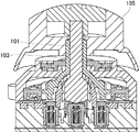
従来の多方向入力装置としては、図12に記載された複合操作型入力装置がある。 As a conventional multidirectional input device, there is a composite operation type input device shown in FIG.
この複合操作型入力装置は、軸状体である内軸101と外軸103とを有している。外軸103には、回転つまみ105が設けられている。
This composite operation type input device has an
回転つまみ105を回転させると、これに応じて外軸103が内軸101の回りで回転し、所定のスイッチ動作による出力を行わせることができる。
When the
回転つまみ105を放射方向へ傾倒操作すると、外軸103及び内軸101がともに傾斜動作し、所定のスイッチ動作による出力を行わせることができる。
When the
しかし、上記構造では、外軸103が内軸101の回りで回転する必要から両者間に最低限のクリアランスを必要とし、回転つまみ105を放射方向へ傾倒操作するとき、外軸103及び内軸101間のクリアランスにより操作のガタつきを感じるという問題があった。
However, in the above structure, since the
解決しようとする問題点は、放射方向へ操作するときに、操作のガタつきを感じる点である。 The problem to be solved is that it feels loose when operating in the radial direction.
本発明は、操作のガタつきを抑制することを可能とするため、ケースに対し回転規制を受けながら放射方向へ移動可能に設けられた移動スライダと、前記移動スライダの中央部の嵌合部に被嵌合部が嵌合し前記放射方向に交差する軸芯回りに相対回転可能に設けられた回転スライダと、前記回転スライダに係合して該回転スライダに放射方向へ力伝達が可能なノブと、前記嵌合部と前記被嵌合部との一方に形成された可撓部と同他方に形成され前記可撓部が弾接可能な受け部とを備え、前記移動スライダ及び回転スライダ間を、前記ケースに対し前記回転スライダの軸芯方向に拘束して前記可撓部を前記受け部に弾接させることを特徴とする。 According to the present invention, a moving slider provided to be movable in a radial direction while being restricted in rotation with respect to the case, and a fitting portion at a central portion of the moving slider are provided in order to suppress the play of the operation. A rotary slider that is fitted with a fitting portion and is rotatable relative to an axis that intersects the radial direction, and a knob that engages with the rotary slider and can transmit force to the rotary slider in the radial direction. A flexible portion formed on one of the fitting portion and the fitted portion, and a receiving portion formed on the other and capable of elastic contact with the flexible portion, and between the moving slider and the rotary slider Is restrained in the axial center direction of the rotary slider with respect to the case, and the flexible portion is elastically contacted with the receiving portion.
本発明の多方向入力装置は、ケースに対し回転規制を受けながら放射方向へ移動可能に設けられた移動スライダと、前記移動スライダの中央部の嵌合部に被嵌合部が嵌合し前記放射方向に交差する軸芯回りに相対回転可能に設けられた回転スライダと、前記回転スライダに係合して該回転スライダに放射方向へ力伝達が可能なノブと、前記嵌合部と前記被嵌合部との一方に形成された可撓部と同他方に形成され前記可撓部が弾接可能な受け部とを備え、前記移動スライダ及び回転スライダ間を、前記ケースに対し前記回転スライダの軸芯方向に拘束して前記可撓部を前記受け部に弾接させる。 The multi-directional input device according to the present invention includes a moving slider provided to be movable in a radial direction while being restricted in rotation with respect to the case, and a fitted portion fitted into a fitting portion at a central portion of the moving slider. A rotary slider provided so as to be relatively rotatable about an axis that intersects the radial direction, a knob that engages with the rotary slider and can transmit force to the rotary slider in the radial direction, the fitting portion, and the cover. A flexible portion formed on one side of the fitting portion and a receiving portion formed on the other side, the elastic portion being elastically contactable, and the rotary slider between the movable slider and the rotary slider with respect to the case The flexible portion is elastically brought into contact with the receiving portion in the axial direction.
このため、プリロードにより移動スライダ及び回転スライダ間のクリアランスを埋めることができ、放射方向へ動作させるときにガタつきを抑制し、操作感覚を向上させることができる。 For this reason, the clearance between the moving slider and the rotating slider can be filled by preloading, and rattling can be suppressed when operating in the radial direction, and the operational feeling can be improved.
操作のガタつきを抑制することを可能にするという目的を、移動スライダ及び回転スライダ間に放射方向へのプリロードを与えることにより実現した。 The object of making it possible to suppress the play of the operation is realized by giving a preload in the radial direction between the moving slider and the rotating slider.
[多方向スイッチの構造]
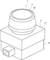
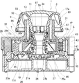
図1〜図3は、本発明の実施例1を示し、図1は、多方向スイッチの斜視図、図2は、多方向スイッチの平面図、図3は、図2のIII-III線矢視断面図である。なお、以下の説明において、ノブの回転軸方向をノブ回転軸方向、同回転半径方向をノブ回転半径方向、同回転周方向をノブ周方向とする。また、上下とは、車両の上下とする。
[Multi-directional switch structure]
1 to 3 show a first embodiment of the present invention, FIG. 1 is a perspective view of a multidirectional switch, FIG. 2 is a plan view of the multidirectional switch, and FIG. 3 is an arrow line III-III in FIG. FIG. In the following description, the rotation axis direction of the knob is the knob rotation axis direction, the rotation radius direction is the knob rotation radius direction, and the rotation circumferential direction is the knob circumferential direction. Moreover, the upper and lower sides are the upper and lower sides of the vehicle.
図1〜図3のように、本発明実施例の多方向入力装置である多方向スイッチ1は、ノブ3が、ケース5から突出し、ケース5内部に平行動作部7、回転スライダ9等を備えている。
As shown in FIGS. 1 to 3, in the
前記ノブ3は、ケース5に対し全体の平行移動操作及び押し込み操作、回転操作が可能に設けられている。ノブ3には、照明板3aが設けられ、内部には、結合中空軸部11が設けられている。この結合中空軸部11の中間部外周面には、回転係合部13が設けられている。
The knob 3 is provided to the
前記ケース5は、下ケース15及び上ケース17からなり、平面視で矩形に形成されている。下ケース15は、上ケース17にビス止めなどにより着脱可能に結合固定され、上ケース17は、車両のインストルメントやコンソールボックスに取り付けられ、ノブ3が上向き或いは斜め上向き等に配置されている。
The
前記下ケース15には、基板19が取り付けられ、この基板19上の中央部と周辺部とにラバー・コンタクト21a,21b・・・,23a,23b,・・・が設けられ、基板19中央に照明用のLED24等が設けられている。下ケース15の中央部には、ロータ・スライダ25が回転可能に支持されている。ロータ・スライダ25は、下部にクシ歯状部25aを備えている。
A
ロータ・スライダ25の内周に押し込み連動体27が軸方向移動可能に嵌合している。押し込み連動体27の一端は、前記結合筒部11の端部に当接し、同他端は前記ラバー・コンタクト21a,21b・・・に当接している。
A
下ケース15には、プッシュ・ロッド29が可動支持され、上端に球面29aが形成され、下端がラバー・コンタクト23aに当接している。ラバー・コンタクト23b等にも同様の構造で図示しないプッシュ・ロッドが当接している。
A
前記上ケース17には、上面中央部にカバー筒部17aが設けられ、上ケース17の内下面に後記一対の溝部17eが設けられている。この溝部17eは、ノブ回転軸を挟んでノブ回転半径方向で対称に形成されている。上ケース17の内下面外周側には、節度面17bが形成されている。節度面17bは、ノブ回転軸を挟んで対称に形成されている。
The
上ケース17には、さらに凸条部17cが形成され、上ケース17の内下面17dからの凸条部17cの突出高さは、後述するXスライダ31の厚みよりも僅かに大きくなる寸法公差が与えられている。
The
前記平行動作部7は、前記ケース5に対し回転規制を受けながら前記ノブ3を放射方向へ平行移動操作可能に支持するもので、Xスライダ31,移動スライダ33を備えている。
The parallel operation unit 7 supports the knob 3 so that the case 3 can be translated in the radial direction while being restricted in rotation with respect to the
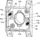
図4は、Xスライダ31及び移動スライダ33を配置した一部透視の上ケースの下面斜視図、図5は、Xスライダ31を配置した上ケースの下面斜視図である。
4 is a bottom perspective view of the partially transparent upper case in which the
図3〜図5のように、前記Xスライダ31には、一側面(図3上面)にノブ回転半径方向で配置された突状部31aが形成され、この突状部31aに直交してノブ回転半径方向に配置された溝部31bが他側面(図3下面)に形成されている。
As shown in FIGS. 3 to 5, the
前記Xスライダ31の突状部31aが上ケース17の溝部17eに嵌合してXスライダ31が上ケース17に対しX方向移動が可能であり、このXスライダ31の溝部31bに移動スライダ33の後述する突状部51が嵌合して移動スライダ33がXスライダ31に対しY方向移動が可能となっている。これらXY方向への移動の組み合わせにより移動スライダ33は、上ケース17に対し回転規制を受けながら放射方向である図2のA〜H方向へ移動可能にガイドされる。
The
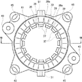
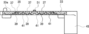
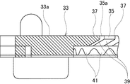
図6は、移動スライダの平面図、図7は、図6のVII-VII線矢視断面図である。 6 is a plan view of the moving slider, and FIG. 7 is a sectional view taken along the line VII-VII in FIG.
図3〜図7のように、移動スライダ33は、ほぼリング状に形成され、中央部に嵌合部35が円形孔として形成されている。この嵌合部35に、放射方向のスリット35aにより可撓部37が周方向一定間隔で連接されている。各可撓部37には、斜面39が形成されている。
As shown in FIGS. 3 to 7, the moving
移動スライダ33の下面には、可撓部37の外周側に節度山41が形成されている。移動スライダ33の外周部には、節度ばね支持部43とカム面45とが形成されている。節度ばね支持部43は、嵌合部35のノブ回転半径方向に一対対称に形成され、カム面45は、同90度配置で4か所に形成されている。
On the lower surface of the
各節度ばね支持部43には、図3のように節度ばね47及び節度ボール49が支持され、節度ボール49は、前記上ケース17の節度面17bに弾接している。これら節度面17b、節度ばね47及び節度ボール49は、移動スライダ33のノブ回転半径方向の放射方向への移動を元位置へ付勢する節度機構を構成する。
As shown in FIG. 3, a
各カム面45は、図3のように前記プッシュ・ロッド29の球面29aに当接している。
Each
図4、図6、図7のように、移動スライダ33の上面外周部には、嵌合部35のノブ回転半径方向で前記Xスライダ31の溝部31bに嵌合する前記突状部51が一対対称に形成されている。
As shown in FIGS. 4, 6, and 7, a pair of the protruding
図1〜図3のように、前記回転スライダ9は、上面中央部に結合筒部53が形成され、この結合筒部53上部内周面に被回転係合部55が形成されている。結合筒部53の外周は、被嵌合部57となっており、この被嵌合部57が移動スライダ33の嵌合部35に嵌合している。
As shown in FIGS. 1 to 3, the rotary slider 9 has a
したがって、回転スライダ9は、前記移動スライダ33の中央部の嵌合部35に被嵌合部57が嵌合し前記放射方向に交差するノブ回転軸方向の軸芯回りに相対回転可能に設けられた構成となっている。
Therefore, the rotary slider 9 is provided so as to be relatively rotatable about the axis in the knob rotation axis direction intersecting with the radial direction by fitting the fitted
これら回転スライダ9及び移動スライダ33は、上下ケース17,15の前記ビス止め等による結合で上下ケース17,15相互間に挟まれている。この挟み込みにより、移動スライダ33の上面33aは、上ケース17の凸条部17cに支持され、移動スライダ33の上面33aと上ケース17の内下面17dとの間に、Xスライダ31の厚みよりも若干大きな隙間が形成される。
The rotary slider 9 and the
この挟み込みにより、移動スライダ33及び回転スライダ9間の位置関係を、前記ケース5に対し前記回転スライダ9の軸芯方向に拘束して前記可撓部37を後述する受け部67に弾接させている。
By this sandwiching, the positional relationship between the
結合筒部53の下部側内周面には、ばね受け部59が形成され、ばね受け部59の内周に、ノブ下端嵌合支持部61が形成され下方へ延設されている。前記ノブ3は、上ケース17のカバー筒部17aを覆うように装着され、結合中空軸部11が結合筒部53に嵌合し、回転係合部13が被回転係合部55に回転係合している。
A
この回転係合は、ノブ3の回転スライダ9に対するノブ回転軸方向への押し込み動作を可能としつつ、ノブ3の回転操作を回転スライダ9の回転として伝達する。 The rotation engagement transmits the rotation operation of the knob 3 as the rotation of the rotary slider 9 while enabling the knob 3 to be pushed in the direction of the knob rotation axis with respect to the rotary slider 9.
ノブ3の結合中空軸部11下端は、ノブ下端嵌合支持部61に嵌合支持されている。結合中空軸部11のノブ下端嵌合支持部61への嵌合支持と前記回転係合部13及び被回転係合部55間の嵌合とによりノブ3からノブ回転半径方向への力伝達を行わせることができ、回転スライダ9が放射方向へ選択的に平行移動動作する。
The lower end of the coupling
ばね受け部59と結合中空軸部11とのノブ回転軸方向間には、リターン・スプリング63が介設され、ノブ下端嵌合支持部61の外周と前記ロータ・スライダ25の外周との間には、ロータ伝達スプリング65が介設されている。このロータ伝達スプリング65は、回転スライダ9の回転を捩じれトルクによりロータ・スライダ25に伝達するものである。
A
回転スライダ9及びロータ・スライダ25間の回転伝達をロータ伝達スプリング65にしたことで、ロータ・スライダ25に対し移動スライダ33に伴った回転スライダ9の平行移動を可能とする。
Since the rotation transmission between the rotary slider 9 and the
したがって、ノブ3は、回転スライダ9に回転係合して押し込み操作可能に設けられ該回転スライダ9に放射方向へ力伝達が可能な構成となっている。 Therefore, the knob 3 is provided so as to be able to be pushed in by being rotationally engaged with the rotary slider 9, and is configured to transmit force to the rotary slider 9 in the radial direction.
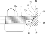
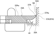
図9は、移動スライダ33及び回転スライダ9間の弾接を示す要部の拡大断面図である。
FIG. 9 is an enlarged cross-sectional view of the main part showing the elastic contact between the moving
図3、図9のように、被嵌合部57には、前記可撓部37が弾接可能な受け部67が周回状に形成されている。受け部67には、曲面67aが形成され、前記可撓部37の斜面39に弾接している。この弾接により可撓部37が適度に撓み、適切なプリロードとなる。
As shown in FIGS. 3 and 9, the
この可撓部37の撓みは、移動スライダ33の上面33aと上ケース17の内下面17dとの間の、Xスライダ31の厚みよりも若干大きな隙間の設定により吸収することができる。
The bending of the
前記回転スライダ9には、受け部67よりも外周側に節度ボール69(図4)及び節度スプリング71(図4)がノブ回転半径方向で対称に一対支持され、節度ボール69が、移動スライダ33の節度山41に弾接している。
A pair of moderation balls 69 (FIG. 4) and moderation springs 71 (FIG. 4) are supported on the rotary slider 9 on the outer peripheral side of the receiving
この節度山41に対する節度ボール69の弾接は、移動スライダ33に対する回転スライダ9の回転節度を持たせる節度機構となる。このため、移動スライダ33が節度山41の位置で撓まない状態とし、回転スライダ9側の節度ボール69を節度山41へ設計通りに弾接させる必要がある。そこで、スリット35aの外周位置を節度山41まで及ばない位置まで形成し前記可撓部37のみを適度に撓ませて受け部67に弾接させることで移動スライダ33が節度山41の位置で撓まないようにした。
The elastic contact of the moderation ball 69 against the
この結果、移動スライダ33及び回転スライダ9間の節度機構を設計通りとし、移動スライダ33に対する回転スライダ9の回転節度を正確に持たせることができる。
As a result, the moderation mechanism between the
[平行移動操作]
前記ノブ3を掌で握り、ノブ回転半径方向へ平行移動させ、図2のA〜Hの8方向の何れかへ操作することができる。
[Translation operation]
The knob 3 can be gripped with a palm, translated in the knob rotation radius direction, and operated in any of the eight directions A to H in FIG.
この操作により、ノブ3の結合中空軸部11から回転スライダ9の結合筒部53に操作力が伝達され、この操作力が被嵌合部57の受け部67から曲面67aを介して可撓部37の斜面39に伝達され、可撓部37がA〜Hの8方向の何れかの方向への力を受ける。
By this operation, an operating force is transmitted from the coupling
この力により移動スライダ33が前記XY方向への移動の組み合わせにより上ケース17に対し回転規制を受けながら放射方向である図2のA〜H方向へ前記操作に応じて選択的に移動することができる。
With this force, the moving
このとき、可撓部37が受け部67に弾接して移動スライダ33及び回転スライダ9間に放射方向へのプリロードが与えられているため、回転スライダ9の結合筒部53から移動スライダ33の嵌合部35へガタ付なく直ちに力を伝達することができる。
At this time, since the
移動スライダ33のA〜H方向への選択的な移動によりカム面45は、球面29aを介してプッシュ・ロッド29を押し下げ、対応するラバー・コンタクト23a,23b,・・・の接点動作を行わせることができる。
By the selective movement of the moving
移動スライダ33がA〜H方向の何れかへ移動したときは、移動方向で節度面17bにより節度ボール49が応圧され、節度ばね47が圧縮される。この節度ばね47の圧縮によりノブ3から手を離すと節度ばね47の弾発力により節度ボール49が節度面17bの傾斜に沿って元位置へ戻り、移動スライダ33が復帰する。この移動スライダ33が復帰によりノブ3も元の位置に自動的に戻る。
[回転操作]
前記ノブ3をノブ回転軸周りで回転操作すると、結合中空軸部11から回転スライダ9の結合筒部53に回転係合部13及び被回転係合部55を介して回転操作力が伝達される。この回転伝達により回転スライダ9が回転し、この回転がロータ伝達スプリング65を介してロータ・スライダ25に伝達される。
When the moving
[Rotation operation]
When the knob 3 is rotated around the rotation axis of the knob, the rotational operation force is transmitted from the coupling
ロータ・スライダ25の回転によりクシ歯状部25aがケース5側の不図示のフォト・センサに対して相対回転して回転が検出され、指示動作を行わせることができる。
[押し込み操作]
前記ノブ3をノブ回転軸方向へ押し込み操作すると、回転係合部13が被回転係合部55に対してノブ回転軸方向へスライドし、ノブ3を押し込み動作させることができる。
As a result of the rotation of the
[Push-in operation]
When the knob 3 is pushed in in the knob rotation axis direction, the
このノブ3の押し込み動作により結合中空軸部11を介して押し込み連動体27に押し込み力が伝達され、押し込み連動体27によりラバー・コンタクト21a,21b,・・・の接点動作を行わせることができる。
By the pushing operation of the knob 3, the pushing force is transmitted to the pushing interlocking
ノブ3の押し込み動作によりリターン・スプリング63がばね受け部59との間で圧縮される。このリターン・スプリング63の圧縮によりノブ3から手を離すとリターン・スプリング63の弾発力によりノブ3が元の位置に自動的に戻される。
[照明]
前記LED24を発光させると、光が押し込み連動体27及び結合中空軸部11を通り照明板3aまで直接届く。この光により照明板3aを明光表示させることができる。
[実施例1の効果]
本発明実施例1の多方向入力スイッチ1は、ケース5に対し回転規制を受けながら放射方向のA〜H方向へ選択的に移動可能に設けられた移動スライダ33と、前記移動スライダ33の中央部の嵌合部35に被嵌合部57が嵌合し前記放射方向に交差するノブ回転軸の軸芯回りに相対回転可能に設けられた回転スライダ9と、前記回転スライダ9に係合したノブ3と、前記嵌合部35に形成された可撓部37と前記被嵌合部57に形成され前記可撓部37が弾接可能な受け部67とを備え、前記移動スライダ33及び回転スライダ9間を、前記ケース5に対し前記回転スライダ9の軸芯方向に拘束して前記可撓部37を前記受け部67に弾接させた。
The
[illumination]
When the
[Effect of Example 1]
The
このため、プリロードにより移動スライダ及び回転スライダ間のクリアランスを埋めることができ、放射方向へ動作させるときにガタつきを抑制し、操作感覚を向上させることができる。 For this reason, the clearance between the moving slider and the rotating slider can be filled by preloading, and rattling can be suppressed when operating in the radial direction, and the operational feeling can be improved.
また、回転スライダ9から移動スライダ33へガタ付なく力を伝達することができ、ノブ3のA〜H方向の何れかへの操作により対応するラバー・コンタクト23a,23b,・・・の接点動作をガタ付なく行わせることができる。
Further, the force can be transmitted from the rotary slider 9 to the moving
可撓部37は、受け部67に弾接して適度に撓むため、適切なプリロードとなり、移動スライダ33に対する回転スライダ9の相対回転も無理なく行わせることができる。
Since the
前記プリロードを与えるためのばねは、可撓部37の弾性を利用しているため、特別なばね部材を必要とせず、部品点数の増加はなく、構造が簡単である。
Since the spring for applying the preload utilizes the elasticity of the
前記可撓部37と前記受け部67とに、前記放射方向に当接する斜面39と曲面67aとを各別に設けた。
The
このため、可撓部37と受け部67との間の弾接を全周で確実に行わせることができる。
For this reason, the elastic contact between the
前記可撓部37は、前記嵌合部35に設けられた放射方向のスリット35aにより形成された。
The
このため、移動スライダ33及び回転スライダ9間の節度機構を設計通りとし、移動スライダ33に対する回転スライダ9の回転節度を正確に持たせることができる。また、可撓部37を簡単に形成することができる。
For this reason, the moderation mechanism between the moving
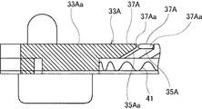
図10、図11は、本発明の実施例2に係り、図10は、移動スライダの要部の拡大断面図、図11は、移動スライダ及び回転スライダ間の弾接を示す要部の拡大断面図である。なお、基本的な構成は実施例1と同様であり、同一又は対応する構成部分には同符号又は同符号にAを付し、重複した説明は省略する。 10 and 11 relate to the second embodiment of the present invention, FIG. 10 is an enlarged cross-sectional view of the main part of the moving slider, and FIG. 11 is an enlarged cross-sectional view of the main part showing the elastic contact between the moving slider and the rotary slider. FIG. Note that the basic configuration is the same as that of the first embodiment, and the same or corresponding components are denoted by the same reference numerals or the same reference numerals, and redundant description is omitted.
図10、図11のように、本実施例の多方向スイッチは、嵌合部35Aの可撓部37A先端に曲面37Aaが形成されている。結合筒部53Aには、同径で被嵌合部57Aが形成されている。本実施例では、被嵌合部57Aがそのまま受け部67Aを構成している。
As shown in FIGS. 10 and 11, the multidirectional switch of this embodiment has a curved surface 37Aa at the tip of the
可撓部37A先端の曲面37Aaが被嵌合部57Aに嵌合して可撓部37Aが受け部67Aで受けられてノブ回転軸方向へ撓み、実施例1同様にプリロードをかけることができる。
The curved surface 37Aa at the tip of the
したがって、本実施例でも、実施例1と同様な作用効果を奏することができる。
[その他]
前記曲面67aを可撓部37に設け、前記斜面39を受け部67に設けることもできる。
Therefore, this embodiment can achieve the same effects as those of the first embodiment.
[Others]
The
前記可撓部37,37Aは、前記スリット35,35Aによらず、部分的な薄肉などにより形成することもできる。
The
本実施例のノブを、図12のように傾動操作する構造に適用することもできる。この場合、平行動作部7、この平行動作部7に対向する回転スライダ9の上面等は、球面状に形成されることになる。 The knob of this embodiment can also be applied to a structure that tilts as shown in FIG. In this case, the parallel operation unit 7 and the upper surface of the rotary slider 9 facing the parallel operation unit 7 are formed in a spherical shape.
1 多方向スイッチ(多方向入力装置)
3 ノブ
5 ケース
7 プッシュ・ロッド
9 回転スライダ
15 下ケース
17 上ケース
33 移動スライダ
35 嵌合部
37,37A 可撓部
47 節度ばね(ばね部)
57,57A 被嵌合部
67,67A 受け部
67a,37Aa 曲面
1 Multidirectional switch (Multidirectional input device)
3
57,
Claims (4)
前記移動スライダの中央部の嵌合部に被嵌合部が嵌合し前記放射方向に交差する軸芯回りに相対回転可能に設けられた回転スライダと、
前記回転スライダに係合し該回転スライダに放射方向へ力伝達が可能なノブと、
前記嵌合部と前記被嵌合部との一方に形成された可撓部と同他方に形成され前記可撓部が弾接可能な受け部とを備え、
前記移動スライダ及び回転スライダ間を、前記ケースに対し前記回転スライダの軸芯方向に拘束して前記可撓部を前記受け部に弾接させる、
ことを特徴とする多方向入力装置。 A movable slider provided so as to be movable in the radial direction while receiving rotation restriction with respect to the case;
A rotary slider provided so that a fitting portion is fitted to a fitting portion at a central portion of the moving slider and is relatively rotatable around an axis that intersects the radial direction;
A knob that engages with the rotary slider and is capable of transmitting force to the rotary slider in a radial direction;
A flexible portion formed on one of the fitting portion and the fitted portion, and a receiving portion formed on the other and capable of elastic contact with the flexible portion,
Between the movable slider and the rotary slider, the flexible portion is elastically contacted with the receiving portion by restraining the case in the axial direction of the rotary slider.
A multidirectional input device characterized by that.
前記ケースは、上下ケースからなり、
前記移動スライダ及び回転スライダを、前記上下ケース間に挟んだ、
ことを特徴とする多方向入力装置。 The multi-directional input device according to claim 1,
The case consists of upper and lower cases,
The movable slider and the rotary slider are sandwiched between the upper and lower cases,
A multidirectional input device characterized by that.
前記可撓部と前記受け部とに、前記放射方向に当接する斜面と曲面とを各別に設けた、
ことを特徴とする多方向入力装置。 The multi-directional input device according to claim 1 or 2,
The flexible portion and the receiving portion are each provided with a slope and a curved surface that are in contact with the radial direction,
A multidirectional input device characterized by that.
前記可撓部は、前記嵌合部又は被嵌合部に設けられた放射方向のスリットにより形成された、
ことを特徴とする多方向入力装置。 The multidirectional input device according to any one of claims 1 to 3,
The flexible part is formed by a radial slit provided in the fitting part or the fitted part,
A multidirectional input device characterized by that.
Priority Applications (1)
| Application Number | Priority Date | Filing Date | Title |
|---|---|---|---|
| JP2010084368A JP5259641B2 (en) | 2010-03-31 | 2010-03-31 | Multi-directional input device |
Applications Claiming Priority (1)
| Application Number | Priority Date | Filing Date | Title |
|---|---|---|---|
| JP2010084368A JP5259641B2 (en) | 2010-03-31 | 2010-03-31 | Multi-directional input device |
Publications (2)
| Publication Number | Publication Date |
|---|---|
| JP2011216368A JP2011216368A (en) | 2011-10-27 |
| JP5259641B2 true JP5259641B2 (en) | 2013-08-07 |
Family
ID=44945895
Family Applications (1)
| Application Number | Title | Priority Date | Filing Date |
|---|---|---|---|
| JP2010084368A Expired - Fee Related JP5259641B2 (en) | 2010-03-31 | 2010-03-31 | Multi-directional input device |
Country Status (1)
| Country | Link |
|---|---|
| JP (1) | JP5259641B2 (en) |
Families Citing this family (2)
| Publication number | Priority date | Publication date | Assignee | Title |
|---|---|---|---|---|
| KR101537023B1 (en) * | 2013-11-19 | 2015-07-15 | 양두영 | Jog shuttle |
| WO2016133228A1 (en) * | 2015-02-16 | 2016-08-25 | 양두영 | Jog shuttle |
Family Cites Families (4)
| Publication number | Priority date | Publication date | Assignee | Title |
|---|---|---|---|---|
| JPH0877882A (en) * | 1994-09-02 | 1996-03-22 | Aiwa Co Ltd | Slide operation device |
| JP4617217B2 (en) * | 2005-08-05 | 2011-01-19 | ナイルス株式会社 | Multi-directional input device |
| JP4349462B2 (en) * | 2008-02-27 | 2009-10-21 | オムロン株式会社 | INPUT DEVICE AND ELECTRONIC DEVICE HAVING THE INPUT DEVICE |
| JP2009272093A (en) * | 2008-05-02 | 2009-11-19 | Alps Electric Co Ltd | Multi-directional input apparatus |
-
2010
- 2010-03-31 JP JP2010084368A patent/JP5259641B2/en not_active Expired - Fee Related
Also Published As
| Publication number | Publication date |
|---|---|
| JP2011216368A (en) | 2011-10-27 |
Similar Documents
| Publication | Publication Date | Title |
|---|---|---|
| US9052736B2 (en) | Control system with displaceable knob | |
| JP2012221341A (en) | Joy stick device | |
| JP5797444B2 (en) | Joystick device | |
| JP6410358B2 (en) | Rotating switch device | |
| JP6228954B2 (en) | Lever device | |
| JP6660527B2 (en) | Input device | |
| CN110233077B (en) | Knob switch | |
| JP2009064638A (en) | Combined operation device | |
| JP5259641B2 (en) | Multi-directional input device | |
| JP5241682B2 (en) | Lever operation device | |
| JP7125557B2 (en) | Operating device | |
| US20060290675A1 (en) | Ball device for controlling cursor | |
| JP4590432B2 (en) | Operating device and operating system | |
| JP4637301B2 (en) | Multi-directional input device | |
| JP6934625B2 (en) | Combined operation input device | |
| JP6231437B2 (en) | Lever device | |
| JP4617216B2 (en) | Multi-directional input device | |
| JP2013242972A (en) | Multidirectional input device | |
| JP2019102404A (en) | Lever switch device | |
| JP5778627B2 (en) | Rotary switch device | |
| JP2015216038A (en) | Operation lever device | |
| EP3214632B1 (en) | Multidirectional input device | |
| JP2007173098A (en) | Multidirectional switch device | |
| JP4617217B2 (en) | Multi-directional input device | |
| JPH10254620A (en) | Three-dimensional data input device |
Legal Events
| Date | Code | Title | Description |
|---|---|---|---|
| A621 | Written request for application examination |
Free format text: JAPANESE INTERMEDIATE CODE: A621 Effective date: 20120320 |
|
| A977 | Report on retrieval |
Free format text: JAPANESE INTERMEDIATE CODE: A971007 Effective date: 20130404 |
|
| TRDD | Decision of grant or rejection written | ||
| A01 | Written decision to grant a patent or to grant a registration (utility model) |
Free format text: JAPANESE INTERMEDIATE CODE: A01 Effective date: 20130416 |
|
| A61 | First payment of annual fees (during grant procedure) |
Free format text: JAPANESE INTERMEDIATE CODE: A61 Effective date: 20130424 |
|
| FPAY | Renewal fee payment (event date is renewal date of database) |
Free format text: PAYMENT UNTIL: 20160502 Year of fee payment: 3 |
|
| R150 | Certificate of patent or registration of utility model |
Free format text: JAPANESE INTERMEDIATE CODE: R150 |
|
| S111 | Request for change of ownership or part of ownership |
Free format text: JAPANESE INTERMEDIATE CODE: R313111 |
|
| R350 | Written notification of registration of transfer |
Free format text: JAPANESE INTERMEDIATE CODE: R350 |
|
| R250 | Receipt of annual fees |
Free format text: JAPANESE INTERMEDIATE CODE: R250 |
|
| R250 | Receipt of annual fees |
Free format text: JAPANESE INTERMEDIATE CODE: R250 |
|
| LAPS | Cancellation because of no payment of annual fees |