JP5259598B2 - Micro electro mechanical sensor and method of operating micro electro mechanical sensor - Google Patents
Micro electro mechanical sensor and method of operating micro electro mechanical sensor Download PDFInfo
- Publication number
- JP5259598B2 JP5259598B2 JP2009527708A JP2009527708A JP5259598B2 JP 5259598 B2 JP5259598 B2 JP 5259598B2 JP 2009527708 A JP2009527708 A JP 2009527708A JP 2009527708 A JP2009527708 A JP 2009527708A JP 5259598 B2 JP5259598 B2 JP 5259598B2
- Authority
- JP
- Japan
- Prior art keywords
- signal
- electrode
- force
- spring constant
- electrodes
- Prior art date
- Legal status (The legal status is an assumption and is not a legal conclusion. Google has not performed a legal analysis and makes no representation as to the accuracy of the status listed.)
- Expired - Fee Related
Links
Images

Classifications
-
- G—PHYSICS
- G01—MEASURING; TESTING
- G01C—MEASURING DISTANCES, LEVELS OR BEARINGS; SURVEYING; NAVIGATION; GYROSCOPIC INSTRUMENTS; PHOTOGRAMMETRY OR VIDEOGRAMMETRY
- G01C19/00—Gyroscopes; Turn-sensitive devices using vibrating masses; Turn-sensitive devices without moving masses; Measuring angular rate using gyroscopic effects
- G01C19/56—Turn-sensitive devices using vibrating masses, e.g. vibratory angular rate sensors based on Coriolis forces
- G01C19/5776—Signal processing not specific to any of the devices covered by groups G01C19/5607 - G01C19/5719
-
- G—PHYSICS
- G01—MEASURING; TESTING
- G01C—MEASURING DISTANCES, LEVELS OR BEARINGS; SURVEYING; NAVIGATION; GYROSCOPIC INSTRUMENTS; PHOTOGRAMMETRY OR VIDEOGRAMMETRY
- G01C19/00—Gyroscopes; Turn-sensitive devices using vibrating masses; Turn-sensitive devices without moving masses; Measuring angular rate using gyroscopic effects
- G01C19/56—Turn-sensitive devices using vibrating masses, e.g. vibratory angular rate sensors based on Coriolis forces
-
- B—PERFORMING OPERATIONS; TRANSPORTING
- B81—MICROSTRUCTURAL TECHNOLOGY
- B81B—MICROSTRUCTURAL DEVICES OR SYSTEMS, e.g. MICROMECHANICAL DEVICES
- B81B7/00—Microstructural systems ; Auxiliary parts of microstructural devices or systems
- B81B7/02—Microstructural systems ; Auxiliary parts of microstructural devices or systems containing distinct electrical or optical devices of particular relevance for their function, e.g. microelectro-mechanical systems [MEMS]
-
- G—PHYSICS
- G01—MEASURING; TESTING
- G01C—MEASURING DISTANCES, LEVELS OR BEARINGS; SURVEYING; NAVIGATION; GYROSCOPIC INSTRUMENTS; PHOTOGRAMMETRY OR VIDEOGRAMMETRY
- G01C19/00—Gyroscopes; Turn-sensitive devices using vibrating masses; Turn-sensitive devices without moving masses; Measuring angular rate using gyroscopic effects
- G01C19/56—Turn-sensitive devices using vibrating masses, e.g. vibratory angular rate sensors based on Coriolis forces
- G01C19/5719—Turn-sensitive devices using vibrating masses, e.g. vibratory angular rate sensors based on Coriolis forces using planar vibrating masses driven in a translation vibration along an axis
- G01C19/5726—Signal processing
Landscapes
- Engineering & Computer Science (AREA)
- Physics & Mathematics (AREA)
- General Physics & Mathematics (AREA)
- Radar, Positioning & Navigation (AREA)
- Remote Sensing (AREA)
- Signal Processing (AREA)
- Computer Hardware Design (AREA)
- Microelectronics & Electronic Packaging (AREA)
- Gyroscopes (AREA)
- Micromachines (AREA)
- Measurement Of Length, Angles, Or The Like Using Electric Or Magnetic Means (AREA)
- Investigating Or Analyzing Materials By The Use Of Fluid Adsorption Or Reactions (AREA)
- Pressure Sensors (AREA)
Abstract
Description
本発明は、微小電気機械センサ及び上記センサの操作方法に関するものである。 The present invention relates to a microelectromechanical sensor and a method for operating the sensor.
微小電気機械センサは、多くの技術製品の基礎となる。微小電気機械センサは、例えば航行の分野において価値があり、コリオリの角速度計として用いられている。微小電気機械センサの機能性は、コリオリの角速度計についての例を介して以下に示されるだろう。 Microelectromechanical sensors are the basis of many technical products. The microelectromechanical sensor is valuable in the field of navigation, for example, and is used as a Coriolis angular velocity meter. The functionality of the microelectromechanical sensor will be demonstrated below through an example for a Coriolis angular velocity meter.
コリオリの角速度計は、振動をもたらされる質点系を有している。上記質点系は一般的に、最初に互いに独立している複数の振動モードを有している。コリオリの角速度計の操作状態において、即ち微小電気機械センサの操作状態において、質点系特有の振動モードは人工的に励起される。この振動モードを以下では“励起振動”と称する。 Coriolis angular velocimeters have a mass system that causes vibrations. The mass system generally has a plurality of vibration modes that are initially independent of each other. In the operating state of the Coriolis angular velocity meter, that is, in the operating state of the microelectromechanical sensor, the vibration mode peculiar to the mass system is artificially excited. This vibration mode is hereinafter referred to as “excitation vibration”.
コリオリの角速度計が回転すると、質点系の上記励起振動からエネルギを取り出してそれを上記質点系のさらに別の振動モードに伝達するコリオリ力が発生する。上記さらに別の振動モードを以下では“読み取り振動”と称する。 When the Coriolis angular velocity meter rotates, a Coriolis force is generated that extracts energy from the excitation vibration of the mass system and transmits it to another vibration mode of the mass system. The further vibration mode is hereinafter referred to as “read vibration”.
コリオリの角速度計の回転運動を決定するために、上記読み取り振動は受け取られ(tapped off)、対応する読み取り信号は、コリオリの角速度計の回転に関する測定値を表す、生じた読み取り振動の振幅で変化するか否かを確かめるために審査される。コリオリの角速度計は、開ループ系及び閉ループ系の両方として実行されてもよい。閉ループ系では、上記読み取り振動の振幅は、対応する制御ループにより絶えず固定された値−好ましくは0に再設定され、復帰力が測定される。 To determine the rotational motion of the Coriolis angular velocity meter, the reading vibration is tapped off, and the corresponding reading signal varies with the amplitude of the resulting reading vibration, which represents a measurement related to the rotation of the Coriolis angular velocity meter. It will be reviewed to see if it will. The Coriolis angular velocity meter may be implemented as both an open loop system and a closed loop system. In a closed loop system, the amplitude of the reading vibration is reset to a value that is constantly fixed by the corresponding control loop—preferably zero, and the return force is measured.
コリオリの角速度計の(より一般には微小電気機械センサの)質点系(これ以降はさらに“共振器”と称する)は、この事例においては様々な方法で構成されてもよい。例えば、1つの構成要素で具現化された質点系を用いることが出来る。代りとして、ばね系を介して互いに連結された2つの振動器に上記質点系を分けることも出来、互いに相対的な動きを行ってもよい。 The mass system of Coriolis angular velocimeters (more commonly microelectromechanical sensors) (hereinafter further referred to as “resonators”) may be configured in various ways in this case. For example, a mass system embodied by one component can be used. Alternatively, the mass point system can be divided into two vibrators connected to each other via a spring system, and may move relative to each other.
周知の実施形態にかかるコリオリの角速度計20は、図1において概略を示される。コリオリの角速度計20は、電荷増幅器1、アナログ−デジタル変換器2、信号分離箇所3、復調器4,5、制御系6、変調器7、ドライバ8,9、共振器10及び電極系11を備えている。電極系11は、4つの電極111〜114を有している。
A Coriolis
共振器10は、電極111〜114による振動効果で励起されることが可能である。その上、共振器10のばね定数は、共振器10に設けられる電極(“移動可能な中央電極”)における電荷転送量Δqを測定することにより決定される。電荷の転送は、電極111〜114により生成される電界の中での共振器10の動きにより引き起こされる。上記電荷転送量に比例する信号S7は、電荷増幅器1によりアナログ−デジタル変換器2へ出力され、アナログ−デジタル変換器2により対応する信号S8に変換される。信号S8は、信号分離箇所3へ供給される。この信号から、復調器4,5、制御系6、変調器7及びドライバ8,9が動作することにより信号S3〜S6が生成される。信号S3〜S6は、電極111〜114へ供給され、補償されるコリオリ力により引き起こされる共振器10のゆがみを確実なものとする。コリオリの角速度計20の詳細な機能性に関しては、例えば特許明細書DE 103 20 675が参照される。
基礎となる本発明の目的は、例えば静電センサまたは圧電センサである微小電気機械センサの具体例を挙げることである。上記微小電気機械センサは、センサ電極が少数であるにもかかわらず広い機能性を有することが可能である。 The underlying object of the present invention is to give a specific example of a microelectromechanical sensor, for example an electrostatic sensor or a piezoelectric sensor. The microelectromechanical sensor can have wide functionality despite a small number of sensor electrodes.
上記目的を達成するために、本発明は請求項1に係る微小電気機械センサを提供する。その上本発明は、請求項11に係る微小電気機械センサの操作方法を提供する。本発明の好ましい構成及び開発概念は、独立請求項において示される。
In order to achieve the above object, the present invention provides a microelectromechanical sensor according to
本発明の微小電気機械センサは、
−少なくとも1つの移動可能な電極と、
−個別に駆動可能であり、対応する電極信号が供給されるための複数の電極を備え、移動可能な電極と離間して配置されている電極構成とを備え、
上記電極信号は、力の適用、ばね定数及び上記移動可能な電極の読み取り係数の、設定または変更のために静電気的に用いることが可能であり、
−上記電極構成に接続され、上記力の適用に関する信号、上記ばね定数に関する信号、及び上記移動可能な電極の上記読み取り係数に関する信号を供給され、上記力の適用、上記ばね定数、及び上記移動可能な電極の上記読み取り係数に関してもたらされる設定及び/または変更を定義する電極信号生成ユニットをさらに備え、
上記電極信号生成ユニットは、いわば上記力の適用に関する信号、上記ばね定数に関する信号、及び上記移動可能な電極の上記読み取り係数に関する信号に依存して各々の電極信号を生成し、上記力の適用、上記ばね定数、及び上記移動可能な電極の上記読み取り係数が、互いに独立して特定の所望値に設定及び/または変更されるように、複数の上記電極信号を互いに整合させる。
The microelectromechanical sensor of the present invention is
-At least one movable electrode;
A plurality of electrodes that can be individually driven and are provided with corresponding electrode signals, comprising an electrode configuration spaced apart from the movable electrodes;
The electrode signal can be used electrostatically for setting or changing force application, spring constant and read factor of the movable electrode,
-Connected to the electrode configuration and supplied with a signal relating to the application of the force, a signal relating to the spring constant, and a signal relating to the reading factor of the movable electrode, the application of the force, the spring constant and the movable An electrode signal generation unit that defines settings and / or changes to be effected with respect to the read coefficient of the electrode
The electrode signal generation unit generates each electrode signal depending on a signal related to the application of the force, a signal related to the spring constant, and a signal related to the read coefficient of the movable electrode, and the application of the force, The plurality of electrode signals are aligned with each other such that the spring constant and the read coefficient of the movable electrode are set and / or changed to a specific desired value independently of each other.
本発明の基礎となる本質的な見識は、上記力の適用、上記ばね定数、及び上記移動可能な電極の上記読み取り係数が、互いに独立して特定の所望値に設定及び/または変更されるように、任意の所望の電極構成に関する上記電極信号が互いに整合され、これにより上記微小電気機械センサに最大限の融通性を与えるということである。これに関連して、“任意の所望の電極構成”は、少なくとも3つの電極に関する、任意の所望の空間的な構成を意味する。 The essential insight underlying the present invention is that the application of the force, the spring constant, and the reading factor of the movable electrode are set and / or changed independently of one another to a specific desired value. In addition, the electrode signals for any desired electrode configuration are aligned with each other, thereby providing maximum flexibility to the microelectromechanical sensor. In this context, “any desired electrode configuration” means any desired spatial configuration for at least three electrodes.
既に上述したように、上記微小電気機械センサの上記質点系(これ以降はさらに“共振器”と称する)は、様々な方法で構成されてもよい。例えば、1つの構成要素で具現化された質点系を用いることが出来る。代りとして、ばね系を介して互いに連結された2つの振動器に上記質点系を分けることも出来、互いに相対的な動きを行ってもよい。 As already mentioned above, the mass system (hereinafter further referred to as “resonator”) of the microelectromechanical sensor may be constructed in various ways. For example, a mass system embodied by one component can be used. Alternatively, the mass point system can be divided into two vibrators connected to each other via a spring system, and may move relative to each other.
一実施形態において、本発明の微小電気機械センサは、上記移動可能な電極において生じる電荷の転送を検出する電荷転送ユニットが設けられており、上記移動可能な電極の瞬時の動きは、検出された上記電荷の転送に基づき評価ユニットにより決定される。 In one embodiment, the microelectromechanical sensor of the present invention is provided with a charge transfer unit that detects the transfer of charge generated in the movable electrode, and the instantaneous movement of the movable electrode is detected. It is determined by the evaluation unit based on the charge transfer.
一実施形態において、上記電極信号生成ユニットは、上記移動可能な電極において検出された上記電荷の転送が、上記移動可能な電極の動きと上記読み取り係数の値とから生じるただ1つの電荷転送成分を含むような方法で、いわば上記力の適用に関する信号、上記ばね定数に関する信号、及び上記移動可能な電極の上記読み取り係数に関する信号に依存して各々の電極信号を生成する。この事例において、上記読み取り係数は、上記移動可能な電極の動きの読み取りに関するゲイン係数として解釈されるべきである。 In one embodiment, the electrode signal generation unit is configured to transfer only one charge transfer component, wherein the transfer of the charge detected at the movable electrode results from the movement of the movable electrode and the value of the read coefficient. Each electrode signal is generated in such a way as to depend on a signal relating to the application of the force, a signal relating to the spring constant, and a signal relating to the read factor of the movable electrode. In this case, the reading factor should be interpreted as a gain factor for reading the movement of the movable electrode.
上記電極構成は、偶数の電極または奇数の電極を含んでもよい。その上、個々の電極の寸法及び構成は、互いに異なってもよい。1つの好ましい実施形態において、上記電極構成は、例えば2つの電極対に分類される4つの(好ましくは同一の)電極を含んでいる。
複数の上記電極は、第1の軸に関して軸方向に対称に構成される。上記第1の軸は、第2の軸に関して軸方向に対称に、かつ互いに2つの上記電極対を分離する。上記第2の軸は、各々の電極対の、複数の上記電極を互いに分離する。有利な方法では、上記移動可能な電極は、対称である2つの軸の交点に関して中心対称に構成される。
The electrode configuration may include an even number of electrodes or an odd number of electrodes. In addition, the dimensions and configuration of the individual electrodes may be different from one another. In one preferred embodiment, the electrode configuration comprises four (preferably identical) electrodes, for example classified into two electrode pairs.
The plurality of electrodes are configured symmetrically in the axial direction with respect to the first axis. The first axis is axially symmetrical with respect to the second axis and separates the two electrode pairs from each other. The second axis separates the plurality of electrodes of each electrode pair from each other. In an advantageous manner, the movable electrode is configured to be centrally symmetric with respect to the intersection of two axes that are symmetrical.
上記移動可能な電極が共振器の一部として表現される実施形態において、上記移動可能な電極は、振動効果で励起されることが可能であり、上記微小電気機械センサは、例えばコリオリの角速度計として用いることが可能である。 In an embodiment where the movable electrode is represented as part of a resonator, the movable electrode can be excited by a vibration effect, and the microelectromechanical sensor can be, for example, a Coriolis angular velocity meter Can be used.
2つの移動可能な電極、2つの電極構成及び2つの電極信号生成ユニットを含む実施形態において、両方の移動可能な電極は、2つの読み取り係数の内、対応する選ばれたものにより、互いに個別に読み取られ、(力の適用による影響を受ける)動き及びばね定数を、互いに個別に設定することが出来る。 In an embodiment comprising two movable electrodes, two electrode configurations and two electrode signal generation units, both movable electrodes are individually separated from each other by a corresponding selected one of the two read coefficients. The movements (influenced by the application of force) and the spring constants that are read can be set independently of each other.
本発明はさらに、移動可能な電極と、移動可能な電極と離間して配置され、個別に駆動可能であり、対応する電極信号が供給されるための複数の電極を備えている電極構成とを備える微小電気機械センサの操作方法を提供する。本発明の微小電気機械センサの操作方法は、
−いわば、力の適用に関する信号、ばね定数に関する信号及び読み取り係数に関する信号に依存し、上記力の適用、上記ばね定数及び上記移動可能な電極の上記読み取り係数に関して行われる設定及び/または変更を定義する電極信号を生成する工程と、
−上記力の適用、上記ばね定数、及び上記移動可能な電極の上記読み取り係数を静電気的に設定及び/または変更するために、対応する上記電極に上記電極信号を適用する工程とを含み、
複数の上記電極信号が、いわば上記力の適用に関する信号、上記ばね定数に関する信号、及び上記移動可能な電極の上記読み取り係数に関する信号に依存して生成され、上記力の適用、上記ばね定数、及び上記移動可能な電極の上記読み取り係数が、互いに独立して特定の所望値に設定及び/または変更されるように、複数の上記電極信号を互いに整合させる。
The present invention further comprises a movable electrode and an electrode configuration that is spaced apart from the movable electrode, is individually drivable, and comprises a plurality of electrodes for supplying corresponding electrode signals. A method for operating a microelectromechanical sensor is provided. The method of operating the microelectromechanical sensor of the present invention includes:
-So-called definition of settings and / or changes made with respect to the application of the force, the spring constant and the reading factor of the movable electrode, depending on the signal relating to the application of force, the signal relating to the spring constant and the signal relating to the reading factor. Generating an electrode signal to perform,
Applying the electrode signal to the corresponding electrode to electrostatically set and / or change the application of the force, the spring constant, and the read coefficient of the movable electrode;
A plurality of the electrode signals are generated depending on the signal relating to the application of the force, the signal relating to the spring constant, and the signal relating to the reading factor of the movable electrode, so that the application of the force, the spring constant, and A plurality of the electrode signals are aligned with each other such that the read coefficients of the movable electrodes are set and / or changed to specific desired values independently of each other.
本発明は、図面を参照した以下の典型的な実施形態においてよりに詳細に示される。 The invention is shown in more detail in the following exemplary embodiments with reference to the drawings.
図1は、周知の微小電気機械センサ(コリオリの角速度計)の基礎外略図である。 FIG. 1 is a basic schematic view of a known microelectromechanical sensor (Coriolis angular velocity meter).
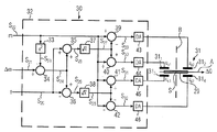
図2は、本発明に係る、1つの移動可能な電極を備える微小電気機械センサの実施形態を示す図である。 FIG. 2 is a diagram illustrating an embodiment of a microelectromechanical sensor comprising one movable electrode according to the present invention.
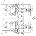
図3aは、本発明に係る、2つの移動可能な電極を備える微小電気機械センサの他の実施形態を示す図である。 FIG. 3a shows another embodiment of a microelectromechanical sensor comprising two movable electrodes according to the present invention.
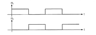
図3bは、2つの読み取り係数の適用に関する時間特性の概略を示すタイミングチャートである。 FIG. 3b is a timing chart showing an outline of the time characteristics for the application of two read coefficients.
図2は、本発明に係る微小電気機械センサ30の好ましい実施形態からの抜粋である。図2に示される抜粋は、変調器7、ドライバ8,9、共振器10及び電極111〜114を備える図1のコリオリの角速度計20の“全体像(ensemble)”と概要を比較される。
FIG. 2 is an excerpt from a preferred embodiment of a
図2は、移動可能な電極29と離間して配置された電極構成31を示す。移動可能な電極29は、例えば図示しない共振器の一部であってもよく、上記電極構成は、第1〜第4の電極311〜314を含んでいる。第1及び第3の電極311,313、並びに第2及び第4の電極312,314は、それぞれが電極対を形成している。電極対の複数の電極は、軸Aに関して軸方向に対称に構成される。複数の上記電極対は、軸Aと垂直である軸Bにより、互いに関して軸方向に対称かつ互いに分離される。移動可能な電極29は、例えば図2における対称な2つの軸A,Bの交点Sに関して中心対称に配置されている。
FIG. 2 shows an
電極信号生成ユニット32がさらに示されてもよい。電極信号生成ユニット32は、(さらに“f”として示される)力の適用に関する信号S20、(さらに“Δω”として示される)ばね定数に関する信号S21、及び(さらに“m”として示される)読み取り係数に関する信号S22を供給される。読み取り係数に関する信号S22は、2乗ユニット33により2乗され、これにより得られた信号S23が、第1の加算器34に負の符号を付されて供給される。上記信号S23は、ばね定数に関する信号S21と加算される。第1の加算器34の出力信号S24は、第2及び第3の加算器35,36に供給される。第2の加算器35において、出力信号S24は力の適用に関する信号S20と加算されるが、第3の加算器36において、負の符号を付された力の適用に関する信号S20は、出力信号S24と加算される。第2及び第3の加算器35,36の出力信号S25,S26は、根ユニット37,38に供給される。根ユニット37,38はそれぞれ、第2及び第3の加算器35,36の出力信号S25,S26の内の1つから根を算出する。根ユニット37,38の出力信号S27,S28は、第4〜第7の加算器39〜42に供給される。第4〜第7の加算器39〜42により、根ユニット37,38の出力信号S27,S28は、それぞれ読み取り係数に関する信号S22と一度加算されると共にそれぞれ読み取り係数に関する信号S22と一度減算される。対応する出力信号S29〜S32は、デジタル−アナログ変換器43〜46に供給される。デジタル−アナログ変換器43〜46は、(これまではデジタルであった)信号をアナログ信号uo1,uo2,uu1,uu2に変換し、アナログ信号uo1,uo2,uu1,uu2を対応する電極311〜314に供給する。アナログ信号uo1,uo2,uu1,uu2は、本発明の意図する電極信号を表し、力の適用に関する信号S20(=f)、ばね定数に関する信号S21(=Δω)、及び読み取り係数に関する信号S22(=m)により以下に示す(1)式〜(4)式で表される。
An electrode

それ故に、電極信号uo1,uo2は、軸Aの上方に位置する電極311,312で示される電極信号を表し、電極信号uu1,uu2は、軸Aの下方に位置する電極313,314で示される電極信号を表す。移動可能な電極29は仮想接地に接続され、移動可能な電極29からの電荷の転送が測定される。
Therefore, the electrode signals u o1 and u o2 represent the electrode signals indicated by the
図3は、移動可能であり、電気的に接続された2つの電極29,50が、どのようにして多様な方法で結合されるかを示している。図3bにおいて示されるタイミングにおいて切り替えられる制御信号m1,m2は、複数の移動可能な電極29,50が電荷増幅器70に交互に接続されるようにする。そのために、力の影響f1,f2及び整合Δω1,Δω2は独立して選択される。
FIG. 3 shows how two
図3は、第2の移動可能な電極50に対して離間して配置された電極構成51を示す。第2の移動可能な電極50は、少なくとも1つの移動可能な電極29と電気的に接続されている。上記電極構成は、第1〜第4の電極511〜514を含んでいる。第1及び第3の電極511,513、並びに第2及び第4の電極512,514は、それぞれが電極対を形成している。電極対の複数の電極は、軸A2に関して軸方向に対称に構成される。複数の上記電極対は、軸A2と垂直である軸B 2により、互いに関して軸方向に対称かつ互いに分離される。
FIG. 3 shows an
第2の電極信号生成ユニット32がさらに示されてもよい。電極信号生成ユニット32は、(さらに“f2”として示される)第2の力の適用に関する信号バーS20、(さらに“Δω2”として示される)第2のばね定数に関する信号バーS21、及び(さらに“m2”として示される)第2の読み取り係数に関する信号バーS22を供給される。第2の読み取り係数に関する信号バーS22は、2乗ユニット53により2乗され、これにより得られた信号バーS23が、第8の加算器54に負の符号を付されて供給される。上記信号バーS23は、第2のばね定数に関する信号バーS21と加算される。第8の加算器54の出力信号バーS24は、第9及び第10の加算器55,56に供給される。第9の加算器55において、出力信号バーS24は第2の力の適用に関する信号バーS20と加算されるが、第10の加算器56において、負の符号を付された力の適用に関する信号バーS20は、出力信号バーS24と加算される。第9及び第10の加算器55,56の出力信号バーS25,バーS26は、
根ユニット57,58に供給される。根ユニット57,58はそれぞれ、第9及び第10の加算器55,56の出力信号バーS25,バーS26の内の1つから根を算出する。根ユニット37,38の出力信号バーS27,バーS28は、第11〜第14の加算器59〜62に供給される。第11〜第14の加算器59〜62により、根ユニット57,58の出力信号バーS27,バーS28は、それぞれ読み取り係数に関する信号バーS22と一度加算されると共にそれぞれ読み取り係数に関する信号バーS22と一度減算される。対応する出力信号バーS29〜バーS32は、デジタル−アナログ変換器63〜66に供給される。デジタル−アナログ変換器63〜46は、(これまではデジタルであった)信号をアナログ信号バーuo1,バーuo2,バーuu1,バーuu2に変換し、アナログ信号バーuo1,バーuo2,バーuu1,バーuu2を対応する電極511〜514に供給する。アナログ信号バーuo1,バーuo2,バーuu1,バーuu2は、本発明の意図する電極信号を表し、力の適用に関する信号バーS20、ばね定数に関する信号バーS21、及び読み取り係数に関する信号バーS22により以下に示す(5)式〜(8)式で表される。
A second electrode
Supplied to the
![]()
![]()
それ故に、電極信号バーuo1,バーuo2は、軸A2の上方に位置する電極511,512で示される電極信号を表し、電極信号バーuu1,バーuu2は、軸A2の下方に位置する電極513,514で示される電極信号を表す。
Therefore, the electrode signal bar u o1, bar u o2 represent an electrode signal indicated by
本発明のさらに別の実施形態は、以下の記載により示される。 Yet another embodiment of the present invention is illustrated by the following description.
回転の加速度または回転速度の測定に関して、(これらを測定可能である)微小電気機械センサの動作中に、以下の要求が満足される場合は、上記測定に有利である。
1.定義され、電気的に生成された力を、移動可能な電極に及ぼすことが出来るように意図されている(トルカ(torquer)機能)。
2.定義され、電気的に生成されたばね力を、上記同一の移動可能な電極に及ぼすことが出来るように意図されている。ばね定数は一般に負であり、機械的な振動器の固有振動を定義されたように同調させることを可能にするために、正のばね特性を有する(positive)機械的なばねをある程度まで“よりソフトに(softer)”するように意図されている。
3.上記移動可能な電極のゆがみは、設定される読み取り係数により測定可能となるように意図されている(もぎ取り(pick-off)機能)。
4.1つの意図は、測定中に測定信号が、上記ゆがみ及び上記読み取り係数に依存する成分以外のさらに別のいかなる成分も含まないことを可能とすることである。
Regarding the measurement of rotational acceleration or rotational speed, it is advantageous for the measurement if the following requirements are satisfied during the operation of the microelectromechanical sensor (which can measure them).
1. It is defined and intended to be able to exert an electrically generated force on the movable electrode (torquer function).
2. It is defined and intended to be able to exert an electrically generated spring force on the same movable electrode. The spring constant is generally negative, and positive mechanical springs to some extent are “more” to allow the natural vibration of the mechanical vibrator to be tuned as defined. It is intended to be “softer”.
3. The distortion of the movable electrode is intended to be measurable with a set reading factor (pick-off function).
4. One intent is to allow the measurement signal not to contain any further components during measurement, other than components that depend on the distortion and the reading factor.
移動可能な電極を有している容量が設けられると考える。上記移動可能な電極は、作動点におけるゆがみxにより移動できる。このとき上記容量はゆがみxに依存し、C=C(x)となる。上記作動点において上記容量に電圧Uが供給される事例において、以下に示す(9)式で表される静電力Fは、その効果を生じる。 Consider that a capacitor with movable electrodes is provided. The movable electrode can be moved by a distortion x at the operating point. At this time, the capacitance depends on the distortion x and C = C (x). In the case where the voltage U is supplied to the capacity at the operating point, the electrostatic force F expressed by the following equation (9) produces the effect.
別の容量は、共通の作動点を備える2つの容量である。ここで、以下に示す(10)式が成立する。
C1(x)=C2(−x) (10)
上記事例においては、以下に示す近似式(11)が成立する。
C1(x)=C0(1+a1x+a2x2) (11)
そして以下に示す近似式(12)が成立する。
C2(x)=C0(1−a1x+a2x2) (12)
複数の上記容量において電圧U1,U2が印加されており、上記移動可能な電極の上記作用点における静電力Fは、以下に示す(13)式で示される。
Another capacity is two capacity with a common operating point. Here, the following expression (10) is established.
C 1 (x) = C 2 (−x) (10)
In the above case, the following approximate expression (11) is established.
C 1 (x) = C 0 (1 + a 1 x + a 2 x 2 ) (11)
The following approximate expression (12) is established.
C 2 (x) = C 0 (1−a 1 x + a 2 x 2 ) (12)
Voltages U 1 and U 2 are applied to the plurality of capacitors, and the electrostatic force F at the action point of the movable electrode is expressed by the following equation (13).
近似式(11),(12)を(13)式に代入すると以下に示す(14)式となる。
F=(U1 2−U2 2)a1C0+2x(U1 2+U2 2)a2C0 (14)
従って、上記静電力Fは、xから独立している部分とxに比例しばね定数に対応する部分とから成り立つ。xから独立している上記部分はU1 2−U2 2に比例し、上記ばね定数はU1 2+U2 2に比例する。
Substituting the approximate expressions (11) and (12) into the expression (13) yields the following expression (14).
F = (U 1 2 −U 2 2 ) a 1 C 0 + 2x (U 1 2 + U 2 2 ) a 2 C 0 (14)
Therefore, the electrostatic force F is composed of a portion independent of x and a portion proportional to x and corresponding to a spring constant. The part independent of x is proportional to U 1 2 -U 2 2 and the spring constant is proportional to U 1 2 + U 2 2 .
容量が4つの場合は、以下に示す近似式(15),(16)が成立する。
Co1(x)=Co2(x)=C 0 (1+a1x+a2x2) (15)
Cu1(x)=Cu2(x)=C 0 (1−a1x+a2x2) (16)
同様に、静電力Fに関して以下に示す(17)式が成立する。
F=(Uo1 2+Uo2 2−Uu1 2−Uu2 2)a1C0+2x(Uo1 2+Uo2 2 +Uu1 2 +Uu2 2)a2C0 (17)
従って、距離から独立した項は、(Uo1 2+Uo2 2−Uu1 2−Uu2 2) (18)に比例する。そしてばね定数は、(Uo1 2+Uo2 2+Uu1 2+Uu2 2) (19)に比例する。
When there are four capacitors, the following approximate expressions (15) and (16) are established.
C o1 (x) = C o2 (x) = C 0 (1 + a 1 x + a 2 x 2 ) (15)
C u1 (x) = C u2 (x) = C 0 (1−a 1 x + a 2 x 2 ) (16)
Similarly, the following formula (17) is established for the electrostatic force F.
F = (U o1 2 + U o2 2 −U u1 2 −U u2 2 ) a 1 C 0 + 2 × (U o1 2 + U o2 2 + U u1 2 + U u2 2 ) a 2 C 0 (17)
Therefore, the term independent of distance is proportional to (U o1 2 + U o2 2 −U u1 2 −U u2 2 ) (18). The spring constant is proportional to (U o1 2 + U o2 2 + U u1 2 + U u2 2 ) (19).
距離から独立した上記項は、所望の力(復帰力、トルク)を加えるのに適切である。また、ばね定数は、ばね質量系との相互作用において、所望の回転周波数において上記ばね質量系を回転させることを可能とする。 The above term independent of distance is appropriate for applying a desired force (restoring force, torque). The spring constant also allows the spring mass system to rotate at a desired rotational frequency in the interaction with the spring mass system.
電荷Qについて以下に示す(20)式が成立する。
Q=Co1Uo1+Co2Uo2+Cu1Uu1+Cu2Uu2 (20)
近似式(15),(16)を(20)式に代入すると、以下の式で示されるように、無視する項及び2次の項が生じる。
Q=2C0(Uo1+Uo2+Uu1+Uu2) (21)
+2C0(Uo1+Uo2−Uu1−Uu2)a1x (22)
上記式の第1の項(21)は、xから独立した漏話であり、一般に望ましくない。第2の部分(22)はxに比例し、それ故にゆがみxの読み取りに適切である。上記2次の項を考慮に入れると、電荷Qは以下の式で表される。
Q=2C0(Uo1+Uo2+Uu1+Uu2)(1+a2x2) (23)
+2C0(Uo1+Uo2−Uu1−Uu2)a1x (24)
上記2次の項は、(漏話を0にする場合、即ち(Uo1+Uo2+Uu1+Uu2)=0とする場合)、定数項と共に消滅する。
The following equation (20) is established for the charge Q.
Q = C o1 U o1 + C o2 U o2 + C u1 U u1 + C u2 U u2 (20)
Substituting the approximate expressions (15) and (16) into the expression (20) results in an ignoring term and a quadratic term as shown in the following expression.
Q = 2C 0 (U o1 + U o2 + U u1 + U u2 ) (21)
+ 2C 0 (U o1 + U o2 −U u1 −U u2 ) a 1 x (22)
The first term (21) in the above equation is a crosstalk independent of x and is generally undesirable. The second part (22) is proportional to x and is therefore suitable for reading the distortion x. Taking the second-order term into account, the charge Q is expressed by the following equation.
Q = 2C 0 (U o1 + U o2 + U u1 + U u2 ) (1 + a 2 x 2 ) (23)
+ 2C 0 (U o1 + U o2 −U u1 −U u2 ) a 1 x (24)
The second-order term disappears along with the constant term (when crosstalk is set to 0, that is, (U o1 + U o2 + U u1 + U u2 ) = 0).
上述した要求1〜3は、本発明に係る微小電気機械センサ及び本発明に係る操作方法を用いて互いに独立して満足することが出来る。それ故に、読み取り信号を生成せずに力を加えることと、逆に読み取り信号を生成せずに0ではない読み取り係数を加えることとの両方が可能である。但し、必要な結果でなければならない力が加えられることはない。
The
一般的な電極構成に関して、以下に示す規定が考慮に入れられる場合に、類似した系を方程式で確立することが出来る。 For general electrode configurations, a similar system can be established with equations if the following provisions are taken into account.
全ての電極における電荷は、常に以下の規定を満足するような大きさを有している。
1.電荷増幅器の入力における電荷の大きさの総和に関して、ゆがみxから独立した項が無い。
2.電荷増幅器の入力における電荷の大きさの総和に関して、ゆがみxに依存し、ゲイン係数を設定可能な部分が有る。
3.上記移動可能な電極において設定可能であり、ゆがみxから独立した力の効果が有る。
4.上記移動可能な電極においてばね定数を設定可能である静電ばねがある。
The charges in all electrodes always have a magnitude that satisfies the following rules.
1. There is no term independent of the distortion x with respect to the sum of the magnitude of the charges at the input of the charge amplifier.
2. There is a portion where the gain coefficient can be set depending on the distortion x with respect to the sum of the magnitudes of charges at the input of the charge amplifier.
3. It can be set in the movable electrode and has a force effect independent of the distortion x.
4). There is an electrostatic spring capable of setting a spring constant in the movable electrode.
例えば上記読み取り係数が上記移動可能な電極の振動による同一の周波数を有する正弦波状の搬送波として構成されている場合を考える。この場合、上記読み取り係数は設定可能であり、例えば“ダウンコンバートを行う検出器”を実現するために用いられる。この事例において、上記振動の周波数は0ヘルツにダウンコンバートされ、位相検波器を導く。その上、設定される読み取り係数により、複数の振動器の複数の読み取り機能は、以下の処理により時分割多重方式で読み込むことが出来る。複数の振動器それぞれが有する移動可能な電極は、電気的に接続される。上記処理とは、1つの振動器の読み取り係数だけが、0ではない値に常に設定される事例における処理である。上記事例は、唯一の振動器の動きが共通の電荷増幅器により時間的連続において常に検出される事例である。 For example, consider a case where the reading coefficient is configured as a sinusoidal carrier wave having the same frequency due to the vibration of the movable electrode. In this case, the reading coefficient can be set, and is used, for example, to realize a “detector that performs down-conversion”. In this case, the frequency of the vibration is downconverted to 0 hertz, leading to a phase detector. In addition, depending on the read coefficient that is set, the multiple reading functions of the multiple vibrators can be read in a time division multiplexing manner by the following process. The movable electrodes included in each of the plurality of vibrators are electrically connected. The above processing is processing in a case where only the reading coefficient of one vibrator is always set to a value other than 0. In the above case, the only vibrator movement is always detected in time series by a common charge amplifier.
容量の測定に基づく上記読み取り機能は以下に示す(25)式で表され、上記読み取り係数が電圧Uにより切り替えられる場合に、ゆがみΔxに依存する成分が生じるだけでなく、静止した容量C0に依存する相当大きい部分を同時に生じるという効果をかなり一般的に有している。 The reading function based on the capacitance measurement is expressed by the following equation (25). When the reading coefficient is switched by the voltage U, not only a component depending on the distortion Δx occurs but also the stationary capacitance C 0 . It has the general effect of producing a significant part of the dependence at the same time.
本発明に係る微小電気機械センサの操作方法は、図2の学術用語を元に以下に示されるように、この望ましく無い部分を抑制する。 The operation method of the microelectromechanical sensor according to the present invention suppresses this undesirable portion as will be described below based on the academic terms of FIG.
方程式(18)に係る、移動可能な電極29において作用する力は、Uo1 2+Uo2 2−Uu1 2−Uu2 2=4f (26)に比例する。その結果要求1が満足される。
The force acting on the
方程式(19)に係る、静電ばねによる微調整(detuning)は、Uo1 2+Uo2 2+Uu1 2+Uu2 2=4Δω (27)に比例する。その結果要求2が満足される。
The fine tuning (detuning) by the electrostatic spring according to Equation (19) is proportional to U o1 2 + U o2 2 + U u1 2 + U u2 2 = 4Δω (27). As a result,
方程式(21)に係る、上記読み取り係数は、Uo1+Uo2−Uu1−Uu2=4m (28)に比例する。その結果要求3が満足される。 The reading coefficient according to equation (21) is proportional to U o1 + U o2 −U u1 −U u2 = 4m (28). As a result, request 3 is satisfied.
方程式(22)により、Uo1+Uo2+Uu1+Uu2=0 (29)となり、第4の要求が最後に満足される。 From Equation (22), U o1 + U o2 + U u1 + U u2 = 0 (29), and the fourth requirement is finally satisfied.
補正機能に関して、設計は常に|f|<Δω−m2 (30)となるように行われる。 Regarding the correction function, the design is always performed so that | f | <Δω−m 2 (30).
それ故に、本発明は、分離された電極を備える微小電気機械センサ(MEMSセンサ)の操作方法を示す。本発明に係る微小電気機械センサの操作方法は、複数の電気的に結合された移動可能な電極を含んでいる系において、励起力、振動の調整及び読み取り係数を互いに個別に設定することが可能である。それ故に、多重化操作中の読み取り処理は、励起処理(励起振動の生成)及び(双共振子の共振器を得るために、例えば励起振動の周波数を読み取り振動の周波数へ調整する)調整処理と完全に独立させることが可能である。 Therefore, the present invention shows a method for operating a microelectromechanical sensor (MEMS sensor) with separated electrodes. The method for operating a microelectromechanical sensor according to the present invention can individually set excitation force, vibration adjustment and reading coefficient in a system including a plurality of electrically coupled movable electrodes. It is. Therefore, the reading process during the multiplexing operation includes the excitation process (generation of excitation vibration) and the adjustment process (for example, adjusting the frequency of the excitation vibration to the frequency of the reading vibration to obtain a bi-resonator resonator) It is possible to make it completely independent.
Claims (11)
個別に駆動可能であり、対応する電極信号が供給されるための複数の電極を備え、上記移動可能な電極と離間して配置されている電極構成とを備え、
上記電極信号は、力の適用、ばね定数及び共振器の読み取り係数の、設定または変更のために静電気的に用いることが可能であり、
−上記電極構成に接続され、上記力の適用に関する信号、上記ばね定数に関する信号、及び上記読み取り係数に関する信号を供給され、上記力の適用、上記ばね定数、及び上記移動可能な電極の上記読み取り係数に関してもたらされる設定及び/または変更を定義する電極信号生成ユニットをさらに備え、
上記電極信号生成ユニットは、上記力の適用に関する信号,上記ばね定数に関する信号及び上記移動可能な電極の上記読み取り係数に関する信号に依存して各々の電極信号を生成し、上記力の適用、上記ばね定数、及び上記共振器の上記読み取り係数が、互いに独立して特定の所望値に設定及び/または変更されるように、複数の上記電極信号を互いに整合させることを特徴とする微小電気機械センサ。 At least one movable electrodes,
Can be driven individually, provided with a plurality of electrodes for corresponding electrode signal is supplied, an electrode configuration Metropolitan disposed apart from the above movable electrodes,
The electrode signal can be used electrostatically for setting or changing force application, spring constant and resonator read coefficient,
- is connected to the electrode configuration, signal on the application of the force, signal relating to the spring constant, and is supplied with signals relating to the read coefficients, the application of the force, the spring constant, and the movable electrode further comprising an electrode signal generation unit that defines a set and / or changed results with respect to the read coefficient,
The electrode signal generation unit generates the application signal, each of the electrodes signal depending on the signal related to the reading coefficient signal and the movable electrode about the spring constant for the force, the application of the force , fine to the spring constant, and the reading coefficient of the resonator, as set and / or change to a specific desired value independently of one another, characterized in that aligning a plurality of the electrode signal to each other electro-mechanical sensor.
検出された上記電荷の転送に基づき、上記移動可能な電極の瞬時の動きを決定する評価ユニットとを特徴とする請求項1に記載の微小電気機械センサ。 And a charge transfer unit for detecting the transfer of Oite resulting charge on the movable electrodes,
Based on the transfer of the detected the charge, microelectromechanical sensor as claimed in claim 1, wherein an evaluation unit for determining the instantaneous movement of the movable electrode.
複数の上記電極は、第1の軸に関して軸方向に対称に構成され、
上記第1の軸は、第2の軸に関して軸方向に対称に、かつ互いに2つの上記電極対を分離し、
上記第2の軸は、各々の電極対の、複数の上記電極を互いに分離することを特徴とする請求項4に記載の微小電気機械センサ。 The 4 horn electrodes is divided into two electrode pairs,
A plurality of said electrodes is constructed symmetrically in the axial direction regarding the first axis,
The first axis is the axially symmetrical regarding the second axis, and separates the two of the electrode pairs from each other,
Said second axis, each of the electrode pairs, microelectromechanical sensor according to claim 4, characterized in that separating from each other a plurality of said electrodes.
(Δω)は上記ばね定数に関する信号の値を表し、(m)は上記読み取り係数に関する信号の値を表し、(f)は上記力の適用に関する信号の値を表し、
(uo1,uo2)は、上記第2の軸の上方に横たわっている上記電極信号の値を表し、(uu1,uu2)は、上記第2の軸の下方に横たわっている上記電極信号の値を表すことを特徴とする請求項5に記載の微小電気機械センサ。 The electrode signal is following equation
(Δω) represents the value of the signal related to the spring constant, (m) represents the value of the signal related to the reading coefficient, (f) represents the value of the signal related to the application of the force,
(U o1 , u o2 ) represents the value of the electrode signal lying above the second axis, and (u u1 , u u2 ) represents the electrode lying below the second axis. microelectromechanical sensor according to claim 5, characterized in that representing the value of the signal.
−上記第2の移動可能な電極から離間して配置されている第2の電極構成を備え、
上記第2の電極構成は、個別に駆動可能であり、対応する電極信号が供給されるための他の複数の電極を有し、
上記電極信号は、力の適用、ばね定数及び上記第2の移動可能な電極の読み取り係数の、設定または変更のために静電気的に用いることが可能であり、
−上記第2の電極構成に接続されており、第2の力の適用に関する信号、第2のばね定数に関する信号、及び第2の読み取り係数に関する信号を供給され、上記力の適用、上記ばね定数、及び上記共振器の上記読み取り係数に関してもたらされる設定及び/または変更を定義する第2の電極信号生成ユニットをさらに備え、
上記電極信号生成ユニットは、上記第2の力の適用に関する信号,上記第2のばね定数に関する信号及び上記第2の読み取り係数に関する信号に依存して各々の電極信号を生成し、上記第2の力の適用、上記第2のばね定数、及び上記第2の移動可能な電極の上記第2の読み取り係数が、互いに独立し、かつ上記力の適用、上記ばね定数、及び少なくとも1つの上記移動可能な電極の上記読み取り係数から独立して特定の所望値に設定及び/または変更されるように、複数の上記電極信号を互いに整合させることを特徴とする請求項1〜9のいずれか1項に記載の微小電気機械センサ。 More characterized in at least one second movable electrodes which are connected the movable electrodes electrically,
- a second electrode configuration which is spaced et al or the second movable electrodes,
It said second electrode configuration is drivable individually, have other plurality of electrodes for the corresponding electrode signals are supplied,
The electrode signals, application of a force, the spring constant and the read coefficients of the second movable electrodes, it is possible to use electrostatically for setting or changing,
- is connected to the second electrode configuration, signal on the application of the second force, signals for the second spring constant, and is supplied with signals for the second reading coefficients, the application of the force the spring constant, and further comprising a second electrode signal generation unit that defines a set and / or changed results regarding the reading coefficient of the resonator,
The electrode signal generation unit generates each electrode signal depending on the signal related to the signal on the application of the second force, the signal for the second spring constant and the second read coefficients, the application of the second force, said second spring constant, and the second read coefficients of the second movable electrodes are independent from each other, and the application of the force, the spring constant, and at least One of such set and / or change to a specific desired value independent of the reading coefficient of the movable electrodes, according to claim 1 to 9, characterized in that aligning a plurality of the electrode signal to each other microelectromechanical sensor according to any one of.
−力の適用に関する信号、ばね定数に関する信号及び読み取り係数に関する信号に依存し、上記力の適用、上記ばね定数及び上記移動可能な電極の上記読み取り係数に関して行われる設定及び/または変更を定義する電極信号を生成する工程と、
−上記力の適用、上記ばね定数、及び上記移動可能な電極の上記読み取り係数を静電気的に設定及び/または変更するために、対応する上記電極に上記電極信号を適用する工程とを含み、
複数の上記電極信号が、上記力の適用に関する信号、上記ばね定数に関する信号、及び上記読み取り係数に関する信号に依存して生成され、上記力の適用、上記ばね定数、及び上記移動可能な電極の上記読み取り係数が、互いに独立して特定の所望値に設定及び/または変更されるように、複数の上記電極信号を互いに整合することを特徴とする微小電気機械センサの操作方法。 At least one movable electrodes, can be driven individually, provided with a plurality of electrodes for corresponding electrode signal is supplied, the electrode structure being spaced apart with the movable electrodes a microelectromechanical sensor operating method comprising Chengdu,
- signal on the application of force, depending on the signal related to signal及 beauty read coefficient for the spring constant, the application of the force, set and / or carried out with respect to the reading coefficient of the spring constant and the movable electrodes Generating an electrode signal defining the change;
- application of the force, the spring constant, and the reading coefficient of the movable electrodes to electrostatically set and / or changed, and a step of applying the electrode signal to said corresponding electrodes ,
A plurality of the electrode signal is signal on the application of the force, signal relating to the spring constant, and is generated in dependence on signals relating to the read coefficients, the application of the force, the spring constant, and the movable the reading coefficients name electrodes are to be set and / or change to a specific desired value independently of one another, microelectromechanical sensor method operation, characterized by aligning a plurality of the electrode signal to each other .
Applications Claiming Priority (3)
| Application Number | Priority Date | Filing Date | Title |
|---|---|---|---|
| DE102006043412A DE102006043412A1 (en) | 2006-09-15 | 2006-09-15 | Microelectromechanical sensor and operating method for a microelectromechanical sensor |
| DE102006043412.9 | 2006-09-15 | ||
| PCT/EP2007/007028 WO2008031480A1 (en) | 2006-09-15 | 2007-08-08 | Microelectromechanical sensor and operating method for a microelectromechanical sensor |
Publications (2)
| Publication Number | Publication Date |
|---|---|
| JP2010502998A JP2010502998A (en) | 2010-01-28 |
| JP5259598B2 true JP5259598B2 (en) | 2013-08-07 |
Family
ID=38622548
Family Applications (1)
| Application Number | Title | Priority Date | Filing Date |
|---|---|---|---|
| JP2009527708A Expired - Fee Related JP5259598B2 (en) | 2006-09-15 | 2007-08-08 | Micro electro mechanical sensor and method of operating micro electro mechanical sensor |
Country Status (13)
| Country | Link |
|---|---|
| US (1) | US8424382B2 (en) |
| EP (1) | EP2062009B1 (en) |
| JP (1) | JP5259598B2 (en) |
| KR (1) | KR101093883B1 (en) |
| CN (1) | CN101517359B (en) |
| AT (1) | ATE541186T1 (en) |
| AU (1) | AU2007296984B2 (en) |
| CA (1) | CA2661525C (en) |
| DE (1) | DE102006043412A1 (en) |
| NO (1) | NO340343B1 (en) |
| RU (1) | RU2419768C2 (en) |
| WO (1) | WO2008031480A1 (en) |
| ZA (1) | ZA200901501B (en) |
Families Citing this family (8)
| Publication number | Priority date | Publication date | Assignee | Title |
|---|---|---|---|---|
| DE102009019318B4 (en) * | 2009-04-30 | 2026-03-12 | Aumovio Germany Gmbh | Method for the precise measurement operation of a micromechanical gyroscope |
| EP2547985B1 (en) * | 2010-03-17 | 2016-03-16 | Continental Teves AG & Co. oHG | Method for the decoupled control of the quadrature and the resonance frequency of a micro-mechanical rotation rate sensor by means of sigma-delta-modulation |
| DE102011005744A1 (en) * | 2010-03-17 | 2011-09-22 | Continental Teves Ag & Co. Ohg | Method for the decoupled regulation of the quadrature and the resonance frequency of a micromechanical gyroscope |
| US9010184B2 (en) * | 2011-05-23 | 2015-04-21 | Senodia Technologies (Shanghai) Co., Ltd. | MEMS devices sensing both rotation and acceleration |
| DE102014003640B4 (en) * | 2014-03-14 | 2025-05-28 | Northrop Grumman Litef Gmbh | Method for optimizing the switch-on time of a Coriolis gyroscope and suitable Coriolis gyroscopes |
| DE102014004858A1 (en) | 2014-04-03 | 2014-11-06 | Daimler Ag | Fastening arrangement of at least one bearing element on a crankcase of a reciprocating internal combustion engine |
| EP3154986A1 (en) * | 2014-06-16 | 2017-04-19 | Allinky Biopharma | P38 and jnk mapk inhibitors for the treatment and prophylaxis of degenerative diseases of the nervous system |
| KR102286261B1 (en) * | 2020-09-14 | 2021-08-04 | 이재철 | Lock-in Zero Ring Laser Gyroscope System, and the Operating Method thereof |
Family Cites Families (15)
| Publication number | Priority date | Publication date | Assignee | Title |
|---|---|---|---|---|
| US5497660A (en) * | 1994-05-31 | 1996-03-12 | Litton Systems, Inc. | Digital force balanced instrument |
| US5992233A (en) | 1996-05-31 | 1999-11-30 | The Regents Of The University Of California | Micromachined Z-axis vibratory rate gyroscope |
| US6250156B1 (en) | 1996-05-31 | 2001-06-26 | The Regents Of The University Of California | Dual-mass micromachined vibratory rate gyroscope |
| JP3407689B2 (en) * | 1999-04-22 | 2003-05-19 | 株式会社村田製作所 | Vibrating gyro |
| CN2397473Y (en) * | 1999-09-29 | 2000-09-20 | 中国科学院上海冶金研究所 | Capacitive micromechanical resonant gyroscope with grating structure |
| EP1313215B1 (en) * | 1999-11-02 | 2012-05-02 | ETA SA Manufacture Horlogère Suisse | Temperature compensation mechanism for a micromechanical ring resonator |
| US20030033850A1 (en) * | 2001-08-09 | 2003-02-20 | Challoner A. Dorian | Cloverleaf microgyroscope with electrostatic alignment and tuning |
| RU2209394C2 (en) * | 2001-08-14 | 2003-07-27 | Открытое акционерное общество Арзамасское научно-производственное предприятие "Темп-Авиа" | Micromechanical gyroscope |
| US20040027033A1 (en) * | 2002-08-08 | 2004-02-12 | Schiller Peter J. | Solid-state acceleration sensor device and method |
| DE10248733B4 (en) * | 2002-10-18 | 2004-10-28 | Litef Gmbh | Method for electronically tuning the read oscillation frequency of a Coriolis gyro |
| US6934660B2 (en) * | 2003-02-20 | 2005-08-23 | The Regents Of The University Of California | Multi stage control architecture for error suppression in micromachined gyroscopes |
| DE10320675B4 (en) * | 2003-05-08 | 2006-03-16 | Litef Gmbh | Operating method for a Coriolis gyro and appropriate evaluation / control electronics |
| DE10360963B4 (en) * | 2003-12-23 | 2007-05-16 | Litef Gmbh | Method for measuring rotation rates / accelerations using a yaw rate Coriolis gyro and suitable Coriolis gyro |
| RU2274833C1 (en) * | 2004-10-01 | 2006-04-20 | Федеральное государственное унитарное предприятие Центральный научно-исследовательский институт "Электроприбор" | Device for transforming signals of micro-mechanical vibration-type gyroscope |
| DE102004056699A1 (en) | 2004-11-24 | 2006-06-01 | Litef Gmbh | Method for controlling / regulating a physical variable of a dynamic system, in particular of a micromechanical sensor |
-
2006
- 2006-09-15 DE DE102006043412A patent/DE102006043412A1/en not_active Ceased
-
2007
- 2007-08-08 KR KR1020097004067A patent/KR101093883B1/en not_active Expired - Fee Related
- 2007-08-08 US US12/310,572 patent/US8424382B2/en not_active Expired - Fee Related
- 2007-08-08 WO PCT/EP2007/007028 patent/WO2008031480A1/en not_active Ceased
- 2007-08-08 JP JP2009527708A patent/JP5259598B2/en not_active Expired - Fee Related
- 2007-08-08 EP EP07786628A patent/EP2062009B1/en active Active
- 2007-08-08 CA CA2661525A patent/CA2661525C/en not_active Expired - Fee Related
- 2007-08-08 RU RU2009102521/28A patent/RU2419768C2/en not_active IP Right Cessation
- 2007-08-08 CN CN2007800343724A patent/CN101517359B/en active Active
- 2007-08-08 AT AT07786628T patent/ATE541186T1/en active
- 2007-08-08 AU AU2007296984A patent/AU2007296984B2/en not_active Ceased
-
2009
- 2009-02-23 NO NO20090842A patent/NO340343B1/en unknown
- 2009-03-03 ZA ZA2009/01501A patent/ZA200901501B/en unknown
Also Published As
| Publication number | Publication date |
|---|---|
| CN101517359B (en) | 2011-07-13 |
| KR20090035616A (en) | 2009-04-09 |
| ZA200901501B (en) | 2010-02-24 |
| WO2008031480A9 (en) | 2009-03-05 |
| US20100186503A1 (en) | 2010-07-29 |
| US8424382B2 (en) | 2013-04-23 |
| WO2008031480A1 (en) | 2008-03-20 |
| RU2419768C2 (en) | 2011-05-27 |
| CN101517359A (en) | 2009-08-26 |
| RU2009102521A (en) | 2010-10-20 |
| NO340343B1 (en) | 2017-04-03 |
| NO20090842L (en) | 2009-06-10 |
| CA2661525A1 (en) | 2008-03-20 |
| CA2661525C (en) | 2013-03-26 |
| AU2007296984B2 (en) | 2010-09-30 |
| DE102006043412A1 (en) | 2008-03-27 |
| JP2010502998A (en) | 2010-01-28 |
| EP2062009B1 (en) | 2012-01-11 |
| KR101093883B1 (en) | 2011-12-13 |
| EP2062009A1 (en) | 2009-05-27 |
| AU2007296984A1 (en) | 2008-03-20 |
| ATE541186T1 (en) | 2012-01-15 |
Similar Documents
| Publication | Publication Date | Title |
|---|---|---|
| JP5259598B2 (en) | Micro electro mechanical sensor and method of operating micro electro mechanical sensor | |
| US8056413B2 (en) | Sensor and sensing method utilizing symmetrical differential readout | |
| JP3785261B2 (en) | Microactuator complementary electrostatic drive | |
| CN106629571B (en) | A Weakly Coupled MEMS Resonant Accelerometer Based on Mode Localization Effect | |
| KR101178692B1 (en) | Coriolis Gyroscope | |
| KR101823325B1 (en) | Improved gyroscope structure and gyroscope | |
| JP2009530603A (en) | Biaxial vibratory gyroscope | |
| EP2647954A2 (en) | Self test of mems gyroscope with asics integrated capacitors | |
| KR20100023045A (en) | Rotation rate sensor | |
| CN101701967A (en) | six degree-of-freedom micro-machined multi-sensor | |
| JP2006053152A (en) | Microgyrometer employing frequency detection | |
| JP2011039074A (en) | Mechanical sensor, mechanical rate gyroscope including the sensor, and operation method of the gyroscope | |
| JP2003531359A (en) | Vibrating micro gyroscope | |
| CN105074384A (en) | Gyroscope with simplified calibration and simplified calibration method for a gyroscope | |
| WO2010024729A2 (en) | Micromechanical gyroscope and method for tuning thereof based on using of amplitude modulated quadrature | |
| Antonello et al. | Open loop compensation of the quadrature error in MEMS vibrating gyroscopes | |
| JP2008134243A (en) | Dual mode MEMS sensor | |
| Sahin et al. | A wide-bandwidth and high-sensitivity robust microgyroscope | |
| JP2000074673A (en) | Compound movement sensor | |
| Droogendijk et al. | Towards a biomimetic gyroscope inspired by the fly's haltere using microelectromechanical systems technology | |
| Zhang et al. | The structure principle of silicon micromachined gyroscope driven by the rotating carrier | |
| JP2001194155A (en) | Motion sensor | |
| Che et al. | A novel electrostatic-driven tuning fork micromachined gyroscope with a bar structure operating at atmospheric pressure | |
| Li et al. | Structure design and fabrication of a novel dual-mass resonant output micromechanical gyroscope | |
| RU2073209C1 (en) | Vibratory gyro |
Legal Events
| Date | Code | Title | Description |
|---|---|---|---|
| A131 | Notification of reasons for refusal |
Free format text: JAPANESE INTERMEDIATE CODE: A131 Effective date: 20120214 |
|
| A601 | Written request for extension of time |
Free format text: JAPANESE INTERMEDIATE CODE: A601 Effective date: 20120514 |
|
| A602 | Written permission of extension of time |
Free format text: JAPANESE INTERMEDIATE CODE: A602 Effective date: 20120521 |
|
| A521 | Request for written amendment filed |
Free format text: JAPANESE INTERMEDIATE CODE: A523 Effective date: 20120713 |
|
| TRDD | Decision of grant or rejection written | ||
| A01 | Written decision to grant a patent or to grant a registration (utility model) |
Free format text: JAPANESE INTERMEDIATE CODE: A01 Effective date: 20130402 |
|
| A61 | First payment of annual fees (during grant procedure) |
Free format text: JAPANESE INTERMEDIATE CODE: A61 Effective date: 20130424 |
|
| FPAY | Renewal fee payment (event date is renewal date of database) |
Free format text: PAYMENT UNTIL: 20160502 Year of fee payment: 3 |
|
| R150 | Certificate of patent or registration of utility model |
Free format text: JAPANESE INTERMEDIATE CODE: R150 |
|
| R250 | Receipt of annual fees |
Free format text: JAPANESE INTERMEDIATE CODE: R250 |
|
| R250 | Receipt of annual fees |
Free format text: JAPANESE INTERMEDIATE CODE: R250 |
|
| LAPS | Cancellation because of no payment of annual fees |