JP5259555B2 - Cleaning disc - Google Patents
Cleaning disc Download PDFInfo
- Publication number
- JP5259555B2 JP5259555B2 JP2009257476A JP2009257476A JP5259555B2 JP 5259555 B2 JP5259555 B2 JP 5259555B2 JP 2009257476 A JP2009257476 A JP 2009257476A JP 2009257476 A JP2009257476 A JP 2009257476A JP 5259555 B2 JP5259555 B2 JP 5259555B2
- Authority
- JP
- Japan
- Prior art keywords
- disk
- adhesive layer
- cleaning
- clamp
- recording
- Prior art date
- Legal status (The legal status is an assumption and is not a legal conclusion. Google has not performed a legal analysis and makes no representation as to the accuracy of the status listed.)
- Expired - Fee Related
Links
- 238000004140 cleaning Methods 0.000 title claims description 46
- 239000012790 adhesive layer Substances 0.000 claims description 36
- 239000000758 substrate Substances 0.000 claims description 24
- 230000003287 optical effect Effects 0.000 description 45
- 239000000843 powder Substances 0.000 description 18
- 239000000463 material Substances 0.000 description 12
- 229920000515 polycarbonate Polymers 0.000 description 8
- 239000004417 polycarbonate Substances 0.000 description 8
- 238000010586 diagram Methods 0.000 description 7
- 230000002093 peripheral effect Effects 0.000 description 7
- 239000000853 adhesive Substances 0.000 description 6
- 230000001070 adhesive effect Effects 0.000 description 6
- 230000002159 abnormal effect Effects 0.000 description 5
- 230000000052 comparative effect Effects 0.000 description 5
- 239000004820 Pressure-sensitive adhesive Substances 0.000 description 4
- 238000005299 abrasion Methods 0.000 description 3
- 230000001133 acceleration Effects 0.000 description 3
- 239000010410 layer Substances 0.000 description 3
- 239000003522 acrylic cement Substances 0.000 description 2
- 230000015572 biosynthetic process Effects 0.000 description 2
- 230000007547 defect Effects 0.000 description 2
- 238000000034 method Methods 0.000 description 2
- 239000002245 particle Substances 0.000 description 2
- 239000013464 silicone adhesive Substances 0.000 description 2
- BZHJMEDXRYGGRV-UHFFFAOYSA-N Vinyl chloride Chemical compound ClC=C BZHJMEDXRYGGRV-UHFFFAOYSA-N 0.000 description 1
- NIXOWILDQLNWCW-UHFFFAOYSA-N acrylic acid group Chemical group C(C=C)(=O)O NIXOWILDQLNWCW-UHFFFAOYSA-N 0.000 description 1
- 238000005520 cutting process Methods 0.000 description 1
- 230000007423 decrease Effects 0.000 description 1
- 238000006073 displacement reaction Methods 0.000 description 1
- 238000009826 distribution Methods 0.000 description 1
- 230000000694 effects Effects 0.000 description 1
- 238000003780 insertion Methods 0.000 description 1
- 230000037431 insertion Effects 0.000 description 1
- 238000003825 pressing Methods 0.000 description 1
- 239000000126 substance Substances 0.000 description 1
Images


Landscapes
- Optical Record Carriers And Manufacture Thereof (AREA)
- Optical Head (AREA)
Description
本発明は、ディスクドライブに対するクリーニングディスクに関する。 The present invention relates to a cleaning disk for a disk drive.
CD(Compact Disc)、DVD(Digital Versatile Disc)、BD(Blu-ray Disc)等の光ディスクには、再生専用のディスクと記録再生用の記録型光ディスクとが存在している。そして、その利便性により、年間百億枚を超える数量の記録型光ディスクが使用されている。 As optical discs such as CDs (Compact Discs), DVDs (Digital Versatile Discs), and BDs (Blu-ray Discs), there are reproduction-only discs and recordable optical discs for recording and reproduction. Due to its convenience, more than 10 billion recordable optical disks are used annually.
また、記録型光ディスクの利便性をさらに向上させるため、記録の高速化が図られている。具体的には、現在使用されている材料であるポリカーボネートの材料的限界として、CDでは52倍速、DVDでは20倍速、BDでは8倍速でのデータ記録が行われている。これは、最高速度において10000rpmに相当する速度である。 In addition, in order to further improve the convenience of the recordable optical disc, the recording speed is increased. Specifically, as a material limit of polycarbonate, which is currently used, data recording is performed at 52 × speed for CD, 20 × speed for DVD, and 8 × speed for BD. This is a speed corresponding to 10,000 rpm at the maximum speed.
このような高速記録に対処するため、光ディスク記録再生装置(光ディスク再生装置をも含めてディスクドライブと呼ぶ)は、最高速度における書込条件を最適化する必要があり、特にスタート時には停止位置から数秒で所定の回転速度まで加速する必要がある。 In order to cope with such high-speed recording, an optical disk recording / reproducing apparatus (also called a disk drive including an optical disk reproducing apparatus) needs to optimize the writing conditions at the maximum speed, particularly at the start several seconds from the stop position. It is necessary to accelerate to a predetermined rotational speed.
一方、光ディスクを固定する、ディスクドライブのチャッキング部分(クランプ部とも呼ぶ)には、光ディスク材質(具体的にポリカーボネート)との摩擦力にて当該光ディスクを固定するため、ゴム等を用いて摩擦力を上げている。しかしながら、ディスクドライブを長期間使用すると、加減速による摩擦によりポリカーボネートとチャッキング部分が磨耗し、特に数多くデータ記録を行った場合には磨耗粉がチャッキング部に溜まる。そうすると、加減速時にチャッキング部での追従性が悪くなり、最適化を図った記録信号で最適記録がなされないという現象が発生する。特に、ランニングOPC(OPC:Optimum Power Control。記録中に記録信号をフィードバックしつつ、記録条件を変更する処理)が回転にムラが生じている状態で働くと、異常な記録信号となったり、記録中にトラッキングが外れ記録停止となる。このように加減速が加わった際にトラブルが生じることがある。 On the other hand, the chucking part (also referred to as a clamp part) of the disk drive that fixes the optical disk is fixed by frictional force with the optical disk material (specifically, polycarbonate). Is raised. However, when the disk drive is used for a long period of time, the polycarbonate and the chucking portion are worn by friction due to acceleration / deceleration, and particularly when a large number of data is recorded, the wear powder accumulates in the chucking portion. As a result, the followability at the chucking portion is deteriorated at the time of acceleration / deceleration, and a phenomenon occurs in which optimum recording is not performed with the optimized recording signal. In particular, when running OPC (OPC: Optimum Power Control, which changes the recording condition while feeding back the recording signal during recording) works in a state where uneven rotation occurs, an abnormal recording signal or recording may occur. During this time, tracking is lost and recording stops. Thus, troubles may occur when acceleration / deceleration is applied.
存在する従来技術には、異物が付着したレンズ等について、異物を除去するものが存在する。より具体的に、特開2004−281020号公報には、浮上型光ヘッドの光射出側面の異物の形成を防止するための技術が開示されている。すなわち、光磁気ディスクは、記録再生領域の内周側にクリーニング領域を備える。このクリーニング領域は、浮上型光ヘッドの浮上量を低下させるような形状で形成される。浮上型光ヘッドをクリーニング領域に位置付けるとクリーニング領域上を浮上する浮上型光ヘッドの光射出側の面とクリーニング領域表面とが接触する。これにより、浮上型光ヘッドの光射出側の面の汚れが取り除かれ、長時間記録再生を行なっても浮上型光ヘッドの光射出側の面に異物等の形成を防止できる、とされる。 The existing prior art includes a lens that removes foreign matter on a lens or the like to which foreign matter has adhered. More specifically, Japanese Patent Application Laid-Open No. 2004-281020 discloses a technique for preventing the formation of foreign matters on the light emission side surface of a floating optical head. That is, the magneto-optical disk includes a cleaning area on the inner peripheral side of the recording / reproducing area. This cleaning region is formed in a shape that reduces the flying height of the flying optical head. When the floating optical head is positioned in the cleaning area, the surface on the light emission side of the floating optical head that floats on the cleaning area comes into contact with the surface of the cleaning area. As a result, the dirt on the light emitting side surface of the floating optical head is removed, and the formation of foreign matter or the like on the light emitting side surface of the floating optical head can be prevented even after recording and reproduction for a long time.
また、特開2008−165907号公報には、ディスク装置におけるディスククランプ機構のクランプ部材を挿通可能とする挿通孔が中心部に形成されたディスク本体と、ディスク本体の記録面に配設された払拭体を有するクリーニング部とを備えるレンズクリーナが開示されている。また、ディスク本体における記録面に、異物除去ではなく固定するために粘着部材が配設されている。 Japanese Patent Laid-Open No. 2008-165907 discloses a disc main body in which an insertion hole through which a clamp member of a disc clamp mechanism in a disc device can be inserted is formed in the center, and a wiping disposed on a recording surface of the disc main body. A lens cleaner including a cleaning unit having a body is disclosed. In addition, an adhesive member is disposed on the recording surface of the disc main body to fix the recording material instead of removing foreign matter.
このように従来技術では、異物の発生箇所にて異物を除去するといった着想を採用したクリーニングディスクは存在していない。より具体的には、上で述べた技術では、発生した異物の移動先であるレンズにて異物を除去するものであって異物がレンズ以外の場所に移動している場合には異物の除去がなされず、除去されなかった異物が再度レンズに移動する可能性もある。レンズは非常に重要な箇所ではあるが、この部分にのみ着目するのは適切ではない。 Thus, in the prior art, there is no cleaning disk that employs the concept of removing foreign matter at the place where the foreign matter is generated. More specifically, in the technique described above, foreign matter is removed by the lens to which the generated foreign matter is moved, and the foreign matter is removed when the foreign matter has moved to a place other than the lens. There is a possibility that the foreign matter that has not been removed and that has not been removed moves to the lens again. Although the lens is a very important part, it is not appropriate to focus only on this part.
従って、本発明の目的は、摩耗粉などの異物を効率的に除去するためのクリーニングディスクを提供することである。 Accordingly, an object of the present invention is to provide a cleaning disk for efficiently removing foreign matters such as wear powder.
本発明に係るクリーニングディスクは、クランプ孔が中央に設けられている基板と、基板上においてクランプ孔の周辺部に設けられている粘着層とを有する。このような構成により、ディスクドライブのクランプ部と光ディスクとの摩耗粉などの異物を、その発生箇所で粘着層により取り去ることができるようになる。すなわち、摩耗粉などの異物の効率的な除去が可能となる。 The cleaning disk according to the present invention includes a substrate in which a clamp hole is provided at the center, and an adhesive layer provided on the periphery of the clamp hole on the substrate. With such a configuration, foreign matter such as abrasion powder between the clamp portion of the disk drive and the optical disk can be removed by the adhesive layer at the occurrence location. That is, it is possible to efficiently remove foreign matters such as wear powder.
なお、上で述べた周辺部は、クリーニングディスクが使用されるディスクドライブのクランプ部との接触範囲と同じ又は当該接触範囲より狭い範囲である場合もある。ディスクドライブのクランプ部より外側まで粘着層が広がると、ディスクドライブのピックアップに接触するなどの問題が発生する可能性があり、そこまで広くしても除去できる摩耗粉等の異物は効果的には増加しない。 Note that the peripheral portion described above may be the same range as the contact range with the clamp portion of the disk drive in which the cleaning disk is used or a range narrower than the contact range. If the adhesive layer spreads beyond the clamp part of the disk drive, problems such as contact with the disk drive pickup may occur. Does not increase.
また、上で述べた周辺部は、クリーニングディスクが使用されるディスクドライブにおいてデータ再生可能なディスクのデータ記録領域より内側である場合もある。ピックアップとの接触を避けるためである。 In addition, the peripheral portion described above may be inside the data recording area of the disc that can reproduce data in the disc drive in which the cleaning disc is used. This is to avoid contact with the pickup.
さらに、上で述べた基板の表面から粘着層の表面までの、高さの差が、−0.12mm乃至−0.02mmである場合もある。このようにすれば、摩耗粉等の異物を効果的に除去でき且つ実際的にディスクドライブでチャッキング可能なクリーニングディスクとなる。 Furthermore, the difference in height from the surface of the substrate described above to the surface of the adhesive layer may be −0.12 mm to −0.02 mm. In this way, the cleaning disk can effectively remove foreign matters such as abrasion powder and can be actually chucked by the disk drive.
なお、以下このような本発明の実施の形態を説明するが、本発明は実施の形態に限定されるものではない。 In addition, although such embodiment of this invention is described below, this invention is not limited to embodiment.
摩耗粉などの異物を効率的に除去することが本クリーニングディスクによって可能となる。 The present cleaning disk can efficiently remove foreign matters such as wear powder.
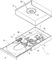
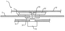
最初に、前提となるディスクドライブの分解斜視図を図1に示す。また、図2に、ディスクドライブのクランプ部によって光ディスク2(又はクリーニングディスク)が挟持された状態を拡大した断面図を示す。図1に示すように、光ディスクドライブは直方体形状のドライブ本体1と、ドライブ本体1の外側の光ディスクローディング位置21とドライブ本体内部の光ディスク信号読取位置22との間で光ディスク2(当然ながら通常のクリーニングディスクも同様)を搬送するスライドトレー3とを備えている。スライドトレー3は、ドライブ本体1に平行に相対移動可能であって、スライドトレー3の下側に一体的に形成されたラック31とこのラック31と係合する歯車機構4と図示しないモータなどによって駆動される。この実施の形態では、光ディスクローディング位置21において、光ディスク2のデータ記録面が下側になるように、光ディスク2はスライドトレー3に載置される。
First, FIG. 1 is an exploded perspective view of a premise disk drive. FIG. 2 is an enlarged cross-sectional view showing a state where the optical disk 2 (or cleaning disk) is clamped by the clamp portion of the disk drive. As shown in FIG. 1, the optical disk drive includes a rectangular parallelepiped drive main body 1 and an
光ディスク信号読取位置22には、光ディスク2の中央部を挟持して光ディスク2を回転させる一対のクランプ部5が設けられている。このクランプ部5は、スライドトレー3の下側に位置する支持板11に固着されたモータ14の回転軸の上端に取付けられた駆動板51と、ドライブ本体1の上蓋部12に回転可能に取付けられた軸に固着された回転板52とを含む。回転板52の中央部には、駆動板51と共に光ディスク2を挟持するための被駆動板53が設けられている。
The optical disk
駆動板51及び被駆動板53は、円形の形状を有しており、駆動板51及び被駆動板53の直径は、光ディスク2のデータ記録領域の直径より小さい。また、駆動板51及び被駆動板53の中央部には、突起が設けられている。突起は、光ディスク信号読取位置22に搬送されてきた光ディスク2の中央孔であるクランプ孔を挿通し、光ディスク2の位置決めをする役割を果たす。
The
駆動板51のモータ及びピックアップ部13が取付けられた略矩形の支持板11は、その長手方向の一端がドライブ本体1の底板に固着され、駆動板51のモータが固着された他端が、スライドトレー3の移動方向に対して直角方向に揺動できるように、ドライブ本体1に配置されている。支持板11は、歯車機構4と同期して揺動運動するように構成され、光ディスク信号読取位置22から光ディスクローディング位置21にスライドトレー3が移動しようとする時、駆動板51が、光ディスク2とは接触しない位置まで直角方向下側に揺動する。一方、光ディスク信号読取位置22までスライドトレー3がくると、光ディスク2を下側から位置決めして押し上げる。この押圧によって、駆動板51の突起が光ディスク2のクランプ孔を挿通し、突起を有する被駆動板53と係合する形で光ディスク2を挟持する。
The substantially
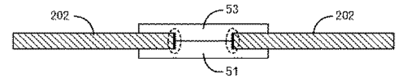
図3に、光ディスク2及びクランプ部5を拡大して模式的に示す。この図では、厚みについては特に強調して示されている。図3で太線で示し且つ点線で囲んだ、駆動板51及び被駆動板53の突起の側面と、光ディスク2のクランプ孔のとの接触により、ポリカーボネートの摩耗粉が発生することが分かっている。また、人は、通常光ディスク2のクランプ孔に指を通して光ディスク2を保持することが多いため、指に付着した摩耗粉などがそのうち光ディスク2の他の部分にも付着するようになる。従って、摩耗粉をできるだけクランプ部5に存在している時点で除去することが好ましい。
FIG. 3 schematically shows the
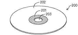
そこで、図4に示すようなクリーニングディスク200を採用する。本実施の形態に係るクリーニングディスク200は、クランプ孔203を有する基板202において、クランプ部5の駆動板51に接する面側であって、クランプ孔203の周辺部にリング状の粘着層201を設けたものである。粘着層201には、アクリル系粘着材、シリコーン系粘着材、ゴム系粘着材などを用いることができる。すなわち、材質に規制されるものではないが、ディスクドライブ1からの取り出し時に、粘着材成分がクランプ部5(チャッキング部分とも呼ぶ)に残ると好ましくないので、アクリル系粘着材、シリコーン系粘着材が好ましい。粘着層201の接着力は、90度剥離において0.3〜1N/25mmが望ましい。接着力が1N/25mmを超えると、クランプ部5からクリーニングディスク200が外れず、ドライブ本体1から取り出せず、接着力が0.3/25mmより小さいと異物の除去能力が小さくなる。
Therefore, a
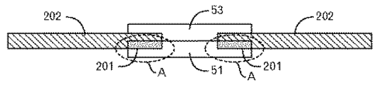
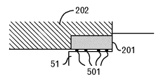
図5に、クリーニングディスク200がクランプ部5によって挟持されている状態の断面模式図を示す。この図においても、厚みについては特に強調されている。図5の点線楕円Aに示すように、基板202のうちクランプ部5の駆動板51と接する部分に粘着層201を設ける。そうすると、図6に模式的に示すように、クランプ部5の駆動板51に付着していたポリカーボネートなどの異物501は、粘着層201側に貼り付き、クリーニングディスク200を取り出す際には、駆動板51からはぎ取られることになる。すなわち、ポリカーボネートなどの異物501が、クリーニングディスク200によって、ディスクドライブ1から除去されることになる。
FIG. 5 shows a schematic cross-sectional view of the state in which the
粘着層201は、CD、DVD及びBDの規格に従う場合には、クリーニングディスク200の中心から、直径22.0mmから33.0mmまでの範囲に設けられる。より具体的には、クリーニングディスク200のクランプ孔203より外側で、駆動板51及び被駆動板53の直径までの範囲が好ましい。図7に示すように、駆動板51の外周から、粘着層201の外周までの距離L1は、0以上正の値であることが好ましい。また、通常の光ディスクにおけるデータ記録領域の最内周より内側で、クランプ孔203より外側の範囲である。このようにすれば、粘着層201がピックアップ部13に接触したりする事態を避けることができる。
The
なお、クランプ孔203の周辺部のディスク厚は、規格によれば1.2+0.20/−0.10mmとなっている。従って、粘着層201の厚みも、これよりも薄くなる。
The disc thickness around the clamp hole 203 is 1.2 + 0.20 / −0.10 mm according to the standard. Therefore, the thickness of the
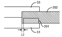
なお、図8に示すように、クランプ孔203に粘着層201を露出させる必要はない。すなわち、クランプ孔203から粘着層201の最内周までの距離L2は、0以上となり、正の値を有するようにしても良い。図3や図5、図7や図8は、厚み方向を強調しているため、大きな面積で接しているように見えるが、実際には上で述べたようなディスク厚しかないで、駆動板51及び被駆動板53の突起との接触面積はごくわずかだからである。
As shown in FIG. 8, it is not necessary to expose the
以上のような構成を採用することによって、ポリカーボネートの摩耗粉等の異物を、発生元箇所であるクランプ部5の駆動板51からはぎとって除去することができるようになる。
By adopting the configuration as described above, foreign matters such as polycarbonate abrasion powder can be peeled off from the
[実施例]
ポリカーボネートの摩耗粉と同様の粒径を有する粉末(例えば粒径分布0.05〜0.5mm、最頻値0.2mm)を人為的にまいた後に、クリーニングディスク200でクリーニングし、さらにその後通常の光ディスクでデータ記録を実施した場合の不良発生数を、以下で述べる実施例及び比較例について計数した。
[Example]
A powder having a particle size similar to that of polycarbonate wear powder (for example, particle size distribution 0.05 to 0.5 mm, mode value 0.2 mm) is artificially dispersed, then cleaned with a
ここでは、図9(A)に示すように、基板202の表面よりも粘着層201の表面が飛び出ている場合には、基板202の表面から粘着層201の表面までの高さを「正」とする。一方、図9(B)に示すように、基板202の表面よりも粘着層201の表面がくぼんでいる場合には、基板202の表面から粘着層201の表面までの高さを「負」とする。
Here, as shown in FIG. 9A, when the surface of the
そして実験結果を図10にまとめて示す。 The experimental results are summarized in FIG.
実施例1では、CDディスクの内周部分径20mmを0.1mm削り、削った部分に0.08mmの粘着層201(透明硬質塩化ビニール基材に、アクリル系粘着剤を使用したもの。以下同じ)を形成したクリーニングディスク200を用意した。すなわち、基板202の表面から粘着層201の表面までの高さが−0.02mmである。そして、上で述べた粉末を、DVDの記録再生装置(Panasonic社製 SW−9574。以下同じ。)におけるクランプ部5の駆動板51にまいた後、DVDの記録再生装置に対して、このようなクリーニングディスク200を装填し且つ取り出した。その後、出願人製のDVD−R10枚に対してデータ記録を実施した。そうすると、記録途中の停止や記録信号異常で再生できなかった不良発生数は0枚である。
In Example 1, the inner peripheral portion diameter 20 mm of the CD disc was cut by 0.1 mm, and a 0.08 mm pressure-sensitive adhesive layer 201 (a transparent hard vinyl chloride base material using an acrylic pressure-sensitive adhesive. The same applies hereinafter). The
実施例2では、CDディスクの内周部分径20mmを0.2mm削り、削った部分に0.08mmの粘着層201を形成したクリーニングディスク200を用意した。すなわち、基板202の表面から粘着層201の表面までの高さが−0.12mmである。そして、上で述べた粉末を、DVDの記録再生装置におけるクランプ部5の駆動板51にまいた後、DVDの記録再生装置に対して、このようなクリーニングディスク200を装填し且つ取り出した。その後、出願人製のDVD−R10枚に対してデータ記録を実施した。そうすると、記録途中の停止や記録信号異常で再生できなかった不良発生数は3枚である。以下で述べる比較例では10枚中8枚の高確率で不良となっているのに比較して、十分改善されているので、この実施例2は許容範囲である。
In Example 2, a
一方、比較例1では、クリーニングディスク200を用いない例である。すなわち、上で述べた粉末を、DVDの記録再生装置におけるクランプ部5の駆動板51にまいた後、クリーニングディスク200の装填及び取り出しを実施することなく、出願人製のDVD−R10枚に対してデータ記録を実施した。そうすると、記録途中の停止や記録信号異常で再生できなかった不良発生数は8枚である。
On the other hand, Comparative Example 1 is an example in which the
さらに、比較例2では、CDディスクの内周部分径20mmを削ることなく0.08mmの粘着層201を形成したクリーニングディスク200を用意した。すなわち、基板202の表面から粘着層201の表面までの高さが+0.08mmである。そうすると、DVDの記録再生装置では、このようなクリーニングディスク200を認識できなかった。これは、クランプ位置のズレによって、フォーカスサーボがかからなくなったものと思われる。これ以上、上記高さの値を大きくするとピックアップ部と接触する可能性もあり、好ましくない。
Furthermore, in Comparative Example 2, a
また、比較例3では、CDディスクの内周部分径20mmを0.3mm削り、削った部分に0.08mmの粘着層201を形成したクリーニングディスク200を用意した。すなわち、基板202の表面から粘着層201の表面までの高さが−0.22mmである。そして、上で述べた粉末を、DVDのある記録再生装置におけるクランプ部5の駆動板51にまいた後、DVDの記録再生装置に対して、このようなクリーニングディスク200を装填し且つ取り出した。その後、出願人製のDVD−R10枚に対してデータ記録を実施した。そうすると、記録途中の停止や記録信号異常で再生できなかった不良発生数は8枚である。これは、粘着層201の表面と基板202の表面との差が大きすぎて異物を圧着できていないためである。
In Comparative Example 3, a
以上のように、基板202の表面から粘着層201の表面までの高さの許容範囲は、−0.12mm以上−0.02mm以下である。但し、基板202の表面から粘着層201の表面までの高さが「正」の値を有する場合を全て否定するものではない。「負」の値を有する場合に比して、異物の除去効果が十分あることは自明であるから、クリーニングディスク200自体をディスクドライブ1が認識できる程度の値であれば、十分実用的である。
As described above, the allowable range of the height from the surface of the
以上、本実施の形態及び実施例について説明したが、本発明はこれに限定されるものではない。例えば、CD、DVD、BDを例に示したが、将来的に採用される他の規格のディスクについても、同様の機構でクランプするような場合には、同じように摩耗粉が発生するので、本発明によって対処可能である。 As mentioned above, although this Embodiment and the Example were described, this invention is not limited to this. For example, CD, DVD, and BD are shown as examples. However, when discs of other standards to be adopted in the future are clamped by the same mechanism, wear powder is generated in the same manner. It can be addressed by the present invention.
200 クリーニングディスク 201 粘着層
202 基板
200
Claims (3)
前記基板上において前記クランプ孔の周辺部に設けられている粘着層と、
を有するクリーニングディスクであって、
前記周辺部が、
前記クリーニングディスクが使用されるディスクドライブのクランプ部との接触範囲と同じ又は当該接触範囲より狭い範囲である
クリーニングディスク。 A substrate with a clamp hole in the center;
An adhesive layer provided on the periphery of the clamp hole on the substrate;
A cleaning disc having
The periphery is
A cleaning disk that is the same as or narrower than a contact range with a clamp portion of a disk drive in which the cleaning disk is used .
前記基板上において前記クランプ孔の周辺部に設けられている粘着層と、
を有するクリーニングディスクであって、
前記周辺部が、
前記クリーニングディスクが使用されるディスクドライブにおいてデータ再生可能なディスクのデータ記録領域より内側である
クリーニングディスク。 A substrate with a clamp hole in the center;
An adhesive layer provided on the periphery of the clamp hole on the substrate;
A cleaning disc having
The periphery is
In the disk drive where the cleaning disk is used, it is inside the data recording area of the disk where data can be reproduced.
Click leaning disk.
請求項1又は2記載のクリーニングディスク。 Surface of the adhesive layer is recessed from the surface of the substrate, and the surface of the substrate, the height difference between the surface of the adhesive layer, cleaning of claim 1 or 2, wherein a 0.12mm to 0.02mm disk.
Priority Applications (1)
| Application Number | Priority Date | Filing Date | Title |
|---|---|---|---|
| JP2009257476A JP5259555B2 (en) | 2009-11-10 | 2009-11-10 | Cleaning disc |
Applications Claiming Priority (1)
| Application Number | Priority Date | Filing Date | Title |
|---|---|---|---|
| JP2009257476A JP5259555B2 (en) | 2009-11-10 | 2009-11-10 | Cleaning disc |
Publications (2)
| Publication Number | Publication Date |
|---|---|
| JP2011103156A JP2011103156A (en) | 2011-05-26 |
| JP5259555B2 true JP5259555B2 (en) | 2013-08-07 |
Family
ID=44193433
Family Applications (1)
| Application Number | Title | Priority Date | Filing Date |
|---|---|---|---|
| JP2009257476A Expired - Fee Related JP5259555B2 (en) | 2009-11-10 | 2009-11-10 | Cleaning disc |
Country Status (1)
| Country | Link |
|---|---|
| JP (1) | JP5259555B2 (en) |
Family Cites Families (1)
| Publication number | Priority date | Publication date | Assignee | Title |
|---|---|---|---|---|
| JP2008305489A (en) * | 2007-06-07 | 2008-12-18 | Yutaka Kunikata | Dust removing disk |
-
2009
- 2009-11-10 JP JP2009257476A patent/JP5259555B2/en not_active Expired - Fee Related
Also Published As
| Publication number | Publication date |
|---|---|
| JP2011103156A (en) | 2011-05-26 |
Similar Documents
| Publication | Publication Date | Title |
|---|---|---|
| JP5065461B2 (en) | Optical information recording medium, method for manufacturing the same, and method for holding optical information recording medium | |
| CN1383553A (en) | Disk floating device | |
| CN100378846C (en) | CD drive | |
| JP5259555B2 (en) | Cleaning disc | |
| TWI362035B (en) | ||
| JP5019062B2 (en) | Disc tray, disc recording / reproducing apparatus, and disc medium separating method | |
| JP2007172727A (en) | Recording / playback device | |
| JP2006228327A (en) | Disk clamp mechanism provided with centering function | |
| JP2009230785A (en) | Disk rotation stabilization plate, disk recording/playback device, and disk medium separation method | |
| KR100930355B1 (en) | Optical disc drive | |
| JP4068621B2 (en) | Cleaner for optical information processing equipment | |
| KR200193753Y1 (en) | Optical disk | |
| JP4996564B2 (en) | Recording / reproducing apparatus and driving method thereof | |
| JP4032499B2 (en) | Optical disk device | |
| CN100423109C (en) | CD device | |
| JP4551033B2 (en) | Optical information recording medium initialization method and optical information recording medium initialization apparatus | |
| JP2001195713A (en) | Cleaner for disk player and method for cleaning disk player | |
| CN102129871A (en) | Optical disc drive | |
| JP2008305489A (en) | Dust removing disk | |
| JPH11219557A (en) | Optical disk holding device | |
| JP2006172536A (en) | Optical disk | |
| JP2003030884A (en) | Cleaning cartridge | |
| WO2003041078A1 (en) | Optical disk and method of chucking the optical disk | |
| JP2007200470A (en) | Information recording / reproducing apparatus and disk clamper | |
| CN1243592A (en) | Disc case |
Legal Events
| Date | Code | Title | Description |
|---|---|---|---|
| A621 | Written request for application examination |
Free format text: JAPANESE INTERMEDIATE CODE: A621 Effective date: 20120809 |
|
| A977 | Report on retrieval |
Free format text: JAPANESE INTERMEDIATE CODE: A971007 Effective date: 20130110 |
|
| A131 | Notification of reasons for refusal |
Free format text: JAPANESE INTERMEDIATE CODE: A131 Effective date: 20130122 |
|
| A521 | Request for written amendment filed |
Free format text: JAPANESE INTERMEDIATE CODE: A523 Effective date: 20130305 |
|
| TRDD | Decision of grant or rejection written | ||
| A01 | Written decision to grant a patent or to grant a registration (utility model) |
Free format text: JAPANESE INTERMEDIATE CODE: A01 Effective date: 20130409 |
|
| A61 | First payment of annual fees (during grant procedure) |
Free format text: JAPANESE INTERMEDIATE CODE: A61 Effective date: 20130424 |
|
| FPAY | Renewal fee payment (event date is renewal date of database) |
Free format text: PAYMENT UNTIL: 20160502 Year of fee payment: 3 |
|
| R150 | Certificate of patent or registration of utility model |
Free format text: JAPANESE INTERMEDIATE CODE: R150 |
|
| LAPS | Cancellation because of no payment of annual fees |