JP5259553B2 - Walking assist device - Google Patents
Walking assist device Download PDFInfo
- Publication number
- JP5259553B2 JP5259553B2 JP2009252845A JP2009252845A JP5259553B2 JP 5259553 B2 JP5259553 B2 JP 5259553B2 JP 2009252845 A JP2009252845 A JP 2009252845A JP 2009252845 A JP2009252845 A JP 2009252845A JP 5259553 B2 JP5259553 B2 JP 5259553B2
- Authority
- JP
- Japan
- Prior art keywords
- user
- joint
- link
- support member
- rigidity
- Prior art date
- Legal status (The legal status is an assumption and is not a legal conclusion. Google has not performed a legal analysis and makes no representation as to the accuracy of the status listed.)
- Expired - Fee Related
Links
Images


Classifications
-
- A—HUMAN NECESSITIES
- A61—MEDICAL OR VETERINARY SCIENCE; HYGIENE
- A61H—PHYSICAL THERAPY APPARATUS, e.g. DEVICES FOR LOCATING OR STIMULATING REFLEX POINTS IN THE BODY; ARTIFICIAL RESPIRATION; MASSAGE; BATHING DEVICES FOR SPECIAL THERAPEUTIC OR HYGIENIC PURPOSES OR SPECIFIC PARTS OF THE BODY
- A61H3/00—Appliances for aiding patients or disabled persons to walk about
- A61H3/008—Appliances for aiding patients or disabled persons to walk about using suspension devices for supporting the body in an upright walking or standing position, e.g. harnesses
-
- A—HUMAN NECESSITIES
- A61—MEDICAL OR VETERINARY SCIENCE; HYGIENE
- A61H—PHYSICAL THERAPY APPARATUS, e.g. DEVICES FOR LOCATING OR STIMULATING REFLEX POINTS IN THE BODY; ARTIFICIAL RESPIRATION; MASSAGE; BATHING DEVICES FOR SPECIAL THERAPEUTIC OR HYGIENIC PURPOSES OR SPECIFIC PARTS OF THE BODY
- A61H3/00—Appliances for aiding patients or disabled persons to walk about
-
- A—HUMAN NECESSITIES
- A63—SPORTS; GAMES; AMUSEMENTS
- A63B—APPARATUS FOR PHYSICAL TRAINING, GYMNASTICS, SWIMMING, CLIMBING, OR FENCING; BALL GAMES; TRAINING EQUIPMENT
- A63B23/00—Exercising apparatus specially adapted for particular parts of the body
- A63B23/035—Exercising apparatus specially adapted for particular parts of the body for limbs, i.e. upper or lower limbs, e.g. simultaneously
- A63B23/04—Exercising apparatus specially adapted for particular parts of the body for limbs, i.e. upper or lower limbs, e.g. simultaneously for lower limbs
-
- B—PERFORMING OPERATIONS; TRANSPORTING
- B25—HAND TOOLS; PORTABLE POWER-DRIVEN TOOLS; MANIPULATORS
- B25J—MANIPULATORS; CHAMBERS PROVIDED WITH MANIPULATION DEVICES
- B25J9/00—Program-controlled manipulators
- B25J9/0006—Exoskeletons, i.e. resembling a human figure
-
- A—HUMAN NECESSITIES
- A61—MEDICAL OR VETERINARY SCIENCE; HYGIENE
- A61H—PHYSICAL THERAPY APPARATUS, e.g. DEVICES FOR LOCATING OR STIMULATING REFLEX POINTS IN THE BODY; ARTIFICIAL RESPIRATION; MASSAGE; BATHING DEVICES FOR SPECIAL THERAPEUTIC OR HYGIENIC PURPOSES OR SPECIFIC PARTS OF THE BODY
- A61H2201/00—Characteristics of apparatus not provided for in the preceding codes
- A61H2201/01—Constructive details
- A61H2201/0165—Damping, vibration related features
-
- A—HUMAN NECESSITIES
- A61—MEDICAL OR VETERINARY SCIENCE; HYGIENE
- A61H—PHYSICAL THERAPY APPARATUS, e.g. DEVICES FOR LOCATING OR STIMULATING REFLEX POINTS IN THE BODY; ARTIFICIAL RESPIRATION; MASSAGE; BATHING DEVICES FOR SPECIAL THERAPEUTIC OR HYGIENIC PURPOSES OR SPECIFIC PARTS OF THE BODY
- A61H2201/00—Characteristics of apparatus not provided for in the preceding codes
- A61H2201/12—Driving means
- A61H2201/1207—Driving means with electric or magnetic drive
- A61H2201/1215—Rotary drive
-
- A—HUMAN NECESSITIES
- A61—MEDICAL OR VETERINARY SCIENCE; HYGIENE
- A61H—PHYSICAL THERAPY APPARATUS, e.g. DEVICES FOR LOCATING OR STIMULATING REFLEX POINTS IN THE BODY; ARTIFICIAL RESPIRATION; MASSAGE; BATHING DEVICES FOR SPECIAL THERAPEUTIC OR HYGIENIC PURPOSES OR SPECIFIC PARTS OF THE BODY
- A61H2201/00—Characteristics of apparatus not provided for in the preceding codes
- A61H2201/14—Special force transmission means, i.e. between the driving means and the interface with the user
- A61H2201/1436—Special crank assembly
-
- A—HUMAN NECESSITIES
- A61—MEDICAL OR VETERINARY SCIENCE; HYGIENE
- A61H—PHYSICAL THERAPY APPARATUS, e.g. DEVICES FOR LOCATING OR STIMULATING REFLEX POINTS IN THE BODY; ARTIFICIAL RESPIRATION; MASSAGE; BATHING DEVICES FOR SPECIAL THERAPEUTIC OR HYGIENIC PURPOSES OR SPECIFIC PARTS OF THE BODY
- A61H2201/00—Characteristics of apparatus not provided for in the preceding codes
- A61H2201/16—Physical interface with patient
- A61H2201/1602—Physical interface with patient kind of interface, e.g. head rest, knee support or lumbar support
- A61H2201/1623—Back
-
- A—HUMAN NECESSITIES
- A61—MEDICAL OR VETERINARY SCIENCE; HYGIENE
- A61H—PHYSICAL THERAPY APPARATUS, e.g. DEVICES FOR LOCATING OR STIMULATING REFLEX POINTS IN THE BODY; ARTIFICIAL RESPIRATION; MASSAGE; BATHING DEVICES FOR SPECIAL THERAPEUTIC OR HYGIENIC PURPOSES OR SPECIFIC PARTS OF THE BODY
- A61H2201/00—Characteristics of apparatus not provided for in the preceding codes
- A61H2201/16—Physical interface with patient
- A61H2201/1602—Physical interface with patient kind of interface, e.g. head rest, knee support or lumbar support
- A61H2201/1628—Pelvis
- A61H2201/1633—Seat
-
- A—HUMAN NECESSITIES
- A61—MEDICAL OR VETERINARY SCIENCE; HYGIENE
- A61H—PHYSICAL THERAPY APPARATUS, e.g. DEVICES FOR LOCATING OR STIMULATING REFLEX POINTS IN THE BODY; ARTIFICIAL RESPIRATION; MASSAGE; BATHING DEVICES FOR SPECIAL THERAPEUTIC OR HYGIENIC PURPOSES OR SPECIFIC PARTS OF THE BODY
- A61H2201/00—Characteristics of apparatus not provided for in the preceding codes
- A61H2201/16—Physical interface with patient
- A61H2201/1602—Physical interface with patient kind of interface, e.g. head rest, knee support or lumbar support
- A61H2201/1635—Hand or arm, e.g. handle
-
- A—HUMAN NECESSITIES
- A61—MEDICAL OR VETERINARY SCIENCE; HYGIENE
- A61H—PHYSICAL THERAPY APPARATUS, e.g. DEVICES FOR LOCATING OR STIMULATING REFLEX POINTS IN THE BODY; ARTIFICIAL RESPIRATION; MASSAGE; BATHING DEVICES FOR SPECIAL THERAPEUTIC OR HYGIENIC PURPOSES OR SPECIFIC PARTS OF THE BODY
- A61H2201/00—Characteristics of apparatus not provided for in the preceding codes
- A61H2201/16—Physical interface with patient
- A61H2201/1602—Physical interface with patient kind of interface, e.g. head rest, knee support or lumbar support
- A61H2201/164—Feet or leg, e.g. pedal
- A61H2201/1642—Holding means therefor
-
- A—HUMAN NECESSITIES
- A61—MEDICAL OR VETERINARY SCIENCE; HYGIENE
- A61H—PHYSICAL THERAPY APPARATUS, e.g. DEVICES FOR LOCATING OR STIMULATING REFLEX POINTS IN THE BODY; ARTIFICIAL RESPIRATION; MASSAGE; BATHING DEVICES FOR SPECIAL THERAPEUTIC OR HYGIENIC PURPOSES OR SPECIFIC PARTS OF THE BODY
- A61H2201/00—Characteristics of apparatus not provided for in the preceding codes
- A61H2201/16—Physical interface with patient
- A61H2201/1602—Physical interface with patient kind of interface, e.g. head rest, knee support or lumbar support
- A61H2201/165—Wearable interfaces
-
- A—HUMAN NECESSITIES
- A61—MEDICAL OR VETERINARY SCIENCE; HYGIENE
- A61H—PHYSICAL THERAPY APPARATUS, e.g. DEVICES FOR LOCATING OR STIMULATING REFLEX POINTS IN THE BODY; ARTIFICIAL RESPIRATION; MASSAGE; BATHING DEVICES FOR SPECIAL THERAPEUTIC OR HYGIENIC PURPOSES OR SPECIFIC PARTS OF THE BODY
- A61H2201/00—Characteristics of apparatus not provided for in the preceding codes
- A61H2201/16—Physical interface with patient
- A61H2201/1657—Movement of interface, i.e. force application means
- A61H2201/1676—Pivoting
-
- A—HUMAN NECESSITIES
- A61—MEDICAL OR VETERINARY SCIENCE; HYGIENE
- A61H—PHYSICAL THERAPY APPARATUS, e.g. DEVICES FOR LOCATING OR STIMULATING REFLEX POINTS IN THE BODY; ARTIFICIAL RESPIRATION; MASSAGE; BATHING DEVICES FOR SPECIAL THERAPEUTIC OR HYGIENIC PURPOSES OR SPECIFIC PARTS OF THE BODY
- A61H2201/00—Characteristics of apparatus not provided for in the preceding codes
- A61H2201/50—Control means thereof
- A61H2201/5007—Control means thereof computer controlled
-
- A—HUMAN NECESSITIES
- A61—MEDICAL OR VETERINARY SCIENCE; HYGIENE
- A61H—PHYSICAL THERAPY APPARATUS, e.g. DEVICES FOR LOCATING OR STIMULATING REFLEX POINTS IN THE BODY; ARTIFICIAL RESPIRATION; MASSAGE; BATHING DEVICES FOR SPECIAL THERAPEUTIC OR HYGIENIC PURPOSES OR SPECIFIC PARTS OF THE BODY
- A61H2201/00—Characteristics of apparatus not provided for in the preceding codes
- A61H2201/50—Control means thereof
- A61H2201/5058—Sensors or detectors
- A61H2201/5061—Force sensors
Landscapes
- Health & Medical Sciences (AREA)
- General Health & Medical Sciences (AREA)
- Physical Education & Sports Medicine (AREA)
- Life Sciences & Earth Sciences (AREA)
- Epidemiology (AREA)
- Pain & Pain Management (AREA)
- Rehabilitation Therapy (AREA)
- Animal Behavior & Ethology (AREA)
- Public Health (AREA)
- Veterinary Medicine (AREA)
- Engineering & Computer Science (AREA)
- Mechanical Engineering (AREA)
- Robotics (AREA)
- Orthopedic Medicine & Surgery (AREA)
- Rehabilitation Tools (AREA)
- Manipulator (AREA)
Description
この発明は歩行補助装置に関し、より詳しくは利用者の下半身に装着させてその歩行を補助する歩行補助装置における各部位の剛性の決定に関する。 The present invention relates to a walking assistance device, and more particularly to determination of rigidity of each part in a walking assistance device that is attached to a lower body of a user and assists the walking.
近年、利用者の歩行を補助する歩行補助装置としては、例えば下記の特許文献1記載の技術が知られている。
2. Description of the Related Art In recent years, for example, a technique described in
特許文献1記載の歩行補助装置にあっては、利用者を支持可能な支持部材と、利用者の足部を収容自在な靴部と、第1関節部を介して支持部材に連結されると共に、第2関節部を介して靴部に連結される脚リンクとを備え、利用者の体重の少なくとも一部を支持するアシスト力を生じて利用者の歩行を補助するように構成される。
In the walking assist device described in
特許文献1記載の歩行補助装置にあっては上記のように構成することで利用者の歩行を補助することができるが、装置の各部の剛性をどのように決定すべきかが明確でなかったため、利用者の受けるアシスト感において改善の余地があった。
In the walking assistance device described in
従って、この発明の目的は上記した課題を解決し、脚リンクを介して利用者の体重の少なくとも一部を支持するアシスト力を生じて歩行を補助すると共に、各部の剛性の決定を明確にして利用者の受けるアシスト感を向上させるようにした歩行補助装置を提供することにある。 Therefore, the object of the present invention is to solve the above-mentioned problems, generate an assist force that supports at least a part of the user's weight via the leg link, assist walking, and clarify the rigidity of each part. An object of the present invention is to provide a walking assist device that improves the feeling of assist received by a user.
上記した課題を解決するために、請求項1にあっては、着座した利用者を支持可能な支持部材と、利用者の足部を収容自在な靴部と、第1関節部を介して前記支持部材に連結される第1リンクと、第2関節部を介して前記靴部に連結される第2リンクと、前記第1リンクと第2リンクとを連結する第3関節部と、前記第1リンクと第2リンクを前記第3関節部を中心として相対変位させる駆動機構とを備え、利用者の体重の少なくとも一部を支持するアシスト力を生じて利用者の歩行を補助する歩行補助装置において、利用者が前記支持部材に支持されると共に、前記駆動機構によって前記第1リンクと第2リンクを前記第3関節部を中心として相対変位させる場合、利用者の尻部から前記第1関節部までの部位の剛性をK1[N/m]、前記第1関節部から前記第3関節部を介して連結される前記第2関節部までの部位の剛性をK2[N/m]、前記第2関節部から利用者の足までの部位の剛性をK31[N/m]とするとき、(K1+K31)<K2とする如く構成した。
In order to solve the above-described problem, in
請求項2にあっては、利用者が前記支持部材に支持される場合、前記第2関節部から床面までの部位の剛性をK32[N/m]とするとき、K1<K32とする如く構成した。 In the second aspect, if a Subscriber is supported by the supporting member, when the rigidity of the site to the floor from the second joint and K32 [N / m], and K1 <K32 It was configured as follows.
請求項1にあっては、着座した利用者を支持可能な支持部材と、利用者の足部を収容自在な靴部と、第1関節部を介して支持部材に連結される第1リンクと、第2関節部を介して靴部に連結される第2リンクと、第1リンクと第2リンクとを連結する第3関節部と、第1リンクと第2リンクを第3関節部を中心として相対変位させる駆動機構とを備え、利用者の体重の少なくとも一部を支持するアシスト力を生じて利用者の歩行を補助する歩行補助装置において、利用者が支持部材に支持されると共に、駆動機構によって第1リンクと第2リンクを第3関節部を中心として相対変位させる場合、利用者の尻部から第1関節部までの部位の剛性をK1[N/m]、第1関節部から第3関節部を介して連結される第2関節部までの部位の剛性をK2[N/m]、第2関節部から利用者の足までの部位の剛性をK31[N/m]とするとき、(K1+K31)<K2とする如く構成したので、第1関節部から第3関節部を介して連結される第2関節部までの部位以外の部位、即ち、装置の本体部以外の部位の重力方向における上下の変位に対してアシスト力が影響を受け難くなってアシスト力の制御精度が向上し、よって利用者の受けるアシスト感を向上させることができる。
In
請求項2にあっては、利用者が支持部材に支持される場合、第2関節部から床面までの部位の剛性をK32[N/m]とするとき、K1<K32とする如く構成したので、利用者の受けるアシスト感を向上させることができる。即ち、足側(靴部側)に作用する荷重は支持部材に作用する荷重に比して変動が大きいが、K1<K32とすることで、装置の重力方向における上下の振動量を小さく抑えることができ、よって利用者の受けるアシスト感を向上させることができる。また装置の重力方向における上下の振動量を小さく抑えることができることで、足踏みなどの動作において装置が重力方向において上下に振れるのを防止することができる。 In the second aspect, if a Subscriber is supported by the supporting lifting member, when the rigidity of the site to the floor from the second joint and K32 [N / m], as a K1 <K32 Since it comprised, the feeling of assistance which a user receives can be improved. That is, the load acting on the foot side (the shoe portion side) varies more than the load acting on the support member, but by setting K1 <K32, the amount of vertical vibration in the direction of gravity of the device can be kept small. Therefore, the sense of assistance received by the user can be improved. In addition, since the amount of vertical vibration in the direction of gravity of the device can be kept small, it is possible to prevent the device from swinging up and down in the direction of gravity during operations such as stepping.
以下、添付図面に即してこの発明に係る歩行補助装置を実施するための形態について説明する。 DESCRIPTION OF EMBODIMENTS Hereinafter, embodiments for carrying out a walking assist device according to the present invention will be described with reference to the accompanying drawings.
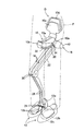
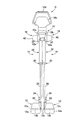
図1はこの発明の実施例に係る歩行補助装置の斜視図、図2はその側面図、図3はその正面図である。 1 is a perspective view of a walking assistance device according to an embodiment of the present invention, FIG. 2 is a side view thereof, and FIG. 3 is a front view thereof.
図1から図3を参照して説明すると、歩行補助装置Dは、利用者(人)Pに装着され、利用者Pが跨ぐように着座(跨座)することで利用者Pを支持可能な支持部材10と、利用者の左右の足部に装着される左右一対の靴部12と、支持部材10と左右一対の靴部12との間に設けられる、左右一対の脚リンク14と、駆動機構16を備え、支持部材10に設けられたベルト(図示せず)を介して利用者Pの下半身に装着されてその歩行を補助する。
If will be described with reference to FIG from Figure 1, the walking assist device D is mounted on the user (human) P, capable of supporting the user P by seating (Matagaza) so as to extend over the user
左右の脚リンク14はアルミ材からなり、それぞれ支持部材10に(人でいえば股関節に相当する)第1関節部20を介して連結される第1リンク(大腿リンク)22と、靴部12に(人でいえば足首関節に相当する)第2関節部24を介して連結される第2リンク(下腿リンク)26と、第1リンク22と第2リンク26とを連結する(人でいえば膝関節に相当する)第3関節部30とを備える。
The left and
脚リンク14の第1リンク22と第2リンク26は駆動機構16に連結され、第1リンク22と第2リンク26は駆動機構16により、第3関節部30を中心として(第3関節部30回りに)相対変位(駆動)させられる。
The
支持部材10は、利用者Pが跨座自在なサドル状のシート部10aと、シート部10aに隣接して配置されてシート部10aを支持する支持フレーム10bと、支持フレーム10bにおいてシート部10aの後端(利用者Pにとって)を超えて立ち上がり、利用者Pの腰が当接される腰当て部10cとを備える。腰当て部10cには利用者Pの把持可能に把持部(グリップ)10dが取り付けられる。
The
図2に良く示す如く、支持部材10の支持フレーム10bは、全体として前方(利用者Pに装着されたとき、その進行方向において)に傾斜するように構成される。シート部10aはクッション材から製作されると共に、支持フレーム10bと腰当て部10cは、シート部10aに比して剛性の高い素材から製作される。
As shown in FIG. 2, the
各脚リンク14と支持部材10を連結する第1関節部20は、支持部材10に固定される円弧状のガイドレール32と、ガイドレール32に係合されると共に、各脚リンク14の一端に固定されるスライダ34とからなる。ガイドレール32とスライダ34もアルミ材からなる。
The first
スライダ34には複数個のローラ36が取り付けられる。ローラ36はガイドレール32に形成された溝内に転動自在に収容され、よってスライダ34は図2に示す如く移動自在にガイドレール32に係合される。
A plurality of
即ち、脚リンク14は、ガイドレール32の曲率中心32aを中心として(揺動支点として)支持部材10の長手方向に揺動自在に構成される。またガイドレール32は支持部材10の腰当て部10cに、支持部材10の長手方向に配置された支軸32bに軸支され、支軸32bを中心として支持部材10の横方向に揺動自在に構成される。
That is, the
このように脚リンク14はガイドレール32の曲率中心32aを揺動支点として前後方向(利用者Pの進行方向において)に揺動自在に構成されることから、支持部材10に対して利用者Pの上半身の体重の作用点が揺動支点32aの前方にずれて支持部材10が前下がりに傾斜した場合、揺動支点32aが支持部材10の重力方向において上方に位置するため、体重の作用点は揺動支点32aの下方で後方に変位し、揺動支点32aと体重の作用点との前後方向距離が減少して支持部材10に対する回転モーメントも減少する。
As described above, the
次いで、体重作用点が揺動支点32aの真下まで変位したところで支持部材10に作用する回転モーメントは零になり、支持部材10は安定する。このように支持部材10が自動的に安定状態に収束するため、支持部材10が利用者Pの股下位置で前後方向にずれることがない。
Next, when the weight application point is displaced to just below the
また、ガイドレール32は揺動支点(支軸)32bを介して横方向(利用者Pの進行方向において)に揺動自在に構成されることから、脚リンク14を横方向に揺動させることができ、利用者Pは脚を自由に外転させることができる。
Further, since the
靴部12は、利用者Pの足部が収容自在な靴12aと、靴12aの内部に配置されて利用者Pの足が戴置可能なL字状(利用者Pの進行方向において前方から見たとき)のカーボン材からなる連結部材12bと、連結部材12bの底面上に配置されるウレタンゴムなどのゴム状弾性材からなる中敷12cとを備える。連結部材12bには各脚リンク14の第2リンク26が3軸構造の第2関節部24を介して連結される。
The
図4は駆動機構16と第1リンク22などの側面断面図である。
FIG. 4 is a side sectional view of the
駆動機構16は、第1リンク22の先端の付近に配置されるアクチュエータ(電動モータ)42と、アクチュエータ42の回転を減速機42aで減速して出力する出力軸42bと、出力軸42bに固定される駆動クランクアーム44と、第2リンク26に第3関節部30の関節軸30aと同心に固定された従動クランクアーム46とで構成される。
The
駆動クランクアーム44と従動クランクアーム46とは前記した第1リンク22で連結される。即ち、第1リンク22は、一端が駆動クランクアーム44に枢着部22bで、他端が従動クランクアーム46に枢着部22cで枢着される連結ロッド22aで回転自在に連結される。このように、第1リンク22は具体的には、リンク22と、駆動クランクアーム44と、連結ロッド22aと、従動クランクアーム46からなる4節機構から構成される。
The
図4に示す如く、第1リンク22は、その駆動クランクアーム44への枢着部22bと従動クランクアーム46への枢着部22cとを結ぶ線が、アクチュエータ42の出力軸42bと第3関節部30の関節軸30aとを結ぶ線に斜交するように配置される。第1リンク22のカバー22dの内部にはバッテリ50が収容され、アクチュエータ42などに動作用の電力を供給する。
As shown in FIG. 4, the
次いで、利用者Pの歩行を補助する歩行アシスト制御について説明する。尚、利用者Pは、遊脚期(脚の一方が接地し、他方が遊脚となる片脚支持期)と立脚期(両脚が接地する両脚支持期)を繰り返しつつ、歩行する。 Next, walking assist control for assisting the walking of the user P will be described. The user P walks while repeating the swing period (one leg support period in which one leg is grounded and the other is a free leg) and the stance period (both leg support period in which both legs are grounded).
靴部12において中敷12cの下面には前後一対の1軸の力センサ60が設けられ、利用者Pの足部の中趾節関節(MP関節)部分と踵部分とに作用する荷重に応じた出力を生じると共に、第2関節部24には2軸の力センサ62が組み込まれ、第2関節部24に作用する力(支持部材10と各脚リンク14の重量による力との合力)に応じた出力を生じる。
In the
上記したセンサ60,62の出力は、支持部材10の支持フレーム10bの内部に収納されたコントローラ64に送られる。コントローラ64はCPU,ROM,RAMおよび入出力I/Oを備えたマイクロコンピュータからなり、利用者Pの歩行を補助するアシスト力を発生するアシスト制御を実行する。
The outputs of the above-described
即ち、コントローラ64は、予め設定されるアシスト力の設定値に、圧力センサ60の出力から算出された利用者Pの両足部に作用する全荷重に対する各足部の荷重の割合を乗算し、よって得た積を各脚リンク14で発生すべきアシスト力の目標値とする。例えば装置Dの荷重(重量)を60[N]、アシスト力を30[N]とすると、アシスト力の設定値は90[N]となる。
That is, the
アシスト力は、図2において第1関節部20における脚リンク14の前後方向の揺動支点32aと第2関節部24における脚リンク14の前後方向の揺動支点とを結ぶ線(以下「基準線」といい、L1で示す)の上に作用することから、コントローラ64は、力センサ62の出力に基づき、基準線L1上に作用する実際のアシスト力を検出し、検出された実際のアシスト力が目標値となるように、PD制御などのフィードバック制御を通じて駆動機構16の動作、より具体的にはアクチュエータ42の通電を制御する。
In FIG. 2, the assist force is a line (hereinafter referred to as “reference line”) connecting a
より具体的には、後で図6に示す如く、コントローラ64は、利用者Pが支持部材10のシート部10aに着座して支持されるとき、駆動機構16のアクチュエータ42を駆動して脚リンク14の第1リンク22と第2リンク26を第3関節部30の関節軸30aを中心として相対変位させ、利用者Pの体重の少なくとも一部を支持する支持力、即ち、アシスト力を生じさせて利用者Pの歩行を補助する。
More specifically, as shown in FIG. 6 later, when the user P is seated and supported by the
脚リンク14で発生されたアシスト力は支持部材10を通じて利用者Pの体幹に伝達され、利用者Pの脚に作用する荷重を軽減して歩行を補助する。利用者Pとしては、工場などで立ち作業する作業者なども予定される。
The assist force generated by the
この実施例に係る歩行補助装置Dにおいて特徴的なことは、装置Dの各部の剛性の決定を明確にして利用者の受けるアシスト感を向上させるように構成したことにある。 A characteristic feature of the walking assistance device D according to this embodiment is that the determination of the rigidity of each part of the device D is clarified to improve the sense of assistance received by the user.
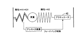
以下、それについて説明すると、図5(a)は図1などに示す装置Dを簡略化して示す説明図、図5(b)はそれをさらに簡略化して示す説明図、図6は前記したアシスト制御を示すブロック図、図7は靴部12などの変位のステップ入力に対するアシスト力の応答を示すシミューレーションデータである。
In the following, this will be described. FIG. 5A is a simplified illustration of the device D shown in FIG. 1, etc., FIG. 5B is a simplified illustration of the device D, and FIG. FIG. 7 is a simulation data showing the response of the assist force to the step input of the displacement of the
図5に示す如く、この実施例に係る歩行補助装置Dにおいては、利用者Pが支持部材10に支持される(着座する)とき、利用者P、より正確にはその尻部から第1関節部20までの部位の剛性をK1[N/m]、第1関節部20から第3関節部30を介して連結される第2関節部24までの部位の剛性をK2[N/m]、第2関節部から利用者Pの足までの部位の剛性をK31[N/m]とするとき、(K1+K31)<K2とする如く構成した。
As shown in FIG. 5, in the walking assist device D according to this embodiment, when the user P is supported (sit down) on the
図5において、上側の装置―骨盤連結部の剛性K1は具体的には支持部材10のシート部10aおよび(平均的な)利用者Pの尻部などの剛性を、下側の装置―床面または利用者Pの足までの剛性K31,K32は具体的には連結部材12b、中敷12c、利用者の足などの剛性を意味する。
In FIG. 5, the rigidity K1 of the upper device-pelvic joint is specifically the rigidity of the
また、この実施例に係る歩行補助装置Dにおいては、利用者P、より正確にはその重心位置から第1関節部20までの部位の剛性をK1[N/m]、第2関節部24から床面までの部位の剛性、より正確には立脚期における第2関節部24から床面(あるいは地面)までの部位の剛性をK32[N/m]とするとき、K1<K32とする如く構成した。
Further, in the walking assist device D according to this embodiment, the rigidity of the part from the user P, more precisely the position of the center of gravity to the first joint 20 is K1 [N / m], and the second joint 24 is used. When the rigidity of the part to the floor surface, more precisely, the rigidity of the part from the second
尚、図5に示すように、剛性Knはバネ定数、即ち、バネに作用する荷重[N]とそれによって生じるたわみ[m]を意味する。また、図5において利用者Pの骨盤までの硬さなどは利用者個々により異なるので、実験などを通じて得た平均的な値を使用する。 As shown in FIG. 5, the stiffness Kn means a spring constant, that is, a load [N] acting on the spring and a deflection [m] caused thereby. In FIG. 5, the hardness of the user P up to the pelvis and the like varies depending on the individual user, so an average value obtained through an experiment or the like is used.
図7は、図6に示す構成において、装置Dの上下の剛性の合算値(K1+K31)と装置Dの本体部の剛性K2の比を1:2あるいは2:1としたとき、本体部以外の部位、即ち、利用者の足あるいは利用者の重心位置の変位のステップ入力に対するアシスト力の応答を示すシミューレーションデータである。アシスト力は、図6の構成で得られる値を示す。 FIG. 7 shows the configuration shown in FIG. 6, when the ratio of the sum of the upper and lower stiffnesses of the device D (K1 + K31) and the stiffness K2 of the main body of the device D is 1: 2 or 2: 1. It is the simulation data which shows the response of the assist force with respect to the step input of the displacement of the part, that is, the user's foot or the user's center of gravity. The assist force indicates a value obtained with the configuration of FIG.
同図から明らかな如く、装置Dの上下の剛性の合算値と本体部の剛性の比を2:1とすると、アシスト力が大きく変動するが、1:2とすると、アシスト力の変動は小さくなる。従って、両者の比を1:2あるいはその付近に設定することで、本体部以外の部位、即ち、利用者Pの足あるいは利用者Pの重心位置などを微小に変動させても、アシスト力が影響を受け難くなってアシスト力の制御精度が向上し、よって利用者Pの受けるアシスト感を向上させることができる。 As is clear from the figure, when the ratio of the sum of the upper and lower stiffnesses of the device D and the stiffness of the main body is 2: 1, the assist force varies greatly, but when the ratio is 1: 2, the assist force variation is small. Become. Therefore, by setting the ratio of the two to 1: 2 or the vicinity thereof, the assist force can be obtained even if the part other than the main body, that is, the position of the user P's foot or the position of the center of gravity of the user P is minutely changed. It becomes difficult to be influenced, and the control accuracy of the assist force is improved, so that the sense of assist received by the user P can be improved.
上記した如く、この実施例にあっては、着座した利用者Pを支持可能な支持部材10と、利用者Pの足部を収容自在な靴部12と、第1関節部20を介して前記支持部材10に連結される第1リンク(大腿リンク)22と、第2関節部24を介して前記靴部12に連結される第2リンク(下腿リンク)26と、前記第1リンク22と第2リンク26とを連結する第3関節部30と、前記第1リンクと第2リンクを前記第3関節部を中心として相対変位させる駆動機構(アクチュエータ42、出力軸42b、駆動クランクアーム44、従動クランクアーム46)16とを備え、利用者Pの体重の少なくとも一部を支持するアシスト力を生じて利用者の歩行を補助する歩行補助装置Dにおいて、利用者Pが前記支持部材10に支持されると共に、前記駆動機構16によって前記第1リンク22と第2リンク26を前記第3関節部30を中心として相対変位させる場合、利用者Pの尻部、より正確には利用者Pの重心位置から前記第1関節部20までの部位の剛性(換言すれば前記第1関節部20より重力方向において上端側の剛性)をK1[N/m]、前記第1関節部20から前記第3関節部30を介して連結される前記第2関節部24までの部位の剛性をK2[N/m]、前記第2関節部24から利用者Pの足までの部位の剛性(換言すれば前記第2関節部24より重力方向において下端側の剛性)をK31[N/m]とするとき、(K1+K31)<K2とする如く構成、換言すれば、装置Dの本体部の剛性K2に対して装置Dの重力方向における上下端側の部位、換言すれば利用者Pに近い側の部位の剛性K1+K31を小さく、即ち、柔らかくしたので、装置Dの本体部以外の部位の変位に対してアシスト力が影響を受け難くなってアシスト力の制御精度が向上し、よって利用者Pの受けるアシスト感を向上させることができる。
As described above, in this embodiment, the
特に、装置Dの重力方向における上下の剛性K1,K31の合算値と本体部の剛性K2の比を1:2あるいはその近傍とするとき、装置Dの本体部以外の部位の変位に対してアシスト力が影響を受け難いようにすることができる。 In particular, when the ratio of the sum of the upper and lower stiffnesses K1 and K31 in the direction of gravity of the device D and the stiffness K2 of the main body is set to 1: 2 or in the vicinity thereof, the device D assists in displacement of parts other than the main body. Forces can be made less susceptible.
また、利用者Pが前記支持部材10に支持される場合、前記第2関節部24から床面までの部位の剛性をK32[N/m]とするとき、K1<K32とする如く構成したので、利用者Pの受けるアシスト感を向上させることができる。
Also, if a Subscriber P is supported by the supporting
即ち、足側(靴部12側)に作用する荷重は支持部材10に作用する荷重に比して変動が大きいが、K1<K32、換言すれば重力方向において上側より下側の接地する側の足の剛性を大きく、即ち、固くすることで、装置Dの重力方向における上下の振動量を小さく抑えることができ、よって利用者Pの受けるアシスト感を向上させることができる。また装置Dの重力方向における上下の振動量を小さく抑えることができることで、足踏みなどの動作において装置Dが重力方向において上下に振れるのを防止することができる。
That is, the load acting on the foot side (the
他方、装置Dの重力方向における上側は下側より剛性を小さく、即ち、柔らかくすることで、利用者Pに支持部材10を通じて柔らかいアシスト感を与えることができ、それによってもアシスト感を一層向上させることができる。
On the other hand, the upper side of the apparatus D in the direction of gravity is lower in rigidity than the lower side, that is, by making it softer, it is possible to give the user P a soft assist feeling through the
尚、この発明を実施例から説明したが、この発明は実施例に限定されるものではなく、種々の変形が可能である。例えば、支持部材10も着座可能な構造に限定されるものではなく、例えば特開2006−187348号公報に開示されるように、ベルトを用いる構造であっても良い。
In addition, although this invention was demonstrated from the Example, this invention is not limited to an Example, A various deformation | transformation is possible. For example, the
D 歩行補助装置、10 支持部材、10a シート部、10b 支持フレーム、10c 腰当て部、10d 把持部、12 靴部、12a 靴、12b 連結部材、12c 中敷、14 脚リンク、16 駆動機構、20 第1関節部(関節部)、22 第1リンク、24 第2関節部、26 第2リンク、30 第3関節部、32 ガイドレール、32a 曲率中心(揺動支点)、32b 支軸(揺動支点)、34 スライダ、36 ローラ、42 アクチュエータ、42a 減速機、42b 出力軸、44 駆動クランクアーム、46 従動クランクアーム、50 バッテリ、60,62 力センサ、64 コントローラ D Walking assist device, 10 support member, 10a seat portion, 10b support frame, 10c waist rest portion, 10d gripping portion, 12 shoe portion, 12a shoe, 12b connecting member, 12c insole, 14 leg link, 16 drive mechanism, 20 1st joint part (joint part), 22 1st link, 24 2nd joint part, 26 2nd link, 30 3rd joint part, 32 guide rail, 32a curvature center (swinging fulcrum), 32b supporting shaft (swinging) Fulcrum), 34 slider, 36 roller, 42 actuator, 42a speed reducer, 42b output shaft, 44 drive crank arm, 46 driven crank arm, 50 battery, 60, 62 force sensor, 64 controller
Claims (2)
Priority Applications (1)
| Application Number | Priority Date | Filing Date | Title |
|---|---|---|---|
| JP2009252845A JP5259553B2 (en) | 2008-11-06 | 2009-11-04 | Walking assist device |
Applications Claiming Priority (3)
| Application Number | Priority Date | Filing Date | Title |
|---|---|---|---|
| JP2008285947 | 2008-11-06 | ||
| JP2008285947 | 2008-11-06 | ||
| JP2009252845A JP5259553B2 (en) | 2008-11-06 | 2009-11-04 | Walking assist device |
Publications (2)
| Publication Number | Publication Date |
|---|---|
| JP2010131382A JP2010131382A (en) | 2010-06-17 |
| JP5259553B2 true JP5259553B2 (en) | 2013-08-07 |
Family
ID=42152894
Family Applications (1)
| Application Number | Title | Priority Date | Filing Date |
|---|---|---|---|
| JP2009252845A Expired - Fee Related JP5259553B2 (en) | 2008-11-06 | 2009-11-04 | Walking assist device |
Country Status (5)
| Country | Link |
|---|---|
| US (1) | US8591438B2 (en) |
| JP (1) | JP5259553B2 (en) |
| KR (1) | KR101321801B1 (en) |
| DE (1) | DE112009002665B4 (en) |
| WO (1) | WO2010053086A1 (en) |
Families Citing this family (11)
| Publication number | Priority date | Publication date | Assignee | Title |
|---|---|---|---|---|
| JP5879976B2 (en) * | 2011-11-30 | 2016-03-08 | 大日本印刷株式会社 | Operation assist device and program for operation assist control |
| JP5882696B2 (en) * | 2011-11-30 | 2016-03-09 | 大日本印刷株式会社 | Operation assist device and program for operation assist control |
| JP6483081B2 (en) | 2013-03-14 | 2019-03-13 | エクソ・バイオニクス,インコーポレーテッド | Non-human hip position for exoskeleton |
| JP5755313B2 (en) | 2013-11-11 | 2015-07-29 | 株式会社アスコ | Programmable display and control method |
| KR102186859B1 (en) | 2014-01-09 | 2020-12-04 | 삼성전자주식회사 | a walking assist device and a method for controlling the the walking assist device |
| KR102360100B1 (en) * | 2014-03-21 | 2022-02-08 | 완더크래프트 | Exoskeleton comprising a foot structure |
| JP2015208795A (en) * | 2014-04-24 | 2015-11-24 | パナソニック株式会社 | Operation assisting device |
| US10426637B2 (en) | 2015-05-11 | 2019-10-01 | The Hong Kong Polytechnic University | Exoskeleton ankle robot |
| EP3572059B1 (en) | 2017-01-19 | 2021-11-17 | Panasonic Intellectual Property Management Co., Ltd. | Device for preventing falls when walking, control device, control method, and program |
| EP3572060B1 (en) | 2017-01-19 | 2021-12-15 | Panasonic Intellectual Property Management Co., Ltd. | Device for preventing falls when walking, control device, control method, and program |
| KR102663218B1 (en) * | 2019-04-04 | 2024-05-03 | 현대자동차주식회사 | Wearable chair |
Family Cites Families (20)
| Publication number | Priority date | Publication date | Assignee | Title |
|---|---|---|---|---|
| FR2506604A1 (en) | 1981-06-01 | 1982-12-03 | Salort Guy | EXTERNAL VERTICAL AND MARKET STATION APPARATUS FOR DISABLED MOTORS OF THE LOWER LIMBS |
| JP2819353B2 (en) * | 1990-09-28 | 1998-10-30 | 本田技研工業株式会社 | Walking control device for legged mobile robot |
| US5432417A (en) * | 1992-04-30 | 1995-07-11 | Honda Giken Kogyo Kabushiki Kaisha | Locomotion control system for legged mobile robot |
| JPH07104856A (en) * | 1993-10-01 | 1995-04-21 | Fanuc Ltd | Vibration control method |
| JPH07328965A (en) * | 1994-06-03 | 1995-12-19 | Toyota Motor Corp | Damping control method, natural vibration period measuring method, and damping control device |
| EP1053835B1 (en) * | 1997-01-31 | 2006-12-27 | Honda Giken Kogyo Kabushiki Kaisha | Leg type mobile robot control apparatus |
| DE60131377T2 (en) * | 2000-03-29 | 2008-09-04 | Massachusetts Institute Of Technology, Cambridge | SPEED ADAPTED AND PATIENT ATTACHED KNEE PROSTHESIS |
| US7650204B2 (en) * | 2001-06-29 | 2010-01-19 | Honda Motor Co., Ltd. | Active control of an ankle-foot orthosis |
| US7623944B2 (en) * | 2001-06-29 | 2009-11-24 | Honda Motor Co., Ltd. | System and method of estimating joint loads in a three-dimensional system |
| US7684896B2 (en) * | 2001-06-29 | 2010-03-23 | Honda Motor Co., Ltd. | System and method of estimating joint loads using an approach of closed form dynamics |
| JP2006087533A (en) * | 2004-09-22 | 2006-04-06 | Honda Motor Co Ltd | Lumbar support for walking assist device |
| JP4344314B2 (en) | 2004-12-28 | 2009-10-14 | 本田技研工業株式会社 | Weight relief assist device and weight relief assist program |
| US7313463B2 (en) * | 2005-03-31 | 2007-12-25 | Massachusetts Institute Of Technology | Biomimetic motion and balance controllers for use in prosthetics, orthotics and robotics |
| US20070123997A1 (en) * | 2005-03-31 | 2007-05-31 | Massachusetts Institute Of Technology | Exoskeletons for running and walking |
| KR100856844B1 (en) * | 2005-05-27 | 2008-09-05 | 혼다 기켄 고교 가부시키가이샤 | Walking assisting device |
| JP4588666B2 (en) * | 2005-05-27 | 2010-12-01 | 本田技研工業株式会社 | Control device and control program for walking assist device |
| JP4641225B2 (en) | 2005-07-19 | 2011-03-02 | 本田技研工業株式会社 | Walking assist device |
| JP4617496B2 (en) * | 2005-07-22 | 2011-01-26 | トヨタ自動車株式会社 | Auxiliary device |
| US7578799B2 (en) * | 2006-06-30 | 2009-08-25 | Ossur Hf | Intelligent orthosis |
| JP4666644B2 (en) * | 2006-07-12 | 2011-04-06 | 本田技研工業株式会社 | Control device for walking aids |
-
2009
- 2009-11-04 KR KR1020117009179A patent/KR101321801B1/en not_active Expired - Fee Related
- 2009-11-04 WO PCT/JP2009/068814 patent/WO2010053086A1/en not_active Ceased
- 2009-11-04 JP JP2009252845A patent/JP5259553B2/en not_active Expired - Fee Related
- 2009-11-04 US US13/127,877 patent/US8591438B2/en not_active Expired - Fee Related
- 2009-11-04 DE DE112009002665.6T patent/DE112009002665B4/en not_active Expired - Fee Related
Also Published As
| Publication number | Publication date |
|---|---|
| JP2010131382A (en) | 2010-06-17 |
| WO2010053086A1 (en) | 2010-05-14 |
| US8591438B2 (en) | 2013-11-26 |
| DE112009002665T5 (en) | 2013-04-04 |
| DE112009002665B4 (en) | 2017-11-23 |
| KR20110074876A (en) | 2011-07-04 |
| US20110224586A1 (en) | 2011-09-15 |
| KR101321801B1 (en) | 2013-10-28 |
Similar Documents
| Publication | Publication Date | Title |
|---|---|---|
| JP5259553B2 (en) | Walking assist device | |
| US7731673B2 (en) | Walking assisting device | |
| CN101119696B (en) | Walking assisting device | |
| US8114034B2 (en) | Walking assisting device | |
| JP4666644B2 (en) | Control device for walking aids | |
| US8118763B2 (en) | Walking assist device | |
| US20090014042A1 (en) | Walk assistance device | |
| US7731674B2 (en) | Walking assistance device | |
| JP4641225B2 (en) | Walking assist device | |
| JP2008012224A (en) | Walking assist device | |
| EP1905407B1 (en) | Walking assistance device | |
| JP5841787B2 (en) | Wearable motion support device | |
| JP2014068866A (en) | Walking support device and walking support program | |
| JP5137704B2 (en) | Control device for walking assist device | |
| US8083702B2 (en) | Walking assistance device | |
| JPWO2018179431A1 (en) | Assistance device | |
| JP4387996B2 (en) | Walking assist device | |
| JP5285576B2 (en) | Walking assist device | |
| JP4724059B2 (en) | Walking assist device | |
| JP5484925B2 (en) | Guide mechanism and walking assist device | |
| US20110021330A1 (en) | Exercise aiding apparatus | |
| JP5356840B2 (en) | Walking assist device | |
| JP2014184087A (en) | Support device and support program |
Legal Events
| Date | Code | Title | Description |
|---|---|---|---|
| A621 | Written request for application examination |
Free format text: JAPANESE INTERMEDIATE CODE: A621 Effective date: 20111124 |
|
| A521 | Request for written amendment filed |
Free format text: JAPANESE INTERMEDIATE CODE: A523 Effective date: 20120518 |
|
| A131 | Notification of reasons for refusal |
Free format text: JAPANESE INTERMEDIATE CODE: A131 Effective date: 20130123 |
|
| A521 | Request for written amendment filed |
Free format text: JAPANESE INTERMEDIATE CODE: A523 Effective date: 20130318 |
|
| TRDD | Decision of grant or rejection written | ||
| A01 | Written decision to grant a patent or to grant a registration (utility model) |
Free format text: JAPANESE INTERMEDIATE CODE: A01 Effective date: 20130410 |
|
| A61 | First payment of annual fees (during grant procedure) |
Free format text: JAPANESE INTERMEDIATE CODE: A61 Effective date: 20130424 |
|
| FPAY | Renewal fee payment (event date is renewal date of database) |
Free format text: PAYMENT UNTIL: 20160502 Year of fee payment: 3 |
|
| R150 | Certificate of patent or registration of utility model |
Ref document number: 5259553 Country of ref document: JP Free format text: JAPANESE INTERMEDIATE CODE: R150 Free format text: JAPANESE INTERMEDIATE CODE: R150 |
|
| LAPS | Cancellation because of no payment of annual fees |