JP5259503B2 - Projection optical system and projection display device using the same - Google Patents
Projection optical system and projection display device using the same Download PDFInfo
- Publication number
- JP5259503B2 JP5259503B2 JP2009143689A JP2009143689A JP5259503B2 JP 5259503 B2 JP5259503 B2 JP 5259503B2 JP 2009143689 A JP2009143689 A JP 2009143689A JP 2009143689 A JP2009143689 A JP 2009143689A JP 5259503 B2 JP5259503 B2 JP 5259503B2
- Authority
- JP
- Japan
- Prior art keywords
- lens
- optical system
- projection
- light
- projection lens
- Prior art date
- Legal status (The legal status is an assumption and is not a legal conclusion. Google has not performed a legal analysis and makes no representation as to the accuracy of the status listed.)
- Active
Links
Images


Classifications
-
- G—PHYSICS
- G03—PHOTOGRAPHY; CINEMATOGRAPHY; ANALOGOUS TECHNIQUES USING WAVES OTHER THAN OPTICAL WAVES; ELECTROGRAPHY; HOLOGRAPHY
- G03B—APPARATUS OR ARRANGEMENTS FOR TAKING PHOTOGRAPHS OR FOR PROJECTING OR VIEWING THEM; APPARATUS OR ARRANGEMENTS EMPLOYING ANALOGOUS TECHNIQUES USING WAVES OTHER THAN OPTICAL WAVES; ACCESSORIES THEREFOR
- G03B33/00—Colour photography, other than mere exposure or projection of a colour film
- G03B33/10—Simultaneous recording or projection
- G03B33/12—Simultaneous recording or projection using beam-splitting or beam-combining systems, e.g. dichroic mirrors
-
- G—PHYSICS
- G03—PHOTOGRAPHY; CINEMATOGRAPHY; ANALOGOUS TECHNIQUES USING WAVES OTHER THAN OPTICAL WAVES; ELECTROGRAPHY; HOLOGRAPHY
- G03B—APPARATUS OR ARRANGEMENTS FOR TAKING PHOTOGRAPHS OR FOR PROJECTING OR VIEWING THEM; APPARATUS OR ARRANGEMENTS EMPLOYING ANALOGOUS TECHNIQUES USING WAVES OTHER THAN OPTICAL WAVES; ACCESSORIES THEREFOR
- G03B21/00—Projectors or projection-type viewers; Accessories therefor
- G03B21/14—Details
- G03B21/20—Lamp housings
- G03B21/2073—Polarisers in the lamp house
-
- G—PHYSICS
- G03—PHOTOGRAPHY; CINEMATOGRAPHY; ANALOGOUS TECHNIQUES USING WAVES OTHER THAN OPTICAL WAVES; ELECTROGRAPHY; HOLOGRAPHY
- G03B—APPARATUS OR ARRANGEMENTS FOR TAKING PHOTOGRAPHS OR FOR PROJECTING OR VIEWING THEM; APPARATUS OR ARRANGEMENTS EMPLOYING ANALOGOUS TECHNIQUES USING WAVES OTHER THAN OPTICAL WAVES; ACCESSORIES THEREFOR
- G03B21/00—Projectors or projection-type viewers; Accessories therefor
- G03B21/14—Details
- G03B21/20—Lamp housings
- G03B21/208—Homogenising, shaping of the illumination light
Landscapes
- Physics & Mathematics (AREA)
- General Physics & Mathematics (AREA)
- Lenses (AREA)
- Projection Apparatus (AREA)
Description
本発明は、反射型ライトバルブに表示された画像をスクリーン上に拡大投映する投写光学系、およびこれを搭載した投写型表示装置に関し、特に、極めて小型で携帯性に優れ、光源の輝度も比較的小さい投写光学系および投写型表示装置に関する。 The present invention relates to a projection optical system that magnifies and projects an image displayed on a reflective light valve on a screen, and a projection display device equipped with the projection optical system. The present invention relates to a small projection optical system and a projection display device.
近年、プロジェクタにおいて、携帯性に優れたハンディータイプのものが求められている。
そのようなハンディータイプのものの中でも、プロジェクタを懐中電灯やペンライトのように片手で把持し、所望する場所(例えば、壁や天井等)に投写することができれば便利である。
In recent years, a handy type projector having excellent portability has been demanded.
Among such handy types, it is convenient if the projector can be held with one hand like a flashlight or penlight and projected onto a desired place (for example, a wall or a ceiling).
ところで、プロジェクタに搭載されるライトバルブとして、反射型液晶表示素子(LCOS)やDMD(デジタル・マイクロ・デバイス)等の反射型ライトバルブが知られている。反射型ライトバルブは、透過型のものよりも開口率を増大させることができ、光量変換の効率化という利点を有するばかりではなく、装置のコンパクト化を促進し得る点でも有用である。 By the way, reflective light valves such as a reflective liquid crystal display element (LCOS) and a DMD (digital micro device) are known as light valves mounted on a projector. The reflective light valve can increase the aperture ratio as compared with the transmissive type, and has an advantage of improving the efficiency of light quantity conversion, and is also useful in that the device can be made compact.
一方、このような投写光学系の配置としては、一般に、投写レンズと反射型ライトバルブの間に偏光分離部としてのPBS(偏光分離プリズム)を配置し、光源部からの照明光はPBSを介して反射型ライトバルブに入射せしめ、この反射型ライトバルブからの変調光は、上記PBSにおいて上記照明光と光路分離し、投写レンズを用いてスクリーン方向に投写せしめるようにしたものが知られている。 On the other hand, as an arrangement of such a projection optical system, generally, a PBS (polarization separation prism) as a polarization separation unit is disposed between the projection lens and the reflective light valve, and illumination light from the light source unit passes through the PBS. It is known that light is incident on a reflective light valve, and the modulated light from the reflective light valve is separated from the illumination light in the PBS and projected in the screen direction using a projection lens. .
しかしながら、このような投写光学系では、上記PBSが入射角度特性を有しており、偏光分離面への光入射角度が範囲を有していると、それに応じて輝度むらや色むら等の不都合が発生することから、PBSにはテレセントリックな状態で照明光を入射させることが必要となり、投写レンズの縮小側をテレセントリックな状態とし得る構成とした上で、PBSおよび反射型ライトバルブを配置する必要があった。 However, in such a projection optical system, the PBS has an incident angle characteristic, and if the light incident angle on the polarization separation surface has a range, inconveniences such as luminance unevenness and color unevenness. Therefore, it is necessary to make illumination light incident on the PBS in a telecentric state, and it is necessary to arrange the PBS and the reflective light valve after making the reduction side of the projection lens telecentric. was there.
このような従来の投写光学系を搭載した投写表示装置の一例を図16に示す。すなわち、この3色LED光源111a〜c、ダイクロイックミラー112a、b、光量均一化手段としてのフライアイインテグレータ113a、b、照明光を、いずれかの直線偏光(P偏光またはS偏光)に揃える櫛型フィルタ114、および1対のフィールドレンズ(コンデンサレンズ)115a、115bからなる照明光学系120から出射された照明光は、投写光学系110の、PBS101に入射する。PBS101に入射した照明光は所定の直線偏光方向に揃えられており、偏光分離面で反射型液晶表示素子103方向に反射され、この反射型液晶表示素子103において、所定の画像信号により変調されるとともに、逆位相の直線偏光に変換される。この後、反射型液晶表示素子103から反射出射された変調光は、逆位相の直線偏光に変換されているのでPBS101の偏光分離面を透過し、投写レンズ102によってスクリーン上に拡大投写される。
An example of a projection display device equipped with such a conventional projection optical system is shown in FIG. That is, the three-color
しかし、図16に示すような従来例によっては、上述したように、投写レンズ102の縮小側をテレセントリックな状態としつつ、PBSを挿入し得るバックを確保する必要があり、投写レンズのうち、特に縮小側のレンズの径が大型化し、その結果、投写光学系や投写型表示装置としてのコンパクト化が図れないという問題があった。また、図16に示すような従来例のものでは、照明光学系120からの光束がPBS101に入射する際には、偏光分離面の入射角度特性を考慮する必要があることから、照明光学系120からの光束をテレセントリックな状態とするための、コンデンサレンズ115a、115bが必要とされ、これが投写光学系のコストアップおよび大型化につながるという問題があった。
However, depending on the conventional example shown in FIG. 16, as described above, it is necessary to secure a back into which PBS can be inserted while the reduction side of the
このような問題に応じ、光学要素の配置を工夫して光学系のコンパクト化を図った投写光学系として、下記特許文献1、2に記載されたものが知られている。
As projection optical systems in which the arrangement of optical elements is devised to reduce the size of the optical system in response to such problems, those described in
上記特許文献1,2に記載のものは、投写レンズがPBSを挟んで2つの部分に分断され、一方はPBSのスクリーン側に、他方はPBSの反射型液晶表示素子側に配されている。
In the devices described in
このように、PBSを投写レンズの中間部に配置したことにより、PBSを挿入し得るバックを確保するスペースが必要となる、という上述した従来技術の問題はある程度緩和される。また、PBSの拡大側のみならず縮小側も、投写レンズの一部が配されることから、図16におけるコンデンサレンズ115a、115bの如き光学要素は不要とし得る。
As described above, by arranging the PBS in the middle portion of the projection lens, the above-described problem of the prior art that a space for securing the back into which the PBS can be inserted is required is alleviated to some extent. Further, since not only the enlargement side of the PBS but also the reduction side, a part of the projection lens is arranged, so that optical elements such as the
しかしながら、上記特許文献1,2に記載のものによれば、一般的な縮小側テレセントリックな投写レンズの瞳付近にPBSを配置しており、PBSの拡大側に投写レンズの一部が配置されることになるため、投写レンズ全体としての大型化が十分に抑制されているとはいえない。また、照明光学系をも含めた投写型表示装置としても十分にコンパクト化を図ることは困難である。
However, according to those described in
また、投写レンズのレンズ群間にPBSが配置されているため、上述したように、投写レンズの構成がPBSにより拡大側と縮小側に分断されてしまうことから、投写レンズの組立作業の難易性を考慮すると良好なレンズ性能の確保が難しくなる。 Further, since the PBS is arranged between the lens groups of the projection lens, as described above, the configuration of the projection lens is divided by the PBS into the enlargement side and the reduction side, so that it is difficult to assemble the projection lens. Considering this, it is difficult to ensure good lens performance.
本発明はこのような事情に鑑みなされたものであって、反射型ライトバルブを用い、コンパクトで、偏光分離部における偏光分離状態を良好なものとすることができ、かつテレセントリックな状態を生成する別途の光学系を設ける必要のない、光学性能が良好な投写光学系およびこれを用いた投写型光学装置を提供することを目的とするものである。 The present invention has been made in view of such circumstances, uses a reflective light valve, is compact, can improve the polarization separation state in the polarization separation section, and generates a telecentric state. It is an object of the present invention to provide a projection optical system with good optical performance that does not require a separate optical system and a projection optical apparatus using the same.
本発明に係る投写光学系は、
入射された照明光を、入力された画像信号に応じて変調してなる変調光を反射出射する反射型ライトバルブと、
該反射型ライトバルブに入射する前記照明光、および該反射型ライトバルブから出射された変調光を通過させる、縮小側がテレセントリックとされた投写レンズと、
該投写レンズに入射する前記照明光と、該投写レンズから出射された変調光の光路を分離する偏光分離手段と、
をこの順に配列してなることを特徴とするものである。
The projection optical system according to the present invention is
A reflection type light valve that reflects and emits modulated light obtained by modulating incident illumination light according to an input image signal;
A projection lens that is telecentric on the reduction side and transmits the illumination light incident on the reflective light valve and the modulated light emitted from the reflective light valve;
Polarized light separating means for separating the illumination light incident on the projection lens and the optical path of the modulated light emitted from the projection lens;
Are arranged in this order.
また、前記投写レンズが、以下の条件式(1)を満足することが好ましい。
−1.0<FF/f<1.0・・・・(1)
ただし、
FF:前記投写レンズの拡大側焦点位置(当該投写レンズの最も拡大側のレンズの拡大側面頂点を原点とし、縮小側に向かう方向を正にとる)
f :前記投写レンズの焦点距離
Moreover, it is preferable that the projection lens satisfies the following conditional expression (1).
-1.0 <FF / f <1.0 (1)
However,
FF: Magnification side focal position of the projection lens (the magnifying side vertex of the most magnifying side lens of the projection lens is the origin, and the direction toward the reduction side is positive)
f: Focal length of the projection lens
また、前記反射型ライトバルブが1枚で構成され、さらに下記条件式(2)を満足することが好ましい。
Bf/f<0.8・・・・(2)
ただし、
Bf:前記投写レンズの縮小側バックフォーカス
Further, it is preferable that the reflection type light valve is constituted by one and further satisfies the following conditional expression (2).
Bf / f <0.8 (2)
However,
Bf: Reduction focal point of the projection lens
また、前記投写レンズが4枚以下のレンズで構成されていることが好ましい。 Further, it is preferable that the projection lens is composed of four or less lenses.
また、前記投写レンズの最も縮小側に配置されたレンズの少なくとも1面が非球面とされていることが好ましい。 Moreover, it is preferable that at least one surface of the lens arranged closest to the reduction side of the projection lens is an aspherical surface.
前記投写レンズを構成する全レンズを通過する光束のうち、光軸に対して垂直方向の有効光束径の最大値が15mm以下である場合に、特に有用である。 This is particularly useful when the maximum value of the effective light beam diameter in the direction perpendicular to the optical axis is 15 mm or less among the light beams passing through all the lenses constituting the projection lens.
また、本発明の投写型表示装置は、前述したいずれかの投写光学系と、
前記照明光を発光するとともに、該照明光の光量均一化を図る照明光学系とを備えたことを特徴とするものである。
A projection display device according to the present invention includes any one of the above-described projection optical systems,
An illumination optical system that emits the illumination light and equalizes the amount of the illumination light is provided.
本発明に係る投写光学系によれば、照明光は、まず偏光分離部に入射し、次に投写レンズを全長に亘って通過して反射型ライトバルブに照射される。その一方、変調光(投写光)は、反射型ライトバルブにて反射出射され、投写レンズを戻るように全長に亘って通過し、偏光分離部において、照明光の光路と分離されて、スクリーン方向に投写される。このように、本発明に係る投写光学系においては、偏光分離部が全ての投写レンズの拡大側(スクリーン側)に位置することになり、レンズバックを極めて短縮化することができる。レンズバックを極めて短縮化することができれば、レンズバックがテレセントリックとされる投写レンズの縮小側に近いレンズの径を小さくすることができるので、投写光学系およびこれを搭載した投写型表示装置のコンパクト化を図ることができる。また、照明光学系からの照明光に対して投写光学系によりテレセントリックな状態が構築されるので、図16において示されるような別途のレンズ115a、115bを設ける必要がなく、投写光学系および投写型光学装置のコンパクト化を促進できる。
According to the projection optical system of the present invention, the illumination light first enters the polarization separation unit, then passes through the projection lens over the entire length and is irradiated to the reflective light valve. On the other hand, the modulated light (projection light) is reflected and emitted by the reflection type light valve, passes through the entire length so as to return to the projection lens, and is separated from the optical path of the illumination light by the polarization separation unit, and the screen direction. Is projected onto the screen. Thus, in the projection optical system according to the present invention, the polarization separation unit is positioned on the enlargement side (screen side) of all the projection lenses, and the lens back can be greatly shortened. If the lens back can be greatly shortened, the lens diameter close to the reduction side of the projection lens, which is telecentric, can be reduced, so the projection optical system and the projection display device equipped with this can be compact. Can be achieved. Further, since a telecentric state is constructed by the projection optical system for the illumination light from the illumination optical system, it is not necessary to provide
これにより、装置構成をコンパクトとし得る反射型ライトバルブを用いていることと相俟って、例えば、装置全体を懐中電灯やペンライトのように片手で把持し得る、コンパクトタイプの投写型表示装置とすることが可能である。 Thus, coupled with the use of a reflective light valve that can make the device configuration compact, for example, a compact projection display device that can hold the entire device with one hand like a flashlight or penlight, and the like Is possible.
また、本発明に係る投写光学系において、上記条件式(1)を満足するように構成すれば、投写レンズの前側瞳位置を、投写レンズのうち最も拡大側のレンズおよび、このレンズから偏光分離部にかけての領域に設定し易くなるので、投写レンズのうち縮小側に近いレンズの径を小さくしつつ、偏光分離部における偏光分離特性を良好なものとすることができる。 Further, if the projection optical system according to the present invention is configured so as to satisfy the above conditional expression (1), the front pupil position of the projection lens is set so that the most magnified lens among the projection lenses and the polarization separation from this lens are performed. Therefore, it is possible to improve the polarization separation characteristic in the polarization separation unit while reducing the diameter of the projection lens close to the reduction side.
以下、本発明の実施形態について図面を参照しつつ説明する。 Embodiments of the present invention will be described below with reference to the drawings.
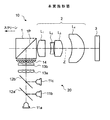
図15は、本発明の実施形態に係る投写型表示装置を説明するための概略図である。
この装置は、3色LED光源11a〜c、該光源11a〜cから出射された各照明光を合成するダイクロイックミラー12a、b、光量均一化手段としてのフライアイインテグレータ13a、b、および振動面が直交する2つの直線偏光の一方を他方に揃えて出射する偏光変換素子(櫛型フィルタ)14よりなる照明光学系20と、偏光分離手段としての偏光分離プリズム(PBS:以下同じ)1、複数枚のレンズ(L1〜L4)よりなる投写レンズ2、および反射型液晶表示素子(LCOS:以下同じ)3よりなる投写光学系10と、を備えてなる。
FIG. 15 is a schematic diagram for explaining a projection display apparatus according to an embodiment of the present invention.
This device includes three-color
すなわち照明光学系20は、R、G、Bの3色を合成してなる所定の直線偏光を出力する従来より知られている照明光学系であり、この所定の直線偏光の偏光方向が、PBS1の偏光分離面1Pにおいて、略100%反射されるように設定されている。
That is, the illumination
また、投写光学系10は、前述したようにPBS1、投写レンズ2およびLCOS3という特徴的な配置とされている。すなわち、照明光学系20からの照明光は、PBS1で反射され、投写レンズ2を、その全長に亘り通過してLCOS3に照射される一方、LCOS3により変調されるとともに逆位相の直線偏光に変換される(直線偏光の位相が180度回転される)。変調光は、直線偏光の位相が逆位相に変換されているので、このLCOS3から反射出射され、投写レンズ2を、その全長に亘って通過した後、PBS1の偏光分離面1Pを透過することになり、図示されないスクリーン上に投写される。なお、LCOS3における照明光の変調は入力された所定の画像信号に基づいてなされるものであり、これにより変調光に担持された画像情報がスクリーン上に拡大投写されることになる。
Further, the projection
このように、本実施形態に係る投写光学系では、照明光は、まずPBS1に入射し、次に投写レンズ2を通過してLCOS3に照射される。その一方、変調光は、LCOS3から反射出射され、投写レンズ2を通過し、PBS1において、照明光の光路と分離されて、スクリーン方向に進む。したがって、本実施形態の投写光学系においては、PBS1が全ての投写レンズ2の拡大側(スクリーン側)に位置することになり、投写レンズ2とLCOS3の距離を短縮することができる。この距離を短縮することができれば、投写レンズ2の縮小側バックをテレセントリックとしつつ、投写レンズ2のうち縮小側のレンズL4の径を小さくすることができる。これにより、投写光学系およびこれを搭載した投写型表示装置のコンパクト化を図ることができる。
As described above, in the projection optical system according to the present embodiment, the illumination light first enters the
また、上記投写光学系10は、下記条件式(1)を満足することが好ましい。
−1.0<FF/f<1.0・・・・(1)
ただし、
FF:投写レンズ2の拡大側焦点位置(投写レンズ2の最も拡大側のレンズL1の拡大側面頂点を原点とし、縮小側に向かう方向を正にとる)
f :投写レンズ2の焦点距離
The projection
-1.0 <FF / f <1.0 (1)
However,
FF: magnification side focal position of the projection lens 2 (the most enlarged side apex of the enlargement side lens L 1 of the
f: Focal length of the
すなわち、上記条件式(1)を満足することにより、投写レンズ2の拡大側瞳位置を、投写レンズ2のうち最も拡大側のレンズL1および、このレンズL1からPBS1にかけての領域付近に設定し易くなるので、投写レンズ2の最も縮小側のレンズL4の径を小さくしつつ、PBS1における偏光分離特性を良好なものとすることができる。このことを、より具体的に説明するならば、PBS1の近傍に、縮小側がテレセントリックな投写レンズの拡大側焦点位置を配置することで、反射型ライトバルブの各画素への照明光や反射型ライトバルブの各画素からの投写光がPBS内で略平行光束となるため、一定の角度内での分離特性が均一化された偏光分離特性を維持することができる、ということである。
That setting, by satisfying the conditional expressions (1), the magnification side pupil position of the
そして、このことにより、画面内の輝度むらや色むらの発生を抑制することができる。
また、PBS1の近傍に、縮小側がテレセントリックな投写レンズの拡大側焦点位置を配置することにより、光束が最も集まり、有効光束領域が小さくなる部分に、コスト的にも重量的にも大きなウエイトを占めるPBSを配置することができ、このPBSを小サイズのものとし得るので、コスト軽減や軽量化を図ることができる。
As a result, it is possible to suppress the occurrence of luminance unevenness and color unevenness in the screen.
Further, by placing the enlargement side focal position of the projection lens on the reduction side in the vicinity of the
この条件式の範囲を外れると、投写レンズの縮小側に近いレンズの径が大型化するとともに、PBS1における偏光分離特性が劣化する。
Outside the range of this conditional expression, the diameter of the lens close to the reduction side of the projection lens increases, and the polarization separation characteristics in the
このような観点から、上記条件式(1)に替えて、下記条件式(1´)を満足することが好ましい。
−0.5<FF/f<0.6・・・・(1´)
From such a viewpoint, it is preferable to satisfy the following conditional expression (1 ′) instead of the conditional expression (1).
-0.5 <FF / f <0.6 (1 ')
さらに、上記条件式(1´)に替えて、下記条件式(1´´)を満足することがより好ましい。
−0.25<FF/f<0.45・・・・(1´´)
Furthermore, it is more preferable to satisfy the following conditional expression (1 ″) instead of the conditional expression (1 ′).
−0.25 <FF / f <0.45 (1 ″)
また、上記投写光学系10において、LCOS3が1枚(単板)で構成され、さらに下記条件式(2)を満足することが好ましい。
Bf/f<0.8・・・・(2)
ただし、
Bf:投写レンズ2の縮小側バックフォーカス
In the projection
Bf / f <0.8 (2)
However,
Bf: Reduction-side back focus of the
LCOS3が単板であれば、投写レンズ2とLCOS3との間に色合成光学系を挿入する必要がなく、この条件式(2)の範囲とすることが容易となり、また実際にこの範囲を満足することにより投写光学系のコンパクト化を図ることができる。
If the
さらに、このような観点から、また光学系の組立て作業性等をも併せて考慮すると、上記条件式(2)に替えて、下記条件式(2´)を満足することがより好ましい。
0.05<Bf/f<0.50・・・・(2´)
Furthermore, from this point of view and considering the assembly workability of the optical system, it is more preferable to satisfy the following conditional expression (2 ′) instead of the conditional expression (2).
0.05 <Bf / f <0.50 (2 ')
また、投写レンズ2の構成枚数としては、携帯性に優れたハンディータイプのプロジェクタとする場合には、レンズ枚数を制限することによるコンパクト化が必須となることから、4枚以下であることが望ましい。すなわち、実用上、4枚(実施例1を参照)、3枚(実施例2、3、4、5を参照)または2枚(実施例6、7を参照)とすることが好ましい。
Further, the number of components of the
また、投写レンズ2の最も縮小側に配置されたレンズの少なくとも1面(図15ではレンズL4の両面)が非球面とされていることが好ましい。これにより、投写光学系において特に重要となる歪曲の収差補正を良好なものとすることができる。また、少ない枚数のレンズにより諸収差をなるべく良好にする、という観点から、他のレンズのうち少なくとも1枚を非球面レンズとすることが好ましい。 Further, it is preferable that at least one surface of a lens disposed closest to the reduction side of the projection lens 2 (both surfaces in Figure 15, the lens L 4) is aspherical. Thereby, the aberration correction of distortion, which is particularly important in the projection optical system, can be improved. Further, from the viewpoint of making various aberrations as good as possible with a small number of lenses, it is preferable that at least one of the other lenses is an aspherical lens.
また、投写レンズ2を構成する全レンズ(図15では、L1〜L4)を通過する光束のうち、光軸Zに対して垂直方向の有効光束径の最大値が15mm以下であることが好ましい。
Moreover, the maximum value of the effective light beam diameter in the direction perpendicular to the optical axis Z among the light beams passing through all the lenses (L 1 to L 4 in FIG. 15) constituting the
すなわち、本実施形態においては、このように有効光束径の最大値が15mm以下となるような、例えば、100ルーメン(好ましくは10ルーメン)程度の明るさ(一般的なプロジェクタの明るさに比して(1/10)〜(1/100)の明るさ)が確保できるような小型のプロジェクタに使用されることが好ましい。 That is, in this embodiment, the brightness (for example, about 100 lumens (preferably 10 lumens) such that the maximum value of the effective light beam diameter is 15 mm or less is compared with the brightness of a general projector. (1/10) to (1/100) brightness) is preferably used for a small projector.
上述したように、本実施形態のものでは、PBS1を投写レンズ2の拡大側(スクリーン側)に配置したことによって多くの利点が得られる反面、光束が投写レンズ2を2回通過することになり、投写レンズの熱的歪が生じ易くなるという課題も発生する。しかしながら、本実施形態の主要用途は前述したように、携帯性に優れたハンディータイプの小型プロジェクタを近距離投影するものであるため、そのような用途には、例えば、100ルーメンの明るさが確保できれば十分と考えられ、そうであれば投写レンズ2を光束が往復しても、熱的歪がほとんど生じない、との本願発明者の知見に基づいてなされたものである。したがって、本発明の投写型光学装置は、このような小型プロジェクタに適用すると極めて有効である。
As described above, in the present embodiment, many advantages can be obtained by arranging the
以下、本発明に係る投写レンズの具体的な実施例について説明する。なお、各実施例において、互いに同様の作用効果をなす部材については同一の符号を付している。 Specific examples of the projection lens according to the present invention will be described below. In addition, in each Example, the same code | symbol is attached | subjected about the member which makes mutually the same effect.
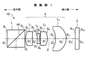
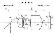
<4枚構成態様>
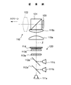
図1に示すように、実施例1に係る投写光学系は、拡大側から順に、PBS1と、両凸レンズよりなる第1レンズL1と、両凹レンズよりなる第2レンズL2と、両凸レンズよりなる第3レンズL3と、光軸Z上で縮小側に凸面を向けた正メニスカス形状の両面非球面レンズよりなる第4レンズL4と、LCOS3と、からなる。なお、上記4枚のレンズL1〜L4により投写レンズ2が構成される。
<Four-sheet configuration>
As shown in FIG. 1, the projection optical system according to Example 1, in order from the magnification side, a PBS1, the first lens L 1 made of a biconvex lens, a second lens L 2 of a biconcave lens, a biconvex lens a third lens L 3, which is a fourth lens L 4, which is a double-sided aspherical lens having a positive meniscus shape with a convex surface on the reduction side on the optical axis Z, and LCOS3, consists. The
本実施例のものでは、上記のように構成されているので、コンパクトでありながらより高性能な光学系とすることができる。 In the present embodiment, since it is configured as described above, it is possible to provide a compact and higher performance optical system.
また、上記第4レンズL4の両面の非球面形状は、下記非球面式により規定される。 Further, the aspheric shape of both surfaces of the fourth lens L 4 is defined by the following aspheric expression.
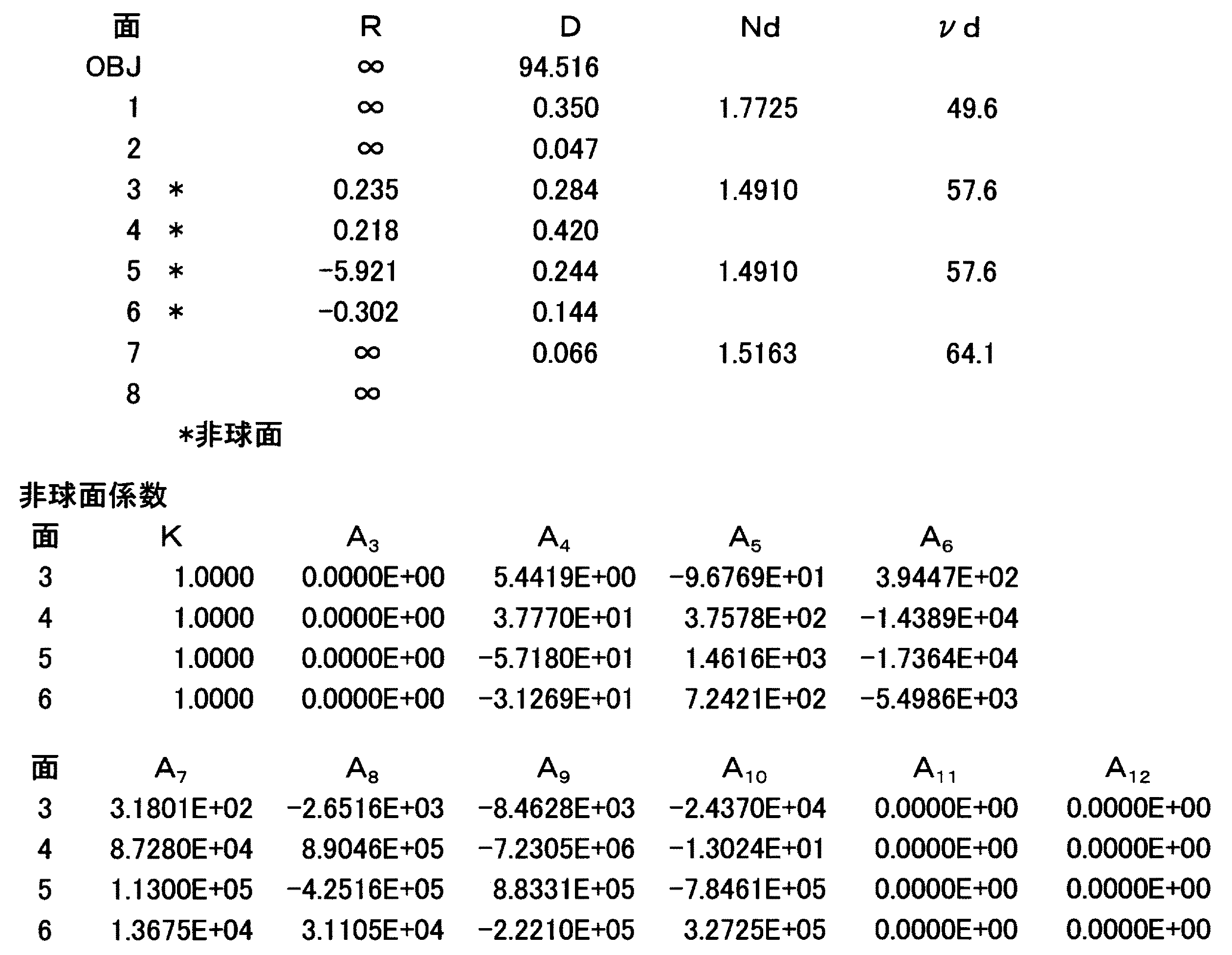
実施例1に係る投写光学系の各レンズ面の曲率半径R、各レンズの中心厚および各レンズ間の空気間隔(以下「軸上面間隔」と称す)D、各レンズのd線における屈折率Ndおよびアッベ数νdの値を、表1の上段に示す。なお、表1および以下の表において面番号の数字は拡大側からの順番を表すものであり、面番号の右側に*印が付された面は非球面とされている。なお、表1の面番号1、2はPBS1の両面を表す。また、表1の下段には各非球面を表す非球面係数を示す。さらに、表1中でOBJとは、図示されないスクリーンの位置を示すものである(以下の表2〜7において同じ)。また、表1中で、第1、2面は、PBS1の両面を示すものである(以下の表2〜4、6、7において同じ)。
The radius of curvature R of each lens surface of the projection optical system according to Example 1, the center thickness of each lens, the air space between the lenses (hereinafter referred to as “axial surface space”) D, and the refractive index N of each lens at the d-line. The values of d and Abbe number ν d are shown in the upper part of Table 1. In Table 1 and the following table, the surface number numbers indicate the order from the enlargement side, and the surface marked with * on the right side of the surface number is an aspheric surface. The
また、実施例1に係る投写光学系は、表8に示すように、条件式(1)、(2)、(1´)、(1´´)(2´)を満足している。 In addition, as shown in Table 8, the projection optical system according to Example 1 satisfies the conditional expressions (1), (2), (1 ′), (1 ″) (2 ′).
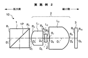
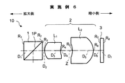
<3枚構成態様の1>
実施例2に係る投写光学系の構成は、図2に示すとおりであり、拡大側から順に、PBS1と、拡大側に凸面を向けた正メニスカスレンズよりなる第1レンズL1と、両凹レンズよりなる第2レンズL2と、光軸Z上で縮小側に凸面を向けた正メニスカス形状の両面非球面レンズよりなる第3レンズL3と、LCOS3と、からなる。なお、上記3枚のレンズL1〜L3により投写レンズ2が構成される(以下の実施例3〜5において同じ)。
<1 of the three-sheet configuration>
Configuration of the projection optical system according to Example 2 is as shown in FIG. 2, in order from the magnification side, a PBS1, the first lens L 1 of a positive meniscus lens having a convex surface facing the magnification side, a biconcave lens a second lens L 2 formed of, a third lens L 3 made of a double-sided aspherical lens having a positive meniscus shape with a convex surface on the reduction side on the optical axis Z, and LCOS3, consists. The three lenses L 1 to L 3 constitute a projection lens 2 (the same applies to Examples 3 to 5 below).
本実施例のものでは、上記のように構成されているので、コンパクト化と高性能化の両者を達成した光学系とすることができる。 In the present embodiment, since it is configured as described above, an optical system that achieves both compactness and high performance can be obtained.
上記第3レンズL3の両面の非球面形状は、上記非球面式により規定される。 Aspherical shape of the both surfaces of the third lens L 3 is defined by the above-mentioned aspheric surface expression.
実施例2に係る投写光学系の各レンズ面の曲率半径R、軸上面間隔D、各レンズのd線における屈折率Ndおよびアッベ数νdの値を、表2の上段に示す。また、各非球面を表す非球面係数を、表2の下段に示す。 The values of the curvature radius R of each lens surface, the axial top surface distance D, the refractive index N d of each lens at the d-line and the Abbe number ν d of the projection optical system according to Example 2 are shown in the upper part of Table 2. In addition, the lower part of Table 2 shows the aspheric coefficients representing the respective aspheric surfaces.
また、実施例2に係る投写光学系は、表8に示すように、条件式(1)、(2)、(1´)、(1´´)(2´)を満足している。 In addition, as shown in Table 8, the projection optical system according to Example 2 satisfies the conditional expressions (1), (2), (1 ′), (1 ″) (2 ′).
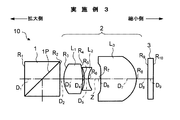
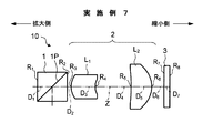
<3枚構成態様の2>
実施例3に係る投写光学系の構成は、図3に示すとおりであり、実施例2のものと略同様の構成とされているが、主として、第1レンズL1が両凸レンズとされている点、および第2レンズL2が両凹形状の両面非球面レンズとされている点、および第3レンズL3が光軸Z上において両凸形状の両面非球面レンズとされている点、において相違する。
<2 of the three-sheet configuration mode>
Configuration of the projection optical system according to Example 3 is as shown in FIG. 3, but has a substantially same structure as that of Example 2, mainly, the first lens L 1 is a biconvex lens points, and that the second lens L 2 is a biconcave double-sided aspheric lens, and the third lens L 3 is that it is a bi-aspherical biconvex lens on the optical axis Z, in Is different.
本実施例のものでは、上記のように構成されているので、コンパクト化と高性能化の両者を達成した光学系とすることができる。 In the present embodiment, since it is configured as described above, an optical system that achieves both compactness and high performance can be obtained.
上記第2レンズL2および第3レンズL3の両面の非球面形状は、上記非球面式により規定される。 Both surfaces aspheric shape of the second lens L 2 and third lens L 3 is defined by the above-mentioned aspheric surface expression.
実施例3に係る投写光学系の各レンズ面の曲率半径R、軸上面間隔D、各レンズのd線における屈折率Ndおよびアッベ数νdの値を、表3の上段に示す。また、各非球面を表す非球面係数を、表3の下段に示す。 The values of the curvature radius R of each lens surface, the axial top surface distance D, the refractive index N d of each lens at the d-line and the Abbe number ν d of the projection optical system according to Example 3 are shown in the upper part of Table 3. In addition, the lower part of Table 3 shows the aspheric coefficients representing the respective aspheric surfaces.
実施例3に係る投写光学系は、表8に示すように、上記条件式(1)、(2)、(1´)、(1´´)(2´)を満足するように構成されている。 As shown in Table 8, the projection optical system according to Example 3 is configured to satisfy the conditional expressions (1), (2), (1 ′), (1 ″) and (2 ′). Yes.
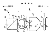
<3枚構成態様の3>
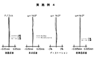
実施例4に係る投写光学系の構成は、図4に示すとおりであり、実施例3のものと略同様の構成とされている。
<Three-
The configuration of the projection optical system according to Example 4 is as shown in FIG. 4 and is substantially the same as that of Example 3.
本実施例のものでは、このように構成されているので、コンパクト化と高性能化の両者を達成した光学系とすることができる。 In the present embodiment, since it is configured in this way, an optical system that achieves both compactness and high performance can be obtained.
上記第2レンズL2および第3レンズL3の両面の非球面形状は、上記非球面式により規定される。 Both surfaces aspheric shape of the second lens L 2 and third lens L 3 is defined by the above-mentioned aspheric surface expression.
実施例4に係る投写光学系の各レンズ面の曲率半径R、軸上面間隔D、各レンズのd線における屈折率Ndおよびアッベ数νdの値を、表4の上段に示す。また、各非球面を表す非球面係数を、表4の下段に示す。 The values of the curvature radius R of each lens surface, the axial top surface distance D, the refractive index N d of each lens at the d-line and the Abbe number ν d of the projection optical system according to Example 4 are shown in the upper part of Table 4. In addition, the lower part of Table 4 shows the aspheric coefficients representing the respective aspheric surfaces.
実施例4に係る投写光学系は、表8に示すように、上記条件式(1)、(2)、(1´)、(1´´)(2´)を満足するように構成されている。 As shown in Table 8, the projection optical system according to Example 4 is configured to satisfy the conditional expressions (1), (2), (1 ′), (1 ″) and (2 ′). Yes.
<3枚構成態様の4>
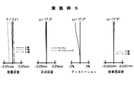
実施例5に係る投写光学系の構成は、図5に示すとおりであり、実施例3、4のものと略同様の構成とされているが、主として、偏光分離手段として偏光分離ミラー1Aが用いられている点、第2レンズL2が球面レンズよりなる点、および第3レンズL3が光軸Z上のみならず、レンズ全体としても両凸形状の両面非球面レンズとされている点において相違する。
<4 of the three-sheet configuration mode>
The configuration of the projection optical system according to Embodiment 5 is as shown in FIG. 5 and is substantially the same as that of
本実施例のものでは、上記のように構成されているので、コンパクト化と高性能化の両者を達成した光学系とすることができる。 In the present embodiment, since it is configured as described above, an optical system that achieves both compactness and high performance can be obtained.
上記第3レンズL3の両面の非球面形状は、上記非球面式により規定される。 Aspherical shape of the both surfaces of the third lens L 3 is defined by the above-mentioned aspheric surface expression.
実施例5に係る投写光学系の各レンズ面の曲率半径R、軸上面間隔D、各レンズのd線における屈折率Ndおよびアッベ数νdの値を、表5の上段に示す。なお、表5の面番号1、2は第1レンズL1の両面を表すものである。
また、各非球面を表す非球面係数を、表5の下段に示す。
The values of the curvature radius R of each lens surface, the axial top surface distance D, the refractive index N d of each lens at the d-line and the Abbe number ν d of the projection optical system according to Example 5 are shown in the upper part of Table 5. The
In addition, the lower part of Table 5 shows the aspheric coefficients representing the respective aspheric surfaces.
実施例5に係る投写光学系は、表8に示すように、上記条件式(1)、(2)、(1´)、(1´´)(2´)を満足するように構成されている。 As shown in Table 8, the projection optical system according to Example 5 is configured to satisfy the conditional expressions (1), (2), (1 ′), (1 ″) and (2 ′). Yes.
<2枚構成態様の1>
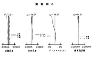
実施例6に係る投写光学系の構成は、図6に示すとおりであり、拡大側から順に、PBS1と、全体として、拡大側に凸面を向けたメニスカス形状の両面非球面レンズよりなる第1レンズL1と、全体として、縮小側に凸面を向けた正メニスカス形状の両面非球面レンズよりなる第2レンズL2と、LCOS3と、からなる。なお、上記2枚のレンズL1、L2により投写レンズ2が構成される(以下の実施例7において同じ)。
<1 of two-sheet configuration>
The configuration of the projection optical system according to Example 6 is as shown in FIG. 6. In order from the magnification side, the first lens is composed of
本実施例のものでは、上記のように構成されているので、よりコンパクトな光学系とすることができる。 In the present embodiment, since it is configured as described above, a more compact optical system can be obtained.
上記第1レンズL1および上記第2レンズL2の両面の非球面形状は、上記非球面式により規定される。 Both surfaces aspheric shape of the first lens L 1 and the second lens L 2 is defined by the above-mentioned aspheric surface expression.
実施例6に係る投写光学系の各レンズ面の曲率半径R、軸上面間隔D、各レンズのd線における屈折率Ndおよびアッベ数νdの値を、表6の上段に示す。また、各非球面を表す非球面係数を、表6の下段に示す。 Table 6 shows the values of the radius of curvature R of each lens surface, the axial top surface distance D, the refractive index N d of each lens at the d-line, and the Abbe number ν d in the projection optical system according to Example 6. In addition, the lower part of Table 6 shows the aspheric coefficients representing the respective aspheric surfaces.
また、実施例6に係る投写光学系は、表8に示すように、条件式(1)、(2)、(1´)、(1´´)(2´)を満足している。 In addition, as shown in Table 8, the projection optical system according to Example 6 satisfies the conditional expressions (1), (2), (1 ′), (1 ″) (2 ′).
<2枚構成態様の2>
実施例7に係る投写光学系の構成は、図7に示すとおりであり、実施例6のものと略同様の構成とされている。
<2 of 2 sheets configuration mode>
The configuration of the projection optical system according to Example 7 is as shown in FIG. 7, and is substantially the same as that of Example 6.
本実施例のものでは、このように構成されているので、よりコンパクトな光学系とすることができる。 In the present embodiment, since it is configured as described above, a more compact optical system can be obtained.
上記第1レンズL1および上記第2レンズL2の両面の非球面形状は、上記非球面式により規定される。 Both surfaces aspheric shape of the first lens L 1 and the second lens L 2 is defined by the above-mentioned aspheric surface expression.
実施例7に係る投写光学系の各レンズ面の曲率半径R、軸上面間隔D、各レンズのd線における屈折率Ndおよびアッベ数νdの値を、表7の上段に示す。また、各非球面を表す非球面係数を、表7の下段に示す。 Table 7 shows the values of the curvature radius R of each lens surface, the axial top surface distance D, the refractive index N d of each lens at the d-line, and the Abbe number ν d of the projection optical system according to Example 7. In addition, the lower part of Table 7 shows the aspheric coefficients representing the respective aspheric surfaces.
また、実施例7に係る投写光学系は、表8に示すように、条件式(1)、(2)、(1´)、(1´´)(2´)を満足している。 In addition, as shown in Table 8, the projection optical system according to Example 7 satisfies the conditional expressions (1), (2), (1 ′), (1 ″) (2 ′).
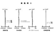
また、図8〜14は、実施例1〜7に係る投写光学系の諸収差(球面収差、非点収差、ディストーションおよび倍率色収差)を示す収差図である。これらの収差図において、ωは半画角を示し、球面収差の収差図にはd線、F線およびC線の収差曲線を示し、倍率色収差の収差図にはd線に対するF線(点線:以下同じ)およびC線(2点鎖線:以下同じ)の収差曲線を示している。図8〜14に示すように、実施例1〜7に係る投写光学系は、歪曲収差や倍率色収差をはじめ各収差が良好に補正されている。 FIGS. 8 to 14 are aberration diagrams showing various aberrations (spherical aberration, astigmatism, distortion and lateral chromatic aberration) of the projection optical system according to Examples 1 to 7. FIGS. In these aberration diagrams, ω represents a half angle of view, the aberration diagram of spherical aberration shows aberration curves of d-line, F-line, and C-line, and the aberration diagram of lateral chromatic aberration shows F-line (dotted line: Aberration curves of C-line (two-dot chain line: same below) are shown. As shown in FIGS. 8 to 14, in the projection optical systems according to Examples 1 to 7, each aberration including distortion and lateral chromatic aberration is well corrected.
なお、本発明の投写光学系としては、上記実施例のものに限られるものではなく種々の態様の変更が可能であり、例えば各レンズの曲率半径Rおよびレンズ間隔(もしくはレンズ厚)Dを適宜変更することが可能である。 The projection optical system of the present invention is not limited to the above-described embodiment, and various modifications can be made. For example, the radius of curvature R and the lens interval (or lens thickness) D of each lens are appropriately set. It is possible to change.
また、本発明の投写型表示装置としても、上記構成のものに限られるものではなく、本発明の投写光学系を備えた種々の装置構成が可能である。ライトバルブとしては、反射タイプのものであればよく、例えば、上記反射型液晶表示素子(LCOS)に替えて、傾きを変えることができる微小な鏡が略平面上に多数形成された微小ミラー素子(例えば、テキサス・インスツルメント社製のデジタルマイクロミラーデバイス)を用いることができる。また、照明光学系としても、ライトバルブの種類に対応した適切な構成を採用することができる。 Further, the projection display device of the present invention is not limited to the above-described configuration, and various device configurations including the projection optical system of the present invention are possible. The light valve only needs to be of a reflective type. For example, instead of the reflective liquid crystal display element (LCOS), a micro mirror element in which a large number of micro mirrors capable of changing the tilt are formed on a substantially flat surface. (For example, a digital micromirror device manufactured by Texas Instruments) can be used. Also, as the illumination optical system, an appropriate configuration corresponding to the type of light valve can be adopted.
また、上述した偏光分離面と反射型液晶表示素子との間の光路中にミラー等が配設されている場合にも、上記実施形態のものと実質的に同じ作用を奏するのであれば、上記実施形態に含まれるものである。 In addition, when a mirror or the like is disposed in the optical path between the polarization separation surface and the reflective liquid crystal display element, the above-described embodiment can be used as long as the same effect is obtained as in the above embodiment. It is included in the embodiment.
また、上記実施形態においては、偏光分離手段において、照明光を反射する一方変調光を透過して、両者の光路を分離するようにしているが、照明光を透過する一方変調光を反射するようにして両者の光路を分離してもよい。 In the above embodiment, the polarized light separating means transmits the one modulated light that reflects the illumination light and separates the optical paths of the both, but the one that transmits the illumination light and reflects the modulated light. Thus, the optical paths of both may be separated.
また、投写レンズを構成するレンズの枚数は4枚以下とすることが好ましいが、レンズ枚数を5枚以上としたものに、本発明を適用することは勿論可能である。 The number of lenses constituting the projection lens is preferably 4 or less, but the present invention can naturally be applied to a case where the number of lenses is 5 or more.
また、前記光源部の発光体としては、半導体レーザーなどの他の発光体を用いることが可能であり、これにより装置のコンパクト化を図ることができる。勿論、他の種類のレーザーや他の種類の光源を用いることも可能である。 Further, as the light emitter of the light source unit, other light emitters such as a semiconductor laser can be used, thereby making the apparatus compact. Of course, other types of lasers and other types of light sources can be used.
なお、照明光は、光源から出射される段階で直線偏光であってもよいし、図15に示すように、光源から出射された後に直線偏光に変換されるようにしてもよい。 The illumination light may be linearly polarized light when it is emitted from the light source, or may be converted to linearly polarized light after being emitted from the light source as shown in FIG.
1、101 偏光分離プリズム(PBS)
1A 偏光分離ミラー
2、102 投写レンズ
3、103 反射型液晶表示素子(LCOS)
10、110 投写光学系
11a〜11c、111a〜111c 3色LED光源
12a、12b、112a、112b ダイクロイックミラー
13a、13b、113a、113b フライアイインテグレータ
14、114 偏光変換素子(櫛型フィルタ)
20、120 照明光学系
L1〜L4 レンズ
R1〜R10 レンズ面等の曲率半径
D1〜D9 軸上面間隔
Z 光軸
1, 101 Polarization separation prism (PBS)
DESCRIPTION OF
10, 110 Projection
20,120 illumination optical system L 1 ~L 4 lens R 1 to R of curvature such as 10 lens surface radius D 1 to D 9 axial distance Z optical axis
Claims (7)
該反射型ライトバルブに入射する前記照明光、および該反射型ライトバルブから出射された変調光を通過させる、縮小側がテレセントリックとされた投写レンズと、
該投写レンズに入射する前記照明光と、該投写レンズから出射された変調光の光路を分離する偏光分離手段と、
をこの順に配列してなることを特徴とする投写光学系。 A reflection type light valve that reflects and emits modulated light obtained by modulating incident illumination light according to an input image signal;
A projection lens that is telecentric on the reduction side and transmits the illumination light incident on the reflective light valve and the modulated light emitted from the reflective light valve;
Polarized light separating means for separating the illumination light incident on the projection lens and the optical path of the modulated light emitted from the projection lens;
Are arranged in this order, and a projection optical system.
−1.0<FF/f<1.0・・・・(1)
ただし、
FF:前記投写レンズの拡大側焦点位置(当該投写レンズの最も拡大側のレンズの拡大側面頂点を原点とし、縮小側に向かう方向を正にとる)
f :前記投写レンズの焦点距離 The projection optical system according to claim 1, wherein the projection lens satisfies the following conditional expression (1).
-1.0 <FF / f <1.0 (1)
However,
FF: Magnification side focal position of the projection lens (the magnifying side vertex of the most magnifying side lens of the projection lens is the origin, and the direction toward the reduction side is positive)
f: Focal length of the projection lens
Bf/f<0.8・・・・(2)
ただし、
Bf:前記投写レンズの縮小側バックフォーカス 3. The projection optical system according to claim 1, wherein the reflection type light valve is composed of a single sheet and further satisfies the following conditional expression (2).
Bf / f <0.8 (2)
However,
Bf: Reduction focal point of the projection lens
前記照明光を発光するとともに、該照明光の光量均一化を図る照明光学系とを備えたことを特徴とする投写型表示装置。
A projection optical system according to any one of claims 1 to 6;
A projection display device comprising: an illumination optical system that emits the illumination light and makes the amount of illumination light uniform.
Priority Applications (4)
| Application Number | Priority Date | Filing Date | Title |
|---|---|---|---|
| JP2009143689A JP5259503B2 (en) | 2009-06-16 | 2009-06-16 | Projection optical system and projection display device using the same |
| TW099208839U TWM391104U (en) | 2009-06-16 | 2010-05-12 | Optical projection system and projection-type display device using the same |
| CN2010202249251U CN201837783U (en) | 2009-06-16 | 2010-06-08 | Projection optical system and projection type displayer using same |
| US12/797,089 US8303117B2 (en) | 2009-06-16 | 2010-06-09 | Projection optical system and projection-type display apparatus using the same |
Applications Claiming Priority (1)
| Application Number | Priority Date | Filing Date | Title |
|---|---|---|---|
| JP2009143689A JP5259503B2 (en) | 2009-06-16 | 2009-06-16 | Projection optical system and projection display device using the same |
Publications (2)
| Publication Number | Publication Date |
|---|---|
| JP2011002518A JP2011002518A (en) | 2011-01-06 |
| JP5259503B2 true JP5259503B2 (en) | 2013-08-07 |
Family
ID=43306160
Family Applications (1)
| Application Number | Title | Priority Date | Filing Date |
|---|---|---|---|
| JP2009143689A Active JP5259503B2 (en) | 2009-06-16 | 2009-06-16 | Projection optical system and projection display device using the same |
Country Status (4)
| Country | Link |
|---|---|
| US (1) | US8303117B2 (en) |
| JP (1) | JP5259503B2 (en) |
| CN (1) | CN201837783U (en) |
| TW (1) | TWM391104U (en) |
Families Citing this family (7)
| Publication number | Priority date | Publication date | Assignee | Title |
|---|---|---|---|---|
| WO2012144168A1 (en) * | 2011-04-19 | 2012-10-26 | 富士フイルム株式会社 | Projection lens and projection-type display device using same |
| JP6361333B2 (en) | 2013-07-31 | 2018-07-25 | 日亜化学工業株式会社 | Light source device and optical engine |
| JP6268889B2 (en) * | 2013-10-04 | 2018-01-31 | セイコーエプソン株式会社 | Lighting device |
| JP6762789B2 (en) * | 2016-07-20 | 2020-09-30 | 天津欧菲光電有限公司Tianjin Ofilm Opto Electronics Co., Ltd | Imaging lens and imaging device |
| CN107831630B (en) * | 2017-12-15 | 2023-12-29 | 浙江舜宇光学有限公司 | projection lens |
| WO2019114232A1 (en) * | 2017-12-15 | 2019-06-20 | 浙江舜宇光学有限公司 | Projection lens |
| TWI742822B (en) * | 2020-08-27 | 2021-10-11 | 新鉅科技股份有限公司 | Four-piece infrared projection lens system |
Family Cites Families (12)
| Publication number | Priority date | Publication date | Assignee | Title |
|---|---|---|---|---|
| JP2887004B2 (en) * | 1991-04-26 | 1999-04-26 | キヤノン株式会社 | Projection optical system and optical apparatus having the same |
| JPH05203872A (en) * | 1992-01-24 | 1993-08-13 | Canon Inc | Projection optics |
| US5597222A (en) * | 1995-01-17 | 1997-01-28 | Ibm Corporation | Optical relay lens system for projection displays |
| US6497485B1 (en) * | 2000-01-20 | 2002-12-24 | Seiko Epson Corporation | Image projection system having uniform brightness |
| US6185041B1 (en) * | 1998-10-23 | 2001-02-06 | Duke University | Projection lens and system |
| US6172813B1 (en) * | 1998-10-23 | 2001-01-09 | Duke University | Projection lens and system including a reflecting linear polarizer |
| US6239917B1 (en) * | 1998-10-23 | 2001-05-29 | Duke University | Thermalization using optical components in a lens system |
| US6839181B1 (en) * | 2003-06-25 | 2005-01-04 | Eastman Kodak Company | Display apparatus |
| JP2010079252A (en) * | 2008-09-01 | 2010-04-08 | Fujinon Corp | Small projection lens and projection display using the same |
| JP5442515B2 (en) * | 2010-03-30 | 2014-03-12 | 富士フイルム株式会社 | Projection lens and projection display device using the same |
| TW201137497A (en) * | 2010-04-30 | 2011-11-01 | E Pin Optical Industry Co Ltd | Four-piece projection lens system and the projection apparatus using the same |
| US20120002171A1 (en) * | 2010-06-30 | 2012-01-05 | Shin-Gwo Shiue | Projection lens module of pico projector |
-
2009
- 2009-06-16 JP JP2009143689A patent/JP5259503B2/en active Active
-
2010
- 2010-05-12 TW TW099208839U patent/TWM391104U/en not_active IP Right Cessation
- 2010-06-08 CN CN2010202249251U patent/CN201837783U/en not_active Expired - Lifetime
- 2010-06-09 US US12/797,089 patent/US8303117B2/en active Active
Also Published As
| Publication number | Publication date |
|---|---|
| US8303117B2 (en) | 2012-11-06 |
| CN201837783U (en) | 2011-05-18 |
| US20100315598A1 (en) | 2010-12-16 |
| TWM391104U (en) | 2010-10-21 |
| JP2011002518A (en) | 2011-01-06 |
Similar Documents
| Publication | Publication Date | Title |
|---|---|---|
| JP6517294B2 (en) | Projection optical system | |
| JP5670602B2 (en) | Projection lens and projection display device | |
| JP5468966B2 (en) | Projection lens and projection display device using the same | |
| JP5042708B2 (en) | Projection lens and projection display device using the same | |
| JP5431077B2 (en) | Projection lens and projection display device | |
| JP5795363B2 (en) | Projection lens and projection display device using the same | |
| JP5259503B2 (en) | Projection optical system and projection display device using the same | |
| JP2010079252A (en) | Small projection lens and projection display using the same | |
| JP2009251457A (en) | Projection optical system and projection type display using the same | |
| JPWO2012105181A1 (en) | Projection lens and projection display device | |
| JP2011209564A (en) | Projection lens and projection-type display device using the same | |
| JP2011033657A (en) | Wide-angle projection zoom lens and projection display | |
| JP2011085744A (en) | Projection lens for small projector | |
| JP5676748B2 (en) | Projection optical system and projection display device | |
| JP5384415B2 (en) | Wide angle lens for projection and projection display device | |
| JP6072720B2 (en) | Projection lens and projection display device | |
| JP2015184306A (en) | Projection type display device | |
| JP5275902B2 (en) | Wide angle lens for projection and projection display device | |
| JP2009251458A (en) | Projection optical system and projection type display using the same | |
| JP2008309991A (en) | Projection lens and projection display apparatus using the same | |
| JP4756903B2 (en) | Wide-angle lens and zoom lens | |
| JP2012073337A (en) | Projection lens and projection type display apparatus | |
| JP5229955B2 (en) | Projection lens and projection display device using the same | |
| JP2010128318A (en) | Projection optical system and image projection device | |
| JP2010145917A (en) | Image projection apparatus |
Legal Events
| Date | Code | Title | Description |
|---|---|---|---|
| A621 | Written request for application examination |
Free format text: JAPANESE INTERMEDIATE CODE: A621 Effective date: 20120119 |
|
| TRDD | Decision of grant or rejection written | ||
| A01 | Written decision to grant a patent or to grant a registration (utility model) |
Free format text: JAPANESE INTERMEDIATE CODE: A01 Effective date: 20130423 |
|
| A61 | First payment of annual fees (during grant procedure) |
Free format text: JAPANESE INTERMEDIATE CODE: A61 Effective date: 20130424 |
|
| FPAY | Renewal fee payment (event date is renewal date of database) |
Free format text: PAYMENT UNTIL: 20160502 Year of fee payment: 3 |
|
| R150 | Certificate of patent or registration of utility model |
Ref document number: 5259503 Country of ref document: JP Free format text: JAPANESE INTERMEDIATE CODE: R150 Free format text: JAPANESE INTERMEDIATE CODE: R150 |
|
| R250 | Receipt of annual fees |
Free format text: JAPANESE INTERMEDIATE CODE: R250 |
|
| R250 | Receipt of annual fees |
Free format text: JAPANESE INTERMEDIATE CODE: R250 |
|
| R250 | Receipt of annual fees |
Free format text: JAPANESE INTERMEDIATE CODE: R250 |
|
| R250 | Receipt of annual fees |
Free format text: JAPANESE INTERMEDIATE CODE: R250 |
|
| R250 | Receipt of annual fees |
Free format text: JAPANESE INTERMEDIATE CODE: R250 |
|
| R250 | Receipt of annual fees |
Free format text: JAPANESE INTERMEDIATE CODE: R250 |
|
| R250 | Receipt of annual fees |
Free format text: JAPANESE INTERMEDIATE CODE: R250 |
|
| R250 | Receipt of annual fees |
Free format text: JAPANESE INTERMEDIATE CODE: R250 |
|
| R250 | Receipt of annual fees |
Free format text: JAPANESE INTERMEDIATE CODE: R250 |
|
| R250 | Receipt of annual fees |
Free format text: JAPANESE INTERMEDIATE CODE: R250 |
|
| R250 | Receipt of annual fees |
Free format text: JAPANESE INTERMEDIATE CODE: R250 |