JP5259463B2 - High temperature dead end seal - Google Patents
High temperature dead end seal Download PDFInfo
- Publication number
- JP5259463B2 JP5259463B2 JP2009060556A JP2009060556A JP5259463B2 JP 5259463 B2 JP5259463 B2 JP 5259463B2 JP 2009060556 A JP2009060556 A JP 2009060556A JP 2009060556 A JP2009060556 A JP 2009060556A JP 5259463 B2 JP5259463 B2 JP 5259463B2
- Authority
- JP
- Japan
- Prior art keywords
- seal
- ring
- cooling jacket
- hollow cylindrical
- high temperature
- Prior art date
- Legal status (The legal status is an assumption and is not a legal conclusion. Google has not performed a legal analysis and makes no representation as to the accuracy of the status listed.)
- Active
Links
Images


Landscapes
- Mechanical Sealing (AREA)
Description
本発明は、石油精製、石油化学および製鉄化学等において200℃を越えるような高温液、たとえば、石油精製プラントの減圧蒸留設備の熱油を扱う機器のシールに用いられる高温用デッドエンドシールに関する。
デッドエンドとはシール流体が循環しないシール室の意味であり、デッドエンドシールとは、ノーフラッシング、すなわち、スタフィングボックス内にシール流体の注入あるいは排出を行わない、またはエクスターナル流体を注入しない方式のメカニカルシールのことである。
The present invention relates to a high-temperature dead-end seal used for sealing equipment that handles high-temperature liquids exceeding 200 ° C. in petroleum refining, petrochemical, iron-making chemistry, and the like, for example, hot oil in vacuum distillation equipment of petroleum refining plants.
Dead end means a seal chamber in which seal fluid does not circulate, and dead end seal means no flushing, that is, no injection or discharge of seal fluid into the stuffing box, or no injection of external fluid. It is a mechanical seal.
従来、熱媒油、残渣油、ボトム液などの熱油用メカニカルシールには熱負荷を軽減するためにシングルシールの場合にはクーラーによって冷却した自液か温度の低い外部液をフラッシングしていた。しかし、この方式では、省エネの観点からすると、ポンプ内に冷却液が流入し、装置全体として熱効率が低下したり、クーラーの冷却水の消費や外部液の消費などエネルギの大きな損失が発生するという問題があった。
そこで、密封液が200℃を越えるような高温液において、冷却液によるフラッシングを行わないメカニカルシールとして、図5に示すようなメカニカルシール、すなわち、高温用デッドエンドシールが提案されている(以下「従来技術1」という。)。
図5に示される従来技術1の高温用デッドエンドシールは、回転軸50とハウジング51との間に形成した軸封部53に装着されて、回転軸50とハウジング51との間をシールするメカニカルシールであって、ハウジング51側に取り付けられるカラー54と、カラー54に連結されるベローズ55と、ベローズ55に連結されるリテーナ56と、リテーナ56に嵌合されるシール リング57と、回転軸50側に取り付けられるメイティングリング58と、カラー54の内周側に所定の間隔をおいて設けられた筒状のバッフルスリーブ59を備えている。
In the past, mechanical seals for heat oil such as heat transfer oil, residual oil, and bottom liquid have been flushed with either self-cooled or cool external liquid cooled by a cooler in the case of a single seal to reduce the heat load. . However, in this method, from the viewpoint of energy saving, the coolant flows into the pump, the thermal efficiency of the entire device is reduced, and there is a large loss of energy such as the consumption of cooling water from the cooler and the consumption of external liquid. There was a problem.
Therefore, a mechanical seal as shown in FIG. 5, that is, a high-temperature dead end seal has been proposed as a mechanical seal that does not perform flushing with a cooling liquid in a high-temperature liquid in which the sealing liquid exceeds 200 ° C. (hereinafter, “
The high temperature dead end seal of the
そして、ベローズ55の端部に溶接されたリテーナ56にカーボンなどの摺動材料
で作られたシールリング57が密封的に焼嵌めまたは圧入されている。シールリング57端面の摺動トルクは、リテーナ56→ベローズ55→カラー54に伝わり、シールカバー60にボルトで固定されたカラー54が受けている。シールリング57端面の潤滑状況の変化による円周方向の微振動(ヒステリックスリップ)はリテーナ56→ベローズ55に伝搬する。この円周方向の微振動を抑えるために、リテーナ56内周とシールカバー60にボルトで固定されたバッフルスリーブ59がリテーナ56内周部まで伸びており、バッフルスリーブ59の外径とリテーナ最内径とを円周の部分的(多くは4等配)に微小隙間に絞り、振動した際には、この微小隙間以上に振れないように制振作用を持たせている。
A
また、ハウジング51に設けられた冷却ジャケット61により、スタフィングボックス62内を冷却している。さらに、スチームクエンチをバッフルスリーブ59でメカニカルシールの静止側内周とバッフルスリーブ59外周とで形成された隙間を流路として、シール端面部に供給し、メカニカルシール部を冷却するとともに、シール端面からにじみ漏れした液を洗浄し、排出している。
しかしながら、従来技術1のメカニカルシールには、次のような問題があった。
フラッシングによる冷却がないので、メカニカルシール部はハウジング51に設けられた冷却ジャケット61とメカニカルシールの静止側内周とバッフルスリーブ59外周に供給されるスチームクエンチとで冷却するが、冷却効果はハウジング51に設けられた冷却ジャケット61にほとんど依存している。ところが、冷却ジャケット61の設計により、冷却効果にばらつきがあり、冷却効果が不十分であると、メカニカルシール部の温度が十分に下がらず、その結果、例えば、シール液に揮発性留分が含まれていたりする場合のように、摺動発熱により、シール端面間で容易に揮発性留分が沸騰し、シール端面間の潤滑が乏しくなるとともに、不安定になると、シール端面が高サイクルで円周方向に微振動し、摺動トルクも高サイクルで変動し、この微振動がリテーナ56を経由してベローズ55に伝搬し、ベローズ55が高サイクルの振動(ねじり−戻り)をし、疲労破壊して高温流体が機外に流出することがあった。
Further, the inside of the
However, the mechanical seal of
Since there is no cooling due to flushing, the mechanical seal portion is cooled by a
従来技術1と同じく、冷却液によるフラッシングを行わない、高温用デッドエンドシールとして、メイティングリングの後方の回転軸の部分にポンピングリングを取り付けて、該ポンピングリングの外周側を軸封部側に位置させ、内周側を機内側に位置させるとともに、該ポンピングリングに、内周側から外周側に貫通するポンピング孔を複数箇所に設けて、該ポンピング孔を介して機内側と軸封部側とを相互に連通し、かつ、該ポンピング孔の後方のポンピングリングの外周面とハウジングの内周面との間で微小隙間の絞り部を形成したメカニカルシールが知られている(以下「従来技術2」という。たとえば、特許文献1参照)。
As with the
従来技術2のメカニカルシールは、フラッシングを行わないで、軸封部を昇圧させるという手段をとることにより、シールリングとメイティングリングとの摺動面にエアー等が噛み込むことを防止し、摺動面が損傷したり、早期に摩耗したりすることを防止するものである。
この従来技術2においては、シールリングとメイティングリングとの摺動面にエアー等が噛み込むことを防止し、摺動面が損傷したり、早期に摩耗したりすることを防止できるものであるが、例えば、シール液に揮発性留分が含まれていたりする場合のように、摺動発熱により、シール端面間で容易に揮発性留分が沸騰し、シール端面間の潤滑が乏しくなるとともに、不安定になると、シール端面が高サイクルで円周方向に微振動し、摺動トルクも高サイクルで変動し、この微振動がリテーナを経由してベローズに伝搬し、ベローズが高サイクルの振動(ねじり−戻り)をし、疲労破壊して高温流体が機外に流出するという問題を解消できるものではなかった。
The mechanical seal of the
In this
一方、ボイラー給水などの高温流体を取り扱うポンプ等に使用するメカニカルシールの冷却装置に関するものとして、内部に冷却水が循環する冷却室を備えたスタフィングボックスの内方と回転軸との間で相対的に回転してシール液をシールする回転環を有する回転体と固定環とからなるメカニカルシールにおいて、前記冷却室内にクーリングチューブを配設し、該クーリングチューブの両端部を前記スタフィングボックス内面に開口させ、その一方の端部開口もしくはこの開口に近接する前記回転体の外周部の少なくとも一方に環状溝部を設けるとともに、回転体の一部に前記環状溝に向かう多数の貫通孔を設け、前記回転軸の回転にもとづく前記貫通孔のポンプ作用によりシール液をクーリングチューブ内に循環させて冷却されたシール液にて前記密封端面近傍を冷却するようにした発明が知られている(以下「従来技術3」という。たとえば、特許文献2参照。)。
On the other hand, as a cooling device for mechanical seals used for pumps that handle high-temperature fluid such as boiler feed water, the relative relationship between the inside of a stuffing box with a cooling chamber in which cooling water circulates and the rotating shaft In a mechanical seal comprising a rotating body having a rotating ring that rotates and seals sealing liquid and a stationary ring, a cooling tube is disposed in the cooling chamber, and both ends of the cooling tube are disposed on the inner surface of the stuffing box. Providing an annular groove in at least one of the one end opening or the outer peripheral portion of the rotating body adjacent to the opening, and providing a plurality of through holes toward the annular groove in a part of the rotating body, Seal which is cooled by circulating seal liquid in the cooling tube by the pump action of the through hole based on rotation of the rotating shaft Said sealing edge surface vicinity so as to cool invention are known in (hereinafter referred to as "
従来技術3のメカニカルシールは、回転体の外周部に環状溝部を設けるとともに、回転体の一部に環状溝に向かう多数の貫通孔を設け、回転軸の回転にもとづく貫通孔のポンプ作用によりシール液をクーリングチューブ内に循環させて冷却されたシール液にて前記密封端面近傍を冷却する方式であるため、ボイラー給水のようにシール液に不純物が含まれておらず、かつ、粘性が小さい場合には適用できるものであるが、シール液が熱媒油、残渣油、ボトム液などの熱油の場合には、シール液の循環がスムースに行われないため、これらの高温液を扱う機器に適用することができないという問題があった。
The mechanical seal of the
本発明は、石油精製、石油化学および製鉄化学等において200℃を越えるような高温液、たとえば、石油精製プラントの減圧蒸留設備の熱油を扱う機器のシールに用いられる高温用デッドエンドシールにおいて、スタフィングボックス内に冷却ジャケットを設け、スタフィングボックス内の容積を縮小させるとともに、メカニカルシール部外周と冷却ジャケットの内周で絞りを形成することにより、ハウジングに冷却ジャケットがない場合や該ハウジングの冷却ジャケットの冷却効果が少ない場合であっても、フラッシングを行うことなくメカニカルシール部の冷却を効果的に行えるようにし、装置全体としての熱効率を向上させた高温用デッドエンドシールを提供することを目的としている。 The present invention relates to a high-temperature liquid that exceeds 200 ° C. in petroleum refining, petrochemical, steelmaking chemistry, etc., for example, a high-temperature dead end seal used for sealing equipment for handling hot oil in a vacuum distillation facility of an oil refining plant. A cooling jacket is provided in the stuffing box, the volume in the stuffing box is reduced, and a throttle is formed on the outer periphery of the mechanical seal portion and the inner periphery of the cooling jacket, so that the housing has no cooling jacket or the housing Even if the cooling effect of the cooling jacket is small, it is possible to effectively cool the mechanical seal part without performing flushing, and to provide a high-temperature dead end seal that improves the thermal efficiency of the entire device. It is aimed.
上記目的を達成するため本発明の高温用デッドエンドシールは、第1に、ハウジングと回転軸との間に形成した軸封部に装着されて、ハウジングと回転軸との間をシールするメカニカルシールであって、シールリングと、該シールリングに対向摺接するメイティングリングとを具備し、前記シールリングおよびメイティングリングの一方がハウジングに装着されたシールカバーに支持され、他方が回転軸とともに回転するメカニカルシールにおいて、メカニカルシール部の外周に位置するハウジング内面に沿うように中空円筒状の冷却ジャケットを配設してなることを特徴としている。
第1の特徴により、ハウジングに冷却ジャケットが無い場合や冷却ジャケットの冷却効果が少ない場合であっても、フラッシングを行うことなくメカニカルシール部の冷却を効果的に行えるので、デッドエンドシールを適用できる条件の範囲が拡張でき、クーラーを設置する必要がなく、クーラーで冷却した液をフラッシングしないので、ポンプ等の機器内に冷却液が流入せず、装置全体としての熱効率を向上させることができる。
また、スタフィングボックス内の容積を縮小できるので、スタフィングボックス内の熱容量が小さくなり、容易に冷却ができるようになり、メカニカルシール部近傍の温度を下げることができる。
これらの結果、メカニカルシール部は十分に冷却され、シール端面間の潤滑が良好に保持されるので、シール端面が良好な状態に保持されるばかりか、ベローズの疲労破損を防止できる。
In order to achieve the above object, a dead-end seal for high temperature according to the present invention is firstly installed in a shaft seal formed between a housing and a rotating shaft, and seals between the housing and the rotating shaft. The sealing ring includes a sealing ring and a mating ring that is in sliding contact with the seal ring, and one of the sealing ring and the mating ring is supported by a seal cover mounted on the housing, and the other rotates together with the rotating shaft. In this mechanical seal, a hollow cylindrical cooling jacket is provided along the inner surface of the housing located on the outer periphery of the mechanical seal portion.
According to the first feature, even when the housing does not have a cooling jacket or the cooling effect of the cooling jacket is small, the mechanical seal portion can be effectively cooled without performing flushing, so that a dead end seal can be applied. The range of conditions can be expanded, there is no need to install a cooler, and the liquid cooled by the cooler is not flushed, so that the cooling liquid does not flow into equipment such as a pump, and the thermal efficiency of the entire apparatus can be improved.
In addition, since the volume in the stuffing box can be reduced, the heat capacity in the stuffing box is reduced, cooling can be easily performed, and the temperature in the vicinity of the mechanical seal portion can be lowered.
As a result, the mechanical seal portion is sufficiently cooled and the lubrication between the seal end faces is well maintained, so that not only the seal end faces are kept in a good state but also fatigue damage of the bellows can be prevented.
また、本発明の高温用デッドエンドシールは、第2に、第1の特徴において、メカニカルシール部の外周と中空円筒状の冷却ジャケット内周との間に絞り部が形成されていることを特徴としている。
第2の特徴により、機内側から軸封部への高温液の流入を極小に抑えることができるので、メカニカルシール部への流体による伝熱を小さく抑えることができる。
The high temperature dead end seal according to the present invention is secondly characterized in that, in the first feature, a constricted portion is formed between the outer periphery of the mechanical seal portion and the inner periphery of the hollow cylindrical cooling jacket. It is said.
According to the second feature, it is possible to minimize the inflow of the high-temperature liquid from the inside of the machine to the shaft seal portion, and thus it is possible to suppress the heat transfer by the fluid to the mechanical seal portion.
また、本発明の高温用デッドエンドシールは、第3に、第1または第2の特徴において
、中空円筒状の冷却ジャケットを、内周側部材および外周側部材の2つの部材を接合し、これらの部材の軸方向の両端を溶接して形成することを特徴としている。
第3の特徴により、スタフィングボックス内にメカニカルシール外周の全周にわたって中空円筒状の冷却ジャケットを容易に形成することができる。
Thirdly, in the first or second feature, the high-temperature dead end seal of the present invention joins a hollow cylindrical cooling jacket to two members, an inner peripheral member and an outer peripheral member, These members are formed by welding both ends in the axial direction.
According to the third feature, a hollow cylindrical cooling jacket can be easily formed in the stuffing box over the entire circumference of the outer periphery of the mechanical seal.
また、本発明の高温用デッドエンドシールは、第4に、第1ないし第3のいずれかの特徴において、中空円筒状の冷却ジャケットの一端をシールカバーに接続するとともに冷却媒体の出入口をシールカバーに設けることを特徴としている。
第4の特徴により、中空円筒状の冷却ジャケットを既存のシールカバーを利用して配設することができ、構造を簡単化できる。さらに、冷却媒体の出入口を既存のシールカバーを利用して設けることができるとともに、出入口の位置を円周方向の任意の位置に設定することができる。
According to a fourth aspect of the present invention, there is provided a high temperature dead end seal according to any one of the first to third features, wherein one end of a hollow cylindrical cooling jacket is connected to the seal cover and the inlet / outlet of the cooling medium is connected to the seal cover. It is characterized by being provided in.
According to the fourth feature, the hollow cylindrical cooling jacket can be disposed using the existing seal cover, and the structure can be simplified. Furthermore, the inlet / outlet of the cooling medium can be provided by using an existing seal cover, and the position of the inlet / outlet can be set at an arbitrary position in the circumferential direction.
また、本発明の高温用デッドエンドシールは、第5に、第1ないし第4のいずれかの特徴において、中空円筒状の冷却ジャケットの下方に冷却媒体の入口を、上方に冷却媒体の出口を配設することを特徴としている。
第5の特徴により、冷却媒体として水を用いる場合、水が下方から上方に向けて移動する際に水中に含まれるエアーおよびカルキを抜くことができる。
In addition, according to the fifth aspect of the present invention, in any one of the first to fourth features, the cooling medium inlet is provided below the hollow cylindrical cooling jacket, and the cooling medium outlet is provided above. It is characterized by being disposed.
According to the fifth feature, when water is used as the cooling medium, it is possible to remove air and alk contained in the water when the water moves from below to above.
また、本発明の高温用デッドエンドシールは、第6に、第1ないし第5のいずれかの特徴において、中空円筒状の冷却ジャケット内に形成された冷却媒体の収容室に、冷却媒体の入口と出口との短絡を防止するフローガイドを設けることを特徴としている。
第6の特徴により、冷却媒体が入口から出口にショートパスして流れることが防止されるため、冷却効果を向上させることができる。
According to the sixth aspect of the present invention, there is provided the high temperature dead end seal according to any one of the first to fifth features, wherein the cooling medium inlet is formed in the cooling medium containing chamber formed in the hollow cylindrical cooling jacket. And a flow guide for preventing a short circuit between the outlet and the outlet.
According to the sixth feature, the cooling medium is prevented from flowing through a short path from the inlet to the outlet, so that the cooling effect can be improved.
本発明は、以下のような優れた効果を奏する。
(1)メカニカルシール部の外周に位置するハウジング内面に沿うように中空円筒状の冷却ジャケットを配設することにより、ハウジングに冷却ジャケットが無い場合や冷却ジャケットの冷却効果が少ない場合であっても、フラッシングを行うことなくメカニカルシール部の冷却を効果的に行えるので、デッドエンドシールを適用できる条件の範囲が拡張でき、クーラーを設置する必要がなく、クーラーで冷却した液をフラッシングしないので、ポンプ等の機器内に冷却液が流入せず、装置全体としての熱効率を向上させることができる。
また、スタフィングボックス内の容積を縮小できるので、スタフィングボックス内の熱容量が小さくなり、容易に冷却ができるようになり、メカニカルシール部近傍の温度を下げることができる。
これらの結果、メカニカルシール部は十分に冷却され、シール端面間の潤滑が良好に保持されるので、シール端面が良好な状態に保持されるばかりか、ベローズの疲労破損を防止できる。
The present invention has the following excellent effects.
(1) Even if there is no cooling jacket in the housing or the cooling effect of the cooling jacket is small, by arranging a hollow cylindrical cooling jacket along the inner surface of the housing located on the outer periphery of the mechanical seal portion Since the mechanical seal can be effectively cooled without flushing, the range of conditions where dead-end seals can be applied can be expanded, there is no need to install a cooler, and the liquid cooled by the cooler is not flushed. As a result, the cooling liquid does not flow into the apparatus, and the thermal efficiency of the entire apparatus can be improved.
In addition, since the volume in the stuffing box can be reduced, the heat capacity in the stuffing box is reduced, cooling can be easily performed, and the temperature in the vicinity of the mechanical seal portion can be lowered.
As a result, the mechanical seal portion is sufficiently cooled and the lubrication between the seal end faces is well maintained, so that not only the seal end faces are kept in a good state but also fatigue damage of the bellows can be prevented.
(2)メカニカルシール部の外周と中空円筒状の冷却ジャケット内周との間に絞り部が形成されていることにより、機内側から軸封部への高温液の流入を極小に抑えることができるので、メカニカルシール部への流体による伝熱を小さく抑えることができる。 (2) By forming the throttle part between the outer periphery of the mechanical seal part and the inner periphery of the hollow cylindrical cooling jacket, it is possible to minimize the inflow of high-temperature liquid from the inside of the machine to the shaft seal part. Therefore, the heat transfer by the fluid to a mechanical seal part can be restrained small.
(3)中空円筒状の冷却ジャケットを、内周側部材および外周側部材の2つの部材を接合し、これらの部材の軸方向の両端を溶接して形成することにより、スタフィングボックス内にメカニカルシール外周の全周にわたって中空円筒状の冷却ジャケットを容易に形成することができる。
(4)中空円筒状の冷却ジャケットの一端をシールカバーに接続するとともに冷却媒体の出入口をシールカバーに設けることにより、寸法等に応じて、中空円筒状の冷却ジャケットを既存のシールカバーを利用して配設することが可能である。さらに、冷却媒体の出入口の位置を円周方向の任意の位置に設定することができる。
(3) A hollow cylindrical cooling jacket is formed by joining two members, an inner peripheral member and an outer peripheral member, and welding both ends in the axial direction of these members, thereby mechanically placing them in the stuffing box. A hollow cylindrical cooling jacket can be easily formed over the entire circumference of the seal outer periphery.
(4) By connecting one end of the hollow cylindrical cooling jacket to the seal cover and providing a cooling medium inlet / outlet on the seal cover, the hollow cylindrical cooling jacket can be used with the existing seal cover depending on the dimensions and the like. It is possible to arrange them. Furthermore, the position of the inlet / outlet of the cooling medium can be set to an arbitrary position in the circumferential direction.
(5)中空円筒状の冷却ジャケットの下方に冷却媒体の入口を、上方に冷却媒体の出口を配設することにより、冷却媒体として水を用いる場合、水が下方から上方に向けて移動する際に水中に含まれるエアーおよびカルキを抜くことができる。
(6)中空円筒状の冷却ジャケット内に形成された冷却媒体の収容室に、冷却媒体の入口と出口との短絡を防止するフローガイドを設けることにより、冷却媒体が入口から出口にショートパスして流れることが防止されるため、冷却効果を向上させることができる。
(5) When water is used as the cooling medium by disposing the cooling medium inlet below the hollow cylindrical cooling jacket and the cooling medium outlet above, when the water moves upward from below The air and chlorinated water contained in water can be removed.
(6) By providing a flow guide for preventing a short circuit between the inlet and the outlet of the cooling medium in the cooling medium accommodation chamber formed in the hollow cylindrical cooling jacket, the cooling medium is short-passed from the inlet to the outlet. Therefore, the cooling effect can be improved.
本発明に係る高温用デッドエンドシールを実施するための形態を図面を参照しながら詳細に説明するが、本発明はこれに限定されて解釈されるものではなく、本発明の範囲を逸脱しない限りにおいて、当業者の知識に基づいて、種々の変更、修正、改良を加えうるものである。 DETAILED DESCRIPTION OF THE PREFERRED EMBODIMENTS Embodiments for carrying out a high-temperature dead end seal according to the present invention will be described in detail with reference to the drawings. However, the present invention is not limited to this and should not be construed as departing from the scope of the present invention. However, various changes, modifications, and improvements can be added based on the knowledge of those skilled in the art.
〔実施の形態1〕
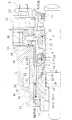
図1は、本発明の実施の形態1に係る高温用デッドエンドシールの全体を説明する正面断面図である。
図1において、参照符号1は、石油精製、石油化学および製鉄化学等において200℃を越えるような高温液、たとえば、石油精製プラントの減圧蒸留設備の熱油を扱う機器、例えば、ポンプ等における軸封部のハウジング、参照符号2はハウジング1にボルト3等の固定手段により装着されるシールカバーである。また、図中左側が機内側、図中右側が大気側(機外側)である。
[Embodiment 1]
FIG. 1 is a front cross-sectional view illustrating the entirety of a high-temperature dead end seal according to
In FIG. 1,
この実施の形態によるメカニカルシールは、回転軸4とハウジング1との間に形成した軸封部5に装着されて、回転軸4とハウジング1との間をシールするメカニカルシールであって、シールカバー2側に装着されたカラー6と、該カラー6に連結されるベローズ7と、該ベローズ7に連結されるリテーナ8と、該リテーナ8の端面とラップジョイントをもって密封的に接触するシールリング9と、回転軸4側に取り付けられるメイティングリング10とを備えている。
なお、本発明において、シールリング9のリテーナ8による保持構造を、上記したラップジョイントによらず、シールリング9の外周側をリテーナ8の内周側に嵌合させた公知の固定環構造であってもよいことはもちろんである。
The mechanical seal according to this embodiment is a mechanical seal that is mounted on a
In the present invention, the holding structure of the
ハウジング1には冷却ジャケット12が設けられている。
なお、本例ではハウジング1に既存の冷却ジャケット12が設けられている場合を示しているが、新たに設ける必要はない。
また、スタフィングボックス13の奥(機内側)にはスロートブッシュ14が取り付けられており、機内側から軸封部5に流入するシール液に対し絞りを形成している。
The
In addition, although the case where the existing
A
カラー6は、金属から形成される筒状をなすものであって、環状のガスケット15を介してシールカバー2側に取り付けられている。
ベローズ7は、打抜き加工等によって波形環状に形成した金属製のダイアフラム板を複数枚一列に並べて、隣接するダイアフラム板の外径部間及び内径部間をガス溶接等によって交互に連結して、全体を蛇腹筒状に形成したものであって、一端がカラー6側にガス溶接等によって一体に連結されるようになっている。
The
The
リテーナ8は、金属から形成され筒状をなすものであって、ベローズ7の他端がガス溶接等によって一体に連結されるようになっている。リテーナ8の材料はベローズ7の材料と同一か、あるいは熱膨張係数がほぼ近似した異種材料からなっている。
リテーナ8、ベローズ7およびカラー6を溶接により一体物として製作後、これらの全表面に特殊窒化クロムや窒化チタンなどの10μm以下の厚みの耐食・耐摩耗性のイオンプレーティングを均一に施工する。これにより、リテーナ8、ベローズ7およびカラー6の全表面が均一な耐食性をもつので、耐食性の低い材料で構成されていても、イオンプレーティングの耐食性が全体の耐食性となり、材料選定の制限が大幅に少なくなる。
The
After the
シールリング9は、炭化珪素、カーボン、その他のセラミックス等から形成される筒状をなすものであって、メイティングリング10との摺動面において回転軸4の軸線に垂直なシール面16を形成している。
シールリング9は両端面にラッピング仕上げされたシール端面を持っており、シールリング9とリテーナ8とは分離した構造となっており、リテーナ8のシールリング9側端面もラッピング仕上げされたシール端面を持ち、両者の密封は、ラッピング面を合わせて密封するラップジョイント構造を採用している。シールリング9とリテーナ8とは分離した構造となっているため、高温雰囲気でもメイティングリング10と摺動するシールリング9のシール端面の平面度は、熱膨張差による影響を受けないので、密封性が保たれる。また、リテーナ8自体の圧力変形や熱変形にも影響されることがない。さらに、焼嵌めや圧入、その後の熱処理などの特殊工程の必要がなく、それに伴いジグ類も不要となるので、コスト低減および工数低減が図れる。また、シールリング9の交換が容易となる。
The
The
リテーナ8のシール端面とシールリング9のシール端面とはベローズ7のばね荷重および流体圧による押し付け力で互いに密封的に接触するが、リテーナ8のシール端面は、シールリング9が回転しないので回転による摺動はしない、ほぼ静止の密封面である。シールリング9の反メイティングリング側のシール端面の面幅はメイティングリング10と摺動するシール端面の面幅とほぼ同じかそれよりもやや狭くしてある。
The seal end surface of the
シールリング9、リテーナ8、ベローズ7及びカラー6の内周側には所定の間隔をおいて筒状のバッフルスリーブ17が取り付けられ、このバッフルスリーブ17によってシールカバー2に設けられたクエンチング液供給孔35から供給されるクエンチング液がシール面16に確実に導かれるようになっている。バッフルスリーブ17は、SUS630などの硬い材料で製作されるか、硬質クロムメッキ、特殊窒化クロム、あるいは窒化チタンなどの10μm以下の厚みの耐食・耐摩耗性のイオンプレーティングが施されている。
大気側に位置するシールカバー2の内周部と回転軸4外周部との間には、クエンチシール21が設けられて、クエンチング液供給孔35からバッフルスリーブ17側に供給されるクエンチング液をシールしている。22は、クエンチシール21のホルダーであって、シールカバー2にボルト23によって固定されている。
A
A quenching
回転軸4のメイティングリング10の位置する部分に段部18が形成され、該段部18にメイティングリング10を支持するリテーナ11がガスケット19を介して密封的に装着されている。メイティングリング10はパッキン20を介してリテーナ11に取り付けられている。メイティングリング10は、炭化珪素、カーボン、その他のセラミックス等から形成される筒状をなすものであって、軸線方向の一端面はシールリング9のシール端面と接触する回転軸4の軸線に垂直なシール面16を形成する。リテーナ11の全表面には硬質クロムメッキ、特殊窒化クロム、あるいは窒化チタンなどの10μm以下の厚みの耐食・耐摩耗性のイオンプレーティングが施されている。
A
シールリング9の反メイティングリング側の内周側に段部24を形成するとともに、リテーナ8のシールリング側の内周側にも段部25を形成し、これら両段部24、25に、シールリング9の材料と同一材料か熱膨張係数がシールリング9の材料と同じかそれよりも小さい材料、例えば、SiCで作られたケース26を径方向に微小隙間をもって嵌入させ、リテーナ8とシールリング9との芯出しをするようになっている。ケース26が密封液中に無いので、固着するような性状の液や固形分の多い液の場合でも、ケース26とシールリング9との隙間およびケース26とリテーナ8との隙間において密封液が固着することが無く、かつ、ケース26がクエンチング液側に配置され、クエンチング液で隙間が常時洗浄されているので、ラップジョイント部が常時スムーズにスリップすることができる。さらに、熱膨張によるシールリング9とケース26との隙間減少が防止でき、シールリング9が拘束されることがない。
A step portion 24 is formed on the inner peripheral side of the
図2は、図1のA−A断面図であって、図2に示すように、シールリング9の内周側には1個または複数個の切り欠き27が設けられている。一方、シールカバー2に固定されたバッフルスリーブ17の先端が、図1に示すように、シールリング9のシール端面側の近くまで伸びて、その先端に、図2に示すように、シールリング9の切り欠き27と微小隙間を持って係合する雄型の歯部28が形成されている。シールリング9の切り欠き27とバッフルスリーブ17の歯部28とは軸方向に可動可能に互いに噛み合うクラッチ構造を形成している。
2 is a cross-sectional view taken along the line AA of FIG. 1, and as shown in FIG. 2, one or a plurality of
上記のように、シールリング9とリテーナ8とは分離した構造となっていること、シールリング9とリテーナ8との密封はラップジョイント構造となっていること、および、シールリング9とバッフルスリーブ17とは軸方向に可動可能に互いに噛み合うクラッチ構造となっていることから、シールリング9のシール端面の摺動トルクはバッフルスリーブ17が受けることになり、ベローズ7に摺動トルクが伝わらないため、シール面の潤滑不安定によりシールリング9のシール端面にスティックスリップが発生しても、ラップジョイント部で自在に滑ることにより、ベローズ7がスティックスリップの影響を受けることがない。
As described above, the
バッフルスリーブ17の外周面とリテーナ8の内周面との隙間を円周方向の特定部分、例えば、4等配となる部分に隙間を狭くした絞り部を形成し、ベローズ7に振動が起きた場合でも、ベローズ7の振れ止めを行うようにしている。このため、ベローズの疲労を先延ばしにでき、耐久性を確保できる。本例では、バッフルスリーブ17のリテーナ8と対峙する外周面側を部分的に厚くして隙間を狭くした絞り部を形成しているが、これに限らず、リテーナ8の内周側を部分的に小径にしてもよい。
また、リテーナ8の内周部には、1個または複数個の切り欠き29を設け、クエンチング液供給孔35から供給され、バッフルスリーブ17によってシール面16に誘導されてきたクエンチング液の通路を形成している。このため、クエンチング液は、バッフルスリーブ17によりシール面16に誘導され、シール面16からの微小な漏れ液を洗浄排出するが、その際、リテーナ8およびシールリング9内周の切り欠きがクエンチング液の通路を形成することになり、クエンチング液を停滞することなく流すことができる。
A narrowed narrow portion is formed in a specific portion in the circumferential direction, for example, a portion that is evenly spaced, for example, a gap between the outer peripheral surface of the
Further, one or a plurality of
軸封部5に装着されたメカニカルシール部の外周に位置するハウジング1の内面に沿って中空円筒状の冷却ジャケット30が配設されている。中空円筒状の冷却ジャケット30は、2つの部材、すなわち、管状の内周側部材30−1および管状の外周側部材30−2から作られており、これらの部材の一端(右端)はシールカバー2に接続され、他端(左端)はスタフィングボックス13の機内側のスロートブッシュ14の近傍まで伸びている。ハウジング1の内面に沿って中空円筒状の冷却ジャケット30が配設されることから、冷却ジャケット30の内周とメイティングリング10を支持するリテーナ11の外周との間には絞り部41が形成されることになる。
A hollow
内周側部材30−1および外周側部材30−2は、通常、両方を熱伝導率の大きい金属材料で形成する。
また、本例では、内周側部材30−1はシールカバー2と一体に形成され、断面が略L字型をしている。外周側部材30−2は、内周側部材30−1と同じく断面が略L字型であって内周側部材30−1の蓋の役割をしており、ハウジング1の内周面に沿うように配設されており、内周側部材30−1との間に冷却媒体であるスチーム(温度約120℃程度)あるいは水が流れることのできる中空円筒状の冷却室31を有するように形成されている。
Both the inner peripheral member 30-1 and the outer peripheral member 30-2 are usually formed of a metal material having a high thermal conductivity.
Further, in this example, the inner peripheral member 30-1 is formed integrally with the
内周側部材30−1と外周側部材30−2とは、両端の溶接部32、33で溶接され、右端においてシールカバー2と一体になっている。外周側部材30−2の右側の立ち上がり壁34とハウジング1の右側面との間には環状のガスケット36が配設されて両部材間をシールしている。また、内周側部材30−1と外周側部材30−2との左端側には、パーフロロエラストマ、フッ素ゴム等の材料からなるOリング37が装着されている、このOリング37は、溶接部32の溶接が万一不良の時に、スチームや水がシール液である熱油に漏れ込んで、急激に沸騰して危険なため、それを防止するものである。
The inner peripheral side member 30-1 and the outer peripheral side member 30-2 are welded at the welded
このように、軸封部5に装着されたメカニカルシール部の外周に位置するハウジング1の内面に沿って中空円筒状の冷却ジャケット30が配設されているため、スタフィングボックス内の容積を縮小することができるので、スタフィングボックス内の熱容量が小さくなり、冷却ジャケット30で容易に冷却ができるようになり、メカニカルシール部近傍の温度を下げることができる。また、メカニカルシール部の外周と中空円筒状の冷却ジャケット30内周との間に絞り部が形成されることから、機内側からの高温液の流入を極小に抑えられるので、メカニカルシール部への伝熱が抑えられる。
As described above, since the hollow
中空円筒状の冷却ジャケット30の冷却媒体の出入口38はシールカバー2に設けられている。冷却媒体として水を用いる場合は、中空円筒状の冷却ジャケット30の下方に入口を、上方に出口を配設し、水を下方から上方に向けて供給するようにすることにより、水中に含まれるエアーおよびカルキを抜くことができる。なお、冷却媒体としてスチームを用いる場合は、スチームにはカルキが含まれていないため、出入口をどちらに設けてもよい。
A cooling medium inlet /
〔実施の形態2〕
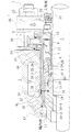
図3は、本発明の実施の形態2に係る高温用デッドエンドシールの全体を説明する正面断面図である。
本実施の形態2に係る高温用デッドエンドシールは、基本構造は実施の形態1と同じであり、図3において、図1と同じ符号は図1の場合と同じ部材を指している。以下、実施の形態1と相違する部分について主に説明する。
[Embodiment 2]
FIG. 3 is a front cross-sectional view illustrating the entire high-temperature dead end seal according to
The basic structure of the high temperature dead end seal according to the second embodiment is the same as that of the first embodiment, and in FIG. 3, the same reference numerals as those in FIG. 1 indicate the same members as in FIG. Hereinafter, the difference from
図3において、中空円筒状の冷却ジャケット30内に形成された冷却室31には、冷却媒体の入口と出口との短絡を防止するフローガイド39を設けている。
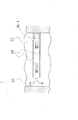
図4は、図3のB−B断面図を示したものであり、フローガイド39は、2枚の遮蔽板を一定間隔をもって配置するようにして構成され、冷却媒体の収容室31の右端に設けられた冷却媒体の入口38−1から冷却媒体をガイドするように左端側に向けて延びており、左端側の冷媒通路40を残して冷却媒体を左右に分流するように形成されている。このように、フローガイド39を設けることにより、冷却媒体が入口から出口にショートパスして流れることが防止されるため、冷却効果を向上させることができる。
In FIG. 3, the cooling
FIG. 4 is a cross-sectional view taken along the line B-B of FIG. 3, and the
1 ハウジング
2 シールカバー
3 ボルト
4 回転軸
5 軸封部
6 カラー
7 ベローズ
8 リテーナ
9 シールリング
10 メイティングリング
11 リテーナ
12 冷却ジャケット
13 スタフィングボックス
14 スロートブッシュ
15 ガスケット
16 シール面
17 バッフルスリーブ
18 段部
19 ガスケット
20 パッキン
21 クエンチシール
22 ホルダー
23 ボルト
24 段部
25 段部
26 ケース
27 切り欠き
28 雄型の歯部
29 切り欠き
30 冷却ジャケット
30−1内周側部材
30−2外周側部材
31 冷却室
32 溶接部
33 溶接部
34 立ち上がり壁
35 クエンチング液供給孔
36 ガスケット
37 Oリング
38 冷却媒体の出入口
39 フローガイド
40 冷媒通路
41 絞り部
DESCRIPTION OF
11 Retainer
12 Cooling jacket
13
Claims (5)
Priority Applications (1)
| Application Number | Priority Date | Filing Date | Title |
|---|---|---|---|
| JP2009060556A JP5259463B2 (en) | 2009-03-13 | 2009-03-13 | High temperature dead end seal |
Applications Claiming Priority (1)
| Application Number | Priority Date | Filing Date | Title |
|---|---|---|---|
| JP2009060556A JP5259463B2 (en) | 2009-03-13 | 2009-03-13 | High temperature dead end seal |
Publications (2)
| Publication Number | Publication Date |
|---|---|
| JP2010216491A JP2010216491A (en) | 2010-09-30 |
| JP5259463B2 true JP5259463B2 (en) | 2013-08-07 |
Family
ID=42975554
Family Applications (1)
| Application Number | Title | Priority Date | Filing Date |
|---|---|---|---|
| JP2009060556A Active JP5259463B2 (en) | 2009-03-13 | 2009-03-13 | High temperature dead end seal |
Country Status (1)
| Country | Link |
|---|---|
| JP (1) | JP5259463B2 (en) |
Families Citing this family (8)
| Publication number | Priority date | Publication date | Assignee | Title |
|---|---|---|---|---|
| JP5613529B2 (en) * | 2010-11-09 | 2014-10-22 | 日本ピラー工業株式会社 | mechanical seal |
| WO2013187322A1 (en) * | 2012-06-13 | 2013-12-19 | イーグル工業株式会社 | Breakdown-predicting mechanical seal system for sealing high-temperature seal fluid |
| EP2910823A4 (en) * | 2012-10-19 | 2016-05-18 | Eagleburgmann Japan Co Ltd | Bellows seal |
| EP3168509A1 (en) * | 2014-07-11 | 2017-05-17 | Eagle Industry Co., Ltd. | Mechanical seal |
| WO2018123617A1 (en) * | 2016-12-27 | 2018-07-05 | イーグル工業株式会社 | Mechanical seal |
| JP6878103B2 (en) * | 2017-04-10 | 2021-05-26 | 日本ピラー工業株式会社 | mechanical seal |
| CN112377453B (en) * | 2020-12-07 | 2024-08-20 | 江苏华青流体科技有限公司 | A mechanical sealing device for high temperature hot water pump |
| CN114294112B (en) * | 2021-10-20 | 2023-06-13 | 中国航发四川燃气涡轮研究院 | Double-channel pipeline device with transfer sealing structure |
Family Cites Families (7)
| Publication number | Priority date | Publication date | Assignee | Title |
|---|---|---|---|---|
| JPH0448376Y2 (en) * | 1987-05-19 | 1992-11-13 | ||
| JPH0247314Y2 (en) * | 1987-06-26 | 1990-12-12 | ||
| JPH05240419A (en) * | 1992-02-26 | 1993-09-17 | Kobe Steel Ltd | Cooling structure for burner |
| JPH083767Y2 (en) * | 1992-07-09 | 1996-01-31 | 日本ピラー工業株式会社 | Shaft seal device |
| JP3017462B2 (en) * | 1997-09-02 | 2000-03-06 | 株式会社酉島製作所 | Cooling device for mechanical seal |
| JP3864359B2 (en) * | 1998-07-29 | 2006-12-27 | イーグル工業株式会社 | mechanical seal |
| JP3710702B2 (en) * | 2000-11-14 | 2005-10-26 | イーグル工業株式会社 | Tandem seal |
-
2009
- 2009-03-13 JP JP2009060556A patent/JP5259463B2/en active Active
Also Published As
| Publication number | Publication date |
|---|---|
| JP2010216491A (en) | 2010-09-30 |
Similar Documents
| Publication | Publication Date | Title |
|---|---|---|
| JP5259463B2 (en) | High temperature dead end seal | |
| JP5557752B2 (en) | mechanical seal | |
| CN101031745B (en) | mechanical seal | |
| JP5271260B2 (en) | Mechanical seal device | |
| JP5615267B2 (en) | Mechanical seal device | |
| JP4734171B2 (en) | mechanical seal | |
| JP5712067B2 (en) | High temperature fluid shaft seal device | |
| WO2016058457A1 (en) | Bushing for cooling dual-side mechanical seal friction pair and centrifugal pump cooling system thereof | |
| JP6104820B2 (en) | Failure predictive mechanical seal system for sealing high temperature sealed fluid | |
| JP6124901B2 (en) | mechanical seal | |
| JP6713462B2 (en) | Molten metal transfer pump | |
| WO2016059883A1 (en) | Sealing device | |
| JP5124784B2 (en) | Mechanical seal device | |
| WO2006137305A1 (en) | Mechanical seal | |
| CN110685921A (en) | Cooling device used when vertical multistage centrifugal pump conveys high-temperature fluid | |
| JP6878103B2 (en) | mechanical seal | |
| JP4577487B2 (en) | Mechanical seal device | |
| JP4797097B2 (en) | Outside type mechanical seal | |
| CN110088515B (en) | Mechanical sealing element | |
| JP2018194148A (en) | Shaft seal device | |
| JP6542105B2 (en) | Sealing device | |
| JP2015183790A (en) | mechanical seal | |
| JP5924770B2 (en) | mechanical seal | |
| JP5334656B2 (en) | Sealing device | |
| CN108131298A (en) | A kind of immersed pump |
Legal Events
| Date | Code | Title | Description |
|---|---|---|---|
| A621 | Written request for application examination |
Free format text: JAPANESE INTERMEDIATE CODE: A621 Effective date: 20111118 |
|
| A977 | Report on retrieval |
Free format text: JAPANESE INTERMEDIATE CODE: A971007 Effective date: 20121203 |
|
| A131 | Notification of reasons for refusal |
Free format text: JAPANESE INTERMEDIATE CODE: A131 Effective date: 20130131 |
|
| A521 | Request for written amendment filed |
Free format text: JAPANESE INTERMEDIATE CODE: A523 Effective date: 20130319 |
|
| TRDD | Decision of grant or rejection written | ||
| A01 | Written decision to grant a patent or to grant a registration (utility model) |
Free format text: JAPANESE INTERMEDIATE CODE: A01 Effective date: 20130423 |
|
| A61 | First payment of annual fees (during grant procedure) |
Free format text: JAPANESE INTERMEDIATE CODE: A61 Effective date: 20130424 |
|
| FPAY | Renewal fee payment (event date is renewal date of database) |
Free format text: PAYMENT UNTIL: 20160502 Year of fee payment: 3 |
|
| R150 | Certificate of patent or registration of utility model |
Ref document number: 5259463 Country of ref document: JP Free format text: JAPANESE INTERMEDIATE CODE: R150 Free format text: JAPANESE INTERMEDIATE CODE: R150 |
|
| R250 | Receipt of annual fees |
Free format text: JAPANESE INTERMEDIATE CODE: R250 |
|
| R250 | Receipt of annual fees |
Free format text: JAPANESE INTERMEDIATE CODE: R250 |
|
| R250 | Receipt of annual fees |
Free format text: JAPANESE INTERMEDIATE CODE: R250 |
|
| R250 | Receipt of annual fees |
Free format text: JAPANESE INTERMEDIATE CODE: R250 |
|
| R250 | Receipt of annual fees |
Free format text: JAPANESE INTERMEDIATE CODE: R250 |
|
| R250 | Receipt of annual fees |
Free format text: JAPANESE INTERMEDIATE CODE: R250 |
|
| R250 | Receipt of annual fees |
Free format text: JAPANESE INTERMEDIATE CODE: R250 |
|
| R250 | Receipt of annual fees |
Free format text: JAPANESE INTERMEDIATE CODE: R250 |
|
| R250 | Receipt of annual fees |
Free format text: JAPANESE INTERMEDIATE CODE: R250 |
|
| R250 | Receipt of annual fees |
Free format text: JAPANESE INTERMEDIATE CODE: R250 |
|
| R250 | Receipt of annual fees |
Free format text: JAPANESE INTERMEDIATE CODE: R250 |