JP5259461B2 - Method of forming integrally molded product of metallic glass and polymer material, and molding device for integrally molded product - Google Patents
Method of forming integrally molded product of metallic glass and polymer material, and molding device for integrally molded product Download PDFInfo
- Publication number
- JP5259461B2 JP5259461B2 JP2009058467A JP2009058467A JP5259461B2 JP 5259461 B2 JP5259461 B2 JP 5259461B2 JP 2009058467 A JP2009058467 A JP 2009058467A JP 2009058467 A JP2009058467 A JP 2009058467A JP 5259461 B2 JP5259461 B2 JP 5259461B2
- Authority
- JP
- Japan
- Prior art keywords
- mold
- metal glass
- cooling
- polymer material
- glass
- Prior art date
- Legal status (The legal status is an assumption and is not a legal conclusion. Google has not performed a legal analysis and makes no representation as to the accuracy of the status listed.)
- Expired - Fee Related
Links
- 238000000034 method Methods 0.000 title claims description 71
- 239000002861 polymer material Substances 0.000 title claims description 67
- 239000005300 metallic glass Substances 0.000 title claims description 61
- 238000000465 moulding Methods 0.000 title claims description 47
- 238000001816 cooling Methods 0.000 claims description 126
- 229910052751 metal Inorganic materials 0.000 claims description 124
- 239000002184 metal Substances 0.000 claims description 121
- 239000011521 glass Substances 0.000 claims description 113
- 238000002347 injection Methods 0.000 claims description 48
- 239000007924 injection Substances 0.000 claims description 48
- 239000000463 material Substances 0.000 claims description 22
- 238000005979 thermal decomposition reaction Methods 0.000 claims description 17
- 238000009434 installation Methods 0.000 claims description 11
- 238000007493 shaping process Methods 0.000 claims description 11
- 238000002844 melting Methods 0.000 claims description 10
- 230000008018 melting Effects 0.000 claims description 10
- 239000007769 metal material Substances 0.000 claims description 2
- 230000003287 optical effect Effects 0.000 description 31
- 239000004417 polycarbonate Substances 0.000 description 12
- 229920000515 polycarbonate Polymers 0.000 description 12
- 238000003825 pressing Methods 0.000 description 9
- 230000009477 glass transition Effects 0.000 description 8
- 238000004519 manufacturing process Methods 0.000 description 7
- 239000000498 cooling water Substances 0.000 description 6
- 238000002425 crystallisation Methods 0.000 description 6
- 230000008025 crystallization Effects 0.000 description 6
- 229910000975 Carbon steel Inorganic materials 0.000 description 4
- 239000010962 carbon steel Substances 0.000 description 4
- 230000005484 gravity Effects 0.000 description 4
- 229920003229 poly(methyl methacrylate) Polymers 0.000 description 4
- 239000012298 atmosphere Substances 0.000 description 3
- 238000005260 corrosion Methods 0.000 description 3
- 230000007797 corrosion Effects 0.000 description 3
- 239000013078 crystal Substances 0.000 description 3
- 238000010438 heat treatment Methods 0.000 description 3
- 229920000642 polymer Polymers 0.000 description 3
- 239000004800 polyvinyl chloride Substances 0.000 description 3
- 229910017535 Cu-Al-Ni Inorganic materials 0.000 description 2
- 229910018104 Ni-P Inorganic materials 0.000 description 2
- 229910018536 Ni—P Inorganic materials 0.000 description 2
- 150000001925 cycloalkenes Chemical class 0.000 description 2
- 238000001514 detection method Methods 0.000 description 2
- 229920000915 polyvinyl chloride Polymers 0.000 description 2
- 229920005989 resin Polymers 0.000 description 2
- 239000011347 resin Substances 0.000 description 2
- 239000013077 target material Substances 0.000 description 2
- 229910018182 Al—Cu Inorganic materials 0.000 description 1
- 229910018507 Al—Ni Inorganic materials 0.000 description 1
- 239000000853 adhesive Substances 0.000 description 1
- 230000001070 adhesive effect Effects 0.000 description 1
- 239000000956 alloy Substances 0.000 description 1
- 229910045601 alloy Inorganic materials 0.000 description 1
- 238000005280 amorphization Methods 0.000 description 1
- 230000000052 comparative effect Effects 0.000 description 1
- 230000008878 coupling Effects 0.000 description 1
- 238000010168 coupling process Methods 0.000 description 1
- 238000005859 coupling reaction Methods 0.000 description 1
- 238000000354 decomposition reaction Methods 0.000 description 1
- 239000012530 fluid Substances 0.000 description 1
- 238000007496 glass forming Methods 0.000 description 1
- PCHJSUWPFVWCPO-UHFFFAOYSA-N gold Chemical compound [Au] PCHJSUWPFVWCPO-UHFFFAOYSA-N 0.000 description 1
- 239000010931 gold Substances 0.000 description 1
- 229910052737 gold Inorganic materials 0.000 description 1
- 229910052747 lanthanoid Inorganic materials 0.000 description 1
- 150000002602 lanthanoids Chemical class 0.000 description 1
- 239000000155 melt Substances 0.000 description 1
- 239000000203 mixture Substances 0.000 description 1
- 239000012768 molten material Substances 0.000 description 1
- 239000012299 nitrogen atmosphere Substances 0.000 description 1
- 229920003023 plastic Polymers 0.000 description 1
- 239000004033 plastic Substances 0.000 description 1
- 238000007711 solidification Methods 0.000 description 1
- 230000008023 solidification Effects 0.000 description 1
- 230000003746 surface roughness Effects 0.000 description 1
- 229920005992 thermoplastic resin Polymers 0.000 description 1
- 230000007704 transition Effects 0.000 description 1
Images
Landscapes
- Moulds For Moulding Plastics Or The Like (AREA)
- Injection Moulding Of Plastics Or The Like (AREA)
Description
本発明は、金属ガラスからなる部分と高分子材料からなる部分とで構成される一体成形品の成形方法及びその成形装置に関する。 The present invention relates to a method for molding an integrally molded article composed of a part made of metallic glass and a part made of a polymer material, and a molding apparatus therefor.
レンズなどの光学素子と、該光学素子を保持する枠体とからなる光学素子デバイスは、従来、予め光学素子と枠体とを別々に製造した後に、枠体に光学素子を嵌合固定または接着固定させることにより製造されていた。しかし、近年、光学素子デバイスの小型化により、上記のような製造方法では、必要な組み立て精度を確保することができない問題があった。このため、プラスチックを加熱軟化させた状態で金型によって押圧することで光学素子を成形した後に、金型を型開きせずに、成形された光学素子となる部分を基準として枠体となる部分を射出成形する製造方法が提案されている(例えば、特許文献1参照)。この製造方法によれば、光学素子を成形した後にそのままの状態で光学素子の金型の位置を基準に枠体が光学素子に結合された状態で成形されるための、光学素子と枠体との結合精度を高めることができるとされている。 Conventionally, an optical element device composed of an optical element such as a lens and a frame body that holds the optical element is manufactured by separately manufacturing the optical element and the frame body in advance, and then fixing or bonding the optical element to the frame body. It was manufactured by fixing. However, in recent years, due to the miniaturization of the optical element device, there has been a problem that the above-described manufacturing method cannot ensure the required assembly accuracy. For this reason, after forming an optical element by pressing with a mold in a state where the plastic is heated and softened, a part that becomes a frame with reference to the part that becomes the molded optical element without opening the mold Has been proposed (for example, see Patent Document 1). According to this manufacturing method, after molding the optical element, the optical element and the frame body are molded in a state in which the frame body is bonded to the optical element with reference to the position of the mold of the optical element. It is said that the coupling accuracy can be improved.
一方、近年、光学素子デバイスの枠体に使用される材料としては、金属ガラスが注目されている。金属ガラスは、結晶化した金属材料と比較して、強度、耐久性、耐食性に優れているとともに高い寸法精度をもって射出成形を行うことが可能であり、光学素子デバイスの製造においても、さらなる小型化、形状の複雑化、高精度化などの点で採用が試みられている。 On the other hand, in recent years, metallic glass has attracted attention as a material used for a frame of an optical element device. Metal glass is superior in strength, durability, and corrosion resistance, and can be injection-molded with high dimensional accuracy, compared to crystallized metal materials. Further miniaturization in optical element device manufacturing Adoption has been attempted in terms of complexity of shape and higher accuracy.
しかしながら、特許文献1の製造方法において、枠体を金属ガラスで形成しようとすれば、高分子材料を射出する温度と比較して金属ガラスを射出する温度の方が高いことから、光学素子を形成する高分子材料が金属ガラスを射出する際の熱により変形してしまう問題があった。このため、光学素子デバイスにおいて、枠体を金属ガラスで形成する場合には、嵌合固定あるいは接着固定によらなければならず、結果必要な精度を確保することができない問題があった。 However, in the manufacturing method of Patent Document 1, if the frame is made of metal glass, the temperature at which the metal glass is injected is higher than the temperature at which the polymer material is injected. There is a problem that the polymer material to be deformed due to heat when injecting the metal glass. For this reason, in the optical element device, when the frame body is formed of metal glass, it has to be based on fitting fixing or adhesive fixing, and as a result, there is a problem that the required accuracy cannot be ensured.
この発明は、上述した事情に鑑みてなされたものであって、金属ガラスからなる部分と高分子材料からなる部分とで構成される一体成形品を精度良く製造することが可能な金属ガラスと高分子材料との一体成形品の成形方法、及び、一体成形品用成形装置を提供するものである。 The present invention has been made in view of the above-described circumstances, and is a metal glass capable of accurately manufacturing an integrally molded product composed of a portion made of metal glass and a portion made of a polymer material. An object of the present invention is to provide a molding method of an integrally molded product with a molecular material and a molding apparatus for the integrally molded product.
上記課題を解決するために、この発明は以下の手段を提案している。
本発明は、金属ガラスで形成された第一の部分と、高分子材料で形成された第二の部分とで構成される金属ガラスと高分子材料との一体成形品の成形方法であって、少なくとも一部が交換可能に構成され前記第一の部分と対応する形状に形成された金型のキャビティ内に、前記金属ガラスを融点以上に加熱した状態で射出する金属ガラス射出工程と、前記金型の前記キャビティ内に射出された前記金属ガラスを、臨界冷却速度以上の冷却速度で、前記高分子材料の熱分解温度以下となるまで冷却する金属ガラス冷却工程と、前記金型の少なくとも一部を交換して、キャビティを前記第二の部分と対応する形状に形成する金型交換工程と、前記第二の部分と対応する形状に形成された前記金型の前記キャビティ内に、前記高分子材料を射出する高分子材料射出工程とを備えることを特徴としている。
In order to solve the above problems, the present invention proposes the following means.
The present invention is a method for molding an integrally molded product of a metal glass and a polymer material composed of a first portion formed of metal glass and a second portion formed of polymer material, A metal glass injection step of injecting the metal glass in a state where the metal glass is heated to a melting point or more in a cavity of a mold that is configured to be at least partially exchangeable and has a shape corresponding to the first part; A metal glass cooling step of cooling the metal glass injected into the cavity of the mold at a cooling rate equal to or higher than a critical cooling rate until the temperature is equal to or lower than a thermal decomposition temperature of the polymer material, and at least a part of the mold A mold exchanging step of forming a cavity in a shape corresponding to the second part, and the polymer in the cavity of the mold formed in a shape corresponding to the second part. Inject material It is characterized in that it comprises a molecular material injection step.
また、本発明は、金属ガラスで形成された第一の部分と、高分子材料で形成された第二の部分とで構成される金属ガラスと高分子材料との一体成形品用成形装置であって、少なくとも一部を交換することで、キャビティを前記第一の部分と前記第二の部分とのそれぞれに対応した形状に切換可能な金型が設置される金型設置部と、該金型設置部に設置された前記金型の少なくとも一部を交換可能な金型交換手段と、前記金型設置部に設置された前記金型の前記キャビティ内に前記金属ガラスと高分子材料とのそれぞれを射出する射出手段と、前記金型の前記キャビティ内に射出された前記金属ガラスを臨界冷却速度以上の冷却速度で所定温度まで冷却可能な冷却手段とを備えることを特徴としている。 In addition, the present invention is a molding apparatus for an integrally molded product of a metal glass and a polymer material, which is composed of a first portion formed of metal glass and a second portion formed of polymer material. A mold installation part in which a mold capable of switching the cavity to a shape corresponding to each of the first part and the second part by replacing at least a part thereof, and the mold A mold exchanging means capable of exchanging at least a part of the mold installed in the installation section, and each of the metallic glass and the polymer material in the cavity of the mold installed in the mold installation section. And a cooling means capable of cooling the metallic glass injected into the cavity of the mold to a predetermined temperature at a cooling rate equal to or higher than a critical cooling rate.
この発明に係る金属ガラスと高分子材料との一体成形品の成形方法及び一体成形品用成形装置によれば、金属ガラス射出工程として、キャビティを第一の部分と対応する形状として金型を金型設置部に設置し、射出手段によって該金型のキャビティ内に融点以上に加熱した金属ガラスを射出する。そして、金属ガラス冷却工程として、冷却手段によって金型のキャビティ内に射出した金属ガラスを臨界冷却速度以上の冷却速度で高分子材料の熱分解温度以下となるまで冷却する。このため、金型のキャビティ内において、一体成形品の第一の部分を金属ガラスによって結晶化してしまうことなく精度良く形成することができる。次に、金型交換工程として、金型交換手段によって金型の少なくとも一部を交換することで、第二の部分と対応する形状のキャビティを形成することができる。そして、高分子材料射出工程として、射出手段によって金型のキャビティ内に第二の部分となる高分子材料を射出することで、第一の部分となる金属ガラスと第二の部分となる高分子材料が一体となる一体成形品が成形されることとなる。ここで、金属ガラス冷却工程では、高分子材料の熱分解温度以下となるまで冷却していることで、第二の部分となる高分子材料を熱の影響を受けることなく射出成形することができる。また、予め第一の部分を金属ガラスで形成しておくことで、第一の部分と対応させて第二の部分を精度良く成形することができる。 According to the method for molding an integrally molded product of metal glass and polymer material and the molding apparatus for an integrally molded product according to the present invention, as a metal glass injection process, a mold is formed with a cavity corresponding to the first part. It is installed in the mold installation part, and the metallic glass heated to the melting point or more is injected into the mold cavity by the injection means. Then, as the metallic glass cooling step, the metallic glass injected into the mold cavity by the cooling means is cooled at a cooling rate equal to or higher than the critical cooling rate until it becomes equal to or lower than the thermal decomposition temperature of the polymer material. For this reason, in the cavity of a metal mold | die, it can form accurately, without crystallizing the 1st part of an integrally molded product with metal glass. Next, as a mold exchanging step, a cavity having a shape corresponding to the second part can be formed by exchanging at least a part of the mold by the mold exchanging means. Then, as the polymer material injection step, the polymer material that becomes the second part is injected into the cavity of the mold by the injection means, so that the metal glass that becomes the first part and the polymer that becomes the second part An integrally molded product in which the materials are integrated is formed. Here, in the metal glass cooling step, the polymer material to be the second part can be injection-molded without being affected by heat by cooling until the temperature is lower than the thermal decomposition temperature of the polymer material. . In addition, by forming the first portion in advance with metallic glass, the second portion can be accurately formed in correspondence with the first portion.
また、上記の金属ガラスと高分子材料との一体成形品の成形方法において、前記金属ガラス射出工程の前に、前記金型を所定温度まで冷却する金型冷却工程を備え、前記金属ガラス冷却工程は、前記金型冷却工程で冷却された前記金型と、該金型の前記キャビティ内に射出された前記金属ガラスとの温度差によって行われることがより好ましいとされている。 Further, in the method for molding an integrally molded product of the metal glass and the polymer material, the metal glass cooling step includes a mold cooling step for cooling the mold to a predetermined temperature before the metal glass injection step. Is more preferably performed by a temperature difference between the mold cooled in the mold cooling step and the metal glass injected into the cavity of the mold.
また、上記の金属ガラスと高分子材料との一体成形品用成形装置において、前記冷却手段は、前記金属ガラスを射出する前の前記金型を冷却し、該金型の前記キャビティ内に前記射出手段によって前記金属ガラスを射出することで、該金属ガラスを臨界冷却速度以上の冷却速度で冷却させることがより好ましいとされている。 In the molding apparatus for an integrally molded article of metal glass and polymer material, the cooling means cools the mold before injecting the metal glass, and the injection into the cavity of the mold. By injecting the metallic glass by means, it is more preferable to cool the metallic glass at a cooling rate higher than the critical cooling rate.
この発明に係る金属ガラスと高分子材料との一体成形品の成形方法及び一体成形品用成形装置によれば、金型冷却工程として、冷却手段により、金型を予め冷却した後に、金属ガラス射出工程を行うことで、金属ガラスは金型のキャビティ内に射出されるのと同時に金属ガラス冷却工程として金型との温度差によって臨界冷却速度以上の冷却速度で高分子材料の熱分解温度以下となるまで冷却されることとなる。上記のように予め金型を冷却することにより金属ガラスを冷却することで、射出するのと同時に正確な温度制御のもと金属ガラスを冷却することができる。 According to the method for molding an integrally molded product of metal glass and polymer material and the molding apparatus for an integrally molded product according to the present invention, the metal glass injection is performed after the mold is cooled in advance by the cooling means as the mold cooling step. By performing the process, the metallic glass is injected into the cavity of the mold, and at the same time as the metallic glass cooling process, the temperature difference from the mold causes a cooling rate that is higher than the critical cooling rate and lower than the thermal decomposition temperature of the polymer material. It will be cooled until. By cooling the metallic glass by cooling the mold in advance as described above, the metallic glass can be cooled under accurate temperature control at the same time as the injection.
また、上記の金属ガラスと高分子材料との一体成形品の成形方法において、前記金属ガラス射出工程で射出される金属ガラスの質量、温度及び比熱に基づいて、前記金属ガラス冷却工程で前記金属ガラスを臨界冷却速度以上の冷却速度で冷却するのに必要な前記金型の熱容量を算出し、該熱容量に応じた材質及び質量に前記金型を設定する金型設定工程を備えることがより好ましいとされている。 Further, in the above-mentioned method for molding an integrally molded product of metal glass and polymer material, the metal glass is cooled in the metal glass cooling step based on the mass, temperature and specific heat of the metal glass injected in the metal glass injection step. It is more preferable to include a mold setting step for calculating the heat capacity of the mold necessary for cooling the mold at a cooling rate equal to or higher than the critical cooling rate, and setting the mold to a material and mass according to the heat capacity. Has been.
この発明に係る金属ガラスと高分子材料との一体成形品の成形方法によれば、金型設定工程として、金属ガラス射出工程で射出される金属ガラスの質量、温度及び比熱に基づいて、金属ガラス冷却工程で金属ガラスを臨界冷却速度以上の冷却速度で冷却するのに必要な金型の熱容量を算出し、該熱容量となるように金型の材質及び質量を設定した後に、金属ガラス射出工程及び金属ガラス冷却工程を実施する。このため、射出された金属ガラスを臨界冷却速度以上の冷却速度で、かつ、高分子材料の熱分解温度以下まで、正確に温度制御して冷却することができる。 According to the method for molding an integrally molded product of metal glass and polymer material according to the present invention, as a mold setting process, based on the mass, temperature and specific heat of the metal glass injected in the metal glass injection process, the metal glass After calculating the heat capacity of the mold necessary for cooling the metal glass at a cooling rate equal to or higher than the critical cooling rate in the cooling process, and setting the material and mass of the mold so as to be the heat capacity, the metal glass injection process and A metal glass cooling process is implemented. For this reason, the injected metal glass can be cooled by accurately controlling the temperature at a cooling rate equal to or higher than the critical cooling rate and below the thermal decomposition temperature of the polymer material.
本発明の金属ガラスと高分子材料との一体成形品の成形方法及び一体成形品用成形装置によれば、金属ガラスからなる部分と高分子材料からなる部分とで構成される一体成形品を精度良く製造することができる。 According to the method for molding an integrally molded product of metal glass and polymer material and the molding apparatus for the integrally molded product of the present invention, an integrally molded product composed of a part made of metal glass and a part made of a polymer material is accurately obtained. Can be manufactured well.
(第1の実施形態)
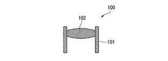
本発明に係る第1の実施形態について、図1から図6を参照して説明する。図1に示す本実施形態の成形装置1は、金属ガラスからなる第一の部分と、高分子材料からなる第二の部分とで構成される一体成形品を製造するためのものである。また、図2は、該一体成形品の一例を示すものであり、光学素子デバイス100を示している。光学素子デバイス100は、金属ガラスからなる第一の部分である略筒状のレンズ枠101と、該レンズ枠101の内部に、同軸として嵌合された高分子材料からなる第二の部分であるレンズ102とで構成されている。レンズ102を形成する高分子材料としては、射出成形可能な熱可塑性樹脂であり、より具体的には、ポリカーボネート、メタクリル酸メチル樹脂(PMMA)、ポリ塩化ビニル(PVC)、シクロオレフィン樹脂などが挙げられる。
(First embodiment)
A first embodiment according to the present invention will be described with reference to FIGS. A molding apparatus 1 according to the present embodiment shown in FIG. 1 is for manufacturing an integrally molded product composed of a first part made of metal glass and a second part made of a polymer material. FIG. 2 shows an example of the integrally molded product, and shows the
また、レンズ枠101を形成する金属ガラスとは、結晶化温度からガラス遷移温度までのガラス遷移領域が20℃以上ある非晶質金属のことである。非晶質金属とは、複数の金属元素が結晶構造を形成せずに凝固(アモルファス化)したものであり、複数の金属元素からなる溶湯をガラス遷移温度以下になるまで、臨界冷却速度以上で急速冷却することにより形成される。そして、このような非晶質金属では、通常の結晶金属が有しているような結晶粒界を有しておらず、該結晶粒界に起因した粒界腐食を生じないことから耐食性に優れている。また、金属ガラスを形成する複数の金属元素としては、3種類以上からなり、それぞれの原子径が互いに12%以上の違いを有し、かつ、互いに引き合う性質を有して化合物化しやすいことがより好ましい。このような金属ガラスとしては、具体的には、例えばZr−Al−Cuや、Ln−Al−Ni(Lnはランタノイド元素のいずれか)の3元系金属ガラスや、Zr−Cu−Al−Niや、Pd−Cu−Ni−Pの4元系金属ガラスなどが挙げられる。
The metallic glass forming the
次に、成形装置1の詳細について説明する。
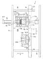
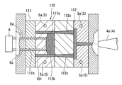
図1に示すように、本実施形態の成形装置1は、固定型111及び可動型112、113で構成される金型110を設置する金型設置部2と、金型110の内、可動型112、113を移動させる移動手段3と、金型110のキャビティ111b内に材料を射出するための射出手段4と、キャビティ111b内の材料を冷却するための冷却手段5とを備える。金型設置部2は、固定型111に取り付けられた型板111aが固定される固定部2aと、固定部2aと対向して配置されて可動型112、113に取り付けられた型板112a、113aが固定され、移動手段3によって固定部2aに向かって進退可能な可動部2bとで構成されている。
Next, the detail of the shaping | molding apparatus 1 is demonstrated.
As shown in FIG. 1, the molding apparatus 1 according to the present embodiment includes a
ここで、金型110の内、固定型111には光学素子デバイス100を成形するためのキャビティ111bが形成されている。また、可動型は、本実施形態では、第一の可動型112と、第二の可動型113と、二つ有していて、第一の可動型112及び第二の可動型113は、金型設置部2の可動部2bにおいて、固定型111に対する進退方向Xに対して略直交する配列方向Yに配列されている。第一の可動型112は、光学素子デバイス100の内、レンズ枠101を形成するためのコア112bを有しており、該第一の可動型112が固定型111に組み付けられてコア112bがキャビティ111bに挿入されることで、該キャビティ111bをレンズ枠101と対応する形状にすることが可能となっている。なお、コア112bの側面は、レンズ枠101の内面において、レンズ102の側面が接合される部分を転写することとなる。このため、コア112bの側面は、レンズ枠101とレンズ102との接合強度を向上させるために、他の部分よりも粗面に形成されていることが望ましく、具体的には、例えば面粗さにおいて最大高さRmaxが25μm程度であることが望ましい。
Here, of the
また、第二の可動型113は、レンズ102を形成するためのコア113bを有しており、レンズ枠101が成形された後に該第二の可動型113が固定型111に組み付けられてコア112bがキャビティ111bに挿入されることで、該キャビティ111bをレンズ102と対応する形状にすることが可能となっている。また、第一の可動型112及び第二の可動型113のそれぞれには、ランナ112c、113cが形成されていて、固定型111と組み付けられる一面側で固定型111のキャビティ111b内と連通可能に開口しているとともに、反対側の他面側で射出手段4によって材料を射出することが可能に開口している。
The second
また、射出手段4は、射出する材料をレンズ枠101を形成する金属ガラスとレンズ102を形成する高分子材料に切り替える図示しない切替部と、対象となる材料を加熱、溶融する図示しない加熱部と、溶融した材料を第一の可動型112または第二の可動型113のランナ112c、113cに射出するノズル4aとを有している。ここで、図示しない加熱部には温度センサが設けられていて、該温度センサの検出結果に基づいて対象となる材料の温度制御を行うことが可能であり、高分子材料においては溶融温度以上熱分解温度以下、金属ガラスにおいてはガラス遷移温度以上結晶化温度以下となる温度に設定することが可能となっている。
The injection means 4 includes a switching unit (not shown) that switches the material to be injected to the metallic glass that forms the
また、冷却手段5は、冷却水を供給する図示しない供給部と、金型110において、キャビティ111b及びランナ112c、113cの周囲に形成され図示しない供給部と接続された冷却配管5aとを有する。金型110には、金型110の温度を測定するための図示しない温度センサが設けられており、冷却手段5は、該温度センサの検出結果に基づいて金型110及び金型110のキャビティ111b内に射出された材料を冷却し、温度制御を行うことが可能となっている。
The cooling means 5 includes a supply unit (not shown) that supplies cooling water, and a
また、移動手段3は、金型設置部2の可動部2bを、第一の可動型112と第二の可動型113との配列方向Yに進退させることが可能なスライダ3aと、スライダ3aを固定型111に対する第一の可動型112及び第二の可動型113の進退方向Xに進退可能としているガイド3bとを有している。このため、第一の可動型112及び第二の可動型113は、スライダ3aによって可動部2bを配列方向Yに進退させてそれぞれ固定型111と対向する位置に配置することが可能であるとともに、対向する位置に配置された状態でガイド3bに沿ってスライダ3aが移動することで固定型111と組付け、または、離脱することが可能である。
Further, the moving
また、固定型111には、第一の可動型112及び第二の可動型113のそれぞれと組み付けられる一面側から、反対側の他面側まで連通する貫通孔111cが形成されている。一面側において貫通孔111cは、第一の可動型112のコア112bが当接される面に開口している。そして、固定型111の他面側には、貫通孔111cに挿入可能なピン6aを有し、固定型111に向かって進退可能な押圧部材6が設けられおり、固定型111に向かって進出し、貫通孔111cにピン6aを挿入させることで、第一の可動型112のコア112bを押圧することが可能となっている。そして、押圧部材6によりコア112bを押圧することで、後述するように固定型111と第一の可動型112が組み付けられてレンズ枠101が射出成形された状態で、移動手段3によって固定型111に対して第一の可動型112を離脱させ、さらに第二の可動型113を組み付けることが可能となり、すなわち押圧部材6と移動手段3とによって金型110の一部を交換する金型交換手段7を構成している。
The fixed
次に、図1から図6に基づいて、本実施形態の一体成形品の成形方法の詳細を説明する。
まず、金型設定工程として、使用する金型110の設定を行う。具体的には、射出する金属ガラスの質量、温度及び比熱に基づいて、後工程の金属ガラス冷却工程で金属ガラスを臨界冷却速度以上の冷却速度で冷却するのに必要な金型110の熱容量を算出する。そして、算出した熱容量に応じて、金型110の材質及び質量を決定し、これにより、金型110においてキャビティ111bの外郭をなす本体部分の形状を決定する。
Next, based on FIGS. 1-6, the detail of the shaping | molding method of the integrally molded product of this embodiment is demonstrated.
First, as a mold setting step, the
次に、図1に示すように、金属ガラス射出工程として、第一の部分となるレンズ枠101を形成する金属ガラスの射出を行う。すなわち、移動手段3を駆動して第一の可動型112が固定型111と対向する位置となるようにした後に、固定型111に対して第一の可動型112を進出させることで両者を組付け、キャビティ111bの形状をレンズ枠101と対応する形状となるようにする。次に、射出手段4において、上記金属ガラスを選択し、該金属ガラスの温度をガラス遷移温度以上結晶化温度以下であるガラス遷移領域となるように設定する。これにより、金属ガラスは、粘性流体となり、射出可能な状態となる。そして、射出手段4は、ノズル4aから第一の可動型112に形成されたランナ112cに金属ガラスを射出する。なお、金属ガラスの射出する量は、金属ガラスの比重と、第一の可動型112のランナ112c及びコア112b、並びに、固定型111のキャビティ111bの体積とから算出される。
Next, as shown in FIG. 1, as a metal glass injection process, metal glass that forms a
次に、金属ガラス冷却工程として、射出された金属ガラスの冷却を行う。金属ガラスの冷却は、冷却手段5によって冷却配管5aに通水された冷却水によって金型110を冷却することにより行われるが、この際、射出した金属ガラスの有する臨界冷却速度以上の冷却速度で、かつ、この後射出される高分子材料の熱分解温度以下となるまで冷却する。これにより、金型110のキャビティ111b内において、レンズ枠101となる部分を金属ガラスによって成形することができた。ここで、金属ガラスは上記工程によりアモルファス状態で成形されていることから、通常の結晶金属で生じるような溶融状態から結晶化への相転移に伴う大きな収縮が発生しないため、金型転写性が高く、精度良くレンズ枠101を形成することができる。
Next, as the metallic glass cooling step, the injected metallic glass is cooled. The metal glass is cooled by cooling the
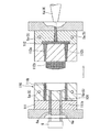
次に、金型交換工程として、金型110において、第一の可動型112を第二の可動型113に交換した。すなわち、図3に示すように、まず金型交換手段7を構成する押圧部材6のピン6aを固定型111の貫通孔111cに挿入して第一の可動型112のコア112bを押圧する。そして、図4に示すように、押圧部材6によってコア112bが押圧された状態で移動手段3によって固定型111に対して第一の可動型112を後退させることで、コア112bと成形されたレンズ枠101とは離間して、固定型111に対して第一の可動型112が離脱した状態となる。次に、移動手段3によって配列方向Yに可動部2bを移動させて、第二の可動型113が固定型111と対向するように配置させる。そして、可動部2bを固定部2aに向かって進出させることで、図5に示すように、コア113bが金型110のキャビティ111b内に挿入され、固定型111と第二の可動型113とが組み付けられた状態となり、コア113b及び先に成形されたレンズ枠101によりキャビティ111bの形状がレンズ102と対応する形状となる。
Next, as a mold replacement step, the first
次に、高分子材料射出工程として、第二の部分となるレンズ102を形成する高分子材料の射出を行う。射出手段4において、上記高分子材料を選択し、該高分子材料の溶融温度以上熱分解温度以下となるように設定する。そして、図6に示すように、射出手段4は、ノズル4aから第二の可動型113に形成されたランナ113cに高分子材料を射出する。そして、金属ガラス冷却工程において、金属ガラスの温度を高分子材料の熱分解温度以下となるように冷却しているので、射出された高分子材料は、熱分解してしまうことなくキャビティ111b内に射出されることとなる。なお、高分子材料の射出する量は、該高分子材料の比重と、第二の可動型113のランナ113c及びコア113b、並びに、固定型111のキャビティ111bの各体積とから算出される。
Next, as a polymer material injection step, a polymer material that forms the
次に、高分子材料冷却工程として、射出された高分子材料の冷却を行う。なお、高分子材料の冷却としては、冷却手段5によって行うものとしても良いし、自然法冷によって行うものとしても良い。最後に、金型取外し工程として、移動手段3によって固定型111に対して第二の可動型113を離脱させることで、金属ガラスで形成されたレンズ枠101と、高分子材料で形成されたレンズ102とで構成された一体成形品である図2に示す光学素子デバイス100が製造されることとなる。
Next, as the polymer material cooling step, the injected polymer material is cooled. The polymer material may be cooled by the cooling means 5 or by natural method cooling. Finally, as a mold removing step, the moving
以下に、上記成形方法によって具体的に光学素子デバイス100を製造した実施例について示す。本実施例では、レンズ枠101の材質をZr55Cu30Al10Ni5の4元系金属ガラス、レンズ102を形成する材質をポリカーボネートとして、上記成形方法により図2に示す光学素子デバイス100の製造を行った。なお、Zr55Cu30Al10Ni5の4元系金属ガラスは、融点が750℃、ガラス遷移温度が450℃、結晶化温度が490℃、臨界冷却速度は1℃/sである。また、ポリカーボネートの熱分解温度は大気雰囲気下において340℃である。
Hereinafter, examples in which the
まず、金型設定工程として、金型110の材質及び重量を決定し、金型110本体部分の形状を決定した。金型110としては、炭素鋼を使用した。そして、該炭素鋼の比熱461J/kg・℃、及び、Zr55Cu30Al10Ni5の4元系金属ガラスの比熱265.8J/kg・℃、並びに、成形する光学素子デバイス100の形状、及び、以下に示す金属ガラス射出工程及び金属ガラス冷却工程の諸条件から、金型110の本体部分の形状を決定した。
First, as the mold setting step, the material and weight of the
次に、金属ガラス射出工程を行った。Zr55Cu30Al10Ni5の4元系金属ガラスの温度を融点以上の950℃に設定し、該金属ガラスを注入圧力10MPaで金型110のキャビティ111b内に射出した。射出された直後のキャビティ111b内の金属ガラスの温度は、758℃と融点以上であった。そして、金属ガラス冷却工程として、冷却手段5によりキャビティ111b内の758℃の金属ガラスを、冷却速度を臨界冷却速度の1℃/Sとして冷却することで、ポリカーボネートの熱分解温度となる340℃まで冷却することができ、レンズ枠101を成形することができた。
Next, a metal glass injection process was performed. The temperature of the quaternary metallic glass of Zr 55 Cu 30 Al 10 Ni 5 was set to 950 ° C. above the melting point, and the metallic glass was injected into the
次に、金型交換工程として、第一の可動型112と第二の可動型113とを交換した後に、高分子材料射出工程として、ポリカーボネートを300℃まで加熱溶融して射出した。その後、高分子材料冷却工程として、ポリカーボネートが60℃となるまで保圧をかけながら更に金型を冷却させることで、レンズ102を成形することができた。そして、最後に金型取外し工程として固定型111から第二の可動型113を離脱することで、Zr55Cu30Al10Ni5の4元系金属ガラスからなるレンズ枠101と、ポリカーボネートからなるレンズ102とで構成された光学素子デバイス100を製造することができた。
Next, after exchanging the first
なお、本実施例の比較例として、金属ガラス冷却工程における冷却速度を臨界冷却速度未満の0.05℃/sとして、光学素子デバイス100の製造を行った。この場合、レンズ枠101には金属ガラスが形成されず、高精度に金型を転写することができなかった。また、これにより後工程の高分子材料射出工程及び高分子冷却工程においてもレンズ102を高精度に成形することができなかった。また、キャビティ111b内の金属ガラスの温度が450℃の時点でポリカーボネートを射出して成形したところ、本来透明であるべきポリカーボネートが熱分解によって茶褐色に濁った状態で成形されており、本来の高分子が持つ特性を発揮することが出来ないことが分かった。
As a comparative example of this example, the
以上のように、本実施形態の成形装置1及び成形方法によれば、金属ガラス冷却工程で冷却手段5によって金属ガラスを臨界冷却速度以上の冷却速度で高分子材料の熱分解温度以下となるまで冷却していることで、第二の部分となるレンズ102を形成する高分子材料を熱の影響を受けることなく射出成形することができる。そして、予め第一の部分となるレンズ枠101を金属ガラスで形成しておくことで、レンズ枠101と対応させてレンズ102を精度良く成形することができる。
As mentioned above, according to the shaping | molding apparatus 1 and shaping | molding method of this embodiment, until it becomes below the thermal decomposition temperature of a polymeric material with the cooling rate more than a critical cooling rate by the cooling means 5 by the cooling means 5 in a metal glass cooling process. By cooling, the polymer material forming the
(第2の実施形態)
次に、本発明の第2の実施形態について説明する。なお、本実施形態は、成形する工程の一部が異なるものであり、成形装置としては基本的に同様のものであるので図1に基づいて説明を行う。
(Second Embodiment)
Next, a second embodiment of the present invention will be described. In the present embodiment, a part of the molding process is different, and the molding apparatus is basically the same, so that description will be made based on FIG.
本実施形態の成形方法では、第1の実施形態と比較して、金属ガラス射出工程を行う前に金型冷却工程として、冷却手段5により金型110を予め冷却しておく点で大きく異なっている。そして、金属ガラス射出工程では、予め冷却された金型110のキャビティ111b内に金属ガラスを射出することで、金属ガラスは金型110との温度差により冷却されることとなり、すなわち、金属ガラス射出工程と同時に金属ガラス冷却工程が行われることとなる。ここで、金属ガラス冷却工程における金属ガラスの冷却速度は、金型110の熱容量及び金属ガラス射出工程開始時の金型110の温度に依存している。このため、金型設定工程においては、冷却速度が金属ガラスの臨界冷却速度以上となるように、金型110の熱容量及び金型110の金属ガラス射出工程開始時の温度を決定し、これに基づいて、金型110の材質及び重量を決定し、また、金型冷却工程における金型の目標冷却温度を決定する。
The molding method of the present embodiment is significantly different from the first embodiment in that the
以下に、上記成形方法によって具体的に光学素子デバイス100を製造した実施例について示す。本実施例でも同様に、レンズ枠101の材質をZr55Cu30Al10Ni5の4元系金属ガラス、レンズ102を形成する材質をポリカーボネートとして、上記成形方法により図2に示す光学素子デバイス100の製造を行った。
Hereinafter, examples in which the
まず、金型設定工程として、金型110の材質及び重量を決定し、金型110本体部分の形状を決定した。金型110としては、同様に炭素鋼を使用した。そして、該炭素鋼の比熱461J/kg・℃、比重7.8g/cm3及び、Zr55Cu30Al10Ni5の4元系金属ガラスの比熱265.8J/kg・℃、比重6.7g/cm3、並びに、成形する光学素子デバイス100の形状、及び、以下に示す金型冷却工程及び金属ガラス射出工程の諸条件から、金型110の本体部分の形状を決定した。また、次の金型冷却工程における目標冷却温度を25℃に決定した。そして、金型冷却工程では、冷却手段5において図示しない供給部から冷却配管5aに供給される冷却水により金型の温度を目標冷却温度の25℃となるように冷却した。
First, as the mold setting step, the material and weight of the
次に、金属ガラス射出工程及び金属ガラス冷却工程を行った。Zr55Cu30Al10Ni5の4元系金属ガラスの温度を融点以上の950℃に設定し、該金属ガラスを注入圧力10MPaで金型110のキャビティ111b内に射出した。この際、本実施例においては、冷却手段5による冷却を継続して行うものとし、冷却水を流量3L/minで循環させた。この結果、射出後の金属ガラスは、ポリカーボネートの熱分解温度340℃までの温度差130℃を26秒、冷却速度を5℃/s(臨界冷却速度1℃/s)として冷却することができた。以下、実施例1と同様に、金型交換工程、高分子材料射出工程、高分子材料冷却工程、並びに、金型取外し工程を実施することで、光学素子デバイス100を得ることができた。
Next, a metal glass injection process and a metal glass cooling process were performed. The temperature of the quaternary metallic glass of Zr 55 Cu 30 Al 10 Ni 5 was set to 950 ° C. above the melting point, and the metallic glass was injected into the
以上のように、本実施形態の成形方法によれば、第1の実施形態同様に、金属ガラス冷却工程で金属ガラスを高分子材料の熱分解温度以下となるまで冷却していることで、第二の部分となるレンズ102を形成する高分子材料を熱の影響を受けることなく射出成形することができる。そして、予め第一の部分となるレンズ枠101を金属ガラスで形成しておくことで、レンズ枠101と対応させてレンズ102を精度良く成形することができる。さらに、本実施形態では、金型冷却工程として、予め金型を冷却することにより金属ガラスを冷却することで、射出するのと同時に正確な温度制御のもと金属ガラスを冷却することができる。なお、上記実施例2では、金属ガラスを射出しながらも冷却手段5による冷却水の供給を行っているが、冷却水の供給を行わず、予め冷却された金型と金属ガラスとの温度差のみをもって金属ガラスを冷却するものとしても良い。
As described above, according to the molding method of the present embodiment, as in the first embodiment, the metal glass is cooled in the metal glass cooling step until the temperature is lower than the thermal decomposition temperature of the polymer material. The polymer material forming the
以上、本発明の実施形態について図面を参照して詳述したが、具体的な構成はこの実施形態に限られるものではなく、本発明の要旨を逸脱しない範囲の設計変更等も含まれる。
例えば、上記実施形態では、溶融状態の金属ガラスを、金属ガラス合金を加熱溶融することによって得ているが、金属ガラスを構成する各元素を溶融状態にした後、金属ガラスとなる組成で混合することによって作製しても良い。
As mentioned above, although embodiment of this invention was explained in full detail with reference to drawings, the concrete structure is not restricted to this embodiment, The design change etc. of the range which does not deviate from the summary of this invention are included.
For example, in the above-described embodiment, the molten metallic glass is obtained by heating and melting a metallic glass alloy. After each element constituting the metallic glass is brought into a molten state, it is mixed with a composition that becomes the metallic glass. You may produce by.
なお、上記各実施形態においては、金属ガラスと高分子材料との一体成形品として光学素子デバイスを例に挙げたがこれに限るものでは無く、様々な成形品に上記成形装置及び成形方法を適用可能である。また、金属ガラスとしては、Zr−Cu−Al−Niの4元系金属ガラスを例に挙げたがこれに限るものでは無く、様々な金属ガラス材料を使用可能であり、例えば、Pd−Cu−Ni−Pの4元系金属ガラス(臨界冷却速度0.1℃/s)やZr50−Cu40−Al10の3元系金属ガラス(ガラス遷移温度:433℃、結晶化温度:519℃、融点:819℃)などがある。同様に、高分子材料としてはポリカーボネートを例に挙げたがこれに限るものでは無く、様々な高分子材料を使用可能であり、例えば、メタクリル酸メチル樹脂(PMMA:熱分解温度(大気雰囲気下)330℃)やポリ塩化ビニル(PVC:熱分解温度(窒素雰囲気下)286℃)、シクロオレフィン樹脂(熱分解温度(大気雰囲気下)400℃)などがある。 In each of the above embodiments, the optical element device is exemplified as an integrally molded product of metal glass and polymer material, but the present invention is not limited to this, and the molding apparatus and the molding method are applied to various molded products. Is possible. In addition, as the metallic glass, Zr—Cu—Al—Ni quaternary metallic glass is given as an example. However, the metallic glass is not limited to this, and various metallic glass materials can be used. For example, Pd—Cu— Ni—P quaternary metallic glass (critical cooling rate 0.1 ° C./s) and Zr 50 —Cu 40 —Al 10 ternary metallic glass (glass transition temperature: 433 ° C., crystallization temperature: 519 ° C., Melting point: 819 ° C.). Similarly, polycarbonate has been exemplified as the polymer material, but is not limited thereto, and various polymer materials can be used. For example, methyl methacrylate resin (PMMA: thermal decomposition temperature (in the atmosphere)) 330 ° C.), polyvinyl chloride (PVC: thermal decomposition temperature (under nitrogen atmosphere) 286 ° C.), cycloolefin resin (thermal decomposition temperature (under atmospheric atmosphere) 400 ° C.), and the like.
1 成形装置
2 金型設置部
4 射出手段
5 冷却手段
7 金型交換手段
DESCRIPTION OF SYMBOLS 1
Claims (5)
少なくとも一部が交換可能に構成され前記第一の部分と対応する形状に形成された金型のキャビティ内に、前記金属ガラスを融点以上に加熱した状態で射出する金属ガラス射出工程と、
前記金型の前記キャビティ内に射出された前記金属ガラスを、臨界冷却速度以上の冷却速度で、前記高分子材料の熱分解温度以下となるまで冷却する金属ガラス冷却工程と、
前記金型の少なくとも一部を交換して、キャビティを前記第二の部分と対応する形状に形成する金型交換工程と、
前記第二の部分と対応する形状に形成された前記金型の前記キャビティ内に、前記高分子材料を射出する高分子材料射出工程とを備えることを特徴とする金属ガラスと高分子材料との一体成形品の成形方法。 A method for forming an integrally molded product of a metal glass and a polymer material, which is composed of a first portion formed of a metal glass and a second portion formed of a polymer material,
A metal glass injection step of injecting the metal glass in a state where the metal glass is heated to a melting point or higher in a mold cavity formed in a shape corresponding to the first part and configured to be at least partially exchangeable;
A metal glass cooling step for cooling the metal glass injected into the cavity of the mold at a cooling rate equal to or higher than a critical cooling rate until the temperature is equal to or lower than a thermal decomposition temperature of the polymer material;
A mold exchanging step of exchanging at least a part of the mold and forming a cavity in a shape corresponding to the second part;
A metal material injection step of injecting the polymer material into the cavity of the mold formed in a shape corresponding to the second portion; Molding method for integrally molded products.
前記金属ガラス射出工程の前に、前記金型を所定温度まで冷却する金型冷却工程を備え、
前記金属ガラス冷却工程は、前記金型冷却工程で冷却された前記金型と、該金型の前記キャビティ内に射出された前記金属ガラスとの温度差によって行われることを特徴とする金属ガラスと高分子材料の一体成形品の成形方法。 In the shaping | molding method of the integrally molded product of the metal glass and polymer material of Claim 1,
Before the metal glass injection step, comprising a mold cooling step for cooling the mold to a predetermined temperature,
The metal glass cooling step is performed by a temperature difference between the mold cooled in the mold cooling step and the metal glass injected into the cavity of the mold, and A method for forming an integrally molded product of a polymer material.
前記金属ガラス射出工程で射出される金属ガラスの質量、温度及び比熱に基づいて、前記金属ガラス冷却工程で前記金属ガラスを臨界冷却速度以上の冷却速度で冷却するのに必要な前記金型の熱容量を算出し、該熱容量に応じた材質及び質量に前記金型を設定する金型設定工程を備えることを特徴とする金属ガラスと高分子材料との一体成形品の成形方法。 In the shaping | molding method of the integrally molded product of the metal glass and polymer material of Claim 1 or Claim 2,
Based on the mass, temperature, and specific heat of the metal glass injected in the metal glass injection process, the heat capacity of the mold required to cool the metal glass at a cooling rate higher than the critical cooling rate in the metal glass cooling process. And a mold setting step of setting the mold to a material and mass corresponding to the heat capacity, and a method for forming an integrally molded product of metal glass and polymer material.
少なくとも一部を交換することで、キャビティを前記第一の部分と前記第二の部分とのそれぞれに対応した形状に切換可能な金型が設置される金型設置部と、
該金型設置部に設置された前記金型の少なくとも一部を交換可能な金型交換手段と、
前記金型設置部に設置された前記金型の前記キャビティ内に前記金属ガラスと高分子材料とのそれぞれを射出する射出手段と、
前記金型の前記キャビティ内に射出された前記金属ガラスを臨界冷却速度以上の冷却速度で所定温度まで冷却可能な冷却手段とを備えることを特徴とする金属ガラスと高分子材料との一体成形品用成形装置。 A molding apparatus for an integrally molded product of a metal glass and a polymer material composed of a first portion made of metal glass and a second portion made of polymer material,
A mold installation part in which a mold capable of switching the cavity to a shape corresponding to each of the first part and the second part is installed by exchanging at least a part;
A mold exchanging means capable of exchanging at least a part of the mold installed in the mold installing section;
Injection means for injecting each of the metallic glass and the polymer material into the cavity of the mold installed in the mold installation unit;
A cooling unit capable of cooling the metallic glass injected into the cavity of the mold to a predetermined temperature at a cooling rate equal to or higher than a critical cooling rate. Molding equipment.
前記冷却手段は、前記金属ガラスを射出する前の前記金型を冷却し、該金型の前記キャビティ内に前記射出手段によって前記金属ガラスを射出することで、該金属ガラスを臨界冷却速度以上の冷却速度で冷却させることを特徴とする金属ガラスと高分子材料との一体成形品用成形装置。 A molding apparatus for an integrally molded product of the metallic glass and polymer material according to claim 4,
The cooling means cools the mold before injecting the metal glass, and injects the metal glass into the cavity of the mold by the injection means, thereby causing the metal glass to exceed a critical cooling rate. A molding apparatus for an integrally molded product of metallic glass and polymer material, characterized by cooling at a cooling rate.
Priority Applications (1)
| Application Number | Priority Date | Filing Date | Title |
|---|---|---|---|
| JP2009058467A JP5259461B2 (en) | 2009-03-11 | 2009-03-11 | Method of forming integrally molded product of metallic glass and polymer material, and molding device for integrally molded product |
Applications Claiming Priority (1)
| Application Number | Priority Date | Filing Date | Title |
|---|---|---|---|
| JP2009058467A JP5259461B2 (en) | 2009-03-11 | 2009-03-11 | Method of forming integrally molded product of metallic glass and polymer material, and molding device for integrally molded product |
Publications (2)
| Publication Number | Publication Date |
|---|---|
| JP2010208223A JP2010208223A (en) | 2010-09-24 |
| JP5259461B2 true JP5259461B2 (en) | 2013-08-07 |
Family
ID=42968930
Family Applications (1)
| Application Number | Title | Priority Date | Filing Date |
|---|---|---|---|
| JP2009058467A Expired - Fee Related JP5259461B2 (en) | 2009-03-11 | 2009-03-11 | Method of forming integrally molded product of metallic glass and polymer material, and molding device for integrally molded product |
Country Status (1)
| Country | Link |
|---|---|
| JP (1) | JP5259461B2 (en) |
Families Citing this family (9)
| Publication number | Priority date | Publication date | Assignee | Title |
|---|---|---|---|---|
| DE102011101956A1 (en) * | 2011-05-19 | 2012-11-22 | Gebr. Krallmann Gmbh | Method for injection-molding multi-component e.g. switch used in e.g. electrical industry, involves injection-molding a metal component onto base portion |
| US10197335B2 (en) * | 2012-10-15 | 2019-02-05 | Apple Inc. | Inline melt control via RF power |
| JP5993898B2 (en) * | 2013-07-11 | 2016-09-14 | クルーシブル インテレクチュアル プロパティ エルエルシーCrucible Intellectual Property Llc | Unevenly spaced induction coils for confinement of molten alloy |
| US9873151B2 (en) | 2014-09-26 | 2018-01-23 | Crucible Intellectual Property, Llc | Horizontal skull melt shot sleeve |
| JP2016210069A (en) * | 2015-05-07 | 2016-12-15 | 日本フローセル製造株式会社 | Method for manufacturing thermoplastic resin molded product by injection molding without creating sink mark or deformation on surface of molded product |
| FR3058146B1 (en) * | 2016-10-28 | 2020-07-17 | Hutchinson | PROCESS FOR DEGRADATION OF A POLY (ALCENE CARBONATE), USES FOR PREPARING A LITHIUM-ION BATTERY ELECTRODE AND SINTERING CERAMICS |
| CN109434078A (en) * | 2018-10-29 | 2019-03-08 | 东莞市坚野材料科技有限公司 | Composite component containing amorphous alloy and preparation method thereof |
| EP3871804B1 (en) * | 2020-02-25 | 2024-11-06 | Heraeus Amloy Technologies GmbH | Method for adapting a component description of a workpiece to be manufactured with amorphous properties |
| CN111792619B (en) * | 2020-07-17 | 2024-05-17 | 中国科学技术大学 | Method for continuously manufacturing micro-nano structure on glass surface in batch |
Family Cites Families (2)
| Publication number | Priority date | Publication date | Assignee | Title |
|---|---|---|---|---|
| JP2005289757A (en) * | 2004-04-01 | 2005-10-20 | Olympus Corp | Method of forecasting forming behavior of optical device, forming method and forming die |
| JP2006252854A (en) * | 2005-03-09 | 2006-09-21 | Dainatsukusu:Kk | Method for producing metal glass separator |
-
2009
- 2009-03-11 JP JP2009058467A patent/JP5259461B2/en not_active Expired - Fee Related
Also Published As
| Publication number | Publication date |
|---|---|
| JP2010208223A (en) | 2010-09-24 |
Similar Documents
| Publication | Publication Date | Title |
|---|---|---|
| JP5259461B2 (en) | Method of forming integrally molded product of metallic glass and polymer material, and molding device for integrally molded product | |
| CN102582081B (en) | For the manufacture of the method for moulded product | |
| KR20040086463A (en) | Method for expansion injection molding | |
| US20090263533A1 (en) | Method of molding a hollow molded article, hollow molded article, and apparatus for manufacturing the same | |
| JP4444982B2 (en) | Manufacturing method of molded body | |
| KR20200031877A (en) | Cassette type injection molding apparatus for manufacturing of silicone products | |
| JPH06315961A (en) | Method and apparatus for injection molding without causing visible sink mark on product | |
| JP4674241B2 (en) | Method for heating molding mold and method for producing resin molded product | |
| US20200086537A1 (en) | Injection mold for producing injection-molded components, and method for producing injection-molded components | |
| US8092208B2 (en) | Gas-assisted mold surface heating system | |
| JP2009202549A (en) | Production process of resin molded article | |
| JP5059973B2 (en) | Injection molding method and apparatus for injection product having hydrophobic pattern | |
| JPWO2020017579A1 (en) | Molds for injection molding and manufacturing methods for molded products | |
| JP2009090558A (en) | Injection mold, method for manufacturing injection molded product, and injection molded product | |
| JP5200835B2 (en) | Resin mold and injection molding machine | |
| JP2008230005A (en) | Plastic lens molding method and lens preform | |
| KR100549394B1 (en) | Runner device for in-mold molding | |
| JPH08127032A (en) | Method for manufacturing plastic molded products | |
| JP2013082205A (en) | Thermoplastic resin molded article manufacturing method | |
| JP2002096351A (en) | In-mold coating method | |
| JP2010149421A (en) | Resin molding apparatus and molding machine | |
| JP2008284704A (en) | Mold and method of manufacturing optical element | |
| JPWO2013146871A1 (en) | Method and apparatus for manufacturing thermoplastic resin product | |
| JP2807980B2 (en) | Manufacturing method of hollow injection molded products | |
| JP2017035821A (en) | Injection molding machine and injection molding method |
Legal Events
| Date | Code | Title | Description |
|---|---|---|---|
| A621 | Written request for application examination |
Free format text: JAPANESE INTERMEDIATE CODE: A621 Effective date: 20120111 |
|
| A977 | Report on retrieval |
Free format text: JAPANESE INTERMEDIATE CODE: A971007 Effective date: 20130404 |
|
| TRDD | Decision of grant or rejection written | ||
| A01 | Written decision to grant a patent or to grant a registration (utility model) |
Free format text: JAPANESE INTERMEDIATE CODE: A01 Effective date: 20130409 |
|
| A61 | First payment of annual fees (during grant procedure) |
Free format text: JAPANESE INTERMEDIATE CODE: A61 Effective date: 20130424 |
|
| FPAY | Renewal fee payment (event date is renewal date of database) |
Free format text: PAYMENT UNTIL: 20160502 Year of fee payment: 3 |
|
| R151 | Written notification of patent or utility model registration |
Ref document number: 5259461 Country of ref document: JP Free format text: JAPANESE INTERMEDIATE CODE: R151 |
|
| S531 | Written request for registration of change of domicile |
Free format text: JAPANESE INTERMEDIATE CODE: R313531 |
|
| R350 | Written notification of registration of transfer |
Free format text: JAPANESE INTERMEDIATE CODE: R350 |
|
| LAPS | Cancellation because of no payment of annual fees |