JP5259290B2 - Container pressurizer - Google Patents

Container pressurizer Download PDF

Info

Publication number
JP5259290B2
JP5259290B2 JP2008196094A JP2008196094A JP5259290B2 JP 5259290 B2 JP5259290 B2 JP 5259290B2 JP 2008196094 A JP2008196094 A JP 2008196094A JP 2008196094 A JP2008196094 A JP 2008196094A JP 5259290 B2 JP5259290 B2 JP 5259290B2
Authority
JP
Japan
Prior art keywords
air supply
container
air
chamber
supply nozzle
Prior art date
Legal status (The legal status is an assumption and is not a legal conclusion. Google has not performed a legal analysis and makes no representation as to the accuracy of the status listed.)
Active
Application number
JP2008196094A
Other languages
Japanese (ja)
Other versions
JP2010030645A (en
Inventor
修之 岩沢
時夫 高橋
隆裕 山岸
崇夫 片山
暢 山下
周太 伊東
雅敏 高木
幸伸 西納
竜弘 中田
利彦 荒井
Current Assignee (The listed assignees may be inaccurate. Google has not performed a legal analysis and makes no representation or warranty as to the accuracy of the list.)
Dai Nippon Printing Co Ltd
Suntory Holdings Ltd
Shibuya Corp
Original Assignee
Dai Nippon Printing Co Ltd
Suntory Holdings Ltd
Shibuya Corp
Priority date (The priority date is an assumption and is not a legal conclusion. Google has not performed a legal analysis and makes no representation as to the accuracy of the date listed.)
Filing date
Publication date
Application filed by Dai Nippon Printing Co Ltd, Suntory Holdings Ltd, Shibuya Corp filed Critical Dai Nippon Printing Co Ltd
Priority to JP2008196094A priority Critical patent/JP5259290B2/en
Publication of JP2010030645A publication Critical patent/JP2010030645A/en
Application granted granted Critical
Publication of JP5259290B2 publication Critical patent/JP5259290B2/en
Active legal-status Critical Current
Anticipated expiration legal-status Critical

Links

Images

Landscapes

  • Basic Packing Technique (AREA)
  • Filling Of Jars Or Cans And Processes For Cleaning And Sealing Jars (AREA)

Description

本発明は容器加圧装置に係り、特に、軽量の樹脂製容器をエアコンベヤによって搬送する際に変形した場合等に、この容器内にエアを吹き込んで加圧することによって元の形状に復帰させる容器加圧装置に関するものである。   The present invention relates to a container pressurizing device, and in particular, when a lightweight resin container is deformed when transported by an air conveyor, the container is returned to its original shape by blowing air into the container and pressurizing it. The present invention relates to a pressure device.

近年、ペットボトル等の樹脂製容器の軽量化に伴い、次第に容器の肉厚が薄くなっており、容器自体の強度が弱くなってきている。このような樹脂製容器は、通常、ボトル成型機によって成型された後、エアコンベヤによって搬送されて、リンサやフィラ、キャッパ等の各種容器処理機に順次送られ、各処理機において所定の処理が行われるが、エアコンベヤでの搬送中においては、容器は吊り下げ状態にて前後する容器が当接しながらエア噴射の推進力で前進されるようになっており、容器処理機への導入部等の減速箇所では順次前方の容器を押圧するため、特に肉厚の薄い容器では、強度不足から容器が変形してしまう場合があった。このような変形した容器は、見栄えが悪くなるばかりでなく後に液体を充填する際に、溢れたり容量不足を生ずるという問題がある。そこで、変形した容器を修復する装置がすでに提案されている(例えば、特許文献1または特許文献2参照)。   In recent years, with the reduction in weight of plastic containers such as plastic bottles, the thickness of the containers has gradually decreased, and the strength of the containers themselves has become weaker. Such a resin container is usually molded by a bottle molding machine, then conveyed by an air conveyor, and sequentially sent to various container processing machines such as a rinser, a filler, and a capper, and predetermined processing is performed in each processing machine. While being carried by the air conveyor, the container is moved forward by the propelling force of the air jet while the containers moving in the suspended state come into contact with each other. Since the forward containers are sequentially pressed at the decelerating portion, the container may be deformed due to insufficient strength, particularly in a thin container. Such a deformed container is not only poor in appearance but also has a problem that it overflows and lacks capacity when it is filled with liquid later. Therefore, an apparatus for repairing a deformed container has already been proposed (see, for example, Patent Document 1 or Patent Document 2).

特許文献1に記載された変形プラスチックボトルの修正方法では、プラスチックボトルの内部にノズル装置によって空気を噴射させ、このボトルを空気洗浄するボトル洗浄装置において、変形プラスチックボトルを修正するようになっており、ノズル装置によりプラスチックボトルを密閉し、それより噴射される空気でプラスチックボトルを加圧する工程を設けたものである。   In the method for correcting a deformed plastic bottle described in Patent Document 1, the deformed plastic bottle is corrected in a bottle cleaning device in which air is injected into the inside of the plastic bottle by a nozzle device, and the bottle is cleaned with air. The plastic bottle is hermetically sealed by the nozzle device, and the process of pressurizing the plastic bottle with the air jetted therefrom is provided.

また、特許文献2に記載された脆弱容器の充填前処理方法は、脆弱容器の開口部を密封状態に保つ密封工程と、密封工程で密封された脆弱容器内に空気を送給し、脆弱容器を大気圧以上に加圧する加圧工程を備えており、前記加工工程にて脆弱容器の内圧を上昇させることにより、脆弱容器の潰れおよび凹みを除去するようにしている。
特開平1−281922号公報(第2−3頁、図3) 特開平11−11588号公報(第3−5頁、図3)
Moreover, the pre-filling processing method for a fragile container described in Patent Document 2 includes a sealing process for keeping the opening of the fragile container in a sealed state, and air is fed into the fragile container sealed in the sealing process. A pressurizing step of pressurizing the fragile container to an atmospheric pressure or higher is provided, and the internal pressure of the fragile container is increased in the processing step to remove the crushed and dents of the fragile container.
JP-A-1-281922 (page 2-3, FIG. 3) Japanese Patent Laid-Open No. 11-11588 (page 3-5, FIG. 3)

前述のように容器内にエアを吹き込んで加圧することによって変形した容器を復元する装置を、高い清浄度に維持された雰囲気内で殺菌もしくは滅菌状態の容器に内容物を充填する、アセプティック充填ラインを構成するアセプティックチャンバ内に設置した場合には、チャンバ内は容器滅菌のための滅菌剤が昇温されて噴霧され、また、容器洗浄のために温水が噴射されているために、外部雰囲気よりも高温多湿な環境にあり、容器内にエアを吹き込むための配管やノズルには、チャンバ内の温度と内部を流通している常温(外部雰囲気温度)のエアとの温度差から表面に結露が生じてしまう。結露が生じると、滴が落下して容器の内外面に付着してしまう場合があるが、このように滴が付着した場合には、付着した部分としない部分とで滅菌効果にバラツキが生じてしまい滅菌ムラとなってしまう。そこで、アセプティックチャンバ内に、前記のようにエアを容器内に吹き込んで復元する装置を設置する場合には、エアの供給管やエア供給ノズルの結露を防止する対策を講ずる必要がある。本発明は、容器内を加圧して変形を復元する装置をアセプティックチャンバ内に設置した場合に、結露の発生を防止することができる容器加圧装置を提供することを目的とするものである。   Aseptic filling line that fills sterilized or sterilized containers with a device that restores a deformed container by blowing and pressurizing air into the container as described above in an atmosphere maintained at high cleanliness. When the sterilizing agent for the container sterilization is heated and sprayed, and the hot water is sprayed for cleaning the container, the chamber is exposed to the external atmosphere. In the high temperature and humidity environment, the pipes and nozzles for blowing air into the container have dew condensation on the surface due to the temperature difference between the temperature in the chamber and the air at normal temperature (external ambient temperature) circulating inside. It will occur. If dew condensation occurs, the drops may drop and adhere to the inner and outer surfaces of the container, but in this way, if the drops adhere, the sterilization effect will vary between the attached and non-attached parts. This will result in uneven sterilization. Therefore, when an apparatus for restoring air by blowing it into the container as described above is installed in the aseptic chamber, it is necessary to take measures to prevent condensation of the air supply pipe and the air supply nozzle. An object of the present invention is to provide a container pressurizing apparatus capable of preventing the occurrence of condensation when an apparatus for pressurizing the inside of a container to restore deformation is installed in an aseptic chamber.

さらに、前記特許文献1の構成では、ボトルテーブル7に載置されたプラスチックボトル2の開口部40に、ノズル装置35を下降させ突起部材39を押圧させて開口部40を密閉するようにしている。また、特許文献2の構成では、容器搬送板32に載置された容器Bの開口部B1にノズル装置34を下降させて装着部38が密嵌するようになっている。前記各特許文献のボトルテーブル7や容器搬送板32に容器を載置した状態でノズルを下降させる構成では、潰れや凹みが激しい場合には口部が真上を向かず斜め方向を向き、上方開口部に対してノズルを正しく位置させることができない場合がある。これに対して、前記特許文献2では、薄肉の蛇腹構造をなすゴム製の密接部材38fを設けるようにしている。しかしながら、激しい凹みや潰れの発生頻度が低い場合にも同様に構成することは無駄であり、また、薄肉の蛇腹構造をなすゴム製の密接部材では耐久性が低く、さらに、蛇腹構造では洗浄性が悪くなるという問題がある。また、上端の口部を上方から押圧して密封する場合では、肉厚の薄い容器の場合は潰れるおそれがある。胴部に凹みが生じている容器ではさらに強度が低下しており、特に潰れ易いという問題がある。   Further, in the configuration of Patent Document 1, the nozzle device 35 is lowered and the protruding member 39 is pressed into the opening 40 of the plastic bottle 2 placed on the bottle table 7 to seal the opening 40. . Further, in the configuration of Patent Document 2, the mounting unit 38 is closely fitted by lowering the nozzle device 34 to the opening B1 of the container B placed on the container transport plate 32. In the configuration in which the nozzle is lowered in a state where the container is placed on the bottle table 7 or the container transport plate 32 of each of the above patent documents, the mouth portion does not face directly upward and faces in an oblique direction when the crushing or dent is severe, The nozzle may not be correctly positioned with respect to the opening. On the other hand, in Patent Document 2, a rubber close member 38f having a thin bellows structure is provided. However, it is useless to make the same structure even when the frequency of occurrence of severe dents and crushing is low, and the rubber close contact member forming a thin bellows structure is low in durability, and furthermore, the bellows structure is washable. There is a problem of getting worse. Moreover, in the case of sealing by pressing the upper end mouth portion from above, there is a risk of collapse in the case of a thin container. In a container in which a dent is generated in the body part, the strength is further lowered, and there is a problem that it is particularly easily crushed.

本発明は、前記課題を解決するためになされたもので、容器の首部を支持した状態で給気ノズルを口部に対する吹き込み位置に位置させるようにしたことにより、胴部が激しく潰れている場合でも、首部を支持した状態では口部が斜め上方を向くことはなく、常に確実に口部に対して給気ノズルを位置させることができる容器加圧装置を提供することができる。また、口部を上方から強く押圧して密封する場合にも薄肉の胴部が潰れてしまうおそれのない容器加圧装置を提供するものである。   The present invention has been made in order to solve the above-described problem, and the body portion is severely crushed by positioning the air supply nozzle at the blowing position with respect to the mouth portion while supporting the neck portion of the container. However, it is possible to provide a container pressurizing apparatus in which the mouth portion does not face obliquely upward in a state where the neck portion is supported, and the air supply nozzle can always be reliably positioned with respect to the mouth portion. Further, the present invention provides a container pressurizing device that does not cause the thin-walled body portion to be crushed even when the mouth portion is strongly pressed from above and sealed.

請求項1に記載した発明は、気体が供給される給気管と、この給気管から供給される気体を吹き出す給気ノズルとを備え、給気ノズルから樹脂製容器内に気体を吹き込んで容器内部を加圧する容器加圧装置において、前記給気管および給気ノズルの結露を防止する結露防止手段を備えたことを特徴とするものである。   The invention described in claim 1 includes an air supply pipe to which a gas is supplied and an air supply nozzle for blowing out the gas supplied from the air supply pipe, and the gas is blown into the resin container from the air supply nozzle. In the container pressurizing apparatus for pressurizing the water, a dew condensation preventing means for preventing dew condensation on the air supply pipe and the air supply nozzle is provided.

また、請求項2に記載の発明は、前記結露防止手段として、前記給気管に供給される気体を加熱するヒータを設け、このヒータによって昇温させた気体を給気管へ供給し、給気ノズルから吹き出すことを特徴とするものである。   According to a second aspect of the present invention, there is provided a heater for heating the gas supplied to the air supply pipe as the dew condensation preventing means, and the gas heated by the heater is supplied to the air supply pipe. It is characterized by being blown out from.

さらに、請求項3に記載の発明は、前記給気ノズルに向けて無菌エアを吹き付ける噴射ノズルを設けたことを特徴とするものである。   Furthermore, the invention described in claim 3 is characterized in that an injection nozzle that blows aseptic air toward the air supply nozzle is provided.

請求項4に記載の発明は、前記給気ノズルを加温する加温手段を設け、加温することで給気ノズルの結露を防止するようにしたことを特徴とするものである。   The invention described in claim 4 is characterized in that a heating means for heating the air supply nozzle is provided, and the dew condensation of the air supply nozzle is prevented by heating.

請求項5に記載の発明は、前記ヒータによって昇温させた気体を、前記噴射ノズルから噴射することを特徴とするものである。   The invention according to claim 5 is characterized in that the gas heated by the heater is jetted from the jet nozzle.

請求項6に記載の発明は、前記給気管および給気ノズルを、内部雰囲気が外部よりも高温となるチャンバ内に設置して、チャンバ内で給気ノズルから樹脂製容器内に気体を吹き込んで容器内部を加圧することを特徴とするものである。   According to a sixth aspect of the present invention, the air supply pipe and the air supply nozzle are installed in a chamber in which the internal atmosphere is higher than the outside, and gas is blown into the resin container in the chamber from the air supply nozzle. The inside of the container is pressurized.

本発明の容器加圧装置は、アセプティックチャンバ内など外部雰囲気とは異なる環境に設置した場合でも、結露が生じることを確実に防止して、容器の滅菌ムラ等の発生を抑制することができる。また、容器の首部を支持することで、口部に対して給気ノズルを正しく位置させて加圧することができる。   Even when the container pressurizing apparatus of the present invention is installed in an environment different from the external atmosphere, such as in an aseptic chamber, it is possible to reliably prevent the occurrence of condensation and suppress the occurrence of uneven sterilization of the container. Further, by supporting the neck portion of the container, the air supply nozzle can be correctly positioned with respect to the mouth portion and pressurized.

気体が供給される給気管と、この給気管から供給された気体を吹き出す給気ノズルとを備えており、この給気ノズルから樹脂製容器内に気体を吹き込んで容器内部を加圧するものであり、さらに、給気管および給気ノズルの結露を防止する結露防止手段を設けたという構成により、給気管および給気ノズルの結露を防止するという目的を達成する。   It is equipped with an air supply pipe to which gas is supplied and an air supply nozzle that blows out the gas supplied from the air supply pipe, and the inside of the container is pressurized by blowing gas into the resin container from the air supply nozzle. Furthermore, the object of preventing dew condensation on the air supply pipe and the air supply nozzle is achieved by providing the dew condensation prevention means for preventing dew condensation on the air supply pipe and the air supply nozzle.

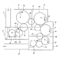
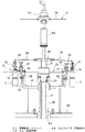
以下、図面に示す実施例により本発明を説明する。図1は本発明の一実施例に係る容器加圧装置を備えたアセプティック充填ラインの全体の構成を簡略化して示す平面図、図2は、容器加圧装置の縦断面図である。この実施例では、図示しないボトル成型機で成型された多数の樹脂製容器(この実施例ではペットボトル)2を、導入エアコンベヤ4によって連続的に搬送し、連続して配置された複数のチャンバからなるアセプティックチャンバ(以下、これら各チャンバを第1チャンバ6、第2チャンバ8、第3チャンバ10、第4チャンバ12および第5チャンバ14と呼ぶ)内に導入し、順次受け渡しを行いながら各チャンバ6、8、10、12、14内に設置された各処理機(この実施例では滅菌機、リンサ、フィラ、キャッパ)においてそれぞれ所定の処理を行った後、第5チャンバ14から排出側のエアコンベヤ16に引き渡して次の工程に送るようになっている。これらアセプティックチャンバ6、8、10、12、14は、全体としてはボトルを搬送するための開口を除いて外部雰囲気から遮断され、内部に無菌エアが吹き込まれて外部よりも陽圧に維持されている。また、これら各チャンバは、フィラを設置した第4チャンバ12が最も圧力が高く、次いでリンサを設置した第3チャンバ10とキャッパを設置した第5チャンバ14はこれよりも低く、滅菌機を設置した第2チャンバ8はさらに低く、導入部となる第1チャンバ6が最も低くなるように圧力状態が調整されている。   Hereinafter, the present invention will be described with reference to embodiments shown in the drawings. FIG. 1 is a plan view schematically showing the entire structure of an aseptic filling line equipped with a container pressurizing apparatus according to an embodiment of the present invention, and FIG. 2 is a longitudinal sectional view of the container pressurizing apparatus. In this embodiment, a plurality of resin containers (in this embodiment, PET bottles) 2 molded by a bottle molding machine (not shown) are continuously conveyed by an introduction air conveyor 4 and a plurality of chambers arranged in succession. Are introduced into the aseptic chamber (hereinafter referred to as the first chamber 6, the second chamber 8, the third chamber 10, the fourth chamber 12 and the fifth chamber 14), and each chamber is transferred while being sequentially transferred. After performing predetermined processing in each processing machine (in this embodiment, a sterilizer, a rinser, a filler, and a capper) installed in 6, 8, 10, 12, and 14, air from the fifth chamber 14 is discharged to the discharge side. It is transferred to the conveyor 16 and sent to the next process. These aseptic chambers 6, 8, 10, 12, and 14 are cut off from the outside atmosphere except for the opening for carrying the bottles as a whole, and sterilized air is blown into the interior to maintain a positive pressure from the outside. Yes. In each of these chambers, the pressure in the fourth chamber 12 in which the filler is installed is highest, the third chamber 10 in which the rinser is installed, and the fifth chamber 14 in which the capper is installed are lower than this, and a sterilizer is installed. The second chamber 8 is further lower, and the pressure state is adjusted so that the first chamber 6 serving as the introduction portion is lowest.

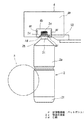
このアセプティック充填ラインで処理されるペットボトル2は、図3に示すように、胴部2aの上方に、上端に向かって次第に径が細くなるテーパ状の肩部2bを介して首部2cが設けられている。この首部2cの上端に口部2dが開口しており、また、首部2cの中間部の外周にフランジ2eが形成されている。首部2cは、肩部2b、胴部2aおよび底部2fよりも剛性が高く、後に説明するように、この首部2cに形成されたフランジ2eの上方または下方をグリッパによって把持することができる。   As shown in FIG. 3, the PET bottle 2 processed in this aseptic filling line is provided with a neck portion 2c above the trunk portion 2a via a tapered shoulder portion 2b whose diameter gradually decreases toward the upper end. ing. A mouth 2d is opened at the upper end of the neck 2c, and a flange 2e is formed on the outer periphery of the middle part of the neck 2c. The neck 2c has higher rigidity than the shoulder 2b, the trunk 2a, and the bottom 2f, and as described later, the upper or lower portion of the flange 2e formed on the neck 2c can be gripped by a gripper.

ペットボトル2を搬送する導入エアコンベヤ4は、外部から加圧したエアが送り込まれるエアダクト4aを有しており、このエアダクト4aの下部中央に、ペットボトル2の搬送路4bが形成されている。この搬送路4bの両側壁には、下流側へ向けて開口する多数のエア噴出口4cが設けられており、エアダクト4a内の加圧エアを噴射するようになっている。また、搬送路4bの下面側には、ペットボトル2の口部2dの外径よりもやや広く、しかも、フランジ2eの外径よりも狭い間隔で配置された一対の平行なガイドレール4dが設けられている。このエアコンベヤ4によって搬送されるペットボトル2は、フランジ2eの下面側を両側のガイドレール4dによって支持され、首部2cのフランジ2eよりも上方に、エア噴出口4cから噴射された加圧エアを吹き付けられて下流側に搬送される。このエアコンベヤ4の下流部の、第1導入ホイール18への受渡位置の手前にスクリュー5が設けられており、その外周に形成された螺旋溝によってペットボトル2の前後の間隔を第1導入ホイール18のグリッパ53の間隔に広げた後受け渡しを行うようになっている。   The introduction air conveyor 4 for conveying the PET bottle 2 has an air duct 4a into which pressurized air is sent from the outside, and a conveyance path 4b for the PET bottle 2 is formed at the lower center of the air duct 4a. A large number of air jets 4c that open toward the downstream side are provided on both side walls of the transport path 4b so as to inject pressurized air in the air duct 4a. In addition, a pair of parallel guide rails 4d are provided on the lower surface side of the transport path 4b. It has been. The PET bottle 2 conveyed by the air conveyor 4 is supported by the guide rails 4d on both sides of the flange 2e on the lower surface side, and receives the pressurized air injected from the air outlet 4c above the flange 2e of the neck 2c. Sprayed and conveyed downstream. The screw 5 is provided in the downstream part of the air conveyor 4 before the delivery position to the first introduction wheel 18, and the distance between the front and back of the PET bottle 2 is set by the spiral groove formed on the outer periphery of the screw 5. Delivery is performed after the gap between the 18 grippers 53 is widened.

導入エアコンベヤ4の下流端に接続された第1チャンバ6には、複数の導入ホイール(以下、第1導入ホイール18、第2導入ホイール20および第3導入ホイール22と呼ぶ)が配置されており、導入エアコンベヤ4によってエア搬送されてこの第1チャンバ6内に導入されたペットボトル2は、図示矢印A方向に搬送されて第1導入ホイール18、第2導入ホイール20および第3導入ホイール22に順次受け渡される。これら3つの導入ホイール18、20、22のうちの中間に位置する第2導入ホイール20に、後に説明する容器加圧装置が設けられている。   In the first chamber 6 connected to the downstream end of the introduction air conveyor 4, a plurality of introduction wheels (hereinafter referred to as a first introduction wheel 18, a second introduction wheel 20, and a third introduction wheel 22) are arranged. The PET bottle 2 that is air-conveyed by the introduction air conveyor 4 and introduced into the first chamber 6 is conveyed in the direction of the arrow A in the drawing, and the first introduction wheel 18, the second introduction wheel 20, and the third introduction wheel 22. Are sequentially delivered to. A container pressurizing device to be described later is provided on the second introduction wheel 20 located in the middle of the three introduction wheels 18, 20, and 22.

第3導入ホイール22は、第1チャンバ6と第2チャンバ8とを仕切る隔壁24に形成された開口(図示せず)内に配置されており、第1チャンバ6内の第2導入ホイール20から受け取ったペットボトル2を、回転搬送して第2チャンバ8内に導入する。第2チャンバ8内には、第1の処理機である滅菌機26が設置されており、第3導入ホイール24から引き渡されたペットボトル2を回転搬送する間に滅菌を行う。この実施例では、滅菌機26で、高温の滅菌ガスをペットボトル2の内外面に吹き付けて滅菌している。滅菌ガスとしては、120°C程度に加熱した無菌エアにミスト状の過酸化水素水等の滅菌作用を有する溶液を混入したものや、これら滅菌性、殺菌性の薬液を含む蒸気等が使用される。   The third introduction wheel 22 is disposed in an opening (not shown) formed in the partition wall 24 that partitions the first chamber 6 and the second chamber 8, and the third introduction wheel 22 extends from the second introduction wheel 20 in the first chamber 6. The received plastic bottle 2 is rotationally conveyed and introduced into the second chamber 8. A sterilizer 26, which is a first processing machine, is installed in the second chamber 8, and sterilization is performed while the PET bottle 2 delivered from the third introduction wheel 24 is rotated and conveyed. In this embodiment, the sterilizer 26 sterilizes by blowing hot sterilization gas onto the inner and outer surfaces of the PET bottle 2. As the sterilizing gas, sterilized air heated to about 120 ° C mixed with a solution having a sterilizing action such as mist-like hydrogen peroxide water, or steam containing these sterilizing and bactericidal chemicals is used. The

第2チャンバ8と第3チャンバ10とを仕切る隔壁27に形成された開口に中間ホイール(以下、第1中間ホイール28と呼ぶ)が配置されており、第2チャンバ8内の滅菌機26で滅菌されたペットボトル2は、この中間ホイール28を介して次の第3チャンバ10内に搬入される。この第3チャンバ10には第2の処理機であるリンサ30が設置されており、前記滅菌機26で滅菌されたペットボトル2の洗浄が行われる。この実施例では、リンサ30は70°C程度に加温された温水や滅菌または殺菌作用を有する薬液でペットボトル2の内外面を洗い流す。なお、滅菌機26およびリンサ30では、ペットボトル2の首部を支持して回転方向へ搬送しながら各処理を行う。   An intermediate wheel (hereinafter referred to as a first intermediate wheel 28) is disposed in an opening formed in a partition wall 27 that partitions the second chamber 8 and the third chamber 10, and is sterilized by a sterilizer 26 in the second chamber 8. The plastic bottle 2 is carried into the next third chamber 10 through the intermediate wheel 28. The third chamber 10 is provided with a rinser 30 as a second processing machine, and the plastic bottle 2 sterilized by the sterilizer 26 is washed. In this embodiment, the rinser 30 rinses the inner and outer surfaces of the PET bottle 2 with warm water heated to about 70 ° C. or a chemical solution having a sterilization or sterilization action. In addition, in the sterilizer 26 and the rinser 30, each process is performed while supporting the neck part of the PET bottle 2 and conveying in the rotation direction.

リンサ30での洗浄処理が済んだペットボトル2は、第3チャンバ10と第4チャンバ12との間の隔壁32に形成された開口内に配置されている第2中間ホイール34を介して、第4チャンバ12内に設置されている第3の処理機であるフィラ36に供給される。フィラ36内に供給されたペットボトル2は、回転搬送される間に液体が充填され、第4チャンバ12と第5チャンバ14との間を仕切る隔壁38に形成された開口部内に配置されている第3の中間ホイール40を介して、次の第5チャンバ14内に設置されている第4の処理機であるキャッパ42に引き渡される。フィラ36で液体が充填され、このキャッパ42でキャッピングが行われたペットボトル2は、第5チャンバ14内に配置されている第1排出ホイール44および第2排出ホイール46に順次受け渡された後、第5チャンバ14から排出されて前記排出エアコンベヤ16に引き渡されて次の工程に送られる。前記第2チャンバ8や第3チャンバ10は、滅菌機26やリンサ30を設けてあるので、チャンバ内が外部よりも高温で湿度も高くなっている。また、第1チャンバ6は、最も圧力が低いため、前記第2チャンバ8および第3チャンバ10からの雰囲気が流れ込み高温で多湿になっている。なお、これらアセプティックチャンバ内においては、ペットボトル2は首部2cのフランジ2eの上部と下部を交互に把持されて、複数の導入ホイール、各容器処理機とそれらの各中間ホイール、複数の排出ホイール間で順次受け渡されながら、首部2cを支持された状態で吊り下げ搬送されるようになっている。   The PET bottle 2 that has been cleaned by the rinser 30 passes through the second intermediate wheel 34 that is disposed in the opening formed in the partition wall 32 between the third chamber 10 and the fourth chamber 12. It is supplied to a filler 36 which is a third processing machine installed in the four chambers 12. The PET bottle 2 supplied into the filler 36 is filled with liquid while being rotated and conveyed, and is disposed in an opening formed in the partition wall 38 that partitions the fourth chamber 12 and the fifth chamber 14. It passes through the third intermediate wheel 40 to a capper 42 that is a fourth processing machine installed in the next fifth chamber 14. After the PET bottle 2 filled with the liquid by the filler 36 and capped by the capper 42 is sequentially delivered to the first discharge wheel 44 and the second discharge wheel 46 disposed in the fifth chamber 14. The air is discharged from the fifth chamber 14 and delivered to the discharge air conveyor 16 to be sent to the next step. Since the second chamber 8 and the third chamber 10 are provided with the sterilizer 26 and the rinser 30, the inside of the chamber is higher in temperature and humidity than the outside. In addition, since the pressure in the first chamber 6 is the lowest, the atmosphere from the second chamber 8 and the third chamber 10 flows in and is humid at a high temperature. In these aseptic chambers, the PET bottle 2 is alternately gripped by the upper and lower portions of the flange 2e of the neck portion 2c, and between the plurality of introduction wheels, the respective container processing machines, their respective intermediate wheels, and the plurality of discharge wheels. As the neck portion 2c is supported, it is conveyed while being sequentially delivered.

次に、図2により本発明の一実施例に係る凹みや潰れの生じた容器を復元する容器加圧装置の構成について説明する。容器加圧装置は前記第1チャンバ6内に配置されている第2導入ホイール20に設けられており、図1のB位置からC位置の間でペットボトル2内を加圧するようになっている。第1チャンバ6の底面6aに貫通孔6aaが形成され、この孔6aaを上下に貫通して直立した円筒部材48が固定されている。この固定円筒部材48の内部に、ベアリング50を介して回転軸52が回転自在に支持されている。回転軸52の上部外周に円板状の第2導入ホイール20が取り付けられており、回転軸52の回転によって一体的に回転する。この第2導入ホイール20の外周部に、容器の首部を支持する支持部材として円周方向等間隔で複数のグリッパ54が設けられている。この実施例のグリッパ54は、一対のグリップ部材をスプリング等の弾性部材によって互いに引き付けておき、それら両グリップ部材間にペットボトル2の首部2cを押し込むことにより挟持するようになっている。第1導入ホイール18のグリッパ53は、フランジ2eの上部を保持するようになっており、第2導入ホイール20のグリッパ54は、前記第1導入ホイール18のグリッパ53から、ペットボトル2を受け取ってそのフランジ2eの下部側を把持する。なお、グリッパ54は前記構成に限定されるものではなく、その他の構成のグリッパを用いるようにしても良く、首部2cを把持せずにフランジ2eの下面を支持して、ペットボトル2を単に吊り下げた状態で支持するものでも良い。   Next, the configuration of a container pressurizing apparatus for restoring a dent or a crushed container according to an embodiment of the present invention will be described with reference to FIG. The container pressurizing device is provided on the second introduction wheel 20 disposed in the first chamber 6 and pressurizes the inside of the plastic bottle 2 between the B position and the C position in FIG. . A through-hole 6aa is formed in the bottom surface 6a of the first chamber 6, and a cylindrical member 48 that is upright through the hole 6aa is fixed. A rotating shaft 52 is rotatably supported inside the fixed cylindrical member 48 via a bearing 50. A disc-shaped second introduction wheel 20 is attached to the outer periphery of the upper portion of the rotating shaft 52, and rotates integrally with the rotation of the rotating shaft 52. A plurality of grippers 54 are provided on the outer periphery of the second introduction wheel 20 at equal intervals in the circumferential direction as support members that support the neck of the container. The gripper 54 of this embodiment is configured such that a pair of grip members are attracted to each other by an elastic member such as a spring and the neck portion 2c of the plastic bottle 2 is pushed between the grip members. The gripper 53 of the first introduction wheel 18 is configured to hold the upper portion of the flange 2e, and the gripper 54 of the second introduction wheel 20 receives the PET bottle 2 from the gripper 53 of the first introduction wheel 18. The lower side of the flange 2e is gripped. The gripper 54 is not limited to the above-described configuration, and a gripper having another configuration may be used. The PET bottle 2 is simply suspended by supporting the lower surface of the flange 2e without gripping the neck portion 2c. It may be supported in a lowered state.

第2導入ホイール20の、前記各グリッパ54の半径方向内方側に、それぞれ貫通孔が形成され、その貫通孔の上面側に円筒状の支持筒56が固定されている。これら各支持筒56内に直立したロッド58が昇降可能に支持されている。各昇降ロッド58の上端に、水平な取付板60を介して給気ノズル(エア供給ノズル)62が取り付けられており、これらエア供給ノズル62は昇降ロッド58の昇降に伴って一体的に昇降する。各エア供給ノズル62は、それぞれ前記各グリッパ54に把持されたペットボトル2の真上に位置するようになっている。   A through hole is formed in each radially inward side of each gripper 54 of the second introduction wheel 20, and a cylindrical support cylinder 56 is fixed to the upper surface side of the through hole. An upright rod 58 is supported in each of the support cylinders 56 so as to be movable up and down. An air supply nozzle (air supply nozzle) 62 is attached to the upper end of each elevating rod 58 via a horizontal mounting plate 60, and these air supply nozzles 62 are integrally raised and lowered as the elevating rod 58 is raised and lowered. . Each air supply nozzle 62 is positioned directly above the plastic bottle 2 held by each gripper 54.

前記固定円筒部材48の外周に、水平の円形プレート64が固定され、この水平プレート64の上面に円筒状のカム66が配置されている。一方、前記各昇降ロッド58の下端には、カムフォロア68が取り付けられており、前記円筒状カム66のカム面に係合している。従って、回転軸52の回転によって第2導入ホイール20が回転し、この第2導入ホイール20に支持されている各昇降ロッド58が回転軸52を中心に回転すると、昇降ロッド58の下端に設けたカムフォロア68が円筒状カム66のカム面に沿って移動しつつ昇降し、これに伴って昇降ロッド58および前記エア供給ノズル62が昇降する。   A horizontal circular plate 64 is fixed to the outer periphery of the fixed cylindrical member 48, and a cylindrical cam 66 is disposed on the upper surface of the horizontal plate 64. On the other hand, a cam follower 68 is attached to the lower end of each lifting rod 58 and is engaged with the cam surface of the cylindrical cam 66. Therefore, when the second introduction wheel 20 is rotated by the rotation of the rotation shaft 52 and each lifting rod 58 supported by the second introduction wheel 20 rotates around the rotation shaft 52, the second introduction wheel 20 is provided at the lower end of the lifting rod 58. The cam follower 68 moves up and down while moving along the cam surface of the cylindrical cam 66, and the lifting rod 58 and the air supply nozzle 62 are lifted and lowered accordingly.

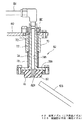
エア供給ノズル62は、昇降ロッド58の上端に水平の取付板60を介して取り付けられており、図4に示すように、取付板60の下面側に固定された保持筒70内にブッシュ72を介して上下に摺動可能な通路部材74と、この通路部材74の下端に形成されたフランジ74aの下面側に取り付けられている対向部材76を備えている。前記保持筒70の下端とフランジ74aの上面との間に緩衝用スプリング78が介装され、通路部材74および対向部材76を下方へ付勢している。通路部材74の、取付板60よりも上方に突出している部分の外周面にストッパ80が固定されており、緩衝用スプリング78による通路部材74の下降限を規制している。エア供給ノズル62が下降して対向部材76がペットボトル2の口部等に当接した際の衝撃をこの緩衝用スプリング78によって吸収する。なお、このエア供給ノズル62は、全体としてステンレスによって製作されており、対向部材76だけが、容器2の口部に傷を付けず、また、密封する場合の密閉性を向上させるためにシリコーン製になっている。   The air supply nozzle 62 is attached to the upper end of the lifting rod 58 via a horizontal attachment plate 60. As shown in FIG. 4, a bush 72 is provided in a holding cylinder 70 fixed to the lower surface side of the attachment plate 60. And a counter member 76 attached to the lower surface side of a flange 74a formed at the lower end of the channel member 74. A buffering spring 78 is interposed between the lower end of the holding cylinder 70 and the upper surface of the flange 74a to urge the passage member 74 and the opposing member 76 downward. A stopper 80 is fixed to the outer peripheral surface of the portion of the passage member 74 that protrudes above the mounting plate 60, and restricts the lowering limit of the passage member 74 by the buffer spring 78. The shock when the air supply nozzle 62 descends and the opposing member 76 comes into contact with the mouth of the PET bottle 2 or the like is absorbed by the buffer spring 78. The air supply nozzle 62 is made of stainless as a whole, and only the facing member 76 does not damage the mouth of the container 2 and is made of silicone in order to improve the sealing performance when sealing. It has become.

前記通路部材74の内部はエア通路74bになっており、この通路部材74の下端のフランジ74aと前記対向部材76の内部に、エア通路74bを介して供給されてきたエアを絞って噴射する小径通路82aを有するステンレス製のノズル部材82が設けられている。この対向部材76を昇降させる円筒状カム66および昇降ロッド58等からなる昇降機構によって、請求項に記載した昇降手段が構成されている。この昇降手段によってグリッパ54と対向部材76とを接近させて、エア供給ノズル62を容器2の口部2dに対する吹き込み位置に位置させる。本実施例では、対向部材76と容器2の口部2dの接触を避けて、口部2dを密封せずに対向部材76を口部2dに接触しない最大限まで接近させて、密封に近い極力洩れの少ない状態で気体を吹き込むようにしており、この状態での最接近した口部2dに対するエア供給ノズル62の位置を吹き込み位置としている。この際、容器2はフランジ2eの下面をグリッパ54で支持しているため、胴部2aの潰れの有無や程度に係わらず容器2を常に同じ姿勢で支持することができ、対向部材76を口部2dに接触させない最大限まで接近させて位置させることができる。なお、対向部材76を口部2dに押圧させて密封するよう構成することも可能であり、この場合には、押圧した状態の口部2dに対するエア供給ノズル62の位置が吹き込み位置となる。この際、口部2dに対する下方への押圧力は、フランジ2eの下面をグリッパ54で支持することにより受けられ、胴部2aに作用することはなく、胴部2aが潰れることはない。なお、昇降手段による対向部材76と支持部材であるグリッパ54の接近は、対向部材76を昇降する構成に限らず、同様の昇降機構を用いてグリッパ54を昇降させても良いし、対向部材76とグリッパ54の両方を昇降させるよう構成しても良い。   The inside of the passage member 74 is an air passage 74b, and a small diameter that squeezes and injects the air supplied through the air passage 74b into the flange 74a at the lower end of the passage member 74 and the opposing member 76. A stainless nozzle member 82 having a passage 82a is provided. The elevating mechanism described in the claims is constituted by an elevating mechanism including a cylindrical cam 66 for elevating and lowering the facing member 76, an elevating rod 58, and the like. The gripper 54 and the facing member 76 are brought close to each other by this lifting means, and the air supply nozzle 62 is positioned at the blowing position with respect to the mouth 2 d of the container 2. In this embodiment, contact between the opposing member 76 and the mouth portion 2d of the container 2 is avoided, the mouth portion 2d is not sealed, and the opposing member 76 is brought close to the mouth 2d to the maximum extent, and as close to sealing as possible. Gas is blown in a state where there is little leakage, and the position of the air supply nozzle 62 relative to the closest opening 2d in this state is the blowing position. At this time, since the container 2 supports the lower surface of the flange 2e with the gripper 54, the container 2 can always be supported in the same posture regardless of whether or not the body portion 2a is crushed, and the opposing member 76 is opened. It can be positioned as close as possible without contacting the part 2d. It is also possible to configure the facing member 76 to be pressed against the mouth 2d and seal it. In this case, the position of the air supply nozzle 62 relative to the mouth 2d in the pressed state is the blowing position. At this time, the downward pressing force with respect to the mouth portion 2d is received by supporting the lower surface of the flange 2e with the gripper 54, does not act on the body portion 2a, and the body portion 2a is not crushed. The approach of the facing member 76 and the gripper 54 that is the supporting member by the lifting means is not limited to the configuration in which the facing member 76 is lifted or lowered, and the gripper 54 may be lifted or lowered by using a similar lifting mechanism. The gripper 54 may be lifted and lowered.

通路部材74内のエア通路74bの上端は、エア供給用のチューブ84に接続されている。各エア供給ノズル62に接続されたエア供給用チューブ84の他端は、図2に示すように、前記回転軸52の上端に取り付け筒86を介して固定されている分配マニホールド88に接続されており、上方から送られてきたエアはこの分配マニホールド88によって各エア供給ノズル62に分配供給される。各エア供給用チューブ84はフレキシブルチューブであり、前記昇降ロッド58および通路部材74の上下動に追従することができる。   The upper end of the air passage 74 b in the passage member 74 is connected to an air supply tube 84. As shown in FIG. 2, the other end of the air supply tube 84 connected to each air supply nozzle 62 is connected to a distribution manifold 88 fixed to the upper end of the rotating shaft 52 via a mounting cylinder 86. The air sent from above is distributed and supplied to each air supply nozzle 62 by the distribution manifold 88. Each air supply tube 84 is a flexible tube, and can follow the vertical movement of the elevating rod 58 and the passage member 74.

前記各エア供給ノズル62に供給されるエアは、図5に示すように、圧縮エア供給管90を介して図示しない圧縮エア供給源(図5の左方に接続されている)から送られる。圧縮エア供給配管90には、無菌フィルタ92およびヒータ94が接続されており、その上流側に開閉弁96が設けられ、下流側は二つの通路90a、90bに分岐している。分岐した一方のメイン通路90aはレギュレータ98および開閉弁100を介して、前記第1チャンバ6の天面6b(図2参照)に取り付けたロータリジョイント102に接続されている。このロータリジョイント102のチャンバ内部側の回転部が無菌フィルタ104を介して前記分配マニホールド88に接続されている。なお、本発明は、これら供給された気体を流通させる通路のうち、ロータリジョイント102より下流の、無菌フィルタ104、分配マニホールド88、エア供給用チューブ84およびこれらを連結する各配管からなるチャンバ6内に配置された給気管を対象に結露の発生を防止するものである。   As shown in FIG. 5, the air supplied to each air supply nozzle 62 is sent from a compressed air supply source (not shown) (connected to the left in FIG. 5) via a compressed air supply pipe 90. A sterile filter 92 and a heater 94 are connected to the compressed air supply pipe 90. An on-off valve 96 is provided on the upstream side, and the downstream side is branched into two passages 90a and 90b. One branched main passage 90a is connected to a rotary joint 102 attached to the top surface 6b (see FIG. 2) of the first chamber 6 via a regulator 98 and an on-off valve 100. A rotary part inside the chamber of the rotary joint 102 is connected to the distribution manifold 88 via a sterile filter 104. In the present invention, among the passages through which the supplied gas flows, the inside of the chamber 6 comprising the aseptic filter 104, the distribution manifold 88, the air supply tube 84, and the pipes connecting them, downstream from the rotary joint 102. This prevents the occurrence of condensation on the air supply pipe arranged in the section.

エア供給ノズル62、特に下端に設けた対向部材76は、開口状態で搬送されるペットボトル2の直上に配置され、口部に最も接近する部分であるため、結露が発生することを最も避けなければならないので、エア供給ノズル62の移動経路の下方側に、対向部材76の結露を防止する結露防止手段を設けている。この実施例では、結露防止手段として対向部材76の下面に向けてエアを噴射する斜め方向の噴射ノズル106を設けている(図4参照)。前記圧縮エア供給配管90の下流側の分岐通路90bは、前記メイン通路90aと同様にレギュレータ108および開閉弁110が設けられており、この分岐通路90bが噴射ノズル106に接続されている。よって、噴射ノズル106から噴射されるエアは、無菌フィルタ92を通過した無菌エアであり、ヒータ94で昇温されている。この噴射ノズル106は、図1に示すように、第2導入ホイール20が第1導入ホイール18から受け取って回転搬送し、第3導入ホイール22に引き渡すペットボトル2と干渉しないように、ペットボトル2の搬送経路以外の部分に設けられている。   The air supply nozzle 62, particularly the opposing member 76 provided at the lower end, is disposed immediately above the PET bottle 2 conveyed in an open state and is the portion closest to the mouth portion, so that condensation should be avoided most. Therefore, dew condensation prevention means for preventing dew condensation of the facing member 76 is provided below the movement path of the air supply nozzle 62. In this embodiment, an oblique injection nozzle 106 for injecting air toward the lower surface of the facing member 76 is provided as a dew condensation prevention means (see FIG. 4). The branch passage 90b on the downstream side of the compressed air supply pipe 90 is provided with a regulator 108 and an on-off valve 110, as with the main passage 90a, and this branch passage 90b is connected to the injection nozzle 106. Therefore, the air injected from the injection nozzle 106 is aseptic air that has passed through the aseptic filter 92 and is heated by the heater 94. As shown in FIG. 1, the injection nozzle 106 receives the PET bottle 2 so as not to interfere with the PET bottle 2 that the second introduction wheel 20 receives from the first introduction wheel 18 and rotates and conveys it to the third introduction wheel 22. It is provided in parts other than the conveyance path.

前記構成の容器加圧装置の作動について説明する。図示しないボトル成型機によって成形されたペットボトル2は、導入エアコンベヤ4によって搬送されて第1チャンバ6内に導入される。第1チャンバ6内には、複数の導入ホイール18、20、22が配置されており、導入されたペットボトル2は、各導入ホイール18、20、22によって首部を支持され回転搬送されつつ順次受け渡しが行われる。第2導入ホイール20には容器加圧装置が設けられており、この容器加圧装置によって、ペットボトル2は内部にエアを吹き込まれて加圧される。導入エアコンベヤ4では、ペットボトル2の首部2cに形成されているフランジ2eの下面側を支持し、後方からエアを吹き付けることによりペットボトル2を搬送する。その搬送過程でペットボトル2同士が衝突する等により変形してしまう場合がある。このようなペットボトル2は、各処理機(滅菌機26、リンサ30、フィラ36およびキャッパ42)内に搬入される前に、第2導入ホイール20に設けられている容器加圧装置で元の形状に復元される。   The operation of the container pressurizing apparatus having the above-described configuration will be described. The PET bottle 2 molded by a bottle molding machine (not shown) is conveyed by the introduction air conveyor 4 and introduced into the first chamber 6. A plurality of introduction wheels 18, 20, 22 are arranged in the first chamber 6, and the introduced PET bottles 2 are sequentially delivered while being supported by the necks by the introduction wheels 18, 20, 22 and being rotated and conveyed. Is done. The second introduction wheel 20 is provided with a container pressurizing device, and the PET bottle 2 is pressurized by blowing air into the inside by the container pressurizing device. The introduction air conveyor 4 supports the lower surface side of the flange 2e formed on the neck 2c of the PET bottle 2, and transports the PET bottle 2 by blowing air from the rear. There is a case where the plastic bottle 2 is deformed due to a collision or the like in the conveyance process. Such a plastic bottle 2 is returned to its original state by a container pressurizing device provided on the second introduction wheel 20 before being carried into each processing machine (sterilizer 26, rinser 30, filler 36 and capper 42). Restored to shape.

第1導入ホイール18のグリッパ53から第2導入ホイール20に引き渡されたペットボトル2は、第2導入ホイール20のグリッパ54に把持されて回転搬送される。グリッパ54がエア吹き込み開始位置Bに到達すると、円筒状カム66のカム面の形状に従ってカムフォロア68が下降するとともに、昇降ロッド58および取付板60を介してこれと一体のエア供給ノズル62が下降する。エア供給ノズル62の下端には対向部材76が取り付けられており、この対向部材76と下方のグリッパ54とを接近させることにより、対向部材76の下面がペットボトル2の口部に接近してペットボトル2の口部2dに対する吹き込み位置に位置する。   The PET bottle 2 delivered from the gripper 53 of the first introduction wheel 18 to the second introduction wheel 20 is gripped by the gripper 54 of the second introduction wheel 20 and rotated and conveyed. When the gripper 54 reaches the air blowing start position B, the cam follower 68 is lowered according to the shape of the cam surface of the cylindrical cam 66, and the air supply nozzle 62 integral therewith is lowered via the lifting rod 58 and the mounting plate 60. . A counter member 76 is attached to the lower end of the air supply nozzle 62. By bringing the counter member 76 and the lower gripper 54 close to each other, the lower surface of the counter member 76 approaches the mouth of the PET bottle 2 and the pet. It is located in the blowing position for the mouth 2d of the bottle 2.

運転中は、圧縮エア供給配管90の上流側の開閉弁96および下流側の分岐したメイン通路90aの開閉弁100を開放してあり、エア供給ノズル62に圧縮エアを供給している。供給される圧縮エアは、開放した上流側の開閉弁96および無菌フィルタ92を通った後、ヒータ94を通過して加熱される。加熱されて昇温された圧縮エアは、レギュレータ98により圧力を調整され、下流側の開閉弁100を通過して、第1チャンバ6の天面6bに設置されたロータリジョイント102に送られる。さらに、第1チャンバ6内の無菌フィルタ104により再度浄化されたエアは、分配マニホールド88によって分配されて各エア供給チューブ84からエア供給ノズル62に送られる。送られたエアは、エア供給ノズル62の通路部材74の内部に形成されたエア通路74bを通り、さらに、ノズル部82の小径通路82aからペットボトル2内に吹き込まれてこのペットボトル2内を加圧する。ペットボトル2が変形していた場合には内部側からの圧力で正常な形状に復帰する。ペットボトル2およびエア供給ノズル62が加圧終了位置Cに到達すると、円筒状カム66により昇降ロッド58およびエア供給ノズル62が上昇して、対向部材76がペットボトル2の口部から離れてペットボトル2内を開放する。なお、この実施例では、運転中は、エア供給ノズル62から常時無菌化され昇温された圧縮エアが吹き出されている。   During operation, the on-off valve 96 on the upstream side of the compressed air supply pipe 90 and the on-off valve 100 of the branched main passage 90 a on the downstream side are opened, and compressed air is supplied to the air supply nozzle 62. The supplied compressed air passes through the heater 94 after being passed through the opened upstream-side on-off valve 96 and the aseptic filter 92, and is heated. The compressed air heated and heated is adjusted in pressure by the regulator 98, passes through the on-off valve 100 on the downstream side, and is sent to the rotary joint 102 installed on the top surface 6 b of the first chamber 6. Further, the air purified again by the aseptic filter 104 in the first chamber 6 is distributed by the distribution manifold 88 and sent from each air supply tube 84 to the air supply nozzle 62. The sent air passes through the air passage 74b formed in the passage member 74 of the air supply nozzle 62, and is further blown into the plastic bottle 2 from the small diameter passage 82a of the nozzle portion 82. Pressurize. When the PET bottle 2 is deformed, it returns to a normal shape by the pressure from the inside. When the PET bottle 2 and the air supply nozzle 62 reach the pressurization end position C, the cylindrical cam 66 raises the elevating rod 58 and the air supply nozzle 62 so that the opposing member 76 moves away from the mouth of the PET bottle 2 and moves to the pet. The inside of the bottle 2 is opened. In this embodiment, during operation, compressed air that has been sterilized and heated at all times is blown out from the air supply nozzle 62.

前述のようにアセプティックチャンバ内は滅菌機26やリンサ30を設置しているため外部雰囲気より高温多湿の環境にあり、常温のエアを送ると温度差により無菌フィルタ104、分配マニホールド88、エア供給用チューブ84等からなる供給管やエア供給ノズル62の内部が、チャンバ内の温度に対して冷却されて表面に結露を生じてしまうが、この実施例では、圧縮エア供給配管90に設けたヒータ94によってエアを加熱してから供給しているので、結露の発生を防止することができる。この実施例では、容器加圧装置を設置している第1チャンバ6内の雰囲気温度が60°C程度で、供給される圧縮エアの温度は50〜60°C程度に設定している。なお、チャンバ内の温度は滅菌条件等により変更されるので、供給する圧縮エアの温度は50〜60°Cに限るものではなく、チャンバ内の温度付近まで加温すればよい。   As described above, since the sterilizer 26 and the rinser 30 are installed in the aseptic chamber, it is in a hot and humid environment from the outside atmosphere. When air at normal temperature is sent, the sterile filter 104, distribution manifold 88, and air supply are caused by the temperature difference. Although the inside of the supply pipe and the air supply nozzle 62 composed of the tube 84 and the like is cooled with respect to the temperature in the chamber to cause condensation on the surface, in this embodiment, the heater 94 provided in the compressed air supply pipe 90 Since the air is supplied after being heated, the occurrence of condensation can be prevented. In this embodiment, the atmospheric temperature in the first chamber 6 in which the container pressurizing apparatus is installed is set to about 60 ° C., and the temperature of the supplied compressed air is set to about 50 to 60 ° C. Since the temperature in the chamber is changed depending on the sterilization conditions and the like, the temperature of the compressed air to be supplied is not limited to 50 to 60 ° C., and it may be heated to near the temperature in the chamber.

第2導入ホイール20で、変形していたペットボトル2は修復され、正常なペットボトル2はそのまま第3の導入ホイール22に引き渡される。第3導入ホイール22に保持されたペットボトル2は、第1チャンバ6から第2チャンバ8内に導入され、第2チャンバ8内に設置されている滅菌機26に供給されて滅菌される。   The deformed plastic bottle 2 is repaired by the second introduction wheel 20, and the normal plastic bottle 2 is handed over to the third introduction wheel 22 as it is. The PET bottle 2 held on the third introduction wheel 22 is introduced from the first chamber 6 into the second chamber 8 and supplied to the sterilizer 26 installed in the second chamber 8 to be sterilized.

一方、グリッパ54が把持していたペットボトル2を第3ホイール22に引き渡した後、第2導入ホイール20に設けられたエア供給ノズル62は、回転移動して噴射ノズル106の位置に到達する。この噴射ノズル106には、前記圧縮エア供給配管90の分岐通路90bが接続されており、ヒータ94で加熱されたエアがレギュレータ108および開閉弁110を通って供給され、エア供給ノズル62の下端に設けられている対向部材76の下面に吹き付けられる。前記加圧用のエアがヒータ94によって昇温されて供給されているので、結露の発生は低く抑えられ水滴の落下等は防止されるが、対向部材76はペットボトル2の口部2dに対向して最接近する部位であるため、僅かでも対向部材76の表面に結露が生じていると好ましくないので、ペットボトル2に対向する下面側に昇温された無菌エアを吹き付けて結露が発生しないようにしている。すなわち、本実施例では、対向部材76に昇温された無菌エアを吹き付けることで、対向部材76を容器加圧装置を設置した第1チャンバ6内の温度付近まで加温し、結露の発生を防止するようにしている。また、無菌エアを噴射するので対向部材76やアセプティックチャンバ内の雰囲気を汚染することはない。本実施例では結露防止手段として、噴射ノズル106、ヒータ94、噴射ノズル106にエアを供給する分岐通路90b等により、対向部材76を加温する加温手段が構成されている。なお、ペットボトル2への充填を行う生産運転を開始する前の準備工程においてはヒータ94による加熱が充分でない場合があるので、このような運転開始前には対向部材76に無菌の圧縮エアを吹き付けて、結露による水滴を噴射圧にて吹き飛ばすことで対向部材76の表面を乾燥させておくようにすることが好ましい。なお、無菌エアを吹き付けて対向部材76の表面を乾燥させて結露を防止する結露防止手段としては、高温の無菌エアで蒸発させること、無菌エアの噴射圧で吹き飛ばすこと、乾燥させたドライ無菌エアを用いて乾燥させること等が含まれる。   On the other hand, after handing over the PET bottle 2 held by the gripper 54 to the third wheel 22, the air supply nozzle 62 provided on the second introduction wheel 20 rotates and reaches the position of the injection nozzle 106. A branch passage 90 b of the compressed air supply pipe 90 is connected to the injection nozzle 106, and air heated by the heater 94 is supplied through the regulator 108 and the on-off valve 110, and is supplied to the lower end of the air supply nozzle 62. It sprays on the lower surface of the opposing member 76 provided. Since the pressurizing air is heated and supplied by the heater 94, the occurrence of condensation is kept low and water drops are prevented, but the facing member 76 faces the mouth 2d of the plastic bottle 2. Therefore, it is not preferable that condensation occurs on the surface of the facing member 76 even slightly, so that the heated aseptic air is blown to the lower surface facing the PET bottle 2 so that condensation does not occur. I have to. That is, in the present embodiment, by spraying aseptic air heated to the opposing member 76, the opposing member 76 is heated to near the temperature in the first chamber 6 in which the container pressurizing device is installed, and condensation is generated. I try to prevent it. Further, since the sterilized air is injected, the atmosphere in the opposing member 76 and the aseptic chamber is not contaminated. In this embodiment, as the dew condensation preventing means, a heating means for heating the facing member 76 is constituted by the injection nozzle 106, the heater 94, the branch passage 90b for supplying air to the injection nozzle 106, and the like. Note that in the preparatory step before starting the production operation for filling the PET bottle 2, heating by the heater 94 may not be sufficient, so before starting such operation, sterile compressed air is supplied to the opposing member 76. It is preferable to dry the surface of the opposing member 76 by spraying and blowing off water droplets caused by dew condensation with an injection pressure. In addition, as dew condensation prevention means which sprays aseptic air and dries the surface of the opposing member 76 to prevent dew condensation, evaporating with high temperature aseptic air, blowing away with aseptic air injection pressure, dried dry aseptic air For example, drying with a sucrose.

第2チャンバ8内で滅菌機26に供給されて滅菌されたペットボトル2は、第1中間ホイール28に保持されて第3チャンバ10内に設置されているリンサ30に送られて洗浄される。その後、ペットボトル2は、第2中間ホイール34を介して第4チャンバ12内のフィラ36に送られて液体を充填され、続いて、第3中間ホイール40を介してキャッパ42に送られてキャッピングが行われる。充填およびキャッピングが行われたペットボトル2は、第1排出ホイール44および第2排出ホイール46を介して排出エアコンベヤ16に引き渡されて次の工程に送られる。   The PET bottle 2 supplied to the sterilizer 26 and sterilized in the second chamber 8 is held by the first intermediate wheel 28 and sent to the rinser 30 installed in the third chamber 10 to be cleaned. Thereafter, the PET bottle 2 is sent to the filler 36 in the fourth chamber 12 via the second intermediate wheel 34 and filled with liquid, and then sent to the capper 42 via the third intermediate wheel 40 for capping. Is done. The filled and capped PET bottle 2 is delivered to the discharge air conveyor 16 via the first discharge wheel 44 and the second discharge wheel 46 and sent to the next step.

なお、前記実施例では、圧縮エア供給源から圧縮エアを供給しているが、圧縮エアに限るものではなく、口部2dに対向部材76を押圧させて密封するよう構成した場合には、加圧していないエアを密封した容器内に送り込み、変形した容器を復元できる圧力まで加圧してもよい。また、対向部材76に結露が生じることを防止する結露防止手段として、対向部材76に加熱した空気を吹き付ける噴射ノズル106を設けたが、対向部材76を加温する加温手段としては、このように昇温したエアを吹き付ける構成に限るものではなく、例えば、対向部材76を直接加熱するヒータをエア供給ノズル62の移動経路の直下に設けるようにしても良い。この場合も、ペットボトル2の搬送経路以外の部分に設けることは言うまでもない。また、対向部材76を直接加熱するヒータを外部に設けるだけでなく、対向部材76の内側に内蔵するようにしても良い。さらに、結露防止手段の加温手段としては、エア供給ノズル62から加熱した圧縮エアを常時吹き出させることにより、対向部材76を加温させるようにしたものも含まれる。さらに、前述のように高温の滅菌ガスや蒸気を扱う滅菌機や、温水や加温した薬液を扱うリンサが配置されていない場合にも、内部に設けたフィラやキャッパ等の機器から発生する熱によりチャンバ内部は外部雰囲気よりも高温となるため、このような装置構成に対しても本発明は有効である。   In the above embodiment, the compressed air is supplied from the compressed air supply source. However, the compressed air is not limited to the compressed air. If the opposed member 76 is pressed against the mouth portion 2d and sealed, the compressed air is supplied. Air that has not been pressurized may be sent into a sealed container and pressurized to a pressure at which the deformed container can be restored. Further, as the dew condensation preventing means for preventing the condensation on the facing member 76, the spray nozzle 106 for blowing the heated air to the facing member 76 is provided. However, as the heating means for heating the facing member 76, this is the case. For example, a heater that directly heats the facing member 76 may be provided directly below the movement path of the air supply nozzle 62. In this case, it goes without saying that it is provided in a portion other than the conveyance path of the plastic bottle 2. In addition, a heater that directly heats the opposing member 76 may be provided outside, and may be incorporated inside the opposing member 76. Furthermore, the heating means of the dew condensation prevention means includes a means in which the opposed member 76 is heated by constantly blowing compressed air heated from the air supply nozzle 62. Furthermore, even if there is no sterilizer that handles high-temperature sterilization gas or steam as described above, or a rinser that handles hot water or heated chemicals, heat generated from equipment such as fillers and cappers installed inside As a result, the temperature inside the chamber becomes higher than that of the external atmosphere, and the present invention is effective for such an apparatus configuration.

容器加圧装置を備えたアセプティック充填ラインの全体の構成を示す平面図である。(実施例1)It is a top view which shows the whole structure of the aseptic filling line provided with the container pressurization apparatus. Example 1 容器加圧装置の縦断面図である。It is a longitudinal cross-sectional view of a container pressurization apparatus. エアコンベヤおよびエアコンベヤによって搬送される容器を示す図である。It is a figure which shows the container conveyed by an air conveyor and an air conveyor. 前記容器加圧装置に設けられたエア供給ノズルの縦断面図である。It is a longitudinal cross-sectional view of the air supply nozzle provided in the said container pressurization apparatus. 前記エア供給ノズルおよび給気管にエアを供給するエア供給配管の構成を示す図である。It is a figure which shows the structure of the air supply piping which supplies air to the said air supply nozzle and an air supply pipe.

符号の説明Explanation of symbols

2 樹脂製容器(ペットボトル)
2c 容器の首部
2d 口部
54 支持部材(グリッパ)
62 給気ノズル(エア供給ノズル)
66 カム(昇降手段)
68 カムフォロア(昇降手段)
90 給気管(圧縮エア供給管)
94 ヒータ
106 結露防止手段(噴射ノズル)
2 Resin container (PET bottle)
2c neck of container 2d mouth 54 support member (gripper)
62 Air supply nozzle (Air supply nozzle)
66 Cam (lifting means)
68 Cam follower
90 Air supply pipe (compressed air supply pipe)
94 Heater 106 Condensation prevention means (injection nozzle)

Claims (6)

気体が供給される給気管と、この給気管から供給される気体を吹き出す給気ノズルとを備え、給気ノズルから樹脂製容器内に気体を吹き込んで容器内部を加圧する容器加圧装置において、
前記給気管および給気ノズルの結露を防止する結露防止手段を備えたことを特徴とする容器加圧装置。
In a container pressurizing apparatus that includes an air supply pipe to which gas is supplied and an air supply nozzle that blows out gas supplied from the air supply pipe, and pressurizes the inside of the container by blowing gas into the resin container from the air supply nozzle.
A container pressurizing device comprising condensation prevention means for preventing condensation on the supply pipe and the supply nozzle.
前記結露防止手段として、前記給気管に供給される気体を加熱するヒータを設け、このヒータによって昇温させた気体を給気管へ供給し、給気ノズルから吹き出すことを特徴とする請求項1に記載の容器加圧装置。   The said condensation prevention means is provided with the heater which heats the gas supplied to the said air supply pipe | tube, The gas heated up with this heater is supplied to an air supply pipe | tube, It blows off from an air supply nozzle. The container pressurizing apparatus as described. 前記給気ノズルに向けて無菌エアを吹き付ける噴射ノズルを設けたことを特徴とする請求項2に記載の容器加圧装置。   The container pressurizing apparatus according to claim 2, wherein an injection nozzle that blows aseptic air toward the air supply nozzle is provided. 前記給気ノズルを加温する加温手段を設け、加温することで給気ノズルの結露を防止するようにしたことを特徴とする請求項1ないし請求項3のいずれかに記載の容器加圧装置。   4. The container heater according to claim 1, wherein a heating means for heating the air supply nozzle is provided to prevent condensation of the air supply nozzle by heating. Pressure device. 前記ヒータによって昇温させた気体を、前記噴射ノズルから噴射することを特徴とする請求項3に記載の容器加圧装置。   The container pressurizing apparatus according to claim 3, wherein the gas heated by the heater is injected from the injection nozzle. 前記給気管および給気ノズルを、内部雰囲気が外部よりも高温となるチャンバ内に設置して、チャンバ内で給気ノズルから樹脂製容器内に気体を吹き込んで容器内部を加圧することを特徴とする請求項1ないし請求項5のいずれかに記載の容器加圧装置。   The air supply pipe and the air supply nozzle are installed in a chamber in which the internal atmosphere is hotter than the outside, and the inside of the container is pressurized by blowing gas from the air supply nozzle into the resin container in the chamber. The container pressurizing apparatus according to any one of claims 1 to 5.
JP2008196094A 2008-07-30 2008-07-30 Container pressurizer Active JP5259290B2 (en)

Priority Applications (1)

Application Number Priority Date Filing Date Title
JP2008196094A JP5259290B2 (en) 2008-07-30 2008-07-30 Container pressurizer

Applications Claiming Priority (1)

Application Number Priority Date Filing Date Title
JP2008196094A JP5259290B2 (en) 2008-07-30 2008-07-30 Container pressurizer

Publications (2)

Publication Number Publication Date
JP2010030645A JP2010030645A (en) 2010-02-12
JP5259290B2 true JP5259290B2 (en) 2013-08-07

Family

ID=41735648

Family Applications (1)

Application Number Title Priority Date Filing Date
JP2008196094A Active JP5259290B2 (en) 2008-07-30 2008-07-30 Container pressurizer

Country Status (1)

Country Link
JP (1) JP5259290B2 (en)

Families Citing this family (3)

* Cited by examiner, † Cited by third party
Publication number Priority date Publication date Assignee Title
ES2644996T3 (en) * 2014-10-29 2017-12-01 Indag Gesellschaft für Industriebedarf mbH & Co. Betriebs KG Device for inserting a medium into a container
JP6576076B2 (en) * 2015-03-31 2019-09-18 小林製薬株式会社 Container manufacturing method
JP6956495B2 (en) * 2017-02-28 2021-11-02 サントリーホールディングス株式会社 Filling method and filling equipment

Family Cites Families (7)

* Cited by examiner, † Cited by third party
Publication number Priority date Publication date Assignee Title
JPH0781926B2 (en) * 1985-09-27 1995-09-06 株式会社吉野工業所 Method and apparatus for inspecting air tightness of synthetic resin bottle container
JPH068151B2 (en) * 1988-05-09 1994-02-02 キッコーマン株式会社 How to fix deformed plastic bottles
JPH06127530A (en) * 1992-10-19 1994-05-10 Kunoole Shokuhin Kk Device for expanding soft container and for correcting shape thereof
JPH1111588A (en) * 1997-06-24 1999-01-19 Lion Corp Preliminary treatment method for charging and device thereof of fragile container
JP3444174B2 (en) * 1998-01-21 2003-09-08 靜甲株式会社 Container processing equipment
JP2000326921A (en) * 1999-05-13 2000-11-28 Hokkai Can Co Ltd Inert gas charging device
JP2005082219A (en) * 2003-09-10 2005-03-31 Nihon Tetra Pak Kk Filling-up machine

Also Published As

Publication number Publication date
JP2010030645A (en) 2010-02-12

Similar Documents

Publication Publication Date Title
US10449708B2 (en) Method and apparatus for sterilizing bottle
US10137217B2 (en) Method and apparatus for sterilizing preform
CN110621609B (en) Aseptic filling machine and aseptic filling method
US6328928B1 (en) Method and for preparing container for filling, and method of filling container
JP6565171B2 (en) Container transfer control device
JP2014240304A (en) Beverage filling method and device
CN105939937B (en) Method and apparatus for sterilizing container
US11261072B2 (en) Aseptic filling machine and aseptic filling method
JP6819709B2 (en) Container sterilizer, content filling system, container sterilization method and content filling method
JP5259290B2 (en) Container pressurizer
JP6860862B2 (en) Carbonated drink aseptic filling system
WO2017038584A1 (en) Sterile filling system, container disinfecting unit, and sterile filling method
JP6330876B2 (en) Aseptic filling machine and aseptic filling method
CN107530946B (en) Method and apparatus for molding aseptic container, and method and apparatus for aseptic filling
JP6911964B2 (en) Bottle sterilization method and equipment
JP7193700B2 (en) Filling system and filling method
JP7428169B2 (en) Method for cleaning containers sealed by aseptic filling machine and aseptic filling machine

Legal Events

Date Code Title Description
A621 Written request for application examination

Free format text: JAPANESE INTERMEDIATE CODE: A621

Effective date: 20110330

A711 Notification of change in applicant

Free format text: JAPANESE INTERMEDIATE CODE: A712

Effective date: 20121227

Free format text: JAPANESE INTERMEDIATE CODE: A711

Effective date: 20121227

A131 Notification of reasons for refusal

Free format text: JAPANESE INTERMEDIATE CODE: A131

Effective date: 20130108

A521 Request for written amendment filed

Free format text: JAPANESE INTERMEDIATE CODE: A821

Effective date: 20121227

A521 Request for written amendment filed

Free format text: JAPANESE INTERMEDIATE CODE: A523

Effective date: 20130308

TRDD Decision of grant or rejection written
A01 Written decision to grant a patent or to grant a registration (utility model)

Free format text: JAPANESE INTERMEDIATE CODE: A01

Effective date: 20130409

A61 First payment of annual fees (during grant procedure)

Free format text: JAPANESE INTERMEDIATE CODE: A61

Effective date: 20130424

FPAY Renewal fee payment (event date is renewal date of database)

Free format text: PAYMENT UNTIL: 20160502

Year of fee payment: 3

R150 Certificate of patent or registration of utility model

Ref document number: 5259290

Country of ref document: JP

Free format text: JAPANESE INTERMEDIATE CODE: R150

Free format text: JAPANESE INTERMEDIATE CODE: R150

R250 Receipt of annual fees

Free format text: JAPANESE INTERMEDIATE CODE: R250

R250 Receipt of annual fees

Free format text: JAPANESE INTERMEDIATE CODE: R250

R250 Receipt of annual fees

Free format text: JAPANESE INTERMEDIATE CODE: R250

R250 Receipt of annual fees

Free format text: JAPANESE INTERMEDIATE CODE: R250

S111 Request for change of ownership or part of ownership

Free format text: JAPANESE INTERMEDIATE CODE: R313117

R350 Written notification of registration of transfer

Free format text: JAPANESE INTERMEDIATE CODE: R350

R250 Receipt of annual fees

Free format text: JAPANESE INTERMEDIATE CODE: R250

R250 Receipt of annual fees

Free format text: JAPANESE INTERMEDIATE CODE: R250

R250 Receipt of annual fees

Free format text: JAPANESE INTERMEDIATE CODE: R250

R250 Receipt of annual fees

Free format text: JAPANESE INTERMEDIATE CODE: R250

R250 Receipt of annual fees

Free format text: JAPANESE INTERMEDIATE CODE: R250