JP5259286B2 - 3D object recognition system and inventory system using the same - Google Patents
3D object recognition system and inventory system using the same Download PDFInfo
- Publication number
- JP5259286B2 JP5259286B2 JP2008184686A JP2008184686A JP5259286B2 JP 5259286 B2 JP5259286 B2 JP 5259286B2 JP 2008184686 A JP2008184686 A JP 2008184686A JP 2008184686 A JP2008184686 A JP 2008184686A JP 5259286 B2 JP5259286 B2 JP 5259286B2
- Authority
- JP
- Japan
- Prior art keywords
- sensor
- data
- arrangement
- object model
- model
- Prior art date
- Legal status (The legal status is an assumption and is not a legal conclusion. Google has not performed a legal analysis and makes no representation as to the accuracy of the status listed.)
- Expired - Fee Related
Links
Images


Classifications
-
- G—PHYSICS
- G06—COMPUTING OR CALCULATING; COUNTING
- G06Q—INFORMATION AND COMMUNICATION TECHNOLOGY [ICT] SPECIALLY ADAPTED FOR ADMINISTRATIVE, COMMERCIAL, FINANCIAL, MANAGERIAL OR SUPERVISORY PURPOSES; SYSTEMS OR METHODS SPECIALLY ADAPTED FOR ADMINISTRATIVE, COMMERCIAL, FINANCIAL, MANAGERIAL OR SUPERVISORY PURPOSES, NOT OTHERWISE PROVIDED FOR
- G06Q10/00—Administration; Management
- G06Q10/08—Logistics, e.g. warehousing, loading or distribution; Inventory or stock management
- G06Q10/087—Inventory or stock management, e.g. order filling, procurement or balancing against orders
-
- G—PHYSICS
- G06—COMPUTING OR CALCULATING; COUNTING
- G06V—IMAGE OR VIDEO RECOGNITION OR UNDERSTANDING
- G06V20/00—Scenes; Scene-specific elements
- G06V20/60—Type of objects
- G06V20/64—Three-dimensional [3D] objects
-
- G—PHYSICS
- G05—CONTROLLING; REGULATING
- G05D—SYSTEMS FOR CONTROLLING OR REGULATING NON-ELECTRIC VARIABLES
- G05D1/00—Control of position, course, altitude or attitude of land, water, air or space vehicles, e.g. using automatic pilots
- G05D1/02—Control of position or course in two dimensions
- G05D1/021—Control of position or course in two dimensions specially adapted to land vehicles
- G05D1/0231—Control of position or course in two dimensions specially adapted to land vehicles using optical position detecting means
- G05D1/0238—Control of position or course in two dimensions specially adapted to land vehicles using optical position detecting means using obstacle or wall sensors
-
- G—PHYSICS
- G05—CONTROLLING; REGULATING
- G05D—SYSTEMS FOR CONTROLLING OR REGULATING NON-ELECTRIC VARIABLES
- G05D1/00—Control of position, course, altitude or attitude of land, water, air or space vehicles, e.g. using automatic pilots
- G05D1/02—Control of position or course in two dimensions
- G05D1/021—Control of position or course in two dimensions specially adapted to land vehicles
- G05D1/0268—Control of position or course in two dimensions specially adapted to land vehicles using internal positioning means
- G05D1/0274—Control of position or course in two dimensions specially adapted to land vehicles using internal positioning means using mapping information stored in a memory device
-
- G—PHYSICS
- G06—COMPUTING OR CALCULATING; COUNTING
- G06F—ELECTRIC DIGITAL DATA PROCESSING
- G06F16/00—Information retrieval; Database structures therefor; File system structures therefor
- G06F16/50—Information retrieval; Database structures therefor; File system structures therefor of still image data
- G06F16/58—Retrieval characterised by using metadata, e.g. metadata not derived from the content or metadata generated manually
- G06F16/583—Retrieval characterised by using metadata, e.g. metadata not derived from the content or metadata generated manually using metadata automatically derived from the content
- G06F16/5854—Retrieval characterised by using metadata, e.g. metadata not derived from the content or metadata generated manually using metadata automatically derived from the content using shape and object relationship
Landscapes
- Engineering & Computer Science (AREA)
- Physics & Mathematics (AREA)
- General Physics & Mathematics (AREA)
- Theoretical Computer Science (AREA)
- Business, Economics & Management (AREA)
- Economics (AREA)
- Library & Information Science (AREA)
- Radar, Positioning & Navigation (AREA)
- Quality & Reliability (AREA)
- General Business, Economics & Management (AREA)
- Entrepreneurship & Innovation (AREA)
- Human Resources & Organizations (AREA)
- Marketing (AREA)
- Operations Research (AREA)
- Finance (AREA)
- Strategic Management (AREA)
- Tourism & Hospitality (AREA)
- Development Economics (AREA)
- Accounting & Taxation (AREA)
- Data Mining & Analysis (AREA)
- Databases & Information Systems (AREA)
- General Engineering & Computer Science (AREA)
- Multimedia (AREA)
- Aviation & Aerospace Engineering (AREA)
- Remote Sensing (AREA)
- Automation & Control Theory (AREA)
- Electromagnetism (AREA)
- Warehouses Or Storage Devices (AREA)
Description
本発明は、物体の状況を自動的に認識する3次元物体認識システム及びそれを用いた棚卸システムに関する。 The present invention relates to a three-dimensional object recognition system that automatically recognizes the state of an object and an inventory system using the same.
さまざまな分野における情報の増加に伴い、情報を如何に収集するか、また、どの様に管理し利用するかが非常に重要になってきている。物流現場においては、情報管理方法の一つとして、物品にバーコードを取り付けバーコードリーダで商品情報を読み取る、または、物品に電子タグを取り付け無線で商品情報を読み取り、商品出荷情報や在庫情報を企業間で共有することにより、検品や棚卸作業の省力化など、物流・工場・販売の現場に数々のメリットを提供することが可能である。 With the increase of information in various fields, how to collect information, how to manage and use it has become very important. At distribution sites, one of the information management methods is to attach a barcode to an article and read the product information with a barcode reader, or attach an electronic tag to the article and read the product information wirelessly to obtain product shipment information and inventory information. By sharing between companies, it is possible to provide a number of benefits to logistics, factories, and sales sites, such as labor saving in inspection and inventory work.
このような状況の中、自動的に物品数をカウントする棚卸システムとして、 棚に圧力センサを組み込むことにより、荷重で個数をカウントするものがある(特許文献1)。また、カメラ画像から物品の輪郭を抽出し、事前登録の特徴データファイルとの比較により物品個数をカウントするシステムもある(特許文献2)。 Under such circumstances, as an inventory system that automatically counts the number of articles, there is a system that counts the number by load by incorporating a pressure sensor into the shelf (Patent Document 1). There is also a system that extracts the outline of an article from a camera image and counts the number of articles by comparison with a pre-registered feature data file (Patent Document 2).
物品の棚卸し作業においては物品数のチェック及び位置管理が必須となる。現在の棚卸は、人手が必要で自動化されておらず、物品種別の管理に関してはバーコードを用いたものが主であり、個数の管理は人間の目視で行われているものが一般的である。RFIDなどの電子タグを無線で読み取ることにより、物品種別及び個数管理を同時に行う方法もあるが、読み落としの可能性があり、さらに導入にコストがかかることから、まだ実用化されていない。 Checking the number of items and managing the position are indispensable in the inventorying of items. The current inventory is not automated because it requires human labor, and the type of goods is mainly managed using barcodes, and the number of items is generally managed by human eyes. . There is a method of simultaneously managing the type and number of articles by wirelessly reading an RFID tag such as RFID, but it has not yet been put into practical use because there is a possibility that it will be read over and the introduction is costly.
物品の個数の管理については、特許文献1では、荷重で個数をカウントするため、重量測定のためのセンサを棚に取り付けておく必要があり、事前のインフラ整備が必須となる。また、全ての棚にセンサを取り付けるのは、特に広い倉庫においては現実的ではない。特許文献2では、カメラを動作させる装置を天井や壁面に取り付けておく必要があり、事前のインフラ整備が必須となる。また、カメラ動作が予め決まっているため、取得できるデータに制限がある上、カメラのみでの認識では特徴点抽出など計算も複雑である。
Regarding the management of the number of articles, in
特許文献1及び特許文献2では、倉庫内の荷物(物品)の位置管理に関しては言及されていない。
In
そこで、本発明の目的は、物品の状況を自動的に認識する3次元物体認識システム、及びその3次元物体認識システムを用いて、荷物(物品)の倉庫内の位置を認識し、個数をカウントすることにある。 Accordingly, an object of the present invention is to recognize a position of a package (article) in a warehouse by using a three-dimensional object recognition system that automatically recognizes the state of the article and the three-dimensional object recognition system, and count the number of pieces. There is to do.
本発明の望ましい態様は次のような、3次元物体認識システムまたは棚卸システムである。 A desirable mode of the present invention is the following three-dimensional object recognition system or inventory system.
物体までの距離を計測するセンサと、センサを移動させる移動機構と、センサと接続し、物体の少なくとも形状を格納する物体情報データベース、物体の配置パタンを格納する物体配置データベース、移動機構によるセンサの移動に伴うセンサからの、物体までの距離を計測したセンサデータとセンサデータを得たセンサの位置とを入力とし、センサの位置に応じてセンサデータを3次元空間内に統合した、物体の輪郭を示す統合データを出力するセンサデータ統合部、及び物体情報データベースに格納された物体の形状から物体モデルを作成し、物体配置データベースに格納された物体の配置パタンを参照して、作成した物体モデルと統合データとを比較して物体の実配置を示す物体実配置データを出力する物体比較演算部を有する計算機とを設けた3次元物体認識システムまたは棚卸システムである。 A sensor for measuring the distance to the object, a moving mechanism for moving the sensor, an object information database for storing at least the shape of the object connected to the sensor, an object arrangement database for storing the object arrangement pattern, and a sensor by the moving mechanism The contour of the object, which is input from the sensor data obtained by measuring the distance to the object from the sensor accompanying the movement and the sensor position from which the sensor data was obtained, and integrated in the 3D space according to the sensor position. An object model created from the shape of the object stored in the object information database and a sensor data integration unit that outputs integrated data indicating the object, and the created object model by referring to the object arrangement pattern stored in the object arrangement database A computer having an object comparison operation unit that compares the integrated data with the integrated data and outputs object actual arrangement data indicating the actual arrangement of the object; Is a three-dimensional object recognition system or inventory system.
本発明の望ましい他の態様は、計算機は、センサ位置と物体実配置データとから、大域の3次元空間内の物体の実配置を示す大域物体実配置データを出力する物体領域位置算出部を有する。 In another desirable aspect of the present invention, the computer includes an object region position calculation unit that outputs global object actual arrangement data indicating an actual arrangement of an object in the global three-dimensional space from the sensor position and the object actual arrangement data. .
本発明の望ましいさらに他の態様は、物体領域位置算出部は、大域物体実配置データに、物体の数を含んで出力する。 In still another desirable aspect of the present invention, the object region position calculation unit outputs the global object actual arrangement data including the number of objects.
本発明の望ましいさらに他の態様は、物体比較演算部は、物体の数をカウントする。 In still another desirable aspect of the present invention, the object comparison operation unit counts the number of objects.
本発明の望ましいさらに他の態様は、移動機構が移動させるセンサに加えて、センサの位置を同定するための他のセンサを設ける。 Still another desirable aspect of the present invention provides another sensor for identifying the position of the sensor in addition to the sensor moved by the moving mechanism.
本発明によれば、センサを移動し、センサから取得したデータから作成する物体3次元形状と、データベースに格納されている物体属性とを比較することにより、物体の存否を認識し、物体の個数をカウントすることが可能である。 According to the present invention, the presence or absence of an object is recognized by moving the sensor and comparing the object three-dimensional shape created from the data acquired from the sensor with the object attribute stored in the database. Can be counted.
また、このような3次元認識システムを用いることにより、物流倉庫内の荷物(物品)の配置を認識し、個数をカウントする棚卸システムを実現できる。 Further, by using such a three-dimensional recognition system, it is possible to realize an inventory system for recognizing the arrangement of packages (articles) in a distribution warehouse and counting the number.
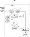
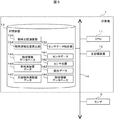
以下、実施形態について、図面を参照しながら説明する。本実施形態は、物流倉庫などの物品を対象とした物体の3次元物体認識システムである。図1は、3次元物体認識システムの機能ブロック図である。図1を用いて、本実施形態の概略を説明する。移動機構2によりセンサ3を移動させ、センサ3は移動しながらセンサデータ141を順次取得する。センサ3は、対象物までの距離を測定する距離センサである。
Hereinafter, embodiments will be described with reference to the drawings. The present embodiment is a three-dimensional object recognition system for an object intended for an article such as a distribution warehouse. FIG. 1 is a functional block diagram of a three-dimensional object recognition system. The outline of the present embodiment will be described with reference to FIG. The
センサデータ統合部132では、センサ3からのセンサデータ141とセンサ位置142とを入力とし、センサ位置142に応じてセンサデータ141を3次元空間内にプロットすることによりセンサデータ141を統合し、統合データ143を出力する。
The sensor
物体比較演算部133では、物体の3次元形状をあらわす統合データ143、予め物体情報データベース144に登録されている物体の種別に対応した形状や属性、及び予め物体配置データベース145に登録されている物体の積み方(積み付けパタン)を入力とし、実際に計測された統合データ143と予めデータベース143及び144に登録されているデータとを比較することにより、実際どのような配置になっているか認識し、物体実配置データ146を出力する。
In the object
物体領域位置算出部134では、物体の実配置データ146と、その物体をセンシングした時のセンサ位置142とを入力とし、物体の実配置データ146が3次元空間内のどこにあるか算出し、物体の3次元空間内の配置を表す大域物体実配置データ147を出力する。
The object region
なお、統合データ143とセンサ位置142とから、統合データ143の3次元空間(後述する大域座標系)における対応位置を先に決定し、大域座標系において物体比較演算部133を実行してもよい。
Note that the corresponding position in the three-dimensional space (global coordinate system described later) of the integrated
図1を用いた概略説明の中の、センサ3、センサ位置142及び統合データ143について説明する。
The
センサ3について図4(a)を用いて説明する。計測位置(x,y,z)にあるセンサ3が正対する方向が計測の方向(α,β,γ)である。センサ3は、ある面上を所定の角度(たとえば、1°)ごとに障害物や物体などの対象物までの距離と角度とを(L,θ)として出力する。言い換えると、センサ3は、ある面上を所定の角度ごとに障害物や物体などの対象物をスキャンすることになる。図4(a)では、センサ3の計測範囲を計測の方向(α,β,γ)を中心に−90°〜+90°の180°として示してある。センサ3が出力する角度θは、計測の方向(α,β,γ)とセンシングしている方向とがなす角度である。x−y平面を移動する移動機構2に搭載されるセンサ3の典型例は、移動機構2の所定の高さ、所定の計測方向にセンサ3が搭載され、z軸に平行(x−y平面に直交)にスキャンするように搭載する。この場合は、計測位置の高さzと計測の方向の仰角ベクトルγは一定となる。後述する距離センサ3の位置・姿勢データとは、計測位置(x,y,z)と計測の方向(α,β,γ)との組のデータである。
The
センサ位置142について説明する。移動機構2に搭載されたセンサ3の位置を認識するためには、移動機構2が移動する領域を表す地図データを参照して、ある基準位置からの、移動機構2の車輪の回転数の累積及び左右輪の回転数の累積の差より移動距離及び回転角度を求め、センサ3の現在の位置・姿勢を推定する方法がある。
The
ここでは、さらに移動機構2が移動する領域を表す地図データが無い場合の、センサ3の位置・姿勢を推定する方法を、図2及び図3を用いて説明する。地図データが無いので、地図を作成しながら、センサ3の現在の位置・姿勢を推定する。作成する地図を環境地図と呼ぶ。
Here, a method for estimating the position / posture of the
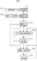
図2は、移動機構2とその移動機構2に搭載したセンサ3(ここでは環境計測用の距離センサとして機能)とを接続した計算機1の機能ブロックを示す図である。移動機構2の位置・姿勢を推定するために、センサ3は、スキャン面がx−y平面と平行になるように搭載する。移動制御部701から、移動機構2の行き先を指示することにより、移動機構2が移動する。距離データ取得部702では、センサ3を制御することにより、センサ3から距離データ710を取得する。ここでの距離データ710は、センサ3のある位置における計測範囲をスキャンしたデータ(L,θ)の集合である。
FIG. 2 is a diagram showing functional blocks of the
センサ位置・姿勢推定部703では、距離データ710、センサ位置姿勢データ711、及びそれまでに作成した環境地図712を入力として、新たに距離データ710を得た位置のセンサ3の位置・姿勢データ711を推定する。推定された位置・姿勢データ711は、環境地図712の座標空間における計測位置(x,y,z)と計測の方向(α,β,γ)との組として得られる。距離データ統合部704では、センサ位置・姿勢データ711、距離データ710、及びそれまでに作成した環境地図712を入力として、環境地図712にデータを追加更新する。
The sensor position /
移動機構位置算出部703および距離データ統合部704の処理には、これら二つの計算を同時に実行するSLAM (Simultaneous Localization And Mapping)技術を用いる。具体的には、距離データ710と、それまでに作成した環境地図712とをマッチングすることで、センサ3の環境地図712上の位置を求め、これに基づき環境地図712を逐次更新していく。
The processing of the movement mechanism
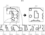
図2で説明した環境地図712の作成を、図3を用いて説明する。センサ3は、移動する位置ごとに710−1、710−2、710−3、・・・のような距離データ710を得る。センサ3のスキャン面がx−y平面と平行であり、センサ3はx−y平面と平行に移動するため、環境地図712は、x−y平面の2次元の地図として得られる。距離データ710から、710−1に示すように対象物(物体や障害物)の輪郭(図の実線。厳密には後述するように点の集合。)が得られる。距離データ710−1に710−2の対象物の輪郭がマッチングする部分を重ね合わせ、環境地図712を得、さらに距離データ710−1と710−2とにより作成した環境地図712に710−3のマッチングする部分を重ね合わせ、環境地図712を更新する。このような処理を繰り返すことにより環境地図712を作成する。一方、前回の距離データ710を取得した位置・姿勢データ711を参照して、逐次更新される環境地図712と距離データ710とのマッチングにより、センサ3の環境地図712上の2次元位置を推定することができる。さらに、センサ3が設置されている高さを追加することにより、3次元センサ位置142が求められる。
The creation of the
以上では、センサ3が環境計測用の距離センサとして機能することを前提として説明したが、後述する対象物までの距離、角度を計測する機能としての物体計測用センサを用いても良い。ただし、環境計測時と物体計測時のセンサ3のスキャン面が異なるため、図19で後述するように、環境測定用の距離センサ3aと物体計測用の距離センサ3bとを分けて計測するのが望ましい。
The above description is based on the assumption that the
次に、統合データ143について図4を用いて説明する。図4(a)に示すように、センサ3を用いて計測した、物体計測データとしての距離データ(L,θ)(物体や障害物などの計測の対象物までの距離、角度)とセンサ3の位置・姿勢データ(計測位置(x,y,z)と向き(α,β,γ)の組)とより、対象物の位置の3次元座標値(x1,y1,z1)を求める。センサ3を移動しながら距離データを計測するので、移動に伴って異なる位置で取得した距離データが、図4(b)に示すように、点の集まりとして得られる。それらの距離データを、同一座標系(たとえば、環境地図と同じ座標系)に変換し、纏めた、3次元空間における点の集合を、図4(c)に示すように、統合データ143と呼ぶ。統合データ143は、以上の説明から明らかなように、センサ3が測定した物体や障害物などの対象物までの距離と角度とからなる点の集合(点群)であるので、センサ3から見える対象物の輪郭(3次元凹凸)を表す。
Next, the
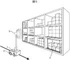
図5は、本実施形態の3次元物体認識システムを物流倉庫の棚卸しに適用した構成例である。本システムは、空間(物流倉庫の棚段)内に配置された物品4の棚卸しを対象とし、物品4の存否を認識する計算機1、移動機構2、センサ3により構成される。図5では、計算機1及びセンサ3は移動機構2に搭載されているが、計算機1を移動機構2に搭載せずに、計算機1と移動機構2及びセンサ3とを無線通信により接続した構成でも良い。
FIG. 5 is a configuration example in which the three-dimensional object recognition system of the present embodiment is applied to an inventory in a distribution warehouse. This system is intended for inventory of
移動機構2は、前述のようにセンサ3により計測した自らの位置・姿勢を計算機1によって推定することができるので、センサ3を移動させるものであれば、手動による台車などでも良いが、棚卸しに要する時間を短くするためには計算機1から移動を制御できる台車が望ましい。なお、高さ方向に多くの棚段を持つ倉庫のような場合は、棚段上の物品4の輪郭が得られるように、センサ3の高さ方向(z軸方向)の位置及び/又は計測の方向を可変にできる機構を移動機構2が備えることが望ましい。
Since the moving
センサ3は、物品までの距離を測定するレーザ距離センサである。物流倉庫にあっては、物品の種別を判別するために、物品の画像を取得するカメラ、ICタグを無線で読み取るRFIDリーダ、バーコードを読み取るバーコードリーダ等を備えていても良い。本実施形態では、物品の種別に対応した,梱包用の箱の形状や属性は、対象の物体の形状や属性として物体情報データベース144に登録されている。入庫後に物品を判別しても良いが、本実施形態では入庫時に、物品の種別に応じて、物品を配置する棚段などを含めたデータを物体情報データベース144に登録しておく。
The
図6は、本実施形態の3次元物体認識システムのハードウェア構成例を示す図である。計算機1は、CPU11、主記憶装置(メモリ)12、ハードディスク等の記憶装置13、及び、それらの構成要素を相互に接続するバス14とからなる。又、バス14を介して、CPU11の制御により動作するセンサ3が接続される。また、バス14には、必要に応じて通信制御装置や入出力装置が接続される。
FIG. 6 is a diagram illustrating a hardware configuration example of the three-dimensional object recognition system of the present embodiment. The
記憶装置13は、センサデータ統合部132、物体比較演算部133及び物体領域位置算出部134の各処理部のプログラムを格納する。これらのプログラムは主記憶装置12にロードされ、CPU11によって、それらの処理が実行される。
The
センサデータ統合部132は、センサデータ141とセンサ位置142を入力とし、3次元空間内にセンサ情報をプロットし、統合データ143を得る。再度、図4を用いて説明すると、センサ3が測定した、時刻tiにおける距離データ(距離L、角度θ)(図4(a))の点列を、移動機構2によってセンサ3が移動している時刻t1〜tnに亘って同一3次元空間内に点列でプロットすることによって(図4(b))、物体表面の形状を表す点群による統合データ143を作成する(図4(c))。統合データ143が作成される3次元空間の座標系は、後述する局所座標系又は大域座標系である。
The sensor
物体比較演算部133は、実測値である統合データ143と、物体の形状や属性を表す物体情報データベース144及び物体の配置を表す物体配置データベース145の内容とを比較することにより(物体情報データベース144及び物体の配置を表す物体配置データベース145の内容とから、物体のモデル及びその配置を想定し、想定した物体のモデル及び配置と統合データ143と比較することにより)、実際に物体がどのように配置されているかを示す、物体実配置データ146を出力する。物体実配置データ146は、物体種別ごとにどのような配置であるかを示すデータであるので、物体種別ごとに異なる座標系を用いることができる。物流倉庫の多くは、物品の入出庫のための通路の両側に棚段が設備されている。センサ3のこの通路を移動するので、両側の棚段に対するセンサ3の計測方向は反対側(180度異なる)になるので、物体種別ごとに異なる座標系を用いることにより、センサ位置と棚段上の物品との相対関係から物体実配置データ146を得ることができる。このような物体種別ごとに異なる座標系を局所座標系と呼ぶ。物体比較演算部133の詳細は後述する。
The object
物体領域位置算出部134は、物体実配置データ146と物体を計測したときのセンサ位置142より、計測した物体が広大な倉庫等の3次元空間内のどこに配置されているかを示す、大域物体実配置データ147を出力する。物体実配置データ146が局所座標系で表現されている場合、物流倉庫における位置は統一した座標系で表現する必要がある。これを大域座標系と呼び、各物体実配置データ146を表現している局所座標系から座標変換することにより大域物体実配置データ147を得る。
The object area
センサデータ141は、既に説明したセンサ3にて取得した距離データである。
The
センサ位置142は、たとえば図2及び図3を用いて説明した、センサデータ141を取得したときの位置を表すデータであり、時刻tiにおけるセンサデータ141である距離データ(距離L、角度θ)と対応付けて格納される。センサ位置142は、前述のように、センサ3の3次元空間内における位置、姿勢である。
The
統合データ143は、図4を用いて既に説明したとおりである。
The
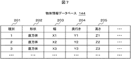
物体情報データベース144は、物体の属性を格納したものである。図7は、物体情報データベース144のデータ例を示す図である。物体情報データベース144には、物体の属性が格納されており、物体の種別201、形状(直方体、円柱、三角錐など)202、サイズとして直方体の場合は幅203、奥行き204、高さ205、などのデータが格納されている。本実施形態を適用する物流倉庫においては、棚卸しの他の入出庫管理などにも物体情報データベース144が利用されるので、重量、バーコードやRFIDによるID番号、物品画像、ロゴ等が格納されている場合もある。また、図7には図示していないが、物体の種別201に応じて予め定めた棚段を特定する情報(棚段番号など)も格納されている。さらに、後述するように物体の種別201に対応する各種パラメータを格納しておいても良い。
The
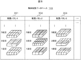
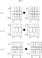
物体配置データベース145は、物体の種別や形状などに応じて予め定められた配置を格納したものである。図8は、物体配置データベース145のデータ例を示す図である。物体配置データベース145には、物体の配置パタン(積み付けパタン)を示すデータが格納されている。物体の形状やサイズにより、積み付け効率がよく荷崩れしにくいような配置パタンがある。例えば、配置パタン1(301)は、同じ段にある物体の向きは同一であり、段によって物体の向きが異なるパタンである。配置パタン2(302)は、同じ段にある物品の向きは同一であり、段によって物品の向きが異なり、かつ、ある位置に所定の隙間があるパタンである。配置パタン3(303)は、同じ段に異なる向きの物品が混在しているパタンである。配置パタンは、物体の種別に対応している。物流倉庫にあっては、物品としては同じであっても、物体としての梱包する箱の形状やサイズ、さらには重心位置が異なることがある。このような場合は、物体の種別が異なるものとする。
The
本実施形態では、物体の種別に応じて物体の形状や配置パタンが物体情報データベース144及び物体配置データベース145に格納されている。物流倉庫においては、物品の入出庫数の急変などにより、ある物品が所定の棚段以外に配置される場合がある。このような場合、物体の種別の識別、すなわち物体情報データベース144及び物体配置データベース145の内容の更新は、人手による外部からの入力によってもよいし、RFIDリーダやバーコードリーダにより読み取った物品IDやカメラで撮影した物体画像などに基づいても良い。
In the present embodiment, the object shape and the arrangement pattern are stored in the
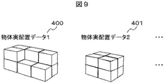
物体実配置データ146は、物体の実際の配置を示す。図9は、物体実配置データの例を示す図である。物体実配置データは、図9に示すように物体の種別に応じて、物体配置データベース145に格納されている配置パタンを参照して、センサ3による実計測データ(距離データ)から得た統合データに基づいて、実際の物体の配置パタンを示すデータである。図9に、ある種別の物体の物体実配置データ1(400)と他の種別の物体の物体実配置データ2(401)を示す。ここで、物体実配置データ1(400)及び物体実配置データ2(401)の各々の座標系(原点及びx軸、y軸、z軸の各方向)は前述のように局所座標系として異なっていても良い。
The actual
物流倉庫では、倉庫内に複数の棚段が並び、物体の種別ごとに棚段を割当てている場合、種別毎の物品(物体)を搭載したパレットが同じ棚段に置かれる場合などがある。前者の場合には物体の種別に対応した棚段ごとに物体実配置データがあり、後者の場合にはパレットごとに物体実配置データがある。棚段やパレット上の物品の実配置がわかれば、自動的に物品の個数もカウントできるが、物品を配置を認識するごとに物品の個数をカウントする処理について後述する。 In a distribution warehouse, when a plurality of shelves are arranged in the warehouse and shelves are allocated for each type of object, a pallet carrying articles (objects) for each type may be placed on the same shelf. In the former case, there is actual object placement data for each shelf corresponding to the type of object, and in the latter case, there is actual object placement data for each pallet. If the actual arrangement of articles on a shelf or pallet is known, the number of articles can be automatically counted. Processing for counting the number of articles every time the arrangement of articles is recognized will be described later.
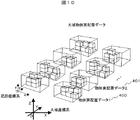
大域物体実配置データ147は、物体の3次元空間内における配置を示す。図10は、大域物体実配置データの例を示す図である。大域物体実配置データは、物体の種別に応じた局所座標系で表した物体実配置データを3次元空間の座標系である大域座標系に変換した、物体が3次元空間内のどこにあるのかを示すデータであり、図示するように、複数の物体の種別に応じた実配置データを、3次元空間内の位置に応じて配置したデータである。物流倉庫では、物体実配置データ146はパレットまたは棚段上にどのように物体が配置されているかを示すデータであるが、大域物体実配置データ147は、そのパレットや棚段の、3次元空間である倉庫内での物体の実配置を示す。
The global object
なお、局所、大域の2階層に限らず、適用対象により3階層、4階層のような多階層の座標系を用い、座標変換を繰り返し、物体配置を求めても良い。逆に、常に大域座標系を用いて物体実配置を定め、座標系に階層を持たせなくても良い。 It should be noted that the object arrangement may be obtained by repeating coordinate transformation using a multi-layer coordinate system such as three layers or four layers depending on the application target, not limited to the local and global two layers. On the contrary, it is not always necessary to determine the actual object arrangement using the global coordinate system and to have a hierarchy in the coordinate system.
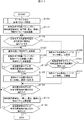
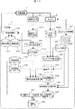
図11は、物体比較演算部133の処理フローチャートである。ここで説明する物体比較とは、統合データ143内に設定した物体設置領域(後述)内に、その領域に存在する可能性がある物体の3次元モデル(以下、物体モデル)を物体配置データベース145の配置パタンに従って仮置き(仮設置)し、物体モデル表面の点群密度により物体の有無(存否)を判断する。ここでは物体の形状は、物流分野の典型的な物品形状である直方体とし、物体配置データベース145の配置パタンに従って規則正しく並んでいるものとし、正面から見てカウント可能であるケース(正面から見えない位置にある物体は全て存在し欠損することはない)を対象として説明する。正面から見てとは、センサ3が計測した手前(センサ3側)から見ての意である。物流倉庫の棚段における物品の取り出しは、上から且つ手前からが通常である。したがって、手前(正面)から見えない位置にある物体(手前の物体により、センサ3により輪郭が捉えられない物体)は欠損していない。
FIG. 11 is a process flowchart of the object
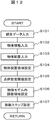
まず、各種データを入力したり、各種パラメータを設定したりする(S100)。図12に、各種パラメータの設定処理のフローチャートを示す。センサデータ141を統合した統合データ143を入力する(S101)。統合データ143の座標系は、以下に示す物体設置領域などの座標系とが異なる局所座標系の場合があり、異なるの場合はいずれかのデータを座標変換する。物体の種別に対応した、物体の形状、物体のサイズなどを示す物体情報を物体情報データベース144から入力(S102)し、物体の配置パタン物体の配置パタンを物体配置データベース145から入力する(S103)。
First, various data are input and various parameters are set (S100). FIG. 12 shows a flowchart of various parameter setting processing. The
次に、入力された統合データ143の中の、対象の種別の物体が設置される場所(物体設置領域)を設定する(S104)。設定される物体設置領域は、例えば棚上に物体が設置されるときは、その空間領域が棚の幅、奥行き及び高さにより表現される。物体設置領域は、たとえば図7の物体情報データベース144で説明したように、物体の種別に対応して棚段番号が特定されるので、棚段番号に対応した空間領域のサイズを予め計算機1に格納しておく。空間領域を大域座標系で表現して計算機1に格納している場合は、空間領域を表す座標値から、その幅、奥行き及び高さを求めるか、又は空間領域を表す座標値と統合データ143を表す座標値とのいずれかを座標変換し、座標系を合わせる。また前述したようにセンサ3により、棚段やパレットの輪郭も物体の輪郭と同様に計測されるので、統合データ143の中から棚段やパレットを認識する場合は、座標系は一致しているので、座標変換などは不要である。
Next, a place (object installation area) where an object of the target type is installed is set in the input integrated data 143 (S104). For example, when an object is placed on a shelf, the space area is represented by the width, depth, and height of the shelf. For example, as described in the
物体の有無を判断するための点群密度の閾値を設定し(S105)、物体モデル内のどの領域において点群密度を調べるかを指定する物体モデル表面の調査領域を設定し(S106)、物体モデルを点群データに当てはまる場所を探す際の物体モデルの移動幅を示す移動ステップを設定する(S107)。点群密度の閾値、物体モデルの調査領域及び物体モデルの移動ステップなども、他のパラメータと同様に物体の種別に対応して予め計算機1に格納しておく。これらは、物体情報データベース144の項目として格納しておいても良い。点群密度の閾値、物体モデルの調査領域及び物体モデルの移動ステップについては、これらを用いる処理の説明と共に後述する。
A threshold value of the point cloud density for determining the presence or absence of an object is set (S105), an investigation area on the surface of the object model for designating in which area in the object model the point cloud density is examined is set (S106), and the object A movement step indicating the movement width of the object model when searching for a place where the model applies to the point cloud data is set (S107). The threshold value of the point cloud density, the investigation area of the object model, the movement step of the object model, and the like are stored in the
図11のフローチャートは、物体の種別一つに対応した処理を示しているので、図12のパラメータの設定処理も物体の種別対応となる。物流倉庫にある多くの物品に関して処理を繰り返す場合は、たとえば物体情報データベース144の種別201を順次切り替えて図11に示すフローチャートの処理を実行する。
Since the flowchart in FIG. 11 shows processing corresponding to one object type, the parameter setting processing in FIG. 12 also corresponds to the object type. When the processing is repeated for many articles in the distribution warehouse, for example, the
図11の説明に戻る。物体形状や配置パタンに従い、設定した物体設置領域の、最下段、最右、最前(最も手前)に物体モデル1つを仮設置する(S110)。物体モデルは、たとえば物体の種別が1であるとき、図7の物体情報データベース144から、その物体は幅X1、奥行きY1、高さZ1の直方体である。
Returning to the description of FIG. According to the object shape and the arrangement pattern, one object model is temporarily installed in the lowermost, rightmost and foremost (frontmost) of the set object installation area (S110). For example, when the object type is 1, the object model is a rectangular parallelepiped having a width X1, a depth Y1, and a height Z1 from the
仮設置した物体モデルの調査領域の点群密度が設定した閾値を越えているかを判断する(S115)。物体モデルの形状が直方体であるとき、直方体の手前正面から奥行き方向に奥行きの例えば1/3の調査領域にある、点群で表されている統合データ143の点の個数をカウントし、点の数が設定した閾値、例えば100個を超えているかどうかを判断する。統合データ143は、図4(c)に示したように、存在する物体は少なくとも手前正面の長方形部分が見え、配置によっては(センサ3の計測方向によっては)、奥行き方向が見える一方の側面及び/又は上面の長方形部分が見える。統合データ143は、物体の輪郭を表していることから、直方体の場合には、たとえば手前正面と側面との辺で距離データ(点群)が変化する。この変化部分を調査領域に含むようにする。円錐形の物体のような場合は、頂点を含む局面の点群を含むように調査領域を設定することが望ましい。また点群密度として設定する閾値は、移動機構2の移動速度や距離データの計測間隔に応じて設定する。逆に言えば、設定する閾値によって物体の存在を認識できる点群密度が得られるように、移動機構2の移動速度やセンサ3による距離データの計測間隔を制御する。
It is determined whether the point cloud density in the investigation area of the temporarily installed object model exceeds a set threshold (S115). When the shape of the object model is a rectangular parallelepiped, the number of points of the
閾値を越えているならば、物体モデルを仮設置した位置に物体モデルに対応する物体があると判断し、仮設置していた物体モデルを仮設置した位置に設置し、物体の個数をカウントする(S120)。個数をカウントするカウンタは、説明を省略したが、パラメータ設定(S100)の一環として初期化しておく。設置した物体モデルの奥に、物体モデルを仮設置する(S125)。仮設置した物体モデルの少なくとも一部が、物体設置領域の最奥限を超えたかを判断する(仮設置した物体モデルが物体設置領域の奥からはみ出したかを判断する)(S130)。最奥限を超えていなければ、物体モデルを仮設置した位置に物体モデルに対応する物体があるので、S120に戻り、物体モデルを設置する。S120及びS125の処理を繰り返すことにより、センサ3により輪郭が捉えられない、奥側にある物体も認識することができ、物体モデルを設置することができる。以上の繰返しにより、ある段のある位置の奥行き方向1列にある物体の存否を認識し、存在する物体の個数をカウントできる。
If the threshold is exceeded, it is determined that there is an object corresponding to the object model at the position where the object model is temporarily installed, the object model that was temporarily installed is installed at the temporarily installed position, and the number of objects is counted. (S120). Although the description of the counter for counting the number is omitted, it is initialized as part of the parameter setting (S100). The object model is temporarily installed in the back of the installed object model (S125). It is determined whether at least a part of the temporarily installed object model exceeds the innermost limit of the object installation area (determining whether the temporarily installed object model protrudes from the back of the object installation area) (S130). If the maximum depth is not exceeded, there is an object corresponding to the object model at the position where the object model is temporarily installed, so the process returns to S120 and the object model is installed. By repeating the processing of S120 and S125, it is possible to recognize an object on the back side whose contour is not captured by the
仮設置した物体モデルの少なくとも一部が、物体設置領域の最奥限を超えたならば、物体モデルを幅の長さ分左に移動し、その最前に仮設置する(S135)。可設置した物体モデルの少なくとも一部が物体設置領域の最左限(左端)を超えたかを判断し(S140)、超えていなければ、物体モデルを仮設置した位置から奥行き方向の1列の物体の存否を調べるために、S115へ戻る。 If at least a part of the temporarily installed object model exceeds the innermost limit of the object installation area, the object model is moved to the left by the width and temporarily installed in front of it (S135). It is determined whether at least a part of the object model that has been installed exceeds the leftmost limit (left end) of the object installation area (S140). If not, one row of objects in the depth direction from the position where the object model was temporarily installed In step S115, the process returns to step S115.
仮設置した物体モデルの少なくとも一部が物体設置領域の最左限を超えたならば、物体配置データベース145から入力した配置パタンを参照して、可設置した物体モデルの段より一段上の最右、最前に物体モデルを仮設置する(S145)。なお、図8に示す物体は位置データベース145の配置パタン1(301)や配置パタン2(302)に示すように、段により物体の向きが異なる場合は、S145で物体モデルの向きを変えて仮設置する。仮設置した物体モデルの少なくとも一部が物体設置領域の最上限を超えたかを判断し(S150)、超えていなければ、物体モデルを仮設置した位置から奥行き方向の1列の物体の存否を調べるために、S115へ戻る。超えていれば、一連の処理を終了する。
If at least a part of the temporarily installed object model exceeds the leftmost limit of the object installation area, the arrangement pattern input from the
次に、仮設置した物体モデルの調査領域の点群密度が設定した閾値を越えていない場合について説明する閾値を越えていない場合は、物体モデルを仮設置した位置に物体モデルに対応する物体がないと判断し(S115)、物体モデルを、S107で設定した移動ステップ分、奥に移動し、物体モデルを仮設置する(S155)。奥行き方向の移動ステップは、物体設置領域の奥行き方向に所定の位置からずれて置かれている物体の存在を認識するために用いる。仮設置した物体モデルの少なくとも一部が、物体設置領域の最奥限を超えたかを判断する(S160)。最奥限を超えていなければ、物体モデルを仮設置した位置に物体モデルに対応する物体があるかどうかを調べるために、S115に戻る。 Next, when the point cloud density of the investigation area of the temporarily installed object model does not exceed the set threshold, the object corresponding to the object model is located at the position where the object model is temporarily installed. It is determined that there is not (S115), the object model is moved to the back by the movement step set in S107, and the object model is temporarily installed (S155). The moving step in the depth direction is used for recognizing the presence of an object placed in a depth direction of the object installation area from a predetermined position. It is determined whether at least a part of the temporarily installed object model exceeds the innermost limit of the object installation area (S160). If it does not exceed the innermost limit, the process returns to S115 to check whether there is an object corresponding to the object model at the position where the object model is temporarily installed.
仮設置した物体モデルの少なくとも一部が、物体設置領域の最奥限を超えたならば、物体モデルを、S107で設定した移動ステップ分、左に移動し、その最前に仮設置する(S165)。可設置した物体モデルの少なくとも一部が物体設置領域の最左限(左端)を超えたかを判断するために、S140へ処理を移す。 If at least a part of the temporarily installed object model exceeds the innermost limit of the object installation area, the object model is moved to the left by the movement step set in S107 and temporarily installed in front of it (S165). . In order to determine whether at least a part of the available object model exceeds the leftmost limit (left end) of the object installation area, the process proceeds to S140.
奥方向への移動ステップと左方向への移動ステップとは同じ値を用いてもよいし、それぞれ異なる値を用いてもよい。ただし、移動ステップが小さ過ぎると、計算機1の処理時間が長くなるので、物体及び物体設置領域のサイズに応じて決定することが望ましい。たとえば、最下段、最右、最前に物体が存在しないとき、最前から奥行き方向に移動ステップ分ずつ刻んでいくと、(物体の奥行きの長さ)/(奥行き方向に移動ステップ)の回数は、S115において物体の存在を認識できないことになる。
The same value may be used for the backward movement step and the leftward movement step, or different values may be used. However, if the moving step is too small, the processing time of the
センサ3が計測した距離データに基づく統合データ143は物体表面の凹凸(輪郭)を表す座標値である。したがって、物体モデルを仮設置したとき、物体の輪郭を表す座標値と物体モデルの座標値は必ずしも一致しない。僅かな差であっても一致しない場合には、S115で点群密度が閾値を超えていないと判断する可能性がある。そこで、座標値の一致から点群を検知するのではなく、物体モデルの座標値に許容幅を設け、その許容幅に含まれる点群を検知するようにする。換言すると、物体モデルを仮設置した位置を中心として前後(奥行き方向)、左右(幅方向)に許容幅にわたって移動させて、その間に検知した点群の数を閾値と比較する。
The
この許容幅は移動ステップの長さ以上であることが望ましい。たとえば、奥行き方向の移動ステップを4cmとしたとき、物体モデルを仮設置した位置を中心に−2cm〜+2cmの4cmを許容幅とすれば、移動ステップ分の移動に伴って、検知されるべき点群の検知漏れを防ぐことができる。 This allowable width is preferably equal to or greater than the length of the moving step. For example, if the moving step in the depth direction is 4 cm, if the allowable width is −2 cm to +2 cm around the position where the object model is temporarily installed, the point that should be detected along with the movement of the moving step It is possible to prevent omission of detection of the group.
以上により、S120で物体モデルを設置した位置に物体があることを認識でき、且つその数をカウントすることができる。 As described above, it can be recognized that there is an object at the position where the object model is installed in S120, and the number of the objects can be counted.
なお、以上の説明では、物体モデルを、手前から奥、右から左、下から上、に向かって仮設置し、点群密度により物体の有無を調べたが、調べる順番はこれに限らず、左から右、上から下でも構わない。 In the above description, the object model is temporarily installed from the front to the back, from the right to the left, from the bottom to the top, and the presence or absence of the object is examined by the point cloud density, but the examination order is not limited to this, It can be left to right or top to bottom.
以上の処理によって、物体モデルを少しずつずらしながら点群データに当てはめるため、物体が理想の位置からずれていても実配置データを求めることができる。 With the above processing, the object model is applied to the point cloud data while being gradually shifted, so that the actual arrangement data can be obtained even if the object is shifted from the ideal position.
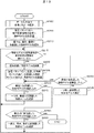
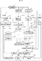
図13は、物体比較演算部の他の処理フローチャートである。ここで説明する物体比較は、統合データ143内の物体設置領域の全域に、物体の3次元モデル(物体モデル)を仮置き(仮設置)し、各物体モデルの点群密度により物体の有無を判断する。なお、物体の種別対応に処理を実行すること、正面から見えない位置にある物体は欠損していないこと、点群を検知するときの許容幅などに関しては、図11の処理フローチャートの説明と同様である。
FIG. 13 is another process flowchart of the object comparison calculation unit. In the object comparison described here, a three-dimensional model (object model) of an object is temporarily placed (temporary installation) over the entire object installation area in the
各種データの入力、及び各種パラメータの設定は、図12を用いて説明したとおりであるが(S100)、移動ステップ設定(S107)は必要ない。 The input of various data and the setting of various parameters are as described with reference to FIG. 12 (S100), but the movement step setting (S107) is not necessary.
物体配置データベース145から入力した、物体種別に対応した配置パタンを参照して、物体設置領域の全域に(物体が欠損せずに揃っている状態となるように)、物体モデルを仮設置する(S205)。最下段、最右、最前にある仮設置モデルを検証対象として選択する(S210)。選択した物体モデル内の調査領域の点群密度が閾値を越えているかどうかを判断し(S215)、閾値を超えている場合は、該当位置に物体モデルを設置する(S220)。S215における閾値を越えているかどうかを判断することを検証と呼ぶ。物体モデルを設置する際に、物体の数をカウントすることは図11の場合と同様である。配置パタンに従い、設置した物体モデルの奥に仮設置した物体モデルがあれば(物体モデルを設置した位置が最奥の設置位置でなければ)、仮設置した最奥の物体モデルに至るまで奥に向かって、物体モデルを設置する(S225)。この場合も、物体モデルの設置に応じて、物体の数をカウントする。なお、物体モデルの設置の仕方が配置パタンに依存するので、この点について後述する。
With reference to the arrangement pattern corresponding to the object type input from the
選択した物体モデルの調査領域の点群密度が閾値を越えていない場合、その物体モデルから見て物体設置領域の最奥に仮設置した物体モデルを検証したかを判断し(S230)、検証していなければ、一つ奥に仮設置した物体モデルを選択し(S235)、S215に戻る。 If the point cloud density in the investigation area of the selected object model does not exceed the threshold value, it is determined whether the object model temporarily installed at the innermost position of the object installation area as viewed from the object model has been verified (S230). If not, the object model temporarily installed in the back is selected (S235), and the process returns to S215.
S225の処理又はS230の判断により、奥行き方向の1列の処理が終了したならば、最左に仮設置した物体モデルを検証したかを判断し(S240)、検証してなければ、一つ左の最前に仮設置した物体モデルを選択し(S245)、S215へ戻る。最左に仮設置した物体モデルを検証したならば、その一段の物体モデルの検証が終わったことであるので、最上段に仮設置した物体モデルを検証したかを判断する(S250)。検証してなければ、一段上、最右、最前に仮設置した物体モデルを選択し(S255)、S215へ戻る。最上段に仮設置した物体モデルを検証したと判断したならば、物体設置領域内に仮設置した物体モデルの検証が終了したことであり、一連の処理を終了する。 If the processing in S225 or the determination in S230 completes the processing in one column in the depth direction, it is determined whether the object model temporarily installed at the leftmost is verified (S240). The object model temporarily installed before is selected (S245), and the process returns to S215. If the object model temporarily installed at the leftmost is verified, it means that the verification of the one-stage object model is completed, and it is determined whether the object model temporarily installed at the uppermost stage has been verified (S250). If not verified, the object model temporarily installed at the uppermost, rightmost, and frontmost is selected (S255), and the process returns to S215. If it is determined that the object model temporarily installed in the uppermost stage has been verified, it means that the verification of the object model temporarily installed in the object installation area has been completed, and the series of processing ends.
図14は、図13のS225における物体設置領域の奥行き方向への物体モデルの設置の仕方を説明する図である。ある一段について説明する。図中の「○」は物体があると判定し、物体モデルを設置した位置であり、「×」は物体がないと判定した位置であり、「・」は物体の有無(存否)をまだ検証していない、仮設置した物体モデルが設置されている位置を示す。 FIG. 14 is a diagram for explaining how to install an object model in the depth direction of the object installation area in S225 of FIG. A certain level will be described. “○” in the figure indicates that there is an object, the position where the object model is installed, “×” is the position where it is determined that there is no object, and “•” still verifies the presence or absence (existence) of the object The position where the temporarily installed object model is not installed is shown.
図14のケース1は、最前列の仮設置した物体モデルの検証において、右から3番目のみに物体があると判定された例である。一つ奥の列(2列目)を検証し、1列目右から3番目の物体モデルに接している位置に物体モデルを設置する。更に、奥の列(3列目)を検証し、2列目の物体モデルに接している位置に物体モデルを設置する。
図14のケース2は、2列目の真ん中に仮設置した物体モデルが、一列目の右の物体モデルに半分接している例である。背面(奥行き方向)に物体モデルを設置するために必要な接触割合を予め定める。例えば、その接触割合を2/3以上とした場合、2列目の真ん中に仮設置した物体モデルは接触部分が不足しているため、物体モデルを設置しない。3列目の右に仮設置した物体モデルは、2列目の右に設置した物体モデルに2/3接しているので、物体モデルを設置する。
図14のケース3は、1列目の右から1番目、2番目、4番目に物体があると判定された例である。2列目の右に仮設置された物体モデルは、1列目の右から1番目と2番目とに設置した二つの物体モデルに4/5接しているので、物体モデルを設置する。
図13に示した処理フローチャートによれば、物体種別に対応した配置パタンに従って、物体設置領域の全域に物体の3次元モデル当てはめ(物体モデルを仮設置し)、3次元モデルの点群密度で物体の有無を判断するため、図14を用いて説明した、物体の向きが段により異なるような複雑な配置パタンにも対応できる。 According to the processing flowchart shown in FIG. 13, according to the arrangement pattern corresponding to the object type, a 3D model is applied to the entire area of the object installation area (an object model is temporarily installed), and the object is displayed with the point cloud density of the 3D model. In order to determine the presence / absence of the object, it is possible to cope with a complicated arrangement pattern described with reference to FIG.
物体比較演算部133では、図11及び図13を用いて説明した処理を配置パタンに応じて選択的に実行することにより、物体の実配置データ146と物体の個数を得ることができるので、これらを計算機1は表示装置などに出力することができる。また、物流倉庫における棚卸しに適用する場合は、帳簿データとの比較データとして、物体の実配置データ146と物体の個数とを用いる。
The object
以上の物体比較演算部133の説明において、物体設置領域は物流倉庫における棚段のような、幅、高さ、奥行きのある直方体の領域を想定している。物流倉庫にあっては、特定の物品の入出庫個数の急激な変化により、ある棚段に複数種別の物品を、棚段をたとえば左右に分けて、又は物品を積み付ける段を異にして、積み付ける場合がある。このような場合は、各々の種別に対応した積み付け領域(段)を物体設置領域とする。
In the above description of the object
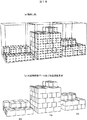
図15及び図16は、実データによる物体比較演算例である。センサ3による距離データを丸印で示してある。図15(a)は、統合データ143の一例である。図15(b)は、図12のS104にて設定された物体設置領域を示した図である。図16(a)は、物体比較演算部133で、統合データに物体モデルを当てはめている様子を示した図である。図16(b)は、大域物体実配置データ147に物体個数を示した図である。
15 and 16 are examples of object comparison calculations based on actual data. The distance data obtained by the
図17は、移動機構が自律的に移動できるようにし(自らが、障害物などの環境を認識し、目的地までの移動経路を定めし、定めたいどう経路に従って移動できる)、物流倉庫などの物品の棚卸しデータベースを更新できるようにした棚卸しシステムの機能ブロック図である。 FIG. 17 shows that the movement mechanism can move autonomously (it can recognize the environment such as obstacles, determine the movement route to the destination, and move according to the desired route) It is a functional block diagram of the inventory system which enabled it to update the inventory database of goods.
移動機構2に、周辺環境の距離を測定する距離センサ3aと物体を測定するセンサ3bを搭載し、距離センサ3aでは現在の距離データ(周辺環境)1411を取得し、センサ3bでは、センシング対象の物体を計測したセンサデータ(物体)1412を取得する。
The moving
センサ位置推定部131では、現在の距離データ(周辺環境)1411と周辺環境の距離データを統合して事前に作成した環境地図148とをマッチングすることにより、距離センサ3aの環境地図148上の位置を算出し、センサ位置1421を出力する。センサ位置1421は、環境地図148上の2次元座標値(x,y)で表わされる。センサ位置1421は、移動機構2に距離センサ3aとセンサ3bとが搭載されているので、移動機構2、距離センサ3a、及びセンサ3bの環境地図148上の位置と言える。なお、環境地図作成方法は図2及び図3を用いて説明したとおりである。
In the sensor
移動制御部135では、センサ位置1421と環境地図148と予め環境地図148上に作成した移動経路147を入力し、現在位置を示すセンサ位置1421と移動経路147とを照合し、移動機構2の現在位置からの進行方向を決定し、決定した方向に移動機構2が移動するように制御する。
The
センシング制御部136では、センシングパラメータ149に従いセンサ3bを制御し、センサデータ(物体)1412を得る。センサ3bは、複数個備えてもよいし、複数種類備えてもよく、これらのデータを同時に取得してもよい。センシングパラメータ149には、例えばセンサ3bに距離センサのパラメータの一例として、センシング時の角度分解能、フレームレート、センシング距離などが含まれ、例えばセンサ3bにカメラを用いた場合、フレームレート、シャッタースピード、ホワイトバランス、絞り等が含まれ、例えばセンサ3bにRFIDリーダを用いた場合、通信距離、通信範囲などが含まれる。また、センサ3bがロボットアームの先端に取り付けられている場合、センサ自体の動作(移動、回転)をパラメータとして所持してもよい。
The
センサデータ統合部132では、移動機構2による移動経路147に従った移動が終了した後、又は移動経路147を移動中に、センサデータ(物体)1412と、センサデータ(物体)を取得したときのセンサの2次元位置1421と、予め記憶したセンサ3bのセンシング時の高さを示すセンサ高さ1422より、センサデータ(物体)1412を異地点で計測したデータを一つの座標系に統合し、統合データ143を出力する。
In the sensor
物体比較演算133から物体領域位置算出部134までの流れは、図1と同一である。
The flow from the
棚卸データ更新部137では、物体領域位置算出部134で出力した大域物体実配置データ147と、物体種別データを格納する物体情報データベース144とを入力とし、物体種別、物体位置、物体個数、物体実配置、等のデータが格納される棚卸データ150を更新する。
The inventory
図18は、図17に示した棚卸しシステムに、更に情報フィードバック機能を備えた棚卸しシステムの機能ブロック図である。図17に示した流れに、移動経路設定部137とセンシングパラメータ設定部138が加わる。
FIG. 18 is a functional block diagram of an inventory system provided with an information feedback function in addition to the inventory system shown in FIG. A movement
移動経路設定部137では、棚卸データ150に含まれる物体位置情報をもとに、次回棚卸時の最適経路を設定する。例えば、棚卸したい物体を複数指定しそこを通る最適な経路を作成してもよいし、物体のある領域のみを棚卸するような経路を指定してもよい。図16に経路例を後述する。また、移動機構2の移動速度を同時に設定してもよい。例えば、移動機構2をセンシングの必要な場所はゆっくり移動させ、移動するのみの場所は高速に移動させる。
The movement
センシングパラメータ設定部138では、センシング対象となる物体に応じたセンシングパラメータを設定する。例えば、センサ3bに距離センサを用いた場合、物体のサイズによって必要なセンシング精度が異なる。このため、サイズの大きい物体のある領域はセンシング時のフレームレートを落としたり解像度を下げたりし、サイズの小さい物体のある領域は、センシング時のフレームレートを上げたり解像度を上げたりする。また、棚卸し場所の明るさに応じてカメラの色調整を行ったり、暗い場所での棚卸しが必要な場合は、カメラではなく、赤外線カメラやレーザセンサの使用に切り替えたりする。また更に、物体の形状に応じて観察する場所を変える、例えば正面からだけではなく、センサ3bをロボットアーム先端に取り付け、物体上面からセンシングするためのセンサ動作をパラメータとしてもよい。
The sensing
このように、物体の状況に応じて、移動経路やセンシングパラメータを変更することにより、例えば、計測の必要な場所のみに立ち寄り、計測することにより、移動距離や移動と計測の時間を短縮すること、計測対象によりセンシング方法を変えることにより、対象物を認識するのに十分な計測パラメータ、且つ、少ないデータ量や時間で計測すること、及び/又はセンサを動作自由度の高いロボットアームに取りつけてさまざまな角度から計測を行い、認識に必要な情報量を増やすことにより認識の精度を上げるなど、より最適な棚卸を実現することができる。 In this way, by changing the movement route and sensing parameters according to the state of the object, for example, by stopping and measuring only at the place where measurement is required, the movement distance and the time for movement and measurement can be shortened. By changing the sensing method according to the measurement object, measurement parameters can be measured with a sufficient amount of data and time to recognize the object, and / or the sensor can be attached to a robot arm with a high degree of freedom of movement. By taking measurements from various angles and increasing the amount of information necessary for recognition, it is possible to achieve more optimal inventory, such as increasing the accuracy of recognition.
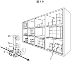
図19は、図17に示した棚卸しシステムのシステム構成例を示す図である。空間内に設置された物品4、自律移動機能を備えた移動機構2、周辺環境を測定する距離センサ3a、物品4の状態を測定するセンサ3b、センサ3a及び3bを用いて物品4の自動棚卸しを行い且つ移動機構の動作制御を行う計算機1により構成される。
FIG. 19 is a diagram illustrating a system configuration example of the inventory system illustrated in FIG. 17. The
図20は、自律移動による自動棚卸し時の経路例である。図20(a)は、すべての棚の物体を棚卸対象とするときの経路の一例であり、全ての棚卸対象棚610にある物品の棚卸する際の移動経路601を表わしている。
FIG. 20 is an example of a route at the time of automatic inventory by autonomous movement. FIG. 20A is an example of a path when objects on all shelves are to be inventoried, and represents a
図20(b)は、一部の棚の物体を棚卸するときの経路の一例であり、棚卸対象棚610と棚卸対象でない棚611とがあるときに棚卸する際の移動経路602を丸印内の数字603で表わしている。このように、棚卸の必要有無に応じて経路を設定することにより、効率的な棚卸ができる。
FIG. 20B is an example of a path for inventorying some of the objects on the shelf, and the
以上説明した実施形態によれば、センサを移動し、センサから取得したデータから作成する物体3次元形状と、データベースに格納されている物体属性(形状や積みつけパタンなど)とを比較することにより、物体の存否を認識し、物体の個数をカウントすることができる。 According to the embodiment described above, by moving the sensor and comparing the object three-dimensional shape created from the data acquired from the sensor with the object attributes (shape, stacking pattern, etc.) stored in the database. , The presence or absence of an object can be recognized and the number of objects can be counted.
また、このような3次元物体認識システムを用いることにより、荷物(物品)の倉庫内の配置を認識し、個数をカウントすることができる。 Further, by using such a three-dimensional object recognition system, it is possible to recognize the arrangement of luggage (articles) in a warehouse and to count the number.
1:計算機、2:移動機構、3:センサ、4:物品、132:センサデータ統合部、133:物体比較演算部、134:物体領域位置算出部、144:物体情報データベース、145:物体配置データベース。 1: computer, 2: moving mechanism, 3: sensor, 4: article, 132: sensor data integration unit, 133: object comparison calculation unit, 134: object region position calculation unit, 144: object information database, 145: object arrangement database .
Claims (16)
前記センサと接続し、前記物体の少なくとも形状を格納する物体情報データベース、
前記物体の配置パタンを格納する物体配置データベース、
前記移動機構による前記センサの移動に伴う前記センサからの、前記物体までの距離を計測したセンサデータと前記センサデータを得た前記センサの位置とを入力とし、前記センサの位置に応じて前記センサデータを3次元空間内に統合した、前記物体の輪郭を示す統合データを出力するセンサデータ統合部、及び
前記物体情報データベースに格納された前記形状から物体モデルを作成し、前記物体配置データベースに格納された前記物体の配置パタンを参照して、前記作成した物体モデルと前記統合データとを比較して前記物体の実配置を示す物体実配置データを出力する物体比較演算部を有する計算機とを設けたことを特徴とする3次元物体認識システム。 A sensor for measuring a distance to an object, a moving mechanism for moving the sensor,
An object information database connected to the sensor and storing at least the shape of the object;
An object placement database for storing the placement pattern of the object;
Sensor data obtained by measuring the distance from the sensor to the object accompanying the movement of the sensor by the moving mechanism and the position of the sensor from which the sensor data has been obtained are input, and the sensor according to the position of the sensor An object model is created from the shape stored in the object information database, and a sensor data integration unit that outputs integrated data indicating the outline of the object, which integrates data in a three-dimensional space, and stores the object model in the object arrangement database A computer having an object comparison calculation unit that compares the created object model with the integrated data and outputs object actual arrangement data indicating the actual arrangement of the object with reference to the object arrangement pattern A three-dimensional object recognition system.
前記センサと接続し、前記物品の少なくとも形状を格納する物体情報データベース、
前記物品の積み付けパタンを格納する物体配置データベース、
前記移動機構による前記センサの移動に伴う前記センサからの、前記物品までの距離を計測したセンサデータと前記センサデータを得た前記センサの位置とを入力とし、前記センサの位置に応じて前記センサデータを3次元空間内に統合した、前記物品の輪郭を示す統合データを出力するセンサデータ統合部、及び
前記物体情報データベースに格納された前記形状から物体モデルを作成し、前記物体配置データベースに格納された前記物品の配置パタンを参照して、前記作成した物体モデルと前記統合データとを比較して前記物品の実配置を示す物体実配置データを出力する物体比較演算部を有する計算機とを設けたことを特徴とする棚卸システム。 A sensor for measuring the distance to the article in the warehouse, a moving mechanism for moving the sensor,
An object information database connected to the sensor and storing at least the shape of the article;
An object placement database for storing a stacking pattern of the articles;
Sensor data obtained by measuring the distance from the sensor to the article accompanying the movement of the sensor by the moving mechanism and the position of the sensor from which the sensor data is obtained are input, and the sensor according to the position of the sensor An object model is created from the shape stored in the object information database, and a sensor data integration unit that outputs integrated data indicating the outline of the article, in which data is integrated in a three-dimensional space, and is stored in the object arrangement database And a computer having an object comparison operation unit that compares the created object model with the integrated data and outputs object actual arrangement data indicating the actual arrangement of the article with reference to the arranged pattern of the article. An inventory system characterized by that.
Priority Applications (2)
| Application Number | Priority Date | Filing Date | Title |
|---|---|---|---|
| JP2008184686A JP5259286B2 (en) | 2008-07-16 | 2008-07-16 | 3D object recognition system and inventory system using the same |
| US12/502,719 US8150658B2 (en) | 2008-07-16 | 2009-07-14 | Three-dimensional object recognition system and inventory system using the same |
Applications Claiming Priority (1)
| Application Number | Priority Date | Filing Date | Title |
|---|---|---|---|
| JP2008184686A JP5259286B2 (en) | 2008-07-16 | 2008-07-16 | 3D object recognition system and inventory system using the same |
Publications (2)
| Publication Number | Publication Date |
|---|---|
| JP2010023950A JP2010023950A (en) | 2010-02-04 |
| JP5259286B2 true JP5259286B2 (en) | 2013-08-07 |
Family
ID=41531193
Family Applications (1)
| Application Number | Title | Priority Date | Filing Date |
|---|---|---|---|
| JP2008184686A Expired - Fee Related JP5259286B2 (en) | 2008-07-16 | 2008-07-16 | 3D object recognition system and inventory system using the same |
Country Status (2)
| Country | Link |
|---|---|
| US (1) | US8150658B2 (en) |
| JP (1) | JP5259286B2 (en) |
Families Citing this family (89)
| Publication number | Priority date | Publication date | Assignee | Title |
|---|---|---|---|---|
| WO2009016614A2 (en) * | 2007-08-02 | 2009-02-05 | Emza Visual Sense Ltd. | Universal counting and measurement system |
| US8494909B2 (en) * | 2009-02-09 | 2013-07-23 | Datalogic ADC, Inc. | Automatic learning in a merchandise checkout system with visual recognition |
| JP5560794B2 (en) * | 2010-03-16 | 2014-07-30 | ソニー株式会社 | Control device, control method and program |
| JP5609302B2 (en) * | 2010-06-18 | 2014-10-22 | 富士通株式会社 | Contact definition device, contact definition program, and contact definition method |
| CN103459099B (en) * | 2011-01-28 | 2015-08-26 | 英塔茨科技公司 | Interact with a mobile telebot |
| JP2012162341A (en) * | 2011-02-04 | 2012-08-30 | Casio Computer Co Ltd | Code information reading device, article management system, and program |
| US9205886B1 (en) * | 2011-05-06 | 2015-12-08 | Google Inc. | Systems and methods for inventorying objects |
| US9367770B2 (en) * | 2011-08-30 | 2016-06-14 | Digimarc Corporation | Methods and arrangements for identifying objects |
| US9067744B2 (en) | 2011-10-17 | 2015-06-30 | Kabushiki Kaisha Yaskawa Denki | Robot system, robot, and sorted article manufacturing method |
| US20130120361A1 (en) * | 2011-11-16 | 2013-05-16 | Industrial Technology Research Institute | Spatial 3d interactive instrument |
| US9224184B2 (en) | 2012-10-21 | 2015-12-29 | Digimarc Corporation | Methods and arrangements for identifying objects |
| US9182812B2 (en) * | 2013-01-08 | 2015-11-10 | Ayotle | Virtual sensor systems and methods |
| US9111348B2 (en) | 2013-03-15 | 2015-08-18 | Toyota Motor Engineering & Manufacturing North America, Inc. | Computer-based method and system of dynamic category object recognition |
| JP6141782B2 (en) * | 2014-03-12 | 2017-06-07 | 株式会社豊田自動織機 | Method for updating map information in a linked system of automated guided vehicle and inventory management system |
| US9286538B1 (en) * | 2014-05-01 | 2016-03-15 | Hrl Laboratories, Llc | Adaptive 3D to 2D projection for different height slices and extraction of robust morphological features for 3D object recognition |
| US20150356666A1 (en) * | 2014-06-10 | 2015-12-10 | Hussmann Corporation | System and method for generating a virtual representation of a retail environment |
| US9548014B2 (en) * | 2014-08-04 | 2017-01-17 | Canon Kabushiki Kaisha | Information processing apparatus and information processing method |
| JP2016058043A (en) * | 2014-09-12 | 2016-04-21 | キヤノン株式会社 | Information processing apparatus, information processing method, and program |
| US9996738B2 (en) * | 2015-02-13 | 2018-06-12 | Swan Solutions, Inc. | System and method for controlling a terminal device |
| KR101708664B1 (en) * | 2015-02-16 | 2017-02-22 | 주식회사 이에스아이티 | System for tracking location and location engine for thereof and method for collecting location information thereof |
| US9367831B1 (en) | 2015-03-16 | 2016-06-14 | The Nielsen Company (Us), Llc | Methods and apparatus for inventory determinations using portable devices |
| CN107408199B (en) * | 2015-03-24 | 2021-09-10 | 科磊股份有限公司 | Method for classifying the shape of an object |
| JP6683917B2 (en) * | 2015-06-11 | 2020-04-22 | 株式会社デンソーエスアイ | Wireless tag management system |
| US9747512B2 (en) * | 2015-06-25 | 2017-08-29 | Toshiba Tec Kabushiki Kaisha | Article recognition apparatus and image processing method for article recognition apparatus |
| US20170091349A1 (en) * | 2015-09-24 | 2017-03-30 | Hcl Technologies Limited | System and method for facilitating optimization of space in a warehouse |
| EP3188089A1 (en) * | 2015-12-30 | 2017-07-05 | Fujitsu Limited | Inventory management for a quantified area |
| JP6781567B2 (en) * | 2016-04-01 | 2020-11-04 | 東芝テック株式会社 | Weighing device |
| JP6605711B2 (en) * | 2016-04-05 | 2019-11-13 | 株式会社日立物流 | Measuring system and measuring method |
| US10949797B2 (en) * | 2016-07-01 | 2021-03-16 | Invia Robotics, Inc. | Inventory management robots |
| MX372796B (en) * | 2016-08-04 | 2020-07-03 | Opex Corp | AUTOMATED STORAGE AND RETRIEVAL SYSTEM WITH DETECTOR TO DETECT PRODUCTS THAT EXTEND BEYOND THE DIMENSIONAL THRESHOLD. |
| CN107822400B (en) * | 2016-09-15 | 2020-12-15 | 东芝泰格有限公司 | Inventory management device, control method, and terminal device |
| US11042161B2 (en) | 2016-11-16 | 2021-06-22 | Symbol Technologies, Llc | Navigation control method and apparatus in a mobile automation system |
| JP6896401B2 (en) * | 2016-11-25 | 2021-06-30 | 東芝テック株式会社 | Article recognition device |
| JP6840530B2 (en) * | 2016-12-22 | 2021-03-10 | 東芝テック株式会社 | Image processing device and image processing method |
| JP7019295B2 (en) | 2017-01-20 | 2022-02-15 | 東芝テック株式会社 | Information gathering device and information gathering system |
| TWI634403B (en) * | 2017-01-26 | 2018-09-01 | 好樣科技有限公司 | Automatic cleaning machine and control method thereof |
| JP6880950B2 (en) * | 2017-04-05 | 2021-06-02 | 村田機械株式会社 | Depression detection device, transfer device, and recess detection method |
| AU2018261257B2 (en) | 2017-05-01 | 2020-10-08 | Symbol Technologies, Llc | Method and apparatus for object status detection |
| US11449059B2 (en) | 2017-05-01 | 2022-09-20 | Symbol Technologies, Llc | Obstacle detection for a mobile automation apparatus |
| WO2018204342A1 (en) | 2017-05-01 | 2018-11-08 | Symbol Technologies, Llc | Product status detection system |
| WO2018201423A1 (en) | 2017-05-05 | 2018-11-08 | Symbol Technologies, Llc | Method and apparatus for detecting and interpreting price label text |
| US10606828B2 (en) * | 2017-10-19 | 2020-03-31 | Jpmorgan Chase Bank, N.A. | Storage correlation engine |
| DE112018006071B4 (en) * | 2017-12-27 | 2025-08-21 | Panasonic Intellectual Property Management Co., Ltd. | FORM IDENTIFICATION DEVICE AND DELIVERY BOX |
| JP7016276B2 (en) * | 2018-03-05 | 2022-02-04 | 株式会社日立製作所 | Train position estimator |
| JP2019159493A (en) * | 2018-03-08 | 2019-09-19 | 東芝テック株式会社 | Reading system |
| JP7062507B2 (en) * | 2018-05-08 | 2022-05-16 | 東芝テック株式会社 | Article recognition device |
| DE102018116834A1 (en) * | 2018-07-11 | 2020-01-16 | Sick Ag | Automation system for a warehouse |
| US11506483B2 (en) | 2018-10-05 | 2022-11-22 | Zebra Technologies Corporation | Method, system and apparatus for support structure depth determination |
| US11010920B2 (en) * | 2018-10-05 | 2021-05-18 | Zebra Technologies Corporation | Method, system and apparatus for object detection in point clouds |
| US11090811B2 (en) | 2018-11-13 | 2021-08-17 | Zebra Technologies Corporation | Method and apparatus for labeling of support structures |
| US11416000B2 (en) | 2018-12-07 | 2022-08-16 | Zebra Technologies Corporation | Method and apparatus for navigational ray tracing |
| US11079240B2 (en) | 2018-12-07 | 2021-08-03 | Zebra Technologies Corporation | Method, system and apparatus for adaptive particle filter localization |
| EP3667230B1 (en) * | 2018-12-13 | 2021-06-23 | IVF Hartmann AG | Measuring system and method for inventory taking by means of 3d scan |
| US11126861B1 (en) | 2018-12-14 | 2021-09-21 | Digimarc Corporation | Ambient inventorying arrangements |
| JP7159033B2 (en) | 2018-12-21 | 2022-10-24 | 株式会社日立製作所 | 3D position/orientation recognition device and method |
| CA3028708C (en) | 2018-12-28 | 2025-12-09 | Zebra Technologies Corporation | Method, system and apparatus for dynamic loop closure in mapping trajectories |
| US11069081B1 (en) * | 2019-01-25 | 2021-07-20 | Google Llc | Location discovery |
| WO2020158970A1 (en) * | 2019-01-30 | 2020-08-06 | 엘지전자 주식회사 | Inventory management robot |
| JP6737369B1 (en) * | 2019-03-20 | 2020-08-05 | 株式会社タダノ | crane |
| US11960286B2 (en) | 2019-06-03 | 2024-04-16 | Zebra Technologies Corporation | Method, system and apparatus for dynamic task sequencing |
| US11080566B2 (en) | 2019-06-03 | 2021-08-03 | Zebra Technologies Corporation | Method, system and apparatus for gap detection in support structures with peg regions |
| US11341663B2 (en) | 2019-06-03 | 2022-05-24 | Zebra Technologies Corporation | Method, system and apparatus for detecting support structure obstructions |
| US11151743B2 (en) | 2019-06-03 | 2021-10-19 | Zebra Technologies Corporation | Method, system and apparatus for end of aisle detection |
| US11200677B2 (en) | 2019-06-03 | 2021-12-14 | Zebra Technologies Corporation | Method, system and apparatus for shelf edge detection |
| US11402846B2 (en) | 2019-06-03 | 2022-08-02 | Zebra Technologies Corporation | Method, system and apparatus for mitigating data capture light leakage |
| US11662739B2 (en) | 2019-06-03 | 2023-05-30 | Zebra Technologies Corporation | Method, system and apparatus for adaptive ceiling-based localization |
| CN110378650B (en) * | 2019-07-12 | 2024-05-17 | 灵动科技(北京)有限公司 | Intelligent logistics vehicle inventory system combined with drones |
| CN110428209B (en) * | 2019-08-16 | 2020-10-27 | 灵动科技(北京)有限公司 | Checking equipment, checking management system and checking method |
| JP7163264B2 (en) * | 2019-10-08 | 2022-10-31 | 株式会社Paltac | Inspection system, inspection method, inspection device, and computer program |
| JP7393184B2 (en) * | 2019-11-07 | 2023-12-06 | 東芝テック株式会社 | Point cloud data processing device |
| US11507103B2 (en) | 2019-12-04 | 2022-11-22 | Zebra Technologies Corporation | Method, system and apparatus for localization-based historical obstacle handling |
| US11107238B2 (en) | 2019-12-13 | 2021-08-31 | Zebra Technologies Corporation | Method, system and apparatus for detecting item facings |
| US11694501B2 (en) | 2020-02-17 | 2023-07-04 | True Manufacturing Co., Inc. | Refrigerated vending system and method |
| FR3108183B1 (en) * | 2020-03-13 | 2022-02-25 | Orano Ds Demantelement Et Services | Method for automatically performing an operation on an object with a tool carried by a polyarticulated system |
| US11822333B2 (en) | 2020-03-30 | 2023-11-21 | Zebra Technologies Corporation | Method, system and apparatus for data capture illumination control |
| WO2021220783A1 (en) * | 2020-04-28 | 2021-11-04 | パナソニックIpマネジメント株式会社 | Filling rate measurement method, information processing device, and program |
| JP6819810B1 (en) * | 2020-06-09 | 2021-01-27 | 凸版印刷株式会社 | Object detection system and object detection method |
| US11450024B2 (en) | 2020-07-17 | 2022-09-20 | Zebra Technologies Corporation | Mixed depth object detection |
| GB202012459D0 (en) * | 2020-08-11 | 2020-09-23 | Ocado Innovation Ltd | A selector for robot-retrievable items |
| WO2022054497A1 (en) | 2020-09-08 | 2022-03-17 | パナソニックIpマネジメント株式会社 | Filling rate measurement method, information processing device, and program |
| US11907899B2 (en) * | 2020-10-12 | 2024-02-20 | Insight Direct Usa, Inc. | Counting a number of objects in an image |
| US11593915B2 (en) | 2020-10-21 | 2023-02-28 | Zebra Technologies Corporation | Parallax-tolerant panoramic image generation |
| US11392891B2 (en) | 2020-11-03 | 2022-07-19 | Zebra Technologies Corporation | Item placement detection and optimization in material handling systems |
| US11704787B2 (en) | 2020-11-06 | 2023-07-18 | Wipro Limited | Method and system for determining stock in an inventory |
| US11210793B1 (en) * | 2021-02-12 | 2021-12-28 | Optum Technology, Inc. | Mixed reality object detection |
| US11954882B2 (en) | 2021-06-17 | 2024-04-09 | Zebra Technologies Corporation | Feature-based georegistration for mobile computing devices |
| CN118103789A (en) * | 2021-11-04 | 2024-05-28 | 株式会社Ihi | Self-position estimation device, self-driving vehicle, and self-position estimation method |
| CN114418952B (en) * | 2021-12-21 | 2025-05-30 | 未来机器人(深圳)有限公司 | Cargo counting method, device, computer equipment, and storage medium |
| JP2024173590A (en) * | 2023-05-31 | 2024-12-12 | トヨタ自動車株式会社 | Control device |
Family Cites Families (7)
| Publication number | Priority date | Publication date | Assignee | Title |
|---|---|---|---|---|
| JP2844143B2 (en) * | 1991-11-10 | 1999-01-06 | 株式会社フジタック | Inventory control device |
| JPH1017121A (en) | 1996-07-02 | 1998-01-20 | Keiyo Syst Kk | Automatic stocktaking device |
| JP3314263B2 (en) * | 1996-10-07 | 2002-08-12 | 日産ディーゼル工業株式会社 | A system for checking the loading status in the vehicle luggage compartment |
| US6539115B2 (en) * | 1997-02-12 | 2003-03-25 | Fujitsu Limited | Pattern recognition device for performing classification using a candidate table and method thereof |
| JP2001088912A (en) * | 1999-09-20 | 2001-04-03 | Fujitsu General Ltd | Inventory management method and inventory system by image recognition |
| US20040254759A1 (en) * | 2003-06-13 | 2004-12-16 | Uwe Kubach | State tracking load storage system |
| JP4557288B2 (en) * | 2005-01-28 | 2010-10-06 | アイシン・エィ・ダブリュ株式会社 | Image recognition device, image recognition method, position specifying device using the same, vehicle control device, and navigation device |
-
2008
- 2008-07-16 JP JP2008184686A patent/JP5259286B2/en not_active Expired - Fee Related
-
2009
- 2009-07-14 US US12/502,719 patent/US8150658B2/en not_active Expired - Fee Related
Also Published As
| Publication number | Publication date |
|---|---|
| US8150658B2 (en) | 2012-04-03 |
| JP2010023950A (en) | 2010-02-04 |
| US20100017407A1 (en) | 2010-01-21 |
Similar Documents
| Publication | Publication Date | Title |
|---|---|---|
| JP5259286B2 (en) | 3D object recognition system and inventory system using the same | |
| JP6746819B1 (en) | High-speed warehouse placement method, equipment and storage medium | |
| CN103946758B (en) | In the time starting, use the method and apparatus of demarcating uniquely position industrial vehicle | |
| CN103782247B (en) | Method and apparatus for locating an industrial vehicle using pre-positioned objects | |
| CN111417495B (en) | Autonomous robotic vehicles used to inspect and count inventory in warehouses | |
| US9354070B2 (en) | Systems, methods, and industrial vehicles for determining the visibility of features | |
| CN103733084B (en) | For industrial vehicle being provided the method and apparatus being accurately positioned | |
| JP6605711B2 (en) | Measuring system and measuring method | |
| KR101479485B1 (en) | Method and apparatus for automatically calibrating vehicle parameters | |
| US9659217B2 (en) | Systems and methods for scale invariant 3D object detection leveraging processor architecture | |
| US20140074342A1 (en) | Method and apparatus for using pre-positioned objects to localize an industrial vehicle | |
| JP2005320074A (en) | Article search and collection apparatus and program | |
| US20250181081A1 (en) | Localization of horizontal infrastructure using point clouds | |
| JP5780083B2 (en) | Inspection device, inspection system, inspection method and program | |
| JP2013532451A (en) | Method and apparatus for locating an object in a warehouse | |
| Weichert et al. | Automated detection of euro pallet loads by interpreting PMD camera depth images | |
| Pous et al. | Showing products in a retail store digital twin with item location captured by an RFID robot | |
| CN116902467A (en) | Container positioning method, device, equipment and storage medium | |
| CN120688982A (en) | A physical asset space management method based on 3D point cloud coordinate mapping | |
| Prasse et al. | New approaches for singularization in logistic applications using low cost 3D sensors | |
| KR101185678B1 (en) | The method for tracking the position and posture of a vehicle, a material, or a block by averaging coordinates of RFID Tags | |
| CN121303946B (en) | A method and system for intelligent monitoring of feed packaging bag quality |
Legal Events
| Date | Code | Title | Description |
|---|---|---|---|
| A621 | Written request for application examination |
Free format text: JAPANESE INTERMEDIATE CODE: A621 Effective date: 20110330 |
|
| A977 | Report on retrieval |
Free format text: JAPANESE INTERMEDIATE CODE: A971007 Effective date: 20130129 |
|
| TRDD | Decision of grant or rejection written | ||
| A01 | Written decision to grant a patent or to grant a registration (utility model) |
Free format text: JAPANESE INTERMEDIATE CODE: A01 Effective date: 20130402 |
|
| A61 | First payment of annual fees (during grant procedure) |
Free format text: JAPANESE INTERMEDIATE CODE: A61 Effective date: 20130424 |
|
| FPAY | Renewal fee payment (event date is renewal date of database) |
Free format text: PAYMENT UNTIL: 20160502 Year of fee payment: 3 |
|
| R150 | Certificate of patent or registration of utility model |
Ref document number: 5259286 Country of ref document: JP Free format text: JAPANESE INTERMEDIATE CODE: R150 Free format text: JAPANESE INTERMEDIATE CODE: R150 |
|
| LAPS | Cancellation because of no payment of annual fees |