JP5259265B2 - Rotating connector device - Google Patents
Rotating connector device Download PDFInfo
- Publication number
- JP5259265B2 JP5259265B2 JP2008160647A JP2008160647A JP5259265B2 JP 5259265 B2 JP5259265 B2 JP 5259265B2 JP 2008160647 A JP2008160647 A JP 2008160647A JP 2008160647 A JP2008160647 A JP 2008160647A JP 5259265 B2 JP5259265 B2 JP 5259265B2
- Authority
- JP
- Japan
- Prior art keywords
- wheel
- rotation
- attachment
- steering
- engagement
- Prior art date
- Legal status (The legal status is an assumption and is not a legal conclusion. Google has not performed a legal analysis and makes no representation as to the accuracy of the status listed.)
- Expired - Fee Related
Links
Images
Classifications
-
- B—PERFORMING OPERATIONS; TRANSPORTING
- B62—LAND VEHICLES FOR TRAVELLING OTHERWISE THAN ON RAILS
- B62D—MOTOR VEHICLES; TRAILERS
- B62D1/00—Steering controls, i.e. means for initiating a change of direction of the vehicle
- B62D1/02—Steering controls, i.e. means for initiating a change of direction of the vehicle vehicle-mounted
- B62D1/16—Steering columns
-
- B—PERFORMING OPERATIONS; TRANSPORTING
- B62—LAND VEHICLES FOR TRAVELLING OTHERWISE THAN ON RAILS
- B62D—MOTOR VEHICLES; TRAILERS
- B62D15/00—Steering not otherwise provided for
- B62D15/02—Steering position indicators ; Steering position determination; Steering aids
- B62D15/021—Determination of steering angle
- B62D15/0215—Determination of steering angle by measuring on the steering column
- B62D15/022—Determination of steering angle by measuring on the steering column on or near the connection between the steering wheel and steering column
-
- G—PHYSICS
- G01—MEASURING; TESTING
- G01B—MEASURING LENGTH, THICKNESS OR SIMILAR LINEAR DIMENSIONS; MEASURING ANGLES; MEASURING AREAS; MEASURING IRREGULARITIES OF SURFACES OR CONTOURS
- G01B21/00—Measuring arrangements or details thereof, where the measuring technique is not covered by the other groups of this subclass, unspecified or not relevant
- G01B21/22—Measuring arrangements or details thereof, where the measuring technique is not covered by the other groups of this subclass, unspecified or not relevant for measuring angles or tapers; for testing the alignment of axes
-
- G—PHYSICS
- G01—MEASURING; TESTING
- G01D—MEASURING NOT SPECIALLY ADAPTED FOR A SPECIFIC VARIABLE; ARRANGEMENTS FOR MEASURING TWO OR MORE VARIABLES NOT COVERED IN A SINGLE OTHER SUBCLASS; TARIFF METERING APPARATUS; MEASURING OR TESTING NOT OTHERWISE PROVIDED FOR
- G01D11/00—Component parts of measuring arrangements not specially adapted for a specific variable
- G01D11/24—Housings ; Casings for instruments
- G01D11/245—Housings for sensors
Landscapes
- Engineering & Computer Science (AREA)
- Chemical & Material Sciences (AREA)
- Combustion & Propulsion (AREA)
- Transportation (AREA)
- Mechanical Engineering (AREA)
- Physics & Mathematics (AREA)
- General Physics & Mathematics (AREA)
- Steering Controls (AREA)
- Measurement Of Length, Angles, Or The Like Using Electric Or Magnetic Means (AREA)
Description
本発明は、自動車の車体とステアリング・ホイールとの間を電気的に接続する回転コネクタ装置に関する。 The present invention relates to a rotary connector device for electrically connecting a vehicle body and a steering wheel of an automobile.
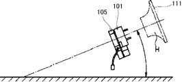
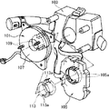
従来のこの種の回転コネクタ装置としては、例えば図10、図11に示すものがある。この従来の回転コネクタ装置101は、ステアリング・シャフトに装着された車体側のコンビネーション・スイッチ103に取り付けられている。回転コネクタ装置101とコンビネーション・スイッチ103との間には、自動車の各種制御のためにステアリング・ホイール111の操作角を検出する舵角センサ105が介設されている。
Examples of this type of conventional rotary connector device include those shown in FIGS. The conventional
回転コネクタ装置101の回転側部材であるディスク107には、一対の嵌合ボス109が突設され、ステアリング・ホイール111側に係合し、ディスク107がステアリング・ホイール111に連動回転可能となっている。
A pair of
回転コネクタ装置101と舵角センサ105とは、嵌合部113により結合されている。嵌合部113は、ディスク107とは別体であり、ディスク107に装着されて舵角センサ105まで延びている。嵌合部113の外周面には、係合溝113aが形成され、舵角センサ105の減速歯車の内周面に形成されたジョイント突部105aに係合する。
The
従って、ステアリング・ホイール111が回転すると嵌合ボス109、ディスク107、係合溝113a、及びジョイント突部105aを介して舵角センサ105に回転伝達され、操舵角を検出することができる。
Accordingly, when the
しかし、嵌合部113は、ディスク107に装着されると共に係合溝113及びジョイント突部105aの係合を介してディスク107から舵角センサ105へ回転を伝達する構造であるため、ステアリング・ホイール111とディスク107との間、嵌合部113と舵角センサ105との間に加え、ディスク107と嵌合部113との間の3カ所の係合を介して回転伝達することになるため、それぞれの部材間に発生するガタにより回転角伝達に大きな誤差を生じる恐れがある。
However, the
このような大きな誤差は、ステアリング・ホイール111の操舵に対して舵角センサ105の舵角検出誤差の増大となって現れ、タイムリーな車両制御に限界を生じるという問題があった。
Such a large error appears as an increase in the steering angle detection error of the
解決しようとする問題点は、ステアリング・ホイール111と舵角センサ105との間の回転伝達に大きな誤差を生じて舵角検出誤差の増大となって現れ、タイムリーな車両制御に限界を生じる点である。
The problem to be solved is that a large error is generated in the rotation transmission between the
本発明の回転コネクタ装置は、ステアリング・ホイールと舵角センサとの間の回転伝達の誤差を抑制して舵角検出誤差の増大を抑え、タイムリーな車両制御を行わせるため、静止側に支持されステアリング・シャフトを貫通させる固定側部材と、前記ステアリング・シャフトを貫通させる回転側部材と、前記固定側部材に対して前記回転側部材を回転自在に結合するとともに該回転側部材と連動回転するアタッチメントとを備え、前記アタッチメントに、舵角センサと係合して回転を伝達するセンサ係合部を設けた回転コネクタ装置であって、前記アタッチメントに、ステアリング・ホイールと係合するホイール係合部を設けたことを最も主要な特徴とする。 The rotary connector device of the present invention is supported on the stationary side in order to suppress an increase in the steering angle detection error by suppressing an error in rotation transmission between the steering wheel and the steering angle sensor and to perform timely vehicle control. A stationary member that penetrates the steering shaft, a rotating member that penetrates the steering shaft, and the rotating member that is rotatably coupled to the stationary member and that rotates in conjunction with the rotating member. A rotary connector device provided with a sensor engaging portion that engages with a rudder angle sensor and transmits rotation to the attachment, the wheel engaging portion engaging with a steering wheel on the attachment The most important feature is that
本発明は、かかる主要な特徴により、ステアリング・ホイールと舵角センサとの間は、ステアリング・ホイールとアタッチメントとの間、アタッチメントと舵角センサとの間の2カ所の係合により回転伝達をすることができ、舵角検出誤差の増大を抑え、タイムリーな車両制御を行わせることができる。 According to the main feature of the present invention, rotation is transmitted between the steering wheel and the steering angle sensor by engagement between the steering wheel and the attachment, and between the attachment and the steering angle sensor. Therefore, an increase in the steering angle detection error can be suppressed and timely vehicle control can be performed.
ステアリング・ホイールと舵角センサとの間の回転伝達の誤差を抑制して舵角検出誤差の増大を抑え、タイムリーな車両制御を行わせるという目的を、アタッチメントにステアリング・ホイールと係合するホイール係合部を設けることで実現した。 A wheel that engages the steering wheel to the attachment for the purpose of suppressing the increase in the steering angle detection error by suppressing the rotation transmission error between the steering wheel and the steering angle sensor, and performing timely vehicle control. This was realized by providing an engaging part.
図1は、本発明の一実施形態を適用した回転コネクタ装置の分解斜視図、図2は、回転コネクタ装置をステアリング・ホイール側から見た斜視図、図3(a)は、回転コネクタ装置を舵角センサ側から見た斜視図、(b)は、舵角センサを回転コネクタ装置側から見た平面図である。 FIG. 1 is an exploded perspective view of a rotary connector device to which an embodiment of the present invention is applied, FIG. 2 is a perspective view of the rotary connector device viewed from the steering wheel side, and FIG. The perspective view seen from the rudder angle sensor side, (b) is the top view which looked at the rudder angle sensor from the rotation connector apparatus side.
この図1〜図3に示す回転コネクタ装置1は、自動車のステアリング・ホイール側のホーン、エア・バッグ装置等を車体側へ電気的に接続するものである。回転コネクタ装置1は、固定側部材としてのボディ3と回転側部材としてのロータ5と遊動スペーサ7と図示しないフラット・ケーブルとを備えている。
The rotary connector device 1 shown in FIGS. 1 to 3 electrically connects a horn on the steering wheel side of an automobile, an air bag device, and the like to the vehicle body side. The rotary connector device 1 includes a
前記ボディ3は、ボトム・カバー9に、ケース11を係合させたものである。ボトム・カバー9は、ステアリング・コラム(図示せず)に固定したコンビネーション・スイッチ側に固定される。
The
前記ボトム・カバー9は、樹脂等によってドーナツ形状に形成され、中央部にステアリング・シャフトを貫通させる固定側孔部13が形成され、側部に固定側コネクタ部15を構成する固定側ターミナル支持部17が形成されている。固定側ターミナル支持部17に、固定側ターミナル21を保持した固定側ホルダ19が支持され、固定側コネクタ部15が構成される。
The bottom cover 9 is formed in a donut shape by resin or the like, a fixed
前記ロータ5は、ステアリング・ホイールの下面側に配置され、ステアリング・ホイールに対し連動回転可能となっている。ロータ5は、樹脂等によってドーナツ形状に形成され、中央部にステアリング・シャフトを貫通させる回転側孔部23が形成され、側部に回転側コネクタ部25を構成する回転側ターミナル支持部27が形成されている。回転側ターミナル支持部27に、回転側ターミナル31を保持した回転側ホルダ29が支持され、回転側コネクタ部25が構成される。
The
このロータ5は、ボディ3のボトム・カバー9にアタッチメント33を介し回転自在に結合されている。この結合のために、回転側孔部23の内周には、結合突起35が例えば周方向90°配置で4個所に形成されている。
The
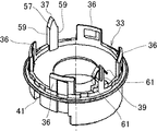
図4は、アタッチメントの斜視図である。 FIG. 4 is a perspective view of the attachment.
前記アタッチメント33は、樹脂によって筒状に形成され、図1〜図4のように、軸方向の一側に周方向90°配置で4箇所の弾性舌片36と該弾性舌片36間に対向配置された2箇所のステアリングホイール係合部としてホイール係合突起37,39とを備え、軸方向の他側に2個所の舵角センサ係合部としてセンサ係合凹部41,43が対向配置されている。センサ係合凹部43は、センサ係合凹部41よりも周方向の幅が若干大きく形成され、予備的な係合を行う。
The
アタッチメント33がボトム・カバー9側から固定側孔部13及び回転側孔部23間に装着され、弾性舌片36が回転側孔部23内の結合突起35を係止することでロータ5がボディ3に回転自在に結合される。
The
ホイール係合突起37,39は、回転側孔部23内周に沿ってステアリング・シャフトの軸方向へ突設された構成となり、このホイール係合突起37,39がステアリング・ホイール側のホイール係合凹部53,55に係合し、アタッチメント33及びロータ5を、ステアリング・ホイールに対し連動回転可能とする。ホイール係合突起37,39及びホイール係合凹部53,55の関係は、後述する。センサ係合凹部41,43は、静止側の舵角センサ45のセンサ係合突部47,49に係合する。
The
このとき、センサ係合凹部41は、センサ係合突部47に密に係合して該センサ係合突部47を回転させ、センサ係合凹部43は、センサ係合突部49に遊嵌して予備的な係合を行う。この係合により、静止側のコンビネーション・スイッチに支持された舵角センサ45にステアリング・ホイール側の回転を伝達する構成となる。
At this time, the
前記遊動スペーサ7は、ロータ5とボディ3との間に回転自在に配設されている。フラット・ケーブルは、遊動スペーサ7を介して巻回されている。フラット・ケーブルの両端は、固定側ターミナル21と回転側ターミナル31とに結合されている。
The
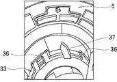
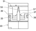
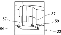
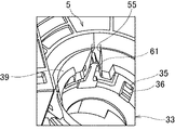
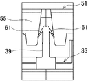
図5は、アタッチメントの一方のホイール係合突起を示す要部斜視図、図6は、アタッチメントの一方のホイール係合突起とステアリング・ホイールのホイール係合凹部との係合を示す要部正面図、図7は、アタッチメントの一方のホイール係合突起を示す要部拡大斜視図、図8は、アタッチメントの他方のホイール係合突起とステアリング・ホイールのホイール係合凹部との係合を示す要部斜視図、図9は、同要部正面図である。 FIG. 5 is a perspective view of the main part showing one wheel engagement protrusion of the attachment, and FIG. 6 is a front view of the main part showing engagement between the one wheel engagement protrusion of the attachment and the wheel engagement recess of the steering wheel. 7 is an enlarged perspective view of a main part showing one wheel engaging protrusion of the attachment, and FIG. 8 is a main part showing engagement between the other wheel engaging protrusion of the attachment and the wheel engaging recess of the steering wheel. A perspective view and FIG. 9 are front views of the main part.
図1〜図6のように、前記アタッチメント33の一方のホイール係合突起37は、ステアリング・ホイール51の一方のホイール係合凹部53に緩み無く密に係合し、ロータ5をステアリング・ホイール51に対し連動回転可能とする。図1〜図4,図8,図9のように、アタッチメント33の他方のホイール係合突起39は、ステアリング・ホイール51の他方のホイール係合凹部55に弾性的に係合し、予備的な係合を維持する。
As shown in FIGS. 1 to 6, one
図1〜図7のように、一方のホイール係合突起37は、先端部57が先細に形成され、両側に潰し用の突縁部59が形成されている。
As shown in FIGS. 1 to 7, one
図1〜図4,図8,図9のように、他方のホイール係合突起39には、先端部に弾接用の一対の弾性片部61が形成されている。
As shown in FIGS. 1 to 4, 8, and 9, the other
従って、コンビネーション・スイッチに舵角センサ45及び回転コネクタ装置1を取り付けると回転コネクタ装置1側のセンサ係合凹部41,43が、舵角センサ45のセンサ係合突部47,49に係合する。
Therefore, when the
また、ステリング・シャフトにステアリング・ホイール51を結合すると、アタッチメント33の一方のホイール係合突起37がステアリング・ホイール51側のホイール係合凹部53にステアリング・シャフトの軸方向から差し込まれるように係合し、この係合により突縁部59が回転側孔部23のほぼ周方向に沿って潰される。従って、ホイール係合突起37は、ステアリング・ホイール51の一方のホイール係合凹部53に緩み無く密に係合し、ロータ5を、ステアリング・ホイール51に対し連動回転可能とする。また、ステアリング・ホイール51の回転をアタッチメント33から舵角センサ45のセンサ係合突部47,49へ伝達する。
Further, when the
アタッチメント33の他方のホイール係合突起39は、ステアリング・ホイール51の他方のホイール係合凹部55に弾性片部61の変形により弾性的に係合し、予備的な係合を維持する。この予備的な係合により一方のホイール係合突起37が破損したときにも他方のホイール係合突起39により係合を維持することができる。
The other
従って、ステアリング・ホイール51が回転すると、ホイール係合凹部53、ホイール係合突起37、アタッチメント33を介してロータ5が連動回転する。また、ステアリング・ホイール51が回転すると、ホイール係合凹部53、ホイール係合突起37、アタッチメント33、センサ係合凹部41、舵角センサ45のセンサ係合突部47に回転が伝達される。舵角センサ45は、この回転に基づき所定の演算を行ってステアリング・ホイール51の操舵角を検出する。
[実施例の効果]
本発明の実施例では、コンビネーション・スイッチ側に支持されステアリング・シャフトを貫通させるボディ3と、前記ステアリング・シャフトを貫通させるロータ5と、前記ボディ3に対して前記ロータ5を回転自在に結合するとともに該ロータ5と連動回転するアタッチメント33とを備え、前記アタッチメント33に、舵角センサ45と係合して回転を伝達するセンサ係合凹部41,43を設けた回転コネクタ装置1であって、前記アタッチメント33に、ステアリング・ホイールと係合するホイール係合突起37,39を設けた。
Accordingly, when the
[Effect of Example]
In an embodiment of the present invention, a
このため、ステアリング・ホイール51と舵角センサ45との間は、ステアリング・ホイール51とアタッチメント33との間、アタッチメント33と舵角センサ45との間の2カ所の係合により回転角伝達をすることができ、舵角検出誤差の増大を抑え、タイムリーな車両制御を行わせることができる。
For this reason, between the
前記ボディ3とロータ5とは、前記ステアリング・シャフトを貫通させる固定側孔部13と同回転側孔部23とを各別に備え、前記アタッチメント33は、筒状であって前記固定側孔部13及び回転側孔部23に嵌合装着され、前記ホイール係合突起37,39を、前記回転側孔部23内周に沿って前記ステアリング・シャフトの軸方向へ突設した。
The
このため、ステアリング・ホイール51をステアリング・シャフトに取り付けるだけでホイール係合突起37,39をステアリング・ホイール51のホイール係合凹部53,55に係合させることができる。
Therefore, the
1 回転コネクタ装置
3 ボディ(固定側部材)
5 ロータ(回転側部材)
13 固定側孔部
23 回転側孔部
33 アタッチメント
37,39 ホイール係合突起(ホイール係合部)
41,43 センサ係合凹部(センサ係合部)
45 舵角センサ
51 ステアリング・ホイール
1 Rotating
5 Rotor (Rotation side member)
13
41, 43 Sensor engaging recess (sensor engaging portion)
45
Claims (2)
前記アタッチメントに、舵角センサと係合して回転を伝達するセンサ係合部を設けた回転コネクタ装置であって、
前記アタッチメントに、ステアリング・ホイールと係合するホイール係合部を設けた、
ことを特徴とする回転コネクタ装置。 A stationary member that is supported on the stationary side and penetrates the steering shaft, a rotational member that penetrates the steering shaft, and the rotational member that is rotatably coupled to the stationary member and the rotational member And an attachment that rotates in conjunction with
A rotation connector device provided with a sensor engagement portion that engages with a rudder angle sensor and transmits rotation to the attachment,
The attachment is provided with a wheel engaging portion that engages with a steering wheel.
A rotary connector device.
前記固定側部材と回転側部材とは、前記ステアリング・シャフトを貫通させる固定側孔部と同回転側孔部とを各別に備え、
前記アタッチメントは、筒状であって前記固定側孔部及び回転側孔部に嵌合装着され、
前記ホイール係合部を、前記回転側孔部内周に沿って前記ステアリング・シャフトの軸方向へ突設した、
ことを特徴とする回転コネクタ装置。 The rotary connector device according to claim 1,
The fixed side member and the rotation side member are each provided with a fixed side hole portion and a rotation side hole portion that penetrate the steering shaft,
The attachment is cylindrical and is fitted and attached to the fixed side hole and the rotation side hole,
The wheel engaging portion is provided in the axial direction of the steering shaft along the inner periphery of the rotation side hole,
A rotary connector device.
Priority Applications (3)
| Application Number | Priority Date | Filing Date | Title |
|---|---|---|---|
| JP2008160647A JP5259265B2 (en) | 2008-06-19 | 2008-06-19 | Rotating connector device |
| US12/457,618 US7798816B2 (en) | 2008-06-19 | 2009-06-17 | Rotary connector device |
| DE102009025371A DE102009025371A1 (en) | 2008-06-19 | 2009-06-18 | Rotary connector device |
Applications Claiming Priority (1)
| Application Number | Priority Date | Filing Date | Title |
|---|---|---|---|
| JP2008160647A JP5259265B2 (en) | 2008-06-19 | 2008-06-19 | Rotating connector device |
Publications (2)
| Publication Number | Publication Date |
|---|---|
| JP2010000868A JP2010000868A (en) | 2010-01-07 |
| JP5259265B2 true JP5259265B2 (en) | 2013-08-07 |
Family
ID=41335186
Family Applications (1)
| Application Number | Title | Priority Date | Filing Date |
|---|---|---|---|
| JP2008160647A Expired - Fee Related JP5259265B2 (en) | 2008-06-19 | 2008-06-19 | Rotating connector device |
Country Status (3)
| Country | Link |
|---|---|
| US (1) | US7798816B2 (en) |
| JP (1) | JP5259265B2 (en) |
| DE (1) | DE102009025371A1 (en) |
Families Citing this family (16)
| Publication number | Priority date | Publication date | Assignee | Title |
|---|---|---|---|---|
| JP5123070B2 (en) * | 2008-06-19 | 2013-01-16 | ナイルス株式会社 | Rotating connector device |
| JP5241016B2 (en) * | 2009-01-29 | 2013-07-17 | 矢崎総業株式会社 | Rotating connector |
| WO2011107144A1 (en) * | 2010-03-02 | 2011-09-09 | Abb Research Ltd | A system for electrically connecting a tool to a robot wrist and a method therefor |
| JP5203408B2 (en) * | 2010-03-26 | 2013-06-05 | 古河電気工業株式会社 | Rotating connector device |
| JP5041447B2 (en) * | 2010-03-30 | 2012-10-03 | 古河電気工業株式会社 | Rotating connector device |
| JP5331052B2 (en) * | 2010-04-22 | 2013-10-30 | 古河電気工業株式会社 | Rotating connector mating structure |
| KR101789820B1 (en) * | 2011-04-15 | 2017-10-25 | 엘지이노텍 주식회사 | Angle sensor |
| JP2016013763A (en) * | 2014-07-02 | 2016-01-28 | パイオニア株式会社 | Non-contact power transmission device |
| EP2987682B1 (en) * | 2014-08-20 | 2020-12-16 | Nexans | Assembly for electrical wires installed in a motor vehicle |
| JP6498893B2 (en) * | 2014-09-12 | 2019-04-10 | 古河電気工業株式会社 | Rotating connector device |
| KR102274643B1 (en) * | 2016-09-12 | 2021-07-07 | 후루카와 덴키 고교 가부시키가이샤 | rotary connector device |
| JP2019066232A (en) * | 2017-09-29 | 2019-04-25 | ダイハツ工業株式会社 | Steering angle sensor attachment structure |
| CN112055920B (en) * | 2018-05-28 | 2022-09-09 | 古河电气工业株式会社 | Rotary connector device and rotary body of rotary connector device |
| JP7054646B2 (en) | 2018-05-29 | 2022-04-14 | 株式会社東海理化電機製作所 | Rotating structure |
| WO2020121741A1 (en) * | 2018-12-13 | 2020-06-18 | 古河電気工業株式会社 | Rotary connector device |
| CN114735070A (en) * | 2022-05-09 | 2022-07-12 | 浙江吉利控股集团有限公司 | Steering wheel containing novel wire harness conversion device |
Family Cites Families (13)
| Publication number | Priority date | Publication date | Assignee | Title |
|---|---|---|---|---|
| JPH0711424Y2 (en) * | 1990-10-05 | 1995-03-15 | 古河電気工業株式会社 | Rotating connector |
| JPH0858602A (en) * | 1994-08-26 | 1996-03-05 | Yazaki Corp | Electrical connection device between steering wheel and steering column |
| US5630723A (en) * | 1994-11-30 | 1997-05-20 | Nihon Plast Co., Ltd. | Cable type electric connector |
| JPH08193842A (en) * | 1995-01-11 | 1996-07-30 | Niles Parts Co Ltd | Rotation detection device installed on cable reel |
| JP3637120B2 (en) * | 1995-11-01 | 2005-04-13 | ナイルス株式会社 | Combination switch device with rotating connector |
| JP4105291B2 (en) | 1998-06-16 | 2008-06-25 | 富士重工業株式会社 | Steering mechanism and assembly method thereof |
| JP2000304522A (en) * | 1999-04-23 | 2000-11-02 | Tokai Rika Co Ltd | Steering roll connector |
| JP2000318516A (en) * | 1999-05-11 | 2000-11-21 | Harness Syst Tech Res Ltd | Rotary connection device for steering and structure of steering unit |
| JP2001167858A (en) * | 1999-12-13 | 2001-06-22 | Niles Parts Co Ltd | Rotation connector device |
| JP4024025B2 (en) * | 2001-10-11 | 2007-12-19 | ナイルス株式会社 | Rotating connector device |
| JP2005011544A (en) * | 2003-06-16 | 2005-01-13 | Alps Electric Co Ltd | Rotary connector |
| JP4602176B2 (en) * | 2005-07-01 | 2010-12-22 | 矢崎総業株式会社 | Rotating connector device |
| JP4152414B2 (en) * | 2006-02-09 | 2008-09-17 | 矢崎総業株式会社 | Rotating connector device |
-
2008
- 2008-06-19 JP JP2008160647A patent/JP5259265B2/en not_active Expired - Fee Related
-
2009
- 2009-06-17 US US12/457,618 patent/US7798816B2/en not_active Expired - Fee Related
- 2009-06-18 DE DE102009025371A patent/DE102009025371A1/en not_active Withdrawn
Also Published As
| Publication number | Publication date |
|---|---|
| US20090317994A1 (en) | 2009-12-24 |
| DE102009025371A1 (en) | 2009-12-24 |
| JP2010000868A (en) | 2010-01-07 |
| US7798816B2 (en) | 2010-09-21 |
Similar Documents
| Publication | Publication Date | Title |
|---|---|---|
| JP5259265B2 (en) | Rotating connector device | |
| KR101398046B1 (en) | Shaft coupling mechanism | |
| JP5825519B2 (en) | Steering device | |
| JP5123070B2 (en) | Rotating connector device | |
| CN102822011B (en) | Rotary connector unit | |
| CN103262364B (en) | Rotary connector device | |
| JP2011207402A5 (en) | ||
| WO2015190054A1 (en) | Shaft coupling mechanism for electric power steering device | |
| JPS59230861A (en) | Tilting steering gear | |
| KR20120104791A (en) | Outer roller for tripod constant velocity joint | |
| JP4105291B2 (en) | Steering mechanism and assembly method thereof | |
| JP5682775B2 (en) | Vehicle steering system | |
| JP2015217704A (en) | Electric power steering device | |
| WO2018192454A1 (en) | Automobile power steering sensor | |
| JP5411524B2 (en) | Rotation angle sensor and vehicle equipped with the same | |
| JP5607463B2 (en) | Electric power steering device | |
| JP7594158B1 (en) | Electric power steering device | |
| JP5203408B2 (en) | Rotating connector device | |
| JP5195267B2 (en) | Vehicle steering device | |
| JP2020118255A (en) | Joint device and motor | |
| JP2020111108A (en) | Steering device | |
| KR20120137035A (en) | Electric power steering device | |
| JP5335341B2 (en) | motor | |
| JP2010120465A (en) | Steering angle detection device | |
| JPWO2020009140A1 (en) | Rolling bearing unit |
Legal Events
| Date | Code | Title | Description |
|---|---|---|---|
| A621 | Written request for application examination |
Free format text: JAPANESE INTERMEDIATE CODE: A621 Effective date: 20110601 |
|
| A977 | Report on retrieval |
Free format text: JAPANESE INTERMEDIATE CODE: A971007 Effective date: 20121102 |
|
| A131 | Notification of reasons for refusal |
Free format text: JAPANESE INTERMEDIATE CODE: A131 Effective date: 20121113 |
|
| TRDD | Decision of grant or rejection written | ||
| A01 | Written decision to grant a patent or to grant a registration (utility model) |
Free format text: JAPANESE INTERMEDIATE CODE: A01 Effective date: 20130416 |
|
| A61 | First payment of annual fees (during grant procedure) |
Free format text: JAPANESE INTERMEDIATE CODE: A61 Effective date: 20130424 |
|
| FPAY | Renewal fee payment (event date is renewal date of database) |
Free format text: PAYMENT UNTIL: 20160502 Year of fee payment: 3 |
|
| R150 | Certificate of patent or registration of utility model |
Ref document number: 5259265 Country of ref document: JP Free format text: JAPANESE INTERMEDIATE CODE: R150 Free format text: JAPANESE INTERMEDIATE CODE: R150 |
|
| S111 | Request for change of ownership or part of ownership |
Free format text: JAPANESE INTERMEDIATE CODE: R313111 |
|
| R350 | Written notification of registration of transfer |
Free format text: JAPANESE INTERMEDIATE CODE: R350 |
|
| R250 | Receipt of annual fees |
Free format text: JAPANESE INTERMEDIATE CODE: R250 |
|
| R250 | Receipt of annual fees |
Free format text: JAPANESE INTERMEDIATE CODE: R250 |
|
| R250 | Receipt of annual fees |
Free format text: JAPANESE INTERMEDIATE CODE: R250 |
|
| R250 | Receipt of annual fees |
Free format text: JAPANESE INTERMEDIATE CODE: R250 |
|
| LAPS | Cancellation because of no payment of annual fees |


