JP5259258B2 - Endoscope device - Google Patents
Endoscope device Download PDFInfo
- Publication number
- JP5259258B2 JP5259258B2 JP2008143031A JP2008143031A JP5259258B2 JP 5259258 B2 JP5259258 B2 JP 5259258B2 JP 2008143031 A JP2008143031 A JP 2008143031A JP 2008143031 A JP2008143031 A JP 2008143031A JP 5259258 B2 JP5259258 B2 JP 5259258B2
- Authority
- JP
- Japan
- Prior art keywords
- tightening
- end side
- treatment instrument
- proximal end
- distal end
- Prior art date
- Legal status (The legal status is an assumption and is not a legal conclusion. Google has not performed a legal analysis and makes no representation as to the accuracy of the status listed.)
- Active
Links
- 238000011282 treatment Methods 0.000 claims description 91
- 238000003780 insertion Methods 0.000 claims description 56
- 230000037431 insertion Effects 0.000 claims description 56
- 230000002093 peripheral effect Effects 0.000 claims description 15
- 230000002265 prevention Effects 0.000 claims description 13
- 238000005452 bending Methods 0.000 description 19
- 238000003384 imaging method Methods 0.000 description 14
- 230000003287 optical effect Effects 0.000 description 7
- 238000012545 processing Methods 0.000 description 5
- 238000005286 illumination Methods 0.000 description 3
- 239000000758 substrate Substances 0.000 description 3
- 238000012986 modification Methods 0.000 description 2
- 230000004048 modification Effects 0.000 description 2
- 206010052428 Wound Diseases 0.000 description 1
- 208000027418 Wounds and injury Diseases 0.000 description 1
- XAGFODPZIPBFFR-UHFFFAOYSA-N aluminium Chemical compound [Al] XAGFODPZIPBFFR-UHFFFAOYSA-N 0.000 description 1
- 229910052782 aluminium Inorganic materials 0.000 description 1
- 239000000470 constituent Substances 0.000 description 1
- 238000005260 corrosion Methods 0.000 description 1
- 230000007797 corrosion Effects 0.000 description 1
- 238000000034 method Methods 0.000 description 1
- 210000000056 organ Anatomy 0.000 description 1
- 230000003014 reinforcing effect Effects 0.000 description 1
- 239000011347 resin Substances 0.000 description 1
- 229920005989 resin Polymers 0.000 description 1
- 238000012360 testing method Methods 0.000 description 1
Images

Landscapes
- Instruments For Viewing The Inside Of Hollow Bodies (AREA)
- Endoscopes (AREA)
Description
本発明は、処置具挿通路を具備する内視鏡装置に関する。 The present invention relates to an endoscope apparatus including a treatment instrument insertion passage.
内視鏡装置は、医療分野及び工業用分野において広く利用されている。医療分野において用いられる内視鏡装置は、内視鏡の細長い挿入部を体腔内に挿入することによって、体腔内の臓器を観察したり、必要に応じて処置具の挿通チャンネル内に挿入した処置具を用いて各種処置をしたりすることができる。 Endoscopic devices are widely used in the medical field and industrial field. An endoscope apparatus used in the medical field observes an organ in a body cavity by inserting an elongated insertion portion of the endoscope into a body cavity, or inserts into an insertion channel of a treatment instrument as necessary. Various kinds of treatments can be performed using tools.
また、工業用分野において用いられる内視鏡装置は、内視鏡の細長い挿入部をジェットエンジン内や、工場の配管等に挿入することによって、被検部位の傷及び腐蝕等の観察や各種処置等を行うことができる。 Endoscopic devices used in the industrial field are also used to observe wounds, corrosion, and other treatments on the test site by inserting the long and thin insertion portion of the endoscope into a jet engine or factory piping. Etc. can be performed.
このような工業用の内視鏡装置には、例えば先端部に、撮像レンズやCCD等の撮像素子を有する撮像ユニットが配設された細長の挿入部を有する内視鏡と、この内視鏡が接続された装置本体とにより構成されているものがある。尚、小型の内視鏡装置においては、挿入部の先端にLED等の光源が配設されているものもある。 In such an industrial endoscope apparatus, for example, an endoscope having an elongated insertion portion in which an imaging unit having an imaging element such as an imaging lens or a CCD is disposed at a distal end portion, and the endoscope There are some which are configured by an apparatus main body to which is connected. In some small-sized endoscope apparatuses, a light source such as an LED is disposed at the distal end of the insertion portion.
装置本体内には、内視鏡を駆動する各種部材、具体的には、撮像ユニットや光源の駆動を行う電気回路、撮像ユニットから出力された撮像後の画像信号を処理する画像処理ユニット、この画像処理ユニットにより処理された画像データを記録する記録媒体、表示部及び内視鏡や装置本体に電力を供給するバッテリ等が設けられている。 In the apparatus main body, various members for driving the endoscope, specifically, an electric circuit for driving the imaging unit and the light source, an image processing unit for processing an image signal after imaging output from the imaging unit, A recording medium for recording image data processed by the image processing unit, a display unit, an endoscope, a battery for supplying power to the apparatus main body, and the like are provided.
また、内視鏡は、挿入部に、先端部を上下方向及び左右方向の任意の方向に湾曲させるための湾曲部と、鉗子等の処置具を挿入するための処置具チャンネルとを設けて構成されたものも周知である。また、内視鏡は、湾曲部の湾曲動作等の操作を行うための例えばジョィスティック等で構成された操作部を有している。 In addition, the endoscope is configured by providing the insertion portion with a bending portion for bending the distal end portion in any direction of the vertical direction and the left-right direction, and a treatment instrument channel for inserting a treatment instrument such as forceps. What is done is also well known. In addition, the endoscope has an operation unit configured by, for example, a joystick for performing an operation such as a bending operation of the bending unit.
このような内視鏡を有する従来の内視鏡装置としては、操作部による湾曲部の湾曲操作と、処置具等の操作の両方を簡単に行うことができ、操作性を向上させるための構成を有する内視鏡装置が、例えば特許文献1によって開示されている。 As a conventional endoscope apparatus having such an endoscope, it is possible to easily perform both the bending operation of the bending portion by the operation portion and the operation of the treatment instrument and the like, and the configuration for improving the operability For example, Patent Document 1 discloses an endoscope apparatus having the following.
特許文献1に開示された内視鏡装置は、操作部と、挿入部の先端側に開口する先端側開口端と挿入部の基端側に開口する基端側開口端との間を連通する処置具チャンネルとを備え、この処置具チャンネルの基端側開口端の周辺部と操作部との間を着脱可能に連結する連結部を設け、操作部と基端側開口端の周辺部との間を連結した状態で、操作部の湾曲操作の作動領域と干渉しない位置に処置具チャンネルの基端側開口端を配置した構成となっている。 The endoscope apparatus disclosed in Patent Document 1 communicates between an operation unit and a distal end side opening end that opens to the distal end side of the insertion portion and a proximal end side opening end that opens to the proximal end side of the insertion portion. A treatment instrument channel, and a connecting portion that removably couples the peripheral portion of the proximal end side opening end of the treatment instrument channel and the operation portion. In this state, the proximal end side opening end of the treatment instrument channel is arranged at a position where it does not interfere with the operation region of the bending operation of the operation unit.
また、特許文献1の内視鏡装置には、処置具チャンネルに挿通され基端側開口端を介して導出されるフック処置具のワイヤを締付けて固定する固定金具等のロック機構を連結部に設けた構成が開示されている。 In addition, in the endoscope apparatus of Patent Document 1, a locking mechanism such as a fixing fitting that fastens and fixes a wire of a hook treatment instrument that is inserted into a treatment instrument channel and led out through a proximal end side opening end is used as a connection portion. The provided arrangement is disclosed.
このロック機構を構成する固定金具は、連結部の基端側開口端に設けられて挿通するフック処置具のワイヤをねじの螺合により押圧して締め付け可能な押圧部を備えた締め付け固定部と、この締め付け固定部に螺合することで、締め付け固定部の押圧部の締め付けにより基端側開口端に挿通する処置具のワイヤを締め付け固定する締め付けナットとを有して構成されている。 The fixing bracket that constitutes the lock mechanism includes a fastening portion provided with a pressing portion that can be fastened by pressing a wire of a hook treatment instrument that is provided at the proximal end side opening end of the connecting portion and is inserted by screwing. And, it is configured to have a tightening nut for tightening and fixing the wire of the treatment instrument inserted into the proximal end side opening end by tightening of the pressing portion of the tightening fixing portion by screwing into the tightening fixing portion.
このようなロック機構を備えた構成により、特許文献1の内視鏡装置は、連結部の基端側開口端により導出されるフック処置具のワイヤを、ロック機構の締め付け固定部と締め付けナットとの螺合による締め付け固定によって、フック処置具のフック部を例えばタービンブレードに引っ掛けた状態で係止することを可能にしている。
しかしながら、特許文献1に記載の内視鏡装置では、ロック機構を構成する締め付け固定部と締め付けナットとが夫々分離する別部材であるため、締め付けナットを締め付け固定部から取り外した後、締め付けナットを紛失してしまう可能性があった。また、締め付けナットはフック処置具のワイヤの固定用であるため、フック処置具ではない処置具を内視鏡に用いる場合にも、同様の問題が生じてしまう。 However, in the endoscope apparatus described in Patent Document 1, since the tightening fixing portion and the tightening nut constituting the lock mechanism are separate members, the tightening nut is removed after the tightening nut is removed from the tightening fixing portion. There was a possibility of losing. In addition, since the tightening nut is used for fixing the wire of the hook treatment tool, the same problem occurs when a treatment tool that is not a hook treatment tool is used for an endoscope.
また、フック処置具を内視鏡に装着する際には、分離した締め付けナットを手に持ちながらこの締め付けナット及び締め付け固定部にフック処置具のワイヤを挿通した後に、この締め付けナットを螺合して締め付け固定しなければならず、操作性が悪いといった問題点もあった。 When attaching the hook treatment instrument to the endoscope, hold the separated tightening nut in your hand and insert the hook treatment instrument wire through the tightening nut and tightening fixing part, and then screw the tightening nut. There is also a problem that the operability is poor because it has to be tightened and fixed.
そこで、本発明は前記問題点に鑑みてなされたもので、ロック機構の操作性を向上させた内視鏡装置を提供することを目的とする。 Therefore, the present invention has been made in view of the above problems, and an object thereof is to provide an endoscope apparatus in which the operability of the lock mechanism is improved.
本発明の内視鏡装置は、先端部に開口する先端側開口端と、基端側に開口する基端側開口端との間を連通する処置具挿通路を備えた挿入部と、前記基端側開口端に配置された処置具挿通口金部を有し、前記処置挿通路に挿通する処置具のワイヤを前記基端側開口端にて締め付け固定するロック機構を備えた連結部と、を具備する内視鏡装置であって、前記連結部の前記ロック機構は、前記処置具挿通路に挿通する処置具のワイヤを前記基端側開口端にて締め付けて固定可能な締め付け部を有する締め付け固定部と、前記締め付け固定部に相対的に回動自在に取り付けられ、この回動に連動して前記締め付け部を押圧して前記締め付け部を締め付ける押圧部を有する締め付け回動部と、前記締め付け回動部の前記締め付け固定部からの抜け落ちを防止する抜け落ち防止部と、を具備し、前記締め付け回動部は、内周面から突起する少なくとも1つの突起部を有し、前記抜け落ち防止部は、基端側が前記締め付け固定部の外周面と前記締め付け回動部材の内周面との間に配置され、先端側が前記締め付け固定部に固定された円筒状部材で構成されたもので、この円筒状部材の先端側に前記突起部を規制して前記締め付け回動部の抜け落ちを防止する規制部を設けて構成した。 An endoscope apparatus according to the present invention includes an insertion portion including a treatment instrument insertion passage that communicates between a distal end side opening end that opens to a distal end portion and a proximal end side opening end that opens to a proximal end side; A connecting portion having a lock mechanism that has a treatment instrument insertion base disposed at the end opening end, and clamps and fixes the wire of the treatment instrument inserted into the treatment insertion path at the proximal end opening end; An endoscopic apparatus comprising: a fastening portion having a fastening portion capable of fastening and fixing a wire of a treatment instrument inserted into the treatment instrument insertion path at the proximal end side opening end, wherein the locking mechanism of the connecting portion A fastening part, a fastening turning part that is rotatably attached to the fastening part, and has a pressing part that presses the fastening part in conjunction with the turning to fasten the fastening part; and the fastening part Falling off of the rotating part from the fastening part Anda preventing portion coming off preventing said clamping pivot unit has at least one protrusion protruding from the inner peripheral surface, the falling off preventing portion includes a base end side outer peripheral surface of the fastening part It is arranged between the inner peripheral surface of the tightening rotation member and is composed of a cylindrical member whose front end side is fixed to the tightening fixing portion. The protrusion is restricted to the front end side of the cylindrical member. And a restricting portion for preventing the tightening rotation portion from falling off.
本発明によれば、ロック機構の操作性を向上させた内視鏡装置を提供することが可能となる。 ADVANTAGE OF THE INVENTION According to this invention, it becomes possible to provide the endoscope apparatus which improved the operativity of the locking mechanism.
以下、図面を参照して本発明の実施の形態を説明する。
尚、以下、内視鏡装置は、ショルダ式の工業用の内視鏡装置を例に挙げて説明する。
Embodiments of the present invention will be described below with reference to the drawings.
Hereinafter, the endoscope apparatus will be described by taking a shoulder type industrial endoscope apparatus as an example.
(一実施の形態)
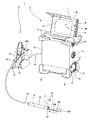
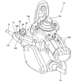
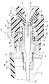
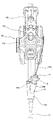
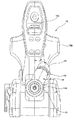
図1から図6は本発明の撮像装置の一実施の形態に係り、図1は一実施の形態の内視鏡装置を、装置本体からモニタを開成した状態で示す斜視図、図2は図1の連結部を備えた操作部を手元側からみた状態の斜視図、図3は図2の連結部の摘み部近傍の拡大斜視図、図4は連結部に設けられたロック機構の構成を説明するもので、図3の連結部の一部破断した断面図、図5は図2の操作部を上から見た場合の外観構成を示す上面図、図6は図5の操作部を連結部側から見た場合の正面図である。
(One embodiment)
1 to 6 relate to an embodiment of an imaging apparatus according to the present invention. FIG. 1 is a perspective view showing an endoscope apparatus according to an embodiment in a state where a monitor is opened from the apparatus main body. FIG. FIG. 3 is an enlarged perspective view of the vicinity of the knob portion of the connecting portion in FIG. 2, and FIG. 4 is a configuration of a lock mechanism provided in the connecting portion. FIG. 5 is a partially broken cross-sectional view of the connecting portion of FIG. 3, FIG. 5 is a top view showing an external configuration when the operating portion of FIG. 2 is viewed from above, and FIG. 6 is a connecting portion of the operating portion of FIG. It is a front view at the time of seeing from the part side.
図1に示すように、内視鏡装置1は、内視鏡2と、この内視鏡2に接続された装置本体3とにより主要部が構成されている。
内視鏡2は、細長で可撓性を有する挿入部13と、この挿入部13の挿入方向基端側に連結部14を介して接続された操作部15と、この操作部15から延出された可撓性を有する接続ケーブルであるユニバーサルコード16とにより主要部が構成されている。尚、図示はしないがユニバーサルコード16の延出端にはコネクタボックスが接続されており、ユニバーサルコード16及びコネクタボックスにより、内視鏡2と装置本体3とは接続されている。
As shown in FIG. 1, the endoscope apparatus 1 includes an endoscope 2 and a main body 3 connected to the endoscope 2.
The endoscope 2 includes an elongated and
ここで、まず、装置本体3の構成を説明し、本発明の主要部を有する内視鏡2の構成については後述する。
装置本体3は、例えば箱状を有しており、装置本体3の外装筐体4に、内視鏡2の撮像ユニットにより撮像された内視鏡画像を表示する画像表示面5を有するモニタ6が固定されている。
Here, first, the configuration of the apparatus body 3 will be described, and the configuration of the endoscope 2 having the main part of the present invention will be described later.
The apparatus main body 3 has, for example, a box shape, and a monitor 6 having an image display surface 5 that displays an endoscopic image captured by the imaging unit of the endoscope 2 on the exterior housing 4 of the apparatus main body 3. Is fixed.
詳しくは、モニタ6は、画像表示面5を有するモニタ面6aの裏面6bが、装置本体3の外装筐体4の図1中背面側に装着された図示しないコネクタボックスに対して開閉自在となるよう、蝶番等を介して装置本体3の外表面に固定されている。
Specifically, the monitor 6 can be opened and closed with respect to a connector box (not shown) attached to the back side of the exterior housing 4 of the apparatus body 3 in FIG. 1 on the
モニタ6は、内視鏡装置1が未使用の際は、モニタ6の裏面6bが、コネクタボックスを覆う閉位置に閉成され、内視鏡装置1が使用される際は、裏面6bが、コネクタボックスに対して離間してコネクタボックスを露出させる開位置に開成される。
When the endoscope device 1 is not used, the monitor 6 is closed at the closed position where the
モニタ6のモニタ面6aに、内視鏡装置1が未使用の際、画像表示面5を覆って保護するカバー板7が固定されている。カバー板7は、画像表示面5に対向するカバー板7の対向面7aが、画像表示面5に対して開閉自在となるよう、モニタ面6aに固定されている。
A
また、カバー板7は、内視鏡装置1が未使用の際は、カバー板7の対向面7aが、画像表示面5に対して当接して画像表示面5を覆う閉位置に閉成され、内視鏡装置1が使用される際は、対向面7aが、画像表示面5に対して離間する開位置に開成される。
When the endoscope apparatus 1 is not used, the
箱状の装置本体3の外装筐体4の角部に、装置本体3を戴置するための例えばNBR等のゴムにより形成された、複数の脚部8が固定されている。脚部8は、装置本体3を、地表等に対し、複数の姿勢により載置できるように設けられたものである。 A plurality of legs 8 made of rubber such as NBR for mounting the apparatus main body 3 is fixed to the corner of the outer casing 4 of the box-shaped apparatus main body 3. The leg part 8 is provided so that the apparatus main body 3 can be mounted with respect to the ground surface etc. with several attitude | positions.
装置本体3の外装筐体4の図1中背面側の図示しないコネクタボックス収容室に、前記コネクタボックスが、着脱コネクタ12により装着されている。このコネクタボックスの内部には、後述する内視鏡2の観察光学系を構成する撮像ユニットや光源の駆動を行う基板や、撮像ユニットから出力された被写体の画像信号を処理する画像処理用の基板等の電気部品が設けられている。
The connector box is mounted by a
また、装置本体3の外装筐体4により覆われた内部には、コネクタボックス以外の電気部品や、画像処理用の基板により画像処理された画像データを記録する記録媒体や、内視鏡2及び装置本体3に電力を供給する図示しないバッテリ等が設けられている。 Further, inside the apparatus main body 3 covered by the outer casing 4, an electrical component other than the connector box, a recording medium for recording image data processed by the image processing substrate, the endoscope 2, A battery or the like (not shown) that supplies power to the apparatus body 3 is provided.
このバッテリは、例えば外装筐体4の側面に対し、蝶番9により開閉自在に設けられたバッテリ用蓋体10の開閉により、装置本体3内に設けられた図示しないバッテリ収容室に対し、挿抜自在に収容される構成となっている。また、バッテリがバッテリ収容室に挿入され収容された後、バッテリ用蓋体10は、固定ピン11によりロックされる。尚、その他の装置本体3内の内容物の配置構造は、周知の構成であるため、その説明は省略する。
For example, the battery can be inserted into and removed from a battery housing chamber (not shown) provided in the apparatus main body 3 by opening and closing a
次に、本発明の主要部を有する内視鏡2の具体的な構成を図1〜6を参照して説明する。 Next, a specific configuration of the endoscope 2 having the main part of the present invention will be described with reference to FIGS.
図1に示すように、内視鏡2の挿入部13は、最先端位置に配置され、対物レンズ等の対物光学系及び被検部位を撮像するCCD等の撮像素子を有する撮像ユニット等で構成された観察用の観察光学系や被検部位を照明するための照明光学系等が組み込まれた先端部17と、この先端部17に連設され、遠隔的に湾曲操作可能な湾曲部18と、この湾曲部18の挿入方向基端側に連設される細長い可撓管部19とを有して構成されている。
As shown in FIG. 1, the
先端部17の先端面には、図1に示すように照明光学系用の照明窓20と、観察光学系用の観察窓21と、挿入部13の内部に配設された処置具挿通路である処置具チャンネル22a(図4参照)の先端側開口端22等が配設されている。
As shown in FIG. 1, an
さらに、挿入部13の先端側内部には、LED等の光源と、観察光学系の撮像ユニットのCCD等の撮像素子に接続された電気ケーブルと、湾曲部18を湾曲操作する湾曲操作ワイヤ等が配設されている。
Further, inside the distal end side of the
尚、挿入部13内に配設された処置具チャンネル22aは、先端側開口端と挿入部13の基端側の後述する基端側開口端33(図3及び図4参照)との間を連通している。
Incidentally, the
また、挿入部13の可撓管部19の基端部には、連結部14の先端部が連結されている。そして、この連結部14の基端側は、操作部15に接続されている。
Further, the distal end portion of the connecting
ここで、連結部14と操作部15との構成について図2を用いて説明する。
図2は操作部15をユニバーサルコード16側からみた後方の斜視図である。図2に示すように、操作部15は、本体部15Aと、この本体部15と一体的に設けられた把持部15Bと、挿入部13の湾曲部18の湾曲操作するための湾曲操作部を構成する例えばジョイスティック15Cとを有して構成されている。
尚、湾曲操作部は、ジョイスティック15Cに限定されるものではなく、他の入力手段を用いて構成しても良い。
Here, the structure of the
FIG. 2 is a rear perspective view of the
The bending operation unit is not limited to the
操作部15の後方側(ユニバーサルコード側)の本体部15Aからはユニバーサルコード16が延出されている。また、操作部15の前方側(挿入部側)の本体部15Aには連結部14が接続されている。
A
連結部14は、図1及び図2に示すように、挿入部13の基端側と操作部15との間に接続されている。そして、連結部14は、処置具チャンネル22a(図4)を内部に有し、処置具チャンネル22aに挿通するフック処置具23のワイヤ23bを基端側開口端33近傍にて締め付け固定するロック機構30を備えて構成されている。
As shown in FIGS. 1 and 2, the connecting
具体的には、連結部14は、本体14Aと、この本体14Aに一体的に構成され、処置具チャンネル22aが配置された処置具挿通口部14Bと、本体14Aと処置具挿通口部14Bとの補強枠部材である接続プレート14Cと、ロック機構30とを有して主要部が構成されている。
Specifically, the connecting
処置具挿通口部14Bには、図2及び図3に示すように、後述する締め付け回動部である摘み操作部31が配設されている。この摘み操作部31の内側には、例えばフック処置具23のワイヤ23bを基端側開口端33に案内すると共に、他の処置具を装着するための接続部32が装着されている。
As shown in FIGS. 2 and 3, the treatment
次に、本実施の形態の主要部である連結部14のロック機構30の構成を、図4を用いて説明する。
本実施の形態の内視鏡装置1において、連結部14のロック機構30は、図4に示すように、処置具チャンネル22aに挿通するフック処置具23のワイヤ23bを基端側開口端33近傍にて締め付けて固定可能な締め付け部36aを有する締め付け固定部36と、この締め付け固定部36に相対的に回動自在に取り付けられ、この回動に連動して締め付け部36aを押圧してこの締め付け部36aを締め付ける押圧部32aを有する締め付け回動部である摘み操作部31と、この摘み操作部31の締め付け固定部36からの抜け落ちを防止する抜け落ち防止部である抜け落ち防止部材37とを有して主要部が構成されている。尚、締め付け固定部である摘み操作部31は、締め付けナットに相当するものである。
Next, the configuration of the
In the endoscope apparatus 1 according to the present embodiment, as shown in FIG. 4, the
締め付け固定部36の基端側には、接続プレート14CにOリング35を介して装着された管状の処置具口金部材34が取り付けられている。この処置具口金部材34の挿入部13側には、固定部材39を介して処置具チャンネルチューブ40が固定されている。
A tubular treatment
そして、この固定部材39及び処置具チャンネルチューブ40を覆うようにチャンネルカバー14bが設けられている。このようにして処置具挿通口部14Bが形成されている。
A
締め付け固定部36の締め付け部36aは、先端側に基端側開口端33を有して先端部が先細のテーパー形状に形成されている。また、締め付け部36aは、基端側開口端33を介して処置具チャンネル22aの長手方向に切り欠き36cを有して構成されている。
The tightening
尚、締め付け部36aは、処置具チャンネル22a内に挿通されたワイヤ23bと接触して締め付ける接触部36a1を有して構成されている。
The tightening
そして、この締め付け部36aには、摘み操作部31に装着された接続部32の嵌合穴が嵌合される。この接続部32の嵌合穴は、内径が先細のテーパー形状に形成されており、この嵌合穴の内面が押圧部32aとして構成されている。
And the fitting hole of the
従って、接続部32が装着された摘み操作部31を回動させて接続部32を摘み操作部31の回動軸の挿入部13側方向に移動すると、接続部32の押圧部32aによって締め付け部36aを縮径する方向に押圧することで、処置具チャンネル22aに挿通するフック処置具23のワイヤ23bを基端側開口端33にて締め付けて固定できるようになっている。
Therefore, when the
このような締め付け固定部36の挿入部13側基端部には、ねじ部36bが形成されている。このねじ部36bには、摘み操作部31に設けられたねじ部31bが螺合される。すなわち、締め付け固定部36には、ねじ部36bとねじ部31bとの螺合によって摘み操作部31が相対的に回動自在に取り付けられている。
A
摘み操作部31は、図4に示すように、外周面から回動軸方向に向けて内周面を連通する少なくとも1つのねじ穴31aを有している。このねじ穴31aには、突起部を構成するねじ38が螺合されている。この場合、ねじ38は、摘み操作部31の内周面から突起するように配置されている。
As shown in FIG. 4, the
本実施の形態では、摘み操作部31の締め付け固定部36からの抜け落ちを防止する抜け落ち防止部である抜け落ち防止部材37を連結部14に設けている。
In the present embodiment, the connecting
具体的には、抜け落ち防止部材37は、締め付け固定部36の外周面と摘み操作部31の内周面との間に配置されて、挿入部13側の基端部が締め付け固定部36に固定された円筒状部材で構成されたものである。
Specifically, the drop-
そして、抜け落ち防止部材37の先端側には、摘み操作部31のねじ38の回動軸方向への移動を規制して摘み操作部31の抜け落ちを防止する規制部であるフランジ37bが設けられている。
尚、摘み操作部31のねじ穴31a及びねじ38は、2個以上の複数個設けて構成しても良い。また、ねじ38は、先端面が抜け落ち防止部材37の外周面に接触しない程度に突出させることが望ましい。
A
The
また、抜け落ち防止部材37のフランジ37bの回動軸方向における位置は、前記摘み操作部31の接続部32が確実に締め付け部36aを押圧してワイヤ23bを締め付け固定可能とする位置に設けることが望ましい。
Further, the position of the
従って、抜け落ち防止部材37を設けたことによって、締め付け固定部36の締め付け部36aと接続部32の押圧部32aとによるワイヤ23bの締め付け固定作用の有無に拘わらず、摘み操作部31の締め付け固定部36からの抜け落ちを確実に防止することができる。
Therefore, by providing the drop-off preventing
尚、摘み操作部31に装着される接続部32は、押圧部32aを有する嵌合穴を備えた構成であれば良く、例えば図4に示すような他の処置具を装着可能なねじ部32bを備えた構成でなくても良い。
In addition, the
接続部32がねじ部32bを備えた構成である場合、この接続部32のねじ部32bにはフック処置具23以外の処置具のワイヤ挿入用のガイド部材41がねじ部41bとの螺合によって装着される。
When the
フック処置具23以外の処置具は、ガイド部材41が装着されたことにより、該ガイド部材41のガイド面41aに導かれて基端側開口端33から処置具チャンネル22aに挿通され、挿入部13の先端側開口端22まで導かれる。
The treatment instrument other than the
尚、このガイド部材41の開口部は、接続部31と同じように、内部に向けて内径が先細りのテーパー形状に形成されたガイド面41aを有している。このことにより、基端側開口端33よりワイヤを挿通する処置具である場合には、この処置具のワイヤの先端部をそのガイド面41aによって効率的に基端側開口端33へと導くことができる。また、このガイド部材41は、必ずしも必須な構成部材ではなく、このガイド部材41を設けなくても本発明の課題を解決することが可能である。
In addition, the opening part of this
次に、本実施の形態の内視鏡装置の特徴となる作用を、図4及び図5を参照しながら説明する。 Next, operations that are characteristic of the endoscope apparatus according to the present embodiment will be described with reference to FIGS.
いま、作業者が、内視鏡装置1を用いてジェットエンジン内の観察を行うものとする。この場合、挿入部13の先端部17をジェットエンジン内の奥まで挿入するために、ジェットエンジン内のタービンブレードに引っ掛けて係止するためのフック処置具23が用いられる。
Now, it is assumed that an operator observes the inside of a jet engine using the endoscope apparatus 1. In this case, in order to insert the distal end portion 17 of the
フック処置具23は、図1に示すように先端部にフック部23aと、このフック部23aが結合されたワイヤ23bと有して構成されている。
As shown in FIG. 1, the
このフック処置具23は、挿入部13の先端部17の先端側開口端22からフック処置具23のワイヤ23bの先端部を挿通し、その後、挿入部13内及び連結部14内の処置具チャンネル22a(図4参照)に挿通させて、このワイヤ23bの先端部を図4に示す締め付け固定部36、基端側開口端33を介して接続部32の嵌合穴(又はガイド部材41の開口部)から延出させる。
The
尚、フック部23aは、通常アルミなどで構成されているが、例えば、樹脂で構成すると、仮にかなり強い負荷でフック部23aのみが外れてしまった場合でもジェットエンジンの熱により溶けてしまうことが考えられる。
The
その後、作業者は、フック処置具23のフック部23a(図1参照)をタービンブレードに引っ掛けた状態で、さらに、連結部14の接続部32の嵌合穴から延出されるワイヤ23bを引き寄せる。
Thereafter, the operator draws the
次いで、作業者は、摘み操作部31を回動させることで、接続部32を摘み操作部31の回動軸の挿入部13側方向に移動させ、接続部32の押圧部32aによって締め付け部36aを縮径する方向に押圧することで、処置具チャンネル22aに挿通するフック処置具23のワイヤ23bを基端側開口端33にて締め付けて固定する。
Next, the operator rotates the
このことにより、フック部23aがタービンブレードに引っ掛けた状態で係止され、この状態でタービンブレードを回転させることにより、挿入部13の先端部17をジェットエンジン内部へと導いて所望する箇所まで移動させて、被倹部位の観察が行われる。
As a result, the
このとき、本実施の形態では、連結部14に抜け落ち防止部材37が設けられていることによって、摘み操作部31を回動操作する以前でも、連結部14締め付け固定部36から摘み操作部31が分離することなく装着されているので、作業者は摘み操作部31を円滑に操作できる。
At this time, in the present embodiment, since the drop-
また、観察終了後、フック部23aをタービンブレードから取り外す場合も、作業者は摘み操作部31を締め付け固定時とは逆方向に回動させ、接続部32が摘み操作部31の回動軸のガイド部材41側方向に移動させるだけで、接続部32の押圧部32aが締め付け部36aから離間して、フック処置具23のワイヤ23bの締め付け固定状態が解除される。
In addition, when the
作業者は、フック処置具23の装着時とは逆の動作、すなわち、フック処置具23のフック部23aを先端部17の先端側開口端22から引き抜いて抜去すれば良い。
The operator only needs to pull out the
フック処置具23の抜去後においても、本実施の形態では、連結部14に抜け落ち防止部材37を設けたことによって、摘み操作部31の締め付け固定部36からの抜け落ちが防止されているので、摘み操作部31は連結部14から分離することなく装着されている。このことにより、摘み操作部31の紛失する可能性を危惧する必要性がなくなる。
Even after the
また、本実施の形態では、フック処置具23の取付作業の操作性を向上させるための工夫がなされている。すなわち、連結部14の処置具挿通口部14Bは、図6に示すように、連結部14の中心軸に鉛直な面において、所定の角度θ分、図中右側方向に回動させた位置に配設されている。
Moreover, in this Embodiment, the device for improving the operativity of the attachment operation | work of the
このため、基端側開口端33は、図5に示すように、操作部15の本体部15Aの図中右側側面部方向に向いた構成となる。これにより、例えば、基端側開口端33よりフック処置具23以外の処置具を使用する場合、操作部15の操作性も損なうことなく、処置具の操作性も向上させることができる。
Therefore, the proximal
尚、本実施の形態では、処置具挿通口部14Bを、図中右側方向に所定角度θ分回動させた位置に配置した構成、つまり、作業者の左手による保持に対応できるような構成について説明したが、これに限定されることはなく、図中左側方向に所定角度θ分回動させた位置に設けても良い。また、所定角度θについても特に限定することはなく、使い勝手の良い角度θに設定すれば良く、所定の角度に設定可能なように回動可能に構成してもよい。
In the present embodiment, the treatment
従って、本実施の形態によれば、締め付けナットである摘み操作部31を締め付け固定部36に締め付け可能に装着でき且つ分離しない構成のロック機構30とすることで、摘み操作部31の紛失を防ぐことができるとともに、操作性を向上させることが可能となる。
Therefore, according to the present embodiment, the
また、内視鏡装置1は、勿論、通常の処置具を用いることも可能である。この場合、作業者は、処置具を基端側開口端33を介して処置具チャンネル22aに挿通させ、先端部17の先端側開口端22から延出させて使用する。ここで、処置具を保持したい場合には、前記実施の形態と同様に摘み操作部31を回動させることで、接続部32の押圧部32aによって押圧して、処置具チャンネル22aに挿通する処置具のワイヤを基端側開口端33にて締め付けて固定すれば良い。
Of course, the endoscope apparatus 1 can also use a normal treatment instrument. In this case, the operator inserts the treatment instrument into the
尚、本実施の形態においては、内視鏡装置1には、ショルダ式の工業用の内視鏡装置を例に挙げて説明したが、これに限定されるものではなく、挿入部を装置本体に巻回して収納する大型の工業用の内視鏡装置に適用してもよいことは勿論である。 In the present embodiment, the endoscope apparatus 1 has been described by taking a shoulder type industrial endoscope apparatus as an example. However, the present invention is not limited to this, and an insertion portion is provided in the apparatus main body. Of course, the present invention may be applied to a large industrial endoscope apparatus that is wound around and accommodated.
また、上述した実施形態における内視鏡装置は、湾曲部18を備えた挿入部13、操作部15及びユニバーサルケーブル16を有する内視鏡2と、装置本体3とから構成されていたが、これに限られるものではなく、例えば、湾曲部18の無い挿入部13を有する内視鏡2であったり、操作部15が挿入部13の基端側に無い内視鏡(例えば操作部15がリモコン式の内視鏡)2であったり、湾曲部18の有無に拘わらず挿入部13を備えた操作部15のみのもの(例えば装置本体3を備えてないタイプの内視鏡装置1)など、どのようなものであっても良い。
Moreover, although the endoscope apparatus in the above-described embodiment is configured by the endoscope 2 having the
また、本実施の形態の内視鏡装置1は、工業用の内視鏡装置に限定されず、医療用の内視鏡装置に適用しても良い。 Moreover, the endoscope apparatus 1 of this Embodiment is not limited to an industrial endoscope apparatus, You may apply to a medical endoscope apparatus.
本発明は、以上述べた実施の形態及び変形例のみに限定されるものではなく、発明の要旨を逸脱しない範囲で種々変形実施可能である。 The present invention is not limited to the above-described embodiments and modifications, and various modifications can be made without departing from the spirit of the invention.
1…内視鏡装置、
2…内視鏡、
3…装置本体、
13…挿入部、
14…連結部、
14A…本体部、
14B…処置具挿通口部、
14C…接続プレート、
15…操作部、
15A…本体部、
15B…把持部、
15C…ジョイスティック、
16…ユニバーサルコード、
17…先端部、
18…湾曲部、
19…可撓管部、
22a…処置具チャンネル、
22…先端側開口端、
23…フック処置具、
23a…フック部、
23b…ワイヤ、
30…ロック機構、
31…摘み操作部、
32…接続部、
32a…押圧部、
32…接続部、
33…基端側開口端、
36…締め付け固定部、
36a…締め付け部、
37…防止部材、
37b…フランジ。
1 ... Endoscopic device,
2. Endoscope,
3 ... The device body,
13 ... insertion part,
14 ... connection part,
14A ... main body,
14B ... treatment instrument insertion port,
14C ... connection plate,
15 ... operation part,
15A ... body part,
15B ... gripping part,
15C ... Joystick,
16 ... Universal code,
17 ... tip,
18 ... curved part,
19 ... flexible tube part,
22a ... treatment instrument channel,
22: Open end on the tip side,
23 ... Hook treatment tool,
23a ... hook part,
23b ... wire,
30 ... Lock mechanism,
31 ... pick operation unit,
32 ... connection part,
32a ... pressing part,
32 ... connection part,
33 ... proximal end open end,
36: Tightening fixing part,
36a ... tightening part,
37. Prevention member,
37b ... Flange.
Claims (4)
前記基端側開口端に配置された処置具挿通口金部を有し、前記処置挿通路に挿通する処置具のワイヤを前記基端側開口端にて締め付け固定するロック機構を備えた連結部と、
を具備する内視鏡装置であって、
前記連結部の前記ロック機構は、
前記処置具挿通路に挿通する処置具のワイヤを前記基端側開口端にて締め付けて固定可能な締め付け部を有する締め付け固定部と、
前記締め付け固定部に相対的に回動自在に取り付けられ、この回動に連動して前記締め付け部を押圧して前記締め付け部を締め付ける押圧部を有する締め付け回動部と、
前記締め付け回動部の前記締め付け固定部からの抜け落ちを防止する抜け落ち防止部と、
を具備し、
前記締め付け回動部は、
内周面から突起する少なくとも1つの突起部を有し、
前記抜け落ち防止部は、
基端側が前記締め付け固定部の外周面と前記締め付け回動部材の内周面との間に配置され、先端側が前記締め付け固定部に固定された円筒状部材で構成されたもので、
この円筒状部材の先端側に前記突起部を規制して前記締め付け回動部の抜け落ちを防止する規制部を設けて構成した
ことを特徴とする内視鏡装置。 An insertion portion provided with a treatment instrument insertion passage that communicates between a distal end side opening end that opens to the distal end portion and a proximal end side opening end that opens to the proximal end side;
A connecting portion having a treatment mechanism insertion base that is disposed at the proximal end opening end, and a lock mechanism that clamps and fixes the wire of the treatment instrument inserted through the treatment insertion passage at the proximal end opening end; ,
An endoscope apparatus comprising:
The locking mechanism of the connecting portion is
A fastening part having a fastening part capable of fastening and fixing the wire of the treatment tool inserted through the treatment tool insertion path at the proximal end opening end;
A tightening rotation unit that is rotatably attached to the tightening fixing unit and has a pressing unit that presses the tightening unit in conjunction with the rotation and tightens the tightening unit;
A drop-off prevention part for preventing the fastening rotation part from falling off from the fastening fixing part,
Equipped with,
The tightening rotation part is
Having at least one protrusion protruding from the inner peripheral surface;
The drop-off prevention part is
The base end side is disposed between the outer peripheral surface of the tightening fixing portion and the inner peripheral surface of the tightening rotation member, and the distal end side is configured by a cylindrical member fixed to the tightening fixing portion.
An endoscope apparatus comprising: a restricting portion for restricting the protruding portion to prevent the tightening rotation portion from falling off at a distal end side of the cylindrical member .
外周面から回動軸方向に向けて内周面を連通する少なくとも1つのねじ穴を有し、
前記突起部は、
前記ねじ穴に螺合するねじである
ことを特徴とする請求項1に記載の内視鏡装置。 The tightening rotation member is
Having at least one screw hole communicating with the inner peripheral surface from the outer peripheral surface toward the rotation axis direction;
The protrusion is
The endoscope apparatus according to claim 1, wherein the endoscope apparatus is a screw that is screwed into the screw hole .
前記基端側開口端を有する先端部が先細のテーパー形状に形成されるとともに、前記基端側開口端を介して前記処置具挿通路の長手方向に切り欠きを有して構成され、
前記締め付け回動部の前記押圧部は、
前記締め付け部に嵌合して接触する嵌合穴を有し、
この嵌合穴は内径が先細のテーパー形状に形成された
ことを特徴とする請求項1又は請求項2に記載の内視鏡装置。 The tightening portion of the tightening fixing portion is:
The distal end portion having the proximal end side opening end is formed in a tapered shape, and is configured to have a notch in the longitudinal direction of the treatment instrument insertion path through the proximal end side opening end,
The pressing portion of the tightening rotation portion is
Having a fitting hole that fits into contact with the tightening portion;
The endoscope apparatus according to claim 1 or 2, wherein the fitting hole is formed in a tapered shape having a tapered inner diameter .
前記締め付け固定部に相対的に回動自在な摘み操作部と、
前記摘み操作部の先端側に取り付けられ、前記処置具とは異なる処置具を装着可能な前記押圧部を備えた接続部と
を有して構成した
ことを特徴とする請求項1から請求項3の何れか1項に記載の内視鏡装置。 The tightening rotation part is
A knob operation portion relatively rotatable with respect to the tightening fixing portion;
A connecting portion having the pressing portion attached to the distal end side of the knob operation portion and capable of mounting a treatment tool different from the treatment tool;
The endoscope apparatus according to any one of claims 1 to 3, characterized by comprising:
Priority Applications (1)
| Application Number | Priority Date | Filing Date | Title |
|---|---|---|---|
| JP2008143031A JP5259258B2 (en) | 2008-05-30 | 2008-05-30 | Endoscope device |
Applications Claiming Priority (1)
| Application Number | Priority Date | Filing Date | Title |
|---|---|---|---|
| JP2008143031A JP5259258B2 (en) | 2008-05-30 | 2008-05-30 | Endoscope device |
Publications (2)
| Publication Number | Publication Date |
|---|---|
| JP2009285310A JP2009285310A (en) | 2009-12-10 |
| JP5259258B2 true JP5259258B2 (en) | 2013-08-07 |
Family
ID=41455088
Family Applications (1)
| Application Number | Title | Priority Date | Filing Date |
|---|---|---|---|
| JP2008143031A Active JP5259258B2 (en) | 2008-05-30 | 2008-05-30 | Endoscope device |
Country Status (1)
| Country | Link |
|---|---|
| JP (1) | JP5259258B2 (en) |
Families Citing this family (1)
| Publication number | Priority date | Publication date | Assignee | Title |
|---|---|---|---|---|
| WO2021260790A1 (en) * | 2020-06-23 | 2021-12-30 | オリンパス株式会社 | Endoscope |
Family Cites Families (6)
| Publication number | Priority date | Publication date | Assignee | Title |
|---|---|---|---|---|
| JPS60259237A (en) * | 1985-05-08 | 1985-12-21 | オリンパス光学工業株式会社 | Endoscope having channel hole |
| JPS63119747A (en) * | 1986-11-10 | 1988-05-24 | オリンパス光学工業株式会社 | Forcept energizing apparatus |
| JP3441640B2 (en) * | 1998-01-16 | 2003-09-02 | ペンタックス株式会社 | Endoscope treatment tool connection mechanism |
| JP4331540B2 (en) * | 2002-08-06 | 2009-09-16 | オリンパス株式会社 | Endoscope device |
| JP4731256B2 (en) * | 2005-09-15 | 2011-07-20 | Hoya株式会社 | Endoscope treatment tool fixing mechanism |
| JP4749855B2 (en) * | 2005-12-13 | 2011-08-17 | オリンパスメディカルシステムズ株式会社 | Endoscopic treatment tool |
-
2008
- 2008-05-30 JP JP2008143031A patent/JP5259258B2/en active Active
Also Published As
| Publication number | Publication date |
|---|---|
| JP2009285310A (en) | 2009-12-10 |
Similar Documents
| Publication | Publication Date | Title |
|---|---|---|
| US6554766B2 (en) | Endoscope device | |
| JP4970877B2 (en) | Endoscope | |
| JP2998578B2 (en) | Endoscope main body operation unit | |
| CN110367907B (en) | Hand-held end of endoscope | |
| US20160227984A1 (en) | Endoscope | |
| JP5259258B2 (en) | Endoscope device | |
| JP7589057B2 (en) | Medical device and bendable unit | |
| CN106102543B (en) | plug in device | |
| JPH10127571A (en) | Endoscope | |
| WO2004100775A1 (en) | Electrically bending endoscope | |
| JP2006061376A (en) | System for medical apparatus | |
| JP4589560B2 (en) | Endoscope device | |
| JP3745139B2 (en) | Endoscope | |
| JP2002301011A (en) | Endoscope device and hood for endoscope | |
| JP3762660B2 (en) | Endoscope | |
| JP2009285304A (en) | Endoscope | |
| JP3662086B2 (en) | Endoscope | |
| JP2005192931A (en) | Endoscope device | |
| JP3722723B2 (en) | Forceps lifting device | |
| JP4011908B2 (en) | Endoscope | |
| JP4005088B2 (en) | Endoscope | |
| JP4754740B2 (en) | Endoscope device | |
| JP3911394B2 (en) | Side endoscope | |
| JP3722722B2 (en) | Endoscope | |
| JP5242515B2 (en) | Endoscope adapter and endoscope system |
Legal Events
| Date | Code | Title | Description |
|---|---|---|---|
| A621 | Written request for application examination |
Free format text: JAPANESE INTERMEDIATE CODE: A621 Effective date: 20110518 |
|
| A977 | Report on retrieval |
Free format text: JAPANESE INTERMEDIATE CODE: A971007 Effective date: 20121114 |
|
| A131 | Notification of reasons for refusal |
Free format text: JAPANESE INTERMEDIATE CODE: A131 Effective date: 20130129 |
|
| A521 | Request for written amendment filed |
Free format text: JAPANESE INTERMEDIATE CODE: A523 Effective date: 20130327 |
|
| TRDD | Decision of grant or rejection written | ||
| A01 | Written decision to grant a patent or to grant a registration (utility model) |
Free format text: JAPANESE INTERMEDIATE CODE: A01 Effective date: 20130416 |
|
| A61 | First payment of annual fees (during grant procedure) |
Free format text: JAPANESE INTERMEDIATE CODE: A61 Effective date: 20130424 |
|
| FPAY | Renewal fee payment (event date is renewal date of database) |
Free format text: PAYMENT UNTIL: 20160502 Year of fee payment: 3 |
|
| R151 | Written notification of patent or utility model registration |
Ref document number: 5259258 Country of ref document: JP Free format text: JAPANESE INTERMEDIATE CODE: R151 |
|
| S531 | Written request for registration of change of domicile |
Free format text: JAPANESE INTERMEDIATE CODE: R313531 |
|
| R350 | Written notification of registration of transfer |
Free format text: JAPANESE INTERMEDIATE CODE: R350 |
|
| R250 | Receipt of annual fees |
Free format text: JAPANESE INTERMEDIATE CODE: R250 |
|
| R250 | Receipt of annual fees |
Free format text: JAPANESE INTERMEDIATE CODE: R250 |
|
| R250 | Receipt of annual fees |
Free format text: JAPANESE INTERMEDIATE CODE: R250 |
|
| R250 | Receipt of annual fees |
Free format text: JAPANESE INTERMEDIATE CODE: R250 |
|
| S111 | Request for change of ownership or part of ownership |
Free format text: JAPANESE INTERMEDIATE CODE: R313111 |
|
| R371 | Transfer withdrawn |
Free format text: JAPANESE INTERMEDIATE CODE: R371 |
|
| S111 | Request for change of ownership or part of ownership |
Free format text: JAPANESE INTERMEDIATE CODE: R313111 |
|
| R371 | Transfer withdrawn |
Free format text: JAPANESE INTERMEDIATE CODE: R371 |
|
| S111 | Request for change of ownership or part of ownership |
Free format text: JAPANESE INTERMEDIATE CODE: R313111 |
|
| R350 | Written notification of registration of transfer |
Free format text: JAPANESE INTERMEDIATE CODE: R350 |
|
| R250 | Receipt of annual fees |
Free format text: JAPANESE INTERMEDIATE CODE: R250 |
|
| R250 | Receipt of annual fees |
Free format text: JAPANESE INTERMEDIATE CODE: R250 |
|
| R250 | Receipt of annual fees |
Free format text: JAPANESE INTERMEDIATE CODE: R250 |