JP5259235B2 - Cooling unit - Google Patents
Cooling unit Download PDFInfo
- Publication number
- JP5259235B2 JP5259235B2 JP2008103651A JP2008103651A JP5259235B2 JP 5259235 B2 JP5259235 B2 JP 5259235B2 JP 2008103651 A JP2008103651 A JP 2008103651A JP 2008103651 A JP2008103651 A JP 2008103651A JP 5259235 B2 JP5259235 B2 JP 5259235B2
- Authority
- JP
- Japan
- Prior art keywords
- cooling
- evaporator
- cooling unit
- fan
- cooling chamber
- Prior art date
- Legal status (The legal status is an assumption and is not a legal conclusion. Google has not performed a legal analysis and makes no representation as to the accuracy of the status listed.)
- Expired - Fee Related
Links
Images
Landscapes
- Devices For Blowing Cold Air, Devices For Blowing Warm Air, And Means For Preventing Water Condensation In Air Conditioning Units (AREA)
- Removal Of Water From Condensation And Defrosting (AREA)
Description
本発明は、冷却対象物に冷気を供給してこれを冷却するようにした冷却ユニットの構成に関する。 The present invention relates to a configuration of a cooling unit that cools an object to be cooled by supplying cold air.
従来、食品などを収納冷蔵する冷蔵貯蔵庫などのキャビネット装置に連結して、キャビネット内部を所定温度に冷却保持するようにした冷却ユニットが存在する(例えば、特許文献1参照)。 2. Description of the Related Art Conventionally, there is a cooling unit that is connected to a cabinet device such as a refrigerated storage that stores and refrigerates food and the like, and cools and keeps the inside of the cabinet at a predetermined temperature (for example, see Patent Document 1).
これに対して、本出願人らは、比較的小型の冷却対象物、例えば、トラックや乗用車などの車内で仮眠するような場合に、エンジンをアイドリング状態にしておこなうカーエアコンによる冷房ではなく、冷凍サイクルをユニット化してコンパクト化するとともに、これらの設置スペースを可能な限り小さくして据え付け安定性を良好にして車内に取り付け、冷風の吹き出しによって限られた空間を外部雰囲気温度に拘わらずに冷却して快適な睡眠環境を形成する冷却性能の高い冷却ユニットを発明し、特願2007−164893号として出願している。 On the other hand, the present applicants, in the case of taking a nap in a relatively small object to be cooled, for example, a vehicle such as a truck or a passenger car, is not refrigerated by a car air conditioner in which the engine is idling. The cycle is unitized and made compact, and these installation spaces are made as small as possible so that they are installed in the car with good installation stability, and the limited space is cooled by blowing cold air regardless of the external ambient temperature. Invented a cooling unit with high cooling performance that forms a comfortable sleeping environment, and has filed as Japanese Patent Application No. 2007-164893.
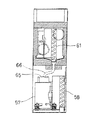
この冷却ユニット(51)は、図7、図8に示すように、圧縮機(57)と凝縮器(58)と蒸発器(61)とを連結して冷凍サイクル(56)を形成し、前記蒸発器(61)を断熱壁体(67)で形成した冷却室(71)内に収納するとともに、圧縮機(57)と凝縮器(58)とを機械室(55)内に配設し、前記冷却室(71)を機械室(55)の上部に載置することで冷凍サイクル(56)をユニット化しコンパクト化するとともに、これらの設置スペースを可能な限り小さくして据え付け安定性を良好にしたものである。
しかしながら、前記冷却ユニット(51)を床面に設置したマット部分に冷気を供給する空気循環式の寝具(76)に適用したような場合には、冷気を発生する冷却室(71)が機械室(55)の上部に位置していることから、この冷却室(71)から床面に設置したマットまで冷気を供給するためには長尺の送風ダクト(75)が必要となり、その分設置スペースが増加するだけでなく、部品材料が多くなり、コスト高になるとともに据え付け部における長尺のダクトの存在は外観を損なう不具合があった。 However, when the cooling unit (51) is applied to an air circulation bedding (76) for supplying cold air to a mat portion installed on the floor, the cooling chamber (71) for generating cold air is a machine room. Since it is located at the top of (55), a long air duct (75) is required to supply cool air from this cooling chamber (71) to the mat installed on the floor, and the installation space accordingly. In addition to an increase in the number of parts, there is a problem that the parts materials are increased, the cost is increased, and the presence of a long duct in the installation part impairs the appearance.
本発明は、上記の点を考慮してなされたものであり、冷却ユニットにおける冷却室と機械室とのレイアウトを変更することにより、冷却対象物と冷却室との距離を最短にして、設置スペースが小さく、安価に製造でき、外観的にも良好な冷却ユニットを提供することを目的とする。 The present invention has been made in consideration of the above points, and by changing the layout of the cooling chamber and the machine room in the cooling unit, the distance between the object to be cooled and the cooling chamber is minimized, and the installation space is provided. The object of the present invention is to provide a cooling unit that is small in size, can be manufactured at low cost, and has good appearance.
上記課題を解決するために本発明の冷却ユニットは、圧縮機と凝縮器と蒸発器とを環状に連結して形成した冷凍サイクルと、断熱壁体で形成され内部に前記蒸発器と冷却ファンを収納するとともに冷気の外部への吹き出し風路および戻り風路を形成した冷却室と、前記圧縮機と凝縮器とを配設した機械室とを備え、前記冷却室を機械室の下方に配置した冷却ユニットにおいて、蒸発器は、幅寸法及び高さ寸法が奥行き寸法に比べて大きく、冷却室の前面に沿わせ立設され、蒸発器の一端側の冷却室の側部に冷却ファンが設けられ、蒸発器の前方に吸い込み流路が設けられ、冷却ファンの前方に吹き出し流路が設けられ、吸い込み流路から吸い込んだ空気は、蒸発器の前面から後方へ流れ、冷却ファンによって前方へ向け吹き出し流路から吹き出されることを特徴とする冷却ユニット。 In order to solve the above problems, a cooling unit of the present invention includes a refrigeration cycle formed by annularly connecting a compressor, a condenser, and an evaporator, and an evaporator and a cooling fan formed in a heat insulating wall. A cooling chamber that houses and forms a blowout air path and a return air path to the outside of the cold air, and a machine room in which the compressor and the condenser are arranged, and the cooling room is arranged below the machine room In the cooling unit , the evaporator has a width dimension and a height dimension that are larger than the depth dimension, is erected along the front surface of the cooling chamber, and a cooling fan is provided on the side of the cooling chamber on one end side of the evaporator. A suction flow path is provided in front of the evaporator, and a blow-out flow path is provided in front of the cooling fan. Air sucked from the suction flow path flows rearward from the front of the evaporator and blows out forward by the cooling fan. Blowing from the flow path Cooling unit, characterized in that it is.
本発明によれば、床面に設置した空気循環式マットなどの冷却対象物と冷却室との距離を最短化することができるので、送風ダクトの長さの短縮、あるいはダクトの設置自体をなくすことができ、設置スペースの縮小とともに部品のコスト低減が可能となり、外観を良好に保つことができる。 According to the present invention, since the distance between the cooling object such as an air circulation mat installed on the floor and the cooling chamber can be minimized, the length of the air duct is shortened or the installation of the duct itself is eliminated. In addition, the installation space can be reduced and the cost of the parts can be reduced, and the appearance can be kept good.
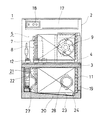
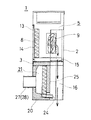
以下、図面に基づき本発明の1実施形態について説明する。冷却ユニット(1)の正面からの断面図である図1、および図1の側断面図である図2に示すように、薄鋼板製の外板(2)で横長の所定高さを有する箱体状の外郭を形成し、高さ方向のほぼ中央部を発泡スチロール成型体などからなる断熱仕切壁(3)で上下の空間に区分している。 Hereinafter, an embodiment of the present invention will be described with reference to the drawings. As shown in FIG. 1 which is a cross-sectional view from the front of the cooling unit (1) and FIG. 2 which is a side cross-sectional view of FIG. 1, the outer plate (2) made of a thin steel plate has a horizontally long predetermined height. A body-like outline is formed, and a substantially central portion in the height direction is divided into upper and lower spaces by a heat insulating partition wall (3) made of a foamed polystyrene molded body or the like.
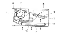
前記断熱仕切壁(3)の上方の空間には、冷凍サイクル(6)の一環をなす冷媒を圧縮して吐出する圧縮機(7)と、吐出された高温高圧の冷媒を受けて放熱し凝縮する凝縮器(8)およびこれら凝縮器(8)などの高温部品を冷却する放熱ファン(9)を剛性のある鋼板などで形成した仕切板(4)上に設置し、機械室(5)としている。 In the space above the heat insulating partition wall (3), the compressor (7) that compresses and discharges the refrigerant that forms part of the refrigeration cycle (6) and the discharged high-temperature and high-pressure refrigerant receive heat and condense. The condenser (8) and the heat dissipating fan (9) for cooling the high-temperature components such as the condenser (8) are installed on the partition plate (4) formed of a rigid steel plate or the like as the machine room (5) Yes.
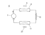
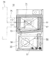
前記冷凍サイクル(6)は、図3に示すように、前記圧縮機(7)、凝縮器(8)、減圧器である毛細管(10)、および詳細を後述する蒸発器(11)を環状に連結して、圧縮機(7)の駆動により冷媒を循環し、蒸発器(11)で蒸発させることによって冷気を生成するものであり、前記機械室(5)内の横断面図である図4に示すように、重量物である圧縮機(7)は、前記底板(4)上の幅方向の一側に偏倚して振動吸収用のクッション体(12)を介して固着されている。 As shown in FIG. 3, the refrigeration cycle (6) has an annular configuration of the compressor (7), a condenser (8), a capillary tube (10) as a decompressor, and an evaporator (11) whose details will be described later. FIG. 4 is a cross-sectional view of the inside of the machine room (5), in which the refrigerant is circulated by the drive of the compressor (7), and cool air is generated by evaporating in the evaporator (11). As shown in FIG. 2, the compressor (7), which is a heavy object, is biased to one side in the width direction on the bottom plate (4) and fixed through a vibration absorbing cushion body (12).
蛇行曲げした冷媒管を多数のフィンに嵌入させて奥行き寸法を薄くした直方体状の凝縮器(8)は、面積の大きなその前面を外板(2)の前面に形成した吸込み開口(13)に沿わせて立設させ、この吸込み開口(13)と凝縮器(8)との間には埃などを遮蔽するためにフィルター(14)を設けている。 The rectangular parallelepiped condenser (8) in which the meandering refrigerant pipe is inserted into a large number of fins to reduce the depth dimension is formed in a suction opening (13) formed on the front surface of the outer plate (2) with its front surface having a large area. A filter (14) is provided between the suction opening (13) and the condenser (8) to shield dust and the like.
凝縮器(8)の背面には、前記圧縮機(7)の運転に同期して駆動する放熱ファン(9)を前記圧縮機(7)に対向する平面における1コーナーの底部に開口した排気口(15)の端縁に面して立設させており、駆動時には、外気を前面の開口(13)から内部に吸引して凝縮器(8)を冷却し、熱交換した空気を外板(2)の前記排気口(15)から下方の排気ダクト(16)に向けて放出するようにしている。 On the back surface of the condenser (8), a heat radiating fan (9) driven in synchronism with the operation of the compressor (7) is opened at the bottom of one corner in a plane facing the compressor (7). (15) is erected facing the edge, and during driving, outside air is sucked into the front through the opening (13) to cool the condenser (8), and the heat exchanged air is removed from the outer plate ( It is discharged from the exhaust port (15) of 2) toward the lower exhaust duct (16).
このとき、前述したように、圧縮機(7)は機械室(5)内の側部に偏倚しているため放熱ファン(9)による冷却作用を直接受けないようにしており、過冷却による蒸発温度を低下を防いでいるとともに、偏倚している分奥行き方向で放熱ファン(9)と圧縮機(7)が重ならないように配置することで、機械室(5)の奥行き寸法の短縮化をはかっている。 At this time, as described above, since the compressor (7) is biased to the side portion in the machine room (5), the compressor (7) is not directly subjected to the cooling action by the heat radiating fan (9). The temperature of the machine room (5) can be reduced by preventing the temperature from decreasing and arranging the heat dissipation fan (9) and the compressor (7) so that they do not overlap in the depth direction. It's striking.
そして、前記機械室(5)の上部には、PC基板上にDC−ACインバータを収納した幅方向に長い筒状の電装室(17)を区画して配設するとともに、その前面には操作パネル(18)を配置して冷却ユニット(1)の運転を制御するようにしている。 In the upper part of the machine room (5), a cylindrical electrical room (17) which is long in the width direction and accommodates a DC-AC inverter is arranged on a PC board, and an operation is provided on the front surface thereof. A panel (18) is arranged to control the operation of the cooling unit (1).
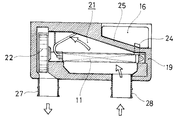
しかして、前記断熱仕切壁(3)の下方空間には、前記断熱仕切壁(3)に連なるように同様の材料で形成された断熱側壁(19)を外板(2)の内面側に配設し、底部には剛性のある断熱壁(20)を設けることで内部を断熱空間とした冷却室(21)を設置しており、図5の横断面図で示すように、その中央部から前方の部分には、前記凝縮器(8)からの冷媒を受けてこれを蒸発させることで低温化した冷気を生成する蒸発器(11)を冷却室(21)の幅方向に亙って立設状態で配置している。 Therefore, in the space below the heat insulating partition wall (3), a heat insulating side wall (19) formed of the same material so as to be continuous with the heat insulating partition wall (3) is arranged on the inner surface side of the outer plate (2). A cooling chamber (21) with a heat insulating space inside is provided by providing a rigid heat insulating wall (20) at the bottom, and as shown in the cross-sectional view of FIG. In the front part, an evaporator (11) that generates a low-temperature cold by receiving the refrigerant from the condenser (8) and evaporating the refrigerant is provided across the width of the cooling chamber (21). It is arranged in the installed state.
この蒸発器(11)も前記凝縮器(8)と同様に、蛇行曲げした冷媒管と冷媒管に嵌着した多数のフィンとから所定の幅と高さ寸法を有して奥行き寸法を薄くした横長の直方体を形成しており、前記蒸発器(11)の一端側の冷却室(21)の側部、すなわち、図5中の左側には、シロッコファンからなる冷却ファン(22)を蒸発器(11)の長手方向に直交するように、冷却室(21)の奥行き方向に亙り、立設させて併置している。 Similarly to the condenser (8), the evaporator (11) has a predetermined width and height dimension and a reduced depth dimension from a meandering bent refrigerant pipe and a large number of fins fitted to the refrigerant pipe. A horizontally long rectangular parallelepiped is formed, and a cooling fan (22) made of a sirocco fan is placed on the side of the cooling chamber (21) on one end side of the evaporator (11), that is, on the left side in FIG. In the depth direction of the cooling chamber (21) so as to be orthogonal to the longitudinal direction of (11), the cooling chamber (21) is erected and juxtaposed.
前記蒸発器(11)の下面に対応する冷却室(21)の底面には、一側に向かって下方傾斜させた露受け樋(23)を形成しており、この露受け樋部(23)によって、冷却運転時に蒸発器(11)に付着する霜の融解水を集めるようにしている。集められたドレン水は、露受け樋(23)の傾斜下端部と前記排気ダクト(16)とを連通するように形成した排水路(24)を流下し、排気ダクト(16)から外部に流出する。 On the bottom surface of the cooling chamber (21) corresponding to the lower surface of the evaporator (11), a dew receiving bowl (23) inclined downward toward one side is formed, and this dew receiving bowl section (23) Therefore, the frost melting water adhering to the evaporator (11) during the cooling operation is collected. The collected drain water flows down the drainage channel (24) formed so as to connect the lower end of the slope of the dew catcher (23) and the exhaust duct (16), and flows out from the exhaust duct (16). To do.
前記排気ダクト(16)は、冷却室(21)をその平面からみた状態で、前記機械室(5)の底部に開口させた前記排気口(15)に対応する断熱仕切壁(3)、断熱側壁(19)および底面の断熱壁(20)の1コーナー部、本実施例では右奥のコーナー部を内方に凹陥させて形成した凹陥部(25)と前記排気口(15)とによって設けられたものであり、上方に位置する機械室(5)から本体底面まで貫通させることで、冷却ユニット(1)の駆動時には、凝縮器(8)や圧縮機(7)と熱交換して温度上昇した空気を前記放熱ファン(9)の回転により下方に流下させ、外気中に放出するようにしている。 The exhaust duct (16) includes a heat insulating partition wall (3) corresponding to the exhaust port (15) opened at the bottom of the machine room (5) in a state where the cooling chamber (21) is viewed from the plane, One corner of the side wall (19) and the heat insulating wall (20) on the bottom surface, in this embodiment is provided by a recess (25) formed by recessing inwardly the corner at the back right and the exhaust port (15). By passing through the machine room (5) located above from the bottom of the main body, when the cooling unit (1) is driven, heat is exchanged with the condenser (8) and the compressor (7). The raised air is caused to flow downward by the rotation of the heat dissipating fan (9) and discharged into the outside air.
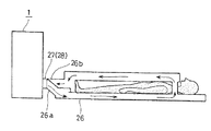
冷却室(19)における前記冷却ファン(22)の設置部の前方には、ファンケーシングによって連結され、冷却対象物、例えば、図6に示す冷却ユニット(1)の前面側に相対向して配置した空気循環式の冷却マット(26)の空洞内部に冷気を導入するようにその冷気取り入れ口(26a)に連結した円筒状の吹き出し風路(27)を外方に突出させている。また、この吹き出し風路(27)の幅方向の反対側に位置する前記蒸発器(11)の前面には、戻り風路(28)を前記吹き出し風路(27)と同様に突出させて設けており、前記冷却マット(26)内を循環冷却した冷気を戻り口(26b)から前記戻り風路(28)を介して冷却室(21)内の前記蒸発器(11)の一端側に流入させるようにしている。 The cooling fan (22) is connected to the front side of the cooling fan (22) in the cooling chamber (19) by a fan casing and is opposed to the object to be cooled, for example, the front side of the cooling unit (1) shown in FIG. A cylindrical blowing air passage (27) connected to the cold air intake (26a) is projected outward so as to introduce cold air into the cavity of the air circulation type cooling mat (26). Further, a return air passage (28) is provided on the front surface of the evaporator (11) located on the opposite side of the blowing air passage (27) in the width direction so as to protrude in the same manner as the blowing air passage (27). The cold air circulated and cooled in the cooling mat (26) flows into the one end side of the evaporator (11) in the cooling chamber (21) from the return port (26b) through the return air passage (28). I try to let them.
以上の構成により、冷却ユニット(1)における圧縮機(7)を運転した場合には、凝縮器(8)からの冷媒を蒸発させることで蒸発器(11)を低温化して冷却室(21)内の空気を冷却し、生成された冷気を冷却ファン(20)によって吹き出し風路(31)から冷却マット(25)などの冷却対象物に吹き出してこれを冷却するものであり、循環後は戻り風路(28)から冷却室(19)内の蒸発器(11)に流入させ、再び冷却して吹き出す冷気循環を繰り返す。 With the above configuration, when the compressor (7) in the cooling unit (1) is operated, the evaporator (11) is lowered in temperature by evaporating the refrigerant from the condenser (8) to cool the cooling chamber (21). The inside air is cooled, and the generated cooling air is blown out from the blowing air passage (31) to the cooling object such as the cooling mat (25) by the cooling fan (20) to cool it. The cold air circulation is repeated by flowing into the evaporator (11) in the cooling chamber (19) from the air passage (28) and cooling again.
したがって、従来の冷却室(71)を機械室(55)の上方に配置する構成に比して、冷却室(21)を機械室(5)の下方に配設したので、前記図6に示すように、冷却室(21)からの冷気の吹き出し風路(27)や戻り風路(28)の位置が冷却ユニット(1)の低部となり、特に、冷却対象物が前記空気循環式の冷却マット(26)などのように床面近傍に配置するものの場合は、その接続構成がきわめて容易となり、熱損失が少ないので冷気の伝達効率を向上させることができる。また、床面近傍に設置した冷却マット(26)の冷気取り入れ口(26a)や戻り口(26b)と前記冷気吹き出し風路(27)や戻り風路(28)とを直接連結することができるので、長尺のダクト部材が不必要になり、ダクトスペースを削減できるばかりか、部品数やコストアップを抑制でき、ダクト部材が突出しないので外観を良好に保つことができる。 Accordingly, the cooling chamber (21) is disposed below the machine chamber (5) as compared with the conventional configuration in which the cooling chamber (71) is disposed above the machine chamber (55). As described above, the position of the blowout air passage (27) and the return air passage (28) for cooling air from the cooling chamber (21) is the lower part of the cooling unit (1), and in particular, the object to be cooled is the air circulation type cooling device. In the case of the mat (26) or the like arranged near the floor surface, the connection configuration is very easy and the heat loss is small, so that the transmission efficiency of cold air can be improved. Further, the cold air intake (26a) and the return port (26b) of the cooling mat (26) installed in the vicinity of the floor surface can be directly connected to the cold air blowing air channel (27) and the return air channel (28). Therefore, a long duct member becomes unnecessary, and not only the duct space can be reduced, but also the number of parts and cost increase can be suppressed, and the duct member does not protrude, so that the appearance can be kept good.
上記のように、機械室(5)においては、凝縮器(8)や圧縮機(7)の配設位置に対向するコーナー部に排気口(15)を、冷却室(21)においては、蒸発器(11)やこの蒸発器(11)の長手方向と直交する側部に配置した冷却ファン(22)と対向するコーナー部に凹陥部(25)をそれぞれ設けることによって排気ダクト(16)を形成したので、各室(5)(21)への効果的な部品配置により生み出したスペース空間を活用して大きな排気スペースとすることができ、放熱効率を高くして冷凍サイクル(6)の効率を向上できるとともに、冷却ユニット(1)としての外形を最小レベルまでコンパクト化でき、設置スペースの縮小が可能となるものである。 As described above, in the machine room (5), the exhaust port (15) is provided at the corner opposite to the position where the condenser (8) and the compressor (7) are disposed, and in the cooling room (21), the evaporation is performed. An exhaust duct (16) is formed by providing recesses (25) at the corners facing the cooling fan (22) placed on the side perpendicular to the longitudinal direction of the evaporator (11) and the evaporator (11). Therefore, it is possible to make a large exhaust space by utilizing the space created by the effective component placement in each chamber (5) (21), and to improve the efficiency of the refrigeration cycle (6) by increasing the heat dissipation efficiency. In addition to being improved, the outer shape of the cooling unit (1) can be reduced to the minimum level, and the installation space can be reduced.
特に、前記構成においては、冷却ファン(22)を蒸発器(11)の長手方向の一端側に直交して配置していることから、冷却ファン(22)の径寸法を冷却室(21)の奥行き長さに合わせてその側部に設置することができ、その分他のスペースを活用できるので、冷却ファン(22)に対向する1コーナー部に排気ダクト(16)を形成する凹陥部(25)をより拡大した状態で容易に設けることができるものである。 In particular, in the above configuration, since the cooling fan (22) is arranged orthogonal to one end side in the longitudinal direction of the evaporator (11), the diameter of the cooling fan (22) is set to be equal to that of the cooling chamber (21). It can be installed on its side to match the depth, and other space can be used accordingly, so that the recess (25) that forms the exhaust duct (16) at one corner that faces the cooling fan (22) ) Can be easily provided in an enlarged state.
また、前記蒸発器(11)の露水を受ける露受け樋(22)と集められたドレン水を排気ダクト(16)に導く排水路(24)により、機械室(5)内の排気と冷却室(21)内のドレン水とを排気ダクト(16)を介して外部に流出させることができるので、従来のように、圧縮機(57)の上部に設けたドレン蒸発装置(65)が不要になるとともに、露受け樋(73)と前記蒸発装置(65)とを連結するドレンホース(66)などの部品配置が不要となり、スペース削減効果が大きくなるばかりでなく、部品数や製造工数削減によるコスト低減に寄与できる。 Also, the exhaust and cooling chamber in the machine room (5) are provided by a dew receiving bowl (22) that receives the dew water from the evaporator (11) and a drainage channel (24) that guides the collected drain water to the exhaust duct (16). Because the drain water in (21) can be discharged to the outside through the exhaust duct (16), the drain evaporator (65) provided on the top of the compressor (57) is unnecessary as in the past. In addition, the arrangement of parts such as the drain hose (66) that connects the dew receiving bowl (73) and the evaporator (65) is not required, which not only increases the space reduction effect, but also reduces the number of parts and manufacturing man-hours. This can contribute to cost reduction.
さらに、前記のように排気ダクト(16)を構成する凹陥部(25)は、前記機械室(5)に配置した圧縮機(7)および凝縮器(8)から導出した配管と下方の蒸発器(11)からの延出管とを接続する配管スペースとしても利用することができ、このようにすれば、外板(2)の外部空間に接続スペースを設ける必要がなく、冷却ユニット(1)自体の外形寸法の拡大を防ぐ効果を有する。 Further, as described above, the recessed portion (25) constituting the exhaust duct (16) is provided with a pipe led out from the compressor (7) and the condenser (8) disposed in the machine room (5) and a lower evaporator. It can also be used as a piping space for connecting the extension pipe from (11), and in this way, there is no need to provide a connection space in the external space of the outer plate (2), and the cooling unit (1) It has the effect of preventing the expansion of its external dimensions.
なお、前記冷却対象物としての前記冷却マット(26)は、内部の空洞内に冷気を導入することにより、その上部や内部に入る人体を冷却するものであるが、冷却対象物はこれに限るものではなく、その形態や設置スペースから、冷却ユニットと冷却対象物とが一体化できない構成のものであればよく、断熱箱体の内部に冷気を導入して収納されている食品などを冷却する冷却貯蔵庫としてもよい。また、小部屋や室内の一部の空気冷却に用いることを目的としたスポットクーラーでもよく、さらに、これらの冷却対象物を戸外で使用する場合を考慮すれば、電源は、交流電源に限らず電池を使用するようにしてもよい。 The cooling mat (26) as the object to be cooled is for cooling the human body entering the upper part or inside by introducing cool air into the internal cavity, but the object to be cooled is limited to this. The cooling unit and the object to be cooled need only be configured so that the cooling unit and the object to be cooled cannot be integrated from its form and installation space, and cools food stored by introducing cold air into the heat insulation box. It is good also as a cooling storage. Moreover, a spot cooler intended to be used for air cooling of a small room or a part of the room may be used. Further, considering the case where these objects to be cooled are used outdoors, the power source is not limited to an AC power source. A battery may be used.
1 冷却ユニット 2 外板 3 断熱仕切壁
4 仕切板 5 機械室 6 冷凍サイクル
7 圧縮機 8 凝縮器 9 放熱ファン
11 蒸発器 13 吸込み開口 14 フィルター
15 排気口 16 排気ダクト 17 電装室
19 断熱側壁 20 断熱壁 21 冷却室
22 冷却ファン 23 露受け樋 24 排水路
25 凹陥部 26 冷却マット 26a 冷気取り入れ口
26b 戻り口 27 吹き出し風路 28 戻り風路
DESCRIPTION OF
11
15
19
22 Cooling
25 Recessed
Claims (5)
蒸発器は、幅寸法及び高さ寸法が奥行き寸法に比べて大きく、冷却室の前面に沿わせ立設され、蒸発器の一端側の冷却室の側部に冷却ファンが設けられ、蒸発器の前方に吸い込み流路が設けられ、冷却ファンの前方に吹き出し流路が設けられ、吸い込み流路から吸い込んだ空気は、蒸発器の前面から後方へ流れ、冷却ファンによって前方へ向け吹き出し流路から吹き出されることを特徴とする冷却ユニット。 A refrigeration cycle formed by annularly connecting a compressor, a condenser, and an evaporator, and an evaporator and a cooling fan that are formed in a heat insulating wall and housed therein, and a blowout air path and return air to the outside of the cold air a cooling chamber which is formed a road, and a condenser and a mechanical chamber which is disposed between the compressor, the cooling unit which is disposed below the machine room of the cooling chamber,
The evaporator has a width dimension and a height dimension that are larger than the depth dimension, is erected along the front surface of the cooling chamber, and is provided with a cooling fan on the side of the cooling chamber on one end side of the evaporator. A suction flow path is provided in front, and a blow-off flow path is provided in front of the cooling fan. Air sucked from the suction flow path flows from the front of the evaporator to the rear, and is blown forward from the blow-off flow path by the cooling fan. A cooling unit.
前記凹陥部の蒸発器と対向する面が、冷却ファン側に行くほど後方へ傾斜する傾斜面をなしていることを特徴とする請求項2記載の冷却ユニット。 The cooling unit according to claim 2, wherein a surface of the recessed portion that faces the evaporator forms an inclined surface that is inclined rearward toward the cooling fan side.
Priority Applications (1)
| Application Number | Priority Date | Filing Date | Title |
|---|---|---|---|
| JP2008103651A JP5259235B2 (en) | 2008-04-11 | 2008-04-11 | Cooling unit |
Applications Claiming Priority (1)
| Application Number | Priority Date | Filing Date | Title |
|---|---|---|---|
| JP2008103651A JP5259235B2 (en) | 2008-04-11 | 2008-04-11 | Cooling unit |
Publications (2)
| Publication Number | Publication Date |
|---|---|
| JP2009257598A JP2009257598A (en) | 2009-11-05 |
| JP5259235B2 true JP5259235B2 (en) | 2013-08-07 |
Family
ID=41385250
Family Applications (1)
| Application Number | Title | Priority Date | Filing Date |
|---|---|---|---|
| JP2008103651A Expired - Fee Related JP5259235B2 (en) | 2008-04-11 | 2008-04-11 | Cooling unit |
Country Status (1)
| Country | Link |
|---|---|
| JP (1) | JP5259235B2 (en) |
Families Citing this family (1)
| Publication number | Priority date | Publication date | Assignee | Title |
|---|---|---|---|---|
| KR101206507B1 (en) | 2010-12-08 | 2012-11-29 | (주)부성 | Refrigerator with a withdrawable cooling unit |
Family Cites Families (10)
| Publication number | Priority date | Publication date | Assignee | Title |
|---|---|---|---|---|
| JPS4429496Y1 (en) * | 1967-06-27 | 1969-12-05 | ||
| JPS5467261A (en) * | 1977-11-09 | 1979-05-30 | Hitachi Ltd | Refrigerating machine for refrigerator |
| JPS5854103Y2 (en) * | 1981-08-10 | 1983-12-09 | 正和 松本 | Bedding with water cooler |
| JPS58140582A (en) * | 1982-02-17 | 1983-08-20 | 株式会社日立製作所 | Evaporator of refrigerator for loading on car |
| JPS6062582A (en) * | 1984-07-30 | 1985-04-10 | 株式会社日立製作所 | refrigerator |
| JP3741833B2 (en) * | 1997-08-07 | 2006-02-01 | ホシザキ電機株式会社 | refrigerator |
| JP2003065651A (en) * | 2001-08-21 | 2003-03-05 | Hoshizaki Electric Co Ltd | Refrigerating unit |
| JP2006329554A (en) * | 2005-05-27 | 2006-12-07 | Matsushita Electric Ind Co Ltd | Cooling unit |
| JP2007098044A (en) * | 2005-10-07 | 2007-04-19 | Twinbird Corp | sleeping bag |
| JP2009002596A (en) * | 2007-06-22 | 2009-01-08 | Toshiba Corp | Cooling unit |
-
2008
- 2008-04-11 JP JP2008103651A patent/JP5259235B2/en not_active Expired - Fee Related
Also Published As
| Publication number | Publication date |
|---|---|
| JP2009257598A (en) | 2009-11-05 |
Similar Documents
| Publication | Publication Date | Title |
|---|---|---|
| JP2007309608A (en) | Trailer refrigeration equipment | |
| JP2005098559A (en) | refrigerator | |
| JPH07146054A (en) | refrigerator | |
| JP4473788B2 (en) | refrigerator | |
| JP2006138609A (en) | refrigerator | |
| CN104380015B (en) | refrigerator | |
| JP5259271B2 (en) | Cooling unit | |
| JP5259235B2 (en) | Cooling unit | |
| JP2009002596A (en) | Cooling unit | |
| JP2009185775A (en) | Cooling unit | |
| JP2014066494A (en) | Refrigerator | |
| JP2003042636A (en) | refrigerator | |
| JP2003287342A (en) | refrigerator | |
| JP2008111664A (en) | refrigerator | |
| JP3855143B2 (en) | refrigerator | |
| JP2012255638A (en) | Refrigerator | |
| JPH0791811A (en) | refrigerator | |
| JP2008292093A (en) | refrigerator | |
| JP2001324174A (en) | Freezer unit | |
| KR101202872B1 (en) | Machine room for refrigerator | |
| JP3954829B2 (en) | Heat exchanger, heat exchange unit and cooling storage | |
| JP2009192147A (en) | Cooling unit | |
| JP4621567B2 (en) | refrigerator | |
| JP4156952B2 (en) | Cooling storage | |
| WO2010098049A1 (en) | Temperature adjusting device for mounting on vehicle |
Legal Events
| Date | Code | Title | Description |
|---|---|---|---|
| A621 | Written request for application examination |
Free format text: JAPANESE INTERMEDIATE CODE: A621 Effective date: 20110316 |
|
| A977 | Report on retrieval |
Free format text: JAPANESE INTERMEDIATE CODE: A971007 Effective date: 20120831 |
|
| A131 | Notification of reasons for refusal |
Free format text: JAPANESE INTERMEDIATE CODE: A131 Effective date: 20120911 |
|
| A521 | Written amendment |
Free format text: JAPANESE INTERMEDIATE CODE: A523 Effective date: 20121109 |
|
| TRDD | Decision of grant or rejection written | ||
| A01 | Written decision to grant a patent or to grant a registration (utility model) |
Free format text: JAPANESE INTERMEDIATE CODE: A01 Effective date: 20130402 |
|
| A61 | First payment of annual fees (during grant procedure) |
Free format text: JAPANESE INTERMEDIATE CODE: A61 Effective date: 20130424 |
|
| FPAY | Renewal fee payment (event date is renewal date of database) |
Free format text: PAYMENT UNTIL: 20160502 Year of fee payment: 3 |
|
| R150 | Certificate of patent or registration of utility model |
Free format text: JAPANESE INTERMEDIATE CODE: R150 |
|
| LAPS | Cancellation because of no payment of annual fees |