JP5259192B2 - Nail plate system - Google Patents
Nail plate system Download PDFInfo
- Publication number
- JP5259192B2 JP5259192B2 JP2007553293A JP2007553293A JP5259192B2 JP 5259192 B2 JP5259192 B2 JP 5259192B2 JP 2007553293 A JP2007553293 A JP 2007553293A JP 2007553293 A JP2007553293 A JP 2007553293A JP 5259192 B2 JP5259192 B2 JP 5259192B2
- Authority
- JP
- Japan
- Prior art keywords
- implant
- head portion
- nail
- screw
- hole
- Prior art date
- Legal status (The legal status is an assumption and is not a legal conclusion. Google has not performed a legal analysis and makes no representation as to the accuracy of the status listed.)
- Expired - Fee Related
Links
- 239000007943 implant Substances 0.000 claims description 73
- 210000000988 bone and bone Anatomy 0.000 claims description 61
- 208000010392 Bone Fractures Diseases 0.000 claims description 29
- 238000002513 implantation Methods 0.000 claims description 26
- 210000002758 humerus Anatomy 0.000 claims description 24
- 210000003275 diaphysis Anatomy 0.000 claims description 5
- 230000007423 decrease Effects 0.000 claims description 3
- 206010017076 Fracture Diseases 0.000 description 31
- 238000000034 method Methods 0.000 description 25
- 206010020462 Humerus fracture Diseases 0.000 description 9
- 230000001054 cortical effect Effects 0.000 description 9
- 210000001519 tissue Anatomy 0.000 description 9
- 208000007981 Humeral Fractures Diseases 0.000 description 8
- 210000004095 humeral head Anatomy 0.000 description 6
- NJPPVKZQTLUDBO-UHFFFAOYSA-N novaluron Chemical compound C1=C(Cl)C(OC(F)(F)C(OC(F)(F)F)F)=CC=C1NC(=O)NC(=O)C1=C(F)C=CC=C1F NJPPVKZQTLUDBO-UHFFFAOYSA-N 0.000 description 6
- 230000000399 orthopedic effect Effects 0.000 description 4
- 238000005452 bending Methods 0.000 description 3
- 230000008901 benefit Effects 0.000 description 3
- 230000008878 coupling Effects 0.000 description 3
- 238000010168 coupling process Methods 0.000 description 3
- 238000005859 coupling reaction Methods 0.000 description 3
- 238000005553 drilling Methods 0.000 description 3
- 238000003754 machining Methods 0.000 description 3
- 230000002441 reversible effect Effects 0.000 description 3
- 241000237503 Pectinidae Species 0.000 description 2
- 238000005516 engineering process Methods 0.000 description 2
- 238000003780 insertion Methods 0.000 description 2
- 230000037431 insertion Effects 0.000 description 2
- 230000004048 modification Effects 0.000 description 2
- 238000012986 modification Methods 0.000 description 2
- 210000005036 nerve Anatomy 0.000 description 2
- 230000036961 partial effect Effects 0.000 description 2
- 230000008569 process Effects 0.000 description 2
- 230000009467 reduction Effects 0.000 description 2
- 235000020637 scallop Nutrition 0.000 description 2
- 210000002659 acromion Anatomy 0.000 description 1
- 210000003484 anatomy Anatomy 0.000 description 1
- 230000005540 biological transmission Effects 0.000 description 1
- 230000037182 bone density Effects 0.000 description 1
- 230000008859 change Effects 0.000 description 1
- 230000003247 decreasing effect Effects 0.000 description 1
- 238000002594 fluoroscopy Methods 0.000 description 1
- 230000003100 immobilizing effect Effects 0.000 description 1
- 208000014674 injury Diseases 0.000 description 1
- 230000002452 interceptive effect Effects 0.000 description 1
- 230000002829 reductive effect Effects 0.000 description 1
- 230000008733 trauma Effects 0.000 description 1
Images


Description
〔発明の背景〕
〔発明の分野〕
本発明は、概して、手術機器に関する。より具体的には、本発明は、整形外科用骨折部固定システムおよび整形外科用骨折部固定システムを植え込むための器具に関する。
BACKGROUND OF THE INVENTION
(Field of the Invention)
The present invention relates generally to surgical instruments. More specifically, the present invention relates to orthopedic fracture fixation systems and instruments for implanting orthopedic fracture fixation systems.
〔最新技術〕
上腕骨近位部は、一般に肩領域として知られている上腕骨の上側の部分、つまり、人体の上腕を含んでいる。上腕骨近位部の骨折は、通常、運動中の事故のような外傷によって生じるものであり、骨密度が減るために、年齢とともに頻度が増えることがある。上腕骨近位部の骨折は、骨折部位を露出させ、骨の破損を整復し、骨の比較的大きな領域にわたってプレートを配置し、骨折部が整復された位置で治癒するよう動かなくすることで治療する。骨折の整復は、骨の骨折した部位をその元の位置、または、似たような安定した位置に合わせ直して、位置付けすることを含む。骨折部の固定には、プレートを骨折した部分の上に配置し、そのプレートを骨折した骨と、隣接する骨折していない骨とに骨ネジで固定することが含まれる。
〔latest technology〕
The proximal humerus includes the upper part of the humerus, commonly known as the shoulder region, that is, the upper arm of the human body. Fractures at the proximal humerus are usually caused by trauma such as an accident during exercise and may increase in frequency with age due to decreased bone density. Fractures in the proximal humerus can be achieved by exposing the fracture site, reducing bone damage, placing a plate over a relatively large area of the bone, and immobilizing the fracture to heal in the reduced position. treat. Fracture reduction involves repositioning the fractured portion of the bone to its original or similar stable position. Fixing the fracture includes placing the plate over the fractured portion and fixing the plate to the fractured bone and the adjacent unbroken bone with a bone screw.
従来の固定プレートには、上腕骨近位部に利用した場合に、いくつかの欠点がある。一般に、従来の固定プレートは、その外形が上腕骨の解剖学的構造に十分に合わせたものではなく、上腕骨の骨折を安定化させるための構造的な剛性を得るのに必要なサイズで提供されると、形を合わせることが外科医に取って容易ではない。さらに、従来の固定プレートでは、そのプレートを配置し固定するために相当量の組織を露出させ、移動させることが必要である。 Conventional fixation plates have several drawbacks when used in the proximal humerus. In general, traditional fixation plates are not well-tuned to the humeral anatomy and are provided in the size required to provide structural rigidity to stabilize humeral fractures Once done, it is not easy for the surgeon to adjust the shape. Furthermore, conventional fixation plates require that a substantial amount of tissue be exposed and moved in order to place and fix the plate.
〔発明の概要〕
そこで本発明の課題は、解剖学的に上腕骨のために適した上腕骨骨折部固定システムを提供することである。
[Summary of the Invention]
Accordingly, an object of the present invention is to provide a humeral fracture fixing system that is anatomically suitable for the humerus.
本発明の別の課題は、上腕骨近位部の骨折部を支持する安定した枠を提供する上腕骨骨折部固定システムを提供することである。 Another object of the present invention is to provide a humeral fracture fixation system that provides a stable frame for supporting the fracture of the proximal humerus.
本発明のさらなる課題は、多量の組織を移動させる必要のない上腕骨骨折部固定システムを提供することである。 It is a further object of the present invention to provide a humeral fracture fixation system that does not require movement of large amounts of tissue.
本発明のさらなる課題は、比較的低侵襲性の上腕骨骨折部固定システムを提供することである。 It is a further object of the present invention to provide a relatively minimally invasive humeral fracture fixation system.
本発明のさらに別の課題は、固定装置の位置を上腕骨骨幹部に合わせることが容易であり、固定具の位置を上腕骨の頭部に合わせることが容易である上腕骨骨折部固定システムを提供することである。 Still another object of the present invention is to provide a humerus fracture fixing system in which it is easy to adjust the position of the fixing device to the humeral shaft and to easily adjust the position of the fixing device to the head of the humerus. Is to provide.
本発明のさらに別の課題は、周囲組織を刺激しない上腕骨骨折部固定システムを提供することである。 Yet another object of the present invention is to provide a humeral fracture fixation system that does not irritate surrounding tissue.
本発明のさらに別の目的は、上腕骨骨折部固定システムを植え込むための器具を提供することである。 Yet another object of the present invention is to provide an instrument for implanting a humeral fracture fixation system.
以下に詳述するこれらの課題によれば、上腕骨骨折部固定システムが提供され、このシステムは、釘プレート固定装置を含んでおり、この釘プレート固定装置は、プレート状頭部部分、髄内釘部分、ならびに、プレート状頭部部分と髄内釘部分との間にある湾曲首部分を有し、この湾曲部分は、プレートと釘部分との間に所定の角度を形成する。 In accordance with these issues described in detail below, a humeral fracture fixation system is provided, which includes a nail plate fixation device, the nail plate fixation device comprising a plate-like head portion, an intramedullary portion. A nail portion and a curved neck portion between the plate-like head portion and the intramedullary nail portion, the curved portion forming a predetermined angle between the plate and the nail portion.
釘部分の上面は、実質的に真っ直ぐであり、下部は寸法がしだいに細くなっている。釘部分にはコーティカルスクリュー用孔(cortical screw hole)を含み、このコーティカルスクリュー用孔には、好ましくは、機械ねじ山を有するねじのねじ山付きシャフトを収容するための機械ねじ山が設けられている。 The upper surface of the nail portion is substantially straight and the lower portion is increasingly narrowed in size. The nail portion includes a cortical screw hole, which is preferably provided with a mechanical thread for receiving a threaded shaft of a screw having a mechanical thread. It has been.
頭部部分は、角度固定型固定ペグまたは固定ねじを収容するための固定用孔、および、Kワイヤ位置合わせ用孔を含む。頭部部分の前部は、縫合用孔を含む。好ましくは、これらの縫合用孔はトンネル状であり、湾曲した縫合用針によりアクセス可能である。好ましい実施形態では、3つのトンネル、すなわち、頭部部分の近位−遠位軸線に対して垂直であり、頭部部分の中央平面を介して延びる第1中央トンネルと、この第1中央トンネルの両側にあり、第1トンネルに対して約45°±15°の角度で位置している第2および第3のトンネルとが設けられている。本発明によれば、頭部部分の上側および前側の外形にはスカラップ(scallops)や突出部がなく、縫合用孔があることにより、実際に影響されることはない。滑らかな前端部の利点は、頭部部分を横切って移動する組織に対して横方向の抵抗がないことである。 The head portion includes a fixing hole for receiving a fixed-angle fixing peg or a fixing screw, and a K-wire alignment hole. The front portion of the head portion includes a suture hole. Preferably, these suture holes are tunnel-shaped and are accessible by a curved suture needle. In a preferred embodiment, there are three tunnels: a first central tunnel perpendicular to the proximal-distal axis of the head portion and extending through the central plane of the head portion; Second and third tunnels are provided on both sides and located at an angle of about 45 ° ± 15 ° with respect to the first tunnel. According to the present invention, there is no scallops or protrusions on the upper and front outlines of the head portion, and there is no actual influence due to the presence of the stitching holes. The advantage of a smooth front end is that there is no lateral resistance to the tissue moving across the head portion.
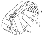
装置、特に頭部部分に連結できる植え込み用ジグもまた提供されている。このジグは、釘プレートの頭部部分の前端部にある引っ掛け部および固定用ねじによって頭部部分に取り付けられる。この引っ掛け部は、プレートの前端部にある3つの縫合用孔の間にある2つの溝によって形成されている。この溝は、縫合用の針をトンネルに入れることをも可能にする。 An implantable jig that can be coupled to the device, particularly the head portion, is also provided. The jig is attached to the head portion by a hook and a fixing screw at the front end of the head portion of the nail plate. This hook is formed by two grooves between three stitching holes at the front end of the plate. This groove also allows the suture needle to enter the tunnel.
ジグのハンドルは、釘部分から離れる方向に向けられた第1の位置、または、ハンドルが釘部分の一部の上に重なる第2の位置に、位置することができる。第1の位置では、ハンドルは、プレートを骨に挿入するのに用いられ、第2の位置では、ハンドルは、コーティカルスクリューのための孔をあけるのに用いられる。 The jig handle may be located in a first position directed away from the nail portion or in a second position where the handle overlies a portion of the nail portion. In the first position, the handle is used to insert the plate into the bone, and in the second position, the handle is used to drill a hole for the cortical screw.
コーティカルスクリューを植え込むためのシステムが提供されており、このシステムは、ねじ案内用カニューレ、ドリル案内用カニューレ、および、栓子を含んでいる。これらの3つのユニットは、組み合わせると、しだいに細くなる端部を形成し、この端部は、これら3つのユニットが、皮膚の小さな切開部に挿入され、組織を骨まで切断することを可能にする。その後、栓子は引き抜かれ、ドリルが導入され、皮質に孔をあけるのに用いられる。ドリルガイドは、その後、引き抜かれ、ねじが導入され、摩擦によってドライバに取り付けられる。ねじ案内用は、内径が一定であり、この内径は、遠位端だけを除く全体が、ねじの頭部にとってちょうど十分な大きさをしている。ねじ案内用の遠位端において、この直径はねじの頭部よりほんの少し小さい。これは、たとえば、(i)ねじ頭と若干干渉するように、この領域で(例えば機械加工により)小さな縁部を残すことにより、または、(ii)例えばスリット部の助けを借りてまたは借りずに、端部を内側に曲げることにより行う。本発明によれば、ねじの頭部の大きさと、ねじ案内用の端部におけるより小さな直径との間の干渉を克服するために必要な力は、十分に小さく、ねじ頭は、ドリルガイドに真っ直ぐ押し通すことができる。このように、この特徴部の目的は、ねじがカニューレ内にある間に、ねじがドライバから分離された場合に、ねじを保持し、外科医がねじを引き出すことができるようにすることである。 A system for implanting a cortical screw is provided and includes a screw guide cannula, a drill guide cannula, and an obturator. These three units, when combined, form an increasingly narrowed end that allows these three units to be inserted into a small incision in the skin and cut tissue to bone To do. The obturator is then withdrawn and a drill is introduced and used to puncture the cortex. The drill guide is then withdrawn, screws are introduced and attached to the driver by friction. The screw guide has a constant inner diameter that is just large enough for the screw head, except for the distal end. At the distal end for screw guidance, this diameter is only slightly smaller than the head of the screw. This can be done, for example, by (i) leaving a small edge (for example by machining) in this area so as to slightly interfere with the screw head, or (ii) for example with or without the aid of a slit. And by bending the end inward. According to the present invention, the force required to overcome the interference between the screw head size and the smaller diameter at the screw guide end is sufficiently small that the screw head is It can be pushed straight through. Thus, the purpose of this feature is to hold the screw and allow the surgeon to withdraw the screw when it is separated from the driver while the screw is in the cannula.
本発明のさらに別の目的および利点は、詳細な説明を提供した図面とともに参照することにより、当業者に明らかとなるであろう。 Further objects and advantages of the present invention will become apparent to those skilled in the art upon reference to the drawings, which provide a detailed description.
〔詳細な説明〕
釘プレート、特に、遠位橈骨における骨幹端骨折部を固定するための釘プレートが米国特許第6,730,090号および第6,706,046号に記載されている。本発明は、これらの米国特許について優先権を主張しており、また、これらの米国特許は、参照することによりそれらの全内容が本明細書にあらかじめ組み込まれる。以下の釘プレートは、上腕骨近位部(proximal humerus)用に設計されており、従来の釘プレートに対していくつかの新規で重要な変更点を含むとともに、新しい植え込み用ジグ(implantation jig)を含んでいる。この変更点および新しい植え込み用ジグについて以下に説明する。
[Detailed explanation]
Nail plates, particularly nail plates for fixing metaphyseal fractures in the distal radius, are described in US Pat. Nos. 6,730,090 and 6,706,046. The present invention claims priority to these US patents, and these US patents are hereby fully incorporated herein by reference in their entirety. The following nail plates are designed for the proximal humerus and include some new and important changes to the conventional nail plate, as well as a new implantation jig Is included. This change and the new implantation jig are described below.
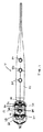
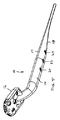
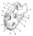
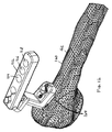
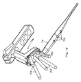
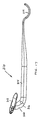
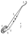
図1〜図6を参照すると、骨折部固定システムが提供されており、この骨折部固定システムは、釘プレート10を含んでおり、この釘プレート10は、プレート状頭部部分12、髄内釘部分14、および、これらのプレート状頭部部分12と髄内釘部分14との間に設けられた湾曲された首部分16を有し、この湾曲された首部分16は、頭部部分12と、釘部分14の上面17との間の角度αを規定している。角度αは、上腕骨160の骨幹162と、上腕骨近位部の骨幹端164の外側との間の角度に合わせるためには、約10°〜約25°であることが好ましい(図12および図24をも参照のこと)。
Referring to FIGS. 1-6, a fracture fixation system is provided, which includes a
釘部分14の上側の(解剖学的に外側の)面17は、髄管の骨内膜との接触のために実質的に直線になっており、下側の(解剖学的に内側の)面18は、上側の面に接近するように湾曲しているか、または角度をなして(angle)おり、釘部分の寸法が末端19に向かってしだいに細くなるようにしている。末端19は、髄管内への進入を容易にするために、実質的に一様で、より小さい直径をしている。釘部分14は、3つのコーティカルスクリュー用孔(cortical screw holes)20,22,24を含み、これらのコーティカルスクリュー用孔20,22,24には、好ましくは、機械ねじ山(machine threads)を備えたユニコーティカルスクリュー(unicortical screws)のねじ山付きシャフトを収容するための機械ねじ山が設けられていることが好ましい。図2および図25を参照すると、コーティカルスクリュー用孔20,22,24は、首部16から適当な距離Dだけ間隔をおいて配置されており、コーティカルスクリュー用孔20,22,24を介して挿入されるねじ190(図13から図15)が、肩峰の下約5cmのところを通る腋窩神経165と干渉することを防いでいる。好ましい距離Dは、接平面(tangent)Tから、骨折部の遠位側に据え付けられる首部16の内側湾曲部まで約3〜4cmであり、より好ましくは、約3.4cmである。
The upper (anatomically outer)
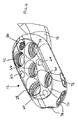
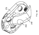
頭部部分12は、角度固定型固定ペグ46,48,50,52,54または固定ねじ(図13から図16)、すなわち、「骨支持要素」を収容するための固定用孔26,28,30,32,34を含む。固定用孔は、好ましくは、雌ねじ山を含むことによって「ロックする」ようになっている。好ましい実施形態では、5つの固定用孔が設けられており、中央固定用孔26は、上腕頭の関節面の中央に向かう軸線を規定し、そして、相対的に近位および遠位(ならびに、前方および後方)の固定用孔28,30,32,34は、軸線を有しており、これら軸線は、空間をあけて分配されており、中央固定用孔26の軸線および互いの軸線からそれているが、上腕頭内に多軸構造(multiaxial arrangement)を形成する。頭部部分12は、複数のKワイヤ位置合わせ用孔60,62,64をも含み、これらの孔は、Kワイヤを隙間なく収容し、骨支持要素の配置を予想するために、これらのワイヤの向きを定める。位置合わせ用孔62,64は、中央孔部26の前側および後側に配置されており、中央孔26の軸線に平行に延びる軸線を有する。位置合わせ用孔60,62,64およびKワイヤをこのようにして利用することが、2003年10月21日出願の米国特許出願第10/689,797号、2003年9月17日出願の同第10/664,371号、2004年11月10日出願の同第10/985,598号および2005年1月21日出願の同第11/040,724号に、より詳細に記載されており、これらの米国特許出願は、参照により本明細書にその全内容が組み込まれる。プレートは、ねじ付きジグ孔66をも含む。
The
頭部部分12の前部は、湾曲した縫合針によりアクセスすることのできるトンネル状の縫合用孔を含む。好ましい実施形態では、3つのトンネルが設けられている。すなわち、頭部部分の近位−遠位軸線A1に対して垂直であり、頭部部分12の中央平面Pを通って延びている第1中央トンネル70と、第1トンネル70の両側にあり、第1トンネルに対して約45°±15°の角度で位置している第2トンネル72および第3トンネル74とが設けられている。各トンネルは、好ましくは、頭部部分の厚さよりも長い側部を有する。3つの縫合用孔70,72,74の間に設けられた2つの溝76によって、または、頭部部分12の前端部に設けられた適当な構造によって、引っ掛け部(catch)が画定されている。溝76は、縫合針がトンネルに入ることをも可能にする。本発明によれば、プレートの外形に縫合用孔による明らかな不連続部がないように、頭部部分12の上側および前側の外形に扇形のスカラップ(scallops)や突起部はない。前端部が滑らかであることの利点は、頭部部分を横切って移動する組織に対して横方向の抵抗がないということである。
The front portion of the
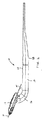
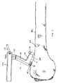
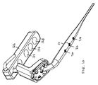
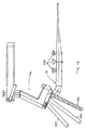
図7〜図12を参照すると、植え込み用ジグ100もまた提供されている。この植え込み用ジグ100は、装置10、特に頭部部分12に連結することができる。植え込み用ジグは、2つのインプラントアンカー104を備えた基部102と、ねじ山付きまたはねじ山の付いていないシャフト固定ペグ150(図13〜図16)を装置の頭部部分に挿入することのできるアクセス用開口106と、Kワイヤ位置合わせ用孔60,62,64と位置が揃っている位置合わせ用孔108,110,112と、連結用孔114とを含む。基部102は、アンカー104を引っ掛け部の溝部76に連結し、かつ、ねじ116を連結用孔114に通してジグ用孔66内へ固定することにより、プレートの頭部部分12に固定されている(図11も参照のこと)。台座118が基部102の前部から上方へ延びている。非円形の横断面を備えた少なくとも1つの部分を有するハンドル取り付け部120が台座118の上部に設けられており、釘部分14の上面18に対して垂直となる向きに向けられている(図9)。ハンドル122が取り外し可能なクランプ部123を介して非円形の取り付け部120に連結されている。クランプ部123は、ハンドルを、釘部分14のほぼ反対側の第1の位置に固定したり(図7および図8)、取り外して、少なくとも部分的に釘部分と重なる第2の位置に再配置(再構成)したりする(図9)ことを可能にする。図10および図12を参照すると、ハンドル122は案内用孔124,126,128を含み、これらの案内用孔は、ハンドルが第2の位置に位置する場合には、上腕骨160内の釘部分に設けられたコーティカルスクリュー用孔20,22,24の上に重なる。第1の位置は、装置の釘部分を操作して、内側に限局した空間(intrafocal space)を通して髄管内へ入れる際に、および、Kワイヤを位置合わせ用孔60,62,64に挿入し、固定ねじ150を植え込む際に、特に有用である。第2の位置は、より詳しく後述するように、コーティカルスクリューを釘部分に取り付ける際に用いられる。
With reference to FIGS. 7-12, an
ねじ案内用カニューレ170、ドリル案内用カニューレ180、および、栓子190が、植え込みジグ100とともに用いるために提供されている(図21〜図23を参照)。これらの3つのユニットは、組み合わされると、先に行くほど細くなる端部を形成し、この先に行くほど細くなる端部により、これら組み合わせたユニットを皮膚の小さな切開部に挿入し、組織を骨まで切断することが可能になる。この組立体は、孔124,126,128の1つに挿入され、骨まで導かれる。栓子180は、次に取り外され、ドリルがドリルガイド180に導入され、孔20,22,24の1つの上で骨皮質に孔をあけるのに用いられる。次にドリルおよびドリルガイドが引き抜かれ、機械ねじがカニューレ170に導入され、摩擦によってドライバに取り付けられる。一実施形態によれば、ねじ案内用カニューレ170は、近位開口(第1端部)と、遠位端部(第2端部)と、近位開口および遠位端部の間に長手方向に延びる中央部分とを有する。この中央部分は、遠位端のみを除く全体にわたって、ねじの頭にとって十分なようにわずかに大きい一定の内径を有する。ねじ案内用カニューレ170の遠位端では、直径がねじの頭部よりほんの少し小さくなっている。これは、例えば、(i)ねじ頭に対して若干干渉するように、(例えば機械加工により)この領域に小さな縁部を残す、または、(ii)例えばスリットの助けを借りてまたは借りずに、端部を、内側に折り曲げることにより、行うことができる。本発明によれば、ねじ頭と、ねじ案内用カニューレ170の端部にある小径部との間の干渉を克服するのに必要な力は、十分に小さく、これにより、ねじ頭をねじガイド170を介して骨の内部の装置の釘部分に設けられた孔内へ押し込むことができる。この特徴部の目的は、ねじがねじ案内用カニューレ170の中にある間にドライバから分離された場合に、ねじを保持し、外科医がこのねじを回収できるようにすることである。
A
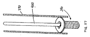
図26〜図28を参照すると、ねじの挿入を容易にするための別のねじ捕捉システムが提供されている。このシステムでは、標準的な直径が一定のガイド370(断面図で示されている)が使用される。ねじ390は頭部392を含み、この頭部392は、ドライバ406のための中央六角溝394と、この六角溝394の基部に設けられた(ねじのシャフトに設けられた機械ねじ山の行程とは反対の)逆方向ねじ山付き凹部396とを含む。連結ロッド400には、逆方向のねじ山404を有する端部402が設けられている。図27に示されているように、ロット400は、逆ねじ連結によってねじ390に物理的に結合されている。次にロッド400は、ねじ390をガイド370と、骨にあけられた孔とを介して、釘部分14のねじ孔20,22,24(図3)内へ導くために用いられる。ロッド400は、次に、ねじ390をねじ孔に挿入するために回転され、実質的に同時に、ロッドはねじ頭392から外され(unthread)、ねじから連結解除される。図28に示されているように、次に、ドライバ406は六角溝394に挿入され、駆動されて、ねじ孔内へのねじ390の挿入を完了する。当然のことながら、ねじ390とロッド400との間のねじ山結合部は、ねじ390とロッド400との間の解除を妨げるように、より大きい干渉性を有しているように設計することもできる。このような場合、ロッドを外す前に、ねじ390を実質的に完全に挿入するためにロッド400を使用することもでき、ドライバ406は、最終的なねじの締め付けに用いられる。もちろん、従来のあらゆるねじ駆動システム(screw driving system)を利用することもできる。
With reference to FIGS. 26-28, another screw capture system is provided to facilitate screw insertion. In this system, a standard constant diameter guide 370 (shown in cross section) is used. The
装置10の釘部分14に設けられた孔20,22,24と連結するために、ねじが正確にはどのようにねじ込まれたかにかかわらず、ねじを釘部分にねじ込むと、釘部分が皮質の骨内膜面に向けて引っ張られ、ねじの頭部が骨の外面に据え付けられる。この処理は、他の孔20,22,24について繰り返し行われ、これにより、機械ねじ山付きユニコーティカルスクリュー190,390が孔に挿入され、釘部分14が骨に対して締め付けられる。
Regardless of exactly how the screw is screwed in to connect with
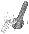
次に、図17〜図20に移ると、本発明による釘プレート210の第2実施形態が示されている。この釘プレート210は、釘プレート10と実質的に同様であるが、以下の相違点を含む。頭部部分212は、首部分216の上で相対的により後方に下げられており、中央固定用孔226が首部分を通って延び、頭部部分212の前端部と、肩峰(acromium)との間により大きな空きが設けられるようしてある。さらに、釘部分214の末端219には、下向きになり、次いで上向きになる湾曲部が設けられている。この湾曲部は、内側に限局された侵入(intrafocal entry)のために釘部分の末端の措置を容易にする。
Turning now to FIGS. 17-20, a second embodiment of a
次に図21〜図23を参照すると、釘プレート210が植え込み用ジグ100に連結されているところが示されている。この植え込み用ジグ100は、変更を施すことなく、釘プレート10および210の両方で使用できる。ねじ案内用カニューレ170およびドリルガイド180が、装置210の釘部分214に設けられたねじ孔222の上に配置されたハンドル122の孔126に入っているところが示されている。
Referring now to FIGS. 21-23, the
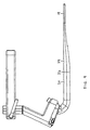
図24を参照すると、本発明によれば、上腕骨160の大きさに拘わらず、すなわち、骨の頭部が166aで示されているように比較的小さくても、166bで示されているように比較的大きくても、単一サイズのインプラントを使用することができ、インプラントの位置が解剖学的に適切に合うことは、(i)釘部分214を骨幹162の軸線A2に平行に伸ばすこと、および、(ii)中央固定用ペグ(または固定用ねじ)150aを上腕頭の関節面の中央168a,168bに向けて延ばすことにより保証できる。幾何学的には、軸線Aと、関節面の中央に垂直な線との間の角度が、一般に45°±20°であり、より一般的には45°プラスマイナス10°である。位置合わせ用孔262,264(図18)に挿入されたKワイヤ(不図示)により、中央孔226の位置が正確に合わせられたことが、固定用ペグのための孔をあけ、その孔に固定用ペグを挿入する前に確認できる。中央孔が正確に位置合わせされると、残りの孔およびペグが適切に空間をあけて(spatially)分配されることが保証される。
Referring to FIG. 24, according to the present invention, regardless of the size of the
より具体的に、釘プレート10(または、210)、ジグ100およびカニューレ170を使用する方法を、以下に簡単に説明する。骨折部上で、骨までの小さな切開部を設ける。次に、骨の小片を骨折部の遠位(骨幹)側で(例えば、骨鉗子を用いて)除去し、釘プレート10の首部分16を収容するための空間を画定する。骨折部を整復する。ハンドル122を首部分14とほぼ反対側の第1の位置に固定した状態で、ジグ100を釘プレートに連結する。次に、釘部分14の小さい端部19が、図7および図8に示されているように首部分16が骨内の画定された空間内に据えられ、頭部部分12が骨幹端(metaphysis)の上に比較的ぴったりと接した状態で(flat)支持されるまで、切開部に通され、内側に限局されるよう(intrafocally)に髄管内へ導かれる。選択的には、釘プレートは、ジグに取り付けずに、手作業で髄管内に、そして骨幹端上に導入し、ジグは後から取り付けられる。
More specifically, a method of using the nail plate 10 (or 210), the
次に、好ましくは、一本以上のKワイヤが、上腕骨近位部の頭部に突き通され、骨幹端上で頭部の位置が合っていることを保証するために、X線透視検査で観察される。位置が正確に合っていることをKワイヤが示したと想定すると、固定用ペグまたは固定ねじを収容するために、固定用孔を介して骨幹端に孔があけられる。Kワイヤが、望まれるよりも位置が合っていないことを示した場合、プレートと上腕頭とは、相対的に再び位置を合わせられ、Kワイヤが再び挿入され、位置が合っているか再評価がなされ、位置合わせが満足すべきものであれば、孔があけられる。固定用ペグまたは固定ねじは、あけられた孔に挿入され、上腕頭を釘プレートの頭部部分12に対して安定させるようにプレート10に対して固定される。
Next, preferably one or more K-wires are pierced through the head of the proximal humerus to ensure that the head is aligned on the metaphysis. Observed at. Assuming that the K-wire indicates that it is correctly aligned, a hole is drilled in the metaphysis through the fixation hole to accommodate the fixation peg or fixation screw. If the K-wire indicates that it is not aligned more than desired, the plate and humeral head will be re-aligned relatively and the K-wire will be re-inserted and re-evaluated for alignment. If the alignment is satisfactory, a hole is drilled. A fixing peg or fixing screw is inserted into the drilled hole and fixed to the
次にジグ100のハンドル122の向きが逆にされ(または取り付けられて)、釘部分14(図10)の上に重ねられ、かつ、上腕の組織および皮膚の上に配置される。各案内用孔122,124,126のために、ねじ案内用カニューレ170、ドリル案内用カニューレ180および栓子190が一緒に挿入され、栓子190は皮膚を破り、組織を通って骨幹骨までの通り道を規定する。次に、栓子190は引き抜かれ、ドリルがドリルガイド180に導入され、孔20,22,24の1つの上で骨皮質に孔をあける。ドリルおよびドリルガイドは、その後引き抜かれ、ドライバに取り付けられた機械ねじが、カニューレ170を介して導入され、ねじのシャフトがそれぞれの孔20,22,24にねじ込まれ、これにより釘部分14が骨の骨内膜面に引きつけられる。この処理は、釘部分にある残りの孔部20,22,24について繰り返される。ジグ100がその後釘プレート10から取り除かれ、切開部が閉じられる。
The
当然のことながら、この方法のさまざまなステップは、この釘プレートおよびこの手技によって与えられる低侵襲の性質、効率、および固定に影響を与えることなく順番を入れ替えることができる。 Of course, the various steps of the method can be reordered without affecting the minimally invasive nature, efficiency, and fixation afforded by the nail plate and the procedure.
骨折部固定システム、ジグ、ならびに、そのジグの使用方法およびそのシステムの植え込み方法のいくつかの実施形態を説明し、図示した。本発明の特定の実施形態を説明したが、本発明をそれに限定しようとするものではない。これは、本発明の範囲は、その技術が許す限り広く、本明細書は、そのように読まれることが意図されているからである。よって、固定装置は、上腕骨の骨折整復について説明したが、示した構造または本発明の観点と同様の構造は、他の骨に用いることができ、特に長骨に用いることができることは分かるであろう。したがって、当業者には分かるであろうが、特許請求の範囲の趣旨および範囲から逸脱することなく、本発明にさらに別の変更を行うことができる。 Several embodiments of a fracture fixation system, a jig, and methods of using the jig and implanting the system have been described and illustrated. While specific embodiments of the invention have been described, it is not intended that the invention be limited thereto. This is because the scope of the present invention is as broad as the technology allows, and the specification is intended to be read as such. Thus, although the fixation device has been described for fracture reduction of the humerus, it will be appreciated that the structure shown or similar to the aspects of the present invention can be used for other bones, especially for long bones. I will. Accordingly, those skilled in the art will recognize that further modifications can be made to the present invention without departing from the spirit and scope of the appended claims.
〔実施の態様〕
(1)骨の骨折部を固定するためのインプラントであって、前記骨が、髄管を備えた骨幹、髄管内の骨内膜、および、端部に関節面を備えた骨幹端を有する、インプラントにおいて、
a)髄内釘部分であって、実質的に真っ直ぐな骨内膜面、および、前記釘部分に沿って互いに長手方向に位置をずらして配置された複数のねじ山付きねじ孔、を有する、髄内釘部分と、
b)前記骨内膜面に対して所定の角度をなすプレート状頭部部分であって、前記頭部部分は、複数の固定用孔を含み、これらの固定用孔では、骨支持要素を前記頭部部分に対して固定することができる、プレート状頭部部分と、
c)前記頭部部分および前記釘部分の間に設けられた首部分と、
を備える、インプラント。
(2)実施態様1に記載のインプラントにおいて、
前記頭部部分と前記首部分との間の角度が、約10°〜約25°である、インプラント。
(3)実施態様1に記載のインプラントにおいて、
前記釘部分は、前記骨内膜面の実質的に反対側の面を有し、この面は、前記釘部分の寸法が末端部に向かってしだいに細くなるように、前記骨内膜面に接近する、インプラント。
(4)実施態様3に記載のインプラントにおいて、
前記末端部には、湾曲部が設けられている、インプラント。
Embodiment
(1) An implant for fixing a fracture portion of a bone, wherein the bone has a diaphysis having a medullary canal, an intraosseous intima in the medullary canal, and a metaphysis having an articular surface at an end thereof. In the implant
a) an intramedullary nail portion having a substantially straight endosteal surface and a plurality of threaded screw holes disposed longitudinally offset from each other along the nail portion; An intramedullary nail portion;
b) a plate-shaped head portion having a predetermined angle with respect to the endosteal surface, the head portion including a plurality of fixing holes, wherein the bone supporting elements are arranged in the fixing holes; A plate-shaped head portion that can be fixed to the head portion;
c) a neck portion provided between the head portion and the nail portion;
An implant.
(2) In the implant according to embodiment 1,
The implant wherein the angle between the head portion and the neck portion is about 10 ° to about 25 °.
(3) In the implant according to embodiment 1,
The nail portion has a surface that is substantially opposite the endosteal surface, and this surface is located on the endosteal surface such that the dimension of the nail portion gradually decreases toward the distal end. Approach the implant.
(4) In the implant according to
The implant, wherein the distal end portion is provided with a curved portion.
(5)実施態様1に記載のインプラントにおいて、
前記頭部部分は、5つの固定用孔を含み、前記固定用孔の各々は、それぞれ別個の軸線を規定しており、前記固定用孔の1つが、中央固定用孔であり、
前記頭部部分が前記骨幹端に据え付けられると、前記中央固定用孔が、前記骨の関節面の中央に向かって方向付けられた軸線を規定する、インプラント。
(6)実施態様5に記載のインプラントにおいて、
前記固定用孔の残りが、空間をあけて分配されていて、かつ前記中央固定用孔の前記軸線からそれている、軸線を有する、インプラント。
(7)実施態様5に記載のインプラントにおいて、
前記中央固定用孔は、前記首部分を通って延びている、インプラント。
(8)実施態様1に記載のインプラントにおいて、
前記頭部部分は、少なくとも1つのKワイヤ位置合わせ用孔を含み、前記Kワイヤ位置合わせ用孔は、Kワイヤを所定の角度で安定して収容するような大きさに形成されている、インプラント。
(9)実施態様1に記載のインプラントにおいて、
前記頭部部分は、少なくとも1つのねじ山の付いていない縫合用孔を含み、前記ねじ山の付いていない縫合用孔では、縫合糸を前記頭部部分に連結することができる、インプラント。
(5) In the implant according to embodiment 1,
The head portion includes five fixing holes, each of the fixing holes defining a separate axis, and one of the fixing holes is a central fixing hole,
An implant wherein, when the head portion is installed at the metaphysis, the central fixation hole defines an axis directed toward the center of the articular surface of the bone.
(6) In the implant according to embodiment 5,
An implant having an axis, the remainder of the fixation hole being distributed in space and deviating from the axis of the central fixation hole.
(7) In the implant according to embodiment 5,
The central fixation hole extends through the neck portion.
(8) In the implant according to embodiment 1,
The head portion includes at least one K-wire alignment hole, and the K-wire alignment hole is sized to stably receive the K-wire at a predetermined angle. .
(9) In the implant according to embodiment 1,
An implant wherein the head portion includes at least one unthreaded suture hole in which a suture can be coupled to the head portion.
(10)実施態様9に記載のインプラントにおいて、
前記頭部部分は、厚さを有し、
前記少なくとも1つの縫合用孔は、3つの縫合用トンネルを含み、前記縫合用トンネルの各々は、前記頭部部分の前記厚さよりも長い側部を含む、インプラント。
(11)実施態様9に記載のインプラントにおいて、
前記頭部部分は、近位−遠位軸線および中央平面を有し、
前記少なくとも1つの縫合用孔は、
3つの縫合用トンネルであって、
前記近位−遠位軸線に対して垂直であり、前記中央平面を通って延びる、第1の中央トンネル、および、
前記第1のトンネルの両側に設けられており、前記第1のトンネルに対して約45°±15°の角度で位置している、第2および第3のトンネル、
を含む、3つの縫合用トンネル、
を含む、インプラント。
(12)実施態様1に記載のインプラントにおいて、
前記頭部部分は、植え込み用ジグを前記頭部部分に連結するための引っ掛け部を含む、インプラント。
(13)実施態様12に記載のインプラントにおいて、
前記引っ掛け部は、前記釘部分とは反対側の前記頭部部分の端部に位置しており、
前記頭部部分は、植え込み用ジグを、前記引っ掛け部とは反対側の前記頭部部分の端部に固定するためのねじ孔をさらに含む、インプラント。
(14)実施態様1に記載のインプラントにおいて、
前記インプラントは、上腕骨近位部に植え込むための大きさに形成されている、インプラント。
(10) In the implant according to embodiment 9,
The head portion has a thickness;
The at least one suturing hole includes three suturing tunnels, each of the suturing tunnels including a side of the head portion that is longer than the thickness.
(11) In the implant according to embodiment 9,
The head portion has a proximal-distal axis and a central plane;
The at least one suture hole comprises:
Three suture tunnels,
A first central tunnel perpendicular to the proximal-distal axis and extending through the central plane; and
Second and third tunnels provided on both sides of the first tunnel and located at an angle of about 45 ° ± 15 ° with respect to the first tunnel;
3 suture tunnels, including
Including an implant.
(12) In the implant according to embodiment 1,
The head portion includes an anchor for connecting an implantable jig to the head portion.
(13) In the implant according to
The hook is located at the end of the head portion opposite the nail portion;
The head portion further includes a screw hole for fixing the implantation jig to an end portion of the head portion opposite to the hook portion.
(14) In the implant according to embodiment 1,
The implant is sized for implantation in a proximal humerus.
(15)整形外科用インプラントと共に使用するための植え込み用ジグであって、前記インプラントは、角度固定型骨支持要素を連結することができるプレート状頭部部分、および髄内釘部分を有する、植え込み用ジグにおいて、
a)基部と、
b)前記基部をインプラントに連結するための手段と、
c)前記基部の一端から上方へ延びる台座と、
d)前記台座の上部に設けられたハンドル取り付け部と、
e)ハンドルであって、前記ハンドルが、前記釘部分とはほぼ反対側の第1の位置に回転可能に固定されることを可能にするか、または、再構成されて、前記釘部分の上に少なくとも部分的に重なる第2の位置に回転可能に固定されることを可能にするように、前記ハンドル取り付け部に連結されている、ハンドルと、
を備える、植え込み用ジグ。
(16)実施態様15に記載の植え込み用ジグにおいて、
前記基部は、アクセス用開口を含み、前記骨支持要素を、前記アクセス用開口を介して前記インプラントの前記プレート部分に挿入できる、植え込み用ジグ。
(17)実施態様15に記載の植え込み用ジグにおいて、
前記ハンドルは、案内用孔を含み、前記案内用孔は、前記ジグが前記インプラントに連結され、前記ハンドルが前記第2の位置にあるときに、前記釘部分に設けられたねじ孔の上に重なる、植え込み用ジグ。
(15) An implantable jig for use with an orthopedic implant, the implant having a plate-like head portion to which a fixed angle bone support element can be coupled, and an intramedullary nail portion For jigs,
a) a base;
b) means for connecting the base to the implant;
c) a pedestal extending upward from one end of the base;
d) a handle mounting portion provided at the top of the pedestal;
e) a handle that allows the handle to be rotationally secured in a first position substantially opposite the nail portion or is reconfigured to be above the nail portion; A handle coupled to the handle attachment portion to enable rotation to be secured to a second position at least partially overlapping the handle;
A jig for implantation.
(16) In the implantation jig according to
An implantable jig, wherein the base includes an access opening and the bone support element can be inserted into the plate portion of the implant through the access opening.
(17) In the implantation jig according to
The handle includes a guide hole, the guide hole being over the screw hole provided in the nail portion when the jig is coupled to the implant and the handle is in the second position. Overlapping jigs for implantation.
(18)実施態様15に記載の植え込み用ジグにおいて、
前記ハンドル取り付け部は、非円形の横断面を備えた部分を有し、
前記ハンドルは、非円形開口を有し、前記非円形開口では、前記ハンドルが、前記取り付け部の前記非円形の横断面を供えた部分に連結される、植え込み用ジグ。
(19)実施態様15に記載の植え込み用ジグにおいて、
前記ハンドルは、外すことができるクランプを介して前記ハンドル取り付け部に連結されている、植え込み用ジグ。
(20)実施態様15に記載の植え込み用ジグにおいて、
前記連結するための手段は、前記インプラントに機械的に連結するように構成された少なくとも1つのインプラントアンカーを含む、植え込み用ジグ。
(21)実施態様15に記載の植え込み用ジグにおいて、
前記連結するための手段は、ねじ山付き孔および固定用ねじを含む、植え込み用ジグ。
(18) In the implantation jig according to
The handle attachment portion has a portion with a non-circular cross-section,
An implantable jig wherein the handle has a non-circular opening, wherein the handle is connected to a portion of the mounting portion that provides the non-circular cross-section.
(19) In the implantation jig according to
An implantable jig, wherein the handle is connected to the handle attachment via a detachable clamp.
(20) In the implantation jig according to
An implantable jig, wherein the means for coupling includes at least one implant anchor configured to mechanically couple to the implant.
(21) In the implantation jig according to
The implanting jig, wherein the means for connecting includes a threaded hole and a locking screw.
(22)整形外科用インプラント、および、骨折した骨への前記インプラントの植え込みを容易にする植え込み用ジグ、を含むシステムにおいて、
a)前記インプラントは、
髄内釘部分であって、
実質的に真っ直ぐな骨内膜面、および、
前記釘部分に沿って長手方向に互いにずらして配置された複数のねじ孔、
を有する、髄内釘部分と、
プレート状頭部部分であって、
前記釘部分のほぼ反対側に位置する第1の端部、および、
前記釘部分のより近くに位置する第2の端部、
を含み、
前記第1の端部は、少なくとも1つの引っ掛け部を含む、
プレート状頭部部分と、
を含み、
b)前記植え込み用ジグは、
i)前記引っ掛け部と連結するように構成された少なくとも1つのアンカーを有する基部と、
ii)前記基部を前記インプラントの前記プレート部分の前記第2の端部に連結するための連結手段と、
iii)前記基部の一端から上方へ延びる台座と、
iv)前記台座の上部に設けられたハンドル取り付け部と、
v)ハンドルであって、前記ハンドルが、前記釘部分とはほぼ反対側の第1の位置に固定されることを可能にし、および、前記釘部分の上に少なくとも部分的に重なる第2の位置になるよう再構成されることを可能にするように、前記ハンドル取り付け部に連結されている、ハンドルと、
を含む、
システム。
(22) In a system comprising an orthopedic implant and an implantation jig that facilitates implantation of the implant into a fractured bone,
a) The implant is
An intramedullary nail part,
A substantially straight endosteal surface, and
A plurality of screw holes arranged to be shifted from each other in the longitudinal direction along the nail portion;
Having an intramedullary nail portion;
A plate-shaped head part,
A first end located generally opposite the nail portion; and
A second end located closer to the nail portion;
Including
The first end includes at least one hook;
A plate-shaped head part;
Including
b) The implantation jig is
i) a base having at least one anchor configured to couple with the hook;
ii) connecting means for connecting the base to the second end of the plate portion of the implant;
iii) a pedestal extending upward from one end of the base;
iv) a handle mounting portion provided on the top of the pedestal;
v) a handle, wherein the handle allows the handle to be secured in a first position substantially opposite the nail portion, and a second position at least partially overlying the nail portion A handle coupled to the handle mount to allow reconfiguration to
including,
system.
(23)実施態様22に記載のシステムにおいて、
前記手段は、
前記プレート部分に設けられたねじ山付き孔と、
固定用ねじと、
を含む、システム。
(24)実施態様22に記載のシステムにおいて、
前記ハンドルは、外すことができるクランプを介して前記ハンドル取り付け部に連結されている、システム。
(25)第1の直径を備えた頭部を有するねじと共に使用するためのねじ案内用カニューレにおいて、
カニューレであって、
第1および第2の端部と、
前記第1および第2の端部の間に長手方向に延びる中央部分と、
を有し、
前記中央部分は、前記ねじの前記頭部が前記中央部分を通るのに十分に大きい第2の内径を有し、
前記第2の端部は、より小さい第3の内径を有し、前記第3の内径は、前記ねじの頭部を前記第2の端部に押し通すことができるが、前記ねじが前記カニューレ内で緩くなると、前記ねじが前記第2の端部によって保持されるように、十分に大きい、
カニューレ、
を備える、ねじ案内用カニューレ。
(26)実施態様25に記載のねじ案内用カニューレにおいて、
前記第2の内径は、一定である、ねじ案内用カニューレ。
(27)実施態様25に記載のねじ案内用カニューレにおいて、
前記第1の直径および前記第2の内径は、ほぼ同じである、ねじ案内用カニューレ。
(23) In the system according to
The means is
A threaded hole provided in the plate portion;
Fixing screws;
Including the system.
(24) In the system according to
The system, wherein the handle is connected to the handle attachment via a removable clamp.
(25) In a screw guide cannula for use with a screw having a head with a first diameter,
A cannula,
First and second ends;
A central portion extending longitudinally between the first and second ends;
Have
The central portion has a second inner diameter large enough for the head of the screw to pass through the central portion;
The second end has a smaller third inner diameter, the third inner diameter can push the head of the screw through the second end, but the screw is within the cannula. The screw is sufficiently large so that the screw is held by the second end,
Cannula,
A screw guide cannula.
(26) In the screw guiding cannula according to embodiment 25,
The screw guide cannula, wherein the second inner diameter is constant.
(27) The screw guide cannula according to embodiment 25,
The screw guide cannula, wherein the first diameter and the second inner diameter are substantially the same.
(28)実施態様25に記載のねじ案内用カニューレにおいて、
前記第3の内径は、前記第2の端部を機械加工することによって規定される、ねじ案内用カニューレ。
(29)実施態様25に記載のねじ案内用カニューレにおいて、
前記第3の直径は、前記第2の端部に設けられた内側の縁部によって規定される、ねじ案内用カニューレ。
(30)実施態様25に記載のねじ案内用カニューレにおいて、
前記第3の直径は、前記第2の端部を内側に曲げることによって規定される、ねじ案内用カニューレ。
(31)実施態様30に記載のねじ案内用カニューレにおいて、
前記第2の端部は、内側に曲げられたスリット部を含む、ねじ案内用カニューレ。
(32)骨ネジにおいて、
a)回転駆動用溝を有する頭部であって、
前記溝部は、下面、および、前記下面に設けられたねじ山付き凹部を有し、
前記ねじ山付き凹部は、第1の方向に延びるねじ山を有する、
頭部と、
b)前記第1の方向と反対の第2の方向に延びるねじ山を有するシャフトと、
を備える、骨ネジ。
(28) The screw guide cannula according to embodiment 25,
The screw guide cannula, wherein the third inner diameter is defined by machining the second end.
(29) The screw guide cannula according to embodiment 25,
The screw guide cannula, wherein the third diameter is defined by an inner edge provided at the second end.
(30) The screw guiding cannula according to embodiment 25,
The screw guide cannula, wherein the third diameter is defined by bending the second end inward.
(31) The screw guide cannula according to
The second end portion is a screw guide cannula including a slit portion bent inwardly.
(32) In the bone screw,
a) a head having a groove for rotational driving,
The groove has a lower surface and a threaded recess provided on the lower surface,
The threaded recess has a thread extending in a first direction;
The head,
b) a shaft having a thread extending in a second direction opposite to the first direction;
With bone screws.
(33)実施態様32に記載の骨ネジにおいて、
前記シャフトに設けられた前記ねじ山は、機械ねじ山である、骨ネジ。
(34)実施態様32に記載の骨ネジにおいて、
前記回転駆動用溝は、六角溝である、骨ネジ。
(35)組み合わせにおいて、
前記組み合わせは、実施態様32に記載の骨ネジと、ロッドと組み合わせであり、
前記ロッドは、前記第1の方向に延びるねじ山を備えた端部を有し、
前記端部は、前記ねじの前記頭部に設けられた前記ねじ山付き凹部に、ねじ山により連結される、組み合わせ。
(36)実施態様35に記載の組み合わせにおいて、
骨折部固定用インプラントと組み合わされており、
前記インプラントは、前記ねじの前記シャフトを収容するための少なくとも1つのねじ山付き孔を含み、
前記ロットと前記ねじ山付き凹部との間のねじ山連結部の連結解除が、前記シャフトを前記ねじ山付き孔に挿入するよりも大きい力を必要とする、組み合わせ。
(33) In the bone screw according to
The screw provided on the shaft is a bone screw, which is a mechanical screw thread.
(34) In the bone screw according to
The rotation drive groove is a bone screw, which is a hexagonal groove.
(35) In combination:
The combination is a combination of a bone screw according to
The rod has an end with a thread extending in the first direction;
The combination wherein the end is connected by a thread to the threaded recess provided at the head of the screw.
(36) In the combination according to embodiment 35,
Combined with a fracture fixation implant,
The implant includes at least one threaded hole for receiving the shaft of the screw;
A combination wherein uncoupling of the threaded connection between the lot and the threaded recess requires a greater force than inserting the shaft into the threaded hole.
(37)関節面を含む骨幹端を有する骨折した骨に釘プレートインプラントを植え込む方法であって、前記インプラントが、ねじ孔を備えた釘部分、固定用孔を備えたプレート部分、および、前記釘部分と前記プレート部分との間に設けられた首部分を有する、方法において、
a)前記骨折部の一方側で骨の一部を除去する段階と、
b)前記骨折部を整復する段階と、
c)前記首部分が前記骨折部の前記一方側に画定された空間内に据え付けられ、かつ前記頭部部分が前記骨幹端に支持されるまで、前記釘プレートインプラントの前記釘部分を、内側に限局されるように髄管の中へ挿入する段階と、
d)骨支持要素を前記骨幹端に挿入し、前記骨支持要素を前記プレート部分に対して固定する段階と、
e)ジグを前記インプラントに連結する段階であって、前記ジグは、案内用孔を備えたハンドルを含んでいる、段階と、
f)前記ジグの前記ハンドルを前記釘部分の上に重なるように配置する段階と、
g)前記案内用孔を介して、前記骨、および前記釘部分に設けられた前記ねじ孔に、孔をあける段階と、
h)ドライバを用いて、ねじを、ねじ案内用カニューレに通し、あけられた前記孔および前記釘部分に設けられた前記ねじ孔に挿入する段階であって、前記ねじ案内用カニューレは、前記カニューレ内でねじが前記ドライバから離されるのが早すぎた場合に、前記ねじを前記カニューレ内で保持する、段階と、
を含む、方法。
(37) A method of implanting a nail plate implant into a fractured bone having a metaphysis including an articular surface, wherein the implant includes a nail portion having a screw hole, a plate portion having a fixing hole, and the nail. Having a neck portion provided between the portion and the plate portion,
a) removing a portion of the bone on one side of the fracture;
b) reducing the fracture,
c) the nail portion of the nail plate implant inward until the neck portion is installed in a space defined on the one side of the fracture and the head portion is supported by the metaphysis. Inserting into the medullary canal to be confined;
d) inserting a bone support element into the metaphysis and securing the bone support element to the plate portion;
e) connecting a jig to the implant, the jig including a handle with a guide hole;
f) placing the handle of the jig overlying the nail portion;
g) drilling the bone and the screw hole provided in the nail portion through the guide hole;
h) using a screwdriver to pass a screw through the screw guide cannula and into the drilled hole and the screw hole provided in the nail portion, the screw guide cannula being inserted into the cannula; Holding the screw within the cannula if the screw is released too early from the driver;
Including a method.
(38)実施態様37に記載の方法において、
前記骨は、前記骨折部の遠位側から除去される、方法。
(39)実施態様37に記載の方法において、
前記ジグは、前記釘部分を前記髄管に挿入する前に前記インプラントに連結される、方法。
(40)実施態様37に記載の方法において、
前記釘部分を挿入する前に、前記ハンドルが前記釘部分とほぼ反対側に方向付けされた位置に固定された状態で、前記ジグを前記釘プレートに連結する段階、
をさらに含む、方法。
(41)実施態様37に記載の方法において、
前記骨支持要素を挿入する前に、少なくとも1つのKワイヤが、前記固定用孔を通して前記プレート部分および前記骨幹端に突き通され、また、前記骨幹端上で前記頭部部分の位置が合っているかを観察するために、X線透視検査で検査される、方法。
(38) In the method of embodiment 37,
The method wherein the bone is removed from a distal side of the fracture.
(39) In the method of embodiment 37,
The jig is coupled to the implant prior to inserting the nail portion into the medullary canal.
(40) In the method of embodiment 37,
Connecting the jig to the nail plate with the handle secured in a position oriented generally opposite the nail portion prior to inserting the nail portion;
Further comprising a method.
(41) In the method of embodiment 37,
Prior to inserting the bone support element, at least one K-wire is pierced through the fixation hole into the plate portion and the metaphysis, and the head portion is aligned on the metaphysis. A method that is examined by fluoroscopy to observe whether or not.
(42)関節面を含む骨幹端を有する骨折した骨に釘プレートインプラントを植え込む方法であって、前記インプラントが、ねじ孔を備えた釘部分、固定用孔を備えたプレート部分、および、前記釘部分と前記プレート部分との間に設けられた首部分を有する、方法において、
a)前記骨折部の一方側で骨の一部を除去する段階と、
b)骨折部を整復する段階と、
c)前記ハンドルが前記釘部分とほぼ反対側に方向付けられた位置で固定された状態で、前記ジグを前記釘プレートに連結する段階と、
d)前記首部が前記骨折部の前記一方側に画定された空間内に据え付けられ、前記頭部部分が前記骨幹端に支持されるまで、前記釘プレートインプラントの前記釘部分を、内側に限局されるように髄管の中へ挿入する段階と、
e)骨支持要素を前記骨幹端に挿入し、前記骨支持要素を前記プレート部分に対して固定する段階と、
f)前記釘部分の上に重なるように前記ジグの前記ハンドルを再配置する段階と、
g)前記案内用孔部を介して、前記骨、および前記釘部分に設けられた前記ねじ孔に、孔をあける段階と、
h)あけられた前記孔、および前記釘部分に設けられた前記ねじ孔に、ねじを挿入する段階と、
を含む、方法。
(42) A method for implanting a nail plate implant into a fractured bone having a metaphysis including an articular surface, wherein the implant includes a nail portion having a screw hole, a plate portion having a fixing hole, and the nail. Having a neck portion provided between the portion and the plate portion,
a) removing a portion of the bone on one side of the fracture;
b) reducing the fracture,
c) coupling the jig to the nail plate with the handle secured in a position oriented generally opposite the nail portion;
d) The nail portion of the nail plate implant is confined inward until the neck is installed in a space defined on the one side of the fracture and the head portion is supported by the metaphysis. Inserting it into the medullary canal,
e) inserting a bone support element into the metaphysis and securing the bone support element to the plate portion;
f) repositioning the handle of the jig overlying the nail portion;
g) drilling a hole in the screw hole provided in the bone and the nail portion through the guide hole;
h) inserting a screw into the drilled hole and the screw hole provided in the nail portion;
Including a method.
(43)実施態様42に記載の方法において、
前記骨が、前記骨折部の遠位側から除去される、方法。
(44)実施態様42に記載の方法において、
前記骨支持要素を挿入する前に、少なくとも1つのKワイヤが、前記固定用孔を通して前記プレート部分および前記骨幹端に突き通され、また、前記骨幹端の上で前記頭部部分の位置が合っているかを観察するために、X線透過検査で検査される、方法。
(45)釘部分、プレート部分、および、前記釘部分と前記プレート部との間に設けられた首部分を有する釘プレートインプラントを骨折した上腕骨近位部に植え込む方法において、
a)骨の一部を骨折部の一方側で除去する段階と、
b)骨折部を整復する段階と、
c)前記首部が前記骨折部の前記一方側に画定された空間内に据え付けられ、前記頭部部分が前記上腕骨近位部の骨幹端に支持されるまで、前記釘プレートインプラントの前記釘部分を内側に限局されるように髄管の中へ挿入する段階と、
を含む、方法。
(46)実施態様45に記載の方法において、
前記骨は、前記骨折部の遠位側で除去される、方法。
(43) In the method of embodiment 42,
The method wherein the bone is removed from the distal side of the fracture.
(44) In the method of embodiment 42,
Prior to inserting the bone support element, at least one K-wire is pierced through the fixation hole into the plate portion and the metaphysis, and the head portion is aligned over the metaphysis. A method that is inspected by X-ray transmission to see if it is.
(45) In a method of implanting a nail plate implant having a nail portion, a plate portion, and a neck portion provided between the nail portion and the plate portion into a fractured proximal portion of the humerus,
a) removing a portion of the bone on one side of the fracture;
b) reducing the fracture,
c) The nail portion of the nail plate implant until the neck is seated in a space defined on the one side of the fracture and the head portion is supported on the metaphysis of the proximal humerus Inserting it into the medullary canal so that it is confined to the inside,
Including a method.
(46) In the method according to embodiment 45,
The method wherein the bone is removed distal to the fracture.
Claims (14)
a)髄内釘部分であって、実質的に真っ直ぐな骨内膜面、および、前記釘部分に沿って互いに長手方向に位置をずらして配置された複数のねじ山付きねじ孔、を有する、髄内釘部分と、
b)前記骨内膜面に対して所定の角度をなすプレート状頭部部分であって、前記頭部部分は、複数の固定用孔を含み、これらの固定用孔では、骨支持要素を前記頭部部分に対して固定することができ、前記固定用孔の1つが中央固定用孔である、プレート状頭部部分と、
c)前記頭部部分および前記釘部分の間に設けられた首部分であって、前記中央固定用孔が前期首部分を通って延びている、首部分と、
を備える、インプラント。 An implant for fixing a bone fracture, wherein the bone has a diaphysis with a medullary canal, an endosteal in the medullary canal, and a metaphysis with an articular surface at the end,
a) an intramedullary nail portion having a substantially straight endosteal surface and a plurality of threaded screw holes disposed longitudinally offset from each other along the nail portion; An intramedullary nail portion;
b) a plate-shaped head portion having a predetermined angle with respect to the endosteal surface, the head portion including a plurality of fixing holes, wherein the bone supporting elements are arranged in the fixing holes; A plate-shaped head portion that can be fixed to the head portion, wherein one of the fixing holes is a central fixing hole;
c) a neck portion provided between the head portion and the nail portion, wherein the central fixing hole extends through the neck portion;
An implant.
前記頭部部分と前記釘部分との間の角度が、10°〜25°である、インプラント。 The implant of claim 1, wherein
An implant wherein the angle between the head portion and the nail portion is between 10 ° and 25 ° .
前記釘部分は、前記骨内膜面の実質的に反対側の面を有し、この面は、前記釘部分の寸法が末端部に向かってしだいに細くなるように、前記骨内膜面に接近する、インプラント。 The implant of claim 1, wherein
The nail portion has a surface that is substantially opposite the endosteal surface, and this surface is located on the endosteal surface such that the dimension of the nail portion gradually decreases toward the distal end. Approach the implant.
前記末端部には、湾曲部が設けられている、インプラント。 The implant according to claim 3,
The implant, wherein the distal end portion is provided with a curved portion.
前記頭部部分は、5つの固定用孔を含み、前記固定用孔の各々は、それぞれ別個の軸線を規定しており、前記固定用孔の1つが、中央固定用孔であり、
前記頭部部分が前記骨幹端に据え付けられると、前記中央固定用孔が、前記骨の関節面の中央に向かって方向付けられた軸線を規定する、インプラント。 The implant of claim 1, wherein
The head portion includes five fixing holes, each of the fixing holes defining a separate axis, and one of the fixing holes is a central fixing hole,
An implant wherein, when the head portion is installed at the metaphysis, the central fixation hole defines an axis directed toward the center of the articular surface of the bone.
前記固定用孔の残りが、空間をあけて分配されていて、かつ前記中央固定用孔の前記軸線からそれている、軸線を有する、インプラント。 The implant according to claim 5,
An implant having an axis, the remainder of the fixation hole being distributed in space and deviating from the axis of the central fixation hole.
前記中央固定用孔は、前記首部分を通って延びている、インプラント。 The implant according to claim 5,
The central fixation hole extends through the neck portion.
前記頭部部分は、少なくとも1つのKワイヤ位置合わせ用孔を含み、前記Kワイヤ位置合わせ用孔は、Kワイヤを所定の角度で安定して収容するような大きさに形成されている、インプラント。 The implant of claim 1, wherein
The head portion includes at least one K-wire alignment hole, and the K-wire alignment hole is sized to stably receive the K-wire at a predetermined angle. .
前記頭部部分は、少なくとも1つのねじ山の付いていない縫合用孔を含み、前記ねじ山の付いていない縫合用孔では、縫合糸を前記頭部部分に連結することができる、インプラント。 The implant of claim 1, wherein
An implant wherein the head portion includes at least one unthreaded suture hole in which a suture can be coupled to the head portion.
前記頭部部分は、厚さを有し、
前記少なくとも1つの縫合用孔は、3つの縫合用トンネルを含み、前記縫合用トンネルの各々は、前記頭部部分の前記厚さよりも長い側部を含む、インプラント。 The implant of claim 9,
The head portion has a thickness;
The at least one suturing hole includes three suturing tunnels, each of the suturing tunnels including a side of the head portion that is longer than the thickness.
前記頭部部分は、近位一遠位軸線および中央平面を有し、
前記少なくとも1つの縫合用孔は、
3つの縫合用トンネルであって、
前記近位一遠位軸線に対して垂直であり、前記中央平面を通って延びる、第1の中央トンネル、および、
前記第1のトンネルの両側に設けられており、前記第1のトンネルに対して45°±15°の角度で位置している、第2および第3のトンネル、
を含む、3つの縫合用トンネル、
を含む、インプラント。 The implant of claim 9,
The head portion has a proximal one distal axis and a central plane;
The at least one suture hole comprises:
Three suture tunnels,
A first central tunnel perpendicular to the proximal one distal axis and extending through the central plane; and
Second and third tunnels provided on both sides of the first tunnel and located at an angle of 45 ° ± 15 ° to the first tunnel;
3 suture tunnels, including
Including an implant.
前記頭部部分は、植え込み用ジグを前記頭部部分に連結するための引っ掛け部を含む、インプラント。 The implant of claim 1, wherein
The head portion includes an anchor for connecting an implantable jig to the head portion.
前記引っ掛け部は、前記釘部分とは反対側の前記頭部部分の端部に位置しており、
前記頭部部分は、植え込み用ジグを、前記引っ掛け部とは反対側の前記頭部部分の端部に固定するためのねじ孔をさらに含む、インプラント。 The implant of claim 12,
The hook is located at the end of the head portion opposite the nail portion;
The head portion further includes a screw hole for fixing the implantation jig to an end portion of the head portion opposite to the hook portion.
前記インプラントは、上腕骨近位部に植え込むための大きさに形成されている、インプラント。 The implant of claim 1, wherein
The implant is sized for implantation in a proximal humerus.
Applications Claiming Priority (3)
| Application Number | Priority Date | Filing Date | Title |
|---|---|---|---|
| US64898905P | 2005-01-28 | 2005-01-28 | |
| US60/648,989 | 2005-01-28 | ||
| PCT/US2006/003065 WO2006081483A1 (en) | 2005-01-28 | 2006-01-26 | Nail plate system |
Publications (2)
| Publication Number | Publication Date |
|---|---|
| JP2008528202A JP2008528202A (en) | 2008-07-31 |
| JP5259192B2 true JP5259192B2 (en) | 2013-08-07 |
Family
ID=39705014
Family Applications (1)
| Application Number | Title | Priority Date | Filing Date |
|---|---|---|---|
| JP2007553293A Expired - Fee Related JP5259192B2 (en) | 2005-01-28 | 2006-01-26 | Nail plate system |
Country Status (3)
| Country | Link |
|---|---|
| JP (1) | JP5259192B2 (en) |
| IL (1) | IL184906A0 (en) |
| ZA (1) | ZA200707231B (en) |
Families Citing this family (2)
| Publication number | Priority date | Publication date | Assignee | Title |
|---|---|---|---|---|
| ES2663362T3 (en) * | 2011-02-14 | 2018-04-12 | Skeletal Dynamics, Llc | Fracture fixation plate |
| US12402915B2 (en) * | 2019-08-07 | 2025-09-02 | Crossroads Extremity Systems, Llc | Bunion correction system and method |
Family Cites Families (2)
| Publication number | Priority date | Publication date | Assignee | Title |
|---|---|---|---|---|
| US6706046B2 (en) * | 2000-02-01 | 2004-03-16 | Hand Innovations, Inc. | Intramedullary fixation device for metaphyseal long bone fractures and methods of using the same |
| US7857838B2 (en) * | 2003-03-27 | 2010-12-28 | Depuy Products, Inc. | Anatomical distal radius fracture fixation plate |
-
2006
- 2006-01-26 JP JP2007553293A patent/JP5259192B2/en not_active Expired - Fee Related
-
2007
- 2007-07-29 IL IL184906A patent/IL184906A0/en unknown
- 2007-08-27 ZA ZA200707231A patent/ZA200707231B/en unknown
Also Published As
| Publication number | Publication date |
|---|---|
| ZA200707231B (en) | 2008-12-31 |
| IL184906A0 (en) | 2007-12-03 |
| JP2008528202A (en) | 2008-07-31 |
Similar Documents
| Publication | Publication Date | Title |
|---|---|---|
| US7896886B2 (en) | Nail plate and implantation jig therefor | |
| US7938850B2 (en) | Nail plate | |
| JP4913067B2 (en) | Intraosseous nail | |
| JP4550058B2 (en) | Anatomic distal radius fracture fixation plate and method of use thereof | |
| US8192449B2 (en) | Non-penetrating fixing device | |
| JP4080160B2 (en) | Temporary fixation pin for bone plate | |
| US7744638B2 (en) | System for stabilization of fractures of convex articular bone surfaces including subchondral support structure | |
| EP2282689B1 (en) | Apparatus for proximal humeral fracture repair | |
| EP2713918B1 (en) | Assemblies for aligning a bone fixation plate | |
| US7785326B2 (en) | System for intramedullary rod fixation and method therefor | |
| US7686808B2 (en) | Fracture fixation device and implantation jig therefor | |
| US20070225714A1 (en) | System for the Minimally Invasive Treatment of a Bone Fracture, Especially of a Proximal Humeral or Femoral Fracture | |
| US20250221720A1 (en) | Alignment devices for use in correction of bone deformities | |
| EP1507486A4 (en) | INTRAMEDULLARY FIXING DEVICE FOR METAPHYSEAL TUBE BONE FRACTURES | |
| JP5259571B2 (en) | Nail plate and nail plate jig | |
| JP2006326303A (en) | Bone fixation device | |
| JP2006326304A (en) | Method and apparatus for bone fastener implantation | |
| US20120290016A1 (en) | Juxta-articular stabilisation system | |
| US20060149257A1 (en) | Fracture fixation device | |
| JP5259192B2 (en) | Nail plate system | |
| JP2009524473A (en) | Fracture fixation device and implantation jig therefor |
Legal Events
| Date | Code | Title | Description |
|---|---|---|---|
| RD04 | Notification of resignation of power of attorney |
Free format text: JAPANESE INTERMEDIATE CODE: A7424 Effective date: 20081110 |
|
| A621 | Written request for application examination |
Free format text: JAPANESE INTERMEDIATE CODE: A621 Effective date: 20090120 |
|
| A977 | Report on retrieval |
Free format text: JAPANESE INTERMEDIATE CODE: A971007 Effective date: 20110804 |
|
| A131 | Notification of reasons for refusal |
Free format text: JAPANESE INTERMEDIATE CODE: A131 Effective date: 20110809 |
|
| A601 | Written request for extension of time |
Free format text: JAPANESE INTERMEDIATE CODE: A601 Effective date: 20111109 |
|
| A602 | Written permission of extension of time |
Free format text: JAPANESE INTERMEDIATE CODE: A602 Effective date: 20111116 |
|
| A601 | Written request for extension of time |
Free format text: JAPANESE INTERMEDIATE CODE: A601 Effective date: 20111209 |
|
| A602 | Written permission of extension of time |
Free format text: JAPANESE INTERMEDIATE CODE: A602 Effective date: 20111216 |
|
| A601 | Written request for extension of time |
Free format text: JAPANESE INTERMEDIATE CODE: A601 Effective date: 20120106 |
|
| A602 | Written permission of extension of time |
Free format text: JAPANESE INTERMEDIATE CODE: A602 Effective date: 20120116 |
|
| A521 | Request for written amendment filed |
Free format text: JAPANESE INTERMEDIATE CODE: A523 Effective date: 20120206 |
|
| A131 | Notification of reasons for refusal |
Free format text: JAPANESE INTERMEDIATE CODE: A131 Effective date: 20120626 |
|
| A601 | Written request for extension of time |
Free format text: JAPANESE INTERMEDIATE CODE: A601 Effective date: 20120914 |
|
| A602 | Written permission of extension of time |
Free format text: JAPANESE INTERMEDIATE CODE: A602 Effective date: 20120924 |
|
| A711 | Notification of change in applicant |
Free format text: JAPANESE INTERMEDIATE CODE: A711 Effective date: 20121211 |
|
| A521 | Request for written amendment filed |
Free format text: JAPANESE INTERMEDIATE CODE: A523 Effective date: 20121226 |
|
| TRDD | Decision of grant or rejection written | ||
| A01 | Written decision to grant a patent or to grant a registration (utility model) |
Free format text: JAPANESE INTERMEDIATE CODE: A01 Effective date: 20130326 |
|
| A61 | First payment of annual fees (during grant procedure) |
Free format text: JAPANESE INTERMEDIATE CODE: A61 Effective date: 20130424 |
|
| FPAY | Renewal fee payment (event date is renewal date of database) |
Free format text: PAYMENT UNTIL: 20160502 Year of fee payment: 3 |
|
| R150 | Certificate of patent or registration of utility model |
Ref document number: 5259192 Country of ref document: JP Free format text: JAPANESE INTERMEDIATE CODE: R150 Free format text: JAPANESE INTERMEDIATE CODE: R150 |
|
| R250 | Receipt of annual fees |
Free format text: JAPANESE INTERMEDIATE CODE: R250 |
|
| R250 | Receipt of annual fees |
Free format text: JAPANESE INTERMEDIATE CODE: R250 |
|
| R250 | Receipt of annual fees |
Free format text: JAPANESE INTERMEDIATE CODE: R250 |
|
| R250 | Receipt of annual fees |
Free format text: JAPANESE INTERMEDIATE CODE: R250 |
|
| LAPS | Cancellation because of no payment of annual fees |