JP5259169B2 - Tandem time-of-flight mass spectrometer and method - Google Patents
Tandem time-of-flight mass spectrometer and method Download PDFInfo
- Publication number
- JP5259169B2 JP5259169B2 JP2007321479A JP2007321479A JP5259169B2 JP 5259169 B2 JP5259169 B2 JP 5259169B2 JP 2007321479 A JP2007321479 A JP 2007321479A JP 2007321479 A JP2007321479 A JP 2007321479A JP 5259169 B2 JP5259169 B2 JP 5259169B2
- Authority
- JP
- Japan
- Prior art keywords
- time
- ion
- mass spectrometer
- ions
- flight mass
- Prior art date
- Legal status (The legal status is an assumption and is not a legal conclusion. Google has not performed a legal analysis and makes no representation as to the accuracy of the status listed.)
- Active
Links
- 238000000034 method Methods 0.000 title claims description 51
- 150000002500 ions Chemical class 0.000 claims description 329
- 239000002243 precursor Substances 0.000 claims description 73
- 238000005259 measurement Methods 0.000 claims description 51
- 230000005684 electric field Effects 0.000 claims description 33
- 238000000816 matrix-assisted laser desorption--ionisation Methods 0.000 claims description 22
- 230000001133 acceleration Effects 0.000 claims description 14
- 238000000605 extraction Methods 0.000 claims description 13
- 230000003111 delayed effect Effects 0.000 claims description 8
- 238000000752 ionisation method Methods 0.000 claims description 7
- 238000001269 time-of-flight mass spectrometry Methods 0.000 claims description 7
- 238000004885 tandem mass spectrometry Methods 0.000 claims description 6
- 238000004458 analytical method Methods 0.000 claims description 5
- 238000004949 mass spectrometry Methods 0.000 claims description 3
- 238000003776 cleavage reaction Methods 0.000 description 17
- 230000007017 scission Effects 0.000 description 17
- 238000001360 collision-induced dissociation Methods 0.000 description 15
- 101100314162 Candida albicans (strain SC5314 / ATCC MYA-2876) YBL053 gene Proteins 0.000 description 8
- 150000001875 compounds Chemical class 0.000 description 8
- 101150044955 tof1 gene Proteins 0.000 description 8
- 239000011159 matrix material Substances 0.000 description 6
- 238000000926 separation method Methods 0.000 description 6
- 238000001819 mass spectrum Methods 0.000 description 5
- 238000010586 diagram Methods 0.000 description 4
- 238000001228 spectrum Methods 0.000 description 4
- 239000000470 constituent Substances 0.000 description 3
- 238000001514 detection method Methods 0.000 description 3
- 101800000734 Angiotensin-1 Proteins 0.000 description 2
- 102400000344 Angiotensin-1 Human genes 0.000 description 2
- ORWYRWWVDCYOMK-HBZPZAIKSA-N angiotensin I Chemical compound C([C@@H](C(=O)N[C@@H]([C@@H](C)CC)C(=O)N[C@@H](CC=1NC=NC=1)C(=O)N1[C@@H](CCC1)C(=O)N[C@@H](CC=1C=CC=CC=1)C(=O)N[C@@H](CC=1NC=NC=1)C(=O)N[C@@H](CC(C)C)C(O)=O)NC(=O)[C@@H](NC(=O)[C@H](CCCN=C(N)N)NC(=O)[C@@H](N)CC(O)=O)C(C)C)C1=CC=C(O)C=C1 ORWYRWWVDCYOMK-HBZPZAIKSA-N 0.000 description 2
- 230000001174 ascending effect Effects 0.000 description 2
- 238000000065 atmospheric pressure chemical ionisation Methods 0.000 description 2
- 238000000451 chemical ionisation Methods 0.000 description 2
- 238000010494 dissociation reaction Methods 0.000 description 2
- 230000005593 dissociations Effects 0.000 description 2
- 238000000534 ion trap mass spectrometry Methods 0.000 description 2
- 239000007788 liquid Substances 0.000 description 2
- 239000002184 metal Substances 0.000 description 2
- 230000037361 pathway Effects 0.000 description 2
- 239000000843 powder Substances 0.000 description 2
- 239000002699 waste material Substances 0.000 description 2
- 238000004252 FT/ICR mass spectrometry Methods 0.000 description 1
- AGPKZVBTJJNPAG-WHFBIAKZSA-N L-isoleucine Chemical compound CC[C@H](C)[C@H](N)C(O)=O AGPKZVBTJJNPAG-WHFBIAKZSA-N 0.000 description 1
- ROHFNLRQFUQHCH-YFKPBYRVSA-N L-leucine Chemical compound CC(C)C[C@H](N)C(O)=O ROHFNLRQFUQHCH-YFKPBYRVSA-N 0.000 description 1
- ROHFNLRQFUQHCH-UHFFFAOYSA-N Leucine Natural products CC(C)CC(N)C(O)=O ROHFNLRQFUQHCH-UHFFFAOYSA-N 0.000 description 1
- 101100370021 Saccharomyces cerevisiae (strain ATCC 204508 / S288c) TOF2 gene Proteins 0.000 description 1
- 238000010521 absorption reaction Methods 0.000 description 1
- 229940024606 amino acid Drugs 0.000 description 1
- 150000001413 amino acids Chemical class 0.000 description 1
- 230000006835 compression Effects 0.000 description 1
- 238000007906 compression Methods 0.000 description 1
- 230000005264 electron capture Effects 0.000 description 1
- 238000004134 energy conservation Methods 0.000 description 1
- 238000010884 ion-beam technique Methods 0.000 description 1
- 229960000310 isoleucine Drugs 0.000 description 1
- AGPKZVBTJJNPAG-UHFFFAOYSA-N isoleucine Natural products CCC(C)C(N)C(O)=O AGPKZVBTJJNPAG-UHFFFAOYSA-N 0.000 description 1
- 230000000155 isotopic effect Effects 0.000 description 1
- 229960003136 leucine Drugs 0.000 description 1
- 238000000074 matrix-assisted laser desorption--ionisation tandem time-of-flight detection Methods 0.000 description 1
- 239000000203 mixture Substances 0.000 description 1
- 230000010355 oscillation Effects 0.000 description 1
- 238000006303 photolysis reaction Methods 0.000 description 1
- 108090000765 processed proteins & peptides Proteins 0.000 description 1
- 238000004445 quantitative analysis Methods 0.000 description 1
- 230000002441 reversible effect Effects 0.000 description 1
- 230000035945 sensitivity Effects 0.000 description 1
- 238000004904 shortening Methods 0.000 description 1
- 230000002269 spontaneous effect Effects 0.000 description 1
- 238000012916 structural analysis Methods 0.000 description 1
- 239000000126 substance Substances 0.000 description 1
- 230000001360 synchronised effect Effects 0.000 description 1
- 230000002123 temporal effect Effects 0.000 description 1
Images
Classifications
-
- H—ELECTRICITY
- H01—ELECTRIC ELEMENTS
- H01J—ELECTRIC DISCHARGE TUBES OR DISCHARGE LAMPS
- H01J49/00—Particle spectrometers or separator tubes
- H01J49/004—Combinations of spectrometers, tandem spectrometers, e.g. MS/MS, MSn
-
- H—ELECTRICITY
- H01—ELECTRIC ELEMENTS
- H01J—ELECTRIC DISCHARGE TUBES OR DISCHARGE LAMPS
- H01J49/00—Particle spectrometers or separator tubes
- H01J49/26—Mass spectrometers or separator tubes
- H01J49/34—Dynamic spectrometers
- H01J49/40—Time-of-flight spectrometers
- H01J49/408—Time-of-flight spectrometers with multiple changes of direction, e.g. by using electric or magnetic sectors, closed-loop time-of-flight
Landscapes
- Chemical & Material Sciences (AREA)
- Analytical Chemistry (AREA)
- Other Investigation Or Analysis Of Materials By Electrical Means (AREA)
- Electron Tubes For Measurement (AREA)
Description
本発明は、微量化合物の定量分析、定性一斉分析、および試料イオンの構造解析分野に用いられるタンデム型飛行時間型質量分析装置および方法に関する。 The present invention relates to a tandem time-of-flight mass spectrometer and method used in the fields of quantitative analysis, qualitative simultaneous analysis of trace compounds, and structural analysis of sample ions.
[質量分析計]
質量分析計(以下MS)は、イオン源で試料をイオン化し、質量分析部で質量を電荷数で割った値(以下m/z値)ごとにイオンを分離し、検出器で分離したイオンを検出する。その結果は、横軸にm/z値、縦軸に相対強度を取ったマススペクトルの形で表示され、試料に含まれる化合物群のm/z値および相対強度が得られ、試料の定性、定量的な情報を得ることができる。イオン化法、質量分離法、イオン検出法にはさまざまな方法がある。本発明ではとりわけ質量分離法がもっとも関連が深い。質量分析計には、その質量分離原理の違いにより、四重極MS(QMS)、イオントラップMS(ITMS)、磁場型MS、飛行時間型MS(time-of-flight MS: TOFMS)、フーリエ変換イオンサイクロトロン共鳴MS(FTICRMS)などがある。
[Mass spectrometer]
A mass spectrometer (hereinafter referred to as “MS”) ionizes a sample with an ion source, separates ions for each value obtained by dividing the mass by the number of charges (hereinafter referred to as “m / z value”) in the mass analyzer, To detect. The result is displayed in the form of a mass spectrum with the m / z value on the horizontal axis and the relative intensity on the vertical axis, and the m / z value and relative intensity of the compound group contained in the sample can be obtained. Quantitative information can be obtained. There are various ionization methods, mass separation methods, and ion detection methods. In the present invention, the mass separation method is particularly relevant. Mass spectrometers have quadrupole MS (QMS), ion trap MS (ITMS), magnetic field MS, time-of-flight MS (TOFMS), and Fourier transform, depending on the principle of mass separation. Examples include ion cyclotron resonance MS (FTICRMS).
[MS/MS測定とMS/MS装置]
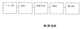
MSでは、イオン源で生成したイオン群を質量分析部にてm/z値ごとに分離し検出する。結果は各イオンのm/z値および相対強度をグラフ化したマススペクトルという形で表わされる。以下、この測定を後述のMS/MS測定に対し、MS測定と呼ぶ。これに対し、イオン源で生成した特定のイオンを初段のMS装置(以下MS1)で選択し(選択されたイオンはプリカーサイオンと呼ばれる)、自発的または強制的に開裂させ、生成したイオン群(開裂生成したイオンはプロダクトイオンと呼ばれる)を後段のMS装置(以下MS2)で質量分析するMS/MS測定があり、それが可能な装置をMS/MS装置と呼ぶ(図1)。
[MS / MS measurement and MS / MS equipment]
In MS, an ion group generated by an ion source is separated and detected for each m / z value by a mass spectrometer. The results are expressed in the form of a mass spectrum that graphs the m / z value and relative intensity of each ion. Hereinafter, this measurement is referred to as MS measurement with respect to the MS / MS measurement described later. On the other hand, specific ions generated by the ion source are selected by the first-stage MS device (hereinafter referred to as MS1) (the selected ions are called precursor ions), and spontaneously or forcibly cleaved, and the generated ions ( There is an MS / MS measurement in which the ion produced by cleavage is called a product ion) by mass spectrometry using a subsequent MS apparatus (hereinafter referred to as MS2), and an apparatus capable of this is called an MS / MS apparatus (FIG. 1).
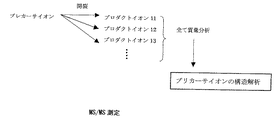
MS/MS測定では、プリカーサイオンのm/z値と複数の開裂経路で生成するプロダクトイオンのm/z値、相対強度情報が得られるため、プリカーサイオンの構造情報を得ることができる(図2)。MS/MS測定を行なうことができるMS/MS装置には、前述の質量分析装置を2つ組み合わせた様々なバリエーションが存在する。また、開裂方法にも、ガスとの衝突による衝突誘起解離(collision induced dissociation: CID)法、光解離法、電子捕獲法などの方法がある。本発明に関連するものは、TOFMSを2台直列に接続し、その間にCID法による開裂手段を配したMS/MS装置であり、一般的にはTOF/TOFと呼ばれている。 In the MS / MS measurement, since the m / z value of the precursor ion, the m / z value of the product ion generated through a plurality of cleavage paths, and the relative intensity information are obtained, the structure information of the precursor ion can be obtained (FIG. 2). ). There are various variations of the MS / MS apparatus capable of performing MS / MS measurement in which two mass spectrometers described above are combined. As the cleavage method, there are methods such as a collision induced dissociation (CID) method, a photodissociation method, and an electron capture method. What is related to the present invention is an MS / MS apparatus in which two TOFMSs are connected in series and a cleavage means based on the CID method is arranged between them, and is generally called TOF / TOF.
さて、CID法を利用したMS/MS装置の解離情報は、衝突エネルギー、すなわち衝突室に入射するイオンの運動エネルギーの高低により異なる。現在利用できるMS/MS装置の場合、数十eV程度の低衝突エネルギー(Low Energy CID)か、数〜数十kVの高衝突エネルギー(High Energy CID)の2種類に分かれる。この差は、装置の構成に左右される。それを表1にまとめる。 Now, the dissociation information of the MS / MS apparatus using the CID method differs depending on the level of collision energy, that is, the kinetic energy of ions incident on the collision chamber. Currently available MS / MS systems are divided into two types: low collision energy (Low Energy CID) of about several tens of eV, and high collision energy (High Energy CID) of several to several tens of kV. This difference depends on the configuration of the device. It is summarized in Table 1.
[飛行時間型質量分析計(TOFMS)]
TOFMSは、一定量のエネルギーを与えてイオンを加速・飛行させ、検出器に到達するまでに要する時間からイオンの質量電荷比を求める質量分析装置である。TOFMSでは、イオンを一定のパルス電圧Vaで加速する。このとき、イオンの速度vは、エネルギー保存則から、
mv2/2 = qeVa ………(1)
v = √(2qeV/m) ………(2)
と表わされる(ただしm:イオンの質量、q:イオンの電荷、e:素電荷)。
[Time of Flight Mass Spectrometer (TOFMS)]
TOFMS is a mass spectrometer that determines the mass-to-charge ratio of ions from the time it takes to reach a detector by accelerating and flying ions with a certain amount of energy. In TOFMS, ions are accelerated with a constant pulse voltage Va. At this time, the ion velocity v is calculated from the energy conservation law.
mv 2/2 = qeV a ......... (1)
v = √ (2qeV / m) (2)
Where m: ion mass, q: ion charge, e: elementary charge.
一定距離Lの後に置いた検出器には、飛行時間Tで到達する。 A detector placed after a certain distance L arrives at a flight time T.
T = L/v = L√(m/2qeV) ………(3)
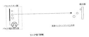
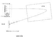
式(3)により、飛行時間Tがイオンの質量mによって異なることを利用して、質量を分離する装置がTOFMSである。図3に直線型TOFMSの一例を示す。また、イオン源と検出器の間に反射場を置くことにより、エネルギー収束性の向上と飛行距離の延長を可能にする反射型TOFMSも広く利用されている。図4に反射型TOFMSの一例を示す。
T = L / v = L√ (m / 2qeV) (3)
TOFMS is a device that separates masses by using the fact that the time of flight T varies depending on the mass m of ions according to equation (3). FIG. 3 shows an example of a linear TOFMS. Reflective TOFMS is also widely used, which can improve energy convergence and extend flight distance by placing a reflection field between the ion source and the detector. FIG. 4 shows an example of a reflective TOFMS.
[らせん軌道TOFMS]
TOFMSの質量分解能は、総飛行時間をT、ピーク幅をΔTとすると、
質量分解能 = T/2ΔT ………(4)
で定義される。すなわち、ピーク幅ΔTを一定にして、総飛行時間Tを延ばすことができれば、質量分解能を向上させられる。しかし、従来の直線型、反射型のTOFMSでは、総飛行時間Tを延ばすこと、すなわち総飛行距離を延ばすことは装置の大型化に直結する。装置の大型化を避け、かつ高質量分解能を実現するために開発された装置が、多重周回型TOFMS(非特許文献1)である。この装置は、円筒電場にマツダプレートを組み合わせたトロイダル電場を4個用い、8の字型の周回軌道を多重周回させることにより、総飛行時間Tを延ばすことができる。この装置では、初期位置、初期角度、初期運動エネルギーによる検出面での空間的な広がりと時間的な広がりを1次の項まで収束させることに成功している。
[Helix orbit TOFMS]
The mass resolution of TOFMS is T, where total flight time is T and peak width is ΔT.
Mass resolution = T / 2ΔT (4)
Defined by That is, if the peak width ΔT is kept constant and the total flight time T can be extended, the mass resolution can be improved. However, in the conventional linear and reflective TOFMS, extending the total flight time T, that is, extending the total flight distance directly leads to an increase in the size of the apparatus. A multi-circular TOFMS (Non-Patent Document 1) is an apparatus developed to avoid an increase in the size of the apparatus and achieve high mass resolution. This device can extend the total flight time T by using four toroidal electric fields in which a Mazda plate is combined with a cylindrical electric field and by making multiple rounds of an 8-shaped orbit. In this apparatus, the spatial extent and temporal extent on the detection surface due to the initial position, initial angle, and initial kinetic energy are successfully converged to the first order term.
しかし、閉軌道を多重周回するTOFMSには、「追い越し」の問題が存在する。これは閉軌道を多重周回するため、軽いイオン(速度大きい)が重いイオン(速度小さい)を追い越してしまうことにより起こる。このため、検出面に軽いイオンから順に到着するというTOFMSの基本概念が通用しなくなる。 However, TOFMS that makes multiple rounds of closed orbits has the problem of “overtaking”. This occurs because light ions (high speed) overtake heavy ions (low speed) because they orbit around the closed orbit. For this reason, the basic concept of TOFMS, which arrives in order from light ions to the detection surface, does not work.
この問題を解決するために考案されたのが、らせん軌道型TOFMSである。らせん軌道型TOFMSは、閉軌道の始点と終点を閉軌道面に対して垂直方向にずらすことを特徴としている。これを実現するためには、イオンをはじめから斜めに入射する方法(特許文献1)や、デフレクタを用いて閉軌道の始点と終点を垂直方向にずらす方法(特許文献2)、積層トロイダル電場を用いる方法(特許文献3)がある。 The helical orbital TOFMS was devised to solve this problem. The helical trajectory type TOFMS is characterized by shifting the start and end points of the closed orbit in the direction perpendicular to the closed orbit plane. In order to realize this, a method in which ions are incident obliquely from the beginning (Patent Document 1), a method in which the start point and end point of a closed orbit are shifted in a vertical direction using a deflector (Patent Document 2), and a laminated toroidal electric field are There is a method used (Patent Document 3).
また、同様のコンセプトとして、追い越しの起こる多重反射型TOFMS(特許文献4)の軌道をジグザグ型にしたTOFMSも考案されている(特許文献5)。 As a similar concept, a TOFMS in which the trajectory of a multiple reflection type TOFMS (Patent Document 4) in which overtaking occurs is made into a zigzag type has also been devised (Patent Document 5).
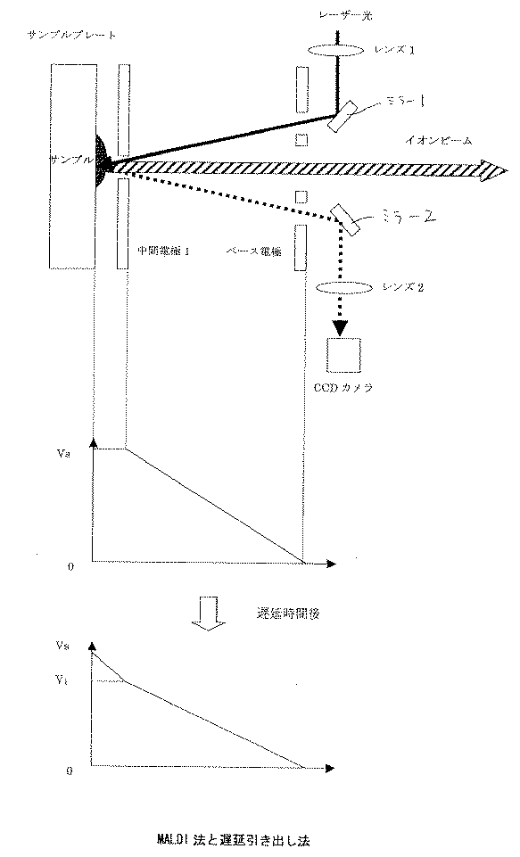
[MALDI法と遅延引き出し法]
MALDI法は、使用するレーザー光波長に吸収帯をもつマトリックス(液体や結晶性化合物、金属粉など)に試料を混合溶解させて固化し、これにレーザー照射して試料を気化あるいはイオン化させる方法である。MALDI法に代表されるレーザーによるイオン化では、イオン生成時の初期エネルギー分布が大きくこれを時間収束させるため、遅延引き出し法がほとんどの場合で用いられる。これは、レーザー照射より数百nsec遅れてパルサー電圧を印加する方法である。
[MALDI method and delayed extraction method]
The MALDI method is a method in which a sample is mixed and dissolved in a matrix (liquid, crystalline compound, metal powder, etc.) that has an absorption band at the wavelength of the laser light to be used, and then the sample is vaporized or ionized by laser irradiation. is there. In ionization with a laser represented by the MALDI method, a delayed extraction method is used in most cases because the initial energy distribution at the time of ion generation is large and this is converged in time. This is a method in which a pulsar voltage is applied with a delay of several hundred nsec from laser irradiation.
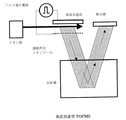
一般的なMALDIイオン源と遅延引き出し法の概念図を図5に示す。サンプルプレート上に、マトリックス(液体や結晶性化合物、金属粉など)に試料を混合溶解させて固化したサンプルを載せる。サンプルの状態が観察できるように、レンズ2、ミラー2、CCDカメラを配置している。レンズ1、ミラー1によりレーザーをサンプルに照射し、サンプルを気化あるいはイオン化する。生成したイオンは、中間電極1、ベース電極に印加された電圧により加速され質量分析部に導入される。
A conceptual diagram of a general MALDI ion source and delayed extraction method is shown in FIG. A sample obtained by mixing and dissolving a sample in a matrix (liquid, crystalline compound, metal powder, etc.) is placed on the sample plate. A
次に遅延引き出し法の飛行時間測定のシーケンスを図5に合わせて示す。まず、中間電極1とサンプルプレートの電位を同電位Vsにしておく。次にレーザー発振を知らせるレーザーからの信号を受けてから、数百nsec後に中間電極1の電位Vsを高速で電位V1に変化させ、サンプルプレートと中間電極1の間に電位勾配を作り、生成したイオンを加速させる。飛行時間計測の開始時間は、パルサーの立ち上がり時間と同期させる。
Next, a sequence of time-of-flight measurement by the delay extraction method is shown in FIG. First, the potential of the
[垂直加速TOFMS]
MALDI法は、パルス的にイオンを生成するため、TOFMSとの相性が非常に良い。しかしながら、質量分析法のイオン化法には、電子衝撃(EI)、化学イオン化(CI)、エレクトロスプレー(ESI)、大気圧化学イオン化(APCI)といった連続的にイオンを生成するイオン化法も数多くある。これらのイオン化法とTOFMSを組み合わせるために開発されたのがOrthogonal Acceleration(垂直加速法)である。
[Vertical acceleration TOFMS]
Since the MALDI method generates ions in a pulsed manner, it is very compatible with TOFMS. However, there are many ionization methods for mass spectrometry such as electron impact (EI), chemical ionization (CI), electrospray (ESI), and atmospheric pressure chemical ionization (APCI). Orthogonal Acceleration (vertical acceleration method) was developed to combine these ionization methods with TOFMS.
図6に垂直加速法を用いたTOFMS(以下垂直加速型TOFMS)の概念図を示す。連続的にイオンを生成するイオン源から生成したイオンビームは、数十eVの運動エネルギーで垂直加速部に連続的に輸送される。垂直加速部では十kV程度のパルス電圧を印加し、イオンをイオン源からの輸送方向に対して垂直方向に加速する。パルス電圧印加後、イオンが検出器に到達するまでの時間が、イオンの質量により異なることから、質量分離を行なう。 FIG. 6 shows a conceptual diagram of TOFMS using the vertical acceleration method (hereinafter referred to as vertical acceleration type TOFMS). An ion beam generated from an ion source that continuously generates ions is continuously transported to the vertical acceleration unit with a kinetic energy of several tens of eV. In the vertical acceleration section, a pulse voltage of about 10 kV is applied to accelerate ions in a direction perpendicular to the transport direction from the ion source. After the pulse voltage is applied, the time until the ions reach the detector varies depending on the mass of the ions, so that mass separation is performed.
[TOF/TOF]
TOFMSを2台直列接続したMS/MS装置は、一般的にTOF/TOFと呼ばれ、主にMALDIイオン源を採用した装置に使用されている。従来のTOF/TOFは、図7に示すように、直線型TOFMSと反射型TOFMSで構成される。その間には、プリカーサイオンを選択するためのイオンゲートが設けられ、イオンゲート付近に第1TOFMSの収束点が配置される。
[TOF / TOF]
An MS / MS system in which two TOFMSs are connected in series is generally called TOF / TOF, and is mainly used in systems that employ a MALDI ion source. As shown in FIG. 7, the conventional TOF / TOF is composed of a linear TOFMS and a reflective TOFMS. In the meantime, an ion gate for selecting a precursor ion is provided, and a convergence point of the first TOFMS is arranged in the vicinity of the ion gate.
イオンゲートにもいくつかの種類があるが、代表的なものには、2枚の電極を対向させた平行平板型、複数のワイヤに交互に極性の異なる電圧を印加するブラドベリー・ニールセン(Bradbury-Nielson)型がある。また、2つのイオンゲートを飛行軸に沿って並べることによりイオンの選択性を上げる方法も提案されている(特許文献6)。 There are several types of ion gates, but a typical one is a parallel plate type with two electrodes facing each other, and Bradbury-Nielsen (Bradbury) Nielson) type. There has also been proposed a method of increasing ion selectivity by arranging two ion gates along the flight axis (Patent Document 6).
プリカーサイオンは、自発的に開裂する(post source decay: PSD)ほか、第1TOFMSもしくは第2TOFMSの反射場以前に配置された衝突室にて強制的に開裂させられる。MALDI-TOF/TOF質量分析計の利点および欠点を次に挙げる。 Precursor ions are not only cleaved spontaneously (post source decay: PSD), but are also forcibly cleaved in a collision chamber placed before the reflection field of the first TOFMS or the second TOFMS. The advantages and disadvantages of the MALDI-TOF / TOF mass spectrometer are listed below.
利点。 advantage.
Pro.1 MALDI法によりイオン化したサンプルを効率良くMS/MS測定できる装置である。 Pro.1 An instrument that can efficiently perform MS / MS measurement of samples ionized by the MALDI method.
Pro.2 高い衝突エネルギー(約20eV)で開裂させることができる数少ない装置の1つである(表1参照)。 Pro.2 One of the few devices that can be cleaved with high impact energy (about 20 eV) (see Table 1).
欠点。 Disadvantage.
Con.1 プリカーサイオン選択性が悪い。 Con.1 Precursor ion selectivity is poor.
Con.2 MS2の質量分解能、質量精度が悪い。 Con.2 Mass resolution and mass accuracy of MS2 are poor.
Con.3 PSDによるプリカーサイオンと、CIDによるプリカーサイオンが混合するため、スペクトルが複雑で解析が困難である。 Con.3 Since the precursor ion by PSD and the precursor ion by CID are mixed, the spectrum is complicated and analysis is difficult.
Con.4 プリカーサイオンを1つしか選択することができず、サンプルの浪費につながる。 Con.4 Only one precursor ion can be selected, leading to wasted sample.
これまでに、上記Con.1、Con.2を克服するための方法はいくつか報告されているので、後述する。しかしながら、Con.3、Con.4は、従来TOF/TOFの原理的な欠点であり、解決することは困難である。 Several methods for overcoming the above Con.1 and Con.2 have been reported so far, and will be described later. However, Con.3 and Con.4 are the fundamental disadvantages of the conventional TOF / TOF and are difficult to solve.
[従来技術の問題点1]
従来技術の問題点の第1は、プリカーサイオンの選択性が悪いことである。プリカーサイオンの選択性は、TOF1の実効飛行距離とイオンゲートの性能とに関連する。従来TOF/TOF装置の第1MSは、前述の通りリニア型TOFMSであることが多い。そのため、実効飛行距離は0.5m程度である。イオンゲートの性能は、空間的、時間的な観点から考える必要がある。図8にはTOF1の実効飛行距離を0.5mとした場合のm/z1000、運動エネルギー20.0kVのイオンを基準にし、m/z999、1000、1001で運動エネルギー20.0keV、19.9keVをもつイオンのTOF1収束点からの前後0.3mの位置に到達する時間差を示した。収束位置(横軸0m)は、TOF1の収束点であり、同じm/z値、異なる運動エネルギーをもつイオンが同時に到着していることが読み取れる。
[
The first problem with the prior art is that the selectivity of precursor ions is poor. The selectivity of the precursor ion is related to the effective flight distance of TOF1 and the performance of the ion gate. The first MS of a conventional TOF / TOF device is often a linear TOFMS as described above. Therefore, the effective flight distance is about 0.5 m. The performance of the ion gate needs to be considered from the viewpoint of space and time. Fig. 8 shows m /
さて、図からm/zが1単位しか違わないイオンは、前後0.1mの位置では時間差がなく、重なり合っていることが分かる。つまり、どんなにイオンゲートの応答時間が速くても分離することはできない。また、重なりのない収束点から前後0.1m以内の位置でもその時間差は、m/z1単位で5ns程度である上に、0.5mmの空間差しかないので分離は不可能である。結果的に、イオンゲートはTOF1の収束点の近傍に置かなければならないという制約がある上、TOF/TOFのプリカーサ選択性は、m/zの前後2単位程度である。
From the figure, it can be seen that the ions whose m / z is different by only one unit are overlapped with no time difference at the position of 0.1 m before and after. In other words, it cannot be separated no matter how fast the response time of the ion gate. Further, even at a position within 0.1 m before and after the convergence point where there is no overlap, the time difference is about 5 ns in m /
[従来技術の問題点2]
従来技術の問題点の第2は、MS2の質量分解能、質量精度が悪いことである。MS2の質量分解能、質量精度が悪い理由には、問題点1およびTOF/TOF装置の利点である高エネルギーCIDであることが大きく関連している。
[
The second problem with the prior art is that the mass resolution and mass accuracy of MS2 are poor. The reason why the mass resolution and mass accuracy of MS2 are poor is largely related to
衝突解離により生成するプロダクトイオンの運動エネルギーUproは、プリカーサイオンの運動エネルギーUpreと質量Mpre、プロダクトイオンの質量mにより、
Upro = (m/Mpre)×Upre
と表わすことができる。たとえば、加速電圧が20kV、プリカーサイオンの価数が1の場合、Upreは20keVであるから、原理的には、0〜20keVの運動エネルギーを持つプロダクトイオン群が開裂生成する。
The kinetic energy Upro of the product ion generated by collisional dissociation is given by the kinetic energy Upre and mass Mpre of the precursor ion, and the mass m of the product ion.
Upro = (m / Mpre) x Upre
Can be expressed as For example, when the acceleration voltage is 20 kV and the valence of the precursor ion is 1, Upre is 20 keV, so in principle, a product ion group having a kinetic energy of 0 to 20 keV is generated by cleavage.
このように、幅広い運動エネルギーをもつイオン群を収束させるために、いくつかの方法が提案されている。減速、開裂、加速により運動エネルギーの分布を抑える方法(特許文献7)、開裂後、ある空間のポテンシャルを急激に変化させた後、再加速する方法(特許文献8)、電界傾斜型の反射場を利用する方法(特許文献9)、再加速とオフセットパラボリックイオンミラー(直線型電界と放物線型電界で構成される反射場)を組み合わせる方法(特許文献10)がある。しかしながら、これらの方法では、非常に幅広い運動エネルギーをもつイオン群のすべてについて収束させることはむづかしく、一般的にMS/MS測定の結果は、反射型TOFMSによるMS測定よりも分解能が悪い。 As described above, several methods have been proposed to converge ions having a wide kinetic energy. Method of suppressing kinetic energy distribution by deceleration, cleavage, and acceleration (Patent Document 7), Method of re-acceleration after abruptly changing the potential of a certain space after cleavage (Patent Document 8), Electric field gradient type reflection field (Patent Document 9), and a method (Patent Document 10) that combines re-acceleration and an offset parabolic ion mirror (a reflection field composed of a linear electric field and a parabolic electric field). However, in these methods, it is difficult to converge all of the ion groups having a very wide kinetic energy, and in general, the results of MS / MS measurement have a lower resolution than MS measurement by reflective TOFMS.
さらに、TOF/TOFの構造に由来して分解能が悪化する。従来技術で述べたように、TOFMSでは、ある測定開始時間で初期分布などを除けば全てのイオンが同じ位置にあることが前提である。しかしながら、TOFMSを直列に接続した場合、TOF1でm/z値に差があるものは分離されていること、プリカーサイオン選択性が悪いため異なるm/z値を有する複数のイオンが第2TOFMSに導入されることなどから、全てのイオンの初期位置が同じではない。そのため、TOF2の質量分解能、質量精度は悪化する。 Furthermore, the resolution deteriorates due to the TOF / TOF structure. As described in the prior art, TOFMS is based on the premise that all ions are in the same position except for the initial distribution at a certain measurement start time. However, when TOFMS is connected in series, the TOF1 with different m / z values is separated, and the precursor ion selectivity is poor, so multiple ions with different m / z values are introduced into the second TOFMS. For example, the initial positions of all ions are not the same. Therefore, the mass resolution and mass accuracy of TOF2 deteriorate.
[従来技術の問題点3]
従来技術の問題点の第3は、MS/MS測定の結果が複雑なことである。TOF/TOF装置の最大の利点は、High Energy CIDが可能な数少ない装置の1つであることである。しかしながら、MALDI法では、PSDが一般的に起こることが知られている。PSD法の開裂経路は、Low Energy CIDの経路に近い。また、従来のTOF/TOF装置では、TOF1がリニアTOFMSであるため、PSDイオンの分離は不可能である。そのため、CIDとPSDによる開裂が同時にMS/MS測定結果に反映される。その結果、問題点2に示したように、MS2の分解能が悪いため、MS/MSスペクトルが非常に複雑になり、解析が困難となる。
[
The third problem of the prior art is that the result of MS / MS measurement is complicated. The greatest advantage of TOF / TOF equipment is that it is one of the few equipment that allows High Energy CID. However, it is known that PSD generally occurs in the MALDI method. The PSD pathway is close to the Low Energy CID pathway. Further, in the conventional TOF / TOF apparatus, since TOF1 is a linear TOFMS, separation of PSD ions is impossible. Therefore, cleavage by CID and PSD is simultaneously reflected in the MS / MS measurement result. As a result, as shown in
[従来技術の問題点4]
従来技術の問題点の第4は、1つのMS/MS測定において、1つのプリカーサイオンからの開裂経路のみしか測定できないことである。表2は、MS/MS測定において、複数のプリカーサイオンの選択を行なう場合に、最初のプリカーサイオンの質量と、次に選択可能となるプリカーサイオンの質量の関係を、従来の直線型TOFMSと反射型TOFMSを結合したTOF/TOF装置で計算したものである。L1は第1TOFMS(直線型)の実効飛行距離、L2は第1TOFMS(反射型)の実効飛行距離であり、L1/L2比を0.5として計算した。
[
A fourth problem of the prior art is that only one cleavage path from one precursor ion can be measured in one MS / MS measurement. Table 2 shows the relationship between the mass of the first precursor ion and the mass of the next precursor ion that can be selected when selecting a plurality of precursor ions in MS / MS measurement. It is calculated with a TOF / TOF device combined with a type TOFMS. L1 is the effective flight distance of the first TOFMS (straight type), L2 is the effective flight distance of the first TOFMS (reflection type), and the L1 / L2 ratio is set to 0.5.
本発明の目的は、上述した点に鑑み、従来のTOF/TOF装置および方法の利点を生かし、欠点を克服した、新しいTOF/TOF装置および方法を提供することにある。 An object of the present invention is to provide a new TOF / TOF apparatus and method that take advantage of the advantages of the conventional TOF / TOF apparatus and method and overcome the drawbacks in view of the above points.
この目的を達成するため、本発明にかかるタンデム型飛行時間型質量分析装置は、
サンプルをイオン化するイオン源と、
生成したイオンをパルス的に加速する加速手段と、
複数の扇形電場で構成され、加速されたイオンをらせん状に飛行させるらせん軌道型の第1の飛行時間型質量分析装置と、
該第1の飛行時間型質量分析装置内に置かれ、特定の質量電荷比を持つイオンのみを選択するイオンゲートと、
該イオンゲートの後段に配置され、選択されたイオンを開裂させるためにガスを充填させた衝突室と、
該衝突室の後段に配置され、開裂したイオンの質量を分析する反射型の第2の飛行時間型質量分析装置と、
該第2の飛行時間型質量分析装置を通過したイオンを検出する検出器と
から成るタンデム型飛行時間型質量分析装置において、
前記第1の飛行時間型質量分析装置は、らせん軌道の周回ごとに飛行方向およびその垂直な面に対する空間的な収束を満たすと共に、
前記イオンゲートは、前記第1の飛行時間型質量分析装置のらせん軌道内に置かれ、該イオンゲートで選択されたイオンは、イオンゲートの後段に配置された前記扇形電場を通過して前記衝突室に入ることを特徴としている。
In order to achieve this object, a tandem time-of-flight mass spectrometer according to the present invention includes:
An ion source for ionizing the sample;
Accelerating means for accelerating the generated ions in a pulsed manner;
A first time-of-flight mass spectrometer of a spiral orbit type, which is composed of a plurality of sector electric fields and spirals accelerated ions;
An ion gate placed in the first time-of-flight mass spectrometer to select only ions having a specific mass to charge ratio;
A collision chamber disposed after the ion gate and filled with a gas to cleave selected ions;
A reflective second time-of-flight mass spectrometer that is disposed downstream of the collision chamber and analyzes the mass of cleaved ions;
A tandem time-of-flight mass spectrometer comprising a detector for detecting ions that have passed through the second time-of-flight mass spectrometer;
The first time-of-flight mass spectrometer satisfies spatial convergence with respect to the flight direction and its vertical plane for each orbit of the spiral trajectory,
The ion gate is placed in a spiral trajectory of the first time-of-flight mass spectrometer, and ions selected by the ion gate pass through the sector electric field arranged at the subsequent stage of the ion gate and collide with the ion gate. It is characterized by entering the room.
また、前記第1の飛行時間型質量分析装置と前記第2の飛行時間型質量分析装置の間に、イオン飛行軌道上とイオン飛行軌道外との間を移動可能なもう1つの検出器を備えたことを特徴としている。 Further, another detector is provided between the first time-of-flight mass spectrometer and the second time-of-flight mass spectrometer, which is movable between an ion flight trajectory and an ion flight trajectory. It is characterized by that.
また、前記第1の飛行時間型質量分析装置を通過したイオンを検出する検出器と、該検出器と前記イオンゲートとの間に存在する扇形電場にイオンが通過する孔を設け、孔を通過したイオンが入射するように前記衝突室と前記第2の飛行時間型質量分析装置を配置するように構成したことを特徴としている。 In addition, a detector that detects the ions that have passed through the first time-of-flight mass spectrometer, and a hole through which the ions pass through a fan-shaped electric field that exists between the detector and the ion gate pass through the holes. The collision chamber and the second time-of-flight mass spectrometer are arranged so that the incident ions are incident.
また、前記イオン通過孔を持つ扇形電場のイオン通過孔を含む階層を他の階層から独立して通電を遮断できるように構成し、前記第1および第2の飛行時間型質量分析装置でタンデム質量分析を行なう場合には、該階層への通電を遮断してイオンが孔を通過するようにしたことを特徴としている。 Further, the hierarchy including the ion passage hole of the sector electric field having the ion passage hole is configured to be able to cut off the current independently from the other hierarchy, and the first and second time-of-flight mass spectrometers use the tandem mass. In the case of performing analysis, it is characterized in that energization to the layer is cut off so that ions pass through the holes.
また、前記通電を遮断にする時間は、プリカーサイオンが通過するタイミングであることを特徴としている。 Further, the time during which the energization is cut off is a timing at which the precursor ions pass.
また、前記らせん軌道上の異なる自由空間で同じ周回角度の位置に、前記複数のゲートとして2つのイオンゲートを配置し、ゲートをON/OFFする電圧が同一電源から供給されることを特徴としている。 Further, two ion gates are arranged as the plurality of gates at positions of the same rounding angle in different free spaces on the spiral trajectory, and voltages for turning the gates ON / OFF are supplied from the same power source. .
また、前記衝突室の前段に減速領域を配置し、衝突室の後段に再加速領域を配置したことを特徴としている。 Further, the present invention is characterized in that a deceleration region is disposed in the front stage of the collision chamber and a reacceleration region is disposed in the rear stage of the collision chamber.
また、前記第2の飛行時間型質量分析装置における反射場が、曲線状のポテンシャル分布を持つイオンミラーであることを特徴としている。 Further, the reflection field in the second time-of-flight mass spectrometer is an ion mirror having a curved potential distribution.
また、前記衝突室の後段に再加速領域を配置すると共に、前記第2の飛行時間型質量分析装置における反射場内のポテンシャルが直線と放物線を直列に組み合わせた形状のイオンミラーであることを特徴としている。 In addition, a reacceleration region is arranged at the rear stage of the collision chamber, and the potential in the reflection field in the second time-of-flight mass spectrometer is an ion mirror having a shape in which a straight line and a parabola are combined in series. Yes.
また、前記第2の飛行時間型質量分析装置を構成する反射場は、複数の電極で構成され、各電極に供給される電圧が両端の電極に接続された接地電位を挟む両極性の2つの電源と、隣り合う電極間を接続する抵抗とにより分割供給される場合、両極に挟まれた間に位置する1つの電極を接地電位に設定することを特徴としている。
Further, the second reflected field constituting the time-of-flight mass spectrometer is composed of a plurality of electrodes, the voltage of two bipolar sandwiching a ground potential connected to the electrodes at both ends to be supplied to each electrode If the power and is divided supplied by resistors and connecting between adjacent electrodes, it is characterized by setting one of the electrodes located between sandwiched poles to the ground potential.
また、前記イオン源でのイオン化法が、導電性のサンプルプレート上のサンプルをレーザー光照射によりイオン化する方法であることを特徴としている。 Further, the ionization method using the ion source is characterized in that a sample on a conductive sample plate is ionized by laser light irradiation.
また、前記イオン化法が、MALDI法であることを特徴としている。 Further, the ionization method is a MALDI method.
また、前記イオンを加速する手段が、遅延引き出し法であることを特徴としている。 The means for accelerating the ions is a delayed extraction method.
また、前記イオン源からイオンをパルス的に加速する加速手段が、連続型イオン源で生成したイオンを低エネルギーで輸送してパルス的に加速する垂直加速法であることを特徴としている。
また、本発明にかかるタンデム型飛行時間型質量分析方法は、
前記タンデム型飛行時間型質量分析装置を用い、1回の飛行時間測定において複数のプリカーサイオンを選択してMS/MS測定を行なうことを特徴としている。
Further, the acceleration means for accelerating ions from the ion source in a pulsed manner is a vertical acceleration method in which ions generated from the continuous ion source are transported with low energy and accelerated in a pulsed manner.
The tandem time-of-flight mass spectrometry method according to the present invention is
The tandem time-of-flight mass spectrometer is used to perform MS / MS measurement by selecting a plurality of precursor ions in one time-of-flight measurement.
また、前記複数のプリカーサイオンが、すべてモノアイソトピックイオンであることを特徴としている。 In addition, the plurality of precursor ions are all monoisotopic ions.
本発明のタンデム型飛行時間型質量分析装置によれば、
サンプルをイオン化するイオン源と、
生成したイオンをパルス的に加速する加速手段と、
複数の扇形電場で構成され、加速されたイオンをらせん状に飛行させるらせん軌道型の第1の飛行時間型質量分析装置と、
該第1の飛行時間型質量分析装置内に置かれ、特定の質量電荷比を持つイオンのみを選択する複数のイオンゲートと、
該イオンゲートの後段に配置され、選択されたイオンを開裂させるためにガスを充填させた衝突室と、
該衝突室の後段に配置され、開裂したイオンの質量を分析する反射型の第2の飛行時間型質量分析装置と、
該第2の飛行時間型質量分析装置を通過したイオンを検出する検出器と
から成るタンデム型飛行時間型質量分析装置において、
前記第1の飛行時間型質量分析装置は、らせん軌道の周回ごとに飛行方向およびその垂直な面に対する空間的な収束を満たすと共に、
前記複数のイオンゲートは、前記第1の飛行時間型質量分析装置のらせん軌道内の異なる自由空間で同じ周回角度の複数の位置に置かれ、該イオンゲートで選択されたイオンは、すべてのイオンゲートを通過後、更にイオンゲートの後段に配置された前記扇形電場を通過して前記衝突室に入るので、
従来のタンデム型飛行時間型質量分析装置の利点を生かし、欠点を克服した、新しいタンデム型飛行時間型質量分析装置を提供することが可能になった。
According to the tandem time-of-flight mass spectrometer of the present invention,
An ion source for ionizing the sample;
Accelerating means for accelerating the generated ions in a pulsed manner;
A first time-of-flight mass spectrometer of a spiral orbit type, which is composed of a plurality of sector electric fields and spirals accelerated ions;
A plurality of ion gates placed in the first time-of-flight mass spectrometer and selecting only ions having a specific mass-to-charge ratio;
A collision chamber disposed after the ion gate and filled with a gas to cleave selected ions;
A reflective second time-of-flight mass spectrometer that is disposed downstream of the collision chamber and analyzes the mass of cleaved ions;
A tandem time-of-flight mass spectrometer comprising a detector for detecting ions that have passed through the second time-of-flight mass spectrometer;
The first time-of-flight mass spectrometer satisfies spatial convergence with respect to the flight direction and its vertical plane for each orbit of the spiral trajectory,
The plurality of ion gates are placed at a plurality of positions at the same rounding angle in different free spaces in the spiral orbit of the first time-of-flight mass spectrometer, and ions selected by the ion gate are all ions. After passing through the gate and further passing through the sector electric field arranged at the subsequent stage of the ion gate and entering the collision chamber,
It has become possible to provide a new tandem time-of-flight mass spectrometer that takes advantage of the advantages of the conventional tandem time-of-flight mass spectrometer and overcomes the drawbacks.
また、本発明のタンデム型飛行時間型質量分析方法によれば、
前記タンデム型飛行時間型質量分析装置を用い、1回の飛行時間測定において複数のプリカーサイオンを選択してMS/MS測定を行なうので、
従来のタンデム型飛行時間型質量分析方法の利点を生かし、欠点を克服した、新しいタンデム型飛行時間型質量分析方法を提供することが可能になった。
Further, according to the tandem time-of-flight mass spectrometry method of the present invention,
Since the tandem time-of-flight mass spectrometer is used to perform MS / MS measurement by selecting a plurality of precursor ions in one time-of-flight measurement,
It has become possible to provide a new tandem time-of-flight mass spectrometry method that takes advantage of the conventional tandem time-of-flight mass spectrometry method and overcomes the drawbacks.
以下、図面を参照して、本発明の実施の形態を説明する。本実施例の記述では、4つの扇形電場で構成されるらせん軌道TOFMSを第1TOFに利用した例を挙げるが、ジグザグ軌道の多重反射型についても同様のことが言える。また、MALDI法をイオン源に採用した場合について述べるが、垂直加速法を応用して連続イオン源に接続した場合についても同様である。さらに、第2TOFとして、再加速とオフセットパラボリックイオンミラーについて述べるが、他の運動エネルギー圧縮方法、他のイオンミラーを用いても良い。 Embodiments of the present invention will be described below with reference to the drawings. In the description of the present embodiment, an example in which a spiral orbit TOFMS composed of four sector electric fields is used as the first TOF is described, but the same can be said for a zigzag orbit multiple reflection type. Although the case where the MALDI method is adopted as the ion source will be described, the same applies to the case where the vertical acceleration method is applied to connect to the continuous ion source. Furthermore, although reacceleration and an offset parabolic ion mirror will be described as the second TOF, other kinetic energy compression methods and other ion mirrors may be used.
[実施例1]
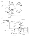
図9は本発明にかかる第1の実施の形態例を示す図である。(a)は装置をZ方向に見た図、(b)は(a)図の矢印方向(Y方向)から見た図である。図において、11はMALDIイオン源、12〜15はZ方向に多層に積層されて8の字形のらせん軌道を形作る扇形電場、16はプリカーサイオンを選択するイオンゲート、17はイオンを開裂させる衝突室、18はらせん軌道TOFMS(以下第1TOFMS)と反射型TOFMS(以下第2TOFMS)の間に形成された一定電圧またはパルス電圧によるイオンの再加速領域、19は衝突室17で開裂したイオンが入射される反射場で、この場合はオフセットパラボリックイオンミラー、20は反射場19を反射したイオンが検出される検出器である。尚、衝突室17の前段にイオンの減速領域を設けても良い。
[Example 1]
FIG. 9 is a diagram showing a first embodiment according to the present invention. (A) is the figure which looked at the apparatus to the Z direction, (b) is the figure seen from the arrow direction (Y direction) of (a) figure. In the figure, 11 is a MALDI ion source, 12 to 15 are fan-shaped electric fields that are stacked in multiple layers in the Z direction to form an 8-shaped spiral trajectory, 16 is an ion gate that selects precursor ions, and 17 is a collision chamber that cleaves ions. , 18 is a re-acceleration region of ions by a constant voltage or pulse voltage formed between a spiral orbit TOFMS (hereinafter referred to as a first TOFMS) and a reflective TOFMS (hereinafter referred to as a second TOFMS), and 19 is an ion which is cleaved in a collision chamber In this case, an offset parabolic ion mirror, and 20 is a detector for detecting ions reflected from the
本実施例の最大の特徴は、イオンゲート16の後段に、さらに扇形電場の一部が配置されていて、イオンゲート16を通過した後にイオンの自発的な開裂によってできたプロダクトイオンを第2TOFMS側に通過させないように、扇形電場の一部をマスフィルターとして利用するように工夫されていることである。このように構成された装置の動作を説明すれば、以下の通りである。
The greatest feature of this embodiment is that a part of the sector electric field is further arranged at the rear stage of the
まずMALDIイオン源にてサンプル化合物群をイオン化し、遅延引き出し法にてイオンを加速する。第1TOFMSのイオン光学系は、8の字らせんの各周で飛行方向およびその垂直な面に対して空間的な収束を満たすように設計されている。第2TOFMSも運動エネルギー収束性をもつ系であるので、遅延引き出し法による収束点F1は、再加速領域18の始点に設定する。サンプルイオン群は、第1TOFMS、第2TOFMSを飛行する間に、質量電荷比ごとに分離され、MS測定の場合、検出器20で検出される。
First, sample compound groups are ionized with a MALDI ion source, and ions are accelerated by a delayed extraction method. The ion optics of the first TOFMS is designed to satisfy spatial convergence with respect to the flight direction and its perpendicular plane at each circumference of the 8-shaped helix. Since the second TOFMS is also a system having kinetic energy convergence, the convergence point F1 by the delay extraction method is set to the start point of the
前述の通り、従来のTOF/TOFでは、この収束点付近にイオンゲートを配置しなければならない上に、プリカーサイオンの選択性が非常に悪かった。それに対して、らせん軌道TOFMSを第1TOFMSに採用することで、イオンゲートまでの実効飛行距離を延長でき、収束点に関わらず、高いプリカーサイオン選択性を実現することができる。 As described above, in the conventional TOF / TOF, an ion gate must be arranged near the convergence point, and the selectivity of the precursor ion is very poor. On the other hand, by adopting spiral orbit TOFMS as the first TOFMS, the effective flight distance to the ion gate can be extended, and high precursor ion selectivity can be realized regardless of the convergence point.
図10には、収束点までの実効飛行距離(F1までの距離+周回軌道の長さ)を10mとした場合に、m/z1000、運動エネルギー20.0kVのイオンを基準にしたm/z999、1000、1001で運動エネルギー20.0keV、19.9keVをもつイオンの第1TOF収束点からの前後0.3mの位置に到達する時間差を示した。イオンゲートの位置でのイオンパケットの状態は、F2の位置と同じである。F1とF2までの距離差を0.2m〜0.3m程度と仮定すると、イオンゲートの位置は、図の−0.2m〜−0.3mの間である。図10から明らかなように、収束点F1から0.2m程度離れていても、m/z1単位異なるイオンは空間的、時間的に良く分離されていて、高いプリカーサイオン選択性を実現できることが分かる。また、扇形電場は、通過することにできる位置および角度のずれについての規制が厳しいため、イオンゲートを扇形電場の前に配置することにより、単純なイオンゲートよりも高いプリカーサイオン選択性を得ることができる。
FIG. 10 shows m /
選択されたプリカーサイオンは、衝突室17に入射し、内部に充填されたガスとの衝突により開裂を起こし、プロダクトイオンを生成する。このとき、第1TOFMSを構成する扇形電場は、運動エネルギーフィルタの機能を持つので、第1TOFMS飛行中にPSDにより開裂生成するイオンを排除することができる。つまり、高エネルギーCIDのみのマススペクトルを得ることができる。
The selected precursor ions enter the
全てのプロダクトイオンおよびプリカーサイオンは、一定電圧またはパルス電圧による再加速領域18にて再加速され、運動エネルギーを圧縮された後、オフセットパラボリックイオンミラー19とその前後の自由空間、および検出器20で構成される第2TOFMSにて、m/z値ごとに分離され、検出器20にて検出される。
All the product ions and precursor ions are re-accelerated in the
通常の有機物を測定したマススペクトルには、構成元素の同位体に由来する同位体ピークが観測される。その中で、最も質量の小さいピーク、すなわち構成元素のうち最も小さい質量の同位体のみで構成されたイオンは、モノアイソトピックイオンと呼ばれ、それを示すピークは、モノアイソトピックピークと呼ばれている。 Isotope peaks derived from isotopes of constituent elements are observed in mass spectra obtained by measuring ordinary organic substances. Among them, the peak with the smallest mass, that is, the ion composed only of the isotopes with the smallest mass among the constituent elements is called the monoisotopic ion, and the peak indicating it is called the monoisotopic peak. ing.
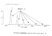
図11は、アンギオテンシンI(C62H90N17O14 +)の同位体ピークとモノアイソトピックピークを示したものである。高いプリカーサイオン選択性の利点は、構成元素の最も質量数の小さい同位体のみから成るモノアイソトピックイオンを選択した場合に顕著である。つまり、そのプロダクトイオンも最も質量の小さい同位体のみで構成されるので、1つの組成に対して1本のピークのみ表われ、複雑なCIDのMS/MSスペクトルを単純化できる。 FIG. 11 shows an isotope peak and monoisotopic peak of angiotensin I (C 62 H 90 N 17 O 14 + ). The advantage of high precursor ion selectivity is remarkable when a monoisotopic ion consisting only of an isotope having the smallest mass number of the constituent elements is selected. That is, since the product ion is also composed of only the isotope having the smallest mass, only one peak appears for one composition, and the MS / MS spectrum of a complicated CID can be simplified.
また、MALDI法を用いる場合、MS測定にて大量のマトリクス由来イオンがm/z<500に観測される。前述のイオンゲートによってマトリクス由来イオンなど高強度のイオンを排除するイオンゲートとして用いることも可能である。 In addition, when the MALDI method is used, a large amount of matrix-derived ions are observed at m / z <500 by MS measurement. It is also possible to use the ion gate as an ion gate that excludes high-intensity ions such as matrix-derived ions.
[実施例2]
本実施例は、図12に示すように、実施例1にMS測定用の検出器21を追加したものである。通常、衝突室17は気密性を確保するため、イオンの出入り口は1mmφ程度である。そのため、MS測定において衝突室17を通過したイオンを検出することは、感度面で不利になる可能性もある。また、前述の通り、遅延引き出し法においてサンプルプレートから収束点までの距離を短くすることで、MS測定における質量分解能の質量依存性を低減することができる。これらの理由により、MS測定およびMS/MS測定両者においてより良いデータを取得するためには、遅延引き出し法の収束点を変える方法が有効である。
[Example 2]
In the present embodiment, as shown in FIG. 12, an
まずMALDIイオン源にてサンプル化合物群をイオン化し、遅延引き出し法にてイオンを加速する。第1TOFMSのイオン光学系は、8の字らせんの各周で飛行方向およびその垂直な面に対して空間的な収束を満たすように設計されている。つまり、らせん軌道最終周の検出器21の位置に相当する位置F2に遅延引き出し法による収束点を設定すれば良い。サンプルイオン群は、らせん軌道の第1TOFMSにて質量電荷比ごとに分離され、MS測定の場合、検出器21で検出される。MALDI法を用いる場合、大量のマトリクスイオンが生成する場合が多い。検出器21以前の周回に配置されたイオンゲート16によってマトリクスイオンなど高強度のイオンを排除することが可能である。
First, sample compound groups are ionized with a MALDI ion source, and ions are accelerated by a delayed extraction method. The ion optics of the first TOFMS is designed to satisfy spatial convergence with respect to the flight direction and its perpendicular plane at each circumference of the 8-shaped helix. That is, a convergence point by the delay extraction method may be set at a position F2 corresponding to the position of the
MS/MS測定の場合は、検出器21をイオン軌道上から外し、イオンを通過可能とする。また、第2TOFMSの始点である再加速領域18の始点が収束点となるよう、遅延引き出し法の収束点を位置F2となるように条件設定する。実施例1で記載した通り、収束点F1から0.2m〜0.3m程度離れたF1の位置付近では、m/zで1単位異なるイオン同士が空間的、時間的に良く分離されており、ここにイオンゲートを配置すれば、高いプリカーサイオン選択性を実現できる。
In the case of MS / MS measurement, the
選択されたプリカーサイオンは、衝突室17に入射し、内部に充填されたガスとの衝突により開裂を起こし、プロダクトイオンを生成する。このとき、第1TOFMSを構成する扇形電場は、運動エネルギーフィルタの機能を持つので、第1TOFMS飛行中にPSDにより開裂生成するイオンを排除することができる。つまり、高エネルギーCIDのみのマススペクトルを得ることができる。
The selected precursor ions enter the
全てのプロダクトイオンおよびプリカーサイオンは、一定電圧またはパルス電圧による再加速領域18にて再加速され、運動エネルギーを圧縮された後、オフセットパラボリックイオンミラー19とその前後の自由空間、および検出器20で構成される第2TOFMSにて、m/z値ごとに分離され、検出器20にて検出される。
All the product ions and precursor ions are re-accelerated in the
[実施例3]
本実施例は、図13に示すように、実施例2の一部を変更したものである。本実施例では、検出器21が配置された周回数よりは前で、かつイオンゲート16が配置された周回数よりは後ろの扇形電場にイオン通過孔22を設け、イオン通過孔から直線状に延びる飛行軌道の延長線上に、衝突室17、再加速領域18、オフセットパラボリックイオンミラー19、検出器20を配置している。
[Example 3]
In this embodiment, a part of the second embodiment is changed as shown in FIG. In the present embodiment, an ion passage hole 22 is provided in a fan-shaped electric field before the number of turns in which the
MS測定の場合、このイオン通過孔22を持つ扇形電場に電圧を印加しておき、イオンにこのイオン通過孔22を通過させることなく、らせん軌道上を飛行させる。MS/MS測定の場合は、イオンゲート16で選択したイオンがイオン通過孔22を通過するために、扇形電場の電場をなくす必要がある。多層に積層されて8の字形のらせん軌道を形作る扇形電場の全ての階層が導通されており、同じ電源から電圧が供給されている場合は、選択したプリカーサイオンが通過する瞬間のみ電圧をOFFにすれば良い。また、イオン通過孔を持つ階層のみが他の階層から絶縁されている場合は、その階層に電圧のON/OFFを切り替えるスイッチを配置することで、MS測定モードとMS/MS測定モードを切り替えるようにしても良い。
In the case of MS measurement, a voltage is applied to a sector electric field having the ion passage hole 22 and the ions are allowed to fly on the spiral trajectory without passing through the ion passage hole 22. In the case of MS / MS measurement, since the ions selected by the
[実施例4]
本実施例は、図14に示すように、実施例1〜3のイオンゲートを変更したものである。実施例1では、m/z1単位の違いを分離できるプリカーサイオン選択能を持つが、装置の小型化やより高い選択性実現のために、イオンゲートの応答時間を速くする必要もある。その場合、従来技術でも説明したように、2つのイオンゲートを利用する方法がある。例えば、MALDIイオン源に近い側のイオンゲートで選択すべきプリカーサイオンよりm/z値の小さなイオンを排除し、検出器に近い側のイオンゲートでプリカーサイオンよりm/z値の大きなイオンを排除する。
[Example 4]
In this embodiment, as shown in FIG. 14, the ion gates of
実施例1〜3で述べた通り、従来TOF/TOFでは、イオンゲートはTOF1収束点付近に配置する必要があったが、本装置ではイオンゲートの位置は比較的自由に設定できる。そのため、2つのイオンゲートを用いる場合には、様々な配置方法がある。しかしながら、イオンゲートへの電圧供給線の延長は、イオンゲートそのものの応答を悪化させる。そのことを勘案すると、図14(a)のように同じ階層の空間に配置したり、図14(b)のように異なる階層の比較的近い位置に置いたりしても良い。図14(c)は、ブラドベリー・ニールセン(Bradbury-Nielson)型のイオンゲートの構造を異なる階層間にまたがらせることにより、構造物としては1つにまとめたものである。もちろん、平行平板型のイオンゲートでも同じことが可能である。 As described in the first to third embodiments, in the conventional TOF / TOF, the ion gate needs to be arranged in the vicinity of the TOF1 convergence point, but in this apparatus, the position of the ion gate can be set relatively freely. Therefore, there are various arrangement methods when two ion gates are used. However, extension of the voltage supply line to the ion gate deteriorates the response of the ion gate itself. Considering this, it may be arranged in the space of the same hierarchy as shown in FIG. 14A, or may be placed in a relatively close position of different hierarchy as shown in FIG. 14B. FIG. 14C summarizes the structure of a Bradbury-Nielson type ion gate as one structure by spanning different layers. Of course, the same is possible with a parallel plate ion gate.
[実施例5]
本実施例は、サンプルの浪費を減らすため、同じレーザー照射による測定で、複数のプリカーサイオンを選択する方法を示したものである。本実施例では、実施例1を変更した例を挙げているが、実施例2〜4においても同様のことができる。
[Example 5]
The present embodiment shows a method of selecting a plurality of precursor ions by the same laser irradiation measurement in order to reduce sample waste. In the present embodiment, an example in which the first embodiment is changed is described, but the same can be applied to the second to fourth embodiments.
まずMALDIイオン源にてサンプル化合物群をイオン化し、生成したイオンをパルス電圧にて加速する。イオン化によってサンプル化合物群はサンプルイオン群となる。第1TOFMSにてサンプルイオン群を質量電荷比ごとに分離する。第1TOFMSを通過したサンプルイオン群は、イオンゲートにて選択される。選択されたプリカーサイオンは、衝突室に入射し、内部に充填されたガスとの衝突により開裂を起こし、プロダクトイオンを生成する。プリカーサイオンおよびプロダクトイオンは、検出器にて検出される。 First, a sample compound group is ionized with a MALDI ion source, and the generated ions are accelerated by a pulse voltage. By ionization, the sample compound group becomes a sample ion group. Sample ions are separated by mass-to-charge ratio in the first TOFMS. The sample ion group that has passed through the first TOFMS is selected by an ion gate. The selected precursor ions enter the collision chamber and are cleaved by collision with the gas filled therein to produce product ions. Precursor ions and product ions are detected by a detector.
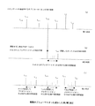
次に、複数のプリカーサイオンを選択するMS/MS測定の動作について図15を用いて説明する。今、説明のために、MALDIイオン源にてサンプル由来の7つのプリカーサイオンPre1〜Pre7があるとする。それぞれの価数は1価とし、質量の関係は、番号の若い順に小さいものとする。各イオンはMALDIイオン源にて加速され、第1TOFMSにて質量分離した後、図15(a)に示すように、質量の小さい順にイオンゲートに到達する。 Next, the operation of MS / MS measurement for selecting a plurality of precursor ions will be described with reference to FIG. For the sake of explanation, assume that there are seven precursor ions Pre1 to Pre7 derived from a sample in the MALDI ion source. Each valence is assumed to be monovalent, and the mass relationship is assumed to be smaller in ascending order of numbers. Each ion is accelerated by the MALDI ion source, mass-separated by the first TOFMS, and then reaches the ion gate in ascending order of mass as shown in FIG.
各プリカーサイオンPreNのイオンゲート到達時間をTN,IGとする。まず、1つのプリカーサイオンPre4を選択した場合のMS/MS測定の場合を考える。イオンゲートでPre4のみを選択して衝突室に導入すると、開裂を起こしプロダクトイオンを生成する場合と、開裂を起こさずプリカーサイオンのまま衝突室を通過する場合とがある。開裂が起こる場合、プリカーサイオンの持つ運動エネルギーUpre4は、開裂時にプロダクトイオンの質量に比例して配分される。すなわち、プロダクトイオンの運動エネルギーUproは、m/Mpre4×Upre4(mはプロダクトイオンの質量)となる。 The arrival time of each precursor ion PreN in the ion gate is defined as TN, IG . First, consider the case of MS / MS measurement when one precursor ion Pre4 is selected. When only Pre4 is selected by the ion gate and introduced into the collision chamber, there are a case where cleavage occurs and product ions are generated, and a case where the precursor ion is passed through the collision chamber without cleavage. When cleavage occurs, the kinetic energy U pre4 of the precursor ion is distributed in proportion to the mass of the product ion at the time of cleavage. That is, the kinetic energy U pro of the product ion is m / M pre4 × U pre4 (m is the mass of the product ion).
続いてプリカーサイオンとプロダクトイオンは、第2TOFMSに導入される。反射型TOFMSの反射場では、運動エネルギーの小さなイオンが先に折り返し、検出器に到達するため、プリカーサイオンが最後に検出器に到達することとなる。各プリカーサイオンPreNの検出器到達時間をTN,Dとする。つまり、Pre4を選択した場合のMS/MSスペクトルは、図15(b)のように、T4,IG〜T4,Dの間を測定すれば良い。 Subsequently, precursor ions and product ions are introduced into the second TOFMS. In the reflection field of the reflective TOFMS, the ion with small kinetic energy first turns back and reaches the detector, so that the precursor ion finally reaches the detector. Let T N, D be the detector arrival time of each precursor ion PreN. That is, the MS / MS spectrum when Pre4 is selected may be measured between T4 , IG and T4 , D as shown in FIG.
このように、それぞれのプリカーサイオンのMS/MS測定に必要な飛行時間範囲は、容易に計算することができ、お互いの飛行時間範囲が干渉し合わなければ、同一の飛行時間測定において複数のMS/MS測定が可能であることが分かる。 In this way, the time-of-flight range required for MS / MS measurement of each precursor ion can be easily calculated. If the time-of-flight ranges do not interfere with each other, multiple MSs can be measured in the same time-of-flight measurement. It turns out that / MS measurement is possible.
このような状況を実現するためには、イオンゲートでの各プリカーサイオンの飛行時間間隔が、MS/MS測定に必要な飛行時間範囲よりも大きければ良い。そのためには、第1TOFMSの実効飛行距離L1と第2TOFMSの実効飛行距離L2の比L1/L2を大きくする必要がある。らせん軌道TOFMSは、従来の反射型TOFMSと比較して10倍程度の長い実効飛行距離を実現できるため、らせん軌道TOFMSと反射型TOFMSを組み合わせることで同一の飛行時間測定において複数のプリカーサイオンを選択したMS/MS測定が可能である。 In order to realize such a situation, it is sufficient that the flight time interval of each precursor ion at the ion gate is larger than the flight time range required for MS / MS measurement. For this purpose, it is necessary to increase the ratio L1 / L2 between the effective flight distance L1 of the first TOFMS and the effective flight distance L2 of the second TOFMS. Spiral orbit TOFMS can achieve an effective flight distance that is about 10 times longer than conventional reflective TOFMS. Therefore, by combining helical orbit TOFMS and reflective TOFMS, multiple precursor ions can be selected for the same time-of-flight measurement. MS / MS measurement is possible.
次に、この議論をより定量的に行なう。表3は、複数のプリカーサイオンを選択するMS/MS測定において、最初のプリカーサイオンの質量と、次に選択可能となるプリカーサイオンの質量の関係を、L1/L2比および最初に選択するプリカーサイオンの質量を変化させ、計算した結果である。 Next, this discussion will be conducted more quantitatively. Table 3 shows the relationship between the mass of the first precursor ion and the mass of the precursor ion that can be selected next in the L / L2 ratio and the first selected precursor ion in MS / MS measurement in which a plurality of precursor ions are selected. It is the result of changing the mass of and calculating.
[実施例6]
イオンミラーは、図16(a)に示すように、数十枚程度の複数の穴あき電極を並べ、その両端に電源を供給し、中間の電極へは抵抗分割により電圧を供給する場合が多い。多くの場合、イオンミラーの両端の電圧は、グランド電位を挟んで逆極性の場合が多い。それぞれの電源には、微小な電圧の振れ(リップル)や温度変化などによる経時的な変化(ドリフト)が存在するが、各電極に供給される電圧のリップルやドリフトは、両端に接続された電源の変化が合算される形となる。本実施例では、図16(b)に示すように、グランド電位を挟んで逆極性の場合に、1つの電極をグランド電位と接続することで、電源の変化の影響を抑え、各電極の電源精度、つまり測定における飛行時間精度を向上させることができる。
[Example 6]
In the ion mirror, as shown in FIG. 16 (a), several tens of perforated electrodes are arranged, power is supplied to both ends thereof, and a voltage is often supplied to the intermediate electrode by resistance division. . In many cases, the voltage across the ion mirror is often opposite in polarity with respect to the ground potential. Each power supply has minute voltage fluctuations (ripples) and changes over time (drifts) due to temperature changes, but the voltage ripples and drifts supplied to each electrode are connected to both ends. The changes will be added together. In this embodiment, as shown in FIG. 16B, in the case of a reverse polarity across the ground potential, by connecting one electrode to the ground potential, the influence of the change in the power source is suppressed, and the power source of each electrode Accuracy, that is, time-of-flight accuracy in measurement can be improved.
飛行時間型質量分析装置のタンデム測定に広く利用できる。 It can be widely used for tandem measurement of time-of-flight mass spectrometers.
11:MALDIイオン源、12:扇形電場1、13:扇形電場2、14:扇形電場3、15:扇形電場4、16:イオンゲート、17:衝突室、18:再加速領域、19:オフセットパラボリックイオンミラー、20:検出器、21:検出器、22:イオン通過孔
11: MALDI ion source, 12: sector
Claims (16)
生成したイオンをパルス的に加速する加速手段と、
複数の扇形電場で構成され、加速されたイオンをらせん状に飛行させるらせん軌道型の第1の飛行時間型質量分析装置と、
該第1の飛行時間型質量分析装置内に置かれ、特定の質量電荷比を持つイオンのみを選択する複数のイオンゲートと、
該イオンゲートの後段に配置され、選択されたイオンを開裂させるためにガスを充填させた衝突室と、
該衝突室の後段に配置され、開裂したイオンの質量を分析する反射型の第2の飛行時間型質量分析装置と、
該第2の飛行時間型質量分析装置を通過したイオンを検出する検出器と
から成るタンデム型飛行時間型質量分析装置において、
前記第1の飛行時間型質量分析装置は、らせん軌道の周回ごとに飛行方向およびその垂直な面に対する空間的な収束を満たすと共に、
前記複数のイオンゲートは、前記第1の飛行時間型質量分析装置のらせん軌道内の異なる自由空間で同じ周回角度の複数の位置に置かれ、該イオンゲートで選択されたイオンは、すべてのイオンゲートを通過後、更にイオンゲートの後段に配置された前記扇形電場を通過して前記衝突室に入ることを特徴とするタンデム型飛行時間型質量分析装置。 An ion source for ionizing the sample;
Accelerating means for accelerating the generated ions in a pulsed manner;
A first time-of-flight mass spectrometer of a spiral orbit type, which is composed of a plurality of sector electric fields and spirals accelerated ions;
A plurality of ion gates placed in the first time-of-flight mass spectrometer and selecting only ions having a specific mass-to-charge ratio;
A collision chamber disposed after the ion gate and filled with a gas to cleave selected ions;
A reflective second time-of-flight mass spectrometer that is disposed downstream of the collision chamber and analyzes the mass of cleaved ions;
A tandem time-of-flight mass spectrometer comprising a detector for detecting ions that have passed through the second time-of-flight mass spectrometer;
The first time-of-flight mass spectrometer satisfies spatial convergence with respect to the flight direction and its vertical plane for each orbit of the spiral trajectory,
The plurality of ion gates are placed at a plurality of positions at the same rounding angle in different free spaces in the spiral orbit of the first time-of-flight mass spectrometer, and ions selected by the ion gate are all ions. A tandem time-of-flight mass spectrometer characterized by entering the collision chamber after passing through the gate and then passing through the electric sector electric field arranged at the subsequent stage of the ion gate.
Priority Applications (1)
| Application Number | Priority Date | Filing Date | Title |
|---|---|---|---|
| JP2007321479A JP5259169B2 (en) | 2007-01-10 | 2007-12-13 | Tandem time-of-flight mass spectrometer and method |
Applications Claiming Priority (3)
| Application Number | Priority Date | Filing Date | Title |
|---|---|---|---|
| JP2007001997 | 2007-01-10 | ||
| JP2007001997 | 2007-01-10 | ||
| JP2007321479A JP5259169B2 (en) | 2007-01-10 | 2007-12-13 | Tandem time-of-flight mass spectrometer and method |
Publications (2)
| Publication Number | Publication Date |
|---|---|
| JP2008192600A JP2008192600A (en) | 2008-08-21 |
| JP5259169B2 true JP5259169B2 (en) | 2013-08-07 |
Family
ID=39510033
Family Applications (1)
| Application Number | Title | Priority Date | Filing Date |
|---|---|---|---|
| JP2007321479A Active JP5259169B2 (en) | 2007-01-10 | 2007-12-13 | Tandem time-of-flight mass spectrometer and method |
Country Status (3)
| Country | Link |
|---|---|
| US (1) | US7755036B2 (en) |
| JP (1) | JP5259169B2 (en) |
| DE (1) | DE102007060669B4 (en) |
Families Citing this family (34)
| Publication number | Priority date | Publication date | Assignee | Title |
|---|---|---|---|---|
| US7663100B2 (en) * | 2007-05-01 | 2010-02-16 | Virgin Instruments Corporation | Reversed geometry MALDI TOF |
| WO2009066354A1 (en) * | 2007-11-21 | 2009-05-28 | Shimadzu Corporation | Mass spectrometry device |
| US20110248161A1 (en) * | 2008-10-02 | 2011-10-13 | Shimadzu Corporation | Multi-Turn Time-of-Flight Mass Spectrometer |
| FR2950697B1 (en) | 2009-09-25 | 2011-12-09 | Biomerieux Sa | METHOD FOR DETECTING MOLECULES BY MASS SPECTROMETRY |
| JP2011210698A (en) * | 2010-03-11 | 2011-10-20 | Jeol Ltd | Tandem time-of-flight mass spectrometer |
| DE102011017084B4 (en) * | 2010-04-14 | 2020-07-09 | Wisconsin Alumni Research Foundation | Mass spectrometry data acquisition mode for more reliable protein quantification |
| JP5555582B2 (en) * | 2010-09-22 | 2014-07-23 | 日本電子株式会社 | Tandem time-of-flight mass spectrometry and apparatus |
| US9040903B2 (en) | 2011-04-04 | 2015-05-26 | Wisconsin Alumni Research Foundation | Precursor selection using an artificial intelligence algorithm increases proteomic sample coverage and reproducibility |
| GB2495899B (en) * | 2011-07-04 | 2018-05-16 | Thermo Fisher Scient Bremen Gmbh | Identification of samples using a multi pass or multi reflection time of flight mass spectrometer |
| JP5972662B2 (en) * | 2012-05-15 | 2016-08-17 | 日本電子株式会社 | Tandem time-of-flight mass spectrometer |
| JP5993677B2 (en) * | 2012-09-14 | 2016-09-14 | 日本電子株式会社 | Time-of-flight mass spectrometer and control method of time-of-flight mass spectrometer |
| JP6255748B2 (en) * | 2013-07-02 | 2018-01-10 | 東洋製罐グループホールディングス株式会社 | Resin molded body having a surface excellent in water slidability |
| US9978572B2 (en) * | 2014-04-30 | 2018-05-22 | Micromass Uk Limited | Mass spectrometer with reduced potential drop |
| GB201613988D0 (en) | 2016-08-16 | 2016-09-28 | Micromass Uk Ltd And Leco Corp | Mass analyser having extended flight path |
| GB2567794B (en) | 2017-05-05 | 2023-03-08 | Micromass Ltd | Multi-reflecting time-of-flight mass spectrometers |
| GB2563571B (en) | 2017-05-26 | 2023-05-24 | Micromass Ltd | Time of flight mass analyser with spatial focussing |
| WO2019030477A1 (en) | 2017-08-06 | 2019-02-14 | Anatoly Verenchikov | Accelerator for multi-pass mass spectrometers |
| US11081332B2 (en) | 2017-08-06 | 2021-08-03 | Micromass Uk Limited | Ion guide within pulsed converters |
| US11049712B2 (en) | 2017-08-06 | 2021-06-29 | Micromass Uk Limited | Fields for multi-reflecting TOF MS |
| US11295944B2 (en) | 2017-08-06 | 2022-04-05 | Micromass Uk Limited | Printed circuit ion mirror with compensation |
| CN111164731B (en) | 2017-08-06 | 2022-11-18 | 英国质谱公司 | Ion implantation into a multichannel mass spectrometer |
| EP3662501A1 (en) | 2017-08-06 | 2020-06-10 | Micromass UK Limited | Ion mirror for multi-reflecting mass spectrometers |
| US11211238B2 (en) | 2017-08-06 | 2021-12-28 | Micromass Uk Limited | Multi-pass mass spectrometer |
| GB201806507D0 (en) | 2018-04-20 | 2018-06-06 | Verenchikov Anatoly | Gridless ion mirrors with smooth fields |
| GB201807605D0 (en) | 2018-05-10 | 2018-06-27 | Micromass Ltd | Multi-reflecting time of flight mass analyser |
| GB201807626D0 (en) | 2018-05-10 | 2018-06-27 | Micromass Ltd | Multi-reflecting time of flight mass analyser |
| GB201808530D0 (en) | 2018-05-24 | 2018-07-11 | Verenchikov Anatoly | TOF MS detection system with improved dynamic range |
| GB201810573D0 (en) | 2018-06-28 | 2018-08-15 | Verenchikov Anatoly | Multi-pass mass spectrometer with improved duty cycle |
| CN110082422B (en) * | 2018-07-18 | 2021-11-12 | 东华理工大学 | Method for measuring internal energy difference of monovalent positive ions obtained by electrospray ionization and electrospray extraction ionization |
| GB201812329D0 (en) | 2018-07-27 | 2018-09-12 | Verenchikov Anatoly | Improved ion transfer interace for orthogonal TOF MS |
| CN109712862A (en) * | 2019-01-28 | 2019-05-03 | 安图实验仪器(郑州)有限公司 | Light path system suitable for Matrix-Assisted Laser Desorption Ionization Time of Flight instrument |
| GB201901411D0 (en) | 2019-02-01 | 2019-03-20 | Micromass Ltd | Electrode assembly for mass spectrometer |
| GB201903779D0 (en) | 2019-03-20 | 2019-05-01 | Micromass Ltd | Multiplexed time of flight mass spectrometer |
| US11011362B2 (en) * | 2019-09-19 | 2021-05-18 | Thermo Finnigan Llc | Fast continuous SRM acquisitions with or without ion trapping |
Family Cites Families (14)
| Publication number | Priority date | Publication date | Assignee | Title |
|---|---|---|---|---|
| DE3025764C2 (en) | 1980-07-08 | 1984-04-19 | Hermann Prof. Dr. 6301 Fernwald Wollnik | Time of flight mass spectrometer |
| JPS60119067A (en) | 1983-11-30 | 1985-06-26 | Shimadzu Corp | Mass spectrograph of flight time type |
| DE19856014C2 (en) | 1998-12-04 | 2000-12-14 | Bruker Daltonik Gmbh | Daughter ion spectra with time-of-flight mass spectrometers |
| JP3571566B2 (en) | 1999-02-19 | 2004-09-29 | 日本電子株式会社 | Ion optical system of time-of-flight mass spectrometer |
| US6441369B1 (en) | 2000-11-15 | 2002-08-27 | Perseptive Biosystems, Inc. | Tandem time-of-flight mass spectrometer with improved mass resolution |
| JP3773430B2 (en) | 2001-09-12 | 2006-05-10 | 日本電子株式会社 | Ion optics of a time-of-flight mass spectrometer. |
| US7385187B2 (en) * | 2003-06-21 | 2008-06-10 | Leco Corporation | Multi-reflecting time-of-flight mass spectrometer and method of use |
| GB2403063A (en) * | 2003-06-21 | 2004-12-22 | Anatoli Nicolai Verentchikov | Time of flight mass spectrometer employing a plurality of lenses focussing an ion beam in shift direction |
| GB0408235D0 (en) * | 2004-04-13 | 2004-05-19 | Kratos Analytical Ltd | Ion selector |
| JP4980583B2 (en) * | 2004-05-21 | 2012-07-18 | 日本電子株式会社 | Time-of-flight mass spectrometry method and apparatus |
| JP4688504B2 (en) * | 2005-01-11 | 2011-05-25 | 日本電子株式会社 | Tandem time-of-flight mass spectrometer |
| JP4594138B2 (en) * | 2005-03-16 | 2010-12-08 | 日本電子株式会社 | Time-of-flight mass spectrometer |
| JP4628163B2 (en) * | 2005-04-12 | 2011-02-09 | 日本電子株式会社 | Time-of-flight mass spectrometer |
| JP2007335368A (en) * | 2006-06-19 | 2007-12-27 | Jeol Ltd | Time-of-flight mass spectrograph method and device |
-
2007
- 2007-12-13 JP JP2007321479A patent/JP5259169B2/en active Active
- 2007-12-17 DE DE102007060669.0A patent/DE102007060669B4/en active Active
-
2008
- 2008-01-10 US US11/972,365 patent/US7755036B2/en active Active
Also Published As
| Publication number | Publication date |
|---|---|
| US7755036B2 (en) | 2010-07-13 |
| US20090026365A1 (en) | 2009-01-29 |
| DE102007060669B4 (en) | 2017-04-27 |
| DE102007060669A1 (en) | 2008-07-17 |
| JP2008192600A (en) | 2008-08-21 |
Similar Documents
| Publication | Publication Date | Title |
|---|---|---|
| JP5259169B2 (en) | Tandem time-of-flight mass spectrometer and method | |
| US10043648B2 (en) | High duty cycle ion spectrometer | |
| US7910879B2 (en) | Method and apparatus for time-of-flight mass spectrometry | |
| JP2011210698A (en) | Tandem time-of-flight mass spectrometer | |
| JP4763601B2 (en) | Multiple reflection time-of-flight mass spectrometer and method of use thereof | |
| JP4033133B2 (en) | Mass spectrometer | |
| JP5226292B2 (en) | Tandem time-of-flight mass spectrometry | |
| US5753909A (en) | High resolution postselector for time-of-flight mass spectrometery | |
| US9536727B2 (en) | Time-of-flight mass spectrometer and method of controlling same | |
| US20130020482A1 (en) | Method for enhancement of mass resolution over a limited mass range for time-of-flight spectrometry | |
| JP4790507B2 (en) | Product ion spectrum creating method and apparatus | |
| US20120085905A1 (en) | Tandem Time-of-Flight Mass Spectrometer | |
| US5942758A (en) | Shielded lens | |
| JP5243977B2 (en) | Vertical acceleration time-of-flight mass spectrometer | |
| JP6084815B2 (en) | Tandem time-of-flight mass spectrometer | |
| JP5069158B2 (en) | Tandem time-of-flight mass spectrometer | |
| JP5238054B2 (en) | Time-of-flight mass spectrometry method and apparatus | |
| Iwamoto et al. | Development of an ion trap/multi-turn time-of-flight mass spectrometer with potential-lift | |
| Jia et al. | A tandem reflectron time‐of‐flight mass spectrometer for the investigation of laser photofragmentation of molecular ions | |
| JP2007335368A (en) | Time-of-flight mass spectrograph method and device | |
| JP2006294428A (en) | Time-of-flight mass spectrometer | |
| WO2019211886A1 (en) | Time-of-flight mass spectrometer | |
| Thomas | Tandem time-of-flight mass spectrometry incorporating quadratic-field technology | |
| JP2007317375A (en) | Spiral orbit type time-of-flight type mass spectrometer |
Legal Events
| Date | Code | Title | Description |
|---|---|---|---|
| A621 | Written request for application examination |
Free format text: JAPANESE INTERMEDIATE CODE: A621 Effective date: 20100820 |
|
| A977 | Report on retrieval |
Free format text: JAPANESE INTERMEDIATE CODE: A971007 Effective date: 20111124 |
|
| A131 | Notification of reasons for refusal |
Free format text: JAPANESE INTERMEDIATE CODE: A131 Effective date: 20111220 |
|
| A521 | Request for written amendment filed |
Free format text: JAPANESE INTERMEDIATE CODE: A523 Effective date: 20120214 |
|
| A131 | Notification of reasons for refusal |
Free format text: JAPANESE INTERMEDIATE CODE: A131 Effective date: 20121030 |
|
| A521 | Request for written amendment filed |
Free format text: JAPANESE INTERMEDIATE CODE: A523 Effective date: 20121210 |
|
| TRDD | Decision of grant or rejection written | ||
| A01 | Written decision to grant a patent or to grant a registration (utility model) |
Free format text: JAPANESE INTERMEDIATE CODE: A01 Effective date: 20130416 |
|
| A61 | First payment of annual fees (during grant procedure) |
Free format text: JAPANESE INTERMEDIATE CODE: A61 Effective date: 20130424 |
|
| FPAY | Renewal fee payment (event date is renewal date of database) |
Free format text: PAYMENT UNTIL: 20160502 Year of fee payment: 3 |
|
| R150 | Certificate of patent or registration of utility model |
Ref document number: 5259169 Country of ref document: JP Free format text: JAPANESE INTERMEDIATE CODE: R150 Free format text: JAPANESE INTERMEDIATE CODE: R150 |
