JP5259085B2 - System and method for network discovery and connection management - Google Patents
System and method for network discovery and connection management Download PDFInfo
- Publication number
- JP5259085B2 JP5259085B2 JP2006542679A JP2006542679A JP5259085B2 JP 5259085 B2 JP5259085 B2 JP 5259085B2 JP 2006542679 A JP2006542679 A JP 2006542679A JP 2006542679 A JP2006542679 A JP 2006542679A JP 5259085 B2 JP5259085 B2 JP 5259085B2
- Authority
- JP
- Japan
- Prior art keywords
- server
- network
- list
- beacon
- message
- Prior art date
- Legal status (The legal status is an assumption and is not a legal conclusion. Google has not performed a legal analysis and makes no representation as to the accuracy of the status listed.)
- Expired - Fee Related
Links
Images

Classifications
-
- H—ELECTRICITY
- H04—ELECTRIC COMMUNICATION TECHNIQUE
- H04L—TRANSMISSION OF DIGITAL INFORMATION, e.g. TELEGRAPHIC COMMUNICATION
- H04L63/00—Network architectures or network communication protocols for network security
- H04L63/04—Network architectures or network communication protocols for network security for providing a confidential data exchange among entities communicating through data packet networks
- H04L63/0428—Network architectures or network communication protocols for network security for providing a confidential data exchange among entities communicating through data packet networks wherein the data content is protected, e.g. by encrypting or encapsulating the payload
-
- G—PHYSICS
- G16—INFORMATION AND COMMUNICATION TECHNOLOGY [ICT] SPECIALLY ADAPTED FOR SPECIFIC APPLICATION FIELDS
- G16H—HEALTHCARE INFORMATICS, i.e. INFORMATION AND COMMUNICATION TECHNOLOGY [ICT] SPECIALLY ADAPTED FOR THE HANDLING OR PROCESSING OF MEDICAL OR HEALTHCARE DATA
- G16H40/00—ICT specially adapted for the management or administration of healthcare resources or facilities; ICT specially adapted for the management or operation of medical equipment or devices
- G16H40/20—ICT specially adapted for the management or administration of healthcare resources or facilities; ICT specially adapted for the management or operation of medical equipment or devices for the management or administration of healthcare resources or facilities, e.g. managing hospital staff or surgery rooms
-
- H—ELECTRICITY
- H04—ELECTRIC COMMUNICATION TECHNIQUE
- H04L—TRANSMISSION OF DIGITAL INFORMATION, e.g. TELEGRAPHIC COMMUNICATION
- H04L63/00—Network architectures or network communication protocols for network security
- H04L63/04—Network architectures or network communication protocols for network security for providing a confidential data exchange among entities communicating through data packet networks
- H04L63/0428—Network architectures or network communication protocols for network security for providing a confidential data exchange among entities communicating through data packet networks wherein the data content is protected, e.g. by encrypting or encapsulating the payload
- H04L63/0435—Network architectures or network communication protocols for network security for providing a confidential data exchange among entities communicating through data packet networks wherein the data content is protected, e.g. by encrypting or encapsulating the payload wherein the sending and receiving network entities apply symmetric encryption, i.e. same key used for encryption and decryption
-
- H—ELECTRICITY
- H04—ELECTRIC COMMUNICATION TECHNIQUE
- H04L—TRANSMISSION OF DIGITAL INFORMATION, e.g. TELEGRAPHIC COMMUNICATION
- H04L63/00—Network architectures or network communication protocols for network security
- H04L63/12—Applying verification of the received information
- H04L63/123—Applying verification of the received information received data contents, e.g. message integrity
-
- H—ELECTRICITY
- H04—ELECTRIC COMMUNICATION TECHNIQUE
- H04L—TRANSMISSION OF DIGITAL INFORMATION, e.g. TELEGRAPHIC COMMUNICATION
- H04L67/00—Network arrangements or protocols for supporting network services or applications
- H04L67/01—Protocols
- H04L67/12—Protocols specially adapted for proprietary or special-purpose networking environments, e.g. medical networks, sensor networks, networks in vehicles or remote metering networks
-
- H—ELECTRICITY
- H04—ELECTRIC COMMUNICATION TECHNIQUE
- H04L—TRANSMISSION OF DIGITAL INFORMATION, e.g. TELEGRAPHIC COMMUNICATION
- H04L67/00—Network arrangements or protocols for supporting network services or applications
- H04L67/50—Network services
- H04L67/54—Presence management, e.g. monitoring or registration for receipt of user log-on information, or the connection status of the users
-
- H—ELECTRICITY
- H04—ELECTRIC COMMUNICATION TECHNIQUE
- H04L—TRANSMISSION OF DIGITAL INFORMATION, e.g. TELEGRAPHIC COMMUNICATION
- H04L9/00—Cryptographic mechanisms or cryptographic arrangements for secret or secure communications; Network security protocols
- H04L9/40—Network security protocols
-
- H—ELECTRICITY
- H04—ELECTRIC COMMUNICATION TECHNIQUE
- H04L—TRANSMISSION OF DIGITAL INFORMATION, e.g. TELEGRAPHIC COMMUNICATION
- H04L67/00—Network arrangements or protocols for supporting network services or applications
- H04L67/01—Protocols
-
- H—ELECTRICITY
- H04—ELECTRIC COMMUNICATION TECHNIQUE
- H04L—TRANSMISSION OF DIGITAL INFORMATION, e.g. TELEGRAPHIC COMMUNICATION
- H04L69/00—Network arrangements, protocols or services independent of the application payload and not provided for in the other groups of this subclass
- H04L69/30—Definitions, standards or architectural aspects of layered protocol stacks
- H04L69/32—Architecture of open systems interconnection [OSI] 7-layer type protocol stacks, e.g. the interfaces between the data link level and the physical level
- H04L69/322—Intralayer communication protocols among peer entities or protocol data unit [PDU] definitions
- H04L69/329—Intralayer communication protocols among peer entities or protocol data unit [PDU] definitions in the application layer [OSI layer 7]
Landscapes
- Engineering & Computer Science (AREA)
- Computer Security & Cryptography (AREA)
- Computer Networks & Wireless Communication (AREA)
- Signal Processing (AREA)
- Computing Systems (AREA)
- Computer Hardware Design (AREA)
- General Engineering & Computer Science (AREA)
- Health & Medical Sciences (AREA)
- General Business, Economics & Management (AREA)
- Business, Economics & Management (AREA)
- General Health & Medical Sciences (AREA)
- Medical Informatics (AREA)
- Biomedical Technology (AREA)
- Epidemiology (AREA)
- Primary Health Care (AREA)
- Public Health (AREA)
- Mobile Radio Communication Systems (AREA)
- Small-Scale Networks (AREA)
- Medical Treatment And Welfare Office Work (AREA)
Abstract
Description
本発明は、概して、サーバがネットワークに接続されたクライアントを発見し、発見されたクライアントとの通信セッションを開くクライアント/サーバ・ネットワーク上で用いられるシステムおよび方法に関する。より詳細には、本発明は、ネットワーク上で動作するクライアント/サーバ・システムに関し、そのシステムにおいて、サーバは特定のポートを介して、ネットワーク全体にビーコンを同報通信する。そのシステムに接続されたクライアントは、ビーコン用の特定のポート上をリスニングし、ビーコンが検出された場合、クライアントと安全な通信を開くためにサーバにより利用される情報を用いて、そのポートを介して応答する。 The present invention relates generally to systems and methods used on a client / server network where a server discovers a client connected to the network and opens a communication session with the discovered client. More particularly, the present invention relates to a client / server system operating on a network, in which the server broadcasts a beacon across the network via a specific port. A client connected to the system listens on a specific port for beacons, and if a beacon is detected, it uses that information to be used by the server to open secure communications with the client. Respond.
高性能かつ高信頼性のコンピュータ・ネットワーク、高速かつ大容量の記憶媒体、小型のコンピュータ・プロセッサやメモリの出現に伴い、ベッドサイドの装置、実験装置および施設情報システムからの治療の提供および患者データの収集がより統合されるようになってきた。この技術により、様々な医療装置内に、コンピュータ・プロセッサまたはマイクロ・プロセッサおよびメモリが組み込まれるようになっている。通信機能が組み込まれることによって、医療装置内のプロセッサおよびメモリは、病棟、部門および施設に広がるネットワークに結合される。これらのネットワークは、様々な機関の情報システムと個々の医療機器との間での情報の交換を可能にする。医療機器は、輸液ポンプ等の治療提供機器であってもよく、ベットサイドのモニタおよび実験装置の両方を含む生命徴候測定およびデータ収集機器であってもよい。 With the advent of high-performance and high-reliability computer networks, high-speed and large-capacity storage media, small computer processors and memory, treatment delivery and patient data from bedside devices, laboratory equipment and facility information systems Collection has become more integrated. This technology has led to the incorporation of a computer processor or microprocessor and memory in various medical devices. By incorporating communication functions, the processors and memory within the medical device are coupled to a network spanning wards, departments and facilities. These networks allow the exchange of information between various institutional information systems and individual medical devices. The medical device may be a treatment providing device such as an infusion pump, or may be a vital sign measurement and data collection device including both a bedside monitor and a laboratory device.
治療薬物提供の複雑さが増大するにつれて、発生している問題の一つは、ミスの機会が増えていることである。エンゲルソン他(Engleson et al. )に付与された米国特許第5,781,442号、発明の名称「データを収集し患者ケアを管理するためのシステムおよび方法(System and Method for collecting Data and Managing Patient Care )」で説明されているシステム等、薬物ミスの頻度に対処する多くの異なるシステムが提案されており、その主題は本特許仮出願の主題であるとみなされ、本特許仮出願の主題に組み込まれ、本特許仮出願の主題の一部となる。別のシステムは、エガーズ(Eggers)による米国特許出願公開番号第2002/0169636号、発明の名称「患者ケアを管理するためのシステムおよび方法(System and Method for Managing Patient Care )」で説明され、その主題は本特許仮出願の主題であるとみなされ、本特許仮出願の主題に組み込まれ、本特許仮出願の主題の一部となる。 As the complexity of therapeutic drug delivery increases, one of the problems that is occurring is the increased chance of mistakes. US Pat. No. 5,781,442 to Engleson et al., Entitled “System and Method for collecting Data and Managing Data and Managing Patient Care” Many different systems have been proposed to address the frequency of drug errors, such as the system described in “Patient Care”), the subject of which is considered the subject of this provisional patent application, And become part of the subject matter of this provisional application. Another system is described in US Patent Application Publication No. 2002/0169636 by Eggers, entitled “System and Method for Managing Patient Care” The subject matter is considered to be the subject matter of the provisional patent application, incorporated into the subject matter of the provisional patent application, and becomes part of the subject matter of the provisional patent application.
多くのクライアント医療機器を備えたシステムに伴って発生する問題の一つは、システム上の様々な機器のメモリを十分頻繁に更新し、機器が最新の患者情報、治療情報、規則の組合せおよび患者固有の投薬指針にアクセスできることを保守する必要があることである。最近まで、サーバはネットワークに接続された各機器にポーリングを行い、機器がネットワークに接続されているか否かを判別し、それから機器に任意の更新情報を送信する必要があった。このようなポーリングには資源および時間がかかり、ネットワーク全体の効率および速度を低下させる。 One of the problems that arise with systems with many client medical devices is that the memory of various devices on the system is updated frequently enough that the devices have the latest patient information, treatment information, rule combinations and patients. The need to maintain access to specific medication guidelines. Until recently, the server had to poll each device connected to the network to determine whether the device was connected to the network, and then sent any update information to the device. Such polling is resource and time consuming and reduces the overall efficiency and speed of the network.
この問題は、医療機器が無線ネットワーク等の有線ネットワーク以外の媒体、またはインターネットを用いる場合に特に難しくなる。これらのシステムでは、個々の医療機器は、ダイヤルアップ、ケーブル、DSLまたは無線接続を用いて、無線ネットワークのアクセス・ポイントまたはインターネットを介してサーバを呼び出す。このようなシステムでは、ネットワークが基本的に、外部発信源から来る通信用の要求に広く開かれている点で、潜在的にセキュリティ上の問題がある。システムは、通信要求が安全な医療機器から来ているのか、安全でない発信源から来ているのかを判別し、安全でない発信源の場合、サーバとの通信の確立を回避しなければならない。 This problem is particularly difficult when the medical device uses a medium other than a wired network such as a wireless network, or the Internet. In these systems, individual medical devices call servers via wireless network access points or the Internet using dial-up, cable, DSL or wireless connections. Such a system is potentially a security problem in that the network is basically open to communication requirements coming from external sources. The system must determine whether the communication request is from a secure medical device or an unsafe source, and in the case of an insecure source, it must avoid establishing communication with the server.
クライアント医療機器がネットワークに接続されているか否かを発見し、サーバと医療機器との間でネットワークを介して、安全な通信セッションを確立するシステムおよび方法が必要とされ、従来利用可能でなかった。このようなシステムは信頼性が高く、堅牢であって、サーバとクライアントとの間の通信セッションが安全であることを保証しなければならない。 There has been a need for a system and method for discovering whether a client medical device is connected to a network and establishing a secure communication session between the server and the medical device via the network, which has not been previously available . Such a system must be reliable and robust and ensure that the communication session between the server and the client is secure.
本発明は、一般に、ネットワークに接続された一つ以上のサーバと一つ以上のクライアントを備えたシステム内で具体化される。本発明は、一般に、どのクライアントがネットワークに接続されているかを発見し、サーバにクライアントを登録し、サーバとクライアントとの間に安全な通信を提供する方法を実現する。本発明の方法に従ってサーバとクライアントとの間に確立される通信セッションは、いかなる理由で遮断された接続であっても本質的に再確立を実現し、悪意ある、あるいは第三者のサーバのネットワークへの接続の試みを拒否するという点で特に堅牢である。 The present invention is generally embodied in a system comprising one or more servers and one or more clients connected to a network. The present invention generally implements a method for discovering which clients are connected to a network, registering clients with a server, and providing secure communication between the server and the client. A communication session established between a server and a client according to the method of the present invention essentially re-establishes a connection that is interrupted for any reason, and is a network of malicious or third party servers. It is particularly robust in that it refuses connection attempts.
一態様では、本発明は、ネットワークに接続されたリモート・データ・サーバおよび一つ以上のクライアントを有する。クライアントはネットワーク・インタフェース・モジュールを介して、ネットワークに接続されている。サーバは、ネットワーク上にビーコン・メッセージを周期的に送信する。クライアントはネットワークをリスニングし、クライアントがビーコン・メッセージを受信した場合、そのビーコン・メッセージに状態応答メッセージで応答し、その結果、クライアントをサーバに登録し、サーバは安全な通信セッションを確立することができる。各メッセージは、特定の情報フィールドを有する。一実施形態では、ビーコン・メッセージは特定のポートから送信され、クライアントはそのポートからのみビーコン・メッセージを受信し、そのポートに応答するようにプログラムされている。別の実施形態では、ビーコンおよび状態応答メッセージは、UDPポート上に送信される。さらに別の実施形態では、一旦サーバが状態応答メッセージを受信すると、サーバはクライアントとのTCP/IP接続を開く。 In one aspect, the invention comprises a remote data server and one or more clients connected to a network. The client is connected to the network via a network interface module. The server periodically sends beacon messages over the network. The client listens to the network, and when the client receives a beacon message, it responds to the beacon message with a status response message, which registers the client with the server, and the server can establish a secure communication session. it can. Each message has a specific information field. In one embodiment, beacon messages are sent from a particular port and the client is programmed to receive beacon messages only from that port and respond to that port. In another embodiment, beacons and status response messages are sent over UDP ports. In yet another embodiment, once the server receives the status response message, the server opens a TCP / IP connection with the client.
さらに別の態様では、クライアントは、自身が登録されていないサーバから来る任意のビーコン・メッセージを無視するようにプログラムされている。一実施形態では、クライアントは、特定の間隔で分離されていないビーコン・メッセージを無視する。別の実施形態では、クライアントは、既に登録されたサーバからビーコン・メッセージを受信してから、特定の間隔が経過しない限り、第二サーバによって送信された任意のビーコン・メッセージを無視するようにプログラムされている。 In yet another aspect, the client is programmed to ignore any beacon messages coming from servers that it is not registered with. In one embodiment, the client ignores beacon messages that are not separated at specific intervals. In another embodiment, the client is programmed to ignore any beacon messages sent by the second server unless a specific interval elapses after receiving a beacon message from an already registered server. Has been.
別の態様では、本発明は、ネットワーク上に送信されるメッセージを暗号化し、患者のプライバシおよび他のデータを保護する方法を含んでいる。一実施形態では、メッセージはセキュリティ・ヘッダおよびフッタを用いて暗号化され、全メッセージとトランザクション・キーの排他的論理和をとることによって、メッセージのソルトを行った後、AESブロック暗号を用いて、メッセージ全体が暗号化される。 In another aspect, the present invention includes a method for encrypting messages sent over a network to protect patient privacy and other data. In one embodiment, the message is encrypted using a security header and footer, and after salting the message by taking the exclusive OR of all messages and the transaction key, the AES block cipher is used. The entire message is encrypted.
本発明のさらに別の態様では、ネットワーク上のサーバとクライアントとの間の接続は、サーバが各クライアントの各終点へTCP/IP接続することによって管理される。サーバがクライアントへのTCP/IP接続を確立できるようになるだけで、クライアントは登録されていないサーバへ応答しないようになる。 In yet another aspect of the invention, the connection between the server and the client on the network is managed by the server making a TCP / IP connection to each endpoint of each client. Only the server can establish a TCP / IP connection to the client, and the client will not respond to an unregistered server.
さらに別の態様では、本発明は、施設内の移動型クライアントの位置を判別する方法を提供する。当然のことながら、移動型クライアントは、医療機器内に含まれるプロセッサであってもよい。無線接続を用いてクライアントをネットワークに接続する一実施形態では、クライアントを接続するMACアドレスの識別番号は既知であり、施設内の位置に関連付けられる。別の実施形態では、所定の期間、サーバに登録されず、その結果、「消失」と考えられるクライアントの監視リストを生成できる。監視リスト上のクライアントの一つが電源オンになるか、無線送受信機の範囲内に来ると、MACアドレスから判別されるように、その機器のおよその位置のレポートが提供される。 In yet another aspect, the present invention provides a method for determining the location of a mobile client within a facility. Of course, the mobile client may be a processor included in the medical device. In one embodiment of connecting a client to a network using a wireless connection, the identification number of the MAC address connecting the client is known and associated with a location within the facility. In another embodiment, it is possible to generate a monitoring list of clients that are not registered with the server for a predetermined period of time and are therefore considered “lost”. When one of the clients on the watch list is powered on or within range of the wireless transceiver, a report of the approximate location of the device is provided, as determined from the MAC address.
さらに別の態様では、本発明は、医療機器等のクライアントの電源を切断するか、保留、待機または節電モードに配置可能なシステムおよび方法を含み、そのクライアントは特定の間隔で「起動」して、サーバに登録され、そのクライアントに接続されたデータベースの任意の更新が利用可能か否かを判別し、利用可能であれば、その更新をダウンロードするようにプログラムされている。一旦ダウンロードが完了すると、クライアントは特定の期間、別の更新を待機し、それから待機節電モードに戻るようにプログラムされている。あるいは、クライアントは、ダウンロードの完了時に、待機または節電モードに戻ることができる。別の構成では、クライアント自体は待機モードのままで、クライアントに関連するネットワーク・インタフェース・モジュールが起動するようにプログラムされている。 In yet another aspect, the present invention includes a system and method that can turn off a client, such as a medical device, or place it in a hold, standby, or power save mode, where the client “wakes up” at specific intervals. It is programmed to determine whether any update of the database registered in the server and connected to the client is available, and if so, download the update. Once the download is complete, the client is programmed to wait for another update for a specified period of time and then return to standby power saving mode. Alternatively, the client can return to standby or power saving mode upon completion of the download. In another configuration, the network interface module associated with the client is programmed to start while the client itself remains in standby mode.
本発明の他の特徴と利点は、添付図面と共に以降の詳細な説明から明らかになり、その図面は一例として発明の特徴を示している。 Other features and advantages of the present invention will become apparent from the following detailed description, taken in conjunction with the accompanying drawings, which illustrate, by way of example, the features of the invention.
以下に、本発明の好ましい実施形態を示す添付図面を参照しながら、本発明をさらに詳しく説明する。ただし、本発明は多くの異なる形態で具体化可能であり、ここで示される実施形態に限定されるものとみなすべきではない。むしろ、この開示内容が詳細で完全なものとなり、発明の範囲を当業者に十分伝えることができるように、これらの実施形態を提供する。同一の符号は、明細書全体を通して同一の構成要素を表している。 Hereinafter, the present invention will be described in more detail with reference to the accompanying drawings showing preferred embodiments of the present invention. However, the invention can be embodied in many different forms and should not be construed as limited to the embodiments set forth herein. Rather, these embodiments are provided so that this disclosure will be thorough and complete, and will fully convey the scope of the invention to those skilled in the art. Like reference numerals represent like elements throughout the specification.
当業者には明らかなように、本発明は、方法、データ処理システム、またはコンピュータ・プログラム製品として具現化可能である。従って、本発明は完全なハードウェア実施形態、完全なソフトウェア実施形態、またはソフトウェアとハードウェアを組み合わせた実施形態をとることができる。さらに、本発明はコンピュータ利用可能な記憶媒体上のコンピュータ・プログラム製品の実施形態をとることができ、前記記憶媒体は内部に具現化されたコンピュータ読み取り可能なプログラム・コードを備えている。任意の適切なコンピュータ読み取り可能な媒体を用いることができる。そのような媒体は、ハードディスク、CD−ROM、光学的記憶装置、および磁気記憶装置等を含むが、それらには限定されない。 As will be apparent to those skilled in the art, the present invention may be embodied as a method, data processing system, or computer program product. Thus, the present invention can take a complete hardware embodiment, a complete software embodiment, or a combination of software and hardware. Furthermore, the present invention can take the form of a computer program product on a computer-usable storage medium, the storage medium having computer-readable program code embodied therein. Any suitable computer readable medium may be used. Such media include, but are not limited to, hard disks, CD-ROMs, optical storage devices, magnetic storage devices, and the like.
本発明は、発明の一実施形態に従って、方法、装置(システム)、およびコンピュータ・プログラム製品のフロー図を参照しながら以降に説明される。当然のことながら、フロー図の各ブロック、およびブロックの組合せはコンピュータ・プログラム命令によって実施される。これらのコンピュータ・プログラム命令は、機械を構成するための汎用コンピュータ、専用コンピュータ、または他のプログラム可能なデータ処理装置のプロセッサに設けられ、コンピュータまたはプログラム可能なデータ処理装置のプロセッサを介して実行する命令は、フロー図の一つ以上のブロックに指定した機能を実現する手段を生成する。 The present invention is described below with reference to flowchart illustrations of methods, apparatus (systems) and computer program products according to an embodiment of the invention. Of course, each block and combination of blocks in the flow diagram is implemented by computer program instructions. These computer program instructions are provided on a processor of a general purpose computer, special purpose computer, or other programmable data processing device for configuring the machine and executed via the computer or processor of the programmable data processing device. The instruction generates a means for realizing the function specified in one or more blocks of the flowchart.
これらのコンピュータ・プログラム命令はコンピュータ読み取り可能なメモリ内に格納され、コンピュータまたは他のプログラム可能なデータ処理装置を指示して、特定の方法で機能させる。コンピュータ読み取り可能なメモリ内に格納された命令は、フロー図の一つ以上のブロックで指定した機能を実現する命令手段を含む製品を構成する。 These computer program instructions are stored in a computer readable memory and direct a computer or other programmable data processing device to function in a particular manner. The instructions stored in the computer readable memory constitute a product that includes instruction means for implementing the functions specified in one or more blocks of the flow diagram.
コンピュータ・プログラム命令は、コンピュータまたは他のプログラム可能なデータ処理装置上にロードされ、コンピュータ実装処理を行うためのコンピュータまたは他のプログラム可能な装置上で実行する一連の動作ステップを生成する。コンピュータまたは他のプログラム可能な装置上で実行する命令は、フロー図の一つ以上のブロックに指定した機能を実現するためのステップを提供する。 Computer program instructions are loaded onto a computer or other programmable data processing device to generate a series of operational steps that execute on the computer or other programmable device for performing computer-implemented processing. Instructions executing on a computer or other programmable device provide steps for implementing the functionality specified in one or more blocks of the flow diagram.
本発明は、スタンド・アロンの計算装置上で実行するシステムとして実装される。好ましくは、本発明は、クライアント/サーバ環境内のシステムとして実装される。当業者には明らかなように、クライアント・アプリケーションは、クライアントとサーバとの関係における要求プログラムである。サーバ・アプリケーションは、同一または他のコンピュータ内でクライアント・プログラムからの要求を待機し、実現するプログラムである。クライアント/サーバ環境は、インターネット等の公的ネットワーク、および「イントラネット」と呼ばれることが多い私的ネットワーク、ローカル・エリア・ネットワーク(LAN:Local Area Network)およびワイド・エリア・ネットワーク(WAN:Wide Area Network )、仮想施設通信網(VPN:Virtual Private Network )、フレーム・リレーまたは直接電話接続を含むことができる。当然のことながら、クライアントおよびサーバ・アプリケーションを提供するコンピュータ、またはコンピュータ利用可能な媒体内に具現化されたプログラム・コードを実行するように構成した他の装置を含む、クライアント・アプリケーションまたはサーバ・アプリケーションは、様々な機能を実行する手段として動作し、本発明の様々な動作方法を実行する。 The present invention is implemented as a system that runs on a stand-alone computing device. Preferably, the present invention is implemented as a system in a client / server environment. As will be apparent to those skilled in the art, a client application is a request program in the relationship between a client and a server. A server application is a program that waits for and implements a request from a client program in the same or another computer. The client / server environment is a public network such as the Internet, and a private network, often referred to as an “intranet”, a local area network (LAN) and a wide area network (WAN). ), Virtual private network (VPN), frame relay or direct telephone connection. Of course, a client or server application comprising a computer that provides client and server applications, or other devices configured to execute program code embodied in a computer-usable medium. Operates as a means for performing various functions and performs various operating methods of the present invention.
以下の用語および定義は、本発明の様々な態様および実施形態を十分に理解するのに役立つ。従って、これらの用語は、本発明を説明するために、以下のように示される意味を有するものとする。 The following terms and definitions are helpful in fully understanding the various aspects and embodiments of the present invention. Accordingly, these terms shall have the meanings indicated as follows to describe the present invention.
AESは、高度暗号化規格(Advanced Encryption Standard)を意味する。AESは、防衛暗号規格(DES:Defense Encryption Standard )用の次世代規格であり、連邦情報処理規格および国立標準技術研究所によって承認された高安全な対称ブロック暗号アルゴリズムである。 AES stands for Advanced Encryption Standard. AES is the next generation standard for Defense Encryption Standard (DES) and is a highly secure symmetric block cipher algorithm approved by the Federal Information Processing Standard and National Institute of Standards and Technology.
CBCは、暗号ブロック連鎖(Cipher Block Chaining )を意味する。CBCはブロック暗号用の動作モードであり、平文の各ブロックは符号化前に、事前に符号化した暗号文のブロックと排他的論理和をとる。 CBC means cipher block chaining. CBC is an operation mode for block cipher, and each plaintext block is exclusively ORed with a pre-encoded ciphertext block before encoding.
DHCPは、動的ホスト構成プロトコル(Dynamic Host Configuration Protocol )を意味する。DHCPは、IPネットワーク上のクライアントに動的に割り当てたIPアドレスを提供する。 DHCP stands for Dynamic Host Configuration Protocol. DHCP provides dynamically assigned IP addresses to clients on an IP network.
ECBは、電子クック・ブック(Electronic Cook Book)を意味する。ECBはブロック暗号の動作モードであり、平文の各ブロックは他の全てのブロックと別個に符号化される。 ECB stands for Electronic Cook Book. ECB is a block cipher mode of operation where each block of plaintext is encoded separately from all other blocks.
IPは、インターネット・プロトコル(Internet Protocol )を意味する。IPは、ネットワーク・メッセージを送信するために用いられる単純なアドレス指定プロトコルである。IPには多くのバージョンが存在し、本発明の様々な実施形態は任意のバージョンのIP、好ましくはバージョン4(IPv4)を用いて動作するものとする。 IP stands for Internet Protocol. IP is a simple addressing protocol used to send network messages. There are many versions of IP, and the various embodiments of the invention shall operate with any version of IP, preferably version 4 (IPv4).
LANは、ローカル・アクセス・ネットワーク(Local Access Network)を意味する。LANは、私的な同質のネットワーク上に接続されたシステムの集まりである。
MD5は、MD5メッセージ・ダイジェスト・アルゴリズムを表している。MD5は、所定のデータ・セットの安全で固有の「指紋」を生成するように設計された複合ハッシュ・アルゴリズムである。
LAN means a local access network. A LAN is a collection of systems connected on a private homogeneous network.
MD5 represents the MD5 message digest algorithm. MD5 is a complex hash algorithm designed to generate a secure and unique “fingerprint” of a given data set.
NIMは、ネットワーク・インタフェース・モジュール(Network Interface Module)を意味し、医療機器をIPネットワークに接続し、参加させる機器である。
RDSは、リモート・データ・サーバ(Remote Data Server)、一般にネットワーク上の医療機器との全ての第三者通信のプロキシとして機能する中央サーバを表している。
NIM means a network interface module, which is a device that connects a medical device to an IP network and participates in it.
RDS represents a remote data server, generally a central server that acts as a proxy for all third party communications with medical devices on the network.
TCPは、伝送制御プロトコル(Transmission Control Protocol )を意味する。TCPは、ネットワーク上の二つクライアントの間に、継続的で高信頼性のストリームベースのデータ接続を提供する高レベル・プロトコルである。 TCP means Transmission Control Protocol. TCP is a high-level protocol that provides a continuous and reliable stream-based data connection between two clients on a network.
UDPは、ユーザ・データグラム・プロトコル(User Datagram Protocol)を表している。UDPは、ネットワーク上の二つのクライアントの間に、比較的低信頼性のメッセージベースの通信を提供する低レベル・プロトコルである。 UDP stands for User Datagram Protocol. UDP is a low-level protocol that provides relatively unreliable message-based communication between two clients on a network.
図1は、本発明の態様を用いる患者ケア・システムの概略図である。図1において、患者ケア機器12は、薬局管理システム34と病院情報システム・サーバ30を含む病院ネットワーク10に接続されている。各要素12,30および34は、伝送チャネル32によってネットワーク10に接続されている。伝送チャネル32は、例えば、802.11無線ローカル・エリア・ネットワーク(LAN)等の任意の有線または無線伝送路である。本発明の一実施形態では、ネットワーク10はさらに、病院全体の様々な部署内に配置されたコンピュータ・システムを含んでいる。例えば、図1のネットワーク10は、受付36、会計38、生物医学技術部40、実験室42、中央備品部44、一つ以上のユニット局コンピュータや医学的判断支援システム48に接続されたコンピュータ・システムを選択的に含んでいる。さらに、システムは別個のリモート・データ・サーバ49を組み込むことができ、その機能は以降で詳しく説明する。その上、リモート・データ・サーバ49は別個のサーバとして示されているが、リモート・データ・サーバ49の機能およびプログラムは、施設の情報システムの設計技術者が望むのであれば、例えば、病院情報システム・サーバ30等の別のコンピュータ内に組み込まれてもよい。
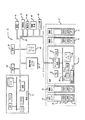
FIG. 1 is a schematic diagram of a patient care system using aspects of the present invention. In FIG. 1, a
患者ケア機器12は好ましくは、エガーズ他(Eggers et al. )に対する米国特許第5,713,856号で説明されているものと同様のシステムを有し、参照することによって本明細書に組み込まれる。また、本明細書で示した開示内容に従って、ポンプ、生理学的モニタ(例えば、心拍数、血圧、ECG、EEG、パルス酸素計、および他の患者モニタ)、治療機器、および他の薬物送出機器等の他の患者ケア機器を用いることもできる。患者ケア機器12は好ましくは、一つ以上の機能モジュール16,18,20,22に接続されたインタフェース・ユニット14とも呼ばれる制御モジュールを有する。インタフェース・ユニット14は、例えばランダム・アクセス・メモリ(RAM:Random Access Memory)58等のメモリに接続された中央演算処理ユニット(CPU:Central Processing Unit )50、およびユーザ・インタフェース機器54、符号化データ入力機器60、ネットワーク接続52、および別のモジュールまたは機器と通信するための補助インタフェース62等の一つ以上のインタフェース機器を含んでいる。インタフェース・ユニット14はさらに好ましくは、ソフトウェアおよびデータを格納するための不揮発性主記憶ユニット56、好ましくはハードディスク駆動装置、および上記の構成要素を相互接続するための一つ以上の内部バス64を有するが、必ずしも必須ではない。
典型的な実施形態では、ユーザ・インタフェース機器54は、ユーザに情報を表示し、画面の所定の領域を触れることによって、ユーザが情報を入力できるタッチ・スクリーンである。また、ユーザ・インタフェース機器54は、モニタ、プリンタ、キーボード、ソフトキー、マウス、トラック・ボールやライト・ペン等、情報を表示および入力するための任意の手段を含むことができる。符号化データ入力機器60は、好ましくはバーコード形式で印刷したデータを走査および解釈可能なバーコード・リーダである。また、データ入力機器60は、磁気ストリップ、PCMCIAスマート・カード、無線カード、メモリ・スティック、CD、DVD、または他の任意のアナログまたはデジタル記憶媒体を読み取る機器等、コンピュータに符号化データを入力する任意の機器であってもよい。データ入力機器60の他の例は、音声起動機器、音声認識機器または携帯型情報端末(PDA:Personal Data Assistant )を含んでいる。用いられるインタフェース機器の種類に応じて、ユーザ・インタフェース機器54と符号化データ入力機器60は、同じ機器であってもよい。また、データ入力機器60は図1ではインタフェース・ユニット14内に配置されるように示されているが、当業者には明らかなように、データ入力機器60は薬局システム34内に一体化することも、外部に配置し、RS−232シリアル・インタフェースまたは他の任意の適切な通信手段を介して、薬局システム34と通信することもできる。補助インタフェース62は好ましくはRS−232通信インタフェースであるが、発明の範囲から逸脱することなく、プリンタ、患者モニタ、輸液ポンプまたは他の医療機器等の周辺機器と通信するための他の任意の手段を用いることもできる。また、データ入力機器60は、モジュール16,18,20および22のような別個の機能モジュールであってもよく、適切なプログラムおよび通信プロトコルを用いて、制御部14またはネットワーク上の他の任意のシステムと通信するように構成される。
In an exemplary embodiment,
ネットワーク接続52は好ましくは、T1接続、統合サービスデジタル網(ISDN:Integrated Service Digital Network)接続、デジタル加入者線(DSL:Digital Subscriber Line )モデムまたはケーブル・モデム等の直接ネットワーク接続である。また、電話モデム、MIBシステム、RS−232インタフェース、補助インタフェース、光リンク、赤外線リンク、高周波リンク、マイクロ波リンク、WLANS接続または他の無線接続等を含む任意の直接または間接ネットワーク接続を用いることができるが、それらには限定されない。
機能モジュール16,18,20,22は、患者にケアを提供するか、あるいは患者の状態を監視する任意の機器である。図1に示したように、機能モジュール16,18,20,22のうちの少なくとも一つは、患者に薬物または他の流体を送出する静脈注射ポンプ等の輸液ポンプ・モジュールであってもよい。この説明のために、機能モジュール16は輸液ポンプ・モジュールとする。機能モジュール18,20,22は各々、輸液ポンプ、シリンジ・ポンプ、PCAポンプ、硬膜ポンプ、経腸ポンプ、血圧モニタ、パルス酸素計、EKGモニタ、EEGモニタ、心拍モニタ、頭蓋内圧モニタ等を含む任意の患者治療機器または監視機器であってもよいが、それらには限定されない。また、機能モジュール18,20,22は、プリンタ、スキャナ、バーコード・リーダまたは他の任意の周辺入力機器、出力機器または入出力機器であってもよい。
The
各機能モジュール16,18,20,22はインタフェース・ユニット14と直接または間接的に通信し、インタフェース・ユニット14は機器12を全体的に監視および制御する。機能モジュール16,18,20,22は、図1に示し、エガーズ他において詳しく説明されているように、インタフェース・ユニット14の一端または両端に、直列に物理的かつ電気的に接続されている。しかし、当業者には明らかなように、インタフェース・ユニットと機能モジュールを接続する他の手段も存在し、本発明の範囲から逸脱することなく用いることができる。当然のことながら、十分なプログラム可能性および接続を提供するポンプまたは患者監視機器等の機器は、スタンド・アロン機器として動作でき、別個のインタフェース・ユニットまたは制御ユニット14を介して接続することなく、ネットワークと直接通信できる。上記のように、一つ以上の補助インタフェース62を介して、患者ケア機器12に別の医療機器または周辺機器を接続することができる。
Each
各機能モジュール16,18,20,22は一般に、モジュール固有部品76、マイクロ・プロセッサ70、揮発性メモリ72および不揮発性メモリ74を有し、情報を格納する。当然のことながら、図1では四つの機能モジュールが示されているが、中央制御部14には任意の数の機器を直接または間接的に接続することができる。ここで説明した機能モジュールの種類および数は例示的なものとみなされ、決して本発明の範囲を限定するものではない。モジュール固有部品76は、輸液ポンプ16のポンプ機構等、特定のモジュールの動作に必要な任意の部品を含んでいる。
Each
各機能モジュールは一般に、少なくともいくつかのレベルの独立した動作を可能とするが、インタフェース・ユニット14は機器12の全体的な動作を監視し、制御する。例えば、以降でさらに詳しく説明するように、インタフェース・ユニット14は機能モジュール16,18,20,22にプログラム命令を提供し、各モジュールの状態を監視する。
Each functional module generally allows at least some levels of independent operation, but the interface unit 14 monitors and controls the overall operation of the
患者ケア機器12はいくつかの異なるモードまたは属性で動作可能であり、各属性は構成データベースで定義される。特定の構成データベースは、患者の場所、年齢、身体特性、または医療特性等の患者固有の情報に基づいて少なくとも部分的に選択される。医療特性は、患者の診断、治療処方、病歴、医療記録、患者ケア提供者識別番号、生理学的特性または心理学的特性等を含むが、それらには限定されない。ここで用いられるように、患者固有の情報はさらに、ケア提供者情報(例えば、医師識別番号)または病院内または病院コンピュータ・ネットワーク内での患者ケア機器10の位置を提供する。患者ケア情報は、インタフェース機器52,54,60または62を介して入力される。例えば、薬局34、受付36、実験室42等、ネットワーク10内の任意の場所からもたらされる。
The
様々なデータ源とやり取りするデータは既存の技術を用いて、ネットワーク互換データに変換され、医療機器とネットワークとの間の情報の移動は様々な手段によって実現される。例えば、患者ケア機器12とネットワーク10とは、自動インタラクション、手動インタラクションまたは自動および手動のインタラクションの両方の組合せによって通信される。自動インタラクションは連続的または断続的であってもよく、直接ネットワーク接続54(図1に示したように)を介して、またはRS232リンク、MIBシステム、ブルートゥース(カリフォルニア州サンノゼ、Amtel社)、IRリンク、WLANS、デジタル・ケーブル・システム、電話モデムまたは他の有線または無線通信手段を介して発生させてもよい。患者ケア機器12とネットワーク10との間の手動インタラクションは、例えば、ユーザ・インタフェース機器54、符号化データ入力機器60、バーコード、コンピュータ・ディスク、携帯型情報端末、メモリ・カード、またはデータを格納する他の任意の媒体を用いて、システム間でデータを間欠的または周期的、物理的に転送することを含んでいる。好ましくは、通信手段は、分散されたデータ源のできるだけ多くの点からデータに双方向にアクセスする。意志決定は、ネットワーク10内の様々な場所で発生する。例えば、病院情報システム・サーバ30、判断支援48、リモート・データ・サーバ49、病院部局またはユニット局46、または患者ケア機器12のそれ自体内で意志決定を行うことができるが、それらには限定されない。
Data exchanged with various data sources is converted into network compatible data using existing technology, and movement of information between the medical device and the network is realized by various means. For example, the
本発明の態様を組み込んだクライアント/サーバ環境は一般に、コンピュータ・ネットワークを介して、少なくとも一つのクライアントがアクセス可能な中央サーバを含んでいる。より複雑なシステムでは、中央サーバは、例えば、イーサネット(登録商標)、無線ネットワーク、またはインターネット等のコンピュータ・ネットワークを介して、少なくとも一つのローカル・サーバによってアクセスされ、次にローカル・サーバがクライアントによってアクセスされる。TCP/IPを含むがそれには限定されない様々なコンピュータ・ネットワーク転送プロトコルは、ネットワーク上で用いられる通信プロトコルと互換性のある通信機能を備えるように構成された中央サーバ、任意のローカル・サーバ、およびクライアント機器の間での通信を可能にするために用いられる。 A client / server environment incorporating aspects of the present invention typically includes a central server accessible by at least one client over a computer network. In more complex systems, the central server is accessed by at least one local server via a computer network such as, for example, Ethernet, wireless network, or the Internet, and then the local server is accessed by the client. Accessed. Various computer network transport protocols, including but not limited to TCP / IP, include a central server, any local server, and any local server configured to have communication capabilities compatible with the communication protocols used on the network, and Used to enable communication between client devices.
中央サーバは一般に、その上で実行するMicrosoft(登録商標) SQL Severアプリケーション・プログラム・バージョン6.5(ワシントン州レドモンド、Microsoft,Inc.から入手可能)等の中央データベースを含んでいる。中央サーバは、ローカル・サーバが最新バージョンの知識ベースを実行していることを保証し、さらに全ての患者データを格納し、システムにローカル・サーバおよびユーザを追加および削除することを含む様々な管理機能を行うことができる。中央サーバはさらに、ユーザがローカル・サーバまたはクライアント医療機器を利用可能になる前に許可を行う。上記のように、一般的な統合型システムでは、患者データは好ましくは中央サーバに格納され、それによって患者データの中央レポジトリを提供する。しかし、当然のことながら、患者データは、ローカル・サーバ、ローカル記憶媒体、または別の病院または施設のサーバや情報システム上に格納でき、必要に応じて、システムの様々な要素、つまりローカル・サーバやクライアントを介してアクセスすることができる。 The central server typically includes a central database, such as Microsoft® SQL Server application program version 6.5 (available from Microsoft, Inc., Redmond, WA) running on it. The central server ensures that the local server is running the latest version of the knowledge base, stores all patient data, and includes various controls including adding and deleting local servers and users to the system The function can be performed. The central server further provides authorization before the user can use the local server or client medical device. As mentioned above, in a typical integrated system, patient data is preferably stored on a central server, thereby providing a central repository of patient data. However, it will be appreciated that patient data can be stored on a local server, a local storage medium, or another hospital or facility server or information system, depending on the various elements of the system, ie the local server. And can be accessed through the client.
各ローカル・サーバは一般に、地理的位置における複数のユーザにサービスを提供する。各ローカル・サーバの例は、病棟内、看護婦室、または主情報またはバックアップ情報の収集、経路指定、解析や記憶システムとして動作する現場外または離れた場所に配置したサーバを含んでいる。各ローカル・サーバは一般に、サーバ・アプリケーション、一つ以上の知識ベース、およびローカル・データベースを有する。各ローカル・サーバはさらに、適切な医療や薬物送出および処方診療に従うことを保証する一連の規則または診療基準とやり取り可能な推論システムを含むこともできる。各ローカル・サーバはさらに、本発明の動作を実行する人工知能処理を行うこともできる。ユーザがクライアントを介してログオンすると、当業者には明らかなように、好ましくは識別番号およびパスワードを介して認証される。一旦認証されると、ユーザはシステムへのアクセスが許可され、特定の管理特権が割り当てられる。また、システムの動作をプログラムし、バーコード・ラベル、RF識別タグまたは機器、または他のスマート、受動型、能動型識別機器等の、患者、ケア提供者および薬物識別機器を用いて、システムのユーザを識別し、患者を診断および治療するシステムにアクセスできるようにする。 Each local server typically serves multiple users at a geographical location. Examples of each local server include a server located in a ward, nurse room, or off-site or remotely that acts as a collection, routing, analysis or storage system for main or backup information. Each local server typically has a server application, one or more knowledge bases, and a local database. Each local server may further include an inference system that can interact with a set of rules or clinical criteria that ensure compliance with appropriate medical and drug delivery and prescription practice. Each local server can also perform artificial intelligence processing that performs the operations of the present invention. When a user logs on via a client, it is preferably authenticated via an identification number and password, as will be apparent to those skilled in the art. Once authenticated, the user is granted access to the system and is assigned certain administrative privileges. It also programs the operation of the system and uses patient, care provider and drug identification devices such as barcode labels, RF identification tags or devices, or other smart, passive, active identification devices, etc. Identify users and gain access to systems for diagnosing and treating patients.
各ローカル・サーバはさらに中央サーバと通信を行い、要求中のローカル・サーバ上で最新版の知識ベースおよびアプリケーションが実行中であることを確認することもできる。最新版でない場合は、要求中のローカル・サーバは、ユーザ・セッションが確立される前に、正当な最新の知識ベースやアプリケーションを中央サーバからダウンロードする。本発明のいくつかの実施形態では、データおよび人工知能処理等、最も計算上集約的作業をローカル・サーバ上で実行するが、「小型軽量クライアント」、つまり最小のハードウェアおよび最適システム速度を備えた計算機器も可能であり、本発明はさらにクライアント上でデータ処理および規則処理を実行し、このようなタスクから中央システム、またはローカル・サーバを解放するシステムを含むものとする。 Each local server can also communicate with the central server to verify that the latest knowledge base and application are running on the requesting local server. If not, the requesting local server downloads a valid current knowledge base or application from the central server before the user session is established. In some embodiments of the present invention, the most computationally intensive work, such as data and artificial intelligence processing, is performed on the local server, but with a “thin client”, ie, minimal hardware and optimal system speed. Computing devices are also possible, and the present invention further includes systems that perform data processing and rule processing on the client and free the central system or local server from such tasks.
各ローカル・クライアントまたは医療機器はさらに、一般にグラフィカル・ユーザ・インタフェース(GUI:Graphical User Interface)からなるクライアント・アプリケーション・プログラムを含んでいるが、このようなものは多くの医療機器、および中央サーバまたはローカル・サーバと通信する中間層プログラム上では不要である。クライアント・アプリケーション・プログラム用のプログラム・コードは全体的にローカル・クライアント上で実行可能であり、部分的にローカル・クライアント上で実行し、部分的に中央またはローカル・サーバ上で実行することもできる。 Each local client or medical device further includes a client application program, typically consisting of a graphical user interface (GUI), such as many medical devices and a central server or It is not necessary on the middle-tier program that communicates with the local server. Program code for client application programs can be executed entirely on the local client, partly on the local client, and partly on the central or local server .
本発明の動作を実行するコンピュータ・プログラム・コードは好ましくは、例えばJAVA(登録商標)、スモールトーク、またはC++等のオブジェクト指向プログラム言語で作成される。しかし、本発明の動作を実行するコンピュータ・プログラム・コードは、Cプログラム言語等の既存の手続き型プログラム言語、Perl等のインタプリタ型スクリプト言語、Lisp、SML、Forth等の関数型(または第四世代)プログラム言語で作成することもできる。ソフトウェアはさらに、HLA−7要件に適合するように作成することもできる。 The computer program code that performs the operations of the present invention is preferably written in an object oriented programming language such as JAVA®, small talk, or C ++. However, the computer program code for executing the operation of the present invention is an existing procedural program language such as C program language, an interpreted script language such as Perl, or a functional type such as Lisp, SML, or Forth (or fourth generation). ) Can be created in programming language. The software can also be written to meet HLA-7 requirements.
次に、本発明の典型的な実施形態について説明する。一般に、本発明の態様を組み込んだ医療機器はネットワーク・インタフェース・モジュール(NIM:Network Interface Module)を備え、医療機器はネットワーク内のノードとして参加できる。簡略化のために、本発明はインターネット・プロトコル(IP:Internet Protocol )を用いて、イーサネット・ネットワーク環境で動作するものとして説明されるが、当業者には明らかなように、本発明の概念は同様に他のネットワーク環境に適用することもでき、このような環境は本発明の範囲内にあるものとする。 Next, exemplary embodiments of the present invention will be described. In general, a medical device incorporating aspects of the present invention comprises a network interface module (NIM), and the medical device can participate as a node in the network. For simplicity, the present invention is described as operating in an Ethernet network environment using the Internet Protocol (IP), but as will be apparent to those skilled in the art, the concept of the present invention is Similarly, it can be applied to other network environments, and such environments are within the scope of the present invention.
本発明に従ってネットワーク上で動作する医療機器との直接通信は全て、リモート・データ・サーバ(RDS:Remote Data Server)と呼ばれる中央サーバを介して実行される。本発明の態様によると、例えば輸液ポンプまたは生存徴候測定機器等の医療機器に組み込んだネットワーク・インタフェース・モジュールは、認証済みのRDSに起因しない全てのネットワーク・トラフィックを無視する。本発明のRDSの主な責任は、NIMを備え、ネットワーク上の全ての医療機器の場所と状態を追跡し、それらとの通信チャネルを開いたままで維持することである。 All direct communication with medical devices operating on a network according to the present invention is performed through a central server called a remote data server (RDS). In accordance with aspects of the present invention, a network interface module incorporated into a medical device, such as an infusion pump or vital sign measurement device, ignores all network traffic that is not attributed to an authenticated RDS. The main responsibility of the RDS of the present invention is to provide a NIM, track the location and status of all medical devices on the network, and keep the communication channel open with them.
本発明の典型的な実施形態では、RDSがネットワーク上の医療機器を発見、接続する。それと通信する手段を含むソフトウェアおよび通信プロトコルのアーキテクチャは例えば、イーサネットLAN環境内で動作する。LAN上の任意の二つのノードの間のデータの名目上のラウンド・トリップ・タイムは一般に1秒未満であり、ネットワーク上の各リンクは一般に少なくとも1Mbpsの維持速度でデータを送信できる。全ネットワーク帯域幅の10%以下が所定の時間に利用可能であれば、典型的なネットワークは効率的に稼働中であるとみなされるが、当然のことながら、無線ネットワーク環境で発生するように、ノードは間欠的ネットワーク接続を被ることがあり、このような接続の中断は重要性および持続時間の両方で大きく変化する。 In an exemplary embodiment of the invention, RDS discovers and connects medical devices on the network. Software and communication protocol architecture, including means for communicating with it, operates, for example, in an Ethernet LAN environment. The nominal round trip time of data between any two nodes on the LAN is typically less than 1 second, and each link on the network can typically transmit data at a maintenance rate of at least 1 Mbps. If less than 10% of the total network bandwidth is available at a given time, a typical network is considered to be operating efficiently, but it should be understood that as occurs in a wireless network environment, Nodes can suffer intermittent network connections, and such interruptions can vary greatly in both importance and duration.
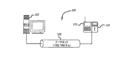
図2は、本発明を最も簡単な実施形態で示している。この実施形態では、本発明の原理によるシステムは単一のリモート・データ・サーバ105と、例えば、イーサネット・ケーブル120等の適切な通信手段を介して、共に接続されたネットワーク・インタフェース・モジュール115に取り付けた単一の医療機器110からなる。RDS105とNIM115との間の接続はイーサネット・ケーブル120によって示されているが、当業者には明らかなように、有線または無線の任意の手段を用いて、RDS105とNIM115とを互いに通信するように配置し、それらの間に情報の流れを提供する。
FIG. 2 illustrates the invention in its simplest embodiment. In this embodiment, a system according to the principles of the present invention is connected to a single
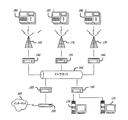
本発明の態様に従って動作するより複雑なシステムが、図3に示されている。この実施形態では、システムは主RDS130と、ルータ140を介してイーサネット145に接続されたバックアップRDS135を有する。イーサネット145を介して、RDS130,135で通信される情報は、ルータ150,155,160および送受信無線アクセス・ポイント165,170,175を介して、医療機器180,185,190に通信される。上記のように、医療機器180,185および190はネットワーク・インタフェース・モジュールを有し、前記ネットワーク・インタフェース・モジュールは無線アクセス・ポイント165,170および175と情報を無線送受信するための適切な回路を含んでいる。当然のことながら、ネットワークの大きさおよび複雑さは、図3に示したものに限定されない。ただし、ネットワークの大きさや複雑さは、発見と接続に用いられるプロトコルに依存しない。
A more complex system that operates in accordance with aspects of the present invention is shown in FIG. In this embodiment, the system has a
さらに、情報は、ルータ195およびファイアウォールまたはインターネット・プロキシ200を介して、インターネットまたはイントラネット205等の別のシステムとやり取りされる。この方法では、第三者のシステムまたは機器は、医療機器180,185,190と通信できる。さらに以降で詳しく説明するように、本発明のシステムのアーキテクチャおよび動作は、ネットワーク内の情報の安全な流れを提供する。第三者の機器(図示せず)がネットワーク上の医療機器180,185,190との通信を希望すると、イーサネット145を介して、RDS130または135等の起動中のRDSにそれらの要求を送信することによって通信を行う。それから、RDSは、可能であれば、第三者の機器の代わりに、ネットワーク上の医療機器に要求を行う。第三者の機器は、そのNIMを介して、ネットワーク上の医療機器と直接通信を開始することは決してない。この方法では、外部の第三者の機器はネットワーク上の医療機器との通信を起動できないので、通信セッションのセキュリティが保証される。RDSを介して開始しない第三者の要求は全て無視される。
In addition, information is exchanged with another system, such as the Internet or
アドレス指定
本発明の好ましい実施形態では、システムの接続プロトコルはIP/イーサネット上で動作する。この実施形態では、システム内の各NIMには、通信を可能にするために一意的なIPアドレスが割り当てられる。IPアドレスを静的に割り当てることもできるし、ユーザは動的アドレス割り当てのためにDHCPを用いることを選択することもできる。両方の方法が、NIMによってサポートされている。
Addressing In the preferred embodiment of the present invention, the connection protocol of the system operates over IP / Ethernet. In this embodiment, each NIM in the system is assigned a unique IP address to enable communication. The IP address can be assigned statically or the user can choose to use DHCP for dynamic address assignment. Both methods are supported by NIM.
冗長的サーバ
医療機器180,185および190との通信は全てRDSを介して経路指定されるので、RDSがシステム内の最も重要な障害点となる。耐障害性を増強したいエンド・ユーザは、主RDS130とバックアップRDS135によって図3に例示したように、そのネットワーク上に一つ以上の冗長的RDSをセットアップすることを選択できる。このような冗長性は本発明の接続プロトコルによって十分にサポートされ、冗長的サーバは一般に能動型/受動型構成でセットアップされる。
Redundant Server Since all communications with
冗長的クラスタ内のRDS135等のバックアップ・リモート・データ・サーバをネットワークに直接接続し、一意的なIPアドレスを割り当てることも、従来から知られているように、変換ルータ(図示せず)を介して接続し、全てが同じIPアドレスを有するようにすることもできる。本発明を組み込んだ動作システムの接続プロトコルは、両方の構成をサポートしている。 It is also possible to connect a backup remote data server such as RDS135 in a redundant cluster directly to the network and assign a unique IP address via a translation router (not shown) as is conventionally known. Can be connected so that all have the same IP address. The operating system connection protocol incorporating the present invention supports both configurations.
負荷バランシング
複数のサブネットが存在する非常に大きなネットワークでは、冗長的クラスタを用いてサブネットを論理的グループに分割し、別個のリモート・データ・サーバを各グループに割り当てることによって、負荷バランシングを行うことができる。このようなシステム上の唯一の制限は、一つ以上のRDSが単一のサブネットにサービスを提供できないことである。RDSとNIMとの間の接続のセキュリティを保証するために、そのローカル・サブネット上に動作中のRDSを一つ以上検出した場合、NIMは一般にRDSへの応答を拒絶するようにプログラムされる。
Load balancing In very large networks with multiple subnets, load balancing can be achieved by using redundant clusters to divide the subnets into logical groups and assign separate remote data servers to each group. it can. The only limitation on such a system is that one or more RDS cannot service a single subnet. In order to ensure the security of the connection between the RDS and the NIM, the NIM is typically programmed to reject a response to the RDS if it detects one or more active RDSs on its local subnet.
図3に示したように、ネットワーク、ここではイーサネットは、医療機器と主RDSおよびバックアップRDSとの間の情報の通路として機能する。イーサネットはさらに、ファイアウォールやインターネット・プロキシを介してインターネットに接続される。一般に、インターネット・アクセスおよびRDSサーバ管理はどちらも、適切なルータを介してイーサネットと通信する。図のように、複数の医療機器をイーサネットに接続し、それからRDSと通信することもできる。図3に示したように、医療機器は、無線アクセス・ポイントに信号を提供する適切なルータを介してイーサネットと通信する。医療機器は同報通信の信号を受信し、さらに無線アクセス・ポイント上に信号を送信し、それから所望の宛先までイーサネット上で通信できる。また、医療機器はイーサネットに有線接続し、無線アクセス・ポイントを不要にすることもできる。さらに別の方法では、ルータと無線アクセス・ポイントを単一ユニットに組み合わせることもできる。 As shown in FIG. 3, the network, here Ethernet, serves as a path of information between the medical device and the main RDS and backup RDS. The Ethernet is further connected to the Internet through a firewall or Internet proxy. In general, both Internet access and RDS server management communicate with Ethernet via a suitable router. As shown, multiple medical devices can be connected to the Ethernet and then communicate with the RDS. As shown in FIG. 3, the medical device communicates with the Ethernet via a suitable router that provides signals to the wireless access point. The medical device can receive the broadcast signal, send the signal over a wireless access point, and then communicate over Ethernet to the desired destination. Medical devices can also be wired to Ethernet, eliminating the need for wireless access points. In yet another approach, the router and wireless access point can be combined into a single unit.
ソフトウェア・アーキテクチャ
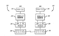
図4は、本発明のソフトウェア・アーキテクチャの典型的な実施形態を示している。図4に示したように、RDS250およびNIM255上のソフトウェア・スタックは同じように見えるが、以降で説明するように、アプリケーション層260,280で実行するソフトウェアはかなり異なり、RDS250およびNIM255の異なる機能を反映させることができる。RDS250の発見および接続管理プロトコル層275と、NIM255の発見および接続管理プロトコル層290は、アプリケーション・レベル275,295と接続レベル265,290との間のRDSおよびNIMシステム上のソフトウェア・スタックに適合する。NIM255上では、動作プログラムの発見および接続管理層290は、正当なRDS250を備えたNIM255に接続された医療機器の配置および登録する役割を担う。RDS250上では、発見および接続管理層270は、全ての動作中のNIM255のリストを維持する役割を担う。RDS250およびNIM255のどちらの側も互いの間のTCP/IP接続を維持し、各アプリケーション層275,295の代わりに、それらの接続上でデータを送受信する役割を担う。
Software Architecture FIG. 4 illustrates an exemplary embodiment of the software architecture of the present invention. As shown in FIG. 4, the software stack on
発見および接続管理層270,290の各々の下のRDS250の層265,260およびNIM255の285,280は標準的なTCP/IPスタックを表しており、その用語は当業者には明らかであり、RDS250およびNIM255の両方で一般に同じである。アプリケーション層275,295は、接続層270,290のインタフェースとなる任意の高レベル・ソフトウェア・プログラム・コードを含んでいる。
発見
RDS250とNIM255に接続されたた機器との間で通信が発生可能になる前に、二つのシステムは互いにネットワーク上に位置し、接続を確立しなければならない。この処理は、この説明のために発見と呼ばれる。
Discovery Before communication can occur between a device connected to the
RDSビーコン
本発明のシステムおよび方法を組み込んだRDS250が、NIM255に接続された医療機器と通信を開始し、サービスを提供することを準備する際、RDS250はネットワーク全体に特別な「ビーコン・メッセージ」の送信を開始する。このビーコンの目的は、様々な医療機器に接続されたNIM255に対して、ネットワーク上にRDS250が存在することを警告することにある。ビーコンは、ネットワーク上のUDP同報通信を介して、RDS250がサービスを提供する各サブネット上の既知のポートに送信される。前記ネットワークはイーサネットであっても、無線ネットワークであってもよい。NIM255は、通信するRDS250の位置の発見を開始する際、このビーコンをリスニングするようにプログラムされている。また、NIM255は、ビーコン信号またはメッセージを周期的に検索するようにプログラムされていてもよい。この実施形態では、この周期的にビーコンをリスニングすることは、通信リンクが何らかの理由で消失した場合に、RDS250との接続を再確立するのに役立つ。
RDS Beacons When an
この好ましい実施形態では、本発明によるRDSビーコン信号またはメッセージは一般に、サービスを提供するサブネット上に一定の間隔(一般に1秒)で同報通信される。一般に、RDS250はオフラインになるまで、永久にビーコン・メッセージを同報通信する。一旦接続すると、ネットワークに接続された各医療機器のNIM255は(様々な理由で)ビーコンをリスニングし続け、所定の期間内にビーコンを受信しなければ、RDS250との接続を終了するので、RDS250はビーコン・メッセージを同報通信し続ける。
In this preferred embodiment, RDS beacon signals or messages according to the present invention are generally broadcast at regular intervals (generally 1 second) over the serving subnet. In general,
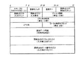
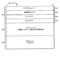
図5は、RDSビーコン・メッセージの一実施形態のデータ形式を示している。メッセージは複数のフィールドからなり、特定のフィールドに依存して異なるデータ長を備えている。好ましくは、1バイトより長いデータ・フィールドが全てリトルエンディアン形式で格納され、この実施形態のビーコン・メッセージの全サイズは決して512バイトを超えないが、これより大きな有効ビーコン・メッセージを構成することもでき、このようなメッセージも本発明の範囲内にあるものとする。暗号化の追加層を適用して、さらにセキュリティを改善して送信することもできる。ビーコン・メッセージの各フィールドについては、以降で詳しく説明する。 FIG. 5 illustrates the data format of one embodiment of the RDS beacon message. The message consists of a plurality of fields, and has a different data length depending on a specific field. Preferably, all data fields longer than 1 byte are stored in little endian format, and the total size of the beacon message in this embodiment never exceeds 512 bytes, but may constitute a larger valid beacon message. Such messages are also within the scope of the present invention. An additional layer of encryption can be applied to further improve security and transmit. Each field of the beacon message will be described in detail later.
メッセージID
ビーコン・メッセージの第一バイトは、メッセージIDである。このバイトは一定であり、RDSビーコンとしてメッセージを識別するために用いられる。
Message ID
The first byte of the beacon message is a message ID. This byte is constant and is used to identify the message as an RDS beacon.
登録モジュロおよびキー
特定の種類のグローバル・ネットワーク障害(例えば、ルータの再起動等)は、動作中のRDS/NIMネットワーク内の通信を一時的に遮断することがある。このような遮断の影響は、影響を受けた各NIMがRDSとの接続を遮断し、RDSに再登録しようとすることである。このような中断の後、一旦接続が回復すると、潜在的に数千の同時の登録要求によってRDSは過負荷になることがある。従って、ビーコン・メッセージは絞り機構を有し、このような状態でのRDS上の負荷を低減する。
Registration Modulo and Key Certain types of global network failures (eg, router restarts, etc.) may temporarily block communications within an active RDS / NIM network. The effect of such blocking is that each affected NIM blocks the connection with the RDS and tries to re-register with the RDS. Once the connection is restored after such an interruption, the RDS can potentially be overloaded with thousands of simultaneous registration requests. Therefore, the beacon message has a throttling mechanism to reduce the load on the RDS in such a situation.
本発明の一実施形態において、図5を再び参照すると、NIMがRDSから正当なビーコン・メッセージを受信すると、NIMはビーコン・メッセージの登録モジュロ・フィールド内に含まれるデータを用いて、そのIPアドレスのモジュロを計算する。結果がビーコン・メッセージの登録キー・フィールド内に格納された値と等しい場合、このような応答が正当であれば、NIMはRDSに単一の発見応答メッセージを送信することを許可される。NIMのIPアドレスのモジュロがビーコン・メッセージの登録キー・フィールドと一致しない場合、NIMは沈黙したままで、応答するまで次のビーコンを待機する。一般的な好ましい実施形態では、ビーコン・メッセージの登録モジュロ・メッセージ内に格納される値は決して2未満にはならず、登録キー・フィールドに格納される値は常に登録モジュロ・フィールド内に格納される値より小さい。当業者には明らかなように、計算の基本としてIPアドレスを用いる必要はなく、意図した発明の範囲から逸脱することなく、機器の一意的な任意の値を用いることができる。 In one embodiment of the present invention, referring again to FIG. 5, when the NIM receives a valid beacon message from the RDS, the NIM uses its data contained in the registration modulo field of the beacon message to determine its IP address. Calculate the modulo of. If the result is equal to the value stored in the registration key field of the beacon message, if such a response is valid, the NIM is allowed to send a single discovery response message to the RDS. If the modulo of the NIM's IP address does not match the registration key field of the beacon message, the NIM remains silent and waits for the next beacon until it responds. In a general preferred embodiment, the value stored in the registration modulo message of the beacon message is never less than 2, and the value stored in the registration key field is always stored in the registration modulo field. Is less than As will be apparent to those skilled in the art, it is not necessary to use an IP address as the basis for the calculation, and any unique value of the device can be used without departing from the intended scope of the invention.
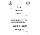
閉終点リスト
NIMとのネットワーク接続が消失すると、RDSはNIMとのTCP/IP接続をタイムアウトにすることによって、NIMとの通信セッションを終わらせるようにプログラムされている。このことが発生すると、TCP/IP接続を打ち切って閉じ、閉じたTCP/IP接続のIPアドレスとポート番号の形態で、ビーコン・メッセージ内に閉じたことについての通知を配置する。本発明の一実施形態では、閉通知を有する三つの固定サイズ・フィールドと二つの可変長フィールドという五つの別個のフィールドがあり、これ以降は閉終点データと呼ぶ。
Closed Endpoint List When the network connection with the NIM is lost, the RDS is programmed to terminate the communication session with the NIM by timing out the TCP / IP connection with the NIM. When this occurs, the TCP / IP connection is aborted and closed, and a notification about the closure is placed in the beacon message in the form of the IP address and port number of the closed TCP / IP connection. In one embodiment of the present invention, there are five separate fields, three fixed size fields with a close notification and two variable length fields, hereinafter referred to as closed endpoint data.
閉終点データの第一固定長フィールドは、閉終点リスト開始オフセット・フィールドである。このフィールドは、閉終点リストを発見できるビーコン・メッセージ内のオフセット(バイト単位)を有する。このオフセットは、ビーコン・メッセージの最初から開始される。 The first fixed length field of the closed end point data is a closed end point list start offset field. This field has an offset (in bytes) within the beacon message where the closed endpoint list can be found. This offset starts from the beginning of the beacon message.
閉終点データの次の固定長フィールドは、閉終点リスト入力カウント・フィールドである。このフィールドは、ビーコン・メッセージの終わりで、可変長のIPアドレスおよびポート番号のフィールド内に列挙される閉終点数を有する。 The next fixed length field of the closed end point data is the closed end point list input count field. This field has a closed endpoint number listed in the variable length IP address and port number fields at the end of the beacon message.
閉終点データの第三固定長フィールドは、閉終点リスト入力寿命フィールドである。このフィールドは、各閉終点が列挙される連続したビーコン・メッセージの数を有する。例えば、この値が5であり、TCP/IP接続がRDSによって閉じられた場合、次の利用可能なビーコン・メッセージ内に閉終点データを配置し、それから次の4ビーコン・メッセージの間、繰り返す。閉終点リスト入力寿命フィールドの値は、決して1未満にはならない。 The third fixed length field of the closed end point data is a closed end point list input life field. This field has a number of consecutive beacon messages in which each closed endpoint is listed. For example, if this value is 5 and the TCP / IP connection is closed by RDS, place the closing endpoint data in the next available beacon message and then repeat for the next 4 beacon messages. The value of the closed endpoint list input life field will never be less than one.
図5に示したように、閉終点用の実際のデータは、ビーコン・メッセージの終わりで可変長フィールド内に格納される。閉終点データは、閉じられたTCP/IP接続のIPアドレスおよびポート番号からなる。これらの値は各々4バイトおよび2バイトの長さであるので、共にメッセージ内に配置されると位置あわせの問題が発生し得る。フィールド長を適合させるためのデータを埋め込む時間および空間の無駄を避けるために、IPアドレスおよびポート番号はそれら自体のリスト内に別個に格納される。これらのリストは、その要素が互いに対応する、つまり、各リストのステップを踏む際、第一IPアドレスは第一ポートと同期させ、第二アドレスは第二ポートと同期させる等というように構成される。これは、IPアドレスおよびポート番号の数が常に等しいことを意味するが、いくつかの実施形態ではIPアドレスおよびポート番号の数が異なることも可能であるが、適切な埋め込みまたは既定値の空白は避けなければならない。 As shown in FIG. 5, the actual data for the closed endpoint is stored in a variable length field at the end of the beacon message. The closed end point data consists of the IP address and port number of the closed TCP / IP connection. Since these values are each 4 bytes and 2 bytes long, alignment problems can occur when both are placed in the message. In order to avoid wasting time and space for embedding data to adapt field lengths, IP addresses and port numbers are stored separately in their own lists. These lists are structured such that the elements correspond to each other, that is, when taking the steps of each list, the first IP address is synchronized with the first port, the second address is synchronized with the second port, etc. The This means that the number of IP addresses and port numbers is always equal, although in some embodiments the number of IP addresses and port numbers can be different, but proper padding or default blanks are Must be avoided.
ビーコン間隔
図5を再び参照すると、閉終点リストの第二可変長フィールドは、ビーコン間隔フィールドである。このフィールドは、RDSがどの程度の頻度でビーコン・メッセージのパケットを送信するかを示す値を有する。一般に、この値はミリ秒単位で表され、その値が1000(1秒)以上である場合に、プログラムが最も効率的になることを発明者は見出しているが、値が1000未満であっても処理は許容可能なように機能するが、資源管理およびデータ・フローの点では効率的ではない。
Beacon interval Referring again to FIG. 5, the second variable length field of the closed endpoint list is the beacon interval field. This field has a value that indicates how often the RDS transmits a packet of beacon messages. In general, this value is expressed in milliseconds, and when the value is 1000 (1 second) or more, the inventor has found that the program is most efficient, but the value is less than 1000. Although the process functions as acceptable, it is not efficient in terms of resource management and data flow.
時間
図5に示した三つのタイムスタンプ・フィールドは、RDSからの現在の時間および日付を含んでいる。この情報は、必要であれば、リモート機器のクロックとRDSのクロックとを同期化させるために用いることができる。一般に、この実施形態では、国際化や夏時間調整等の問題を避けるために、UTC時刻で提供される。しかし、システム全体がUTC時刻以外の標準時に従って動作中である場合、ネットワークの全ての機器に適合する限り、適切な標準時を用いることができる。
Time The three timestamp fields shown in FIG. 5 contain the current time and date from the RDS. This information can be used to synchronize the remote device clock and the RDS clock, if necessary. Generally, in this embodiment, it is provided in UTC time to avoid problems such as internationalization and daylight savings. However, if the entire system is operating according to a standard time other than UTC time, an appropriate standard time can be used as long as it is compatible with all devices in the network.
本発明の一実施形態では、第一タイムスタンプ・フィールド、つまりUTC年の時刻フィールドは、現在の年の1月1日の午前12:00から経過する時間を数百秒有し、第二タイムスタンプ・フィールド、つまりUTC年フィールドは現在のUTC暦年を有する。ローカル時刻オフセット・フィールド、つまり第三タイムスタンプ・フィールドは、ローカル時刻とUTC時刻の間の違いを一般に分単位で表す符号付きの値を有する。 In one embodiment of the present invention, the first time stamp field, the UTC year time field, has a time of several hundred seconds since 12:00 am on January 1 of the current year, and the second time The stamp field, or UTC year field, has the current UTC calendar year. The local time offset field, or third time stamp field, has a signed value that generally represents the difference between local time and UTC time in minutes.
将来的なデータ
図5に示したRDSメッセージ・ビーコンの領域は、「追加データ可能(将来的な改訂)」というラベルを付けて、将来的に固定サイズのフィールドをビーコン・メッセージに追加可能な空間を提供し、ビーコン・メッセージの増強または拡張を可能にする。閉終点データ・フィールドは可変長であり、ビーコン・メッセージの構文解析を行い、他の固定サイズ・フィールドにアクセスして、容易に計算を実現するために、メッセージの終わりに配置することが最善であるので、この方法でメッセージ・ビーコンを将来変更できるようにすることが望ましい。一般に、ネットワーク上の全てのNIMまたは選択されたNIMに生成されたソフトウェアの改訂等、特にプログラムされない限り、NIM上で実行中のソフトウェアは余分なデータを想定し、そのデータを無視する。
Future Data The area of the RDS message beacon shown in FIG. 5 is labeled as “additional data available (future revision)” and space where a fixed size field can be added to the beacon message in the future. To enable augmentation or expansion of beacon messages. The closed endpoint data field is variable length and is best placed at the end of the message to parse the beacon message and access other fixed size fields for easy computation. As such, it is desirable to be able to change the message beacon in the future in this way. In general, unless specifically programmed, such as a revision of all NIMs on a network or software generated on a selected NIM, software running on the NIM assumes extra data and ignores that data.
NIM状態応答
本発明の好ましい一実施形態では、NIMは常にメッセージの入力に対して選択されたUDPポート上をリスニングし、正当なRDSビーコン・メッセージであるか否かを確認するために、受信した各メッセージをチェックする。受信したメッセージが正当なRDSビーコン・メッセージであり、以降でさらに詳しく説明する特定の条件に適合する場合、NIMはビーコン・メッセージを発信したRDSサーバ上のUDPポートにNIM状態応答メッセージを送り返すことによって、RDSビーコンに応答する。
NIM Status Response In a preferred embodiment of the present invention, the NIM always listens on the selected UDP port for message input and receives to verify if it is a legitimate RDS beacon message. Check each message. If the received message is a legitimate RDS beacon message and meets certain conditions described in more detail below, the NIM sends a NIM status response message back to the UDP port on the RDS server that originated the beacon message. In response to the RDS beacon.
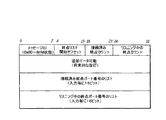
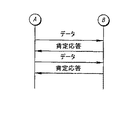
図6は、NIM状態応答メッセージの一実施形態のデータ形式を示している。ビーコン・メッセージと同様に、1バイトより大きな長さを備えた全てのデータ・フィールドは一般に、リトルエンディアン形式で格納される。一実施形態では、NIM状態応答メッセージの全サイズは一般に512バイトを超えないが、512バイトを超える正当な状態応答メッセージを構成することもでき、このようなメッセージは本発明の範囲内にある。また、上記のRDSビーコン・メッセージと同様に、状態応答メッセージに追加の暗号層を適用し、メッセージのセキュリティを拡張して送信することもできる。NIM状態応答メッセージの各フィールドについては、以降で詳しく説明する。 FIG. 6 illustrates the data format of one embodiment of the NIM status response message. Similar to beacon messages, all data fields with a length greater than 1 byte are generally stored in little endian format. In one embodiment, the overall size of the NIM status response message generally does not exceed 512 bytes, but a legitimate status response message that exceeds 512 bytes may be constructed, and such messages are within the scope of the present invention. Similarly to the RDS beacon message described above, an additional encryption layer can be applied to the status response message to transmit the message with enhanced security. Each field of the NIM status response message will be described in detail later.
メッセージID
図6に示したように、状態応答メッセージの第一バイトはメッセージIDフィールドである。このバイトは一定であり、NIM状態応答メッセージとしてメッセージを識別するために用いられる。
Message ID
As shown in FIG. 6, the first byte of the status response message is a message ID field. This byte is constant and is used to identify the message as a NIM status response message.
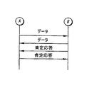
接続済み/リスニング中終点リスト
図6に示した状態応答メッセージの実施形態の次のフィールドは、終点リスト開始オフセット・フィールドである。一般に、NIMは、例えば、USBハブ等を介して、直ちにいくつかのクライアント機器に接続を提供できるようにプログラムされている。RDSからのアプリケーション・レベル・メッセージを処理可能なNIMに取り付けた各機器は終点とみなされ、NIMによるRDSへのそれ自体の専用TCP/IP接続を与えられる。NIMが状態応答メッセージを送信したとき、それはRDSが接続を生成可能なTCP/IPポートのリストの形式で、利用可能な各終点のリストを有する。このリストは、現在RDSに正当な接続を有するポート、およびRDSへの新しい接続を開くことができるようにビーコンをリスニング中のポートという二つのサブグループに分割されている。
Connected / listening endpoint list The next field in the embodiment of the status response message shown in FIG. 6 is the endpoint list start offset field. In general, the NIM is programmed so that it can immediately provide a connection to several client devices via, for example, a USB hub. Each device attached to the NIM that can process application level messages from the RDS is considered an endpoint and is given its own dedicated TCP / IP connection to the RDS by the NIM. When the NIM sends a status response message, it has a list of each available endpoint in the form of a list of TCP / IP ports to which the RDS can create a connection. This list is divided into two subgroups: ports that currently have valid connections to the RDS, and ports that are listening for beacons so that new connections to the RDS can be opened.
終点リスト開始オフセット・フィールドは、状態応答メッセージ内のオフセットを表す値をバイト単位で有し、そこに終点ポート番号のリストを見つけることができ、オフセットは状態応答メッセージの最初から開始される。終点ポートのリストは単なるTCP/IPポート番号のアレイであり、各入力は2バイトの長さである。一実施形態では、リストの第一部分は接続済み終点の全てのポート番号を有し、その直後にリスニング中の終点のポート番号を有する。 The endpoint list start offset field has a value in bytes that represents the offset in the status response message, where a list of endpoint port numbers can be found, the offset starting from the beginning of the status response message. The list of endpoint ports is simply an array of TCP / IP port numbers, each entry being 2 bytes long. In one embodiment, the first part of the list has all port numbers of connected endpoints, followed immediately by the port number of the listening endpoint.
接続済み終点カウント・フィールドは、RDSへの正当な接続を現在備えている終点の数を表す値を有する。リスニング中終点カウント・フィールドは、RDSからの新しい接続のためにリスニング中の終点の数を表す値を有する。これらのフィールドの値はどちらも所定の時刻にゼロであってもよく、接続済み終点カウント・フィールドとリスニング中終点カウント・フィールドの合計は一般に255を決して超えないが、RDSサーバがメッセージを構文解析し、読み取ることができるように、メッセージ内の他の指標の長さを適切に調整すれば、より長いフィールドを用いることもできる。 The connected endpoint count field has a value that represents the number of endpoints that currently have a valid connection to the RDS. The listening endpoint count field has a value that represents the number of listening endpoints for a new connection from the RDS. Both of these fields may be zero at a given time, and the sum of the connected endpoint count field and listening endpoint count field will generally never exceed 255, but the RDS server will parse the message. However, longer fields can be used by appropriately adjusting the length of other indicators in the message so that they can be read.
将来的なデータ
RDSビーコン・メッセージと同様に、NIM状態応答メッセージは、将来的なバージョンで利用可能な領域をメッセージ文字列内に設けることによって、固定サイズ・データ・フィールドと可変長データ・フィールドとの間で将来的に拡張することができる。状態応答メッセージのこの領域は、本発明のプロトコルの将来的な実装がメッセージ内に余分なデータを想定し、それを無視することを保証する。
Future Data Like the RDS beacon message, the NIM status response message has a fixed size data field and a variable length data field by providing an area in the message string that can be used in future versions. Can be expanded in the future. This area of the status response message ensures that future implementations of the protocol of the present invention will assume and ignore extra data in the message.
NIM発見フロー
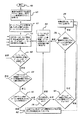
図7は、本発明の発見方法の典型的な一実施形態のフローをシステム内のNIMの観点から示すフロー図である。RDSのフローは一般に終点キャッシュを管理することに主に着目しているので、NIM側の接続から発見処理を観察することが望ましい。
NIM Discovery Flow FIG. 7 is a flow diagram illustrating the flow of an exemplary embodiment of the discovery method of the present invention from the perspective of the NIM in the system. Since the RDS flow is mainly focused on managing the end point cache, it is desirable to observe the discovery process from the connection on the NIM side.
NIMが開始する際、それは選択されたポート上のビーコン・メッセージをリスニングすることによって始まる。好ましい実施形態では、NIMは一般に同じIPアドレスおよびポート番号から、正当なビーコン・メッセージを少なくとも5個連続的に受信し、ビーコン・メッセージ内に含まれるビーコン間隔の少なくとも75%が各ビーコン・メッセージの間で発生するまで、ビーコン・メッセージに応答を試みないようにプログラムされている。この条件は、RDSになりすまし、NIMに取り付けられた機器の制御を得ようとする悪意あるシステムによって、NIMがだまされないようにするという点で、システムのセキュリティを改善するという利点がある。このシステムの別の利点は、NIMが重複するビーコン・メッセージを受信し、NIMとの通信を試みる別のサーバまたはサブネットを示す場合、NIMが重複するビーコン・メッセージを無視し、NIMが受信したビーコン・メッセージのサーバをいずれも登録しないことにある。 When the NIM starts, it begins by listening for a beacon message on the selected port. In a preferred embodiment, the NIM generally receives at least five legitimate beacon messages consecutively from the same IP address and port number, and at least 75% of the beacon interval included in the beacon message is at least 70% for each beacon message. It is programmed not to attempt to respond to beacon messages until it occurs between. This condition has the advantage of improving the security of the system in that the NIM is not fooled by a malicious system trying to impersonate the RDS and gain control of the equipment attached to the NIM. Another advantage of this system is that if the NIM receives a duplicate beacon message and indicates another server or subnet that attempts to communicate with the NIM, the NIM ignores the duplicate beacon message and the beacon received by the NIM • No message server is registered.
一旦NIMのプログラム・ロジックが正当なRDSビーコン・メッセージを受信したと確信すると、NIMはビーコン・メッセージを構文解析し、NIM状態応答メッセージをコンパイルすることによって登録処理を開始する。本発明の多くの実施形態では、NIMはビーコン・メッセージ内の登録モジュロおよびキー・フィールドをチェックし、それ自体がRDSに直ちに報告可能であるか否かを判別するようにプログラムされている。直ちに応答が必要であるか、あるいはこのビーコン・メッセージをスキップし、後のビーコン・メッセージに応答するかをチェックすることは、名目上の発見速度を改善するように設計された最適化方法である。上記のように、多数のNIMへのネットワーク接続が消失し、その後、回復する結果、RDSの登録要求が殺到する可能性がある場合に、この最適化ステップが役に立つ。 Once the NIM program logic believes it has received a valid RDS beacon message, the NIM parses the beacon message and begins the registration process by compiling the NIM status response message. In many embodiments of the invention, the NIM is programmed to check the registration modulo and key fields in the beacon message to determine if it can immediately report to the RDS. Checking if an immediate response is required or skipping this beacon message and responding to a later beacon message is an optimization method designed to improve the nominal discovery speed . As mentioned above, this optimization step is useful when network connections to a large number of NIMs are lost and then recovered, resulting in a flood of RDS registration requests.
RDSビーコン・メッセージが正当であることをNIMが判別すると、NIMは、RDSビーコン・メッセージを常に監視するモードになる。ビーコン閉終点リスト内にNIMの終点が列挙されているか否かを確認するために、RDSから受信した各ビーコン・メッセージを検査する。列挙されているのであれば、列挙された終点のTCP/IP接続がタイムアウトになり、RDSによって閉じられたことを意味し、NIMは同じことを行い、RDSとNIMとが互いに同期していることが保証される。NIMが閉終点リスト内にその終点を一つ以上備えたビーコンを見つけると常に、要求された接続を閉じた後、NIMは状態応答メッセージを送信することを必要とされる。これは、登録モジュロおよびキー・フィールドの値にかかわらず行われる。 If the NIM determines that the RDS beacon message is valid, the NIM is in a mode that constantly monitors the RDS beacon message. Each beacon message received from the RDS is examined to see if the NIM endpoints are listed in the beacon closed endpoint list. If enumerated, it means that the enumerated endpoint TCP / IP connection has timed out and was closed by RDS, NIM does the same thing, and RDS and NIM are in sync with each other Is guaranteed. Whenever a NIM finds a beacon with one or more of its endpoints in the closed endpoint list, after closing the requested connection, the NIM is required to send a status response message. This is done regardless of the registration modulo and key field values.
ビーコン・メッセージの閉終点リスト内に終点が列挙されていない場合、NIMは登録マスクおよびキー・フィールドを調べ、RDSに変更を報告するためのウィンドウが到着しているか否かを判別する。到着していない場合、NIMは単に次のビーコン・メッセージを待機する。NIMのウィンドウが到着している場合、NIMの終点がいずれも接続されておらず、新しいTCP/IP接続をリスニング中であれば、NIMはRDSに状態応答メッセージを送信する。 If the endpoint is not listed in the closed endpoint list of the beacon message, the NIM checks the registration mask and key field to determine if a window has arrived to report the change to the RDS. If not, the NIM simply waits for the next beacon message. When the NIM window has arrived, if none of the NIM endpoints are connected and listening for a new TCP / IP connection, the NIM sends a status response message to the RDS.
図7に示した処理をさらに詳しく説明すると、NIMはボックス400で開始し、NIMの処理はボックス405で最後の既知のRDS位置をIPアドレスの0.0.0.0に設定し、前のビーコン発信源を0.0.0.0に設定する。NIMはさらにボックス405で、ビーコン・カウンタをゼロに設定し、ビーコン・タイムアウト期間を無限に設定する。NIMはさらに、ビーコン・タイムアウト期間が経過したときに起動するために、ボックス410でビーコン・タイマをリセットする。
In more detail, the NIM process starts at
それから、NIMはボックス415で、例えばUDPポート3613(または他のいくつかの選択されたポート)上で受信すべき正当なRDSビーコン・メッセージ、またはビーコン・タイマの期限切れを待機する。NIMの動作プログラムはボックス420で、ビーコン・タイムアウト期間内に正当なビーコン・メッセージを受信したか否かを解析する。正当なビーコン・メッセージを受信した場合、処理はボックス425に進み、NIMはビーコン・メッセージの発信源アドレスおよびポート番号が最後の既知のRDS位置に適合するか否かを判別する。ボックス420で正当なビーコン・メッセージを受信しなかった場合、処理はボックス430に分岐し、NIMはこのIPアドレス用のNIM終点接続をリセットし、ボックス415に戻り、受信すべき正当なRDSビーコン・メッセージを待機する。
The NIM then waits at
ボックス420で正当なビーコン・メッセージを受信し、ボックス425で発信源アドレスおよびポート番号が最後の既知のRDS位置と適合する場合、処理はボックス435に分岐し、NIMはこのIP位置用のビーコン・メッセージの閉終点リスト内に入力があるか否かを判別する。ボックス425で発信源アドレスおよびポート番号が適合しない場合、処理はボックス440に分岐し、NIMは、このビーコン・メッセージの発信源アドレスおよびポート番号が直前に受信したビーコン・メッセージと同じであるか否かを判別する。このビーコン・メッセージの発信源アドレスおよびポート番号が直前に受信したビーコン・メッセージと同じでない場合、処理はボックス445に分岐し、NIMはビーコン・カウンタをゼロにリセットし、ボックス450でビーコン・カウンタを1だけ増加させ、ボックス455でビーコン・カウンタが5以上であるか否かを判別し、ビーコン・カウンタが5以上でない場合、処理は分岐して415に戻り、NIMは正当なRDSビーコン・メッセージを待機し続ける。ボックス455でビーコン・カウンタが5以上であると判別されると、処理はボックス460に進み、NIMは最後の既知のRDS位置が0.0.0.0であるか否かを判別する。最後の既知のRDS位置が0.0.0.0でなかった場合、処理はボックス465に分岐し、NIMはビーコン・タイマが期限切れであるか否かを判別する。ビーコン・タイマが期限切れでなければ、処理はボックス415に戻り、NIMは正当なビーコン・メッセージを待機する。ボックス465でビーコン・タイマが期限切れであるか、あるいはボックス460で最後の既知のRDS位置が0.0.0.0であると判別されれば、処理はボックス470に分岐し、NIMは最新のビーコン・メッセージのアドレスおよびポート番号に最後の既知のRDS位置を設定し、このIPアドレス用の全ての終点接続をリセットする。
If a valid beacon message is received in
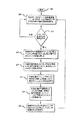
図7に示したように、それから処理はボックス470からボックス505に進み、NIMは、このユニットがRDSに報告できることをシリアル番号マスク/キーが示すか否かを判別する。RDSに報告できることをシリアル番号マスク/キーが示すとNIMが判別した場合、処理はボックス485に進み、NIMはRDSに状態応答メッセージを送信し、ビーコン・タイムアウト期間を、ビーコン・メッセージのビーコン間隔値と、ビーコン・メッセージの閉終点リスト入力寿命値との積に設定し、ボックス410に戻り、ビーコン・タイムアウト期間が経過したときに起動するために、ビーコン・タイマをリセットし、ボックス415に進み、受け取るべき正当なRDSビーコン・メッセージを待機する。
As shown in FIG. 7, processing then proceeds from
ユニットがこの時点でRDSに報告できないことをシリアル番号マスク/キーが示すことをボックス505でNIMが判別すると、処理はボックス510に分岐し、NIMは電源をオンにしてから、ビーコン・メッセージの状態応答メッセージが送られたか否かを判別する。NIMをオンにしてから状態応答メッセージが送られた場合、処理はボックス490に進み、NIMは、ビーコン・タイムアウト期間を、ビーコン・メッセージのビーコン間隔値と、ビーコン・メッセージの閉終点リスト入力寿命値との積に設定し、ボックス410に戻り、ビーコン・タイムアウト期間が経過したときに起動するために、ビーコン・タイマをリセットし、ボックス415に進み、受け取るべき正当なRDSビーコン・メッセージを待機する。状態応答メッセージが送られていないことをボックス510でNIMが判別した場合、処理はボックス485に分岐し、NIMは、状態応答メッセージをRDSに送信し、ボックス490に進み、ビーコン・タイムアウト期間を、ビーコン・メッセージのビーコン間隔値と、ビーコン・メッセージの閉終点リスト入力寿命値との積に設定し、ボックス410に戻り、ビーコン・タイムアウト期間が経過したときに起動するために、ビーコン・タイマをリセットし、ボックス415に進み、受け取るべき正当なRDSビーコン・メッセージを待機する。
If the NIM determines in
ボックス440で、現在のビーコン・メッセージの発信源アドレスおよびポート番号が前のビーコンと同じであると判別された場合、処理はボックス475に進み、NIMは、同じ発信源からの最後のビーコン・メッセージから、少なくとも75%のビーコン間隔が経過したか否かを判別する。同じ発信源からの最後のビーコン・メッセージから、少なくとも75%のビーコン間隔が経過していない場合、処理はボックス415に戻り、NIMは正当なRDSメッセージ・ビーコンを待機する。
If it is determined at
同じ発信源からの最後のビーコン・メッセージから、少なくとも75%のビーコン間隔が経過した場合、処理はボックス450に進み、NIMはビーコン・カウンタを1だけ増加させ、ボックス455でビーコン・カウンタが5以上であるか否かを判別し、ビーコン・カウンタが5以上でない場合、処理は分岐してボックス415に戻り、NIMは正当なRDSビーコン・メッセージを待機し続ける。ボックス455でビーコン・カウンタが5以上であると判別された場合、処理はボックス460に進み、NIMは、最後の既知のRDS位置が0.0.0.0であるか否かを判別する。最後の既知のRDS位置が0.0.0.0でなかった場合、処理はボックス465に分岐し、NIMは、ビーコン・タイマが期限切れであるか否かを判別する。ビーコン・タイマが期限切れでなかった場合、処理はボックス415に戻り、NIMは正当なビーコン・メッセージを待機する。ボックス465でビーコン・タイマが期限切れであるか、ボックス460で最後の既知のRDS位置が0.0.0.0であると判別された場合、処理はボックス470に分岐し、NIMは最新のビーコン・メッセージのアドレスおよびポート番号に最後の既知のRDS位置を設定し、このIPアドレス用の全ての終点接続をリセットする。
If at least 75% of the beacon interval has elapsed since the last beacon message from the same source, processing proceeds to
ボックス425で、現在のビーコンの発信源アドレスおよびポート番号が最後の既知のRDS位置と適合すると判別された場合、処理はボックス435に進み、NIMは、このIP位置用のビーコン・メッセージの閉終点リスト内に入力があるか否かを判別し、入力があるのであれば、ボックス480でこのIPアドレス用のビーコン・メッセージの閉終点リスト内に列挙された終点接続を全てリセットし、ボックス485でRDSに状態応答メッセージを送信し、ボックス490で、ビーコン・タイムアウト期間を、ビーコン・メッセージのビーコン間隔値と、ビーコン・メッセージの閉終点リスト入力寿命値との積に設定し、ボックス410に戻り、ビーコン・タイムアウト期間が経過したときに起動するために、ビーコン・タイマをリセットし、ボックス415に進み、受け取るべき正当なRDSビーコン・メッセージを待機する。
If it is determined at
このIPアドレス用のビーコン・メッセージの閉終点リスト内に入力がないとボックス435で処理が判別した場合、処理はボックス500に分岐し、NIMは全ての終点が接続されているか否かを判別する。全ての終点が接続されていた場合、処理はボックス490に進み、NIMは、ビーコン・タイムアウト期間を、ビーコン・メッセージのビーコン間隔値と、ビーコン・メッセージの閉終点リスト入力寿命値との積に設定し、ボックス410に戻り、ビーコン・タイムアウト期間が経過したときに起動するために、ビーコン・タイマをリセットし、ボックス415に進み、受け取るべき正当なRDSビーコン・メッセージを待機する。
If the process determines in
ボックス500で全ての終点が接続されていないと判別された場合、処理はボックス505に分岐し、NIMは、このユニットがRDSに報告できることをシリアル番号マスク/キーが示すか否かを判別する。NIMがRDSに報告できることをシリアル番号マスク/キーが示すとNIMが判別した場合、処理はボックス485に進み、NIMはRDSに状態応答メッセージを送信し、ボックス490に進み、ビーコン・タイムアウト期間を、ビーコン・メッセージのビーコン間隔値と、ビーコン・メッセージの閉終点リスト入力寿命値との積に設定し、ボックス410に戻り、ビーコン・タイムアウト期間が経過したときに起動するために、ビーコン・タイマをリセットし、ボックス415に進み、受け取るべき正当なRDSビーコン・メッセージを待機する。
If it is determined at
ユニットがこの時点でRDSに報告できないことをシリアル番号マスク/キーが示すことをボックス505でNIMが判別すると、処理はボックス510に分岐し、NIMは電源をオンにしてから、ビーコン・メッセージ状態応答メッセージが送られたか否かを判別する。NIMをオンにしてから状態応答メッセージが送られた場合、処理はボックス490に進み、NIMは、ビーコン・タイムアウト期間を、ビーコン・メッセージのビーコン間隔値と、ビーコン・メッセージの閉終点リスト入力寿命値との積に設定し、ボックス410に戻り、ビーコン・タイムアウト期間が経過したときに起動するために、ビーコン・タイマをリセットし、ボックス415に進み、受け取るべき正当なRDSビーコン・メッセージを待機する。ボックス510で、状態応答メッセージが送られていないとNIMが判別した場合、処理はボックス485に分岐し、NIMは状態応答メッセージをRDSに送信し、ボックス490に進み、ビーコン・タイムアウト期間を、ビーコン・メッセージのビーコン間隔値と、ビーコン・メッセージの閉終点リスト入力寿命値との積に設定し、ボックス410に戻り、ビーコン・タイムアウト期間が経過したときに起動するために、ビーコン・タイマをリセットし、ボックス415に進み、受け取るべき正当なRDSビーコン・メッセージを待機する。
If the NIM determines in
UDPメッセージ・システムの低信頼性によって、ビーコン・パケットはときどき消失することが想定される。一般に、RDSとの接続の消失の拡大を示すように多数の連続的なパケットが消失しない限り、消失したパケットは問題にはならない。各RDSビーコン・パケットは閉終点リスト入力寿命フィールドを有し、前記フィールドはRDSが所定の終点に終点閉情報を送信する連続的なビーコン・メッセージの全数を示す。RDSが送信すべき指示されたビーコン・メッセージ数に対して、十分長い時間ビーコン・メッセージを受け取らなかった場合、NIMは一般に、その接続の一つ以上がRDSによって閉じられたかもしれないと仮定する。このことが生じた場合、NIMは、その接続の一つを意図的に遮断し、その次の応答ウィンドウ中にRDSに報告を行うようにプログラムされている。これは、ビーコン・メッセージ内に閉終点を再送信する機会をRDSに与え、RDSとNIMとは再び同期できる。 Due to the low reliability of the UDP message system, it is assumed that beacon packets are sometimes lost. In general, lost packets are not a problem unless a large number of consecutive packets are lost, indicating an increased loss of connectivity with the RDS. Each RDS beacon packet has a closed endpoint list input lifetime field, which indicates the total number of consecutive beacon messages that the RDS sends endpoint closure information to a given endpoint. If the RDS has not received a beacon message for a long enough time for the indicated number of beacon messages to be transmitted, the NIM generally assumes that one or more of its connections may have been closed by the RDS. . If this happens, the NIM is programmed to intentionally block one of its connections and report to the RDS during its next response window. This gives the RDS an opportunity to retransmit the closed endpoint in the beacon message, and the RDS and NIM can be synchronized again.
NIMが特定のRDSを既に登録していれば、第二発信源からのRDSビーコン・メッセージをいつ調べ始めても、登録されたRDSからのメッセージのために、NIMは第二発信源からのビーコン・メッセージを無視する。しかし、最初のRDSサーバが何らかの理由でビーコン・メッセージの送信を停止し、例えば5個のような所定の数の連続的なビーコン・メッセージを新しいRDSサーバから受信した場合、NIMはその終点接続を全てリセットし、新しいサーバを登録する。これは、主RDSサーバを遮断し、バックアップRDSサーバがその代わりにオンラインになった場合に、NIMがサーバを切り替えることができるので望ましい。当業者には明らかなように、本発明の実施形態は5個の連続的なビーコン・メッセージについて説明されているが、ネットワークの必要性またはシステム設計者の希望に従って、ビーコン・メッセージの数は異なっていてもよいが、本発明の範囲から逸脱することなく、新しいサーバに切り替える前に、多かれ少なかれ5個のビーコン・メッセージを受け取ることができる。 If the NIM has already registered a particular RDS, any time it starts to look for an RDS beacon message from the second source, the NIM will Ignore the message. However, if the first RDS server stops sending beacon messages for any reason and receives a predetermined number of consecutive beacon messages, such as five, from the new RDS server, the NIM Reset everything and register a new server. This is desirable because the NIM can switch servers if the primary RDS server is blocked and the backup RDS server goes online instead. As will be appreciated by those skilled in the art, embodiments of the present invention have been described for five consecutive beacon messages, although the number of beacon messages varies depending on the needs of the network or the desires of the system designer. However, more or less five beacon messages can be received before switching to a new server without departing from the scope of the present invention.
図8は、RDSの発見プログラム・フローを示すブロック図である。上記のように、RDSの発見フローは主に、そのビーコン・メッセージへの応答に注意し、状態応答メッセージで受信したデータを用いて、その終点キャッシュを管理することに関し、前記状態応答メッセージはネットワークに接続されたNIMから受信する。 FIG. 8 is a block diagram showing the RDS discovery program flow. As described above, the discovery flow of RDS is mainly concerned with the response to the beacon message and uses the data received in the status response message to manage its end point cache. Received from the NIM connected to.
ボックス600で開始した後、ボックス605でRDSは、RDSビーコン・メッセージを同報通信しているUDPポート上で受信すべき正当なNIM状態応答メッセージを待機する。メッセージがUDPポート上で受信された場合、処理はボックス610に進み、RDSのプログラム・ロジックは、メッセージが正当なNIM状態応答メッセージであるか否かを判別する。メッセージが正当なNIM状態応答メッセージでない場合、処理はボックス605に戻り、RDSは正当な状態応答メッセージを待機し続ける。
After starting at
メッセージが正当な状態応答メッセージであれば、処理はボックス615に進み、RDSは、状態応答メッセージの「接続済みリスト」にない終点キャッシュ内の全ての入力に対して、動作中のTCP/IP接続を閉じる。これが一旦実現されると、処理はボックス620に進み、RDSは、状態応答メッセージ終点リストのいずれにも存在しない全ての終点について、終点キャッシュからの入力を削除する。この動作が一旦完了すると、処理はボックス625に進み、状態応答メッセージの「リスニング中リスト」内の全ての新しい終点について終点キャッシュに入力を追加し、それからボックス630に進み、状態応答メッセージの「接続済みリスト」内の事前に未知の全ての終点について、ビーコン・メッセージの「閉終点リスト」に入力を追加する。
If the message is a legitimate status response message, processing proceeds to
状態応答メッセージの「接続済みリスト」内の事前に未知の全ての終点について、ビーコン・メッセージの「閉終点リスト」に入力を追加した後、処理はボックス635に進み、RDSは接続されていない終点キャッシュ内の全ての入力に対して、TCP/IP接続の生成を試みる。ボックス635の処理が完了すると、RDSはボックス605に戻り、受信すべき正当なNIM状態応答メッセージを待機する。
After adding entries to the “closed endpoint list” of the beacon message for all previously unknown endpoints in the “connected list” of the status response message, processing proceeds to
接続のリセット
TCP/IP接続がタイムアウトになると常に、接続上で打ち切り切断が行われる。接続の遮断がタイムアウト期間よりそれほど長くなければ、接続の他端のシステムに閉じたことを知らせることもできるが保証はされない。しかし、安全のために、接続の遮断は時間的に延長させ、このような通知が発生しないようにしなければならない。従って、接続が閉じた後、本発明によるシステムおよび方法はいくつかの処理を行い、二つの終点が同期状態に戻れるようにする。処理は、NIMに比べてRDSでは異なり、以降で詳しく説明する。
Connection reset Whenever a TCP / IP connection times out, the connection is aborted. If the disconnection of the connection is not much longer than the timeout period, the system at the other end of the connection can be informed that it has closed, but there is no guarantee. However, for safety, the disconnection of the connection must be extended in time so that such notifications do not occur. Thus, after the connection is closed, the system and method according to the present invention performs some processing to allow the two endpoints to return to synchronization. The processing differs in RDS compared to NIM and will be described in detail later.
NIM用の処理は、RDSによって用いられる処理よりいくぶん簡単である。NIMが接続をリセットすると常に、RDSビーコン・メッセージ内の登録キーをチェックした後、状態応答メッセージを送信する機会を待機するだけで、最近閉じた終点ポートが現在リスニング・モードであることを示す状態応答メッセージを送信する。RDSがこれを確認すると、その終点への接続をリセットし、新しいTCP/IP接続を生成する。NIMは、RDSが最終的にそのポートへの新しいTCP/IP接続を生成するまで、可能であれば未接続の終点を報告し続ける。 The processing for NIM is somewhat simpler than that used by RDS. Whenever the NIM resets the connection, it checks the registration key in the RDS beacon message and then waits for an opportunity to send a status response message, indicating that the recently closed endpoint port is currently in listening mode Send a response message. If the RDS confirms this, it resets the connection to that endpoint and creates a new TCP / IP connection. The NIM continues to report unconnected endpoints if possible until the RDS eventually creates a new TCP / IP connection to that port.
RDSが接続を遮断した場合、ビーコン・メッセージ閉終点リスト内にその終点のアドレスおよびポートを配置しなければならない。閉終点情報は、閉終点リスト入力寿命値と等しい複数のビーコン・メッセージに対してリスト内に発行される。それから、RDSは、ある時点でNIMが状態応答メッセージを送信すると仮定し、前記状態応答メッセージは、終点が再びリスニング・モードになり、NIMからのこのような状態応答メッセージの受信を待機することを示す。 If the RDS breaks the connection, the destination address and port must be placed in the beacon message closed endpoint list. Closed endpoint information is issued in the list for multiple beacon messages equal to the closed endpoint list input lifetime value. The RDS then assumes that the NIM will send a status response message at some point, and the status response message will wait for the end point to enter listening mode again and receive such status response message from the NIM. Show.
NIMが全てのビーコン・メッセージを見逃した場合、接続が回復するとすぐ、NIMのプログラム・ロジックは、RDSに報告する必要があるとそれ自体にフラグを立てる。NIMがRDSに状態応答メッセージを送信することによって最終的にRDSに報告する際、閉終点がなお接続済みとして列挙されていた場合、RDSは再びビーコン・メッセージの閉終点リストにその終点を配置し、ポートがリスニング・モードであるとNIMが応答することを待機する。 If the NIM misses all beacon messages, as soon as the connection is restored, the NIM program logic flags itself as needing to report to the RDS. When the NIM finally reports to the RDS by sending a status response message to the RDS, if the closed endpoint is still listed as connected, the RDS again places the endpoint in the closed endpoint list of the beacon message. Wait for the NIM to respond that the port is in listening mode.
接続管理
ネットワークに接続されたNIMを一旦RDSに登録すると、RDSは各NIM上の各終点にTCP接続を生成する。これは、RDSと終点との間に大きなアプリケーション・レベルのメッセージを送出する高信頼性の手段を提供する。これは、RDSのみがNIMへの接続を生成し、NIMはRDSから発信されていないメッセージを無視するようにプログラムされるという点でも望ましい。さらに、NIMは登録されたRDSからのメッセージのみに応答し、正当なRDSサーバのふりをしようとする悪意あるサーバを含む他のサーバからのメッセージを無視する。
Connection Management Once a NIM connected to the network is registered with the RDS, the RDS creates a TCP connection at each endpoint on each NIM. This provides a reliable means of sending large application level messages between the RDS and the endpoint. This is also desirable in that only the RDS creates a connection to the NIM, and the NIM is programmed to ignore messages that are not originating from the RDS. In addition, the NIM responds only to messages from the registered RDS and ignores messages from other servers, including malicious servers that attempt to pretend to be legitimate RDS servers.
既定値では、TCP/IP接続があきらめ、接続の遮断を宣言するようにプログラムされる前に、TCP/IPプロトコルは、最大9分間、接続したソケット上にデータを再送信しようとする。さらに、TCP/IPプロトコルはデータ送出の消極的確認を行うだけであり、つまり、データをうまく送信できるときではなく、データを送信できないときに送信元に通知するだけである。RDSはこれよりずっと短いタイムアウトを要求し、メッセージ送信の積極的確認を供給するので、アプリケーション・メッセージを送信する際、TCP/IP接続を介して、一般に余分なハンドシェークが行われる。 By default, the TCP / IP protocol will attempt to retransmit data on the connected socket for up to 9 minutes before the TCP / IP connection gives up and is programmed to declare the connection blocked. Furthermore, the TCP / IP protocol only performs passive confirmation of data transmission, that is, not only when the data can be transmitted successfully, but only when the data cannot be transmitted. Since RDS requires a much shorter timeout and provides positive confirmation of message transmission, an extra handshake is typically performed over the TCP / IP connection when sending application messages.
メッセージ・フロー
TCP/IP接続を介して所定の方向に、一度に一つのアプリケーション・メッセージだけが送信される。システムは、TCP/IP接続上で、アプリケーション・レベルのタイムアウトに相当するものを実行できるので、このシリアル化はデータ・フローの制御をかなり簡略化する。ある種の待機インタフェースが望まれる場合、それは一般にアプリケーション層内に実装される。
Message flow Only one application message is sent at a time in a given direction over a TCP / IP connection. This serialization considerably simplifies the control of the data flow, since the system can do what corresponds to an application level timeout on a TCP / IP connection. If a certain standby interface is desired, it is generally implemented in the application layer.
図9は、AとBで識別された二つの終点間のメッセージ・フローの一例を示している。データを送信後、送信元は受信先から一般に長さ0バイトのメッセージである肯定応答を受け取るまで待機しなければならず、その後、別のデータ・メッセージの送信が可能になる。接続は双方向であるので、このフローは図10に示したように、同時に双方向で発生できる。 FIG. 9 shows an example of a message flow between two endpoints identified by A and B. After sending the data, the sender must wait until receiving an acknowledgment, typically a zero-byte message, from the receiver, after which another data message can be sent. Since the connection is bidirectional, this flow can occur in both directions simultaneously, as shown in FIG.
図11はTCP/IP接続を介した典型的なデータ・フローを示しており、この例では送信元Aはアプリケーション・レベルのタイムアウトを行う。第二データ・メッセージ用の肯定応答がタイムアウト期間内に到達しなかったので、終点Aは機器間のTCP接続を強制的に閉じる。終点Bからの肯定応答が最終的に送信元Aに到達した場合、TCPスタックは接続が閉じられていることを示す低レベル接続リセット・エラーで応答する。終点Bによって送信される別の任意のメッセージも、同じエラーを受信する。 FIG. 11 shows a typical data flow over a TCP / IP connection. In this example, source A performs an application level timeout. Since the acknowledgment for the second data message has not arrived within the timeout period, endpoint A forcibly closes the TCP connection between the devices. If the acknowledgment from endpoint B eventually reaches source A, the TCP stack responds with a low level connection reset error indicating that the connection is closed. Any other message sent by endpoint B will receive the same error.
データの暗号化
悪意ある攻撃に対して機密性の高い患者データを保護し、システム全体を堅固にするために、本発明の接続プロトコルの一実施形態は、ネットワークを介して送信される全てのデータ上で暗号化を行う。説明される本発明の実施形態では暗号化は四ステップ処理であり、各ステップは異なるセキュリティ上の懸念に対処するように設計されている。
Data encryption In order to protect sensitive patient data against malicious attacks and to make the entire system robust, one embodiment of the connection protocol of the present invention provides for all data transmitted over the network. Encrypt above. In the described embodiment of the invention, encryption is a four-step process, and each step is designed to address different security concerns.
図12は、本発明の一実施形態の暗号化メッセージ700の構造を示している。図のデータ暗号化方式の特定の実施形態はストリームデータをサポートしておらず、NIMとRDSの間で送信される全てのメッセージは、所定の長さでなければならない。この実施形態は所定の長さについて説明しているが、本発明の他の実施形態は、異なる長さを備えたメッセージを暗号化可能な暗号方式を用いることを考慮し、それも本発明の意図した範囲内である。
FIG. 12 shows the structure of an
暗号化処理
図の実施形態の暗号化処理の最初のステップは、送信されるデータに複数の10バイトを埋め込むことである。これは、最終的な暗号化ステップが16バイトの固定ブロック・サイズの対称ブロック暗号化を用いるために必要となる。埋め込むデータは、ある定数またはランダム値に明示的に設定されなければならず、メッセージ・バッファの事前に存在するメモリ内容が埋め込み領域内にそのまま残ることは許されない。埋め込みデータは、メッセージ700のメッセージ・データ・フィールド705に格納される。
Encryption Process The first step in the encryption process of the illustrated embodiment is to embed multiple 10 bytes in the data to be transmitted. This is necessary because the final encryption step uses symmetric block encryption with a fixed block size of 16 bytes. The embedded data must be explicitly set to some constant or random value, and the pre-existing memory contents of the message buffer are not allowed to remain in the embedded area. The embedded data is stored in the message data field 705 of the
それから、図12に示したように、四つのフィールド715,720,725および730を有するセキュリティ・ヘッダ710を各メッセージ700に追加する。セキュリティ・ヘッダ710のトランザクション・キー・フィールド715はランダムに生成された32ビット値を有し、その値はシステムで利用可能な最も高暗号強度の乱数発生器によって生成される。セキュリティ・ヘッダ710の発信源IPアドレス・フィールド720は送信元のIPアドレスを有し、このフィールドは送信元を認証するためのデジタル署名として受信先によって使用される。セキュリティ・ヘッダ710のデータ・サイズ・フィールド725は、埋め込み前の元の平文メッセージのバイト数を有する。最後に、セキュリティ・ヘッダ710のMTUサイズ・フィールド730は、送信元が単一のデータグラムで処理可能なバイトの最大数を有し、この実施形態では16バイト未満には決してならない。
Then, as shown in FIG. 12, a
セキュリティ・ヘッダ710をメッセージ700の最初に追加した後、セキュリティ・フッタ735をメッセージ700の終わりに追加する。図の実施形態のセキュリティ・フッタ735は、例えば、MD5メッセージ・ダイジェスト・アルゴリズムを用いて生成されたセキュリティ・ヘッダおよび埋め込みメッセージのハッシュを有する。このセキュリティ・フッタ735は、送信中、メッセージが改竄されたか否かを判別するために、メッセージの受信先によって使用される。
After adding a
メッセージ全体が一旦まとめられると、セキュリティ・ヘッダ内のトランザクション・キーと、メッセージ全体の排他的論理和とを一度に32バイトずつとり、トランザクション・キー自体を取り除く。データを「ソルト」することは、発信源IPアドレス等の連続的なメッセージの静的部分が常に同じように暗号化されないようにするために役立ち、本発明の実施形態の暗号化方法のセキュリティをさらに強化する。 Once the entire message is collected, the transaction key in the security header and the exclusive OR of the entire message are taken 32 bytes at a time, and the transaction key itself is removed. “Salting” the data helps to ensure that the static part of a continuous message, such as the source IP address, is not always encrypted in the same way, and enhances the security of the encryption method of the embodiments of the present invention. Further strengthen.
データをソルトした後、例えば、AESブロック暗号化を用いて、両方のヘッダを含むメッセージ全体を共通キーで暗号化する。それから、暗号化したメッセージを所定の受信先に送信する。 After salting the data, the entire message including both headers is encrypted with a common key, for example using AES block encryption. Then, the encrypted message is transmitted to a predetermined recipient.
復号化処理
一旦メッセージを受信すると、受信先のプログラム・ロジックは正当なメッセージを受信したか否かをまず判別しなければならない。この処理は、メッセージをデータグラムベースのUDP接続で受信したか、ストリームベースのTCP接続で受信したかに応じてやや異なる。
Decryption process Once a message is received, the recipient's program logic must first determine whether a valid message has been received. This process is slightly different depending on whether the message is received via a datagram based UDP connection or a stream based TCP connection.
一般に、復号化は、暗号化処理の逆にすぎない。本発明の一実施形態では、AESブロック暗号化を用いてメッセージを復号化し、それからセキュリティ・ヘッダ内で見つけたトランザクジョン・キーを用いて逆ソルトする。一旦これが完了すると、MD5メッセージ・ダイジェスト・アルゴリズムを用いて、セキュリティ・ヘッダと埋め込みデータをハッシュし、セキュリティ・フッタ内に格納したハッシュと結果を比較する。ハッシュが適合した場合、セキュリティ・ヘッダ内の発信元IPアドレスをメッセージの実際の発信源に対してチェックする。それから、セキュリティ・ヘッダ内のデータ・サイズ・フィールドをチェックし、埋め込まれたメッセージ・データの実際の大きさに等しいか、多くとも15バイト未満であるかを確認する。これらの最後の二つのチェックを通れば、データは正当であると考えられ、将来的に使用するためにメッセージから抽出される。 In general, decryption is just the reverse of the encryption process. In one embodiment of the invention, the message is decrypted using AES block encryption and then reverse salted using the transaction key found in the security header. Once this is complete, the MD5 message digest algorithm is used to hash the security header and embedded data and compare the result with the hash stored in the security footer. If the hash matches, the source IP address in the security header is checked against the actual source of the message. It then checks the data size field in the security header to see if it is equal to the actual size of the embedded message data, or at most less than 15 bytes. If these last two checks are passed, the data is considered valid and extracted from the message for future use.
TCP接続では、一定期間、一度に数バイトずつ、暗号化されたメッセージをゆっくり送出できる。これ自体は欠点ではないが、ただし、TCP接続は、メッセージの開始または終了の概念を持たない。従って、受信先は、TCP接続上で送信される連続的なメッセージの間の境界の判別において積極的な役割を果たす。その結果、復号化処理は、TCP接続上で用いられる場合はやや変化する。 With TCP connection, encrypted messages can be sent out slowly several bytes at a time for a certain period. This is not a drawback in itself, but a TCP connection has no concept of starting or ending a message. Thus, the recipient plays an active role in determining the boundary between successive messages sent over the TCP connection. As a result, the decryption process changes slightly when used over a TCP connection.
本発明の図の実施形態の方法を用いて、TCP接続上で受信したメッセージを復号化する場合、AESブロック暗号化を用いて最初の16バイトを復号化し、トランザクション・キーを用いて逆ソルトし、それらが正当なセキュリティ・ヘッダを有するか否かを検査する。送信元IPアドレスが適合し、データ・サイズが所定の制限内であれば、セキュリティ・ヘッダ内で指定されたサイズのメッセージを受信するまで、システムは受信すべき追加のバイトを待機し続ける。しかし、値のどちらかが不当な場合は、接続は遮断する。 When decrypting a message received over a TCP connection using the method of the illustrated embodiment of the present invention, the first 16 bytes are decrypted using AES block encryption and de-sorted using the transaction key. Check if they have a valid security header. If the source IP address matches and the data size is within the predetermined limits, the system continues to wait for additional bytes to receive until it receives a message of the size specified in the security header. However, if either of the values is invalid, the connection is blocked.
特定のサイズのメッセージに対して、必要なバイト数を一旦受信すると、残りのメッセージを復号化し、逆ソルトし、MD5ハッシュを確認する。確認が成功した場合、データは正当であると考えられ、ハッシュ確認が失敗した場合は、接続は遮断される。 Once the required number of bytes is received for a message of a particular size, the remaining messages are decrypted, de-salt, and the MD5 hash is confirmed. If the verification is successful, the data is considered valid, and if the hash verification fails, the connection is blocked.
応答メッセージ内のトランザクションID
本発明の原理によると、UDP接続上で送信されるデータだけが、RDSビーコン・メッセージおよびNIM状態応答メッセージである。さらに、状態応答メッセージはビーコン・メッセージの応答としてだけ送信され、ビーコン・メッセージ毎に一つの状態メッセージだけが送信される。同様に、TCP接続だけがメッセージを送信し、肯定応答がそれらのメッセージに応答する。しかし、複数の応答が送信されることは決してない(例えば、複数のビーコン応答または複数の肯定応答)。このため、本発明の原理を用いる全てのメッセージ交換は、1:1要求/応答メッセージ比率であると一般的にいうことができる。
Transaction ID in the response message
According to the principles of the present invention, the only data transmitted over the UDP connection is the RDS beacon message and the NIM status response message. Further, the status response message is transmitted only as a response to the beacon message, and only one status message is transmitted per beacon message. Similarly, only TCP connections send messages and acknowledgments respond to those messages. However, multiple responses are never sent (eg, multiple beacon responses or multiple acknowledgments). Thus, all message exchanges using the principles of the present invention can be generally referred to as a 1: 1 request / response message ratio.
メッセージのセキュリティ・ヘッダ内のトランザクションIDは、暗号化処理を増強するソルト値としてのみ提供されるが、これはその機能だけではない。さらに、トランザクションIDは、UDPおよびTCP接続の両方の上のメッセージ間を同期させる。 The transaction ID in the message security header is provided only as a salt value that enhances the encryption process, but this is not the only function. Furthermore, the transaction ID synchronizes between messages on both UDP and TCP connections.
送信される各要求は、ランダムに選択されたトランザクションIDを有する。しかし、応答メッセージは、それら自体のトランザクションIDは選択しない。その代わり、要求メッセージからのトランザクションIDを再利用し、それら自体のトランザクションIDフィールドをゼロに設定する。元の要求側が、ゼロのトランザクションIDを備えた応答を受信すると、データを送信および逆ソルトしようとした最新の要求からのトランザクションIDを用いていることがわかる。その結果、トランザクションIDが適合する場合だけ、データは正しく復号化される。 Each request sent has a randomly selected transaction ID. However, the response message does not select their own transaction ID. Instead, it reuses the transaction ID from the request message and sets its own transaction ID field to zero. When the original requester receives a response with a zero transaction ID, it knows that it is using the transaction ID from the most recent request that attempted to send and reverse salt the data. As a result, data is correctly decrypted only when the transaction ID matches.
ゼロバイトの肯定応答を受信するまで、TCP接続上では新しいメッセージは送信されないが、この方法は、余分な確実性を提供する点で有利である。暗号化したメッセージ内のデータ・サイズがゼロであっても、セキュリティ・ヘッダ/フッタはなお適切に復号化し、正当でなければならず、そうでなければ接続は遮断される。これは、所定の要求に対して所定の肯定応答が意図するより、完全な確実性を提供する。 Until a zero byte acknowledgment is received, no new messages are sent over the TCP connection, but this method is advantageous in providing extra certainty. Even if the data size in the encrypted message is zero, the security header / footer must still be properly decrypted and valid, otherwise the connection will be blocked. This provides more certainty than a predetermined acknowledgment is intended for a given request.
本発明の方法は、UDP接続を用いる場合でも、バラバラのデータグラム送出から生じるシーケンス・エラーを防止できるのでさらに有利である。RDSは各ビーコン・メッセージに対して新しいトランザクションIDを選択するので、トランザクションIDは、特定の状態応答メッセージが最新のビーコン・メッセージに対する応答であるか、あるいはネットワークによって遅延された古い応答であるかを確認する手段を提供する。 The method of the present invention is further advantageous because it prevents sequence errors resulting from disjoint datagram transmission even when using a UDP connection. Since RDS selects a new transaction ID for each beacon message, the transaction ID indicates whether a particular status response message is a response to the latest beacon message or an old response delayed by the network. Provide a means to confirm.
MTU発見
暗号化されたメッセージの各々の最初のセキュリティ・ヘッダ710(図12)はMTUサイズ・フィールド730を有し、システムが単一のデータグラムで処理できる最大バイト数を示す。このフィールドは常に、肯定応答メッセージを含む各メッセージ内に設定される。従って、システムはゼロバイトのデータグラムを送信し、肯定応答メッセージのMTUサイズ・フィールドを調べることによって、別のシステムのMTUサイズを安全に発見できる。この手順は選択可能であるが、送信元がMTUサイズより大きな任意の受信メッセージを拒否できるので有利である。
MTU Discovery The first security header 710 (FIG. 12) of each encrypted message has an
AES暗号モード
AESブロック暗号は、電子クック・ブック(ECB)および暗号ブロック連鎖(CBC)モードの両方で使用される。CBCモードは、既に暗号化されたブロックからのデータを用いて、次のブロックのデータをソルトし暗号化するので、わずかであるがより安全である。このようなモードを用いる場合、暗号化されたストリームを復号化するためにストリーム全体の複製を得なければならず、特定の抜粋を絞り込むことが難しくなる。
AES Cipher Mode AES block cipher is used in both Electronic Cookbook (ECB) and Cipher Block Chaining (CBC) modes. The CBC mode is slightly more secure because it uses data from an already encrypted block to salt and encrypt the data in the next block. When using such a mode, a copy of the entire stream must be obtained in order to decrypt the encrypted stream, making it difficult to narrow down a particular excerpt.
本発明の原理によると、全てのTCP接続はAES暗号に対してCBCモードを用いてセキュリティを改善するが、他のモードを用いることもでき、本発明の範囲内にあるものとする。CBCモードを用いる場合、データ・ストリームの両端が互いに同期的に開閉されるので不利ではない。しかし、RDSビーコン・メッセージと、ビーコン・メッセージに対するNIM状態応答メッセージはUDPチャネル上に送信され、従って、同期化することなく送受信され、RDSが送信を開始したよりも遥か後に、NIMの電源をオンにし、ビーコン・メッセージを受信し始めることができる。このため、既に同報通信されたビーコン・メッセージ上でNIMが「キャッチアップ」する方法がないので、UDPチャネルではECBモードを用いることが望ましい。 According to the principles of the present invention, all TCP connections use the CBC mode for AES ciphers to improve security, but other modes can be used and are within the scope of the present invention. When using the CBC mode, both ends of the data stream are opened and closed synchronously, which is not disadvantageous. However, the RDS beacon message and the NIM status response message for the beacon message are transmitted over the UDP channel and are therefore sent and received without synchronization, and the NIM is turned on long after the RDS starts transmitting. And can start receiving beacon messages. For this reason, there is no way for the NIM to “catch up” on beacon messages that have already been broadcast, so it is desirable to use ECB mode on the UDP channel.
本発明の別の実施形態では、医療機器はNIMを有することができ、医療機器をネットワークに接続した際、NIMは周期的に「再起動」するが、それ以外では停止中または電源オフになるようにプログラムされている。この実施形態では、NIMは上記のように再起動し、ビーコン・メッセージのためにネットワークをリスニングし始める。この実施形態は、医療機器内のメモリ、または医療機器と接続した記憶媒体内に存在する様々なデータベースの更新を受信できるようにNIMをネットワークに接続できるので有利であり、それは医療機器の電源をオンにする際、起動に必要な時間を短縮できる。任意の必要な更新を受信した後、NIMは電源をオフにし、「スリープモード」に戻るようにプログラムされている。NIMは、データを受信することなく、特定の時間が経過した後に電源オフにすることもでき、それは医療機器または関連装置の一つ以上のデータベースの更新が不要であることを示している。別の実施形態では、NIMは医療機器とは別個に再起動し、キャッシュまたは他のメモリ内に任意のデータ更新を格納するようにプログラムされており、医療機器が電源オンになった後、前記データを医療機器に提供できる。この実施形態は、NIMに電力を供給するだけなので、バッテリ電力を節約し、バッテリ寿命を延ばすという点で有利である。 In another embodiment of the present invention, the medical device can have a NIM, and when the medical device is connected to the network, the NIM periodically “restarts”, otherwise it is stopped or powered off Is programmed to do so. In this embodiment, the NIM restarts as described above and begins listening to the network for beacon messages. This embodiment is advantageous because the NIM can be connected to a network so that it can receive various database updates that reside in memory within the medical device or in a storage medium connected to the medical device, which powers the medical device. When turned on, the time required for startup can be shortened. After receiving any necessary updates, the NIM is programmed to turn off and return to “sleep mode”. The NIM can also be powered off after a certain amount of time without receiving data, indicating that no update of one or more databases of medical devices or related devices is required. In another embodiment, the NIM is programmed to restart separately from the medical device and store any data updates in a cache or other memory, after the medical device is powered on, Data can be provided to medical devices. This embodiment is advantageous in that it saves battery power and extends battery life because it only supplies power to the NIM.
さらに別の実施形態では、本発明は、このような医療機器等の資産を配置するシステムおよび方法を提供し、それらは例えば輸液ポンプまたは生命徴候監視装置であってもよく、一般に患者の処置の過程で一つの場所から別の場所に移動される。この実施形態は、無線接続を用いて、施設ネットワークと通信する移動型医療機器を備えた施設内で特に有利である。このようなネットワークでは、移動型医療機器は、施設全体に配置した送受信機を介してネットワークと通信する。各送受信機は、MACアドレスを用いてネットワーク上で識別される。各送受信機の位置、および各MACアドレスの位置は、システムにとって既知になる。従って、移動型医療機器を配置したいケア提供者は、接続される機器のリストおよびMACアドレスのリストを備え、少なくとも機器が無線送受信機の領域内に配置される範囲で、機器のおよその位置を判別できる。一般に、医療施設内のこのような受信器の範囲は、およそ6フィート程度である。 In yet another embodiment, the present invention provides systems and methods for deploying assets such as such medical devices, which may be, for example, infusion pumps or vital signs monitoring devices, generally for patient treatment. Moved from one place to another in the process. This embodiment is particularly advantageous in facilities with mobile medical devices that communicate with the facility network using wireless connections. In such a network, the mobile medical device communicates with the network via transceivers arranged throughout the facility. Each transceiver is identified on the network using a MAC address. The location of each transceiver and the location of each MAC address is known to the system. Therefore, a care provider who wants to place a mobile medical device has a list of connected devices and a list of MAC addresses, and determines the approximate location of the device at least as long as the device is placed in the area of the wireless transceiver. Can be determined. In general, the range of such receivers within a medical facility is on the order of approximately 6 feet.
さらに別の実施形態では、本発明は、施設内に存在することが知られているが、所定の期間、ビーコン・メッセージに応答していない機器の監視リストを確立することによって、移動型医療機器を配置するシステムおよび方法を提供する。この実施形態では、システムは、機器がオンになるか、または無線の範囲内に来たときに機器にフラグを立て、RDSによって送信されたビーコン・メッセージへの応答を開始するようにプログラムされている。それから、フラグを立てた医療機器が配置されたという報告を施設に提供できる。 In yet another embodiment, the present invention provides a mobile medical device by establishing a monitoring list of devices that are known to exist in a facility but have not responded to beacon messages for a predetermined period of time. Systems and methods for deploying are provided. In this embodiment, the system is programmed to flag the device when the device turns on or comes within range and initiates a response to the beacon message sent by the RDS. Yes. A report can then be provided to the facility that the flagged medical device has been placed.
本明細書では、本発明の特定の実施形態を説明しているが、当業者は発明の概念から逸脱することなく、本発明の変形を考案することができる。 While specific embodiments of the invention have been described herein, those skilled in the art can devise variations of the invention without departing from the inventive concept.
Claims (11)
サーバからのビーコン信号を選択されたポートからネットワーク上に同報通信すること、
前記ビーコン信号に応答して、ネットワーク上で通信する前記クライアント機器によって生成された応答信号を前記選択されたポートでリスニングすることであって、前記応答信号は、前記クライアント機器との通信セッションを開くために前記サーバにより使用される終点リストを含み、該終点リストは、前記サーバと活性通信状態にある終点のリストと、前記サーバからの新たな接続のためにリスニング中の終点のリストとを含む、前記リスニングすること、
前記ビーコン信号は、前記サーバとの通信セッションを終了した全ての終点を特定する閉終点リストを含むものであり、
前記応答信号に基づいて前記サーバと以前に通信状態にあり、かつ前記サーバと活性通信状態にある前記終点のリストに含まれる終点との通信セッションを閉じること、
前記応答信号に基づいて前記サーバと以前に通信状態にある終点を前記閉終点リストに加えることにより前記閉終点リストを更新することを備える方法。 A method for communicating with a client device over a network,
Broadcasting the beacon signal from the server to the network from the selected port;
In response to the beacon signal, the method comprising: listening for response signals generated by the client device that communicates over a network with the selected port, the response signal, opening a communication session with the client device Includes an endpoint list used by the server to include a list of endpoints in active communication with the server and a list of endpoints that are listening for new connections from the server. The listening,
Before SL beacon signal includes those 閉終point list to identify all endpoints that terminate the communication session with the server,
Closing a communication session with an endpoint included in the list of endpoints previously in communication with the server and in active communication with the server based on the response signal;
Updating the closed endpoint list by adding an endpoint previously in communication with the server to the closed endpoint list based on the response signal .
ネットワーク上に同報通信された前記ビーコン信号を受信すること、
正当なビーコン信号が受信されたか否かを判別すること、
正当なビーコン信号への応答をネットワーク上に送信して、前記クライアント機器を前記サーバに登録すること、
を備える方法。 The method of claim 1, further comprising:
Receiving the beacon signal broadcast on the network;
Determining whether a valid beacon signal has been received,
Sending a response to a valid beacon signal over the network to register the client device with the server;
A method comprising:
前記サーバと前記クライアント機器との間で安全な通信リンクを確立すること、
前記安全な通信リンクが閉じられたか否かを判別すること、
前記クライアント機器によって維持された接続のリストをリセットすること、
正当なビーコン信号をリスニングすること、
前記安全な通信リンクを再確立すること、
を備える方法。 The method of claim 1, further comprising:
Establishing a secure communication link between the server and the client device;
Determining whether the secure communication link is closed;
Resetting the list of connections maintained by the client device;
Listening for a legitimate beacon signal,
Re-establishing the secure communication link;
A method comprising:
ネットワークに接続されたサーバを動作させ、該サーバの選択されたポートからネットワーク上にビーコン信号を同報通信すること、
前記クライアント機器を動作させ、前記選択されたポートからの前記ビーコン信号を受信すること、
ネットワーク上で受信された前記ビーコン信号に応答して、前記クライアント機器から前記選択されたポートに応答信号を送信し、前記サーバが受信すること、
前記応答信号は、前記クライアント機器との通信セッションを開くために前記サーバにより使用される終点リストを含み、該終点リストは、前記サーバと活性通信状態にある終点のリストと、前記サーバからの新たな接続のためにリスニング中の終点のリストとを含み、
前記ビーコン信号は、前記サーバとの通信セッションを終了した全ての終点を特定する閉終点リストを含むものであり、
前記応答信号に基づいて前記サーバと以前に通信状態にあり、かつ前記サーバと活性通信状態にある前記終点のリストに含まれる終点との通信セッションを閉じること、
前記応答信号に基づいて前記サーバと以前に通信状態にある終点を前記閉終点リストに加えることにより前記閉終点リストを更新することを備える方法。 A method for communicating with a client device connected to a network,
Operating a server connected to the network and broadcasting a beacon signal over a network from a selected port of the server;
Operating the client device and receiving the beacon signal from the selected port;
Transmitting a response signal from the client device to the selected port in response to the beacon signal received on the network, and receiving the server;
Before Symbol response signal includes the endpoints list used by the server to open a communication session with the client device, said end point list, a list of end point in said server and an active communication state, from said server Including a list of listening endpoints for new connections,
The beacon signal includes those 閉終point list to identify all endpoints that terminate the communication session with the server,
Closing a communication session with an endpoint included in the list of endpoints previously in communication with the server and in active communication with the server based on the response signal;
Updating the closed endpoint list by adding an endpoint previously in communication with the server to the closed endpoint list based on the response signal .
前記クライアント機器と前記サーバとの間で安全な通信セッションを確立すること、
を備える方法。 The method of claim 5 , further comprising:
Establishing a secure communication session between the client device and the server;
A method comprising:
前記サーバと前記クライアント機器との間で通信される情報を復号化すること、
を備える方法。 The method of claim 7 , further comprising:
Decrypting information communicated between the server and the client device;
A method comprising:
ネットワークであって、該ネットワークに接続された機器の間でデータを運ぶためのネットワークと、
前記ネットワークと通信するサーバであって、該サーバの選択されたポートを介して、選択された間隔で前記ネットワーク上にビーコン信号を同報通信するようにプログラムされたプロセッサを有するサーバと、
前記ネットワークと通信するクライアント機器であって、前記選択されたポートからの前記ビーコン信号のために前記ネットワークをリスニングするとともに、状態メッセージを用いて前記ビーコン信号に応答するようにプログラムされたクライアント機器と
を備え、
前記状態メッセージは、前記クライアント機器との安全な通信セッションを確立する際に前記サーバによって使用される終点のリストを含み、該終点リストは、前記サーバと活性通信状態にある終点のリストと、前記サーバからの新たな接続のためにリスニング中の終点のリストとを含み、
前記状態メッセージを受信する際、前記サーバは前記状態メッセージに含まれる前記終点のリストを用いて、前記クライアント機器との通信セッションを確立するように構成され、
前記プロセッサは、前記サーバとの通信セッションを終了した全ての終点を特定する閉終点リストを含むビーコン信号を同報通信し、前記状態メッセージに基づいて前記サーバと以前に通信状態にあり、かつ前記サーバと活性通信状態にある前記終点のリストに含まれる終点との通信セッションを閉じ、前記状態メッセージに基づいて前記サーバと以前に通信状態にある終点を前記閉終点リストに加えることにより前記閉終点リストを更新するようにプログラムされている、システム。 A system for managing patient care in a facility,
A network for carrying data between devices connected to the network;
A server in communication with the network, the server having a processor programmed to broadcast a beacon signal over the network at selected intervals via a selected port of the server;
A client device that communicates with the network, the client device programmed to listen to the network for the beacon signal from the selected port and to respond to the beacon signal using a status message; With
The status message includes a list of endpoints used by the server in establishing a secure communication session with the client device, the endpoint list including a list of endpoints in active communication with the server; A list of listening endpoints for new connections from the server,
When receiving the status message, the server is configured to establish a communication session with the client device using the list of endpoints included in the status message;
The processor broadcasts a beacon signal including a closed endpoint list that identifies all endpoints that have terminated a communication session with the server, has previously been in communication with the server based on the status message, and Closing endpoints by closing a communication session with an endpoint included in the list of endpoints in active communication with the server and adding endpoints previously in communication with the server to the closed endpoint list based on the status message A system that is programmed to update the list .
Applications Claiming Priority (3)
| Application Number | Priority Date | Filing Date | Title |
|---|---|---|---|
| US52618203P | 2003-12-01 | 2003-12-01 | |
| US60/526,182 | 2003-12-01 | ||
| PCT/US2004/040071 WO2005055560A1 (en) | 2003-12-01 | 2004-12-01 | System and method for network discovery and connection management |
Publications (2)
| Publication Number | Publication Date |
|---|---|
| JP2007513579A JP2007513579A (en) | 2007-05-24 |
| JP5259085B2 true JP5259085B2 (en) | 2013-08-07 |
Family
ID=34652428
Family Applications (1)
| Application Number | Title | Priority Date | Filing Date |
|---|---|---|---|
| JP2006542679A Expired - Fee Related JP5259085B2 (en) | 2003-12-01 | 2004-12-01 | System and method for network discovery and connection management |
Country Status (8)
| Country | Link |
|---|---|
| US (1) | US7788369B2 (en) |
| EP (1) | EP1733529A2 (en) |
| JP (1) | JP5259085B2 (en) |
| AU (1) | AU2004311010B2 (en) |
| CA (1) | CA2547973A1 (en) |
| NZ (1) | NZ547850A (en) |
| WO (1) | WO2005055560A1 (en) |
| ZA (1) | ZA200604464B (en) |
Families Citing this family (102)
| Publication number | Priority date | Publication date | Assignee | Title |
|---|---|---|---|---|
| US8572254B2 (en) * | 2004-04-08 | 2013-10-29 | Worldextend, Llc | Systems and methods for establishing and validating secure network sessions |
| US20060265506A1 (en) * | 2004-04-08 | 2006-11-23 | World Extend Llc | Systems and methods for establishing and validating secure network sessions |
| US20060123120A1 (en) * | 2004-04-08 | 2006-06-08 | Thomas Merkh | Methods for establishing and validating sessions |
| US7743151B2 (en) * | 2004-08-05 | 2010-06-22 | Cardiac Pacemakers, Inc. | System and method for providing digital data communications over a wireless intra-body network |
| WO2006050206A1 (en) * | 2004-10-29 | 2006-05-11 | Draeger Medical Systems, Inc. | Automatic wireless pan/lan switching |
| US9275052B2 (en) | 2005-01-19 | 2016-03-01 | Amazon Technologies, Inc. | Providing annotations of a digital work |
| US8131647B2 (en) * | 2005-01-19 | 2012-03-06 | Amazon Technologies, Inc. | Method and system for providing annotations of a digital work |
| JP2006295878A (en) * | 2005-01-25 | 2006-10-26 | Ricoh Co Ltd | Image forming device |
| US20060224719A1 (en) * | 2005-03-30 | 2006-10-05 | Integrated Informatics, Inc. | Operator simulator and non-invasive interface engine |
| US7594020B2 (en) * | 2005-05-31 | 2009-09-22 | Microsoft Corporation | Re-establishing a connection for an application layer via a service layer |
| US20070005773A1 (en) * | 2005-05-31 | 2007-01-04 | Microsoft Corporation | Re-establishing a connection for an application layer via a service layer using delay |
| US20070005987A1 (en) * | 2005-06-30 | 2007-01-04 | Durham Lenitra M | Wireless detection and/or containment of compromised electronic devices in multiple power states |
| WO2007030877A1 (en) * | 2005-09-12 | 2007-03-22 | Resmed Ltd | Network enabled flow generator |
| US8352449B1 (en) | 2006-03-29 | 2013-01-08 | Amazon Technologies, Inc. | Reader device content indexing |
| US20070248058A1 (en) * | 2006-04-20 | 2007-10-25 | Victor Fajardo | Fast link-down detection systems and methods |
| US20070288265A1 (en) * | 2006-04-28 | 2007-12-13 | Thomas Quinian | Intelligent device and data network |
| US8601102B1 (en) * | 2006-05-31 | 2013-12-03 | Juniper Networks, Inc. | Dynamic access management for network security |
| US8583809B2 (en) * | 2006-09-07 | 2013-11-12 | Blackberry Limited | Destroying a secure session maintained by a server on behalf of a connection owner |
| US9672533B1 (en) | 2006-09-29 | 2017-06-06 | Amazon Technologies, Inc. | Acquisition of an item based on a catalog presentation of items |
| US8725565B1 (en) | 2006-09-29 | 2014-05-13 | Amazon Technologies, Inc. | Expedited acquisition of a digital item following a sample presentation of the item |
| US7848263B2 (en) | 2006-11-28 | 2010-12-07 | Marvell International, Ltd. | Simplified auto-configuration and service discovery in ad-hoc networks |
| US7865817B2 (en) | 2006-12-29 | 2011-01-04 | Amazon Technologies, Inc. | Invariant referencing in digital works |
| US9973421B2 (en) * | 2006-12-29 | 2018-05-15 | Orange | Method and device for connection management in a telecommunication network |
| US7751807B2 (en) | 2007-02-12 | 2010-07-06 | Oomble, Inc. | Method and system for a hosted mobile management service architecture |
| US8024400B2 (en) | 2007-09-26 | 2011-09-20 | Oomble, Inc. | Method and system for transferring content from the web to mobile devices |
| US7716224B2 (en) | 2007-03-29 | 2010-05-11 | Amazon Technologies, Inc. | Search and indexing on a user device |
| US9665529B1 (en) | 2007-03-29 | 2017-05-30 | Amazon Technologies, Inc. | Relative progress and event indicators |
| EP1981245A1 (en) * | 2007-04-13 | 2008-10-15 | Liconic Ag | Method and product for controlling laboratory equipment |
| US7853900B2 (en) | 2007-05-21 | 2010-12-14 | Amazon Technologies, Inc. | Animations |
| US9264483B2 (en) | 2007-07-18 | 2016-02-16 | Hammond Development International, Inc. | Method and system for enabling a communication device to remotely execute an application |
| US20090118591A1 (en) * | 2007-11-02 | 2009-05-07 | H3 System Co., Ltd. | Method and apparatus for collecting data from household medical devices |
| US20090147723A1 (en) * | 2007-12-07 | 2009-06-11 | Hong Kong Applied Science and Technology Research Institute Company Limited | Method and Device for Data Routing and Bandwidth Reservation in Small Scale Distributed Networks |
| US20090177142A1 (en) | 2008-01-09 | 2009-07-09 | Smiths Medical Md, Inc | Insulin pump with add-on modules |
| US8423889B1 (en) | 2008-06-05 | 2013-04-16 | Amazon Technologies, Inc. | Device specific presentation control for electronic book reader devices |
| US10089443B2 (en) | 2012-05-15 | 2018-10-02 | Baxter International Inc. | Home medical device systems and methods for therapy prescription and tracking, servicing and inventory |
| US8503300B2 (en) * | 2008-10-17 | 2013-08-06 | Verizon Patent And Licensing Inc. | Efficient messaging over internet protocol |
| US9319462B2 (en) | 2008-10-27 | 2016-04-19 | Brocade Communications Systems, Inc. | System and method for end-to-end beaconing |
| US9585562B2 (en) * | 2008-12-03 | 2017-03-07 | Carefusion 303, Inc. | Method and apparatus for automatically integrating a medical device into a medical facility network |
| US20100138523A1 (en) * | 2008-12-03 | 2010-06-03 | General Electric Company | Automatic configuration method and system for medical devices |
| US9087032B1 (en) | 2009-01-26 | 2015-07-21 | Amazon Technologies, Inc. | Aggregation of highlights |
| US8378979B2 (en) | 2009-01-27 | 2013-02-19 | Amazon Technologies, Inc. | Electronic device with haptic feedback |
| US9146542B2 (en) * | 2009-03-05 | 2015-09-29 | Raja Singh Tuli | Method for managing web access from a small footprint portable device |
| US8832584B1 (en) | 2009-03-31 | 2014-09-09 | Amazon Technologies, Inc. | Questions on highlighted passages |
| US8271106B2 (en) | 2009-04-17 | 2012-09-18 | Hospira, Inc. | System and method for configuring a rule set for medical event management and responses |
| US8275890B2 (en) | 2009-06-03 | 2012-09-25 | International Business Machines Corporation | Detecting an inactive client during a communication session |
| US8926561B2 (en) | 2009-07-30 | 2015-01-06 | Tandem Diabetes Care, Inc. | Infusion pump system with disposable cartridge having pressure venting and pressure feedback |
| US8692763B1 (en) | 2009-09-28 | 2014-04-08 | John T. Kim | Last screen rendering for electronic book reader |
| US20110145373A1 (en) * | 2009-12-14 | 2011-06-16 | Sinan Anwar Awad | Systems and methods for configuring communication between medical devices |
| US11881307B2 (en) | 2012-05-24 | 2024-01-23 | Deka Products Limited Partnership | System, method, and apparatus for electronic patient care |
| US10453157B2 (en) | 2010-01-22 | 2019-10-22 | Deka Products Limited Partnership | System, method, and apparatus for electronic patient care |
| US11164672B2 (en) | 2010-01-22 | 2021-11-02 | Deka Products Limited Partnership | System and apparatus for electronic patient care |
| US10911515B2 (en) | 2012-05-24 | 2021-02-02 | Deka Products Limited Partnership | System, method, and apparatus for electronic patient care |
| US20110313789A1 (en) | 2010-01-22 | 2011-12-22 | Deka Products Limited Partnership | Electronic patient monitoring system |
| US10242159B2 (en) | 2010-01-22 | 2019-03-26 | Deka Products Limited Partnership | System and apparatus for electronic patient care |
| US11210611B2 (en) | 2011-12-21 | 2021-12-28 | Deka Products Limited Partnership | System, method, and apparatus for electronic patient care |
| US11244745B2 (en) | 2010-01-22 | 2022-02-08 | Deka Products Limited Partnership | Computer-implemented method, system, and apparatus for electronic patient care |
| US20120012606A1 (en) | 2010-07-14 | 2012-01-19 | Mark Longley | Automated pharmacy system for dispensing unit doses of pharmaceuticals and the like |
| US9495322B1 (en) | 2010-09-21 | 2016-11-15 | Amazon Technologies, Inc. | Cover display |
| CN102125423B (en) * | 2010-10-13 | 2012-09-19 | 深圳市理邦精密仪器股份有限公司 | Medical monitoring method and device integrating central monitoring function |
| WO2012090438A1 (en) * | 2010-12-28 | 2012-07-05 | 三洋電機株式会社 | Terminal device |
| US8616438B2 (en) * | 2011-03-30 | 2013-12-31 | Hill-Rom Services, Inc. | Optical detector at point of care |
| EP2766819A4 (en) * | 2011-10-14 | 2015-03-11 | Zoll Medical Corp | AUTOMATED DISTRIBUTION OF MEDICAL DEVICE SUPPORT SOFTWARE |
| US9594875B2 (en) | 2011-10-21 | 2017-03-14 | Hospira, Inc. | Medical device update system |
| US9158741B1 (en) | 2011-10-28 | 2015-10-13 | Amazon Technologies, Inc. | Indicators for navigating digital works |
| US10563681B2 (en) | 2011-12-21 | 2020-02-18 | Deka Products Limited Partnership | System, method, and apparatus for clamping |
| US12196364B2 (en) | 2011-12-21 | 2025-01-14 | DEKA Research Products Limited Partnership | System, method, and apparatus for clamping |
| US9180242B2 (en) | 2012-05-17 | 2015-11-10 | Tandem Diabetes Care, Inc. | Methods and devices for multiple fluid transfer |
| US9106706B2 (en) * | 2012-07-18 | 2015-08-11 | Accedian Networks Inc. | Systems and methods of using beacon messages to discover devices across subnets |
| US8830869B2 (en) | 2012-07-18 | 2014-09-09 | Accedian Networks Inc. | Systems and methods of detecting and assigning IP addresses to devices with ARP requests |
| US8862702B2 (en) | 2012-07-18 | 2014-10-14 | Accedian Networks Inc. | Systems and methods of installing and operating devices without explicit network addresses |
| US8751615B2 (en) | 2012-07-18 | 2014-06-10 | Accedian Networks Inc. | Systems and methods of discovering and controlling devices without explicit addressing |
| US9735874B2 (en) | 2012-07-18 | 2017-08-15 | Accedian Networks Inc. | Programmable small form-factor pluggable module |
| ES2908320T3 (en) | 2013-03-06 | 2022-04-28 | Icu Medical Inc | Medical device communication method |
| US9173998B2 (en) | 2013-03-14 | 2015-11-03 | Tandem Diabetes Care, Inc. | System and method for detecting occlusions in an infusion pump |
| US9215075B1 (en) | 2013-03-15 | 2015-12-15 | Poltorak Technologies Llc | System and method for secure relayed communications from an implantable medical device |
| US9242043B2 (en) | 2013-03-15 | 2016-01-26 | Tandem Diabetes Care, Inc. | Field update of an ambulatory infusion pump system |
| EP3039596A4 (en) | 2013-08-30 | 2017-04-12 | Hospira, Inc. | System and method of monitoring and managing a remote infusion regimen |
| US9662436B2 (en) | 2013-09-20 | 2017-05-30 | Icu Medical, Inc. | Fail-safe drug infusion therapy system |
| US10311972B2 (en) | 2013-11-11 | 2019-06-04 | Icu Medical, Inc. | Medical device system performance index |
| WO2015100439A1 (en) | 2013-12-26 | 2015-07-02 | Tandem Diabetes Care, Inc. | Integration of infusion pump with remote electronic device |
| WO2015168427A1 (en) | 2014-04-30 | 2015-11-05 | Hospira, Inc. | Patient care system with conditional alarm forwarding |
| US9724470B2 (en) | 2014-06-16 | 2017-08-08 | Icu Medical, Inc. | System for monitoring and delivering medication to a patient and method of using the same to minimize the risks associated with automated therapy |
| US9539383B2 (en) | 2014-09-15 | 2017-01-10 | Hospira, Inc. | System and method that matches delayed infusion auto-programs with manually entered infusion programs and analyzes differences therein |
| US9948568B2 (en) | 2015-09-30 | 2018-04-17 | Red Hat Israel, Ltd. | Packet size control using maximum transmission units for facilitating packet transmission |
| US10432403B2 (en) * | 2015-11-25 | 2019-10-01 | Fenwal, Inc. | Secure communication between infusion pump and server |
| DE102015016403B4 (en) * | 2015-12-18 | 2023-10-12 | Drägerwerk AG & Co. KGaA | Method for assigning a medical device from a data network to a location and device for a data network |
| US10541987B2 (en) | 2016-02-26 | 2020-01-21 | Tandem Diabetes Care, Inc. | Web browser-based device communication workflow |
| CA3030786A1 (en) | 2016-07-14 | 2018-01-18 | Icu Medical, Inc. | Multi-communication path selection and security system for a medical device |
| CN108066078A (en) * | 2016-11-10 | 2018-05-25 | 睿传数据股份有限公司 | Intelligent bedside card and control management system thereof |
| US10630760B2 (en) * | 2018-03-28 | 2020-04-21 | Ca, Inc. | Adaptive encryption in checkpoint recovery of file transfers |
| US10950339B2 (en) | 2018-07-17 | 2021-03-16 | Icu Medical, Inc. | Converting pump messages in new pump protocol to standardized dataset messages |
| ES2985889T3 (en) | 2018-07-17 | 2024-11-07 | Icu Medical Inc | Updating infusion pump drug libraries and operational software in a networked environment |
| CA3106519A1 (en) | 2018-07-17 | 2020-01-23 | Icu Medical, Inc. | Systems and methods for facilitating clinical messaging in a network environment |
| WO2020171838A1 (en) | 2019-02-19 | 2020-08-27 | Tandem Diabetes Care, Inc. | System and method of pairing an infusion pump with a remote control device |
| WO2020198422A1 (en) | 2019-03-26 | 2020-10-01 | Tandem Diabetes Care, Inc. | Method of pairing an infusion pump with a remote control device |
| CA3138528A1 (en) | 2019-05-08 | 2020-11-12 | Icu Medical, Inc. | Threshold signature based medical device management |
| US11590057B2 (en) | 2020-04-03 | 2023-02-28 | Icu Medical, Inc. | Systems, methods, and components for transferring medical fluids |
| CA3187817A1 (en) | 2020-07-02 | 2022-01-06 | Icu Medical, Inc. | Location-based reconfiguration of infusion pump settings |
| CA3192527A1 (en) | 2020-09-05 | 2022-03-10 | Icu Medical, Inc. | Identity-based secure medical device communications |
| CN112636933B (en) * | 2020-11-30 | 2023-07-25 | 国网山东省电力公司惠民县供电公司 | Electric power direct current power supply control system |
| US11722310B2 (en) | 2021-01-14 | 2023-08-08 | EMC IP Holding Company LLC | Automatically discovering and securely identifying connected systems |
| US11489727B2 (en) | 2021-03-23 | 2022-11-01 | EMC IP Holding Company LLC | Automatically replicating configuration parameters from securely identified connected systems |
Family Cites Families (28)
| Publication number | Priority date | Publication date | Assignee | Title |
|---|---|---|---|---|
| US6052727A (en) | 1997-10-27 | 2000-04-18 | Dell U.S.A., L.P. | Method of discovering client systems on a local area network |
| US6252884B1 (en) | 1998-03-20 | 2001-06-26 | Ncr Corporation | Dynamic configuration of wireless networks |
| US7756892B2 (en) * | 2000-05-02 | 2010-07-13 | Digimarc Corporation | Using embedded data with file sharing |
| US6496859B2 (en) | 1998-11-25 | 2002-12-17 | Xerox Corporation | System for network device location |
| US7814208B2 (en) * | 2000-04-11 | 2010-10-12 | Science Applications International Corporation | System and method for projecting content beyond firewalls |
| US6671729B1 (en) * | 2000-04-13 | 2003-12-30 | Lockheed Martin Corporation | Autonomously established secure and persistent internet connection and autonomously reestablished without user intervention that connection if it lost |
| EP1366454A2 (en) * | 2000-04-27 | 2003-12-03 | Medtronic, Inc. | Component architecture for medical device system networks |
| US6616606B1 (en) | 2000-05-19 | 2003-09-09 | Welch Allyn Protocol, Inc. | Patient monitoring system |
| WO2002007395A1 (en) * | 2000-07-19 | 2002-01-24 | Hitachi, Ltd. | Web information preferential transfer system |
| US20020078461A1 (en) * | 2000-12-14 | 2002-06-20 | Boykin Patrict Oscar | Incasting for downloading files on distributed networks |
| JP4839554B2 (en) * | 2000-10-19 | 2011-12-21 | ソニー株式会社 | Wireless communication system, client device, server device, and wireless communication method |
| JP2002199473A (en) * | 2000-12-25 | 2002-07-12 | Fujitsu Denso Ltd | Data collection system and data collection method |
| JP2002199004A (en) * | 2000-12-26 | 2002-07-12 | Matsushita Electric Ind Co Ltd | Mobile communication method via IP network |
| US6839753B2 (en) * | 2001-02-23 | 2005-01-04 | Cardiopulmonary Corporation | Network monitoring systems for medical devices |
| JP2004528631A (en) * | 2001-02-28 | 2004-09-16 | ミュージックレベリオン.コム・インコーポレーテッド | Digital online exchange |
| US7320027B1 (en) * | 2001-05-14 | 2008-01-15 | At&T Corp. | System having generalized client-server computing |
| US7349630B2 (en) * | 2001-05-21 | 2008-03-25 | Nortel Networks Limited | Hybrid WDM/TDM network architecture |
| US7044911B2 (en) * | 2001-06-29 | 2006-05-16 | Philometron, Inc. | Gateway platform for biological monitoring and delivery of therapeutic compounds |
| US7328210B2 (en) * | 2001-08-01 | 2008-02-05 | At&T Mobility Ii Llc | Attribute rule enforcer for a directory |
| US6950666B2 (en) * | 2001-08-14 | 2005-09-27 | Hewlett-Packard Development Company, L.P. | Wireless mobile device network |
| DE60227819D1 (en) * | 2001-08-22 | 2008-09-04 | Gen Atomics | DEVICE AND METHOD FOR FASTENING AND REMOVING A WIRELESS COMMUNICATION DEVICE |
| US20040133669A1 (en) * | 2001-11-28 | 2004-07-08 | Esa Jalonen | Event or polling driven DVB-T filter detection |
| JP2003198553A (en) * | 2001-12-25 | 2003-07-11 | Hitachi Kokusai Electric Inc | Simultaneous command communication method |
| JP3518599B2 (en) * | 2002-01-09 | 2004-04-12 | 日本電気株式会社 | Wireless LAN system, access control method and program |
| JP2003259444A (en) * | 2002-02-27 | 2003-09-12 | Sony Corp | Radio communication system and radio communication method, and radio base station and mobile station |
| US7236460B2 (en) * | 2002-03-29 | 2007-06-26 | Airmagnet, Inc. | Detecting a counterfeit access point in a wireless local area network |
| US7614081B2 (en) * | 2002-04-08 | 2009-11-03 | Sony Corporation | Managing and sharing identities on a network |
| US7382741B2 (en) * | 2003-06-25 | 2008-06-03 | Canon Kabushiki Kaisha | Configuration of wireless network client |
-
2004
- 2004-12-01 JP JP2006542679A patent/JP5259085B2/en not_active Expired - Fee Related
- 2004-12-01 AU AU2004311010A patent/AU2004311010B2/en not_active Ceased
- 2004-12-01 NZ NZ547850A patent/NZ547850A/en not_active IP Right Cessation
- 2004-12-01 EP EP20040812563 patent/EP1733529A2/en not_active Withdrawn
- 2004-12-01 US US11/001,544 patent/US7788369B2/en not_active Expired - Fee Related
- 2004-12-01 CA CA002547973A patent/CA2547973A1/en not_active Abandoned
- 2004-12-01 WO PCT/US2004/040071 patent/WO2005055560A1/en not_active Ceased
-
2006
- 2006-05-31 ZA ZA200604464A patent/ZA200604464B/en unknown
Also Published As
| Publication number | Publication date |
|---|---|
| EP1733529A2 (en) | 2006-12-20 |
| JP2007513579A (en) | 2007-05-24 |
| ZA200604464B (en) | 2007-04-25 |
| AU2004311010B2 (en) | 2011-03-10 |
| WO2005055560A1 (en) | 2005-06-16 |
| NZ547850A (en) | 2008-11-28 |
| AU2004311010A1 (en) | 2005-06-16 |
| US20050138428A1 (en) | 2005-06-23 |
| CA2547973A1 (en) | 2005-06-16 |
| US7788369B2 (en) | 2010-08-31 |
Similar Documents
| Publication | Publication Date | Title |
|---|---|---|
| JP5259085B2 (en) | System and method for network discovery and connection management | |
| CA2548290C (en) | Discovery and connection management with mobile systems manager | |
| US8279061B2 (en) | Telemedicine application for remote monitoring, viewing and updating of patient records | |
| AU2013327128B2 (en) | System and method for providing patient care | |
| US8892602B2 (en) | Secure configuration of authentication servers | |
| BRPI0616699A2 (en) | method and system for establishing a service-application execution environment on a heterogeneously distributed computing system and a user-friendly data transfer service application within the service-application execution environment | |
| KR20110039264A (en) | Personal security manager for ubiquitous patient monitoring | |
| CA2552593A1 (en) | Systems and methods for sensing physiologic parameters of the human body and achieving a therapeutic effect | |
| CN104303455B (en) | Social media client device and method and medium thereof | |
| Wu et al. | [Retracted] Fog‐Driven Secure Authentication and Key Exchange Scheme for Wearable Health Monitoring System | |
| JP2025527128A (en) | Dynamic discovery window for device-to-device wireless communication | |
| Garcia-Morchon et al. | Security for pervasive medical sensor networks | |
| BRPI0721542A2 (en) | system for distributing node configuration information to a plurality of nodes in an event, method for distributing node configuration information for a plurality of nodes in an event and machine readable medium | |
| CN110771117B (en) | A Session Layer Communication Using ID-Oriented Networks | |
| Uddin et al. | SDN-based service automation for IoT | |
| Olivelli et al. | Enabling the e@ sycare telemedicine platform with push notification with end-to-end acknowledgment | |
| CN101351993B (en) | Method and system for light-weight soap transport for web services based management | |
| Mirembe | Design of a secure framework for the implementation of telemedicine, eHealth, and wellness services | |
| US20070271460A1 (en) | Secure communication method and system | |
| HK1127830B (en) | Method and system for light-weight soap transport for web services based management | |
| KR20090093216A (en) | Method for transmitting information based on Multicasting, Multicast server and computer readable record-medium on which program for executing method thereof |
Legal Events
| Date | Code | Title | Description |
|---|---|---|---|
| A621 | Written request for application examination |
Free format text: JAPANESE INTERMEDIATE CODE: A621 Effective date: 20071109 |
|
| A977 | Report on retrieval |
Free format text: JAPANESE INTERMEDIATE CODE: A971007 Effective date: 20100830 |
|
| A131 | Notification of reasons for refusal |
Free format text: JAPANESE INTERMEDIATE CODE: A131 Effective date: 20100907 |
|
| A601 | Written request for extension of time |
Free format text: JAPANESE INTERMEDIATE CODE: A601 Effective date: 20101206 |
|
| A602 | Written permission of extension of time |
Free format text: JAPANESE INTERMEDIATE CODE: A602 Effective date: 20101213 |
|
| A521 | Request for written amendment filed |
Free format text: JAPANESE INTERMEDIATE CODE: A523 Effective date: 20110304 |
|
| A131 | Notification of reasons for refusal |
Free format text: JAPANESE INTERMEDIATE CODE: A131 Effective date: 20110405 |
|
| A02 | Decision of refusal |
Free format text: JAPANESE INTERMEDIATE CODE: A02 Effective date: 20111108 |
|
| A521 | Request for written amendment filed |
Free format text: JAPANESE INTERMEDIATE CODE: A523 Effective date: 20120308 |
|
| A911 | Transfer to examiner for re-examination before appeal (zenchi) |
Free format text: JAPANESE INTERMEDIATE CODE: A911 Effective date: 20120315 |
|
| A912 | Re-examination (zenchi) completed and case transferred to appeal board |
Free format text: JAPANESE INTERMEDIATE CODE: A912 Effective date: 20120330 |
|
| A61 | First payment of annual fees (during grant procedure) |
Free format text: JAPANESE INTERMEDIATE CODE: A61 Effective date: 20130424 |
|
| FPAY | Renewal fee payment (event date is renewal date of database) |
Free format text: PAYMENT UNTIL: 20160502 Year of fee payment: 3 |
|
| R150 | Certificate of patent or registration of utility model |
Free format text: JAPANESE INTERMEDIATE CODE: R150 Ref document number: 5259085 Country of ref document: JP Free format text: JAPANESE INTERMEDIATE CODE: R150 |
|
| R250 | Receipt of annual fees |
Free format text: JAPANESE INTERMEDIATE CODE: R250 |
|
| R250 | Receipt of annual fees |
Free format text: JAPANESE INTERMEDIATE CODE: R250 |
|
| R250 | Receipt of annual fees |
Free format text: JAPANESE INTERMEDIATE CODE: R250 |
|
| R250 | Receipt of annual fees |
Free format text: JAPANESE INTERMEDIATE CODE: R250 |
|
| R250 | Receipt of annual fees |
Free format text: JAPANESE INTERMEDIATE CODE: R250 |
|
| R250 | Receipt of annual fees |
Free format text: JAPANESE INTERMEDIATE CODE: R250 |
|
| R250 | Receipt of annual fees |
Free format text: JAPANESE INTERMEDIATE CODE: R250 |
|
| LAPS | Cancellation because of no payment of annual fees |