JP5259084B2 - Ablation catheter with improved tip cooling - Google Patents
Ablation catheter with improved tip cooling Download PDFInfo
- Publication number
- JP5259084B2 JP5259084B2 JP2006355426A JP2006355426A JP5259084B2 JP 5259084 B2 JP5259084 B2 JP 5259084B2 JP 2006355426 A JP2006355426 A JP 2006355426A JP 2006355426 A JP2006355426 A JP 2006355426A JP 5259084 B2 JP5259084 B2 JP 5259084B2
- Authority
- JP
- Japan
- Prior art keywords
- outer ring
- tip electrode
- catheter
- perfusion
- tip
- Prior art date
- Legal status (The legal status is an assumption and is not a legal conclusion. Google has not performed a legal analysis and makes no representation as to the accuracy of the status listed.)
- Active
Links
- 238000002679 ablation Methods 0.000 title claims description 23
- 238000001816 cooling Methods 0.000 title abstract description 6
- 239000012530 fluid Substances 0.000 claims abstract description 31
- 230000010412 perfusion Effects 0.000 claims description 57
- 238000013507 mapping Methods 0.000 claims description 7
- 238000001514 detection method Methods 0.000 claims description 4
- FAPWRFPIFSIZLT-UHFFFAOYSA-M Sodium chloride Chemical compound [Na+].[Cl-] FAPWRFPIFSIZLT-UHFFFAOYSA-M 0.000 abstract description 2
- 239000012809 cooling fluid Substances 0.000 abstract description 2
- 230000002262 irrigation Effects 0.000 abstract description 2
- 238000003973 irrigation Methods 0.000 abstract description 2
- 239000011780 sodium chloride Substances 0.000 abstract description 2
- 239000000853 adhesive Substances 0.000 description 20
- 230000001070 adhesive effect Effects 0.000 description 20
- 230000006835 compression Effects 0.000 description 17
- 238000007906 compression Methods 0.000 description 17
- 238000001802 infusion Methods 0.000 description 17
- 210000001519 tissue Anatomy 0.000 description 15
- WABPQHHGFIMREM-UHFFFAOYSA-N lead(0) Chemical compound [Pb] WABPQHHGFIMREM-UHFFFAOYSA-N 0.000 description 14
- 239000004814 polyurethane Substances 0.000 description 13
- 229920002635 polyurethane Polymers 0.000 description 13
- 230000001681 protective effect Effects 0.000 description 9
- 230000003014 reinforcing effect Effects 0.000 description 9
- 239000004642 Polyimide Substances 0.000 description 8
- 239000000463 material Substances 0.000 description 8
- 229920001721 polyimide Polymers 0.000 description 8
- 230000002093 peripheral effect Effects 0.000 description 7
- 210000002216 heart Anatomy 0.000 description 6
- 206010003119 arrhythmia Diseases 0.000 description 5
- 230000006793 arrhythmia Effects 0.000 description 5
- 210000004369 blood Anatomy 0.000 description 5
- 239000008280 blood Substances 0.000 description 5
- 230000006378 damage Effects 0.000 description 5
- 239000007924 injection Substances 0.000 description 5
- 238000002347 injection Methods 0.000 description 5
- 238000000034 method Methods 0.000 description 4
- 229920003023 plastic Polymers 0.000 description 4
- 239000004033 plastic Substances 0.000 description 4
- 229910001220 stainless steel Inorganic materials 0.000 description 4
- 239000010935 stainless steel Substances 0.000 description 4
- 206010003658 Atrial Fibrillation Diseases 0.000 description 3
- 239000004809 Teflon Substances 0.000 description 3
- 229920006362 Teflon® Polymers 0.000 description 3
- 210000001367 artery Anatomy 0.000 description 3
- 238000004140 cleaning Methods 0.000 description 3
- 239000011248 coating agent Substances 0.000 description 3
- 238000000576 coating method Methods 0.000 description 3
- 238000010438 heat treatment Methods 0.000 description 3
- 229910052751 metal Inorganic materials 0.000 description 3
- 239000002184 metal Substances 0.000 description 3
- 239000002504 physiological saline solution Substances 0.000 description 3
- 208000001871 Tachycardia Diseases 0.000 description 2
- 238000005452 bending Methods 0.000 description 2
- 206010061592 cardiac fibrillation Diseases 0.000 description 2
- 230000002600 fibrillogenic effect Effects 0.000 description 2
- 210000005003 heart tissue Anatomy 0.000 description 2
- 230000003902 lesion Effects 0.000 description 2
- 210000004165 myocardium Anatomy 0.000 description 2
- BASFCYQUMIYNBI-UHFFFAOYSA-N platinum Chemical compound [Pt] BASFCYQUMIYNBI-UHFFFAOYSA-N 0.000 description 2
- 238000007674 radiofrequency ablation Methods 0.000 description 2
- 239000007787 solid Substances 0.000 description 2
- 125000006850 spacer group Chemical group 0.000 description 2
- 230000006794 tachycardia Effects 0.000 description 2
- 210000003462 vein Anatomy 0.000 description 2
- 208000003663 ventricular fibrillation Diseases 0.000 description 2
- 206010003662 Atrial flutter Diseases 0.000 description 1
- 102000004506 Blood Proteins Human genes 0.000 description 1
- 108010017384 Blood Proteins Proteins 0.000 description 1
- 229910001006 Constantan Inorganic materials 0.000 description 1
- RYGMFSIKBFXOCR-UHFFFAOYSA-N Copper Chemical compound [Cu] RYGMFSIKBFXOCR-UHFFFAOYSA-N 0.000 description 1
- 239000004819 Drying adhesive Substances 0.000 description 1
- 239000004593 Epoxy Substances 0.000 description 1
- 239000004677 Nylon Substances 0.000 description 1
- 230000002159 abnormal effect Effects 0.000 description 1
- 230000005856 abnormality Effects 0.000 description 1
- 238000004026 adhesive bonding Methods 0.000 description 1
- 230000001746 atrial effect Effects 0.000 description 1
- 210000001992 atrioventricular node Anatomy 0.000 description 1
- 210000005242 cardiac chamber Anatomy 0.000 description 1
- 238000002485 combustion reaction Methods 0.000 description 1
- 238000007796 conventional method Methods 0.000 description 1
- 239000002826 coolant Substances 0.000 description 1
- 230000007423 decrease Effects 0.000 description 1
- 238000009826 distribution Methods 0.000 description 1
- 239000003814 drug Substances 0.000 description 1
- 229940079593 drug Drugs 0.000 description 1
- 230000009977 dual effect Effects 0.000 description 1
- 230000000694 effects Effects 0.000 description 1
- 210000001174 endocardium Anatomy 0.000 description 1
- 238000005516 engineering process Methods 0.000 description 1
- 210000001105 femoral artery Anatomy 0.000 description 1
- 229910052741 iridium Inorganic materials 0.000 description 1
- GKOZUEZYRPOHIO-UHFFFAOYSA-N iridium atom Chemical compound [Ir] GKOZUEZYRPOHIO-UHFFFAOYSA-N 0.000 description 1
- 238000004519 manufacturing process Methods 0.000 description 1
- 238000012986 modification Methods 0.000 description 1
- 230000004048 modification Effects 0.000 description 1
- 208000010125 myocardial infarction Diseases 0.000 description 1
- 229910001000 nickel titanium Inorganic materials 0.000 description 1
- HLXZNVUGXRDIFK-UHFFFAOYSA-N nickel titanium Chemical compound [Ti].[Ti].[Ti].[Ti].[Ti].[Ti].[Ti].[Ti].[Ti].[Ti].[Ti].[Ni].[Ni].[Ni].[Ni].[Ni].[Ni].[Ni].[Ni].[Ni].[Ni].[Ni].[Ni].[Ni].[Ni] HLXZNVUGXRDIFK-UHFFFAOYSA-N 0.000 description 1
- 231100000252 nontoxic Toxicity 0.000 description 1
- 230000003000 nontoxic effect Effects 0.000 description 1
- 229920001778 nylon Polymers 0.000 description 1
- 230000037361 pathway Effects 0.000 description 1
- 230000000149 penetrating effect Effects 0.000 description 1
- 230000002085 persistent effect Effects 0.000 description 1
- 229910052697 platinum Inorganic materials 0.000 description 1
- HWLDNSXPUQTBOD-UHFFFAOYSA-N platinum-iridium alloy Chemical compound [Ir].[Pt] HWLDNSXPUQTBOD-UHFFFAOYSA-N 0.000 description 1
- 238000002360 preparation method Methods 0.000 description 1
- 238000012545 processing Methods 0.000 description 1
- 238000005476 soldering Methods 0.000 description 1
- 238000001356 surgical procedure Methods 0.000 description 1
- 230000001225 therapeutic effect Effects 0.000 description 1
- 210000003813 thumb Anatomy 0.000 description 1
- 238000012546 transfer Methods 0.000 description 1
- 230000007704 transition Effects 0.000 description 1
- 210000003954 umbilical cord Anatomy 0.000 description 1
- 239000002699 waste material Substances 0.000 description 1
- 238000003466 welding Methods 0.000 description 1
Images


Classifications
-
- A—HUMAN NECESSITIES
- A61—MEDICAL OR VETERINARY SCIENCE; HYGIENE
- A61B—DIAGNOSIS; SURGERY; IDENTIFICATION
- A61B18/00—Surgical instruments, devices or methods for transferring non-mechanical forms of energy to or from the body
- A61B18/04—Surgical instruments, devices or methods for transferring non-mechanical forms of energy to or from the body by heating
- A61B18/12—Surgical instruments, devices or methods for transferring non-mechanical forms of energy to or from the body by heating by passing a current through the tissue to be heated, e.g. high-frequency current
- A61B18/14—Probes or electrodes therefor
- A61B18/1492—Probes or electrodes therefor having a flexible, catheter-like structure, e.g. for heart ablation
-
- A—HUMAN NECESSITIES
- A61—MEDICAL OR VETERINARY SCIENCE; HYGIENE
- A61B—DIAGNOSIS; SURGERY; IDENTIFICATION
- A61B18/00—Surgical instruments, devices or methods for transferring non-mechanical forms of energy to or from the body
- A61B2018/00005—Cooling or heating of the probe or tissue immediately surrounding the probe
- A61B2018/00011—Cooling or heating of the probe or tissue immediately surrounding the probe with fluids
- A61B2018/00029—Cooling or heating of the probe or tissue immediately surrounding the probe with fluids open
-
- A—HUMAN NECESSITIES
- A61—MEDICAL OR VETERINARY SCIENCE; HYGIENE
- A61B—DIAGNOSIS; SURGERY; IDENTIFICATION
- A61B2218/00—Details of surgical instruments, devices or methods for transferring non-mechanical forms of energy to or from the body
- A61B2218/001—Details of surgical instruments, devices or methods for transferring non-mechanical forms of energy to or from the body having means for irrigation and/or aspiration of substances to and/or from the surgical site
- A61B2218/002—Irrigation
Landscapes
- Health & Medical Sciences (AREA)
- Life Sciences & Earth Sciences (AREA)
- Surgery (AREA)
- Engineering & Computer Science (AREA)
- Plasma & Fusion (AREA)
- Medical Informatics (AREA)
- Otolaryngology (AREA)
- Physics & Mathematics (AREA)
- Cardiology (AREA)
- Biomedical Technology (AREA)
- Heart & Thoracic Surgery (AREA)
- Nuclear Medicine, Radiotherapy & Molecular Imaging (AREA)
- Molecular Biology (AREA)
- Animal Behavior & Ethology (AREA)
- General Health & Medical Sciences (AREA)
- Public Health (AREA)
- Veterinary Medicine (AREA)
- Surgical Instruments (AREA)
- Materials For Medical Uses (AREA)
Abstract
Description
本発明は、切除カテーテルに関し、特に先端の冷却を改善した潅流切除カテーテルに関する。 The present invention relates to an ablation catheter, and more particularly to a perfusion ablation catheter with improved tip cooling.
〔発明の背景〕
心臓には、心筋にリズミカルに収縮したり脈を打たせたりする自然のペースメーカーや伝導システムがある。大人の通常のペースは1分当たり約60から70心拍である。心臓の1つあるいは複数の心腔に、より急速に(頻脈または粗動)あるいは無秩序に(細動)脈を打たせる生理学的異常性はたくさんある。患者は、心室細動が起きた場合、動脈を通して送られる血液がなくなるので生存できないが、心房細動では、無秩序なインパルスがAVノードでフィルタされ、心室に届かない限り、生存することができる。患者はさらに心房粗動や様々な形の頻拍でも生存できるが、生活の質はかなり弱体化する。
BACKGROUND OF THE INVENTION
The heart has a natural pacemaker and conduction system that causes the heart muscle to rhythmically contract and beat. The normal pace for an adult is about 60 to 70 heartbeats per minute. There are many physiological abnormalities that cause one or more heart chambers of the heart to beat more rapidly (tachycardia or flutter) or disorderly (fibrillation). Patients cannot survive when ventricular fibrillation occurs because there is no blood being sent through the artery, but atrial fibrillation can survive as long as the disordered impulses are filtered at the AV node and do not reach the ventricle. Patients can also survive atrial flutter and various forms of tachycardia, but the quality of life is considerably weakened.
多くの不整脈は、高周波(RF)エネルギーを使用した切除(焼灼)により効果的に治療できる。他の不整脈には治療効果が少なく、成功するにはより多くのRF損傷が必要で、そうでなければ成功しない。RF切除は、RFエネルギーを心臓組織に送り出す1つないし複数の電極を有するカテーテルで行なう。手術では、カテーテルを静脈ないし動脈を通して心室に誘導し、電気生理士が判定した、不整脈を治すための1ないし数箇所に配置する。カテーテルは外部ソース(発電機)から組織にエネルギーを送り出し、組織を殺す十分な熱を発生する。組織はその後、傷の組織に置き換えられる。成功した切除手順では、形成された損傷が不整脈を生じる電気的な通路を遮断して心拍が改善し、正常に戻っている。 Many arrhythmias can be effectively treated by ablation (cautery) using radio frequency (RF) energy. Other arrhythmias are less therapeutic and require more RF damage to succeed, otherwise they will not succeed. RF ablation is performed with a catheter having one or more electrodes that deliver RF energy to the heart tissue. In surgery, a catheter is guided to the ventricle through a vein or artery and placed in one or several places to cure the arrhythmia as determined by an electrophysiologist. The catheter delivers energy to the tissue from an external source (generator) and generates enough heat to kill the tissue. The tissue is then replaced with a wound tissue. In a successful ablation procedure, the damage that is formed blocks the electrical pathway that causes the arrhythmia, improving the heart rate and returning to normal.
心房細動は通常の持続性の心臓不整脈であり、心臓発作の主要な原因でもある。この状態は、異常な心房組織気質に広がるリエントリー性ウェーブレットにより永続化される。カテーテルを使用した高周波エネルギー切除により心室細動を治療する場合、心筋をセグメント化するために連続した線状の損傷を形成する必要がある。心臓組織をセグメント化すると、セグメント間の電気的活動が伝達されなくなる。細動組織をセグメント化する際、セグメントを小さくすることが好ましい。 Atrial fibrillation is a normal persistent heart arrhythmia and is a major cause of heart attacks. This condition is perpetuated by reentrant wavelets that spread to abnormal atrial tissue temperament. When treating ventricular fibrillation by radiofrequency energy ablation using a catheter, it is necessary to form a continuous linear lesion to segment the myocardium. When heart tissue is segmented, electrical activity between segments is not transmitted. When segmenting the fibrillation tissue, it is preferable to make the segment smaller.
高周波切除により心房細動を治療する際の好ましい技術の一つは、切除を完了させるまでの間、比較的長い電極を心臓壁に対して密着して固定させることである。これにより、連続的な貫壁性燃焼が可能となる。実際には、電極カテーテルが主静脈や主動脈、たとえば大腿動脈に挿入され、目的の心室に導入される。心臓内で、カテーテル先端の的確な位置および向きを制御することは大変重要であり、カテーテルの有用性を決定するものである。使用方法によっては、カテーテルを通して流体を注入または抜出する機能が求められる。これは、潅流先端カテーテルにより実現可能である。 One preferred technique for treating atrial fibrillation by radiofrequency ablation is to fix a relatively long electrode in close contact with the heart wall until the ablation is complete. As a result, continuous through-wall combustion is possible. In practice, an electrode catheter is inserted into the main vein or main artery, such as the femoral artery, and introduced into the target ventricle. Controlling the precise position and orientation of the catheter tip within the heart is very important and determines the usefulness of the catheter. Depending on the method of use, a function of injecting or extracting fluid through the catheter is required. This can be achieved with a perfusion tip catheter.
典型的な切除手段は、先端電極を有するカテーテルの先端を心室に挿入することを含む。参照電極が配置され、一般的に患者の皮膚に貼付される。高周波電流が先端電極に加えられ、電流はその周辺の媒体、すなわち血液および組織中を流れ、参照電極に向かう。電流の分布は、血液よりは組織と接触している電極面の大きさによる。これは、血液は組織よりも導電性が高いためである。組織の加熱が、その電気抵抗により生じる。組織は十分に加熱されて損傷を形成する。電極の加熱は、加熱された組織からの伝導より生じる。切除電極周辺を循環する血液が切除電極を冷却させる間、電極と組織との間の停滞領域が、先端電極の表面に血漿タンパクの薄い透明な膜が生じる温度にまで加熱される。これによりインピーダンスが上昇する。これが生じると、カテーテルを抜き取り、先端電極を洗浄する必要がある。 A typical ablation means involves inserting the tip of a catheter having a tip electrode into the ventricle. A reference electrode is placed and typically applied to the patient's skin. A high frequency current is applied to the tip electrode, and the current flows through its surrounding medium, ie blood and tissue, towards the reference electrode. The current distribution depends on the size of the electrode surface in contact with the tissue rather than blood. This is because blood is more conductive than tissue. Tissue heating occurs due to its electrical resistance. The tissue is sufficiently heated to form damage. The heating of the electrode results from conduction from the heated tissue. While blood circulating around the ablation electrode cools the ablation electrode, the stagnant region between the electrode and tissue is heated to a temperature at which a thin transparent film of plasma protein is formed on the surface of the tip electrode. This increases the impedance. When this occurs, it is necessary to remove the catheter and clean the tip electrode.
損傷を形成するために心内膜と密着している切除電極に高周波電流が加えられると、心内膜の温度は電極から遠ざかるにつれて急速に下降する。結果として形成された損傷は半球形となることが多く、通常は直径が約6ミリ、深さが約3〜4ミリである。先端電極が、たとえば常温の生理食塩水で潅流されると、先端電極は内部を流れる生理食塩水の流れにより冷却され、電極の表面が洗浄される。高周波電流の強度はもはや界面温度により制限されないため、電流を増やすことができる。これにより、損傷がより大きく、より球形に近いものとなる。先端電極を冷却する手段を有し、界面温度の低さにより貫通しやすい切除カテーテルの需要が存在することが分かる。 When a high frequency current is applied to the ablation electrode in intimate contact with the endocardium to form a lesion, the endocardial temperature rapidly decreases as it moves away from the electrode. The resulting damage is often hemispherical, typically about 6 mm in diameter and about 3-4 mm in depth. When the tip electrode is perfused with, for example, normal-temperature physiological saline, the tip electrode is cooled by the flow of physiological saline flowing inside, and the surface of the electrode is washed. Since the strength of the high frequency current is no longer limited by the interface temperature, the current can be increased. This results in more damage and a more spherical shape. It can be seen that there is a need for an ablation catheter that has a means to cool the tip electrode and is easier to penetrate due to the low interface temperature.
〔発明の概要〕
本発明のカテーテルは、外壁部、基端、先端を有するカテーテル本体と、その内部を貫通する少なくとも一つの内腔と、を有する。カテーテル本体の先端側の先端部分は、潅流先端電極と、少なくとも一つの内腔を内部に延在させた可撓性チューブのセグメントと、を有する。先端電極は段状の形状を有し、これにより潅流および冷却流体の層流状態での流れ(または、少なくとも乱流や渦を最小限に抑えること)が可能となり、結果として先端電極、特に先端電極の細長い部分の、より均一な冷却が可能となる。ある実施例では、先端電極は長さ方向軸と、その長さ方向軸とほぼ直行した外側のリング表面と、外側のリング表面から外側に長さ方向軸に沿って延びる外側の円柱状表面と、を有する。外側のリング表面には開口部が設けられ、これにより流体(たとえば生理食塩水)が先端電極の内部を通って外側のリング表面へと流れ、外側の円柱状表面上を層流状態で流れることが可能となる。
[Summary of the Invention]
The catheter of the present invention includes a catheter body having an outer wall portion, a proximal end, and a distal end, and at least one lumen penetrating the inside thereof. The distal end portion of the catheter body has a perfusion tip electrode and a flexible tube segment having at least one lumen extending therein. The tip electrode has a stepped shape that allows laminar flow of perfusion and cooling fluid (or at least minimizes turbulence and vortices), resulting in the tip electrode, particularly the tip More uniform cooling of the elongated portion of the electrode is possible. In one embodiment, the tip electrode has a longitudinal axis, an outer ring surface substantially perpendicular to the longitudinal axis, and an outer cylindrical surface extending from the outer ring surface outward along the longitudinal axis. Have. An opening is provided in the outer ring surface, so that fluid (eg, physiological saline) flows through the tip electrode to the outer ring surface and flows in a laminar state on the outer cylindrical surface. Is possible.
別の実施例では、本発明のカテーテルは、外壁部、基端、先端を有するカテーテル本体と、その内部を貫通する少なくとも一つの内腔と、を有する。カテーテル本体の先端側の先端部分は、潅流先端電極と、少なくとも一つの内腔を内部に延在させた可撓性チューブのセグメントと、を有する。先端電極は、長さ方向軸と、長さ方向軸とほぼ直行した第1外側リング表面と、第1外側リング表面から外側に長さ方向軸に沿って延びる第1外側円柱状表面と、長さ方向軸とほぼ直行して第1外側円柱状表面から外側に延びる第2外側円柱状表面と、第2外側リング表面から外側に延びる第2外側円柱状表面と、を有する。各リング表面には開口部が設けられ、これにより流体が先端電極の内部を通って外側リング表面へと流れ、そこから延出する各外側円柱状表面上を層流状態に流れることが可能となる。 In another embodiment, the catheter of the present invention has a catheter body having an outer wall, a proximal end, and a distal end, and at least one lumen extending therethrough. The distal end portion of the catheter body has a perfusion tip electrode and a flexible tube segment having at least one lumen extending therein. The tip electrode includes a longitudinal axis, a first outer ring surface substantially perpendicular to the longitudinal axis, a first outer cylindrical surface extending along the longitudinal axis outward from the first outer ring surface, A second outer cylindrical surface extending outwardly from the first outer cylindrical surface substantially perpendicular to the longitudinal axis; and a second outer cylindrical surface extending outwardly from the second outer ring surface. Each ring surface has an opening that allows fluid to flow through the interior of the tip electrode to the outer ring surface and to flow in laminar flow on each outer cylindrical surface extending therefrom. Become.
さらに詳しい実施例によれば、表面において、外側に別の表面が延出する各表面は、延出する表面の直径よりも大きい直径を有し、且つ/または、別の表面が延出する各表面は、延出する表面と同心状である。さらに別の詳しい実施例によれば、開口部には角度がつけられ、これにより、通過する流体を外側円柱状表面に対してほぼ平行した方向に向けることができる。 According to a more detailed embodiment, in the surface, each surface on which another surface extends outwardly has a diameter that is greater than the diameter of the extending surface and / or each surface on which another surface extends. The surface is concentric with the extending surface. According to yet another detailed embodiment, the opening is angled so that the passing fluid can be directed in a direction substantially parallel to the outer cylindrical surface.
さらに、先端電極は、シェルおよびプラグから形成することができ、シェルは中実の円筒から形成され、その外側表面は段状の形状となるよう研磨され、内部には孔が空けられてチャンバが形成され、このチャンバから流体を先端電極の外面に供給するよう形成される。
[発明の詳細な説明]
Further, the tip electrode can be formed from a shell and a plug, the shell is formed from a solid cylinder, its outer surface is polished to a stepped shape, and a hole is formed inside to create a chamber. Formed to supply fluid from this chamber to the outer surface of the tip electrode.
Detailed Description of the Invention
好ましい実施例の以下の記述では、本明細書の一部を形成し、本発明を実施できる詳しい実施例を例示という形で示す添付の図面を参照する。本発明の範囲を逸脱せずに他の実施例を利用したり、構造的な変更を行なったりすることができることを理解されるものとする。 In the following description of the preferred embodiments, reference is made to the accompanying drawings that form a part hereof, and in which are shown by way of illustration specific embodiments in which the invention may be practiced. It is to be understood that other embodiments can be utilized and structural changes can be made without departing from the scope of the invention.
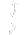
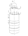
本発明の一実施例では、チップ表面のより均一な冷却のため、チップ表面に対する流体の層流をもたらす段階的形状を有する洗浄チップを有する屈曲可能なカテーテルを提供する。図1に示すように、カテーテル10は、近位、遠位端を有する先細のカテーテル本体12と、カテーテル本体12の遠位端のチップ部14と、カテーテル本体12の近位端の制御ハンドル16とを備えている。
In one embodiment of the present invention, a bendable catheter is provided having a cleaning tip having a stepped shape that provides laminar flow of fluid to the tip surface for more uniform cooling of the tip surface. As shown in FIG. 1, the
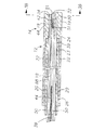
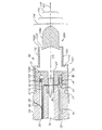
図1,2を参照すると、カテーテル本体12は単一の軸方向ないし中心的な中央ルーメン18を有する先細の管状構造体を備えている。カテーテル本体12はフレキシブル、即ち曲げ可能であるが、実質的にその長さに沿った圧縮性はない。カテーテル本体12はどのような適切な構造でもどのような適切な材料でもよい。現在、好適な構成は、ポリウレタンないしピーバックスからできた外壁22を備えている。外壁22は埋め込み式でブレード式のメッシュないしステンレススチールなどを備え、カテーテル本体12のねじれ剛性を増大しているので、制御ハンドル16を回転したとき、カテーテル10のチップ部14はそれに従って回転する。
Referring to FIGS. 1 and 2, the
カテーテル本体12の中央ルーメン18を通して延長しているのは、リード線、洗浄/輸注管、内部をプルワイヤプルワイヤ42が通る圧縮コイル44である。単一ルーメンカテーテル体はカテーテルを回転したときに優れたチップの制御ができることが分かったので、多ルーメン体よりも単一ルーメン体のほうが好ましい。圧縮コイルに囲まれた単一ルーメン体により、リード線、輸注管、プルワイヤはカテーテル本体内で自由に浮く。そのようなワイヤや管が多ルーメンで制限されるならば、ハンドルを回転したときにエネルギーを蓄えがちであり、例えばハンドルを放したときに逆回転しがちとなり、あるいは曲線の周りで曲げるとはじきかえり、そのどちらも望ましくない性能特性である。
Extending through the
カテーテル本体12の外径は重要ではないが、好適には約8フレンチ以下、より好適には7フレンチ以下である。同様に外壁22の厚さも重要ではないが、中央ルーメン18がリード線、プルワイヤ、洗浄/輸注管やどのようなワイヤ、ケーブル、管でも対応できる十分薄い厚さとする。外壁22の内面は、ポリイミドやナイロンなど、どのような適切な材料からでも作ることのできる強化チューブ20で裏打ちできる。強化チューブ20は、ブレード化した外壁22と共に、カテーテルと壁の厚さを最小にすると同時にねじれの安定性の改善をもたらし、それにより中央ルーメン18の径を最大にする。強化チューブ20の外径は外壁22の内径とほぼ同じか、わずかに小さい。ポリイミドチューブが、非常に良好な剛性を持ちながら非常に薄い壁にすることができるので、強化チューブ20には好ましい。
The outer diameter of the
一実施例では、カテーテルは、外壁22の直径が約0.約090インチから約0.94インチで、内径が約0.061インチから0.065インチで、ポリイミドの強化チューブ20は約0.060インチから約0.064インチの外径で、約0.051インチから0.056インチの内径を有する。
In one embodiment, the catheter has an
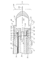
図3,3A、3Bに示すように、チップ部14はチップ電極36と管19の短部を備えている。管19は好適にはカテーテル本体12よりもフレキシブルな適切な非毒性の材料で作る。管19の現在の好適な材料は、ブレード式のポリウレタン、即ち埋め込み式のメッシュまたはブレード式のステンレススチールを備えたポリウレタンである。チップ部14の外径は、カテーテル本体12の外径と同様に、約8フレンチ以上でないことが好ましく、より好適には7フレンチ以下である。ルーメンのサイズは重要ではない。一実施例では、チップ部14は約7フレンチ(0.092インチ)の直径と複式ルーメンを有している。例示した実施例で、第1のルーメン30と第2のルーメン32は全般にほぼ同じサイズで、各々約0,020インチから0.024インチの直径で好適には0.022インチの直径を持ち、第3のルーメン34は約0.032インチから約0.0リング電極38インチで、好適には0.036インチのわずかに大きな直径を持つ。
As shown in FIGS. 3, 3 </ b> A and 3 </ b> B, the
図2にカテーテル本体12をチップ部14に取り付ける手段を示す。チップ部14の近位端は、カテーテル本体12の外壁22の内面を受ける外周ノッチ24を備える。チップ部14とカテーテル本体12は接着材などで付着する。しかしチップ部14とカテーテル本体12を付着する前に、強化管20をカテーテル本体12に挿入する。強化管20の遠位端は、ポリウレタン接着材などで接着材結合部23を形成することでカテーテル本体12の遠位端近くに固着させる。好適には例えば3mmの小さな距離をカテーテル本体12の遠位端と強化管20の遠位端の間に設けて、カテーテル本体12がチップ部14のノッチ24を受けるルームを可能にする。強化管20の近位端に力を加え、そして強化管20が圧縮下にあると、第1の接着材結合部(図示せず)が速乾接着材により強化管20と接着材結合部23の間に作られる。その後、外壁22を強化管20の近位端と外壁22の間に、例えばポリウレタンのような乾きは遅いが強力な接着材を使って形成する。
FIG. 2 shows a means for attaching the
所望により、強化チューブの遠位端とチップ部の近位端間のカテーテル本体内にスペーサを配置することもできる。スペーサによりカテーテル本体とチップ部間の接合部の柔軟性の転移がもたらされ、それによりこの接合部は折り曲げたりよじらせたりすることなくスムーズに曲がる。 If desired, a spacer can be placed in the catheter body between the distal end of the stiffening tube and the proximal end of the tip section. The spacer provides a transition in the flexibility of the joint between the catheter body and the tip so that the joint bends smoothly without bending or twisting.
図3,3Aを参照すると、本発明によると、チップ電極36はその近位、遠位端の間に段98を備えた段形状を有している。段形状によりチップ電極の外面に対する洗浄ないし冷却液の層流(ないし少なくとも乱流や渦流を最小限にする)を可能にする。図3,3Aに例示した実施例では、チップ電極36’は長軸100と、長軸100に対して全般的に鉛直な環状面102と、長軸100に沿って環状面102から遠位的に伸びている円筒面104とを有している。環状面102は、円筒面104の径110よりも大きな径108を有し、2つの表面102と円筒面104は長軸100について同軸となっている。
Referring to FIGS. 3 and 3A, according to the present invention, the
複数の開口部112が環状面102にその円周にわたり形成されていて、流体がチップ電極36’のプラグ118から環状面102に流れ、続けて円筒面104の上に層流の形で流れるようにする。流体をチップ電極の外面に平行な方向に流れるように導くため角度をつけた開口部112を設けることで、外面のより均一な冷却が可能となる。従って流体は円筒面104に対して、全般的に均一な厚さでシート状に流れ、あるとすればわずかな乱流だけの流体のブランケットないし層により円筒面104を被うことができる。そのような層流により、円筒面104のより均一な冷却が都合よく容易になる。
A plurality of
図3に例示した実施例では、長軸100について全般に同サイズかつ同形で、同角度の8つの開口部がある。開口部の位置、大きさ、構成は、所望により変えられることは当業者には理解されよう。複数の開口部は、約2から12、好適には約4から10の範囲で、より好適には約8とすることができる。
In the embodiment illustrated in FIG. 3, there are eight openings that are generally the same size, shape and angle for the
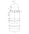
図4,4Aに示す別の実施例では、チップ電極36”は、円筒面104から遠位的に伸びた第2の外環面102Aと、第2の外環面102Aから遠位的に伸びた円筒面104Aを設けることで、2段階の形状(段98と98A)を有している。例示した実施例では、面102、102A、104、104Aは、長軸100について全て互いに同軸である。第2の外環面102Aの直径は一般に円筒面104の径110と等しく、円筒面104Aのシェル116は径110、108よりも小さい。
In another embodiment shown in FIGS. 4 and 4A, the
したがって、チップ電極の層流を可能にする各段98、98Aは、大径を有する外環面と、小径を有する遠位外周面の直列的な組み合わせから形成される。そして1つ以上の層流を可能にする段がある場合は、外周面が2つの外環面を接続するか、外環面が2つの外周面を接続する。変形例に関係なく、大部分の遠位外周面は先細りし、そうでなければその遠位端でチップ電極36の非外傷性の遠位端を形成する。
Accordingly, each
複数の開口部112Aが第2の外環面102Aにその円周にわたり形成されていて、流体がプラグ118から第2の外環面102Aに流れ、続けて円筒面104A上に層流の形で流れるようにする。図4Aの例示した実施例のチップ電極36”は開口部112と放射状に整列するが、開口部112と112Aは複数性、大きさ、形状、構成に関して同一である必要はないことを当業者は理解しよう。
A plurality of
チップ電極36’、36”の適切な実施例では、プラグ118内に形成された流体通路120へ第3のルーメン34から伸びた第2の注入管セグメント89によりチップ電極への架橋として第3のルーメン34により供給されるチャンバ118を共に限定するシェル116とプラグ118を有している。シェルとプラグで形成されたプラグ118はチップ電極内の流体通路の使用を避けるあるいは少なくとも最小限にし、それにより上述のように層流の形で流体の流れを促進する。
In a suitable embodiment of the
例示した実施例では、シェル116の外面は上述の環状面と円筒面を含み、さらに環状面102の近位である円筒面104Bを含む。円筒面104Bの径は一般に径108と管19の径に等しい。そのため、チップ電極36を管19に取り付ける手段を図3Aと図4Aに例示する。シェル116はプラグ118の近位端を近位的に越えて延長し、外周ノッチ27が受ける内周面を形成する。管とシェル116は接着材その他で付着させる。
In the illustrated embodiment, the outer surface of the
チップ電極の内部チャンバ118は密閉し、部分的にプラグ118により充たす。シェルとプラグを用いた適切な製造方法は、米国特許出願番号11/058,434号に記載されており、その開示全体を参照として本明細書に組み込む。本発明では、シェルとプラグを含むチップ電極は、例えばプラチナ―イリジウム・バー(プラチナ:90%、イリジウム:10%)など、どのような適切な材料からでも作ることができる。シェルは外面をミル加工して段状にし、内部をドリル加工してチャンバ118を形成する、立体的な円筒棒ないしバーから形成できる。開口部112,112Aはシェルの環状面102、第2の外環面102Aを穴あけし、好適にはプラグ118をシェル116に挿入する前にプラグ118の加工くずを清掃する。
The
チップ電極36はリード線40に接続する。リード線40はチップ部14(図3C)の第1のルーメン30、カテーテル本体12(図2)の中央ルーメン18、制御ハンドル16(図6)を通過して延長し、適切なモニタ(図示せず)に接続される入力ジャック(図示せず)内のその近位端で終わる。カテーテル本体12の中央ルーメン18、制御ハンドル16、チップ部14の近位端を延長するリード線40の一部は、好適にはポリイミドの、どのような適切な材料でも作製できる保護シース39内で包囲することができる。保護シース39は第1のルーメン30内においてポリウレタンなどで接着することで、その遠位端でチップ部14の近位端に係止する。リード線40は、いずれか従来の手法でチップ電極36に取り付けられる。リード線40のチップ電極36への接続を、リード線40をプラグ118内の第1の穴33に溶接することで行なう。
The
1つないし複数のリング電極38をチップ部14のフレキシブルな管19に配置できる。リング電極38の存在と数は所望により異なる。リード線40のリング電極38への接続は、好適には管19に小さな穴を作ることから行なう。そのような穴は、例えば管19に針を挿入し、針を十分加熱して常備穴を作ることができる。次にリード線40をマイクロフックなどを使って、該穴から引き抜く。次にリード線40の端部のコーティングを剥がし、リング電極38の下部に半田付けないし溶接し、次に穴を通して位置につけ、所定位置においてポリウレタン接着材などで固定する。
One or
温度感知手段をチップ電極36用に設けることができる。例えば熱電対やサーミスタなどの従来のどのような温度感知手段でも使用できる。図3,4を参照して、チップ電極36の好適な温度感知手段はワイヤ対で形成された熱電対から構成される。ワイヤ対の1本のワイヤは、例えば「40」番の銅線41である。ワイヤ対の他のワイヤはコンスタンタン・ワイヤ45で、ワイヤ対に支持と強度を与える。ワイヤ対のワイヤ41,45は、それらが接触し共にねじられ、例えばポリイミドのプラスチック管43で被われ、エポキシで被われた遠位端を除き、互いから電気的に遊離されている。次にプラスチック管43を、チップ電極36のプラグ118に形成されためくら穴31にポリウレタン接着材などで取り付ける。ワイヤ41,45はチップ部14の第1のルーメン30を通過して延長している。カテーテル本体12内では、ワイヤ41と45はリード線40と共に保護シース39を通過して延長する。ワイヤ41,45は次に制御ハンドル16を通り、温度モニタ(図示せず)へ接続可能なコネクタ(図示せず)に延長している。代わりに温度感知手段をサーミスタとすることができる。本発明で使用する適切なサーミスタは、サーモメトリック社(ニュージャージ)から販売されている型番AB6N2-GC14KA143E/37Cである。
Temperature sensing means can be provided for the
プルワイヤ42は、近位端が制御ハンドル16に係止され、遠位端がチップ部14に係止されたカテーテル本体12を通して伸びている。プルワイヤ42はステンレススチールやニチノールなどの任意の適切な材料で作製でき、好適にはテフロン(登録商標)などでコーティングする。コーティングによりプルワイヤ42に平滑性が生じる。好適にはプルワイヤ42は約0.006から約0.010インチの範囲の直径を持つ。
The
図2に示すように、圧縮コイル44は、プラーワイヤ42に対して周囲を取り囲んで、カテーテル本体12内部に位置づけられている。圧縮コイル44は、カテーテル本体12の近位端から先端部分14の近位端まで延びている。圧縮コイル44は、任意の適している金属、好ましくはステンレス鋼から作られる。圧縮コイル44は、それ自体にきつく巻かれて、柔軟性、すなわち、曲がるが圧縮に抵抗する性質を与える。圧縮コイル44の内径は、プラーワイヤ42の直径よりわずかに大きいことが好ましい。プラーワイヤ42にテフロン(登録商標)コーティングをすることにより、プラーワイヤ42は、圧縮コイル44内部で自由にスライドできる。所望ならば、リード線40が保護シース39によって取り囲まれていない場合、圧縮コイル44の外表面は、圧縮コイル44とカテーテル本体12内部のいずれの他のワイヤとの間の接触を防ぐため、例えばポリイミド製チューブの、柔軟な非伝導性シース、によって覆われていることができる。
As shown in FIG. 2, the
圧縮コイル44は、圧縮コイル44の近位端で、カテーテル本体12内の強化チューブ20の近位端に、接着継ぎ手50によって固定され、圧縮コイル44の遠位端で先端部分14に、接着継ぎ手51によって固定されている。接着継ぎ手50および接着継ぎ手51の両方は、ポリウレタン接着剤などを含むことが好ましい。接着剤は、カテーテル本体12の外表面と中央内腔18との間に作られた孔を通して、シリンジなどの手段によって塗布されてよい。そのような孔は、例えば、カテーテル本体12の外壁部22および強化チューブ20を穿刺し、永久的な孔を形成するのに十分に加熱させられる、針等によって形成されうる。その後、接着剤は、その孔を通して、圧縮コイル44の外表面へ導入され、圧縮コイル44の周囲全体付近に接着継ぎ手を形成するために外周囲の周辺に運ばれる。
The
図3、図3B、および、図4を参照すると、プラーワイヤ42は先端部分14の第2内腔32中へ延びている。プラーワイヤ42は、プラーワイヤ42の遠位端で、プラグ118に形成されている第2の止まり孔33内部でチップ電極36に固定されている。チップ電極36内部のプラーワイヤ42を固定する方法は、金属チューブ46をプラーワイヤ42の遠位端にかしめ、止まり孔33内部の金属チューブ46にはんだづけすることによるのが好ましい。チップ電極36内部のプラーワイヤ42を固定することによって、追加の支持が提供され、チップ電極36がチューブ19から外れる可能性を減らすことができる。代替的に、プラーワイヤ42は、先端部分14の側面に取り付けられることができる。先端部分14の第2内腔32内部で、プラーワイヤ42は、先端部分が屈曲されたときに、プラーワイヤ42が先端部分14の壁の中へ食い込むことを防ぐ、プラスチック製の、好ましくはテフロン(登録商標)製のシース81を通って延びている。
With reference to FIGS. 3, 3B and 4, the
注入チューブが、チップ電極36を冷却するための、流体、例えば、食塩水を注入するためにカテーテル本体12内部に提供されている。注入チューブは、また、薬剤を注入するため、あるいは、組織または流体サンプルを収集するために、使用されうる。注入チューブは、任意の適する材料から作られてよく、ポリイミド製チューブから作られるのが好ましい。好ましい注入チューブは、約8.13mm(0.32インチ)〜約0.91mm(0.036インチ)の外径を有し、約7.11mm(0.28インチ)〜約0.81mm(0.032インチ)の内径を有する。
An infusion tube is provided within the
図1、図2、および、図3を参照すると、第1注入チューブセグメント88は、カテーテル本体12の中央内腔18を通って延び、先端部分14の第3内腔34の近位端で終端している。第1注入チューブセグメント88の遠位端は、ポリウレタン接着剤などによって第3内腔34に固定されている。第1注入チューブ部分88の近位端は、制御ハンドル16を通って延び、制御ハンドルの近位側の位置のルアーハブ90などの中で終端している。
With reference to FIGS. 1, 2, and 3, the first
図3、および図4を参照すると、第2の注入チューブセグメント89が、第3の内腔34の遠位端部に設けられ、先端電極36の流体通路120内に延びている。第2の注入チューブセグメント89は、第3の内腔34および流体通路120内で、ポリウレタン接着剤などによって固定される。第2の注入チューブセグメント89は、プラーワイヤ42と同様に、先端電極に付加的な支持を与える。実際には、流体が、ルアーハブ90を通って第1の注入チューブセグメント88内に注入され、第1の注入チューブセグメント88、第3の内腔34、第2の注入チューブセグメント89を通って、先端電極36の流体通路120内に流れ込み、先端電極36の潅流開口部(irrigation openings)112、112Aから流れ出る。本発明によると、この潅流開口部112、112Aは、潅流用流体と先端電極36の表面との間の表面接触を増加させるようにして、先端電極36を横切って抜け出る潅流用流体を導くことによって、先端電極36の表面の効果的な潅流に備えるものである。先端電極36が潅流されると、RF電流の強さは、もはや界面温度(interface temperature)によって制限される必要はなく、したがって、電流を増加させることが可能となる。この結果、より大きく、より球状になる傾向を有する損傷部が生じる。
With reference to FIGS. 3 and 4, a second
図5を参照すると、結果として先端部分14の偏向を生じさせる、カテーテル本体12に対するプラーワイヤ42の長さ方向の動きが、制御ハンドル16の適切な操作によって達成される。図5に示すように、制御ハンドル16の遠位端部は、プラーワイヤ42を操作するために、親指制御部56を備えたピストン54を含む。カテーテル本体12の近位端部は、収縮スリーブ(shrink sleeve)28によってピストン54に接続されている。
Referring to FIG. 5, the longitudinal movement of the
プラーワイヤ42、リードワイヤ40、熱電対ワイヤ41、45、および第1の注入チューブセグメント88は、ピストン54内を通って延びる。プラーワイヤ42は、ピストン54の近位に位置する固定ピン57に固定されている。制御ハンドル16内では、リードワイヤ40、および熱電対ワイヤ41、45が保護シース39内にある。ピストン54内では、第1の注入チューブセグメント88が、上記の、サイドアーム94と同様、好ましくはポリウレタンで作られた、別の保護シース91内に延びている。保護シース39、91は、好ましくはポリウレタン接着剤などによって、接着接合部53でピストン54に固定され、ピストン54がプラーワイヤ42を操作するために調節されたときに、第1の注入チューブセグメント88、リードワイヤ40、および熱電対ワイヤ41、45が破損しないように、これら第1の注入チューブセグメント88、リードワイヤ40、および熱電対ワイヤ41、45が、制御ハンドル16内で長さ方向に動くことを可能にする。ピストン54内では、プラーワイヤ42が、好ましくはポリイミドチューブである移送チューブ(transfer tube)27を通って延び、プラーワイヤが接着接合部53の近くで長さ方向に動くことを可能にしている。
ピストン54は、制御ハンドルのバレル55内に配置されている。バレル55は、概して、ピストン54を受け入れるためのピストンチャンバを有する中実体である。3つの縦穴58、59、60、および固定ピン57を受け入れるための横穴が、ピストンチャンバから近位側に延びている。第2の縦穴59は、横穴と連通している。保護シース91内の第1の注入チューブセグメント88は、第1の縦穴58を通って延びている。プラーワイヤ42は、第2の縦穴59を通って延び、横穴で固定ピン57に固定される。保護シース39内の熱電対ワイヤ41、45、およびリードワイヤ40は、第3の縦穴60を通って延びる。縦穴58、59、60の遠位端部と、ピストン54の近位端部との間で、チャンバ62は、第1の注入チューブセグメント88の望ましくない屈曲を避けるため、追加の空間を提供する。この空間は、少なくとも約12.70mm(0.50インチ)の長さ、より好ましくは約15.24mm(約0.60インチ)〜約22.86mm(約0.90インチ)の長さを有することが好ましい。
The piston 54 is located in the
カテーテルは、先端電極36の近くに電磁センサを保有するように構成することができる。電磁センサケーブルは、チューブ19の第1の内腔30、または、もしあれば第4の内腔、およびカテーテル本体の中央内腔18を通って、制御ハンドル16内に延びることができる。電磁センサケーブルは、導管コード(umbilical cord)内の制御ハンドル16の近位端部から回路基板を収容するセンサ制御モジュールへ延出してもよい。あるいは、回路基板は、制御ハンドル16内に収容されてもよい。電磁センサケーブルは、プラスチックで保護されたシース内に入れられた複数のワイヤを含むことができる。センサ制御モジュールでは、電磁センサケーブルのワイヤが回路基板に接続されている。回路基板は、電磁センサから受信した信号を増幅し、センサ制御モジュールの近位端部のセンサコネクタによって、この信号をコンピュータが理解可能な形でコンピュータに送信する。また、カテーテルは、1回の使用のためにのみ設計されているので、回路基板は、好ましくはカテーテル使用後約24時間で回路基板をシャットダウンするEPROMチップを収容する。これにより、カテーテル、または少なくとも電磁センサが2回使用されることを防ぐ。好ましい電磁マッピングセンサは、約6mm〜約7mmの長さ、および約1.3mmの直径を有する。
The catheter can be configured to carry an electromagnetic sensor near the
〔実施の態様〕
(1)潅流切除カテーテルにおいて、
カテーテル本体と、
潅流先端電極を有する前記カテーテル本体の遠位側に位置する先端部分であって、
長さ方向軸、
前記長さ方向軸に対して概ね垂直な外側リング表面、
前記長さ方向軸に沿って前記外側リング表面から遠位に延びている外側円柱状表面、および、
流体を前記先端電極の内部を通して、前記外側円柱状表面にわたって層流状態で流すように、前記リング表面に形成された開口部、
を有する、先端部分と、
を具備する、潅流切除カテーテル。
(2)実施態様1記載の潅流切除カテーテルにおいて、
前記開口部は、流体の流れ方向を提供するように角度付けられており、この方向は、前記外側円柱状表面に対して概ね平行である、潅流切除カテーテル。
(3)実施態様1記載の潅流切除カテーテルにおいて、
前記外側円柱状表面は、長さ方向軸、および、各開口部が概ね平行となる軸、を有する、潅流切除カテーテル。
(4)実施態様1記載の潅流切除カテーテルにおいて、
前記開口部は、概ね等しい大きさを有し、前記長さ方向軸周りに等角度で位置する、潅流切除カテーテル。
(5)潅流切除カテーテルにおいて、
カテーテル本体と、
潅流先端電極を有する前記カテーテル本体の遠位側に位置する先端部分であって、
前記潅流先端電極は、
長さ方向軸、
前記長さ方向軸に対して概ね垂直な第1の外側リング表面、
前記長さ方向軸に沿って前記第1の外側リング表面から遠位に延びている第1の外側円柱状表面、
前記長さ方向軸に対して概ね垂直であり、前記第1の外側円柱状表面から遠位に延びている、第2の外側リング表面、
前記第2の外側リング表面から遠位に延びている第2の外側円柱状表面、および、
流体を前記先端電極の内部を通して、前記外側円柱状表面にわたって層流状態で流すように、前記リング表面に設けられた、流体のための開口部、
を備えている、
先端部分と、
を具備する、潅流切除カテーテル。
(6)組織を切除するための潅流カテーテルにおいて、
外壁部、近位端、遠位端、および、内部を通って延びる少なくとも1つの内腔、を有するカテーテル本体と、
近位端、遠位端、および内部を通る少なくとも1つの内腔、を有する可撓性チューブのセグメントを備える先端部分であって、前記先端部分の前記近位端は、前記カテーテル本体の前記遠位端に固定して取り付けられている、先端部分と、
近位端、遠位端、および長さ方向軸、を有する先端電極であって、
前記先端電極の前記近位端は、前記先端部分の前記遠位端に固定して取り付けられており、
前記先端電極は、
大径を有する近位外側リング表面、および小径を有する遠位外側リング表面であって、前記第1および第2のリング表面は、前記長さ方向軸に対して概ね垂直である、近位外側および遠位外側リング表面、
前記第1および第2の外側リング表面に接合している第1の外側円柱状表面、
前記遠位外側リング表面から遠位に延びている第2の外側円柱状表面であって、前記第1の外側円柱状表面の直径よりも小さい直径を有する、第2の外側円柱状表面、ならびに、
流体を前記先端電極の内部を通して、前記外側円柱状表面にわたって層流状態で流すように、前記外側リング表面に形成された開口部、
を備えている、
先端電極と、
を具備する、潅流カテーテル。
(7)実施態様6記載の潅流カテーテルにおいて、
前記第2の外側円柱状表面の遠位端は、前記先端電極の非外傷性遠位端を形成するように細くなっている、潅流カテーテル。
(8)実施態様6記載の潅流カテーテルにおいて、
前記カテーテル本体の前記近位端に設けられた制御ハンドル、
をさらに含む、潅流カテーテル。
(9)実施態様6記載の潅流カテーテルにおいて、
前記先端部分を偏向させるための偏向手段、
をさらに含む、潅流カテーテル。
(10)実施態様6記載の潅流カテーテルにおいて、
前記先端電極は、シェル、およびプラグ、を備えている、潅流カテーテル。
(11)実施態様9記載の潅流カテーテルにおいて、
前記偏向手段は、近位端、および遠位端、を有するプラーワイヤを備えており、
前記プラーワイヤは、前記制御ハンドルから前記カテーテル本体を通って、前記先端部分の内腔内へと延びており、これにより、前記制御ハンドルの操作が前記プラーワイヤを動かし、前記先端部分の偏向が生じる、
潅流カテーテル。
(12)実施態様6記載の潅流カテーテルにおいて、
前記先端電極に設置された温度検知手段、
をさらに含み、
前記温度検知手段は、熱電対を備えている、
潅流カテーテル。
(13)実施態様6記載の潅流カテーテルにおいて、
前記先端電極に設置されるか、または前記先端電極の近傍に設置された電磁マッピングセンサであって、前記電磁マッピングセンサの位置を示す電気信号を生成する、電磁マッピングセンサ、
をさらに含む、潅流カテーテル。
Embodiment
(1) In a perfusion ablation catheter,
A catheter body;
A tip portion located distally of the catheter body having a perfusion tip electrode,
Longitudinal axis,
An outer ring surface generally perpendicular to the longitudinal axis;
An outer cylindrical surface extending distally from the outer ring surface along the longitudinal axis; and
An opening formed in the ring surface to allow fluid to flow in a laminar flow through the interior of the tip electrode and across the outer cylindrical surface;
Having a tip portion;
A perfusion ablation catheter comprising:
(2) In the perfusion ablation catheter according to embodiment 1,
The perfusion ablation catheter, wherein the opening is angled to provide a fluid flow direction that is generally parallel to the outer cylindrical surface.
(3) In the perfusion ablation catheter according to embodiment 1,
The outer cylindrical surface has a longitudinal axis and an axis in which each opening is generally parallel.
(4) In the perfusion ablation catheter according to embodiment 1,
The perfusion ablation catheter, wherein the openings have approximately equal sizes and are equiangularly located about the longitudinal axis.
(5) In the perfusion ablation catheter,
A catheter body;
A tip portion located distally of the catheter body having a perfusion tip electrode,
The perfusion tip electrode is
Longitudinal axis,
A first outer ring surface generally perpendicular to the longitudinal axis;
A first outer cylindrical surface extending distally from the first outer ring surface along the longitudinal axis;
A second outer ring surface that is generally perpendicular to the longitudinal axis and extends distally from the first outer cylindrical surface;
A second outer cylindrical surface extending distally from the second outer ring surface; and
An opening for the fluid provided in the ring surface to allow fluid to flow in a laminar flow through the interior of the tip electrode and across the outer cylindrical surface;
With
A tip portion;
A perfusion ablation catheter comprising:
(6) In a perfusion catheter for excising tissue,
A catheter body having an outer wall, a proximal end, a distal end, and at least one lumen extending therethrough;
A tip portion comprising a segment of a flexible tube having a proximal end, a distal end, and at least one lumen therethrough, wherein the proximal end of the tip portion is the distal end of the catheter body. A tip portion fixedly attached to the end, and
A tip electrode having a proximal end, a distal end, and a longitudinal axis,
The proximal end of the tip electrode is fixedly attached to the distal end of the tip portion;
The tip electrode is
A proximal outer ring surface having a large diameter and a distal outer ring surface having a small diameter, wherein the first and second ring surfaces are generally perpendicular to the longitudinal axis And distal outer ring surface,
A first outer cylindrical surface joined to the first and second outer ring surfaces;
A second outer cylindrical surface extending distally from the distal outer ring surface, the second outer cylindrical surface having a diameter less than the diameter of the first outer cylindrical surface; and ,
An opening formed in the outer ring surface for flowing fluid in a laminar flow through the interior of the tip electrode and across the outer cylindrical surface;
With
A tip electrode;
A perfusion catheter comprising:
(7) In the perfusion catheter according to embodiment 6,
A perfusion catheter, wherein a distal end of the second outer cylindrical surface is tapered to form an atraumatic distal end of the tip electrode.
(8) In the perfusion catheter according to embodiment 6,
A control handle provided at the proximal end of the catheter body;
A perfusion catheter.
(9) In the perfusion catheter according to embodiment 6,
Deflection means for deflecting the tip portion;
A perfusion catheter.
(10) In the perfusion catheter according to embodiment 6,
The tip electrode comprises a shell and a plug, a perfusion catheter.
(11) In the perfusion catheter according to embodiment 9,
The deflection means comprises a puller wire having a proximal end and a distal end;
The puller wire extends from the control handle, through the catheter body, and into the lumen of the tip portion, so that manipulation of the control handle moves the puller wire, resulting in deflection of the tip portion.
Perfusion catheter.
(12) In the perfusion catheter according to embodiment 6,
Temperature detection means installed on the tip electrode;
Further including
The temperature detection means includes a thermocouple,
Perfusion catheter.
(13) In the perfusion catheter according to embodiment 6,
An electromagnetic mapping sensor installed on the tip electrode or in the vicinity of the tip electrode, wherein the electromagnetic mapping sensor generates an electrical signal indicating a position of the electromagnetic mapping sensor;
A perfusion catheter.
本発明の好ましい実施形態についての上記説明は、解説および説明の目的で提示されている。本発明を包括的なものとする、または開示された正確な形態に制限することは意図されていない。本発明が属する分野および技術に熟練する者であれば、本発明の原理、精神、および範囲から意義を持って逸脱することなく、説明された構造における改造、および変更を行うことができることを理解するであろう。本願の範囲は、この詳細な説明によって制限されるのではなく、特許請求の範囲、および特許請求の範囲の等価物によって制限されることが意図されている。 The foregoing descriptions of preferred embodiments of the present invention have been presented for purposes of illustration and description. It is not intended to be exhaustive or to limit the invention to the precise form disclosed. Those skilled in the art and technology to which the present invention pertains understand that modifications and changes can be made in the structure described without departing from the principles, spirit and scope of the present invention in a meaningful manner. Will do. It is intended that the scope of the application be limited not by this detailed description, but rather by the claims and their equivalents.
Claims (9)
カテーテル本体と、
潅流先端電極を有する前記カテーテル本体の遠位側に位置する先端部分であって、
前記潅流先端電極は、
長さ方向軸、
前記長さ方向軸に対して概ね垂直な第1の外側リング表面、
前記長さ方向軸に沿って前記第1の外側リング表面から遠位に延びている第1の外側円柱状表面、
前記第1の外側円柱状表面の先端部に接合されており、前記長さ方向軸に対して概ね垂直な第2の外側リング表面、
前記第2の外側リング表面から遠位に延びている第2の外側円柱状表面、および、
流体を前記先端電極の内部を通して、前記第1および第2の外側円柱状表面にわたって層流状態で流すように、前記第1および第2の外側リング表面に設けられた、流体のための開口部、
を有している、
先端部分と、
を有し、
前記第1および第2の外側リング表面に設けられた前記開口部は、前記第1および第2の外側円柱状表面を取り囲むように前記第1および第2の外側リング表面にそれぞれ配されている、
潅流切除カテーテル。 In perfusion ablation catheters,
A catheter body;
A tip portion located distally of the catheter body having a perfusion tip electrode,
The perfusion tip electrode is
Longitudinal axis,
A first outer ring surface generally perpendicular to the longitudinal axis;
A first outer cylindrical surface extending distally from the first outer ring surface along the longitudinal axis;
A second outer ring surface joined to a tip of the first outer cylindrical surface and generally perpendicular to the longitudinal axis;
A second outer cylindrical surface extending distally from the second outer ring surface; and
An opening for the fluid provided in the first and second outer ring surfaces to cause fluid to flow in a laminar flow through the interior of the tip electrode and across the first and second outer cylindrical surfaces ,
have,
A tip portion;
I have a,
The openings provided in the first and second outer ring surfaces are respectively arranged on the first and second outer ring surfaces so as to surround the first and second outer cylindrical surfaces. ,
Perfusion ablation catheter.
外壁部、近位端、遠位端、および、内部を通って延びる少なくとも1つの内腔、を有するカテーテル本体と、
近位端、遠位端、および内部を通る少なくとも1つの内腔、を有する可撓性チューブのセグメントを備える先端部分であって、前記先端部分の前記近位端は、前記カテーテル本体の前記遠位端に固定して取り付けられている、先端部分と、
近位端、遠位端、および長さ方向軸、を有する先端電極であって、
前記先端電極の前記近位端は、前記先端部分の前記遠位端に固定して取り付けられており、
前記先端電極は、
近位外側リング表面、および遠位外側リング表面であって、前記近位外側リング表面は前記遠位外側リング表面の直径よりも大きな直径を有しており、前記近位および遠位外側リング表面は、前記長さ方向軸に対して概ね垂直である、近位および遠位外側リング表面、
前記近位および遠位外側リング表面に接合している第1の外側円柱状表面、
前記遠位外側リング表面から遠位に延びている第2の外側円柱状表面であって、前記第1の外側円柱状表面の直径よりも小さい直径を有する、第2の外側円柱状表面、ならびに、
流体を前記先端電極の内部を通して、前記第1および第2の外側円柱状表面にわたって層流状態で流すように、前記近位および遠位外側リング表面に形成された開口部、
を有している、
先端電極と、
を有し、
前記近位および遠位外側リング表面に設けられた前記開口部は、前記第1および第2の外側円柱状表面を取り囲むように前記近位および遠位外側リング表面にそれぞれ配されている、
潅流カテーテル。 In a perfusion catheter for excising tissue,
A catheter body having an outer wall, a proximal end, a distal end, and at least one lumen extending therethrough;
A tip portion comprising a segment of a flexible tube having a proximal end, a distal end, and at least one lumen therethrough, wherein the proximal end of the tip portion is the distal end of the catheter body. A tip portion fixedly attached to the end, and
A tip electrode having a proximal end, a distal end, and a longitudinal axis,
The proximal end of the tip electrode is fixedly attached to the distal end of the tip portion;
The tip electrode is
A proximal outer ring surface and a distal outer ring surface, wherein the proximal outer ring surface has a diameter greater than a diameter of the distal outer ring surface; Are proximal and distal outer ring surfaces that are generally perpendicular to the longitudinal axis;
A first outer cylindrical surface joined to the proximal and distal outer ring surfaces;
A second outer cylindrical surface extending distally from the distal outer ring surface, the second outer cylindrical surface having a diameter less than the diameter of the first outer cylindrical surface; and ,
Openings formed in the proximal and distal outer ring surfaces to allow fluid to flow through the interior of the tip electrode and over the first and second outer cylindrical surfaces in a laminar state;
have,
A tip electrode;
I have a,
The openings provided in the proximal and distal outer ring surfaces are respectively disposed in the proximal and distal outer ring surfaces to surround the first and second outer cylindrical surfaces;
Perfusion catheter.
前記第2の外側円柱状表面の遠位端は、前記先端電極の非外傷性遠位端を形成するように細くなっている、潅流カテーテル。 The perfusion catheter according to claim 2,
A perfusion catheter, wherein a distal end of the second outer cylindrical surface is tapered to form an atraumatic distal end of the tip electrode.
前記カテーテル本体の前記近位端に設けられた制御ハンドル、
をさらに含む、潅流カテーテル。 The perfusion catheter according to claim 2,
A control handle provided at the proximal end of the catheter body;
A perfusion catheter.
前記先端部分を偏向させるための偏向手段、
をさらに含む、潅流カテーテル。 The perfusion catheter according to claim 2,
Deflection means for deflecting the tip portion;
A perfusion catheter.
前記先端電極は、シェル、およびプラグ、を備えている、潅流カテーテル。 The perfusion catheter according to claim 2,
The tip electrode comprises a shell and a plug, a perfusion catheter.
前記偏向手段は、近位端、および遠位端、を有するプラーワイヤを備えており、
前記プラーワイヤは、前記制御ハンドルから前記カテーテル本体を通って、前記先端部分の内腔内へと延びており、これにより、前記制御ハンドルの操作が前記プラーワイヤを動かし、前記先端部分の偏向が生じる、
潅流カテーテル。 The perfusion catheter according to claim 5,
The deflection means comprises a puller wire having a proximal end and a distal end;
The puller wire extends from the control handle, through the catheter body, and into the lumen of the tip portion, so that manipulation of the control handle moves the puller wire, resulting in deflection of the tip portion.
Perfusion catheter.
前記先端電極に設置された温度検知手段、
をさらに含み、
前記温度検知手段は、熱電対を備えている、
潅流カテーテル。 The perfusion catheter according to claim 2,
Temperature detection means installed on the tip electrode;
Further including
The temperature detection means includes a thermocouple,
Perfusion catheter.
前記先端電極に設置されるか、または前記先端電極の近傍に設置された電磁マッピングセンサであって、前記電磁マッピングセンサの位置を示す電気信号を生成する、電磁マッピングセンサ、
をさらに含む、潅流カテーテル。 The perfusion catheter according to claim 2,
An electromagnetic mapping sensor installed on the tip electrode or in the vicinity of the tip electrode, wherein the electromagnetic mapping sensor generates an electrical signal indicating a position of the electromagnetic mapping sensor;
A perfusion catheter.
Applications Claiming Priority (2)
| Application Number | Priority Date | Filing Date | Title |
|---|---|---|---|
| US11/322,583 | 2005-12-30 | ||
| US11/322,583 US7628788B2 (en) | 2005-12-30 | 2005-12-30 | Ablation catheter with improved tip cooling |
Publications (2)
| Publication Number | Publication Date |
|---|---|
| JP2007181695A JP2007181695A (en) | 2007-07-19 |
| JP5259084B2 true JP5259084B2 (en) | 2013-08-07 |
Family
ID=37865686
Family Applications (1)
| Application Number | Title | Priority Date | Filing Date |
|---|---|---|---|
| JP2006355426A Active JP5259084B2 (en) | 2005-12-30 | 2006-12-28 | Ablation catheter with improved tip cooling |
Country Status (5)
| Country | Link |
|---|---|
| US (1) | US7628788B2 (en) |
| EP (1) | EP1803407B1 (en) |
| JP (1) | JP5259084B2 (en) |
| AT (1) | ATE489049T1 (en) |
| DE (1) | DE602006018416D1 (en) |
Families Citing this family (46)
| Publication number | Priority date | Publication date | Assignee | Title |
|---|---|---|---|---|
| US8109981B2 (en) | 2005-01-25 | 2012-02-07 | Valam Corporation | Optical therapies and devices |
| EP2066251B1 (en) | 2006-10-10 | 2017-05-03 | St. Jude Medical, Atrial Fibrillation Division, Inc. | Ablation electrode assembly with insulated distal outlet |
| US7914528B2 (en) * | 2006-12-29 | 2011-03-29 | St. Jude Medical, Atrial Fibrillation Division, Inc. | Ablation catheter tip for generating an angled flow |
| US9579148B2 (en) * | 2007-11-13 | 2017-02-28 | St. Jude Medical, Atrial Fibrillation Division, Inc. | Irrigated ablation electrode having recessed surface portions |
| US8128620B2 (en) * | 2007-11-13 | 2012-03-06 | St. Jude Medical, Atrial Fibrillation Division, Inc. | Irrigated ablation electrode having proximal direction flow |
| US8052684B2 (en) | 2007-11-30 | 2011-11-08 | St. Jude Medical, Atrial Fibrillation Division, Inc. | Irrigated ablation catheter having parallel external flow and proximally tapered electrode |
| US8221409B2 (en) * | 2007-12-21 | 2012-07-17 | St. Jude Medical, Atrial Fibrillation Division, Inc. | Thermally insulated irrigation catheter assembly |
| US8216225B2 (en) * | 2007-12-21 | 2012-07-10 | St. Jude Medical, Atrial Fibrillation Division, Inc. | Irrigated ablation electrode assembly having a polygonal electrode |
| US8273082B2 (en) | 2007-12-21 | 2012-09-25 | St. Jude Medical, Atrial Fibrillation Division, Inc. | Irrigated ablation catheter assembly having a flow member to create parallel external flow |
| US8974453B2 (en) * | 2008-12-02 | 2015-03-10 | St. Jude Medical, Atrial Fibrillation Division, Inc. | Irrigated ablation catheter having a flexible manifold |
| US9757189B2 (en) * | 2008-12-03 | 2017-09-12 | Biosense Webster, Inc. | Prevention of kinks in catheter irrigation tubes |
| US9629678B2 (en) * | 2008-12-30 | 2017-04-25 | St. Jude Medical, Atrial Fibrillation Division, Inc. | Controlled irrigated catheter ablation systems and methods thereof |
| US9226791B2 (en) | 2012-03-12 | 2016-01-05 | Advanced Cardiac Therapeutics, Inc. | Systems for temperature-controlled ablation using radiometric feedback |
| US8954161B2 (en) | 2012-06-01 | 2015-02-10 | Advanced Cardiac Therapeutics, Inc. | Systems and methods for radiometrically measuring temperature and detecting tissue contact prior to and during tissue ablation |
| US9277961B2 (en) | 2009-06-12 | 2016-03-08 | Advanced Cardiac Therapeutics, Inc. | Systems and methods of radiometrically determining a hot-spot temperature of tissue being treated |
| US8926605B2 (en) | 2012-02-07 | 2015-01-06 | Advanced Cardiac Therapeutics, Inc. | Systems and methods for radiometrically measuring temperature during tissue ablation |
| US20110028962A1 (en) * | 2009-07-31 | 2011-02-03 | Randell Werneth | Adjustable pulmonary vein ablation catheter |
| US9084610B2 (en) * | 2010-10-21 | 2015-07-21 | Medtronic Ardian Luxembourg S.A.R.L. | Catheter apparatuses, systems, and methods for renal neuromodulation |
| US8986303B2 (en) * | 2010-11-09 | 2015-03-24 | Biosense Webster, Inc. | Catheter with liquid-cooled control handle |
| US9192766B2 (en) | 2011-12-02 | 2015-11-24 | Medtronic Ardian Luxembourg S.A.R.L. | Renal neuromodulation methods and devices for treatment of polycystic kidney disease |
| JP5881229B2 (en) * | 2011-12-09 | 2016-03-09 | 日本ライフライン株式会社 | Electrode catheter |
| JP5867917B2 (en) * | 2011-12-09 | 2016-02-24 | 日本ライフライン株式会社 | Electrode catheter |
| WO2013134548A2 (en) | 2012-03-08 | 2013-09-12 | Medtronic Ardian Luxembourg S.A.R.L. | Ovarian neuromodulation and associated systems and methods |
| AU2013230774B2 (en) | 2012-03-08 | 2015-12-03 | Medtronic Af Luxembourg S.A.R.L. | Gastrointestinal neuromodulation and associated systems and methods |
| CN102813552B (en) * | 2012-08-10 | 2015-01-07 | 乐普(北京)医疗器械股份有限公司 | Fixing device for large-tip electrode in cold saline infusion ablation catheter |
| US9233225B2 (en) | 2012-11-10 | 2016-01-12 | Curvo Medical, Inc. | Coaxial bi-directional catheter |
| US9549666B2 (en) | 2012-11-10 | 2017-01-24 | Curvo Medical, Inc. | Coaxial micro-endoscope |
| US9044156B2 (en) * | 2012-12-28 | 2015-06-02 | Biosense Webster (Israel) Ltd. | Catheter with improved safety line for distal tip and related method |
| US20140276562A1 (en) * | 2013-03-14 | 2014-09-18 | Biosense Webster (Israel), Ltd. | Catheter with spray irrigation |
| JP6235116B2 (en) | 2013-03-15 | 2017-11-22 | ボストン サイエンティフィック サイムド,インコーポレイテッドBoston Scientific Scimed,Inc. | Open water ablation catheter with proximal cooling |
| WO2014151822A2 (en) * | 2013-03-15 | 2014-09-25 | Boston Scientific Scimed, Inc. | Open irrigated ablation catheter |
| US9339333B2 (en) * | 2013-12-24 | 2016-05-17 | Biosense Webster (Israel) Ltd. | Torsion reduction system |
| US10813686B2 (en) * | 2014-02-26 | 2020-10-27 | Medtronic Advanced Energy Llc | Electrosurgical cutting instrument |
| SG11201703943VA (en) | 2014-11-19 | 2017-06-29 | Advanced Cardiac Therapeutics Inc | Ablation devices, systems and methods of using a high-resolution electrode assembly |
| EP3220841B1 (en) | 2014-11-19 | 2023-01-25 | EPiX Therapeutics, Inc. | High-resolution mapping of tissue with pacing |
| EP3220844B1 (en) | 2014-11-19 | 2020-11-11 | EPiX Therapeutics, Inc. | Systems for high-resolution mapping of tissue |
| US9636164B2 (en) | 2015-03-25 | 2017-05-02 | Advanced Cardiac Therapeutics, Inc. | Contact sensing systems and methods |
| CA3017269A1 (en) | 2016-03-15 | 2017-09-21 | Epix Therapeutics, Inc. | Improved devices, systems and methods for irrigated ablation |
| KR20190062419A (en) | 2016-10-04 | 2019-06-05 | 아벤트, 인크. | The cooled RF probe |
| WO2018118823A1 (en) | 2016-12-19 | 2018-06-28 | Boston Scientific Scimed Inc. | Open-irrigated ablation catheter with proximal insert cooling |
| EP3614946B1 (en) | 2017-04-27 | 2024-03-20 | EPiX Therapeutics, Inc. | Determining nature of contact between catheter tip and tissue |
| PL3412234T3 (en) * | 2017-06-07 | 2023-03-06 | Erbe Elektromedizin Gmbh | MULTI-JET INSTRUMENT FOR ARGON PLASMA COAGULATION |
| WO2020190154A2 (en) * | 2019-03-21 | 2020-09-24 | Paul Weber | Apparatus and methods for minimally invasive dissection and modification of tissues |
| WO2022098932A1 (en) | 2020-11-09 | 2022-05-12 | Agile Devices, Inc. | Devices for steering catheters |
| EP4295886A4 (en) * | 2021-02-22 | 2024-12-25 | Kaneka Corporation | PUNCTURE DEVICE |
| EP4209188A1 (en) * | 2022-01-07 | 2023-07-12 | Erbe Elektromedizin GmbH | Plasma probe |
Family Cites Families (11)
| Publication number | Priority date | Publication date | Assignee | Title |
|---|---|---|---|---|
| US20020042612A1 (en) * | 1997-10-27 | 2002-04-11 | Hood Larry L. | Method and apparatus for modifications of visual acuity by thermal means |
| US5634921A (en) * | 1993-08-23 | 1997-06-03 | Hood; Larry | Method and apparatus for modifications of visual acuity by thermal means |
| US6120476A (en) * | 1997-12-01 | 2000-09-19 | Cordis Webster, Inc. | Irrigated tip catheter |
| US6298257B1 (en) | 1999-09-22 | 2001-10-02 | Sterotaxis, Inc. | Cardiac methods and system |
| DE10030111B4 (en) | 2000-06-19 | 2008-07-10 | Erbe Elektromedizin Gmbh | probe electrode |
| US6413256B1 (en) * | 2000-08-01 | 2002-07-02 | Csaba Truckai | Voltage threshold ablation method and apparatus |
| US20020198520A1 (en) * | 2001-06-20 | 2002-12-26 | Scimed Life Systems, Inc. | Irrigation sheath |
| US6611699B2 (en) * | 2001-06-28 | 2003-08-26 | Scimed Life Systems, Inc. | Catheter with an irrigated composite tip electrode |
| US6980843B2 (en) | 2003-05-21 | 2005-12-27 | Stereotaxis, Inc. | Electrophysiology catheter |
| FR2858398B1 (en) | 2003-07-30 | 2005-12-02 | Air Liquide | METHOD AND INSTALLATION FOR SUPPLYING AN AIR SEPARATION UNIT USING A GAS TURBINE |
| US8894642B2 (en) | 2004-05-17 | 2014-11-25 | Boston Scientific Scimed, Inc. | Irrigated catheter |
-
2005
- 2005-12-30 US US11/322,583 patent/US7628788B2/en active Active
-
2006
- 2006-12-28 JP JP2006355426A patent/JP5259084B2/en active Active
- 2006-12-29 AT AT06256632T patent/ATE489049T1/en not_active IP Right Cessation
- 2006-12-29 DE DE602006018416T patent/DE602006018416D1/en active Active
- 2006-12-29 EP EP06256632A patent/EP1803407B1/en active Active
Also Published As
| Publication number | Publication date |
|---|---|
| US20070156131A1 (en) | 2007-07-05 |
| DE602006018416D1 (en) | 2011-01-05 |
| EP1803407A1 (en) | 2007-07-04 |
| JP2007181695A (en) | 2007-07-19 |
| US7628788B2 (en) | 2009-12-08 |
| ATE489049T1 (en) | 2010-12-15 |
| EP1803407B1 (en) | 2010-11-24 |
Similar Documents
| Publication | Publication Date | Title |
|---|---|---|
| JP5259084B2 (en) | Ablation catheter with improved tip cooling | |
| AU2018253573B2 (en) | Irrigated catheter with fluid evacuation | |
| JP5052888B2 (en) | Injection molded perfusion tip electrode and catheter with injection molded perfusion tip electrode | |
| US8333762B2 (en) | Irrigated catheter with improved irrigation flow | |
| JP6153751B2 (en) | Catheter with composite construction | |
| CN103315806B (en) | The tessellating conduits with other tubular sites are protruded for mapping and ablation vein | |
| US10070919B2 (en) | Irrigant distribution system for electrodes | |
| US6852120B1 (en) | Irrigation probe for ablation during open heart surgery | |
| US8133220B2 (en) | Enhanced ablation and mapping catheter and method for treating atrial fibrillation | |
| US6171275B1 (en) | Irrigated split tip electrode catheter | |
| US20180207404A1 (en) | Deflectable catheter with a flexibly attached tip section | |
| US20040187875A1 (en) | Method and apparatus for altering conduction properties along pathways in the heart and in vessels in conductive communication with the heart. | |
| JP2003514635A (en) | Atrial circumcision loop with expandable pusher | |
| CN120204575A (en) | Flow diversion elements for catheters | |
| IL229293A (en) | Irrigated catheter with fluid evacuation |
Legal Events
| Date | Code | Title | Description |
|---|---|---|---|
| RD04 | Notification of resignation of power of attorney |
Free format text: JAPANESE INTERMEDIATE CODE: A7424 Effective date: 20071130 |
|
| RD04 | Notification of resignation of power of attorney |
Free format text: JAPANESE INTERMEDIATE CODE: A7424 Effective date: 20081017 |
|
| RD04 | Notification of resignation of power of attorney |
Free format text: JAPANESE INTERMEDIATE CODE: A7424 Effective date: 20081020 |
|
| A621 | Written request for application examination |
Free format text: JAPANESE INTERMEDIATE CODE: A621 Effective date: 20091002 |
|
| A977 | Report on retrieval |
Free format text: JAPANESE INTERMEDIATE CODE: A971007 Effective date: 20110922 |
|
| A131 | Notification of reasons for refusal |
Free format text: JAPANESE INTERMEDIATE CODE: A131 Effective date: 20110927 |
|
| A601 | Written request for extension of time |
Free format text: JAPANESE INTERMEDIATE CODE: A601 Effective date: 20111227 |
|
| A602 | Written permission of extension of time |
Free format text: JAPANESE INTERMEDIATE CODE: A602 Effective date: 20120105 |
|
| A601 | Written request for extension of time |
Free format text: JAPANESE INTERMEDIATE CODE: A601 Effective date: 20120127 |
|
| A602 | Written permission of extension of time |
Free format text: JAPANESE INTERMEDIATE CODE: A602 Effective date: 20120201 |
|
| A521 | Request for written amendment filed |
Free format text: JAPANESE INTERMEDIATE CODE: A523 Effective date: 20120222 |
|
| A131 | Notification of reasons for refusal |
Free format text: JAPANESE INTERMEDIATE CODE: A131 Effective date: 20120807 |
|
| A521 | Request for written amendment filed |
Free format text: JAPANESE INTERMEDIATE CODE: A523 Effective date: 20121016 |
|
| TRDD | Decision of grant or rejection written | ||
| A01 | Written decision to grant a patent or to grant a registration (utility model) |
Free format text: JAPANESE INTERMEDIATE CODE: A01 Effective date: 20130402 |
|
| A61 | First payment of annual fees (during grant procedure) |
Free format text: JAPANESE INTERMEDIATE CODE: A61 Effective date: 20130424 |
|
| FPAY | Renewal fee payment (event date is renewal date of database) |
Free format text: PAYMENT UNTIL: 20160502 Year of fee payment: 3 |
|
| R150 | Certificate of patent or registration of utility model |
Ref document number: 5259084 Country of ref document: JP Free format text: JAPANESE INTERMEDIATE CODE: R150 Free format text: JAPANESE INTERMEDIATE CODE: R150 |
|
| R250 | Receipt of annual fees |
Free format text: JAPANESE INTERMEDIATE CODE: R250 |
|
| R250 | Receipt of annual fees |
Free format text: JAPANESE INTERMEDIATE CODE: R250 |
|
| R250 | Receipt of annual fees |
Free format text: JAPANESE INTERMEDIATE CODE: R250 |
|
| R250 | Receipt of annual fees |
Free format text: JAPANESE INTERMEDIATE CODE: R250 |
|
| R250 | Receipt of annual fees |
Free format text: JAPANESE INTERMEDIATE CODE: R250 |
|
| R250 | Receipt of annual fees |
Free format text: JAPANESE INTERMEDIATE CODE: R250 |
|
| R250 | Receipt of annual fees |
Free format text: JAPANESE INTERMEDIATE CODE: R250 |
|
| R250 | Receipt of annual fees |
Free format text: JAPANESE INTERMEDIATE CODE: R250 |
|
| R250 | Receipt of annual fees |
Free format text: JAPANESE INTERMEDIATE CODE: R250 |
|
| R250 | Receipt of annual fees |
Free format text: JAPANESE INTERMEDIATE CODE: R250 |