JP5259014B2 - Method and system for managing a body area network using a coordinator device - Google Patents
Method and system for managing a body area network using a coordinator device Download PDFInfo
- Publication number
- JP5259014B2 JP5259014B2 JP2012508406A JP2012508406A JP5259014B2 JP 5259014 B2 JP5259014 B2 JP 5259014B2 JP 2012508406 A JP2012508406 A JP 2012508406A JP 2012508406 A JP2012508406 A JP 2012508406A JP 5259014 B2 JP5259014 B2 JP 5259014B2
- Authority
- JP
- Japan
- Prior art keywords
- signal
- coordinator
- security
- mics
- channel
- Prior art date
- Legal status (The legal status is an assumption and is not a legal conclusion. Google has not performed a legal analysis and makes no representation as to the accuracy of the status listed.)
- Expired - Fee Related
Links
Images


Classifications
-
- H—ELECTRICITY
- H04—ELECTRIC COMMUNICATION TECHNIQUE
- H04L—TRANSMISSION OF DIGITAL INFORMATION, e.g. TELEGRAPHIC COMMUNICATION
- H04L9/00—Cryptographic mechanisms or cryptographic arrangements for secret or secure communications; Network security protocols
- H04L9/32—Cryptographic mechanisms or cryptographic arrangements for secret or secure communications; Network security protocols including means for verifying the identity or authority of a user of the system or for message authentication, e.g. authorization, entity authentication, data integrity or data verification, non-repudiation, key authentication or verification of credentials
- H04L9/3271—Cryptographic mechanisms or cryptographic arrangements for secret or secure communications; Network security protocols including means for verifying the identity or authority of a user of the system or for message authentication, e.g. authorization, entity authentication, data integrity or data verification, non-repudiation, key authentication or verification of credentials using challenge-response
-
- H—ELECTRICITY
- H04—ELECTRIC COMMUNICATION TECHNIQUE
- H04B—TRANSMISSION
- H04B13/00—Transmission systems characterised by the medium used for transmission, not provided for in groups H04B3/00 - H04B11/00
- H04B13/02—Transmission systems in which the medium consists of the earth or a large mass of water thereon, e.g. earth telegraphy
-
- H—ELECTRICITY
- H04—ELECTRIC COMMUNICATION TECHNIQUE
- H04L—TRANSMISSION OF DIGITAL INFORMATION, e.g. TELEGRAPHIC COMMUNICATION
- H04L9/00—Cryptographic mechanisms or cryptographic arrangements for secret or secure communications; Network security protocols
- H04L9/08—Key distribution or management, e.g. generation, sharing or updating, of cryptographic keys or passwords
- H04L9/0816—Key establishment, i.e. cryptographic processes or cryptographic protocols whereby a shared secret becomes available to two or more parties, for subsequent use
- H04L9/0819—Key transport or distribution, i.e. key establishment techniques where one party creates or otherwise obtains a secret value, and securely transfers it to the other(s)
- H04L9/083—Key transport or distribution, i.e. key establishment techniques where one party creates or otherwise obtains a secret value, and securely transfers it to the other(s) involving central third party, e.g. key distribution center [KDC] or trusted third party [TTP]
- H04L9/0833—Key transport or distribution, i.e. key establishment techniques where one party creates or otherwise obtains a secret value, and securely transfers it to the other(s) involving central third party, e.g. key distribution center [KDC] or trusted third party [TTP] involving conference or group key
-
- H—ELECTRICITY
- H04—ELECTRIC COMMUNICATION TECHNIQUE
- H04L—TRANSMISSION OF DIGITAL INFORMATION, e.g. TELEGRAPHIC COMMUNICATION
- H04L9/00—Cryptographic mechanisms or cryptographic arrangements for secret or secure communications; Network security protocols
- H04L9/08—Key distribution or management, e.g. generation, sharing or updating, of cryptographic keys or passwords
- H04L9/0861—Generation of secret information including derivation or calculation of cryptographic keys or passwords
- H04L9/0866—Generation of secret information including derivation or calculation of cryptographic keys or passwords involving user or device identifiers, e.g. serial number, physical or biometrical information, DNA, hand-signature or measurable physical characteristics
-
- H—ELECTRICITY
- H04—ELECTRIC COMMUNICATION TECHNIQUE
- H04L—TRANSMISSION OF DIGITAL INFORMATION, e.g. TELEGRAPHIC COMMUNICATION
- H04L9/00—Cryptographic mechanisms or cryptographic arrangements for secret or secure communications; Network security protocols
- H04L9/14—Cryptographic mechanisms or cryptographic arrangements for secret or secure communications; Network security protocols using a plurality of keys or algorithms
-
- H—ELECTRICITY
- H04—ELECTRIC COMMUNICATION TECHNIQUE
- H04L—TRANSMISSION OF DIGITAL INFORMATION, e.g. TELEGRAPHIC COMMUNICATION
- H04L9/00—Cryptographic mechanisms or cryptographic arrangements for secret or secure communications; Network security protocols
- H04L9/32—Cryptographic mechanisms or cryptographic arrangements for secret or secure communications; Network security protocols including means for verifying the identity or authority of a user of the system or for message authentication, e.g. authorization, entity authentication, data integrity or data verification, non-repudiation, key authentication or verification of credentials
- H04L9/3236—Cryptographic mechanisms or cryptographic arrangements for secret or secure communications; Network security protocols including means for verifying the identity or authority of a user of the system or for message authentication, e.g. authorization, entity authentication, data integrity or data verification, non-repudiation, key authentication or verification of credentials using cryptographic hash functions
-
- H—ELECTRICITY
- H04—ELECTRIC COMMUNICATION TECHNIQUE
- H04W—WIRELESS COMMUNICATION NETWORKS
- H04W84/00—Network topologies
- H04W84/18—Self-organising networks, e.g. ad-hoc networks or sensor networks
-
- H—ELECTRICITY
- H04—ELECTRIC COMMUNICATION TECHNIQUE
- H04L—TRANSMISSION OF DIGITAL INFORMATION, e.g. TELEGRAPHIC COMMUNICATION
- H04L2209/00—Additional information or applications relating to cryptographic mechanisms or cryptographic arrangements for secret or secure communication H04L9/00
- H04L2209/80—Wireless
-
- H—ELECTRICITY
- H04—ELECTRIC COMMUNICATION TECHNIQUE
- H04L—TRANSMISSION OF DIGITAL INFORMATION, e.g. TELEGRAPHIC COMMUNICATION
- H04L2209/00—Additional information or applications relating to cryptographic mechanisms or cryptographic arrangements for secret or secure communication H04L9/00
- H04L2209/88—Medical equipments
Landscapes
- Engineering & Computer Science (AREA)
- Computer Security & Cryptography (AREA)
- Computer Networks & Wireless Communication (AREA)
- Signal Processing (AREA)
- Mobile Radio Communication Systems (AREA)
- Alarm Systems (AREA)
Description
本発明は、一般的にインプラント医療用通信システムの分野に関するもので、より具体的には、コーディネータ装置を用いてインプラント装置とオンボディ装置を含むボディエリアネットワークを管理するための方法及びシステムに関する。 The present invention relates generally to the field of implant medical communication systems, and more particularly to a method and system for managing a body area network including implant devices and on-body devices using a coordinator device.
現在、ボディエリアネットワーク(Body Area Network:BAN)は、デバイスの間で通信を行うために短距離無線媒体を利用する。コーディネータ装置と呼ばれる中央ノード(centralized node)は、ピコネット通信を制御する。コーディネータ装置に接続された1セットのBANデバイスは、ピコネットを形成する。このBANデバイスは、医療制御システム、患者モニタリング、健康及びフィットネス、ゲーム、及びマルチメディアアプリケーションに応じるように使われる。このBANデバイスの一部は、人体に植え込まれてインプラント装置(Implant Device:IMD)と称し、生体(人体)上に提供される他のBANデバイスはオンボディ装置(On-Body Device:OBD)と称する。 Currently, a body area network (BAN) uses a short-range wireless medium for communication between devices. A centralized node called a coordinator device controls piconet communication. A set of BAN devices connected to the coordinator device forms a piconet. This BAN device is used to respond to medical control systems, patient monitoring, health and fitness, gaming, and multimedia applications. A part of this BAN device is called an implant device (IMD) implanted in a human body, and another BAN device provided on a living body (human body) is an on-body device (OBD). Called.
BANデバイスは、一般的に小さく、一定の電力供給接続を具備しない。BANデバイスは、頻繁に再充電が不可能なバッテリーから電力の供給を受け、一部のIMDに対しては全く再充電が不可能である。 BAN devices are generally small and do not have a constant power supply connection. BAN devices are frequently powered from batteries that cannot be recharged, and some IMDs cannot be recharged at all.
電力が制限されるIMDは、非常事態を感知して目覚める非常(emergency)イベントの場合を除き、ほとんどの場合にディープスリープモード(deep sleep mode)にあり、通信の開始前にウェイクアップ過程を必要とする。しかしながら、このIMDに対するデータ通信段階は、僅か数秒のセッションの間に起きるので、IMDデバイスの寿命と比較すると、ほとんど無視してもよい。したがって、ウェイクアップ及び接続過程は、インプラント通信過程の主な部分である。さらに、IMDとの通信は、インプラント医療用通信システム(medical implant communication systems)に限定される一方で、OBDとの通信は、それに限定されず、超広帯域又は狭帯域信号を用いて遂行でき、それによってコーディネータ装置の動作の複雑性を増加させる。 Power limited IMDs are in deep sleep mode in most cases, except in the case of an emergency event that wakes up by sensing an emergency, and requires a wake-up process before communication begins And However, this data communication phase for the IMD occurs during a session of only a few seconds and can be almost ignored when compared to the lifetime of the IMD device. Thus, the wake-up and connection process is the main part of the implant communication process. Further, communication with IMD is limited to medical implant communication systems, while communication with OBD is not limited thereto and can be performed using ultra-wideband or narrowband signals, Increases the operational complexity of the coordinator device.
したがって、上述した従来技術の問題点に鑑みて、本発明の目的は、コーディネータ装置を用いてインプラント装置とオンボディ装置を含むボディエリアネットワークを管理するための方法及びシステムを提供することにある。 Accordingly, in view of the above-mentioned problems of the prior art, an object of the present invention is to provide a method and system for managing a body area network including an implant device and an on-body device using a coordinator device.
上記のような目的を達成するために、本発明の一実施形態は、コーディネータ装置を用いてインプラント装置とオンボディ装置を含むボディエリアネットワークを管理するための方法及びシステムを提供する。 To achieve the above objectives, an embodiment of the present invention provides a method and system for managing a body area network including an implant device and an on-body device using a coordinator device.
コーディネータ装置を用いてボディエリアネットワークで複数のインプラント装置を管理する方法の一例は、コーディネータ装置においてインプラント医療用通信サービス(MICS)送受信器によってMICSチャンネルを獲得するステップを有する。また、この方法は、非MICS(non-MICS)チャンネル内でインプラント装置にウェイクアップ過程を指示する信号を送信するステップを有する。さらに、上記方法は、MICS送受信器によってインプラント装置にピコネットとの結合を指示する命令信号を送信するステップを有する。命令信号は、装置識別子を含む。また、上記方法は、インプラント装置への命令信号の送信に基づいてコーディネータ装置のMICS送受信器によって承認(acknowledgement)信号を受信するステップをさらに有する。承認信号は、セキュリティ制御フィールドを含む。また、上記方法は、セキュリティ制御フィールドに基づいてインプラント装置を認証するステップ、認証に基づいて暗号化及び復号化のうちの一つを遂行するステップ、再生保護を実行するステップ、及びデータフレームに対するインテグリティ保護を可能にするステップを含むセキュリティ手順を開始するステップを有する。また、上記方法は、開始に基づいてコーディネータ装置とインプラント装置との間でデータを交換するステップ、及び命令メッセージを送信してインプラント装置を分離するステップをさらに有し、命令メッセージは、ユニキャストメッセージ、マルチキャストメッセージ、及びブロードキャストメッセージのうちいずれか一つを含む。 One example of a method for managing a plurality of implant devices in a body area network using a coordinator device includes acquiring a MICS channel with an implant medical communication service (MICS) transceiver at the coordinator device. The method also includes the step of transmitting a signal instructing the wake-up process to the implant device in a non-MICS channel. Further, the method includes the step of transmitting a command signal instructing the implant device to couple with the piconet by the MICS transceiver. The command signal includes a device identifier. The method further comprises receiving an acknowledgment signal by the MICS transceiver of the coordinator device based on the transmission of the command signal to the implant device. The approval signal includes a security control field. The method also includes authenticating the implant device based on the security control field, performing one of encryption and decryption based on the authentication, performing replay protection, and integrity for the data frame. Initiating a security procedure including the step of enabling protection. The method further includes exchanging data between the coordinator device and the implant device based on the start, and sending a command message to isolate the implant device, the command message being a unicast message. , A multicast message, and a broadcast message.
ボディエリアネットワークにおいてコーディネータ装置を用いて複数のオンボディ装置を管理する方法の一例は、コーディネータ装置で送受信器によって通信チャンネルを獲得するステップを有する。上記方法は、オンボディ装置からコーディネータ装置情報に対する要求を受信するステップを有する。また、上記方法は、オンボディ装置からピコネットとの結合に対する接続要求(association request)を受信するステップを有する。接続要求は、一つ又はそれ以上のパラメータを含む。さらに、上記方法は、コーディネータ装置のために定義された複数の許可制御パラメータに基づいて接続要求を決定するステップを有する。また、上記方法は、この決定に基づいてメッセージ信号との接続要求を承認するステップを有し、メッセージ信号は、ピコネットでオンボディ装置に対する装置識別子を含む受諾メッセージ信号、及び接続要求を拒否するための理由を含む拒絶メッセージ信号のうちいずれか一つを含む。また、上記方法は、オンボディ装置を認証するステップ、認証に基づいて暗号化及び復号化のうちの一つを遂行するステップ、及びデータフレームに対してインテグリティ保護を可能にするステップのうちいずれか一つを含むセキュリティ制御フィールドに基づいてセキュリティ手順を開始するステップを有する。また、上記方法は、開始に基づいてコーディネータ装置とオンボディ装置との間でデータを交換するステップを有する。上記方法は、命令メッセージを送信してオンボディ装置を分離するステップを有し、命令メッセージは、ユニキャストメッセージ、マルチキャストメッセージ、及びブロードキャストメッセージのうちいずれか一つを含む。 An example of a method for managing a plurality of on-body devices using a coordinator device in a body area network includes obtaining a communication channel by a transceiver at the coordinator device. The method includes receiving a request for coordinator device information from an on-body device. The method also includes receiving an association request for association with the piconet from the on-body device. The connection request includes one or more parameters. Furthermore, the method comprises determining a connection request based on a plurality of admission control parameters defined for the coordinator device. The method also includes the step of approving a connection request with the message signal based on the determination, wherein the message signal is a piconet for rejecting the accept message signal including the device identifier for the on-body device and the connection request. Any one of the rejection message signals including the reasons for the above. The method may be any of the steps of authenticating the on-body device, performing one of encryption and decryption based on the authentication, and enabling integrity protection for the data frame. Initiating a security procedure based on a security control field including one. The method also includes exchanging data between the coordinator device and the on-body device based on the start. The method includes the step of transmitting a command message to isolate the on-body device, and the command message includes any one of a unicast message, a multicast message, and a broadcast message.
システムの一例は、ボディエリアネットワークを含むシステムである。ボディエリアネットワークは、複数のインプラント装置、複数のオンボディ装置、及び複数のインプラント装置と通信するコーディネータ装置を含む。コーディネータ装置は、コーディネータ装置と複数のインプラント装置との間で信号とデータを交換するための通信インターフェースを含む。コーディネータ装置は、コーディネータ装置でインプラント医療用通信サービス(MICS)送受信器によってMICSチャンネルを獲得するために通信インターフェースと電子通信するプロセッサを含む。プロセッサは、非MICSチャンネルでウェイクアップ過程(process)を指示する信号をインプラント装置に送信する。また、プロセッサは、MICS送受信器によってピコネットとの結合を指示する命令信号をインプラント装置に送信する。命令信号は、装置識別子を含む。また、プロセッサは、命令信号をインプラント装置に送信することに基づいてコーディネータ装置のMICS送受信器によって承認信号を受信する。承認信号は、セキュリティ制御フィールドを含む。また、プロセッサは、セキュリティ制御フィールドに基づいて、インプラント装置を認証し、認証に基づいて暗号化及び復号化の中の一つを遂行し、再生保護を遂行し、データフレームに対するインテグリティ保護を可能にするセキュリティ手順を開始する。プロセッサは、開始に基づいてコーディネータ装置とインプラント装置との間でデータを交換する。また、プロセッサは、命令メッセージを送信してインプラント装置を分離する。この命令メッセージは、ユニキャストメッセージ、マルチキャストメッセージ、及びブロードキャストメッセージのうちいずれか一つを含む。複数のオンボディ装置と通信するコーディネータ装置は、コーディネータ装置と複数のオンボディ装置との間で信号とデータを交換するための通信インターフェースを含む。コーディネータ装置は、コーディネータ装置内の送受信器によって通信チャンネルを獲得するために通信インターフェースと電子通信をする前記プロセッサを含む。プロセッサは、オンボディ装置からコーディネータ装置情報に対する要求を受信する。また、プロセッサは、オンボディ装置からピコネットとの結合に対する接続要求を受信する。接続要求は、一つ又はそれ以上のパラメータを含む。また、プロセッサは、コーディネータ装置に対して定義された複数の許可制御パラメータに基づいて接続要求を決定する。また、プロセッサは、決定に基づいてメッセージ信号で接続要求を承認する。メッセージ信号は、ピコネットでオンボディ装置に対する装置識別子を含む受諾メッセージ信号、及び前記接続要求を拒絶するための理由を含む拒絶メッセージ信号を含む。また、プロセッサは、セキュリティ制御フィールドに基づいて、オンボディ装置を認証し、認証に基づいて暗号化及び復号化中の一つを遂行し、再生保護を実行し、データフレームに対するインテグリティ保護を可能にするセキュリティ手順を開始する。プロセッサは、また開始に基づいてコーディネータ装置とオンボディ装置との間でデータを交換する。また、プロセッサは、命令メッセージを送信してオンボディ装置を分離し、この命令メッセージは、ユニキャストメッセージ、マルチキャストメッセージ、及びブロードキャストメッセージのうちいずれか一つを含む。 An example of a system is a system that includes a body area network. The body area network includes a plurality of implant devices, a plurality of on-body devices, and a coordinator device in communication with the plurality of implant devices. The coordinator device includes a communication interface for exchanging signals and data between the coordinator device and the plurality of implant devices. The coordinator device includes a processor in electronic communication with the communication interface to acquire a MICS channel by an implant medical communication service (MICS) transceiver at the coordinator device. The processor sends a signal to the implant device indicating a wake-up process on the non-MICS channel. In addition, the processor transmits a command signal instructing coupling with the piconet to the implant device by the MICS transceiver. The command signal includes a device identifier. The processor also receives an acknowledgment signal by the MICS transceiver of the coordinator device based on sending the command signal to the implant device. The approval signal includes a security control field. In addition, the processor authenticates the implant device based on the security control field, performs one of encryption and decryption based on the authentication, performs reproduction protection, and enables integrity protection for the data frame. Start security procedures. The processor exchanges data between the coordinator device and the implant device based on the start. The processor also sends a command message to isolate the implant device. This command message includes any one of a unicast message, a multicast message, and a broadcast message. A coordinator device that communicates with a plurality of on-body devices includes a communication interface for exchanging signals and data between the coordinator device and the plurality of on-body devices. The coordinator device includes the processor in electronic communication with a communication interface to acquire a communication channel by a transceiver in the coordinator device. The processor receives a request for coordinator device information from the on-body device. The processor also receives a connection request for coupling with the piconet from the on-body device. The connection request includes one or more parameters. The processor also determines a connection request based on a plurality of admission control parameters defined for the coordinator device. The processor also approves the connection request with a message signal based on the determination. The message signal includes an acceptance message signal including a device identifier for the on-body device in the piconet and a rejection message signal including a reason for rejecting the connection request. In addition, the processor authenticates the on-body device based on the security control field, performs one of encryption and decryption based on the authentication, performs playback protection, and enables integrity protection for the data frame Start security procedures. The processor also exchanges data between the coordinator device and the on-body device based on the start. Further, the processor transmits an instruction message to separate the on-body device, and the instruction message includes any one of a unicast message, a multicast message, and a broadcast message.
本発明は、コーディネータ装置を用いてインプラント装置とオンボディ装置を含むボディエリアネットワークを管理するための方法及びシステムを提供できる。 The present invention can provide a method and system for managing a body area network including an implant device and an on-body device using a coordinator device.
以下、本発明の望ましい実施形態を添付の図面を参照して詳細に説明する。 Hereinafter, exemplary embodiments of the present invention will be described in detail with reference to the accompanying drawings.
方法段階とシステム構成要素は、但し本発明の理解に関連した特定の詳細を示す図で従来のシンボルによって表示されることに注目すべきである。また、当該技術分野で通常の知識を持つ者に公知されている詳細は開示しない。本発明において、第1及び第2のような関連用語は、エンティティ間の実際的な関係又は順序を必ずしも暗示するとはいえなく、一つのエンティティを他のエンティティと区別するために使われる。 It should be noted that method steps and system components are represented by conventional symbols in the figures, but showing specific details relevant to an understanding of the present invention. Further, details known to those skilled in the art are not disclosed. In the present invention, related terms such as first and second do not necessarily imply a practical relationship or order between entities, but are used to distinguish one entity from another.
本明細書に記載される実施形態は、コーディネータ装置を用いてインプラント装置とオンボディ装置とを含むボディエリアネットワークを管理するための方法及びシステムを提供する。 Embodiments described herein provide methods and systems for managing a body area network that includes an implant device and an on-body device using a coordinator device.
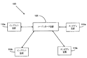
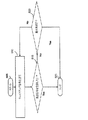
図1は、多様な実施形態が実行できる環境100のブロック構成図である。この環境は、ボディエリアネットワーク(BAN)であり得る。
FIG. 1 is a block diagram of an
環境100は、コーディネータ装置105と複数のインプラント装置(IMD)、例えばインプラント装置110a及びインプラント装置110bを含む。環境100は、また複数のオンボディ装置(OBD)、例えばオンボディ装置115a及びオンボディ装置115bを含む。コーディネータ装置105は、IMD及びOBDと電子通信を遂行する。コーディネータ装置105は、例としてコンピュータ、ラップトップコンピュータ、モバイルデバイス、携帯用デバイス、個人用携帯情報端末(PDA)、及び医療用アプリケーションに使用される電子装備を含み、これらに限定されるものではない。IMDは、生物体内に移植される電子デバイスである。OBDは、生物体上に又は生物体に近く位置するデバイスである。コーディネータ装置105は、生物体上に又は生物体に近接するように位置してチャンネルを制御し、一つ又はそれ以上のIMD及びOBDにネットワークアクセスを提供するデバイスである。
The
IMD及びOBDは、コーディネータ装置とのデータ通信のために使われる。例えば、ボディエリアネットワーク(BAN)は、コーディネータ装置105と通信する電子デバイスを含む。
The IMD and OBD are used for data communication with the coordinator device. For example, the body area network (BAN) includes electronic devices that communicate with the
コーディネータ装置105とIMD及びOBDとの間には多重通信チャンネルが存在し、データの通信は、通信チャンネルのうちいずれか一つを利用して行われる。一実施形態において、IMD110aは、スリープ(sleep)状態にあり、コーディネータ装置105は、データ通信のためにIMD110aにウェイクアップ信号を送信する。他の実施形態において、コーディネータ装置105は、データ通信のためにOBD115aから要求を受信する。
Multiple communication channels exist between the
コーディネータ装置105は、非常信号を識別するための一つ又はそれ以上の要素を含む。要素を含むコーディネータ装置105は、図2で詳細に説明される。
The
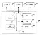
図2は、一実施形態によるコーディネータ装置105を示すブロック構成図である。コーディネータ装置105は、情報を通信するためのバス205と、情報を処理するためにバス205に結合されるプロセッサ210とを含む。また、コーディネータ装置105は、メモリ215、例えばプロセッサ210により要求される情報を格納するためにバス205に結合されるRAM(Random Access Memory)を含む。メモリ215は、プロセッサ210により要求される臨時情報を格納するために使用できる。コーディネータ装置105は、プロセッサ210により要求される静的情報を格納するためにバス205に結合されるROM(Read Only Memory)220をさらに含む。格納部225、例えば磁気ディスク、ハードディスク、又は光ディスクは、情報を格納するためにバス205に提供及び結合することができる。
FIG. 2 is a block diagram illustrating the
コーディネータ装置105は、バス205を介して情報をディスプレイするためのディスプレイ230、例えばCRT(Cathode Ray Tube)又はLCD(Liquid Crystal Display)に接続される。多様なキーを含む入力装置235は、情報をプロセッサ210に通信するためにバス205に接続される。プロセッサ210に情報を通信するために使用されるカーソル制御器240、例えばマウス、トラックボール、ジョイスティック、又はカーソル方向キーは、コーディネータ装置105に結合することができる。
The
一部の実施形態において、本発明の段階は、プロセッサ210を用いてコーディネータ装置105により遂行される。この情報は、機械読み取り可能な媒体(machine-readable medium)、例えば格納部225からメモリ215に読み取り可能である。他の実施形態において、ハードワイヤード回路(hard-wired circuitry)は、多様な実施形態を実行するためにソフトウェア命令を代替し、あるいは組み合わせて使われることができる。
In some embodiments, the steps of the present invention are performed by the
機械読み取り可能な媒体は、機械が特定機能を遂行するように機械にデータを提供する媒体として定義される。この機械読み取り可能な媒体は、格納媒体であり得る。格納媒体は、不揮発性媒体と揮発性媒体を含むことができる。この格納部225は、不揮発性媒体であり得る。メモリ215は、揮発性媒体であり得る。このようなすべての媒体は、媒体に格納されている命令を機械内に読み取る物理的メカニズムにより感知されるように実在するものでなければならない。
A machine-readable medium is defined as a medium that provides data to a machine such that the machine performs a specific function. The machine readable medium can be a storage medium. Storage media can include non-volatile media and volatile media. The
機械読み取り可能な媒体の例としては、フロッピー(登録商標)ディスク、フレキシブルディスク、ハードディスク、磁気テープ、CD-ROM、光ディスク、パンチカード、ペーパーテープ、RAM、PROM、EPROM、及びFLASH-EPROMを含み、これらに限定されない。 Examples of machine readable media include floppy (registered trademark) disks, flexible disks, hard disks, magnetic tapes, CD-ROMs, optical disks, punch cards, paper tapes, RAM, PROM, EPROM, and FLASH-EPROM, It is not limited to these.
コーディネー装置105は、信号及びデータ通信を可能にするために、バス205に接続された通信インターフェース245を含む。通信インターフェース245は、例としてジグビーポート、又はIEEE(Institute of Electrical and Electronic Engineers)802.15.6タスクグループによって規定された無線ポートを含み、これに限定されるものではない。通信インターフェース245は、IMD及びOBDと電子通信を遂行する。多重通信チャンネルが通信インターフェース245と接続することができる。
一部の実施形態において、プロセッサ210は、自身の一つ又はそれ以上の機能を遂行するための一つ又はそれ以上の処理装置を含むことができる。この処理装置は、特定機能を遂行するハードウェア回路である。
In some embodiments, the
一つ又はそれ以上の機能は、コーディネータ装置105でインプラント医療用通信サービス(medical implant communication service:MICS)送受信器によってMICSチャンネルを獲得するステップを含む。この機能は、非MICSチャンネルでインプラント装置、例えばIMD110aにウェイクアップ過程を指示する信号を送信するステップを有する。また、この方法は、MICS送受信器によってインプラント装置にピコネットとの接続を指示する命令信号を送信するステップを有する。命令信号は、装置識別子を含む。また、この機能は、命令信号をインプラント装置に送ることに基づいてコーディネータ装置105のMICS送受信器によって承認信号を受信するステップをさらに有する。承認信号は、セキュリティ制御フィールドを含む。また、この機能は、セキュリティ制御フィールドに基づいてIMD110aを認証するステップ、この認証に基づいて暗号化及び復号化のうちの一つを遂行するステップ、再生保護を実行するステップ、及びデータフレームに対するインテグリティ(integrity)保護を可能にするステップを含むセキュリティ手順を開始するステップを有する。また、この機能は、開始に基づいてコーディネータ装置105とIMD110aとの間でデータを交換するステップ及び命令メッセージを送信してIMD110aを分離(disassociating)するステップを有する。命令メッセージは、ユニキャストメッセージ、マルチキャストメッセージ、及びブロードキャストメッセージのうちいずれか一つを含む。
One or more functions include acquiring a MICS channel at the
OBDとの通信のために、プロセッサ210の機能は、コーディネータ装置105で送受信器によって通信チャンネルを獲得するステップを有する。この機能は、オンボディ装置、例えばOBD115aからコーディネータ装置情報のための要求を受信するステップを有する。また、この機能は、オンボディ装置からピコネットとの接続のための接続要求を受信するステップを有する。また、接続要求は、一つ又はそれ以上のパラメータを含む。また、この機能はコーディネータ装置105に対して定義された複数の許可制御パラメータに基づいて接続要求を決定するステップを有する。この機能は、決定に基づいてメッセージ信号で接続要求を承認するステップを有する。メッセージ信号は、ピコネットでOBD115aに対する装置識別子を含む受諾メッセージ信号と接続要求を拒絶する理由を含む拒絶メッセージ信号のうちいずれか一つを含む。上記機能は、セキュリティ制御フィールドに基づいてOBD115aを認証するステップ、認証に基づいて暗号化及び復号化のうちの一つを遂行するステップ、及びデータフレームに対するインテグリティ保護を可能にするステップのうちいずれか一つを含むセキュリティ手順を開始するステップを有する。また、この機能は、開始に基づいてコーディネータ装置105とOBD115aとの間でデータを交換するステップを有する。また、この機能は、命令メッセージを送信してOBD115aを分離するステップを有する。命令メッセージは、ユニキャストメッセージ、マルチキャストメッセージ、及びブロードキャストメッセージのうちいずれか一つを含む。
For communication with the OBD, the function of the
各IMD、例えば、IMD110a、及び各OBD、例えば、OBD115aは、構造的にコーディネータ装置105に類似することができ、コーディネータ装置115のために示すような多様な要素を備えることに注意すべきである。図2のコーディネータ装置105の各要素の機能性は、プロセッサ210を除いてはIMD110a及びOBD115aと同様であり得る。
It should be noted that each IMD, eg,
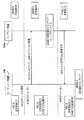
図3乃至図4は、コーディネータ装置、例えばコーディネータ装置105を用いてボディエリアネットワーク内の複数のインプラント装置(IMD)を管理するための方法を示すフローチャートである。
3-4 are flowcharts illustrating a method for managing a plurality of implant devices (IMDs) in a body area network using a coordinator device, eg, the
一実施形態において、IMD、例えばIMD110aは、ディープスリープモードである。ディープスリープモードは、IMDが電源は供給されるが非動作状態にあるとして定義され得る。ディープスリープモードでは、非MICS受信器のエネルギー検出器がデューティサイクリングモードで活性化される。IMDは、非常状態で又はウェイクアップ過程がコーディネータ装置によって開始されるときに動作する。
In one embodiment, the IMD, eg,
上記方法は、ステップ305で開始する。 The method begins at step 305.
ステップ310で、MICSチャンネルは、コーディネータ装置でMICS送受信器によって獲得される。MICSチャンネルは、最初に所定の期間でMICSチャンネルを感知する。MICSチャンネルが、如何なる干渉もないと決定されると、MICSチャンネルが通信のためにコーディネータ装置によって獲得される。 In step 310, the MICS channel is acquired by the MICS transceiver at the coordinator device. The MICS channel first senses the MICS channel for a predetermined period. If the MICS channel is determined to be free of any interference, the MICS channel is acquired by the coordinator device for communication.
また、MICSチャンネルを獲得した後に、獲得されたMICSチャンネル上の非活性期間が予め定義された期間と同一であり、あるいは超えると、コーディネータ装置は、パケット、例えばヌルパケット(null packet)を送信してMICSチャンネルを維持できる。 In addition, after acquiring the MICS channel, if the inactivity period on the acquired MICS channel is the same as or exceeds the predefined period, the coordinator device transmits a packet, for example, a null packet. Can maintain the MICS channel.
ステップ315で、ウェイクアップ過程を指示する信号が非MICSチャンネルでIMDに送信される。この信号は、IMDでウェイクアップ過程を開始するためにコーディネータ装置によって送信されることができる。この信号は、非MICS送信器、例えば2.4GHzを用いてコーディネータ装置によって送信される。この信号は、MICSチャンネルと関連した情報を含む。 In step 315, a signal indicating the wake-up process is transmitted to the IMD over the non-MICS channel. This signal can be sent by the coordinator device to initiate the wake-up process at the IMD. This signal is transmitted by the coordinator device using a non-MICS transmitter, for example 2.4 GHz. This signal contains information associated with the MICS channel.
一実施形態において、非MICS帯域は、同一に位置した同一の帯域幅のN個のチャンネルに分割される。IMDとコーディネータ装置両方は、干渉が大きいチャンネルを避ける。しかしながら、干渉レベルは、IMDとコーディネータ装置の両方に対して相互に異なることができる。例えば、コーディネータ装置に対して管理可能な干渉レベルがIMDからより低く設定することができる。 In one embodiment, the non-MICS band is divided into N channels of the same bandwidth that are located the same. Both IMD and coordinator devices avoid channels with high interference. However, the interference levels can be different from each other for both the IMD and the coordinator device. For example, the interference level manageable for the coordinator device can be set lower than the IMD.
非MICS帯域のチャンネルで干渉が検出されないと、コーディネータ装置は、信号を搬送波感知多重アクセス及び衝突回避技術を用いてウェイクアップ過程の開始を指示するIMDに上記信号を送信する。この信号は、管理可能な干渉レベル内で非MICSチャンネルで送信される。一部の実施形態において、上記信号が信頼性を増大させるために管理可能な干渉レベル内で各非MICSチャンネルでまた送られることができる。一部の実施形態では、承認がコーディネータ装置によって受信されるまでランダムな順序で管理可能な干渉レベル内で非MICSチャンネルで送信される。 If no interference is detected on the non-MICS band channel, the coordinator device transmits the signal to the IMD instructing the start of the wake-up process using carrier sense multiple access and collision avoidance techniques. This signal is transmitted on a non-MICS channel within manageable interference levels. In some embodiments, the signal can also be sent on each non-MICS channel within manageable interference levels to increase reliability. In some embodiments, acknowledgments are transmitted on non-MICS channels within manageable interference levels in a random order until received by the coordinator device.
ディープスリープモードで、より少ない干渉を有する非MICSチャンネルでIMDデューティは、エネルギー検出器上でサイクリングされる。この信号を受信すると、IMDは、承認信号を送ることができる。 In deep sleep mode, the IMD duty is cycled on the energy detector in a non-MICS channel with less interference. Upon receiving this signal, the IMD can send an acknowledgment signal.
一部の実施形態において、承認信号は、IMDへの上記信号の送信に基づいてコーディネータ装置のMICS送受信器によって受信される。 In some embodiments, the acknowledgment signal is received by the MICS transceiver of the coordinator device based on the transmission of the signal to the IMD.
一部の実施形態において、定義された期間内にインプラント装置から承認信号が受信されるまで、上記信号は、非MICSチャンネル上に再送信される。一部の実施形態で、信号が定義された期間内に、承認信号がMICSチャンネルで受信されないと、この信号は、他の非MICSチャンネル上に再送信される。 In some embodiments, the signal is retransmitted on a non-MICS channel until an acknowledgment signal is received from the implant device within a defined period of time. In some embodiments, if an acknowledgment signal is not received on the MICS channel within a defined period of time, the signal is retransmitted on other non-MICS channels.
ステップ320で、ピコネットとの結合を指示する命令信号がMICS送受信器によってインプラント装置に送信される。命令信号は、コーディネータ装置によって指定されたIMD用の装置識別子を含む。 At step 320, a command signal indicating coupling with the piconet is transmitted to the implant device by the MICS transceiver. The command signal includes a device identifier for the IMD specified by the coordinator device.
一実施形態で、命令信号は、インプラント装置への信号送信に応答して送信される承認信号を受信した後に送信される。 In one embodiment, the command signal is transmitted after receiving an approval signal that is transmitted in response to transmitting the signal to the implant device.
ステップ325で、承認信号は、インプラント装置に送られた命令信号に基づいてコーディネータ装置のMICS送受信器によって受信される。承認信号は、IMDでセキュリティ要件を定義するセキュリティ制御フィールドを含む。 At step 325, the approval signal is received by the MICS transceiver of the coordinator device based on the command signal sent to the implant device. The approval signal includes a security control field that defines security requirements in the IMD.
一部の実施形態において、IMDは、セキュリティ制御フィールドを有する承認信号が送信される前にこの信号と命令信号が受信されるまで待機する。 In some embodiments, the IMD waits until this signal and a command signal are received before an acknowledgment signal having a security control field is transmitted.
ステップ330で、セキュリティ手順は、セキュリティ制御フィールドに基づいて開始される。
At
セキュリティレベルは、一つのバイトビットマップを用いてセキュリティ制御フィールドに表示される。各ビットは、次のようにセキュリティ特性のサポートを指示するために使用される。
ビット0−認証
ビット1−インテグリティ保護
ビット2−暗号化及び復号化
ビット3−フレームカウンタを用いる再生保護
ビット4−一つのセッションですべてのフレームに対する同一のセキュリティ
ビット5−キーサイズ192ビット
ビット6−キーサイズ256ビット
ビット7−将来の使用のために予備(RFU)
The security level is displayed in the security control field using one byte bitmap. Each bit is used to indicate security property support as follows.
セキュリティが必要でない場合、セキュリティ制御フィールドのビットは、0に設定される。使用されるデフォルトキーサイズは、128ビットキーとして設定される。セキュリティの異なるレベルは、一つのバイトビットマップを用いて多様なデバイスに対して実行することができる。IMDにより指示されるセキュリティレベルが許容されないと、コーディネータ装置は、接続に失敗する可能性がある。セキュリティ制御フィールドは、セキュリティ制御、アプリケーションによって相互に異なるセキュリティ特性が各フレームに対して選択される接続手順の間に交換されるアプリケーションパラメータフィールド、及びBAN装置要件を用いてMACフレームにフレームレベルセキュリティを定義する。一部の実施形態において、フレームレベルセキュリティは、類似したフレームレベルセキュリティがセキュリティ保護を必要とするフレームに対して均一に使用される接続手順の間に識別される。 If security is not required, the security control field bit is set to zero. The default key size used is set as a 128-bit key. Different levels of security can be implemented for a variety of devices using a single byte bitmap. If the security level indicated by the IMD is not allowed, the coordinator device may fail to connect. The security control field provides frame-level security for MAC frames using security controls, application parameter fields that are exchanged during each connection procedure in which different security characteristics are selected for each frame, and BAN device requirements. Define. In some embodiments, frame level security is identified during a connection procedure where similar frame level security is used uniformly for frames that require security protection.
一部の機能(capabilities)は、セキュリティレベルの実行のためにコーディネータ装置とIMDで遂行される。 Some capabilities are performed by the coordinator device and the IMD for security level execution.
コーディネータ装置は、次のような詳細を有するように事前構成することができる。
IMDがサポートするとコーディネータ装置が期待する最小セキュリティモード。
The coordinator device can be preconfigured to have the following details.
The minimum security mode that the coordinator device expects the IMD to support.
セキュリティテーブルは、次のフィールドを含むコーディネータ装置の不揮発性メモリに格納される。
各クライアントデバイス用共有キー(マスターキーID(MKID)と呼ばれる識別子によって識別される複数のキー)。この場合にクライアントデバイスは、IMDであり得る。
デバイスID、MACアドレス、デバイスのタイプ、クライアントにより提供されるサービス。このような情報は、接続手順によって予め格納され、あるいは収集できることである。この情報は、クライアントデバイスがコーディネータ装置から分離された後にクライアントデバイス内に保持される。
The security table is stored in the non-volatile memory of the coordinator device including the following fields.
A shared key for each client device (a plurality of keys identified by an identifier called a master key ID (MKID)). In this case, the client device may be an IMD.
Device ID, MAC address, device type, service provided by the client. Such information is stored in advance or can be collected according to the connection procedure. This information is retained in the client device after the client device is disconnected from the coordinator device.
また、BAN装置は、コーディネータ装置のようにセキュリティキーと該当MKIDで事前構成することができる。デバイスID、MACアドレス、デバイスのタイプ、クライアントデバイスによって提供されるサービスがクライアントデバイスで事前構成することができる。 In addition, the BAN device can be preconfigured with a security key and a corresponding MKID like a coordinator device. The device ID, MAC address, device type, and services provided by the client device can be preconfigured at the client device.
IMDとコーディネータ装置は、キーが以後セッションで再交渉されるまで臨時キーとフレームカウンタを格納する機能を有する。 The IMD and coordinator device have the function of storing a temporary key and a frame counter until the key is renegotiated in the session thereafter.
ステップ335で、IMDは、マスターキーがコーディネータ装置とIMDとの間で共有されることを認める4方式のハンドシェイク(handshake)手順を用いて認証される。
At
ステップ340で、暗号化と復号化を可能にするペアワイズキー生成が認証に基づいて遂行される。例えば、AES-128カウンタモードがデータ暗号化のために使われることができる。
In
ステップ345で、再生保護が実行される。
At
フレームカウンタは再生保護のために使用される。2バイトフレームカウンタが使われることができる。以前セッションからのフレームカウンタの値はコーディネータ装置とIMDに格納する必要がある。以後セッションは、以前セッションから格納されたフレームカウンタから続けてカウンティングし、あるいは新たなランダムフレームカウンタで再び開始することを選択できる。 The frame counter is used for playback protection. A 2-byte frame counter can be used. The value of the frame counter from the previous session needs to be stored in the coordinator device and the IMD. Thereafter, the session can choose to continue counting from the frame counter stored from the previous session or to start again with a new random frame counter.
ステップ350で、データフレームに対するインテグリティ保護が可能である。
In
AES-128暗号ブロック連鎖メッセージ認証コード(Cipher Block Chaining-Message Authentication Code:CBC-MAC)は、インテグリティチェック計算のために使用できる。インテグリティチェックは、データフレームに含まれることができる。 An AES-128 Cipher Block Chaining Message Authentication Code (CBC-MAC) can be used for the integrity check calculation. An integrity check can be included in the data frame.
MACプロトコルは、IMDとコーディネータ装置から送信されたデータフレームに使用されるプライバシーとインテグリティ保護を選択的に使用することができる。セキュリティヘッダーフィールドは、このような選択を指示するために使われる。コーディネータ装置から送られた標準フレーム、例えばポール(poll)又は他の制御フレームは、暗号化され、あるいはインテグリティ保護される必要がない。 The MAC protocol can selectively use privacy and integrity protection used for data frames transmitted from the IMD and coordinator devices. The security header field is used to indicate such a selection. Standard frames sent from the coordinator device, such as polls or other control frames, need not be encrypted or integrity protected.
ステップ355で、データは、ステップ330での開始に基づいてコーディネータ装置とIMDとの間で交換される。データ交換は、ステップ330で定義されたセキュリティ手順に基づいて遂行できる。
At
コーディネータ装置が複数のIMDと通信する場合に、データは、コーディネータ装置によってブロードキャスティングされ、あるいは各IMDに個別的に送信することができる。データを受信すると、各IMDは、コーディネータ装置に応答を送る。このようなデータの例としては、命令信号、データフレーム、ポールメッセージ、データ要求、制御信号、及び動作信号を含み、これらに限定されるものではない。例えば、IMDがコーディネータ装置からデータフレームを受信する場合、IMDは、データ承認信号をコーディネータ装置に送信する。一部の実施形態において、コーディネータ装置からデータを受信すると、応答がIMDにより送信されない。 When the coordinator device communicates with multiple IMDs, the data can be broadcast by the coordinator device or sent individually to each IMD. Upon receiving data, each IMD sends a response to the coordinator device. Examples of such data include, but are not limited to, command signals, data frames, poll messages, data requests, control signals, and operation signals. For example, if the IMD receives a data frame from the coordinator device, the IMD sends a data acknowledgment signal to the coordinator device. In some embodiments, upon receiving data from the coordinator device, no response is sent by the IMD.
ステップ360で、インプラント装置は、命令メッセージを送信して分離される。命令メッセージは、ユニキャストメッセージ、マルチキャストメッセージ、及びブロードキャストメッセージのうちいずれか一つを含む。分離は、IMDに命令メッセージを送信して装置識別子を解除して遂行できる。 At step 360, the implant device is disconnected by sending a command message. The command message includes any one of a unicast message, a multicast message, and a broadcast message. Separation can be performed by sending a command message to the IMD to release the device identifier.
一実施形態において、コーディネータ装置は、エンドセッションメッセージをIMDにブロードキャスティング又はマルチキャスティングして複数のIMDを分離できる。 In one embodiment, the coordinator device can broadcast or multicast an end session message to an IMD to separate multiple IMDs.
一部の実施形態では、IMDは、コーディネータ装置から分離できる。 In some embodiments, the IMD can be separated from the coordinator device.
上記方法は、ステップ365で終了する。
The method ends at
一部の実施形態において、コーディネータ装置は、非常イベントを有するIMDから非常信号を受信するための他のMICS送受信器又はMICS受信器を含むことができる。他のMICS送受信器又はMICS受信器は、非常信号を聞くためにより少ない干渉を有するMICSチャンネルでデューティサイクリングできる。受信された複数の信号が非ボディエリアネットワーク信号であると、非MICSチャンネルの受信器周波数は、受信器周波数に比べてより少ない干渉を有する他の周波数にシフトされる。非常信号は。受信された非常信号でペイロードヘッダーを用いて識別できる。 In some embodiments, the coordinator device may include other MICS transceivers or MICS receivers for receiving emergency signals from IMDs having emergency events. Other MICS transceivers or MICS receivers can be duty cycled on MICS channels that have less interference to hear emergency signals. If the received signals are non-body area network signals, the receiver frequency of the non-MICS channel is shifted to another frequency that has less interference compared to the receiver frequency. Emergency signal. The received emergency signal can be identified using the payload header.
一実施形態において、他のMICS送受信器で非常信号を受信すると、コーディネータ装置はIMDと進行中である通信を中断させ、MICS送受信器は非常状況に対処するために他のインプラント装置と通信を始める。 In one embodiment, upon receiving an emergency signal at another MICS transceiver, the coordinator device interrupts the ongoing communication with the IMD, and the MICS transceiver initiates communication with the other implant device to cope with the emergency situation. .
他の実施形態において、他のMICS送受信器で非常信号を受信すると、コーディネータ装置は、正常な通信を中断することなく非常事態を処理する。 In other embodiments, upon receiving an emergency signal at another MICS transceiver, the coordinator device handles the emergency without interrupting normal communication.
一実施形態において、コーディネータ装置は、第1のIMDと通信する。このコーディネータ装置は、第2のIMDに接続するように要求される。この場合、コーディネータ装置は、第1のIMDに保持命令を受信すると、第1のIMDは、スリープモードに進み、あるいはスイッチオフされる。第1のIMDは、所定の時間以後に、又は所定の期間にわたって周期的に動作するように開始される。その後、コーディネータ装置は、図3及び図4に示された方法に基づいて第2のIMDとの接続を開始する。第2のIMDとの接続を達成すると、コーディネータ装置は、第1のIMDに非保持(unhold)命令を送信する。一実施形態において、第1のIMDは、所定時間の完了後に動作される。 In one embodiment, the coordinator device communicates with the first IMD. This coordinator device is required to connect to the second IMD. In this case, when the coordinator device receives a hold command on the first IMD, the first IMD proceeds to sleep mode or is switched off. The first IMD is started to operate after a predetermined time or periodically over a predetermined period. Thereafter, the coordinator device starts connection with the second IMD based on the method shown in FIGS. 3 and 4. Upon achieving a connection with the second IMD, the coordinator device sends an unhold command to the first IMD. In one embodiment, the first IMD is operated after completion of the predetermined time.
第2の実施形態において、コーディネータ装置は、MICSチャンネルで第1のIMDと通信する。コーディネータ装置は、第2のIMDに接続するように要求される。コーディネータ装置は、非MICSチャンネルで第2のIMDにウェイクアップ信号を送信する。ウェイクアップ信号を受信すると、第2のIMDは、搬送波感知多重アクセス及び衝突回避技術を用いてMICSチャンネルで承認信号を送信する。コーディネータ装置が承認信号を受信する場合に、コーディネータ装置は、図3及び図4で説明した方法に基づいて第2のIMDとの接続を開始する。 In the second embodiment, the coordinator device communicates with the first IMD over the MICS channel. The coordinator device is required to connect to the second IMD. The coordinator device transmits a wake-up signal to the second IMD over the non-MICS channel. Upon receiving the wake-up signal, the second IMD transmits an acknowledgment signal on the MICS channel using carrier sense multiple access and collision avoidance techniques. When the coordinator device receives the approval signal, the coordinator device starts connection with the second IMD based on the method described in FIGS. 3 and 4.
図5は、一実施形態によるボディエリアネットワークにおけるコーディネータ装置によってチャンネルを獲得する方法を示すフローチャートである。 FIG. 5 is a flowchart illustrating a method for acquiring a channel by a coordinator apparatus in a body area network according to an embodiment.
上記方法は、ステップ405で開始する。 The method starts at step 405.
ステップ410で、複数のチャンネルでエネルギー検出スキャンが遂行される。各チャンネルは、エネルギーを検出するために所定の期間で感知される。 In step 410, an energy detection scan is performed on the plurality of channels. Each channel is sensed for a predetermined period of time to detect energy.
ステップ415で、フリーチャンネルのリストが決定される。フリーチャンネルリストは、低い干渉でチャンネルを識別して決定することができる。 At step 415, a list of free channels is determined. The free channel list can be determined by identifying channels with low interference.
一実施形態において、フリーチャンネルが決定されないと、チャンネル獲得のための上記方法は終了する。 In one embodiment, if a free channel is not determined, the method for channel acquisition ends.
ステップ420で、少なくとも干渉を有するチャンネルがフリーチャンネルリストから選択される。 In step 420, a channel having at least interference is selected from the free channel list.
ステップ425で、チャンネル獲得メッセージは、チャンネルがBANの他のコーディネータ装置によって活用されるか否かを決定するためにブロードキャスティングされる。 In step 425, the channel acquisition message is broadcast to determine whether the channel is utilized by other coordinator devices in the BAN.
ステップ430で、ブロードキャスティングされたメッセージに対して応答が受信されたか否かが決定される。応答が受信されない場合には、ステップ435が遂行される。 At step 430, it is determined whether a response has been received for the broadcasted message. If no response is received, step 435 is performed.
選択されたチャンネルが他のコーディネータ装置によって活用されていることを示す応答が受信されると、ステップ415が遂行される。 If a response is received indicating that the selected channel is being utilized by another coordinator device, step 415 is performed.
上記方法は、ステップ435で終了する。 The method ends at step 435.
図6は、一実施形態によるウェイクアップ過程のフローを示す。 FIG. 6 shows a flow of a wake-up process according to an embodiment.
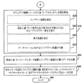
このフロー図は、コーディネータ装置、例えばコーディネータ装置105及び現在ディープスリープモードであるIMD、例えばIMD110a間の通信のためのMICSチャンネルでポーリング(polling)が使用されない場合のウェイクアップ過程を示す。
The flow diagram illustrates a wake-up process when polling is not used in a MICS channel for communication between a coordinator device, eg,
最初に、MICS送受信器は、MICSチャンネル獲得を遂行するためにコーディネータ装置105によってスイッチオンされる。また、IMD110aで、非MICS受信器は、ウェイクアップ信号を聞くためにスイッチオンされる。
Initially, the MICS transceiver is switched on by the
MICSチャンネルを獲得すると、非MICS送信器がコーディネータ装置105によりスイッチオンされ、MICSチャンネル情報を含むウェイクアップ信号はIMDに送信される。IMD110aでの非MICS受信器は、ウェイクアップ信号を受信し、IMDに指示する。IMD110aは、ウェイクアップ過程が完了したことを指示するコーディネータ装置105に承認信号を送信するためにIMDのMICS送受信器をスイッチオンする。コーディネータ装置は、承認信号を受信すると、非MICS送信器をスイッチオフする。
Upon acquisition of the MICS channel, the non-MICS transmitter is switched on by the
図7は、一実施形態によるコーディネータ装置、例えばコーディネータ装置105でのウェイクアップ過程を示すフローチャートである。
FIG. 7 is a flowchart illustrating a wake-up process in a coordinator device according to an embodiment, for example, the
上記方法は、ステップ605で開始する。
The method starts at
ステップ610で、ウェイクアップ信号は、コーディネータ装置によってIMDに送信される。コーディネータ装置は、承認信号を受信するために所定時間を待機する。
At
ステップ615で、承認信号が受信されたか否かを決定する。
In
承認信号が受信されない場合には、ステップ620が遂行され、そうでない場合には、ステップ625が遂行される。
If no acknowledgment signal is received,
ステップ620で、ウェイクアップ信号を送信する最大再試行が遂行されるか否かが決定される。
At
最大再試行が遂行される場合には、ステップ625が遂行され、そうでないと、ステップ610が遂行される。
If maximum retry is performed,
一実施形態において、最大再試行が遂行されると、図7の方法は他のMICSチャンネルを用いて遂行される。 In one embodiment, when maximum retry is performed, the method of FIG. 7 is performed using another MICS channel.
上記方法は、ステップ625で終了する。
The method ends at
図8は、一実施形態によるコーディネータ装置、例えばコーディネータ装置105での他のウェイクアップ過程を示すフローチャートである。
FIG. 8 is a flowchart illustrating another wake-up process in the coordinator device, for example, the
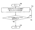
上記方法は、ステップ705で開始する。
The method starts at
ステップ710で、ウェイクアップ信号は、所定の期間でコーディネータ装置によってIMDに送信される。所定の期間中に、ウェイクアップ信号は、非MICSチャンネルでIMDに連続してN回送信される。
In
ステップ715で、ウェイクアップ信号は、すべての非MICSチャンネルで送信されるか否かが決定される。 At step 715, it is determined whether a wake-up signal is transmitted on all non-MICS channels.
すべての非MICSチャンネルが活用されると、ステップ720が遂行され、そうでない場合には、ステップ710が他のMICSチャンネルに対して遂行される。
If all non-MICS channels are utilized,
上記方法は、ステップ720で終了する。
The method ends at
図9は、他の実施形態によるウェイクアップ過程のフローを示す。 FIG. 9 shows a flow of a wake-up process according to another embodiment.
フロー図は、コーディネータ装置105とディープスリープモードであるIMD110aとの間の通信のためにポーリングが使用される場合のウェイクアップ過程を示す。
The flow diagram illustrates a wake-up process when polling is used for communication between the
最初に、MICS送受信器は、MICSチャンネルの獲得を遂行するためにコーディネータ装置105によってスイッチオンされる。また、IMD110aで、非MICS受信器は、ウェイクアップ信号を聞くためにスイッチオンされる。
Initially, the MICS transceiver is switched on by the
MICSチャンネルを獲得すると、非MICS送信器は、コーディネータ装置105によりスイッチオンされ、ウェイクアップ信号はIMDに送信される。IMD110aでの非MICS受信器は、ウェイクアップ信号を受信し、IMDに指示する。IMD110aは、非MICS受信器をスイッチオフし、ピコネットとの結合を指示する命令信号を待機する。命令信号を受信すると、IMD110aは、承認信号をコーディネータ装置105に送信ためにIMDのMICS送受信器をスイッチオンする。コーディネータ装置105は、承認信号を受信すると、非MICS送信器をスイッチオフし、ウェイクアップ過程は終了する。
Upon acquiring the MICS channel, the non-MICS transmitter is switched on by the
図10は、他の実施形態によるコーディネータ装置、例えばコーディネータ装置105でのウェイクアップ過程を示すフローチャートである。
FIG. 10 is a flowchart illustrating a wake-up process in a coordinator device according to another embodiment, for example, the
上記方法は、ステップ905で始まる。
The method begins at
ステップ910で、ウェイクアップ信号は、コーディネータ装置によってIMDに送信される。
In
ステップ915で、ピコネット結合を指示する命令信号は、ウェイクアップ信号を送信する所定の期間以後にIMDに送られる。コーディネータ装置は、承認信号を受信するために他の期間の間に待機する。
In
ステップ920で、承認信号が受信されたか否かが決定される。
At
承認信号が受信されない場合、ステップ925が遂行され、そうでない場合には、ステップ930が遂行される。
If an acknowledgment signal is not received,
ステップ925で、ウェイクアップ信号を送信する最大再試行が遂行されるか否かが決定される。
At
最大再試行が遂行されると、ステップ930が遂行され、そうでないと、ステップ910が遂行される。
If maximum retry is performed,
上記方法は、ステップ930で終了する。
The method ends at
図11乃至図12は、コーディネータ装置、例えばコーディネータ装置105を用いてボディエリアネットワークで複数のオンボディ装置を管理する方法を示すフローチャートである。
11 to 12 are flowcharts illustrating a method for managing a plurality of on-body devices in a body area network using a coordinator device, for example, the
オンボディ装置、例えばオンボディ装置(OBD)115aは、オンボディ装置を扱う機能を有するコーディネータ装置の発見を遂行する。 An on-body device, such as an on-body device (OBD) 115a, performs the discovery of a coordinator device having the function of handling the on-body device.
一実施形態において、コーディネータ装置は、ボディエリアネットワークで機能をブロードキャスティングできる。他の実施形態においては、オンボディ装置は、情報要求をコーディネータ装置に送ることができる。 In one embodiment, the coordinator device can broadcast functions in a body area network. In other embodiments, the on-body device can send a request for information to the coordinator device.
上記方法は、ステップ1005で開始する。
The method starts at
ステップ1010で、通信チャンネルの周波数は、コーディネータ装置の送受信器により獲得される。
In
周波数は、所定の期間で通信チャンネルの周波数を初期に感知することによって得られる。通信チャンネルでの周波数がいかなる干渉もないと決定される場合、コーディネータ装置は、通信チャンネルを獲得するためにチャンネル通知(announcement)を遂行する。チャンネル通知に対して応答が受信されない場合には、通信チャンネルが獲得される。 The frequency is obtained by initially sensing the frequency of the communication channel over a predetermined period. If the frequency on the communication channel is determined to be free of any interference, the coordinator device performs a channel announcement to acquire the communication channel. If no response is received for the channel notification, a communication channel is acquired.
ステップ1015で、コーディネータ装置情報に対する要求は、OBDから受信される。この要求は、コーディネータ装置の機能とコーディネータ装置用識別子を含む。
At
コーディネータ装置は、その機能と識別子を送信できる。 The coordinator device can transmit its function and identifier.
一実施形態において、コーディネータ装置情報は、コーディネータ装置によってブロードキャスティングできる。 In one embodiment, the coordinator device information can be broadcast by the coordinator device.
ステップ1020で、ピコネットとの結合のための接続要求がOBDから受信される。接続要求は、一つ又はそれ以上のパラメータ、例えばオンボディ装置情報、平均データレート、パケットサイズ、内部パケット到着時間、MAC層で送信したパケットのサイズ、遅延要件、及びセキュリティ制御フィールドを含む。
At
ステップ1025で、接続要求は、コーディネータ装置に対して定義された複数の許可制御パラメータに基づいて決定される。許可制御パラメータの例としては、保証されたタイムスロットの可用性(availability)を含み、これに限定されるものではない。
At
ステップ1030で、接続要求は、決定に基づいてメッセージ信号で承認される。このメッセージは、ピコネットでOBDに対する装置識別子を含む受諾メッセージ信号、及び接続要求を拒絶する理由を含む拒絶メッセージ信号のうちいずれか一つであり得る。
At
ステップ1035で、セキュリティ手順は、セキュリティ制御フィールドに基づいて開始できる。
At
セキュリティ制御フィールド内のセキュリティレベルは、一つのバイトビットマップを用いて表示される。各ビットは、次のようにセキュリティ特性サポートを表すために使われる。
ビット0−認証
ビット1−インテグリティ保護
ビット2−暗号化及び復号化
ビット3−フレームカウンタを用いる再生保護
ビット4−一つのセッションですべてのフレームに対する同一のセキュリティ
ビット5−キーサイズ192ビット
ビット6−キーサイズ256ビット
ビット7−RFU
The security level in the security control field is displayed using one byte bitmap. Each bit is used to represent security property support as follows:
セキュリティが必要でない場合、セキュリティ制御フィールド内のビットは0に設定される。デフォルトキーサイズは128ビットキーに設定できる。異なるレベルのセキュリティは、一つのバイトビットマップを用いて多様なデバイスに対して遂行できる。オンボディ装置によって指示されるセキュリティレベルが許容できないと、コーディネータ装置は、接続に失敗する。 If security is not required, the bit in the security control field is set to zero. The default key size can be set to a 128-bit key. Different levels of security can be achieved for a variety of devices using a single byte bitmap. If the security level indicated by the on-body device is not acceptable, the coordinator device will fail to connect.
一部の機能は、セキュリティレベルの実行のためのコーディネータ装置とオンボディ装置で遂行される。 Some functions are performed by coordinator devices and on-body devices for security level enforcement.
コーディネータ装置は、次のような詳細を有するように予め構成される。
コーディネータ装置はオンボディ装置がサポートすると期待する最小セキュリティモード。
The coordinator device is preconfigured to have the following details.
The coordinator device is the minimum security mode that an on-body device expects to support.
セキュリティテーブルは、次のフィールドを含むコーディネータ装置の不揮発性メモリに格納される。
各クライアントデバイス用の共有キー(マスターキーID(MKID)と呼ばれる識別子により識別される複数のキー)。この場合にクライアントデバイスは、OBDであり得る。
デバイスID、MACアドレス、デバイスのタイプ、クライアントにより提供されるサービス。このような情報は、接続手順によって予め格納され、あるいは収集できることである。この情報は、クライアントデバイスがコーディネータ装置から分離された後にクライアントデバイス内に保持される。
The security table is stored in the non-volatile memory of the coordinator device including the following fields.
A shared key for each client device (a plurality of keys identified by an identifier called a master key ID (MKID)). In this case, the client device may be an OBD.
Device ID, MAC address, device type, service provided by the client. Such information is stored in advance or can be collected according to the connection procedure. This information is retained in the client device after the client device is disconnected from the coordinator device.
また、オンボディ装置は、コーディネータ装置のようにセキュリティキーと該当MKIDで事前構成することができる。デバイスID、MACアドレス、デバイスのタイプ、クライアントデバイスによって提供されるサービスがクライアントデバイスで事前構成することができる。 Further, the on-body device can be pre-configured with a security key and a corresponding MKID like a coordinator device. The device ID, MAC address, device type, and services provided by the client device can be preconfigured at the client device.
オンボディ装置とコーディネータ装置は、キーが以後セッションで再交渉されるまで臨時キーとフレームカウンタを格納する機能を有する。 The on-body device and the coordinator device have a function of storing the temporary key and the frame counter until the key is renegotiated in the session thereafter.
フレームカウンタは、再生保護のために使われる。2バイトフレームカウンタが使用できる。以前セッションからのフレームカウンタの値は、コーディネータ装置とオンボディ装置に格納する必要がある。以後セッションは、以前セッションから格納されたフレームカウンタから続けてカウンティングし、あるいは新たなランダムフレームカウンタで再開始することを選択できる。 The frame counter is used for playback protection. A 2-byte frame counter can be used. The value of the frame counter from the previous session needs to be stored in the coordinator device and on-body device. Thereafter, the session can choose to continue counting from the frame counter stored from the previous session, or restart with a new random frame counter.
ステップ1040で、OBDは、マスターキーがコーディネータ装置とOBDとの間で共有されることを認める4方式のハンドシェイク手順を用いて認証される。
At
ステップ1045で、暗号化と復号化を可能にするペアワイズキー生成は、認証に基づいて遂行される。AES-128カウンタモードは、データ暗号化のために使用することができる。
In
ステップ1050で、再生保護が実行される。
At
ステップ1055で、データフレームに対するインテグリティ保護が可能である。
In
AES-128暗号ブロック連鎖メッセージ認証コード(CBC_MAC)は、インテグリティチェック計算のために使われることができる。インテグリティチェックは、データフレームに含まれることができる。 The AES-128 cipher block chain message authentication code (CBC_MAC) can be used for the integrity check calculation. An integrity check can be included in the data frame.
MACプロトコルは、OBDとコーディネータ装置から送信されたデータフレームに使用されるプライバシーとインテグリティ保護を選択的に使用することができる。セキュリティヘッダーフィールドは、このような選択を指示するために使われる。コーディネータ装置から送信される標準フレーム、例えばポール又は他の制御フレームは、暗号化にされ、あるいはインテグリティ保護される必要がない。 The MAC protocol can selectively use privacy and integrity protection used for data frames transmitted from OBD and coordinator devices. The security header field is used to indicate such a selection. Standard frames transmitted from the coordinator device, such as polls or other control frames, need not be encrypted or integrity protected.
ステップ1060で、データは、開始に基づいてコーディネータ装置とオンボディ装置との間で交換される。
At
ステップ1065で、オンボディ装置に指定された装置識別子は、コーディネータ装置によって分離される。分離は、分離命令信号をOBDに送信して装置識別子を解除して遂行できる。
In
上記方法は、ステップ1070で終了する。
The method ends at
図13は、一実施形態によるオンボディ装置、例えばオンボディ装置115aによってコーディネータ装置を発見する方法を示すフローチャートである。
FIG. 13 is a flowchart illustrating a method of discovering a coordinator device by an on-body device, eg, on-
上記方法は、ステップ1105で開始する。
The method starts at
ステップ1110で、コーディネータ装置からブロードキャストメッセージに対する受動スキャニングが遂行される。
In
ボディエリアネットワーク内のコーディネータ装置のリストは、通信チャンネルでコーディネータ装置からのブロードキャスティングされたメッセージに基づいて生成される。ブロードキャストメッセージは、コーディネータ装置の機能と識別子を含むことができる。 A list of coordinator devices in the body area network is generated based on the broadcasted message from the coordinator device on the communication channel. The broadcast message may include the function and identifier of the coordinator device.
ステップ1115で、オンボディ装置の機能と識別子のマッチングが決定される。
At
機能と識別子のマッチングが成功的であると、ステップ1130が遂行され、そうでない場合には、ステップ1120が遂行される。
If the function and identifier matching is successful,
ステップ1120では、通信チャンネルのすべての周波数が受動スキャニングを遂行するために活用されるか否かが決定される。
In
すべての周波数が活用される場合、ステップ1135が遂行され、そうでない場合には、ステップ1125が遂行される。
If all frequencies are utilized,
ステップ1125で、通信チャンネルの周波数は、他の周波数にシフトされる。
In
ステップ1130で、ステップ1115又はステップ1125で決定された機能及び識別子マッチングに基づいて、接続手順がコーディネータ装置で始まる。
At
上記方法は、ステップ1135で終了する。
The method ends at
図14は、一実施形態によるコーディネータ装置と複数のオンボディ装置との間での認証及びセキュリティキー生成方法のフローを示す。 FIG. 14 shows a flow of an authentication and security key generation method between a coordinator device and a plurality of on-body devices according to an embodiment.
コーディネータ装置は、複数のオンボディ装置を示す代表デバイスから接続要求を受信する。複数のデバイスは、アプリケーションに基づいてグループ化でき、代表デバイスによって表示される。コーディネータ装置は、以後認証のための4方式のハンドシェイク手順を開始する。マスターキーは、代表デバイスとコーディネータ装置両方ともを認証するために使用される共有キーである。 The coordinator device receives a connection request from a representative device indicating a plurality of on-body devices. Multiple devices can be grouped based on applications and displayed by a representative device. Thereafter, the coordinator device starts a four-handshake procedure for authentication. The master key is a shared key used to authenticate both the representative device and the coordinator device.
4方式のハンドシェイク手順が完了すると、コーディネータ装置は、代表ノードに該当するグループ識別子、複数のオンボディ装置に対する装置識別子、及びワンセットのセキュリティパラメータうちいずれか一つを含むメッセージをブロードキャスティングする。セキュリティパラメータのセットは、コーディネータ装置と複数のオンボディ装置との間で共有されるマスターキーID(MKID)、クライアントノンス、コーディネータノンス、及び固有個別キーと共通キーがコーディネータ装置と複数のオンボディ装置との間での通信のために活用されるか否かを示すフラグビットを含む。コーディネータの認証中に交換されるノンス情報、代表ノード、デバイスグループのためにコーディネータによって割り当てられる装置識別子は、通信を確保するために使用される共通ペアワイズキー又は固有ペアワイズキーを生成するために各オンボディ装置によって使われる。装置識別子は、複数のオンボディ装置に対する個別装置識別子を含む。 When the four-type handshake procedure is completed, the coordinator device broadcasts a message including any one of a group identifier corresponding to the representative node, device identifiers for a plurality of on-body devices, and a set of security parameters. The set of security parameters includes a master key ID (MKID) shared between the coordinator device and a plurality of on-body devices, a client nonce, a coordinator nonce, a unique individual key and a common key, and the coordinator device and the plurality of on-body devices. A flag bit indicating whether or not to be used for communication with each other. The device identifiers assigned by the coordinator for nonce information, representative nodes, and device groups exchanged during coordinator authentication are each ON to generate a common or unique pairwise key used to ensure communication. Used with body equipment. The device identifier includes individual device identifiers for a plurality of on-body devices.
MKIDを用いて、コーディネータノンス、クライアントノンス、ここでグループキーとして知られている共通ペアワイズ臨時キー(PTK)は、コーディネータ装置と複数のオンボディ装置の各オンボディ装置により生成する。データ通信は、共通グループキーを用いてコーディネータ装置とデバイスグループの任意のデバイスとの間で確保される。 Using the MKID, a coordinator nonce, a client nonce, and a common pairwise temporary key (PTK) known here as a group key is generated by each of the on-body devices of the coordinator device and the plurality of on-body devices. Data communication is secured between the coordinator device and any device in the device group using a common group key.
また、コーディネータ装置は、コーディネータノンス及びクライアントノンスとともに各オンボディ装置の装置識別子を用いてデバイスグループの各オンボディ装置に対するペアワイズ固有キーを生成することができる。同様に、デバイスグループの各デバイスは、オンボディ装置ID、コーディネータノンス、及びクライアントノンスを用いてペアワイズ固有キーを生成させる。データ通信は、固有デバイスキーを用いてコーディネータ装置と任意のグループデバイスとの間で確保される。 Further, the coordinator device can generate a pairwise unique key for each on-body device of the device group using the device identifier of each on-body device together with the coordinator nonce and the client nonce. Similarly, each device in the device group generates a pairwise unique key using the on-body device ID, the coordinator nonce, and the client nonce. Data communication is ensured between the coordinator device and any group device using a unique device key.
図15は、一実施形態によるコーディネータ装置、例えばコーディネータ装置105によって複数のIMDと通信する方法を示すフローチャートである。
FIG. 15 is a flowchart illustrating a method for communicating with a plurality of IMDs by a coordinator device, eg,
一部の場合に、一瞬間に複数のIMDと通信することが要求される。したがって、ウェイクアップ過程は、各IMDに対して同時に開始される必要がある。 In some cases, it is required to communicate with multiple IMDs in an instant. Therefore, the wake-up process needs to be initiated simultaneously for each IMD.
上記方法は、ステップ1305で開始する。
The method starts at
ステップ1310で、ウェイクアップ過程は、IMDに対して開始される。ウェイクアップ過程は、IMDでプログラム化され、あるいはアプリケーションプログラムによって遂行することができる。
At
IMDは、ステップ1315で、アイドルモード(idle mode)にある。
The IMD is in idle mode at
ステップ1320で、MICSチャンネルが獲得される。MICSチャンネルの成功的な獲得は、ステップ1325でチェックされる。
At
MICSチャンネルが成功的に獲得される場合には、ステップ1335が遂行され、そうでないと、最大再試行に対するチェックがステップ1330で遂行される。
If the MICS channel is acquired successfully,
ステップ1335で、接続過程は、IMDの各々に対して順々(sequence)に又はバッチ(batch)処理して開始される。MICSチャンネルは、パケット、例えばヌルパケットを送信してさらに獲得できる。
At
ステップ1340で、IMDの各々との成功的な接続がチェックされる。すべてのIMDと接続が成功的でない場合、ステップ1355が遂行され、そうでない場合には、ステップ1345が遂行される。
At
ステップ1345で、コーディネータ装置とIMDとの間でデータが交換され、ステップ1350が遂行される。
At
ステップ1350で、IMDは、コーディネータ装置によって分離され、装置識別子は解除される。この分離はIMDに分離命令信号を送信して装置識別子を解除して遂行することができる。ステップ1380は、ステップ1350以後に遂行される。
At
一部の実施形態において、IMDは、コーディネータ装置から分離される。 In some embodiments, the IMD is separated from the coordinator device.
ステップ1355で、各IMDとの接続要求条件がチェックされる。
In
一部IMDのみが接続される必要である場合に、ステップ1360が遂行され、そうでないと、ステップ1365が遂行される。
If only some IMDs need to be connected,
ステップ1360で、接続に失敗したIMDに対する最大再試行がチェックされる。最大再試行が完了すると、ステップ1370が遂行され、そうでないと、ステップ1335が遂行される。
At
ステップ1365で、接続に失敗したIMDに対する最大再試行がチェックされる。最大再試行が完了すると、ステップ1375が遂行され、そうでないと、ステップ1335が遂行される。
At
ステップ1370で、通信モードが接続されたIMDで開始され、ステップ1380が遂行される。
In
ステップ1375で、コーディネータ装置が接続されたIMDから接続解除され、ステップ1380が遂行される。
In
上記方法は、ステップ1380で終了する。
The method ends at
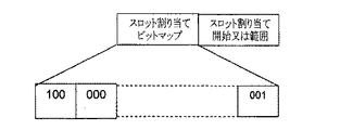
図16乃至図21は、一実施形態によるグループ接続を可能にするために要求されるグループ情報要素(Information Element:IE)を示す。 16 to 21 illustrate a group information element (IE) required to enable group connection according to an embodiment.
グループIEは、グループ接続要求、グループ接続応答、TDMA基盤のチャンネルアクセスメカニズムのためのブロードキャストメッセージでのグループ情報に対するグループIEを可能にする情報要素である。図16に示すように、上記情報用IEは、要素タイプフィールドを用いて識別される。長さフィールドは、グループIEの長さを提供する。 The group IE is an information element that enables group IE for group information in a broadcast message for a group connection request, a group connection response, and a TDMA-based channel access mechanism. As shown in FIG. 16, the information IE is identified using an element type field. The length field provides the length of the group IE.
グループ接続IEは、多くのノードカウントフィールドとグループ識別子を有する。一部の実施形態において、一つのフラグは、固有セキュリティキーとグループセキュリティキーのうちの一つであるセキュリティキー識別子を指示するために導入される。 The group connection IE has a number of node count fields and a group identifier. In some embodiments, a flag is introduced to indicate a security key identifier that is one of a unique security key and a group security key.
グループ接続要求に対する応答と共にコーディネータ装置からのブロードキャストメッセージとともに送信されるグループ応答IEは、要素タイプ、長さ、及び装置識別子を含むことができる。コーディネータ装置によってブロードキャスティングされたグループIEに対して、グループIEは、要素タイプ、長さ、グループ識別子、装置識別子、及びスロットプール(slot pool)情報を含む。グループIEに対する一部の実施形態において、装置識別子は、グループデバイスビットマップによって代替できる。グループIEに対する他の実施形態で、装置識別子は存在せず、デバイススロット割り当ては明示的スロット割り当てビットマップによって指示できる。 The group response IE sent with the broadcast message from the coordinator device along with the response to the group connection request may include the element type, length, and device identifier. For a group IE broadcast by a coordinator device, the group IE includes an element type, a length, a group identifier, a device identifier, and slot pool information. In some embodiments for group IEs, the device identifier can be replaced by a group device bitmap. In other embodiments for group IEs, there is no device identifier and device slot assignment can be indicated by an explicit slot assignment bitmap.
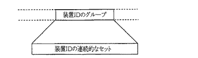
図17で、スロット割り当ての範囲はデバイスに対して定義される。一実施形態において、スロット割り当ては、TDMAに基づいて連続的であり得る。他の実施形態において、スロット割り当ては、TDMAに基づいて非連続的であり得る。 In FIG. 17, the slot allocation range is defined for a device. In one embodiment, the slot assignment may be continuous based on TDMA. In other embodiments, slot assignment may be non-contiguous based on TDMA.
図18で、グループの識別子は、連続的なセットの装置識別子として定義される。 In FIG. 18, the group identifier is defined as a continuous set of device identifiers.
図19で、コーディネータ装置により割り当てられたグループの識別子は非連続的である。 In FIG. 19, the group identifiers assigned by the coordinator device are non-contiguous.
図20で、デバイスがコーディネータ装置によってスロットが提供されるかを指示するデバイスビットマップが提供される。例えば、デバイスビットマップフィールドでのビット0が可能であると、デバイスグループの第1のデバイスは上記スロットが提供される。ビット1は、コーディネータ装置によってデバイスグループにスロットが提供されることを示すためにリセットされる。
In FIG. 20, a device bitmap is provided that indicates whether a device is provided with a slot by a coordinator device. For example, if
デバイスグループのうち一つのデバイスは異なる数のスロットが割り当てられる場合、デバイスは、図21に示すようにスロット割り当てビットマップを用いて定義されることがある。スロット割り当てビットマップは、コーディネータ装置にスロットが提供されるデバイスに対する情報を含む。例えば、100は、4個のスロットが第1のデバイスに対して提供されることを示す。同様に、スロットは、コーディネータ装置によってスロットが割り当てられたデバイスに対して定義される。 If a device in a device group is assigned a different number of slots, the device may be defined using a slot assignment bitmap as shown in FIG. The slot assignment bitmap contains information for the device in which the slot is provided to the coordinator device. For example, 100 indicates that 4 slots are provided for the first device. Similarly, a slot is defined for a device that has been assigned a slot by a coordinator device.
一部の実施形態において、デバイスビットマップとスロット割り当てビットマップは、図22に示すように、単一フィールド‘明示的スロット割り当てビットマップ’として表示可能である。図22で、第1のデバイスは、100により定義される4個のスロットを有する。第2のデバイスは、000により定義される0スロットを有することができる。 In some embodiments, the device bitmap and slot assignment bitmap can be displayed as a single field 'explicit slot assignment bitmap' as shown in FIG. In FIG. 22, the first device has four slots defined by 100. The second device may have 0 slots defined by 000.
以上、本発明の詳細な説明においては具体的な実施形態に関して説明したが、特許請求の範囲を外れない限り、様々な変更が可能であることは、当該技術分野における通常の知識を持つ者には明らかである。したがって、本発明の範囲は、前述の実施形態に限定されるものではなく、特許請求の範囲の記載及びこれと均等なものに基づいて定められるべきである。 As mentioned above, in the detailed description of the present invention, specific embodiments have been described. However, it is understood by those skilled in the art that various modifications can be made without departing from the scope of the claims. Is clear. Therefore, the scope of the present invention should not be limited to the above-described embodiments, but should be determined based on the description of the scope of claims and equivalents thereof.
100 環境
105 コーディネータ装置
110a,110b インプラント装置(IMD)
115a,115b オンボディ装置(OBD)
205 バス
210 プロセッサ
215 メモリ
220 ROM(Read Only Memory)
225 格納部
230 ディスプレイ
235 入力装置
240 カーソル制御器
245 通信インターフェース
100
115a, 115b On-body device (OBD)
205
225
Claims (38)
MICSチャンネルを獲得するステップと、
非MICSチャンネルを用いてウェイクアップを指示するウェイクアップ信号を送信するステップと、
前記ウェイクアップ信号を受信したインプラント装置を前記MICSチャンネルで接続するステップと、
前記インプラント装置とデータを交換するステップと、
前記インプラント装置に分離命令メッセージを伝送して接続を解除するステップと、
を有し、
前記ウェイクアップ信号は、前記獲得されたMICSチャンネルに対する情報を含むことを特徴とする方法。 A method of managing a plurality of implant devices using a coordinator device in a body area network,
Acquiring a MICS channel;
Transmitting a wake-up signal indicating wake-up using a non-MICS channel;
Connecting the implant device that has received the wake-up signal with the MICS channel;
Exchanging data with the implant device;
And releasing the connection by transmitting a separate instruction message to the implant device,
I have a,
The method according to claim 1, wherein the wake-up signal includes information on the acquired MICS channel .
前記ウェイクアップ信号を受信したインプラント装置から第1の承認信号を前記MICSチャンネルで受信するステップと、
前記承認信号に基づいて、接続を指示する命令信号を前記MICSチャンネルで前記インプラント装置に送信するステップと、
前記命令信号に基づいた第2の承認信号を前記MICSチャンネルで前記インプラント装置から受信するステップと、
を有することを特徴とする請求項1に記載の方法。 The connecting step includes:
Receiving a first acknowledgment signal on the MICS channel from an implant device that has received the wake-up signal;
Transmitting a command signal instructing connection to the implant device on the MICS channel based on the approval signal;
Receiving a second acknowledgment signal based on the command signal from the implant device on the MICS channel;
The method of claim 1 , comprising:
前記接続するステップは、
前記セキュリティ制御フィールドに基づいてセキュリティ手順を開始して前記インプラント装置を認証するステップと、
前記認証に基づいて暗号化及び復号化の中の一つを遂行するステップと、
再生保護を実行するステップと、
データフレームに対するインテグリティ保護を実行するステップと、
をさらに有することを特徴とする請求項2に記載の方法。 The second acknowledgment signal includes a security control field;
The connecting step includes:
Initiating a security procedure based on the security control field to authenticate the implant device;
Performing one of encryption and decryption based on the authentication; and
Performing replay protection; and
Performing integrity protection on the data frame; and
The method of claim 2 , further comprising:
接続を指示する命令信号を前記MICSチャンネルで前記インプラント装置に送信するステップと、
前記命令信号に基づいて承認信号を前記MICSチャンネルで前記インプラント装置から受信するステップと、
を有することを特徴とする請求項1に記載の方法。 The connecting step includes:
Transmitting a command signal indicating a connection to the implant device over the MICS channel;
Receiving an acknowledgment signal from the implant device on the MICS channel based on the command signal;
The method of claim 1 , comprising:
前記接続するステップは、
前記セキュリティ制御フィールドに基づいてセキュリティ手順を開始して前記インプラント装置を認証するステップと、
前記認証に基づいて暗号化及び復号化の中の一つを遂行するステップと、
再生保護を実行するステップと、
データフレームに対するインテグリティ保護を実行するステップと、
をさらに有することを特徴とする請求項4に記載の方法。 The approval signal includes a security control field;
The connecting step includes:
Initiating a security procedure based on the security control field to authenticate the implant device;
Performing one of encryption and decryption based on the authentication; and
Performing replay protection; and
Performing integrity protection on the data frame; and
The method of claim 4 further comprising:
定義された周期内で前記承認信号が前記インプラント装置から受信されるまで前記非MICSチャンネルで前記信号を再送信するステップと、
定義された期間で前記承認信号が前記MICSで受信されないと、他の非MICSチャンネルで前記ウェイクアップ信号を再送信するステップのうちいずれか一つを有することを特徴とする請求項2に記載の方法。 Transmitting the wake-up signal comprises:
Retransmitting the signal on the non-MICS channel until the acknowledgment signal is received from the implant device within a defined period;
The method of claim 2 , further comprising: retransmitting the wake-up signal on another non-MICS channel when the acknowledgment signal is not received by the MICS within a defined period. Method.
前記他のインプラント装置から前記非常信号が受信される場合に、前記インプラント装置との前記データ交換を中止し、前記他のインプラント装置とデータを交換するステップと、
をさらに含むことを特徴とする請求項1に記載の方法。 Scanning other MICS channels with the coordinator device for emergency signals transmitted from other implant devices;
Stopping said data exchange with said implant device and exchanging data with said other implant device when said emergency signal is received from said other implant device;
The method of claim 1 further comprising:
特定のオンボディ装置から前記コーディネータ装置情報に対する要求を受信するステップと、
前記オンボディ装置からピコネットとの結合に対する接続要求を受信するステップと、
前記コーディネータ装置のために定義される複数の許可制御パラメータに基づいて前記接続要求を確認するステップと、
前記接続要求を前記確認に基づいて承認するステップと、
前記接続要求に含まれるセキュリティ制御フィールドに基づいてセキュリティ手順を開始するステップと、
前記特定のオンボディ装置とデータを交換するステップと、
をさらに有することを特徴とする請求項1に記載の方法。 Acquiring a communication channel for communicating with an on-body device;
Receiving a request for the coordinator device information from a particular on-body device;
Receiving a connection request for coupling with a piconet from the on-body device;
Confirming the connection request based on a plurality of admission control parameters defined for the coordinator device;
Approving the connection request based on the confirmation;
Initiating a security procedure based on a security control field included in the connection request;
Exchanging data with the specific on-body device;
The method of claim 1, further comprising:
前記特定のオンボディ装置を認証するステップ、前記認証に基づいて暗号化及び復号化の中の一つを遂行するステップ、再生保護を実行するステップ、及びデータフレームに対してインテグリティ保護を可能にするステップのうちいずれか一つを有することを特徴とする請求項12に記載の方法。 Initiating the security procedure comprises:
Authenticating the particular on-body device, performing one of encryption and decryption based on the authentication, performing playback protection, and enabling integrity protection for the data frame The method of claim 12 , comprising any one of the steps.
前記コーディネータ装置情報をブロードキャスティングするステップと、
前記ブロードキャスティングに基づいて前記特定のオンボディ装置から前記接続要求を受信するステップと、をさらに有することを特徴とする請求項1に記載の方法。 Obtaining a communication channel for communicating with the on-body device;
Broadcasting the coordinator device information;
The method of claim 1, further comprising receiving the connection request from the specific on-body device based on the broadcasting.
前記通信チャンネルの占有を指示する通知をブロードキャスティングするステップと、
前記通知に基づいて応答を決定するステップと、
を有することを特徴とする請求項12に記載の方法。 Acquiring the communication channel comprises:
Broadcasting a notification indicating occupation of the communication channel;
Determining a response based on the notification;
The method of claim 12 , comprising:
前記一つ又はそれ以上の代表ノードの中で代表ノードから受諾される前記接続要求を受信することに基づいて前記接続要求を管理するステップと、
メッセージを前記複数のオンボディ装置にブロードキャスティングするステップと、を有し、
前記メッセージは、前記代表ノードに対応するグループ識別子、前記複数のオンボディ装置に対する装置識別子、及び1セットのセキュリティパラメータのうち少なくとも一つを含むことを特徴とする請求項12に記載の方法。 Receiving a connection request from each representative node among one or more representative nodes representing the plurality of on-body devices;
Managing the connection request based on receiving the connection request accepted from a representative node among the one or more representative nodes;
Broadcasting a message to the plurality of on-body devices;
The method of claim 12 , wherein the message includes at least one of a group identifier corresponding to the representative node, a device identifier for the plurality of on-body devices, and a set of security parameters.
前記コーディネータ装置と前記複数のオンボディ装置との間で共有されるマスターキー識別子と、
コーディネータノンスと、
クライアントノンスと、
固有個別キーと共通キーのうちいずれか一つを指示するフラグビットと、
を含むことを特徴とする請求項19に記載の方法。 The set of security parameters is
A master key identifier shared between the coordinator device and the plurality of on-body devices;
With coordinator nonce,
With client nonce,
A flag bit indicating one of a unique individual key and a common key;
20. The method of claim 19 , comprising:
前記マスターキー識別子、前記コーディネータノンス、及び前記クライアントノンスを用いて前記コーディネータ装置と複数のオンボディ装置との間で共通ペアワイズキーを生成するステップのうちいずれか一つをさらに有することを特徴とする請求項23に記載の方法。 Generating a unique pairwise key between the coordinator device and each on-body device using the master key identifier, the coordinator nonce, the client nonce, and the device identifier of each on-body device;
The method further comprises any one of steps of generating a common pairwise key between the coordinator device and a plurality of on-body devices using the master key identifier, the coordinator nonce, and the client nonce. 24. The method of claim 23 .
通信インターフェースと、
前記通信インターフェースを通じて、MICSチャンネルを獲得し、非MICSチャンネルを用いてウェイクアップを指示するウェイクアップ信号を送信し、前記ウェイクアップ信号を受信したインプラント装置を前記MICSチャンネルで接続し、前記インプラント装置とデータを交換し、前記インプラント装置で分離命令メッセージを伝送して接続を解除するプロセッサと、
前記交換されたデータを格納する格納装置と、
を含み、
前記ウェイクアップ信号は、前記獲得されたMICSチャンネルに対する情報を含むことを特徴とする装置。 A coordinator device that manages the body area network,
A communication interface;
The MICS channel is acquired through the communication interface, a wake-up signal instructing wake-up is transmitted using a non-MICS channel, the implant device that has received the wake-up signal is connected to the MICS channel, and the implant device A processor for exchanging data and transmitting a disconnect command message with the implant device to disconnect;
A storage device for storing the exchanged data;
Only including,
The apparatus of claim 1, wherein the wake-up signal includes information on the acquired MICS channel .
前記インプラント装置を接続するために、前記ウェイクアップ信号を受信したインプラント装置から第1の承認信号を前記MICSチャンネルで受信し、前記承認信号に基づいて接続を指示する命令信号を前記MICSチャンネルで前記インプラント装置に送信し、
前記命令信号に基づいた第2の承認信号を前記MICSチャンネルで前記インプラント装置から受信することを特徴とする請求項26に記載の装置。 The processor is
In order to connect the implant device, a first approval signal is received on the MICS channel from the implant device that has received the wake-up signal, and a command signal that instructs connection based on the approval signal is received on the MICS channel. Send to the implant device,
27. The device of claim 26 , wherein a second acknowledgment signal based on the command signal is received from the implant device over the MICS channel.
前記プロセッサは、
前記セキュリティ制御フィールドに基づいてセキュリティ手順を開始して前記インプラント装置を認証し、前記認証に基づいて暗号化及び復号化の中の一つを遂行し、
再生保護を実行し、
データフレームに対するインテグリティ保護を実行することを特徴とする請求項27に記載の装置。 The second acknowledgment signal includes a security control field;
The processor is
Initiating a security procedure based on the security control field to authenticate the implant device, performing one of encryption and decryption based on the authentication,
Run playback protection,
28. The apparatus of claim 27 , performing integrity protection for data frames.
前記インプラント装置を接続するために、接続を指示する命令信号を前記MICSチャンネルで前記インプラント装置に送信し、
前記命令信号に基づいた承認信号を前記MICSチャンネルで前記インプラント装置から受信することを特徴とする請求項26に記載の装置。 The processor is
In order to connect the implant device, a command signal instructing connection is transmitted to the implant device through the MICS channel,
27. The device of claim 26 , wherein an approval signal based on the command signal is received from the implant device over the MICS channel.
前記プロセッサは、
前記セキュリティ制御フィールドに基づいてセキュリティ手順を開始して前記インプラント装置を認証し、
前記認証に基づいて暗号化及び復号化の中の一つを遂行し、
前記再生保護を実行し、
データフレームに対するインテグリティ保護を実行することを特徴とする請求項29に記載の装置。 The approval signal includes a security control field;
The processor is
Initiating a security procedure based on the security control field to authenticate the implant device;
Performing one of encryption and decryption based on the authentication;
Performing the replay protection,
30. The apparatus of claim 29 , performing integrity protection for data frames.
前記通信インターフェースを通じて、オンボディ装置と通信を遂行するための通信チャンネルを獲得し、特定のオンボディ装置から前記コーディネータ装置情報に対する要求を受信し、前記オンボディ装置からピコネットとの接続に対する接続要求を受信し、前記コーディネータ装置のために定義される複数の許可制御パラメータに基づいて前記接続要求を確認し、
前記確認に基づいて前記接続要求を承認し、前記接続要求に含まれたセキュリティ制御フィールドに基づいてセキュリティ手順を開始し、前記特定のオンボディ装置とデータを交換することを特徴とする請求項26に記載の装置。 The processor is
A communication channel for performing communication with an on-body device is acquired through the communication interface, a request for the coordinator device information is received from a specific on-body device, and a connection request for connection with the piconet is received from the on-body device. Receiving and confirming the connection request based on a plurality of admission control parameters defined for the coordinator device;
Claim 26, wherein checking the connection request approved based on, to start the security procedures based on the security control field included in the connection request, and wherein the exchange of the specific on the body device and the data The device described in 1.
前記メッセージは、前記代表ノードに対応するグループ識別子、前記複数のオンボディ装置に対する装置識別子、及びワンセットのセキュリティパラメータのうち少なくとも一つを含むことを特徴とする請求項26に記載の装置。 The processor receives a connection request from each representative node of one or more representative nodes, the one or more representative nodes represent a plurality of on-body devices, and receives the connection request. Managing the connection request based on, the connection request from a representative node of the one or more representative nodes is accepted, and broadcasting a message to the plurality of on-body devices;
The apparatus of claim 26 , wherein the message includes at least one of a group identifier corresponding to the representative node, a device identifier for the plurality of on-body devices, and a set of security parameters.
非MICSチャンネルを介してコーディネータ装置からウェイクアップ信号を受信するステップと、
前記ウェイクアップ信号の受信によってMICSチャンネル機能を活性化するステップと、
前記ウェイクアップ信号に含まれたMICSチャンネルの情報を用いてコーディネータ装置と前記MICSチャンネルで前記コーディネータ装置に接続するステップと、
前記コーディネータ装置とデータを交換するステップと、
を有することを特徴とする方法。 A method for an implant device to support a body area network comprising:
Receiving a wake-up signal from a coordinator device via a non-MICS channel;
Activating a MICS channel function upon receipt of the wake-up signal;
Using the MICS channel information included in the wake-up signal to connect to the coordinator device and the coordinator device via the MICS channel;
Exchanging data with the coordinator device;
A method characterized by comprising:
前記ウェイクアップ信号に基づいて第1の承認信号を前記コーディネータ装置に伝送するステップと、
前記承認信号に関連して、前記コーディネータ装置への接続を指示する命令信号を前記コーディネータ装置から受信するステップと、
前記命令信号に基づいて第2の承認信号を前記コーディネータ装置に伝送するステップと、
を有することを特徴とする請求項36に記載の方法。 The connecting step includes:
Transmitting a first acknowledgment signal to the coordinator device based on the wake-up signal;
Receiving, from the coordinator device, a command signal instructing connection to the coordinator device in relation to the approval signal;
Transmitting a second acknowledgment signal to the coordinator device based on the command signal;
37. The method of claim 36 , comprising:
前記ウェイクアップ信号の受信後に、前記コーディネータ装置への接続を指示する命令信号を前記コーディネータ装置から受信するステップと、
前記命令信号に基づいて承認信号を前記コーディネータ装置に伝送するステップと、
を有することを特徴とする請求項36に記載の方法。 The connecting step includes:
After receiving the wake-up signal, receiving a command signal for instructing connection to the coordinator device from the coordinator device;
Transmitting an approval signal to the coordinator device based on the command signal;
37. The method of claim 36 , comprising:
Applications Claiming Priority (5)
| Application Number | Priority Date | Filing Date | Title |
|---|---|---|---|
| IN1014CH2009 | 2009-04-30 | ||
| IN1014/CHE/2009 | 2009-04-30 | ||
| IN2605CH2009 | 2009-10-26 | ||
| IN2605/CHE/2008 | 2009-10-26 | ||
| PCT/KR2010/002780 WO2010126342A2 (en) | 2009-04-30 | 2010-04-30 | Method and system for managing a body area network using a coordinator device |
Publications (2)
| Publication Number | Publication Date |
|---|---|
| JP2012525762A JP2012525762A (en) | 2012-10-22 |
| JP5259014B2 true JP5259014B2 (en) | 2013-08-07 |
Family
ID=45541553
Family Applications (1)
| Application Number | Title | Priority Date | Filing Date |
|---|---|---|---|
| JP2012508406A Expired - Fee Related JP5259014B2 (en) | 2009-04-30 | 2010-04-30 | Method and system for managing a body area network using a coordinator device |
Country Status (8)
| Country | Link |
|---|---|
| US (1) | US8964662B2 (en) |
| EP (1) | EP2425587A4 (en) |
| JP (1) | JP5259014B2 (en) |
| KR (1) | KR20120026077A (en) |
| AU (1) | AU2010242140B2 (en) |
| CA (2) | CA2889774C (en) |
| RU (1) | RU2490808C1 (en) |
| WO (1) | WO2010126342A2 (en) |
Families Citing this family (36)
| Publication number | Priority date | Publication date | Assignee | Title |
|---|---|---|---|---|
| US8897217B2 (en) * | 2009-12-09 | 2014-11-25 | Texas Instruments Incorporated | Address space partitioning and filtering for discretionary wireless connection response |
| US8565109B1 (en) | 2010-01-29 | 2013-10-22 | University Of Washington Through Its Center Of Commercialization | Optimization of polling protocols in sensor networks |
| US9113473B2 (en) * | 2011-04-06 | 2015-08-18 | Spinal Modulation, Inc. | Power efficient wireless RF communication between a base station and a medical device |
| US20130027186A1 (en) * | 2011-07-26 | 2013-01-31 | Can Cinbis | Ultralow-power implantable hub-based wireless implantable sensor communication |
| KR101263636B1 (en) * | 2011-09-01 | 2013-05-10 | 경희대학교 산학협력단 | Implanted body sensor network |
| US9538337B2 (en) * | 2012-08-09 | 2017-01-03 | Genesys Telecommunications Laboratories, Inc. | System and method for communication spread across multiple physical layer channels |
| JP2013123211A (en) * | 2011-11-10 | 2013-06-20 | Canon Inc | Communication device and control method of communication device |
| US9098610B2 (en) | 2011-12-22 | 2015-08-04 | Greatbatch Ltd. | Communication for implantable medical devices |
| EP2884887B1 (en) * | 2012-08-16 | 2016-10-12 | Koninklijke Philips N.V. | Coordinator switching method for medical body area networks |
| US20140214940A1 (en) * | 2013-01-31 | 2014-07-31 | Sony Corporation | Networked devices matching capabilities with tasks |
| KR101877658B1 (en) * | 2013-12-13 | 2018-07-11 | 인텔 코포레이션 | Techniques for securing body-based communications |
| US9641488B2 (en) * | 2014-02-28 | 2017-05-02 | Dropbox, Inc. | Advanced security protocol for broadcasting and synchronizing shared folders over local area network |
| EP3149872B1 (en) | 2014-05-27 | 2018-03-28 | Koninklijke Philips N.V. | Body coupled communication device with synchronization |
| JP2017528053A (en) * | 2014-07-30 | 2017-09-21 | 株式会社東芝 | Configuration of MAC parameters in body area networks |
| US10375081B2 (en) * | 2014-08-13 | 2019-08-06 | Intel Corporation | Techniques and system for extended authentication |
| US10284386B2 (en) * | 2014-08-28 | 2019-05-07 | Maxlinear, Inc. | Method and apparatus for providing a high security mode in a network |
| US10481666B2 (en) * | 2015-04-30 | 2019-11-19 | Samsung Electronics Co., Ltd. | Method and system for optimizing communication in a heterogeneous network |
| US10129220B2 (en) | 2015-06-13 | 2018-11-13 | Avocado Systems Inc. | Application and data protection tag |
| US10397277B2 (en) | 2015-06-14 | 2019-08-27 | Avocado Systems Inc. | Dynamic data socket descriptor mirroring mechanism and use for security analytics |
| US10193889B2 (en) | 2015-06-14 | 2019-01-29 | Avocado Systems Inc. | Data socket descriptor attributes for application discovery in data centers |
| US10270810B2 (en) | 2015-06-14 | 2019-04-23 | Avocado Systems Inc. | Data socket descriptor based policies for application and data behavior and security |
| US10148697B2 (en) | 2015-06-16 | 2018-12-04 | Avocado Systems Inc. | Unified host based security exchange between heterogeneous end point security agents |
| US10193930B2 (en) * | 2015-06-29 | 2019-01-29 | Avocado Systems Inc. | Application security capability exchange via the application and data protection layer |
| US10356068B2 (en) | 2015-07-14 | 2019-07-16 | Avocado Systems Inc. | Security key generator module for security sensitive applications |
| US10354070B2 (en) | 2015-08-22 | 2019-07-16 | Avocado Systems Inc. | Thread level access control to socket descriptors and end-to-end thread level policies for thread protection |
| US10230491B2 (en) | 2015-12-15 | 2019-03-12 | General Electric Company | System and method for communication in a body area network system |
| JP6884600B2 (en) | 2017-03-02 | 2021-06-09 | 任天堂株式会社 | Wireless communication system, communication method, information processing device, and information processing program |
| JP6979740B2 (en) | 2017-03-02 | 2021-12-15 | 任天堂株式会社 | Wireless communication system, communication method, information processing device, and information processing program |
| JP6895273B2 (en) * | 2017-03-02 | 2021-06-30 | 任天堂株式会社 | Information processing equipment, information processing programs, wireless communication systems, and communication methods |
| WO2019005942A1 (en) * | 2017-06-28 | 2019-01-03 | Intel Corporation | Wake-up frame protection |
| US20190372973A1 (en) * | 2018-05-30 | 2019-12-05 | Cisco Technology, Inc. | Device onboarding with automatic ipsk provisioning in wireless networks |
| US11522919B2 (en) | 2019-01-31 | 2022-12-06 | Medtronic, Inc. | Establishing a secure communication link |
| US11696129B2 (en) | 2019-09-13 | 2023-07-04 | Samsung Electronics Co., Ltd. | Systems, methods, and devices for association and authentication for multi access point coordination |
| FI129163B (en) * | 2020-06-10 | 2021-08-13 | Wirepas Oy | Timetable planning system of resources for a wireless data communication network |
| CN112604160B (en) * | 2020-12-11 | 2024-05-28 | 景昱医疗科技(苏州)股份有限公司 | Method and system for solving channel interference of in vitro programmer |
| WO2024062312A1 (en) * | 2022-09-21 | 2024-03-28 | Cochlear Limited | Wireless ecosystem for a medical device |
Family Cites Families (8)
| Publication number | Priority date | Publication date | Assignee | Title |
|---|---|---|---|---|
| US7103344B2 (en) * | 2000-06-08 | 2006-09-05 | Menard Raymond J | Device with passive receiver |
| US7280872B1 (en) | 2003-10-16 | 2007-10-09 | Transoma Medical, Inc. | Wireless communication with implantable medical device |
| DE102005008627A1 (en) | 2005-02-25 | 2006-08-31 | Raumedic Ag | Sensor system for measuring, transmitting, processing and displaying physiological parameters of patient, has expansion module connected via wireless telemetry path to sensor or additional sensor |
| US7660630B2 (en) * | 2006-04-27 | 2010-02-09 | Medtronic, Inc. | Variable implantable medical device power characteristics based upon implant depth |
| US7623922B2 (en) * | 2006-07-12 | 2009-11-24 | Cardiac Pacemakers, Inc. | Implantable medical device telemetry with periodic frequency hopping |
| US20100151113A1 (en) * | 2008-12-12 | 2010-06-17 | Microchips, Inc. | Manufacture of a radiating structure for a medical implant |
| US8943305B2 (en) * | 2009-01-30 | 2015-01-27 | Texas Instruments Incorporated | Frame structure for medium access in body area networks (BAN) |
| EP2227063B1 (en) * | 2009-03-04 | 2012-03-14 | Fujitsu Limited | Improvements to wireless sensor networks |
-
2010
- 2010-04-30 CA CA2889774A patent/CA2889774C/en not_active Expired - Fee Related
- 2010-04-30 US US13/318,284 patent/US8964662B2/en not_active Expired - Fee Related
- 2010-04-30 JP JP2012508406A patent/JP5259014B2/en not_active Expired - Fee Related
- 2010-04-30 KR KR1020117028708A patent/KR20120026077A/en not_active Abandoned
- 2010-04-30 AU AU2010242140A patent/AU2010242140B2/en not_active Ceased
- 2010-04-30 WO PCT/KR2010/002780 patent/WO2010126342A2/en not_active Ceased
- 2010-04-30 CA CA2760668A patent/CA2760668C/en not_active Expired - Fee Related
- 2010-04-30 RU RU2011148636/08A patent/RU2490808C1/en not_active IP Right Cessation
- 2010-04-30 EP EP10769987.8A patent/EP2425587A4/en not_active Withdrawn
Also Published As
| Publication number | Publication date |
|---|---|
| RU2490808C1 (en) | 2013-08-20 |
| US8964662B2 (en) | 2015-02-24 |
| US20120051314A1 (en) | 2012-03-01 |
| AU2010242140A1 (en) | 2011-12-22 |
| EP2425587A2 (en) | 2012-03-07 |
| CA2760668A1 (en) | 2010-11-04 |
| CA2889774A1 (en) | 2010-11-04 |
| JP2012525762A (en) | 2012-10-22 |
| CA2889774C (en) | 2018-04-03 |
| RU2011148636A (en) | 2013-06-10 |
| CN102804695A (en) | 2012-11-28 |
| AU2010242140A8 (en) | 2012-01-12 |
| CA2760668C (en) | 2016-06-07 |
| WO2010126342A3 (en) | 2011-01-13 |
| AU2010242140B2 (en) | 2014-01-16 |
| KR20120026077A (en) | 2012-03-16 |
| WO2010126342A2 (en) | 2010-11-04 |
| EP2425587A4 (en) | 2014-11-05 |
Similar Documents
| Publication | Publication Date | Title |
|---|---|---|
| JP5259014B2 (en) | Method and system for managing a body area network using a coordinator device | |
| US10536856B2 (en) | Communication control apparatus, system, and method therefor | |
| EP2326114B1 (en) | Method and apparatus for forming security channel in short range communication | |
| US9438332B2 (en) | Low cost proximity pairing mechanism in wireless personal area networks | |
| EP1742422B1 (en) | Wireless communication apparatus | |
| US8959601B2 (en) | Client configuration during timing window | |
| CN107409145A (en) | Method, device and computer program product for local control via middleware | |
| US20170034861A1 (en) | Communication apparatus and communication parameter configuration method thereof | |
| US20170372600A1 (en) | Method, apparatus, and computer program product for local control through intermediate device | |
| US20110230139A1 (en) | Communication apparatus and method for wi-fi protected setup in adhoc network | |
| JP2019526980A (en) | System and method for waking up a station safely and quickly | |
| US10484363B2 (en) | Method and apparatus for authenticating a device using Bluetooth technology | |
| US20180091633A1 (en) | Wireless communication apparatus and processing method thereby | |
| US10887762B2 (en) | Method and apparatus for transmitting and receiving data using Bluetooth technology | |
| KR20220161044A (en) | Method and apparatus for configuring mac (media access control) address for uwb (ultra wide band) communication | |
| US8861492B2 (en) | Method for communication between a WLAN terminal and a human interface device | |
| CN102804695B (en) | For using the method and system of coordinator unit management body area network | |
| US20230299954A1 (en) | Secure provisioning of communications channels | |
| KR20230097649A (en) | Method for transmitting and receiving medical data using BLE and device supporting the same |
Legal Events
| Date | Code | Title | Description |
|---|---|---|---|
| A131 | Notification of reasons for refusal |
Free format text: JAPANESE INTERMEDIATE CODE: A131 Effective date: 20121204 |
|
| A521 | Request for written amendment filed |
Free format text: JAPANESE INTERMEDIATE CODE: A523 Effective date: 20130301 |
|
| TRDD | Decision of grant or rejection written | ||
| A01 | Written decision to grant a patent or to grant a registration (utility model) |
Free format text: JAPANESE INTERMEDIATE CODE: A01 Effective date: 20130326 |
|
| A61 | First payment of annual fees (during grant procedure) |
Free format text: JAPANESE INTERMEDIATE CODE: A61 Effective date: 20130423 |
|
| FPAY | Renewal fee payment (event date is renewal date of database) |
Free format text: PAYMENT UNTIL: 20160502 Year of fee payment: 3 |
|
| R150 | Certificate of patent or registration of utility model |
Ref document number: 5259014 Country of ref document: JP Free format text: JAPANESE INTERMEDIATE CODE: R150 Free format text: JAPANESE INTERMEDIATE CODE: R150 |
|
| R250 | Receipt of annual fees |
Free format text: JAPANESE INTERMEDIATE CODE: R250 |
|
| R250 | Receipt of annual fees |
Free format text: JAPANESE INTERMEDIATE CODE: R250 |
|
| R250 | Receipt of annual fees |
Free format text: JAPANESE INTERMEDIATE CODE: R250 |
|
| LAPS | Cancellation because of no payment of annual fees |