JP5257276B2 - Manipulation system drive method - Google Patents
Manipulation system drive method Download PDFInfo
- Publication number
- JP5257276B2 JP5257276B2 JP2009156763A JP2009156763A JP5257276B2 JP 5257276 B2 JP5257276 B2 JP 5257276B2 JP 2009156763 A JP2009156763 A JP 2009156763A JP 2009156763 A JP2009156763 A JP 2009156763A JP 5257276 B2 JP5257276 B2 JP 5257276B2
- Authority
- JP
- Japan
- Prior art keywords
- injection
- target cell
- image
- holding member
- sample
- Prior art date
- Legal status (The legal status is an assumption and is not a legal conclusion. Google has not performed a legal analysis and makes no representation as to the accuracy of the status listed.)
- Active
Links
Images


Classifications
-
- C—CHEMISTRY; METALLURGY
- C12—BIOCHEMISTRY; BEER; SPIRITS; WINE; VINEGAR; MICROBIOLOGY; ENZYMOLOGY; MUTATION OR GENETIC ENGINEERING
- C12M—APPARATUS FOR ENZYMOLOGY OR MICROBIOLOGY; APPARATUS FOR CULTURING MICROORGANISMS FOR PRODUCING BIOMASS, FOR GROWING CELLS OR FOR OBTAINING FERMENTATION OR METABOLIC PRODUCTS, i.e. BIOREACTORS OR FERMENTERS
- C12M35/00—Means for application of stress for stimulating the growth of microorganisms or the generation of fermentation or metabolic products; Means for electroporation or cell fusion
Description
本発明は、細胞を操作するマニピュレーションシステム駆動方法に関するものである。 The present invention relates to luma two population system driving method to operate the cell.
バイオテクノロジの分野では、微小な対象物に微細な操作を行う、細胞や胚にDNAを注入するDNAマイクロインジェクション、卵に精子を注入するICSI(卵細胞質内精子注入法)、体外で卵細胞を受精させる体外授精、体細胞に他の細胞の核を移植する体細胞核移植、細胞の内部細胞塊を取り出す内部細胞塊単離などがある。特にICSI、体細胞核移植、内部細胞塊単離では、細胞の内部に物質を注入させたり、細胞の内部の物体を取り出したりするために、細胞、卵の膜に穿孔を形成する。 In the field of biotechnology, micro manipulation of minute objects, DNA microinjection that injects DNA into cells and embryos, ICSI (intracytoplasmic sperm injection) that injects sperm into eggs, and in vitro fertilization of egg cells Examples include in vitro fertilization, somatic cell nuclear transfer in which the nuclei of other cells are transplanted into somatic cells, and isolation of the inner cell mass to extract the inner cell mass of the cell. In particular, in ICSI, somatic cell nuclear transfer, and inner cell mass isolation, a perforation is formed in the membrane of a cell or egg in order to inject a substance into the cell or take out an object inside the cell.
卵、細胞の膜に穿孔を形成する装置としては、例えば、特許文献1に、被検体と対物レンズとの位置を相対的に移動させ、この移動に応じて前記被検体に焦点の合う位置を検出し、この検出結果に基づいて、前記被検体移動手段の動作を制御することで、顕微鏡の視野内で被検体に対して微小針を用いて微細操作を行うマイクロマニピュレーションシステムが記載されている。 As an apparatus for forming a perforation in the membrane of an egg or cell, for example, in Patent Document 1, the positions of the subject and the objective lens are relatively moved, and the position where the subject is focused is determined according to this movement. A micromanipulation system is described in which a micromanipulation is performed using a microneedle on a subject within a field of view of a microscope by detecting and controlling the operation of the subject moving means based on the detection result. .
特許文献1に記載の装置のように、被検体、つまり、対象なる細胞に微小針を差し込むことで、穿孔を形成することができる。ここで、操作者は、対象細胞に穿孔を形成するために、視野内にある対象細胞を自ら発見し、所定位置まで移動させる必要がある。また、視野内に対象細胞がない場合は、被検体を保持しているステージか、撮影領域を移動させて、視野を移動させつつ、対象細胞を探す必要がある。そのため、操作する者の熟練度によっては、操作に時間がかかったり、対象細胞の所望の位置に穿孔を形成できなかったりするという問題がある。 Like the apparatus described in Patent Document 1, a perforation can be formed by inserting a microneedle into a subject, that is, a target cell. Here, the operator needs to find the target cell in the field of view and move it to a predetermined position in order to form a perforation in the target cell. If there is no target cell in the field of view, it is necessary to move the field of view to the stage holding the subject or move the field of view to search for the target cell. Therefore, depending on the skill level of the operator, there is a problem that the operation takes time, or the perforation cannot be formed at a desired position of the target cell.
また、シャーレ上に複数の対象細胞を配置している場合は、既に穿孔を形成した対象細胞と、まだ穿孔を形成していない対象細胞とが混在するため、それらの細胞を判断する必要もあり、操作者の操作が煩雑になるという問題もある。 In addition, when multiple target cells are placed on a petri dish, target cells that have already been perforated and target cells that have not yet been perforated are mixed, so it is also necessary to determine those cells. There is also a problem that the operation of the operator becomes complicated.
本発明は、上記に鑑みてなされたものであって、操作者の熟練度、技術によらず、効率よくかつ好適に対象細胞を操作することができるマニピュレーションシステム駆動方法を提供することを目的とする。 The present invention was made in view of the above, the operator skill level, regardless of the technology, to provide an efficient and suitably can operate target cells luma two population system driving method For the purpose.
上述した課題を解決し、目的を達成するために、本発明は、微小な対象物を保持する試料保持部材が載置された試料ステージと、前記試料ステージを駆動する駆動部と、前記微小な対象物を操作するマニピュレータと、前記操作される微小な対象物の拡大像を観察する顕微鏡と、前記顕微鏡による拡大像を撮像する撮像部と、前記撮像部により撮像した画像を表示する表示部と、前記撮像部を用いて、前記試料保持部材の撮影対象領域を分割して撮影した複数の画像を取得し、取得した複数の画像を合成して撮影対象領域全体の画像を取得する画像合成手段を有する制御部と、を備えることを特徴とする。 In order to solve the above-described problems and achieve the object, the present invention provides a sample stage on which a sample holding member that holds a minute object is placed, a drive unit that drives the sample stage, and the minute A manipulator that operates an object; a microscope that observes an enlarged image of the minute object to be operated; an imaging unit that captures an enlarged image by the microscope; and a display unit that displays an image captured by the imaging unit; Image synthesizing means for acquiring a plurality of images obtained by dividing the imaging target area of the sample holding member using the imaging unit and synthesizing the acquired plurality of images to obtain an image of the entire imaging target area And a control unit having.
ここで、前記制御部は、取得した画像に撮影された対象細胞の位置を検出する位置検出手段と、検出された前記対象細胞の位置に基づいて、前記マニピュレータと前記対象細胞とを相対的に移動させる経路を設定する移動経路設定手段と、前記移動経路設定手段の設定に基づいて前記移動手段を操作し、前記対象細胞を前記マニピュレータにより操作する位置に移動させる動作制御手段と、を有することが好ましい。 Here, the control unit relatively detects the position of the target cell captured in the acquired image and the manipulator and the target cell based on the detected position of the target cell. A movement path setting unit that sets a path to be moved; and an operation control unit that operates the movement unit based on the setting of the movement path setting unit and moves the target cell to a position operated by the manipulator. Is preferred.
また、前記制御部は、前記試料ステージと前記顕微鏡との相対位置の基準位置を記憶することが好ましい。 The control unit preferably stores a reference position of a relative position between the sample stage and the microscope.
また、前記制御部は、前記試料ステージと前記顕微鏡との相対位置が、前記基準位置となるように、前記駆動部により前記試料ステージを移動させることが好ましい。 Further, it is preferable that the control unit moves the sample stage by the driving unit so that a relative position between the sample stage and the microscope becomes the reference position.
また、前記表示部は、前記画像合成部で取得した撮影対象領域全体の画像と、前記撮像部で取得した画像とを同時に表示させることが好ましい。 Moreover, it is preferable that the said display part displays simultaneously the image of the whole imaging | photography object area | region acquired with the said image synthetic | combination part, and the image acquired with the said imaging part.
また、前記マニピュレータは、前記試料保持部材に保持された前記試料の前記対象細胞を保持する細胞保持手段と、前記細胞保持手段に保持された前記対象細胞を加工する細胞加工手段と、を有することが好ましい。 Further, the manipulator includes cell holding means for holding the target cells of the sample held by the sample holding member, and cell processing means for processing the target cells held by the cell holding means. Is preferred.
上述した課題を解決し、目的を達成するために、本発明は、上記のいずれか1項に記載のマニピュレーションシステムにより、一定の処理領域に載置された前記対象細胞を操作するマニピュレーションシステム駆動方法であって、前記撮像部を用いて、前記試料保持部材の撮影対象領域を分割して撮影した複数の画像を取得し、取得した複数の画像を合成して撮影対象領域全体の画像を取得する画像取得ステップと、前記細胞保持手段及び前記細胞操作手段と前記試料保持部材とを相対的に移動させ、複数の前記対象細胞を、順次前記所定領域に搬送されるように移動させる相対移動ステップと、前記相対移動ステップで前記所定領域に前記対象細胞が搬送されたら、前記細胞保持手段により前記所定領域内の前記対象細胞を保持し、前記細胞保持手段に保持された対象細胞を前記細胞操作手段により操作する細胞操作ステップと、を有することを特徴とする。 In order to solve the above-described problems and achieve the object, the present invention provides a manipulation system driving method for manipulating the target cell placed in a certain processing region by the manipulation system according to any one of the above. And using the said imaging part, the some imaging | photography area | region of the said sample holding member is divided | segmented, the some image image | photographed is acquired, the acquired some image is synthesize | combined, and the image of the whole imaging | photography area | region is acquired. An image acquisition step, a relative movement step of relatively moving the cell holding means, the cell operation means, and the sample holding member to move the plurality of target cells so as to be sequentially conveyed to the predetermined region; When the target cell is transported to the predetermined area in the relative movement step, the target cell in the predetermined area is held by the cell holding means, and the cell The target cells held in the holding means and having a a cell manipulation step of manipulating by the cell manipulation means.
さらに、取得した画像から前記培地に含有される対象細胞の位置及び大きさを検出する対象細胞検出ステップと、前記検出した対象細胞の位置及び大きさから、前記細胞保持手段及び前記細胞操作手段と前記試料保持部材とを相対的に移動させて、複数の前記対象細胞を順次、前記処理領域に搬送する経路を算出し、設定する経路設定ステップを有し、前記相対移動ステップは、前記経路設定ステップで設定した経路で、前記細胞保持手段及び前記細胞操作手段と前記試料保持部材とを相対的に移動させることが好ましい。 Further, a target cell detection step for detecting the position and size of the target cell contained in the culture medium from the acquired image, and the cell holding means and the cell manipulation means from the detected position and size of the target cell, A path setting step of calculating and setting a path for sequentially transporting the plurality of target cells to the processing region by moving the sample holding member relative to each other; the relative movement step including the path setting; It is preferable that the cell holding means, the cell operation means, and the sample holding member are relatively moved along the path set in the step.
また、前記試料保持部材は、複数の前記対象細胞を単列上に配置した状態で保持していることが好ましい。 The sample holding member preferably holds a plurality of the target cells arranged in a single row.
また、前記細胞保持手段及び前記細胞操作手段は、それぞれ、3軸方向に移動する3軸移動機構と、前記3軸移動機構に連結され、前記細胞に対して直動する直動移動機構と、前記直動移動機構により移動され、細胞を処置する処置部とで構成され、前記細胞保持手段及び前記細胞操作手段は、前記移動手段に対する原点を設定する原点設定ステップを有し、前記細胞操作ステップは、前記原点設定ステップにより設定された原点に基づいて、前記細胞保持手段及び前記細胞操作手段のそれぞれの前記処置部を前記3軸移動機構により移動させた後、前記直動移動機構により前記処置部を直動方向に往復移動させて、前記対照細胞に処置を施すこと、順次複数の前記対象細胞に繰り返すことが好ましい。 Further, the cell holding means and the cell operation means are each a triaxial movement mechanism that moves in three axial directions, a linear movement mechanism that is connected to the triaxial movement mechanism and moves linearly with respect to the cells, The cell movement unit includes a treatment unit that is moved by the linear movement mechanism and treats cells, and the cell holding unit and the cell operation unit include an origin setting step for setting an origin with respect to the movement unit, and the cell operation step Based on the origin set in the origin setting step, the treatment sections of the cell holding means and the cell operation means are moved by the triaxial movement mechanism, and then the treatment is moved by the linear movement mechanism. It is preferable that the control cell is treated by reciprocating the part in the linear movement direction, and sequentially repeating the plurality of target cells.
また、前記試料保持部材と前記細胞保持手段との相対位置の基準位置を記憶する記憶ステップと、前記基準位置に移動させる指示が入力されたことを検出したら、前記記憶ステップで記憶した前記基準位置に前記試料ステージを移動させる移動ステップと、を有することが好ましい。 Further, when it is detected that the storage step for storing the reference position of the relative position between the sample holding member and the cell holding means and the instruction to move to the reference position is input, the reference position stored in the storage step And a moving step for moving the sample stage.
本発明にかかるマニピュレーションシステム駆動方法は、流動性がある培地の中であっても、卵細胞に精子を注入する、細胞や受精卵にDNAを注入する等、細胞への操作を好適に行うことができるという効果を奏する。また、操作者の熟練度、技術によらず、対象細胞を効率よく短時間で検出することができ、かつ対象細胞を好適に操作することができるという効果も奏する。 Luma two population system driving method written in the present invention, even in the medium is flowable, injecting sperm into an egg cell, etc. for injecting DNA into cells or a fertilized egg, the operation on the cellular There exists an effect that it can carry out suitably. In addition, regardless of the skill level and skill of the operator, the target cells can be efficiently detected in a short time, and the target cells can be suitably operated.
(マニピュレーションシステムの構成に関する説明)
以下に、本発明にかかるマニピュレーションシステムおよびマニピュレーションシステム駆動方法の一実施形態を図面に基づいて詳細に説明する。なお、この実施形態によりこの発明が限定されるものではない。例えば、以下の実施形態では、マニピュレーションシステムとして、対象細胞(本実施例では卵細胞)にインジェクション操作を行うインジェクション手段(マニピュレータの一態様)を有する場合について説明するが、インジェクション手段で卵細胞にインジェクション操作を行うこと(例えば、卵細胞に穿孔を形成しDNAを注入すること)に限定されない。一例としては細胞に単に穿孔する装置や、卵細胞の透明帯を削る装置、卵細胞の透明帯に選考を形成しES細胞を注入する装置、細胞に穿孔を形成し、さらに、精子を注入する装置や、細胞から所定の物質を抽出する装置等としても用いることができる。また、以下の実施形態では、インジェクション装置が単独の装置として構成された例としているが、複数の機能の中の1つの機能として、インジェクション装置の各構成を有するマニピュレーションシステムとしても用いることができる。つまり、インジェクション装置としての機能に加え、他の機能も有するマニピュレーションシステムとしても用いることができる。また、マニピュレーションシステムとして用いる場合はインジェクション装置を構成する各部が着脱可能な状態となっていてもよい。
(Explanation regarding the configuration of the manipulation system)
Hereinafter, an embodiment of a manipulation system and a manipulation system driving method according to the present invention will be described in detail with reference to the drawings. In addition, this invention is not limited by this embodiment. For example, in the following embodiment, a case where an injection unit (one aspect of a manipulator) that performs an injection operation on a target cell (egg cell) is described as a manipulation system will be described. It is not limited to performing (for example, forming a perforation in an egg cell and injecting DNA). For example, a device that simply perforates cells, a device that cuts the zona pellucida of eggs, a device that forms selections in the zona pellucida of egg cells and injects ES cells, a device that forms perforations in cells, and injects sperm It can also be used as an apparatus for extracting a predetermined substance from cells. In the following embodiments, the injection apparatus is an example configured as a single apparatus. However, as one function among a plurality of functions, the injection apparatus can be used as a manipulation system having each configuration of the injection apparatus. That is, it can be used as a manipulation system having other functions in addition to the function as an injection apparatus. Moreover, when using as a manipulation system, each part which comprises an injection apparatus may be in the state which can be attached or detached.
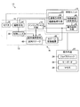
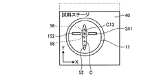
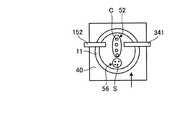
図1は、本発明のマニピュレーションシステムの一例であるインジェクション装置の一実施形態の概略構成を示すブロック図であり、図2は、図1に示すインジェクション装置の概略構成を示す斜視図であり、図3は、図2に示すインジェクション装置の顕微鏡及びインジェクション手段を拡大して示す斜視図である。また、図4−1は、図1に示すインジェクション装置の試料保持部材の概略構成を示す上面図であり、図4−2は、図4−1に示す試料保持部材11に保持される培地及び対象細胞の概略構成を示す断面図である。図1、図2及び図3に示すインジェクション装置10は、試料保持部材11と、画像取得手段12と、インジェクション手段14と、移動手段16と、制御ユニット18と、操作主手段22と、試料保持部材11や移動手段15等を支持する支持体30とを有する。
FIG. 1 is a block diagram showing a schematic configuration of an embodiment of an injection apparatus which is an example of a manipulation system of the present invention, and FIG. 2 is a perspective view showing a schematic configuration of the injection apparatus shown in FIG. 3 is an enlarged perspective view showing a microscope and injection means of the injection apparatus shown in FIG. FIG. 4A is a top view showing a schematic configuration of the sample holding member of the injection apparatus shown in FIG. 1, and FIG. 4-2 shows the culture medium held by the
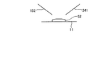
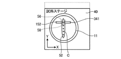
試料保持部材11は、図4−1及び図4−2に示すように、対象細胞C及び培地52を保持する皿状の部材である。試料保持部材11は、培地52の状態を撮影できるように、透明の部材で構成されている。ここで、試料保持部材11としては、シャーレを用いることができる。また、培地(ドロップ)52には、図4−1及び図4−2に示すように、内部に対象細胞Cが分散されている。さらに、図4−2に示すように、試料保持部材11には、パラフィンオイル54が充填されている。これにより、培地52は、試料保持部材11に流動性のある状態で、また、培地52が蒸発しない状態で保持されている。本実施例は、蒸発防止用のパラフィンオイル54が充填されることで流動性がある状態で試料保持部材11に保持された培地52に分散された対象細胞Cにインジェクション操作を行う。なお、本実施例では、対象細胞Cとして卵細胞を用いている。
As shown in FIGS. 4A and 4B, the
また、対象細胞Cは、図4−1に示すように、試料保持部材11上に、培地52を線上に載置し、複数の対象細胞Cを単列上に配置されている。なお、対象細胞Cは、同一直線上に配置することが好ましいが、対象細胞が配列される方向に直交する方向にずれた状態で配置してもよい。つまり、線上に載置した培地52の延在方向、つまり、長手方向に一定以上の間隔で対象細胞Cを配置し、延在方向に直交する方向、つまり、短手方向に複数の対象細胞Cが配置されないようにすればよい。このように、複数の対象細胞を単列上に配置することで、後述するインジェクション手段14による操作中に、インジェクション手段14が操作対象の対象細胞C以外の対象細胞Cと接触することを防止できる。
Further, as shown in FIG. 4A, the target cell C has a
画像取得手段12は、対物レンズ32と、撮影手段34と、モニタ38とを有し、視野内の状態を拡大して観察することができるシステムであり、試料保持部材11に保持された対象細胞C及び培地52の画像を取得する。対物レンズ32は、試料保持部材11の視野内に配置された部分の画像を拡大して取得する光学系である。撮影手段34は、一定の視野を有するカメラであり、対物レンズ32で取得した画像(対象の領域が対物レンズ32により拡大された画像)を撮影し、取得する。また、撮影手段34は、制御手段18によって動作が制御される。例えば、操作者からの入力、予め決められた設定等に応じて、撮影した画像をモニタ38に表示させたり、撮影した画像を記憶させたりする。なお、画像取得手段12を構成する対物レンズ32は、焦点合わせアクチュエータ(図示省略)により電動で焦点合わせを行うことができる機構である。また、対物レンズ32は、試料保持部材11に保持された培地52を観察する際の倍率を複数の倍率の中から選択することができる。なお、インジェクション装置10のうち、対物レンズ32と、試料ステージ40と、移動手段16とを組み合わせることで、試料ステージ40上の視野内の状態を拡大して観察することができる顕微鏡13となる。
The
次に、図3、図5、図6及び図7を用いて、インジェクション手段14について詳細に説明する。ここで、図5は、図3に示すインジェクション装置のインジェクション用電動4軸マニピュレータの概略的構成を示す斜視図である。図6は、図5に示すインジェクション用電動4軸マニピュレータのナット回転型アクチュエータの概略構成を示す斜視図であり、図7は、図6に示すナット回転型アクチュエータの概略構成を示す断面図である。 Next, the injection means 14 will be described in detail with reference to FIG. 3, FIG. 5, FIG. 6, and FIG. Here, FIG. 5 is a perspective view showing a schematic configuration of the electric four-axis manipulator for injection of the injection apparatus shown in FIG. 6 is a perspective view showing a schematic configuration of the nut rotary actuator of the electric four-axis manipulator for injection shown in FIG. 5, and FIG. 7 is a cross-sectional view showing a schematic configuration of the nut rotary actuator shown in FIG. .
インジェクション手段14は、図3に示すように、ホールディング用の電動4軸(XYZ及び直動)マニピュレータ140と、インジェクション用の電動4軸(XYZ及び直動)マニピュレータ160とで構成されている。各電動4軸マニピュレータ140、160は支持体30に取り付けられている。ホールディング用の電動4軸マニュピレータ140は、培地52中の対象細胞Cをホールディングピペット151(後述する)で保持する。また、インジェクション用の電動4軸マニピュレータ160は、先端が先鋭なインジェクションキャピラリ341(後述する)を対象細胞Cに差し込む等の操作を行う。
As shown in FIG. 3, the
また、電動4軸マニピュレータ140、160は、脚149、169により重力方向に支持されている。つまり、脚149は、電動4軸マニピュレータ140を支持し、脚169は、電動4軸マニピュレータ160を支持している。これにより、各電動4軸マニピュレータ140、160は、高い安定性で支持される。なお、本実施形態では、各電動4軸マニピュレータ140,160に対して、それぞれ1箇所にしか脚149,169を配置していないが、複数の脚を配置してもよい。
The electric four-
ホールディング用の電動4軸マニピュレータ140は、3軸(XYZ)方向に組み合わせて構成されている3つの1軸アクチュエータ141、142、143と、ナット回転型アクチュエータ150と、その先端にホールディングキャピラリ152が装着されたホールディングピペット151とで構成される。ホールディングピペット151は、吸引機構と接続されており、ホールディングキャピラリの内部の空洞を陰圧にして、先端の開口に対象細胞Cを吸引させる。なお、1軸アクチュエータ141、142、143と、ナット型アクチュエータ150は、後述するインジェクション用の電動4軸マニュピレータ160の各部と同様の構成であるので、後ほど説明する。
The holding electric four-
インジェクション用の電動4軸マニュピレータ160は、3軸(XYZ)方向に組み合わせて構成されている3つの1軸アクチュエータ161、162、163と、ナット型アクチュエータ170と、先端にインジェクションキャピラリ341が装着されたインジェクションピペット340とで構成される。インジェクションピペット340は、圧力(流量)調整可能なインジェクタと接続されている。
The electric four-
図5のように、1軸アクチュエータ161、162、163は、それぞれ、ステッピングモータとカップリングとBS(ボールねじ)と案内要素とスライダとから構成され、オーバーストロークを防止するために駆動軸方向の両端にリミットスイッチが設置されている。1軸アクチュエータ161、162、163は、制御ユニット18の制御に基づいて、ステッピングモータが駆動されることで、連結している部材を所定方向に移動させる。
具体的には、1軸アクチュエータ161は、支持体30に固定され、かつ1軸アクチュエータ162を支持体30に対して移動可能な状態で支持しており、1軸アクチュエータ162をX軸方向に移動させる。また、1軸アクチュエータ162は、1軸アクチュエータ163を1軸アクチュエータ161に対して移動可能な状態で支持しており、1軸アクチュエータ163をY軸方向に移動させる。さらに、1軸アクチュエータ163は、θステージ164を1軸アクチュエータ162に対して移動可能に支持しており、θステージ164をZ軸方向に移動させる。以上より、1軸アクチュエータ161、162、163を駆動することで、θステージ164を互いに直交する3つの軸方向に移動され、3次元で移動させることができる。
As shown in FIG. 5, each of the single-
Specifically, the
また、各1軸アクチュエータ161、162、163には、各手動ノブ161a、162a、163aが設けられており、各1軸アクチュエータ161、162、163のステッピングモータの励磁が切られた場合でも、各手動ノブ161a、162a、163aを操作することで、各1軸アクチュエータ161、162、163を移動させることができる構成となっている。なお、電動4軸マニピュレータ140も同様に構成されている。
Each single-
θステージ164は、1軸アクチュエータ163に固定されており、ナット回転型アクチュエータ170を支持している。θステージ164は、1軸アクチュエータ163に対してナット回転型アクチュエータ170の設置角度を調整することができる機構である。なお、θステージ164は、手動で角度を調整する機構としても、電動により角度を調整する機構としてもよい。また、θステージ164の設置角度は、インジェクションピペット340に装着されるガラス製のインジェクションキャピラリ341の折れ曲がり角度またはインジェクション角度と一致するよう設定することが好ましい。
The
ナット回転型アクチュエータ170は、電動で圧力調整可能なインジェクションピペット340を設置軸方向に往復運動するようにモータ駆動及び圧電素子駆動する駆動機構である。図6及び図7に示すように、ナット回転型アクチュエータ170は、圧電アクチュエータとしての本体を構成するハウジング480を備えており、ほぼ筒状に形成されたハウジング480内には、インジェクションピペット340を駆動対象として、外周側にねじ部を有するねじ軸520と、ねじ軸520を囲む中空状の回転軸540が挿通されている。ハウジング480はその底部がベース560に固定されており、圧電素子を使用した微動機構(「ナノポジショナー」ともいう)として構成されている。
The
ねじ軸520の先端側には、治具580を介してピペット状のインジェクションピペット340の根元側が連結されており、ねじ軸520の中程には、ねじ軸520外周のねじ部とねじ結合されるねじ要素としてのボールねじナット(BSナット)600が装着され、治具580とねじ軸520との間にはスライダ620が連結されている。スライダ620はベース560とほぼ直交する方向に配置され、切り欠き640を間にしてリニアガイド660に連結されている。リニアガイド660はベース560底部側に配置され、ベアリング680を介して、ねじ軸520の軸方向に沿って移動自在にベース560に連結されている。
The base side of a pipette-
すなわち、リニアガイド660は、ねじ軸520の軸方向の移動に合わせて、ねじ軸520の先端側を支持したスライダ620を、ベース560に沿って往復動させるようになっている。この際、ねじ軸520のうちボールねじナット600よりもインジェクションピペット340側の部位が、スライダ620を介してリニアガイド660でスライド自在に支持されるので、ねじ軸520の直線運動をインジェクションピペット340へ伝達することができる。
That is, the
ボールねじナット600は、回転軸540の軸方向一端側(先端側)の段部540aに固定されているとともに、ねじ軸520外周のねじ部とねじ結合され、ねじ軸520がその軸方向に沿って往復動(直線運動)するのを自在に支持するようになっている。すなわち、ボールねじナット600は、回転軸540の回転運動をねじ軸520の直線運動に変換するための要素として構成されている。
The
回転軸540の軸方向他端側は、中空モータ700内の回転部に連結している。中空モータ700のハウジング740は、その底部側がベース560に弾性体としてのゴムワッシャ760を介してボルト780が固定されている。中空モータ700が駆動されると回転軸540が回転し、回転軸540の回転運動がボールねじナット600を介してねじ軸520に伝達され、ねじ軸520がその軸方向に沿って直線運動するようになっている。
The other axial end of the
一方、回転軸540の段部540aに隣接して、軸受800、820が内輪間座840を間にして収納されている。軸受800、820は、それぞれ内輪800a、820aと、外輪800b、820bと、内輪と外輪間に挿入されたボール800c、820cを備え、各内輪800a、820aが回転軸540の外周面に嵌合され、各外輪800b、820bがハウジング480の内周面に嵌合され、回転軸540を回転自在に支持するようになっている。軸受800、820は、内輪間座840を間にし、回転軸540にロックナット860により固定されている。軸受800は、ハウジング480内の段部540aと円環状のスペーサ900と当接することにより、回転軸540の軸方向への移動が規制されるようになっている。軸受820の外輪820bとハウジング480の蓋880との間に、円環状の圧電素子920と円環状のスペーサ900が圧入されている。
On the other hand, the
また、各軸受800、820、圧電素子920は、スペーサ900の長さを調節し、蓋880を閉めることにより、予圧が付与される。具体的には、スペーサ900の長さを調整し、蓋880を閉めると、その位置に応じた締結力が軸受820と軸受800の外輪820b、800bに、軸方向に沿った押圧力として予圧が付与されるとともに、同時に圧電素子920にも予圧が付与される。これにより、軸受800、820および圧電素子920に所定の予圧が付与され、軸受800、820の外輪間に軸方向間の距離としての間隙940が形成される。
The
圧電素子920は、リード線(図示せず)を介してコントローラとしての制御ユニット18に接続されており、制御ユニット18からの電圧に応じて回転軸540の長手方向(軸方向)に沿って伸縮する圧電アクチュエータの一要素として構成されている。すなわち、圧電素子920は、制御ユニット18からの印加電圧に応答して、回転軸540の軸方向に沿って伸縮し、回転軸540をその軸方向に沿って微動させるようになっている。回転軸540が軸方向に沿って微動すると、この微動がねじ軸520を介してインジェクションピペット340に伝達され、インジェクションピペット340の位置が微調整されることになる。
The
上述のように、ナット回転型アクチュエータ170は、中空モータ700によりボールねじナット600の回転運動をねじ軸520の直線運動に変換し、ねじ軸520を直動するが、ねじ軸520に取り付けられたインジェクションピペット340は、中空モータ700の駆動時にリニアガイド660により回転せず、回り止めの機能を有している。このため、中空モータ700の駆動によりインジェクションピペット340が直線往復運動できる。
As described above, the
図6及び図7に示すナット回転型アクチュエータ170は、中空モータ700を駆動することで、インジェクションピペット340を駆動し顕微鏡視野中央部ヘセットし、また、顕微鏡視野中央部から退避する機能を有し、圧電素子920を駆動することで、インジェクションピペット340の先端に取り付けたインジェクションキャピラリ341による細胞(卵)に対する穿孔動作をアシストすることができる。なお、同様に、ナット回転型アクチュエータ150も、ホールディングピペット151の先端に取り付けたホールディングキャピラリ152の吸引、支持動作をアシストする。また、各ピペットには、さらに、各ガラスキャピラリの内部の圧力を調整するインジェクタが設けられている。
The
移動手段16は、試料台(試料ステージ)40と、ステージ移動機構42とを有し、試料保持部材11を水平方向に移動させる。なお、移動手段16は、電動で試料保持部材11を移動させる手段である。
The moving means 16 includes a sample stage (sample stage) 40 and a
試料ステージ40は、中心部近傍には開口が形成されている。
The
ステージ移動機構42は試料ステージ40を水平方向に移動させるXYステージである。ステージ移動機構42は、試料ステージ40を支持し、試料ステージ40を水平方向において所定の1方向(以下「Y軸方向」とする。)に移動させるY軸移動機構と、Y軸移動機構を介して試料ステージ40を支持し、試料ステージ40及びY軸移動機構を水平方向においてY軸方向に直交する方向(以下「X軸方向」とする)に移動させるX軸移動機構とで構成されている。なお、移動機構としては、ステージに固定されたナット、ナットと螺合したボールねじ、ボールねじを回転させる回転モータ、ステージの移動方向に延びて配置されたレール上の部材でありステージを案内する案内部材とを有し、回転モータによりボールねじを回転させてナット及びステージを案内部材に沿って移動させる機構を用いることができる。また、移動機構としては、この他、種々の移動機構を用いることができ、例えば、超音波リニアモータを用いる移動機構、静電アクチュエータを用いる移動機構等も用いることができる。
The
制御ユニット18は、画像処理手段44と、移動経路設定手段46と、動作制御手段48とを有し、CPU、メモリ等で構成された処理装置である。制御ユニット18としては、パソコン(パーソナルコンピュータ)として使用されている処理装置(演算装置)を用いることができる。つまり、パソコンが制御ユニット18の機能をソフトウェアの1つとして有する構成とし、パソコンにより制御ユニット18の処理を行うようにしてもよい。制御ユニット18は、操作手段22から入力された情報や、各部から送られる情報に基づいて、インジェクション装置10の各部を制御する。画像処理手段44は、画像合成部50を有し、撮影手段34により撮影した画像から、対象細胞Cの試料ステージ40上における位置および各対象細胞Cの大きさ、形状、重心等を検出する。画像合成部50は、撮影手段34により撮影された培地52の各位置の画像を合成し、培地52の全体が撮影された1枚の画像を作成する。
The
移動経路設定手段46は、画像処理手段44で検出した各対象細胞Cの位置と大きさとに基づいて、各対象細胞の穿孔を形成する部分、つまり、試料ステージ40に支持された試料保持部材11上の座標を特定し、穿孔を形成する対象細胞をインジェクション手段14の作業領域(つまり、ホールディング用の電動4軸マニピュレータ140で保持することができる領域)に移動させるための移動量と移動経路を算出する。ここで、移動経路設定手段46は、対象細胞の穿孔を形成する部分と、他の対象細胞の穿孔を形成する部分とを結んで経路を設定する。
The movement path setting means 46 is based on the position and size of each target cell C detected by the image processing means 44, that is, the part that forms a perforation of each target cell, that is, the
動作制御手段48は、画像取得手段12による画像の取得動作や、インジェクション手段14による細胞への穿孔動作や、移動手段16による試料保持部材11の移動動作を制御する。具体的には、動作制御手段48は、移動手段16により試料保持部材11を所定量移動させて、所定量移動させる毎に画像取得手段12により試料保持部材11の画像を取得する。このように、試料保持部材11を一定量移動させつつ画像を撮影させることで、試料保持部材11の培地52全体の画像を取得することができる。また、動作制御手段48は、移動経路設定手段46により設定された移動経路に従って、試料保持部材11を移動させ、対象細胞を作業領域に移動させたら、インジェクション手段14により対象細胞を操作する。本実施例は、対象細胞Cに穿孔を形成し、DNAを注入する。
The operation control unit 48 controls an image acquisition operation by the
次に、操作手段22は、操作者が操作して指示を入力する手段であり、2本のジョイスティック24と、キーボード26と、マウス28とで構成される。操作手段22は、操作者により行われた操作に対応する信号を操作信号として制御ユニット18に送る。ジョイスティック24は、ハンドルと複数のボタンとで構成されている。また、一方のジョイスティック24は、ホールディング用の電動4軸マニュピレータ140の操作に用いられ、他方のジョイスティック24は、インジェクション用の電動4軸マニピュレータ160の操作に用いられる。つまり、2本のジョイスティック24は、操作者によって操作されることで、それぞれの4軸マニピュレータを駆動させる駆動信号を制御ユニット18に送る。また、キーボード26及びマウス28は、条件の入力や、モニタ48に表示する画面の操作等に用いられる。インジェクション装置10は、基本的に以上のような構成である。
Next, the operating
(実施例1)
(マニピュレータシステムの動作に関する説明)
次に、図8−1から図14−8を用いて、インジェクション装置10により卵細胞にDNAを注入する操作について説明する。ここで、図8−1は、インジェクション手段と試料台との関係を説明するための説明図であり、図8−2は、図8−1に示すインジェクション手段と試料台とをX−Z平面で切断した断面図である。また、図8−3は、インジェクション手段と試料台との関係を説明するための説明図であり、図8−4は、図8−3に示すインジェクション手段と試料台とをX−Z平面で切断した断面図である。また、図9−1は、インジェクション手段と試料台との関係を説明するための説明図であり、図9−2は、図9−1に示すインジェクション手段と試料台とをX−Z平面で切断した断面図である。また、図10−1から図10−4は、それぞれインジェクション手段の動作を説明するための説明図である。
Example 1
(Explanation regarding the operation of the manipulator system)
Next, an operation for injecting DNA into an egg cell by the
まず、インジェクション手段14は、ナット回転型アクチュエータ150によりホールディングキャピラリ152を移動させ、ナット回転式アクチュエータ170によりインジェクションキャピラリ341を移動させることで、ホールディングキャピラリ152の先端及びインジェクションキャピラリ341の先端を、図8−1及び図8−2に示すような試料ステージ40に近接した位置から、図8−3及び図8−4に示すような試料ステージ40と一定距離離れた位置まで移動させることができる。なお、インジェクション手段14は、対象細胞Cに穿孔を形成する穿孔形成動作を行う前には、図8−1及び図8−2に示すように、1軸アクチュエータ141、142、143、161、162、163や、ナット回転型アクチュエータ150、170を駆動させ、ホールディングキャピラリ152の先端及びインジェクションキャピラリ341の先端を試料ステージ40に近接させて、基準位置の設定を行うようにすることが好ましい。つまり、原点の設定をすることが好ましい。このように基準位置を設定、もしくは再設定することで、ホールディングキャピラリ152とインジェクションキャピラリ341とを所望の位置により正確に移動させることができる。また、基準位置の設定を行うタイミングは特に限定されず、穿孔動作を行う度に設定しても、装置起動時に1回のみ行うようにしてもよい。
First, the injection means 14 moves the holding
インジェクション手段14の基準位置(原点)の設定が終了したら、図9−1及び図9−2に示すように、試料保持部材11を試料ステージ40に設置する。なお、このとき、試料保持部材11は、培地52の長手方向が、Y軸方向と平行になるように、具体的には、ホールディングキャピラリ152及びインジェクションキャピラリ341の延在方向に対して直交するように設置する。また、試料保持部材11を試料ステージ40に載置する場合は、図9−2に示すように、ホールディングキャピラリ152の先端及びインジェクションキャピラリ341の先端が、試料ステージ40から離れた状態にしておく。これにより、試料保持部材11を載置しやすくすることができ、かつ、ホールディングキャピラリ152及びインジェクションキャピラリ341が、培地52や試料保持部材11と接触することを防止することができる。
When the setting of the reference position (origin) of the injection means 14 is completed, the
インジェクション装置10は、培地52が載置された試料保持部材11が試料ステージ40に設置されたら、ナット回転型アクチュエータ150、170を駆動させて、図8−1及び図8−2に示すように、ホールディングキャピラリ152及びインジェクションキャピラリ341を試料ステージ40に近接させる。このとき、ホールディングキャピラリ152が近接した領域(処理領域)には、培地52の対象細胞Cがある。なお、処理領域に対象細胞Cを移動させる方法については後ほど説明する。
As shown in FIGS. 8A and 8B, the
(1つの細胞に対するインジェクション操作に関する説明)
このように、処理領域に対象細胞Cがある状態で、ホールディング用の電動4軸マニピュレータ140のホールディングピペット151を駆動し、ホールディングキャピラリ152を陰圧にすると、処理領域の対象細胞Cは、ホールディングキャピラリ152に吸引され、図10−1に示すように、対象細胞Cがホールディングキャピラリ152の先端に保持された状態となる。
(Explanation on injection operation for one cell)
As described above, when the holding
次に、インジェクション手段14を駆動してインジェクションキャピラリ341を対象細胞C側に移動させ、図10−2に示すように、インジェクションキャピラリ341の先端を対象細胞Cに当接させる。
Next, the injection means 14 is driven to move the
その後、さらに、圧電素子920を駆動してインジェクションキャピラリ341を対象細胞C側(つまり、図10−3中矢印A方向)に移動させることで、図10−3に示すように、インジェクションキャピラリ341の先端が対象細胞Cの内部に挿入され、対象細胞Cに穿孔が形成される。その後、インジェクション手段14は、インジェクションキャピラリ341の先端から対象細胞CにDNAを注入する。なお、本実施形態では、DNAを注入したが、使用目的によって種々の物を注入することができる。なお、対象細胞Cに注入するDNAは、インジェクション動作を行う前に、吸引する等によりインジェクションキャピラリ341の内部に保持されており、インジェクション手段14のインジェクションキャピラリ341は、内部に保持してあるDNAを対象細胞Cの内部に注入する。
Thereafter, by further driving the
図10−3に示すインジェクション動作を行い対象細胞Cに穿孔を形成し、DNAを注入したら、インジェクションキャピラリ341を対象細胞Cから離れる方向(つまり、図10−4中矢印B方向)に移動させ、図10−4に示すように、対象細胞Cからインジェクションキャピラリ341を抜く。その後、ホールディングキャピラリ152による吸引を停止することで、対象細胞Cはホールディングキャピラリ152から開放され、試料ステージ40の移動に応じて、移動する状態となる。このように、図10−1から図10−4に示すようにインジェクション手段14を駆動させることで、対象細胞Cを操作することができる。
When the injection operation shown in FIG. 10-3 is performed to form a perforation in the target cell C and DNA is injected, the
(画像処理、移動経路設定に関する説明)
次に、図11、図12−1及び図12−2を用いて、培地の画像を取得し、培地中に含まれる複数の対象細胞を検出し、対象細胞を順次処理領域に移動させる経路設定方法について説明する。ここで、図11は、培地全体の画像の取得方法及び移動経路設定方法の一例を示すフロー図である。また、図12−1は、インジェクション装置の動作を説明するための説明図であり、図12−2は、インジェクション装置の動作を説明するための説明図である。
(Explanation regarding image processing and movement route setting)
Next, using FIG. 11, FIG. 12-1, and FIG. 12-2, route setting is performed to acquire an image of the medium, detect a plurality of target cells included in the medium, and sequentially move the target cells to the processing region A method will be described. Here, FIG. 11 is a flowchart illustrating an example of an image acquisition method and a movement route setting method for the entire medium. Moreover, FIG. 12-1 is explanatory drawing for demonstrating operation | movement of an injection apparatus, and FIG. 12-2 is explanatory drawing for demonstrating operation | movement of an injection apparatus.
まず、準備として、試料保持部材11に、対象細胞Cを含有する培地52を形成し、試料保持部材11上に培地52が載置された状態とする。さらに、試料保持部材11にパラフィンオイル54を充填し、培地52の外周をパラフィンオイル54が覆っている状態とする。その後、試料保持部材11を試料ステージ40の所定位置に設置する。
First, as a preparation, the medium 52 containing the target cell C is formed on the
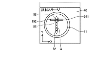
インジェクション装置10は、培地52が載置された試料保持部材11が試料ステージ40に設置されたら、ステップS12として、培地52の中心位置を検出し、画像取得手段12の視野の中心と培地52の中心とが重なるように試料保持部材11を移動させる。具体的には、画像取得手段12により試料保持部材11の画像を撮影し、撮影した画像から培地52の中心を検出し、検出した中心位置が、視野56の中心と重なるように、移動手段16により試料保持部材11の位置を移動させる。なお、この画像取得手段12の視野の中心と培地52の中心とが重なるように試料保持部材11を移動させる動作は、操作者がモニタ38の画像を確認しつつ、手動で行うようにしてもよい。また、インジェクション装置10は、処理スタートの指示が操作者から入力されること(例えば、画像集録ボタンが押される等)を検出したら処理(ステップS12)を開始するようにしても、試料ステージ40に試料保持部材11が設置されたか否かを検出するセンサを設け、このセンサにより試料保持部材11が設置されたことを検出したら処理を開示するようにしてもよい。
When the
次に、動作制御手段48は、ステップS14として、培地52全体(撮影対象領域の全域)の画像を取得する。ここで、ステップS14の画像は、培地52内の対象細胞Cの細胞の輪郭と、対象細胞の内部とを画像上認識することができる倍率で撮影する。このとき、視野56が培地52の全体よりも小さい場合は、培地52を複数の領域に分割して、分割した領域が視野56に入るように試料保持部材11を移動させて、視野に入った領域の画像を取得することを、順次全ての領域で行い、各領域の画像を取得する。具体的には、図12−1に示すように、領域毎に分割して画像を取得する。その後、各領域の画像を画像合成部50で合成し、対象細胞Cが認識できる状態の倍率で撮影された培地52全体の一枚の画像を作成する。
Next, the operation control means 48 acquires the image of the whole culture medium 52 (all the imaging | photography object area | regions) as step S14. Here, the image of step S <b> 14 is taken at a magnification at which the outline of the target cell C in the
次に、画像処理手段44は、ステップS16として、ステップS14で作成した画像から、対象細胞Cを検出する。ここで、対象細胞Cは、作成した画像に対し画像処理を行うことで検出することができる。例えば、画像を2値化し、閾値の設定により、培地の溶媒と対象細胞Cとを分離し、対象細胞Cを検出する。このとき、対象物質Cとして検出する大きさや形状の基準を設定しておくことで、培地中に混入している対象細胞C以外の物質は、対象細胞Cとして検出しないようにすることができる。 Next, the image processing means 44 detects the target cell C from the image created at step S14 as step S16. Here, the target cell C can be detected by performing image processing on the created image. For example, the image is binarized, the medium solvent is separated from the target cell C by setting a threshold, and the target cell C is detected. At this time, by setting a standard for the size and shape to be detected as the target substance C, substances other than the target cell C mixed in the medium can be prevented from being detected as the target cell C.
次に、画像処理手段44は、ステップS18として、検出した各対象細胞Cの画像上つまり試料保持部材11上での位置(座標)と、各対象細胞Cの大きさを検出する。ここで、各対象細胞Cの座標は、座標上の一点、例えば、画像の中心を基準とし、ステージ移動機構42のX軸移動機構により移動される方向をX軸とし、Y軸移動機構により移動される方向をY軸とした座標軸を用いて設定する。この座標軸を用いて、画像上の各対象細胞Cの位置を検出することで、画像上に確認される対象細胞の位置を検出する。具体的には、図12−2に示すように、対象細胞C1の位置は、座標(x1、y1)と検出され、対象細胞C2の位置は、座標(x2、y2)と検出され、以下同様に対象細胞C9までの位置が検出される。また、対象細胞Cの大きさは、画像処理によって特定された各対象細胞の外形線から算出することができる。また、画像処理手段44は、対象細胞Cの大きさとともに形状、重心等も検出する。
Next, in step S18, the image processing unit 44 detects the position (coordinates) on the detected image of each target cell C, that is, the
次に、移動経路設定手段46は、ステップS20として、ステップS18で検出した対象細胞Cの位置、大きさに基づいて、移動手段16により試料保持部材11を移動させる経路を設定する。ここで、移動経路設定手段46は、対象細胞C1、対象細胞C2、対象細胞C3と、対象細胞C1から対象細胞C11まで番号の小さい対象細胞から順番に対象細胞が、インジェクション手段14の処理領域58と重なるように(つまり、ホールディングキャピラリ152で吸引、保持が可能な位置に)、試料保持部材11を移動させる経路を設定する。なお、対象細胞Cに形成する穿孔は、対象細胞Cの端部に形成する。なお、移動経路設定手段46は、検出した対象細胞Cの位置、大きさに基づいて、対象細胞Cがインジェクション手段14の処理領域58と重なるように、試料保持部材11を移動させる経路を設定する。
Next, as step S20, the movement path setting means 46 sets a path for moving the
なお、本実施形態では、培地52の図12−2中上側の端部、つまり、Y軸座標値が最も位置にある対象細胞C1に最初に穿孔を形成し、その対象細胞C1よりも、培地52の図12−2中下側にあり、かつ最も近い対象細胞C2の順に操作を行うように経路を設定する。具体的には、移動経路設定手段46は、設定時の焦点位置と対象細胞C1の穿孔形成予定位置との距離を算出し、算出結果から、X軸方向の移動距離X1、Y軸方向の移動距離Y1を移動経路として設定する。次に、対象細胞C1の穿孔形成予定位置と対象細胞C2の穿孔形成予定位置との距離を算出し、算出結果から、X軸方向の移動距離X2、Y軸方向の移動距離Y2を移動経路として設定する。次に、対象細胞C2の穿孔形成予定位置と対象細胞C3の穿孔形成予定位置との距離を算出し、算出結果から、X軸方向の移動距離X3、Y軸方向の移動距離Y3を移動経路として設定する。以下、同様にして、順次、培地52の図12−2中下側にある対象細胞に操作を行うように、対象細胞の穿孔形成予定位置から他の対象細胞の穿孔形成予定位置までの距離を算出し、算出した距離分を移動経路と設定することで、各対象細胞の穿孔形成予定位置が順次処理領域58と重なるように、試料保持部材11の移動経路を設定することができる。
In this embodiment, a perforation is first formed in the upper end of the
(本発明のマニピュレーションシステム駆動方法の全体の流れに関する説明)
次に、図13、図14−1から図14−8を用いて、インジェクション装置のインジェクション動作について説明する。ここで、図13は、インジェクション装置の動作を説明するフロー図であり、図14−1から図14−8は、それぞれインジェクション装置の他の動作を説明するための説明図である。
(Explanation regarding the overall flow of the manipulation system driving method of the present invention)
Next, the injection operation of the injection apparatus will be described with reference to FIGS. 13 and 14-1 to 14-8. Here, FIG. 13 is a flowchart for explaining the operation of the injection apparatus, and FIGS. 14-1 to 14-8 are explanatory views for explaining other operations of the injection apparatus.
まず、ステップS40として、インジェクション手段の装着と、原点位置の設定を行う。具体的には、インジェクション手段14をインジェクション装置10の所定位置に装着し、図8−1から図8−4で説明したように、インジェクション手段14の電動4軸マニピュレータ140、160を駆動させて、原点位置を設定する。なお、原点位置は、試料ステージ40上に試料保持部材11を配置しても、ホールディングキャピラリ152及びインジェクションキャピラリ341の両方の先端が、試料保持部材11に近接しているが接触せず、かつ、処理領域(撮影手段34に撮影される領域、つまり顕微鏡13で観察可能な視野)の近傍に配置される位置である。また、インジェクション手段14の装着は、操作者により行われるが、既に装着されている場合は、省略される。
First, as step S40, the injection means is mounted and the origin position is set. Specifically, the
インジェクション装置10は、ステップS40で原点位置の設定が完了したら、ステップS42として、ホールディングキャピラリ152とインジェクションキャピラリ341を退避させる。つまり、ホールディングキャピラリ152とインジェクションキャピラリ341とを原点位置から離れた状態に移動させる。
When the setting of the origin position is completed in step S40, the
インジェクション装置10は、ステップS42でキャピラリを退避させたら、ステップS44として、試料保持部材11の搭載と初期位置の設定を行う。ここで、初期位置とは、試料ステージ40における試料保持部材11の位置である。また、上述のステップS12の前の準備で説明したように、試料保持部材11は、操作者により試料ステージ40に搭載(載置)される。さらに、初期位置の設定は、操作者の操作により入力され、決定された位置を初期位置としても、制御ユニット18の制御により設定された位置を初期位置としてもよい。
When the capillary is retracted in step S42, the
インジェクション装置10は、ステップS44で初期位置が設定されたら、ステップS46として、培地52及び対象細胞Cの画像を撮影し、撮影した画像を合成し、搬送経路の設定を行う。具体的には、上述した、図11のステップS12からステップS20の動作を行い、搬送経路を設定する。
When the initial position is set in step S44, the
次に、インジェクション装置10は、ステップS46で移動経路を算出、設定したら、動作制御手段48は、ステップS48として、設定した移動経路に従って、移動手段16により試料保持部材11を移動させる。具体的には、試料保持部材11を保持する試料ステージ40を、移動手段16のステージ移動機構42によりX軸方向、Y軸方向に移動させ、対象細胞C1を処理領域58まで移動させる。なお、移動経路には、対象細胞の位置も設定されており、動作制御手段48は、移動経路上の対象細胞の位置が処理領域58に重なる位置まで移動させたら、移動を停止させる。
Next, when the
インジェクション装置10は、ステップS48で対象細胞Cを処理領域58まで移動させたら完了したら、ステップS50として、動作制御手段48の制御に基づいて、インジェクション手段14により対象細胞Cにインジェクション操作を行う。つまり、対象細胞Cに穿孔を形成し、DNAを注入する。なお、対象細胞Cには、上述した図10−1から図10−4に示す方法で操作を行う(施す)ことができる。
When the
インジェクション装置10は、ステップS50で対象細胞にインジェクション操作を行ったステップS52として、キャピラリを退避させる。つまり、ホールディングキャピラリ152とインジェクションキャピラリ341とを退避させ、試料保持部材11を移動させても、各キャピラリと試料保持部材11とが接触しない状態にする。
The
インジェクション装置10は、ステップS52でキャピラリを退避させたら、ステップS54として、検出した対象細胞の全てにインジェクション操作を行ったかを判定する。動作制御手段48は、ステップS54で、操作していない対象細胞があると(つまり、No)判定したら、ステップS58として、設定した移動経路に従って、移動手段16により試料保持部材11を移動させる。これにより、試料保持部材11に保持された培地52が移動され、次にインジェクション操作を行う対象細胞が処理領域58に移動させる。動作制御手段48は、ステップS58で試料保持部材11を移動させたら、ステップS50に進み、インジェクション操作を行う。このように、動作制御手段48は、培地52の対象細胞Cの全てに操作を行うまで、ステップS58、ステップS50、ステップS52、ステップS54の動作を繰り返す。
When the capillary is retracted in step S52, the
具体的には、インジェクション装置10は、移動経路を設定したら、設定した移動経路に基づいてステージ移動機構42を移動させ、図14−1に示すように、対象細胞C1を処理領域58に搬送する。なお、処理領域58は、撮影手段34により撮影される視野56内にある。また、図14−1から図14−8では、細胞穿孔手段の各部、培地52及び対象細胞Cを模式的に示しており、培地52に含まれ対象細胞Cの一部の図示を省略する。
Specifically, after setting the movement route, the
インジェクション装置10は、対象細胞C1を処理領域に移動させたら、図14−2に示すように、ホールディングキャピラリ152の先端を対象細胞C1の近傍に移動させる。インジェクション装置10は、ホールディングキャピラリ152の先端を対象細胞C1の近傍に移動させたら、ホールディングピペット151を駆動させ、対象細胞C1を吸引し、図14−3に示すように、ホールディングキャピラリ152の先端を対象細胞C1に吸着させる。なお、対象細胞C1を処理領域に移動させた際に、培地52内で微小な相対位置のずれが発生しても、ホールディングキャピラリ152で吸引することで、対象細胞Cを移動させ、先端に吸着させることができる。
When the target cell C1 is moved to the processing region, the
インジェクション装置10は、ホールディングキャピラリ152により、対象細胞C12を保持したら、図14−4に示すように、インジェクションキャピラリ341を移動させ、対象細胞C12に操作を行う。インジェクション装置10は、対象細胞C1に操作を行ったら、インジェクションキャピラリ341を対象細胞C12から抜き取り、ホールディングピペット152の駆動を停止した後、図14−5に示すように、インジェクションキャピラリ341とホールディングキャピラリ151とを、対象細胞C1と一定距離離れた位置に移動させる。
After holding the target cell C12 by the holding
インジェクション装置10は、その後、図14−6に示すように、対象細胞C2が処理領域58内に入るようにステージ移動機構42により試料ステージ40を移動させる。その後、図14−2から図14−5に示す手順と同様の順序で、対象細胞C2に操作を行う。
Thereafter, the
インジェクション装置10は、その後、図14−7に示すように、対象細胞C3が処理領域58内に入るようにステージ移動機構42により試料ステージ40を移動させる。その後、図14−2から図14−5に示す手順と同様の順序で、対象細胞C14に穿孔を形成し、DNAを注入する。さらに、インジェクション装置10は、その後、図14−8に示すように、対象細胞C4が処理領域58内に入るようにステージ移動機構42により試料ステージ40を移動させる。その後、図14−2から図14−5に示す手順と同様の順序で、対象細胞C5に穿孔を形成し、DNAを注入する。細胞対象装置10は、培地52内の対象細胞Cの全てに穿孔を形成し、DNA注入するまで、上記工程を繰り返す。
Then, the
動作制御手段48は、全ての対象細胞に操作を行ったら、ステップS54で、対象細胞の全てに操作を行った(つまり、Yes)と判定し、処理を終了する。 When the operation control unit 48 has operated all the target cells, in step S54, the operation control unit 48 determines that all the target cells have been operated (that is, Yes), and ends the processing.
インジェクション装置10は、以上のようにして、培地52に分散された対象細胞Cに操作を行う。このように、インジェクション装置10は、ホールディングキャピラリ152で対象細胞を保持してから、インジェクションキャピラリ341で操作することで、試料保持部材11内で対象細胞Cが移動しやすい場合でも、適切に操作を行うことができる。つまり、インジェクション装置10は、培地52が液状の物質で対象細胞Cが培地52を移動する構成であっても好適に対象細胞Cに穿孔を形成することができる。言い換えれば、インジェクション装置10は、液状の物質に対象細胞Cを含有させた状態であっても対象細胞に適切に操作を行うことができる。
The
また、本実施例のように、対象細胞を単列上に配置することで、上述したように、操作中に、他の対象細胞がインジェクション手段に接触することを防止でき、かつ、試料ステージ40の移動量を少なくすることができ、より効率よく対象細胞に操作を行うことができる。
Further, as described above, by arranging the target cells on a single row as in the present embodiment, it is possible to prevent other target cells from coming into contact with the injection means during the operation as described above, and the
また、インジェクション装置10は、複数の画像を合成し、培地全体、つまり撮影対象領域全体を示す1枚の画像を作成することで、全領域のどの位置に対象細胞が載置されているかを把握することができ、対象細胞を探しやすくすることができる。
In addition, the
また、インジェクション装置10は、培地52上の対象細胞の位置を検出し、検出結果から試料保持部材11の移動経路を設定することで、操作者が移動手段16により試料保持部材11を移動させつつ、培地52内の対象細胞Cを探す必要がなくなる。これにより、熟練度の低い操作者が操作した場合でも、短時間で対象細胞に操作を行うことができ、作業効率を高くすることができる。
The
また、画像処理手段44により画像上の対象細胞Cを検出することで、対象細胞Cの検出もれを抑制でき、対象細胞Cを無駄なく使用することができる。また、操作者の操作で対象細胞Cを検出する場合は、既に操作を行った細胞を再び発見し、操作が行われているか否かを判定したりする必要がある。これに対して、インジェクション装置10は、画像処理手段44により対象細胞Cを検出し、かつ、移動経路設定手段46により、設定した経路で、一つずつの対象細胞Cを処理領域58まで移動させるようにするため、対象細胞Cに操作が行われているか否かを判定する必要がなくなる。このため、作業効率を高くすることができる。また、各対象細胞Cを1度ずつ処理領域58に移動させるようにできるため、1つの対象細胞Cに2回操作を行ってしまうことも抑制することができる。
Further, by detecting the target cell C on the image by the image processing means 44, the detection leak of the target cell C can be suppressed, and the target cell C can be used without waste. In addition, when the target cell C is detected by an operator's operation, it is necessary to find again a cell that has already been operated and determine whether or not the operation has been performed. On the other hand, the
ここで、本実施形態では、ステップS14で、培地の画像を複数の領域に分割して取得した後、各領域の画像を合成することで、培地全体を示す1枚の画像を作成したが本発明はこれに限定されない。対象細胞Cが認識できる状態の倍率でも培地全体が視野内に収まる場合は、培地全体を分割せずに、1度の撮影で取得した1枚の画像を用いればよい。また、本実施形態では、培地全体を9分割したが、分割数は特に限定されず、2分割でも、4分割でも、16分割でもよい。 Here, in the present embodiment, in step S14, the image of the culture medium is obtained by dividing it into a plurality of areas, and then, by synthesizing the images of the respective areas, one image showing the entire culture medium is created. The invention is not limited to this. If the entire medium can be accommodated within the field of view even at a magnification that allows the target cell C to be recognized, it is sufficient to use a single image acquired by one image capture without dividing the entire medium. In the present embodiment, the whole medium is divided into nine parts, but the number of divisions is not particularly limited, and may be two parts, four parts, or 16 parts.
また、ステップS24の焦点合わせは、本実施形態のように、電動かつ自動で焦点合わせを行うようにすることが好ましいが、操作者がアクチュエータを操作し焦点合わせを行うようにしてもよい。この場合は、動作制御手段48は、操作者により焦点合わせが完了したという指示の入力を確認したら、ステップS26に進むようにすればよい。なお、操作者による指示は、キーボードや専用のスイッチ等の入力手段を設け、これらの手段から入力するようにすればよい。また、焦点合わせは、基本的に自動で行うようにし、操作者により焦点が合っているかを確認するようにしてもよい。この場合は、操作者の確認完了の入力後、次のステップに進むようにすればよい。また、この場合は、焦点がずれている場合は操作者により微調整できるようにすることで、より的確に焦点を合わせることができる。 The focusing in step S24 is preferably performed electrically and automatically as in the present embodiment, but the operator may operate the actuator to perform focusing. In this case, the operation control means 48 may proceed to step S26 after confirming the input of the instruction that the focusing is completed by the operator. Note that an instruction from the operator may be input by providing input means such as a keyboard or a dedicated switch. In addition, focusing may be basically performed automatically, and the operator may confirm whether the focus is in focus. In this case, after the operator's confirmation completion is input, the process may proceed to the next step. In this case, the focus can be adjusted more accurately by allowing the operator to finely adjust the focus when the focus is off.
また、動作制御手段48は、ステップS24にて焦点合わせが完了したら、ステップS26においてそのままの位置でインジェクション手段14による操作(保持、穿孔形成、注入動作)を開始するようにしてもよいが、動作開始前に、試料保持部材11の位置を再調整するようにしてもよい。ここで、再調整の方法としては、操作者がモニタ38で画像を確認しながら、ステージ移動機構42をコントローラ等で操作する方法がある。なお、操作者により再調整を行う場合は、動作制御手段48は、再調整の有無の指示、再調整の終了の指示等が入力されたことを検出したら次のステップに進むようにすればよい。また、再調整の方法としては、画像取得手段12により視野56内の画像を取得し、対象細胞Cの位置を検出し、対象細胞Cの所望位置(本実施形態では、端部)が処理領域58と重なっているかを検出し、所望位置と処理領域58とが離れている場合は、離れている距離分、移動手段16で移動させるようにする。このように、試料保持部材11の位置を再調整することで、対象細胞Cを適切に保持したり、対象細胞Cの所望位置に適切に穿孔を形成したり、対象細胞CにDNAを注入したりすることができる。また、対象細胞Cを適切に操作できることで、対象細胞Cが使用不可能になることを抑制することができる。
Further, when the focusing is completed in step S24, the operation control unit 48 may start the operation (holding, perforation formation, injection operation) by the
なお、インジェクション装置10は、ステップS50で操作者によりインジェクション操作の開始指示の信号が入力されてから、対象細胞の操作(保持、穿孔形成、注入動作)を開始するようにしてもよい。ここで、開始指示の信号を入力する手段は、ジョイスティク、キーボード、フットスイッチ、ボタン等どのような手段でもよい。
Note that the
また、上記実施形態では、ステップS54において、対象細胞の全てに操作を行ったかを、検出した検出結果に基づいて動作制御手段48が自動的に判定するようにしたが、本発明はこれに限定されない。例えば、操作者からの入力される操作を繰り返すか終了するかの指示を検出し、その指示に基づいて動作するようにしてもよい。 In the above embodiment, in step S54, the operation control means 48 automatically determines whether or not all target cells have been operated based on the detected detection result. However, the present invention is not limited to this. Not. For example, an instruction to repeat or end an operation input by the operator may be detected, and the operation may be performed based on the instruction.
また、上記実施形態では、作業効率を高くすることができるという効果をより顕著に得ることができるため、移動経路を設定して自動的に次の対象細胞まで移動させるようにしたが、これに限定されず、操作者の操作により試料台を移動させるようにしてもよい。本実施形態によれば、合成された画像から各対象細胞の相対位置、即ち対象細胞に順次インジェクション操作を行うための試料台の移動量を正確に把握することができるため、視野中に対象細胞が一つの場合でも作業者がモニタで観察しつつ、対象細胞を探す必要がなくなり、作業効率を高くすることができる。また、作業者の熟練度によらず、適切に対象細胞に穿孔を形成することができる。 Further, in the above embodiment, since the effect that the working efficiency can be increased can be obtained more remarkably, the movement route is set and automatically moved to the next target cell. Without limitation, the sample stage may be moved by the operation of the operator. According to the present embodiment, the relative position of each target cell, that is, the amount of movement of the sample stage for sequentially performing the injection operation on the target cell can be accurately grasped from the synthesized image. Even when there is only one, it is not necessary for the operator to look for the target cell while observing on the monitor, and the working efficiency can be increased. In addition, perforations can be appropriately formed in the target cells regardless of the skill level of the operator.
また、上記実施形態では、圧電素子によってインジェクションキャピラリを直動方向に微細に移動させて穿孔を形成したが、本発明はこれに限定されず、1軸アクチュエータによりインジェクションキャピラリを直動方向に移動させて穿孔を形成するようにしてもよい。 In the above embodiment, the injection capillary is finely moved in the linear motion direction by the piezoelectric element to form the perforation. However, the present invention is not limited to this, and the single capillary actuator moves the injection capillary in the linear motion direction. A perforation may be formed.
また、動作制御手段48は、移動手段16のステージ移動機構42による試料保持部材11の移動の制御を、開ループ制御で行っても、閉ループ制御(フィードバック制御)によって行ってもよい。また、開ループ制御を行う場合は、移動時の画像情報を収集し、その情報をフィードバック情報として、位置の調整操作を行ってもよい。
Further, the operation control means 48 may control the movement of the
(実施例2)
次に、本発明のインジェクション装置及びインジェクション装置駆動方法の他の実施例について説明する。具体的には、図15、図16−1から図16−9及び図17−1から図17−7を用いて、インジェクション装置10により卵細胞に精子を注入する操作について説明する。ここで、図15は、試料保持部材の他の一例の概略構成を示す上面図である。また、図16−1から図16−9は、それぞれ、インジェクション装置の他の動作を説明するための説明図である。また、図17−1は、図16−1から図16−3に示すインジェクション装置の断面図である。なお、図16−1から図16−3に示すインジェクション装置は、試料保持部材11が図17−1の断面に直交する方向に移動されるため、試料保持部材11を断面として切断する位置変化するが、断面図の状態が実質的に変化しないので、図17−1で代表して示す。また、図17−2から図17−7は、それぞれ、図16−4から図16−9に示すインジェクション装置の断面図である。
(Example 2)
Next, another embodiment of the injection device and the injection device driving method of the present invention will be described. Specifically, an operation of injecting sperm into an egg cell by the
まず、本実施例では、図15に示すように、試料保持部材11に対象細胞C(本実施例では卵細胞)を含有する培地52と、注入物質S(本実施例では、精子)を含有する培地56とが保持されており、パラフィンオイル54が充填されている。また、培地52と培地56とは、分離した状態で試料保持部材11の別々の場所に保持されている。
First, in this embodiment, as shown in FIG. 15, the
次に、図16−1から図16−9及び図17−1から図17−7を用いて、インジェクション装置10により卵細胞に精子を注入する操作について説明する。まず、準備として、試料保持部材11に、対象細胞Cを含有する培地52と、注入物質Sを含有する培地56とを形成し、試料保持部材11上に培地52と培地56とが載置された状態とする。さらに、試料保持部材11にパラフィンオイル54を充填し、培地52の外周および培地56の外周をパラフィンオイル54が覆っている状態とする。その後、実施例1と同様に、インジェクション手段の装着と、原点位置の設定を行った後、ホールディングキャピラリ152とインジェクションキャピラリ341を退避させる。その後、操作者が手動で、試料保持部材11を試料ステージ40の所定位置に設置することで、図16−1及び図17−1に示すように、試料ステージ40上に試料保持部材11が載置された状態となる。
Next, an operation for injecting sperm into an egg cell by the
次に、操作者により操作部の画像集録開始ボタンが押される等の処理開始の指示が入力されたら、インジェクション装置10の制御部ユニット18は、ステージ移動機構42及び画像取得手段12を駆動して、試料保持部材11の撮影対象領域の全域の画像を取得する。具体的には、上述したように画像取得手段12により試料保持部材11の撮影対象領域の一部の画像を取得したら、図16−2及び図17−1に示すように、試料ステージ40を移動させて、撮影対象領域の別の部分の画像を取得することを繰り返し、撮影対象領域の全域の画像を取得する。なお、本実施例では、撮影対象領域は、試料保持部材11に保持される培地52と培地56の全域を含む領域である。インジェクション装置10の制御部ユニット18は、撮影対象領域の全域の画像を取得したら、取得した複数の画像を合成して、1枚の画像にし、その後、画像処理を行い、対象細胞Cを検出し、検出した各対象細胞Cの画像上つまり試料保持部材11上での位置(座標)と、各対象細胞Cの大きさを検出する。
Next, when an instruction to start processing is input, such as when the operator presses the image acquisition start button on the operation unit, the
対象細胞Cの位置を検出したら、操作者は、試料ステージ40を移動させて、培地56及び培地56に含まれる注入物質Sが処理領域に含まれるようにする。操作者は、図16−3及び図17−1に示すように、培地56を処置領域に移動させたら、操作部を操作して、培地56の位置情報を記憶させる。つまり、培地56が処理領域に含まれる状態となる、対物レンズ36及びインジェクション手段14と試料ステージ40との相対位置を記憶する。なお、本実施例では、操作者の操作により試料ステージ40を移動させるようにしたが、撮影対象領域の全域の画像から画像処理により、培地56及びまたは注入物質Sを検出し、培地56が処理領域に含まれる状態となる位置を検出して、記憶するようにしてもよい。
When the position of the target cell C is detected, the operator moves the
次に、操作者によるボタン操作等により、図16−4及び図17−2に示すように、インジェクションキャピラリ341を原点位置まで移動させる。つまり、インジェクションキャピラリ341の先端を処理領域に配置された培地56の近傍に移動させる。その後、操作者により、インジェクションキャピラリ341の位置が微調整された後、インジェクションキャピラリ341の吸引指示が入力されたら、インジェクションキャピラリ341は、吸引を開始し、培地56及び培地56に含有されている注入物質Sを採取する。つまり、培地56及び培地56に含有されている注入物質Sを吸引して、インジェクションキャピラリ341内に保持する。
Next, as shown in FIGS. 16-4 and 17-2, the
制御ユニット18は、インジェクションキャピラリ341の内部に注入物質Sを保持したら、図16−5及び図17−4に示すように、電動4軸マニピュレータ160を駆動して、インジェクションキャピラリ341を処理領域から退避させる。つまり、電動4軸マニピュレータ160により、インジェクションキャピラリ341を、その先端が培地56とは接触しない位置に移動させる。
When the injection substance S is held inside the
その後、制御ユニット18は、ステージ移動機構42により、図16−6及び図17−4に示すように、対象細胞Cが処理領域に含まれるように試料ステージ40を移動させる。なお、試料ステージ40の移動量は、画像から検出した対象細胞Cの位置と、現在の試料ステージ40の位置とから算出することができる。制御ユニット18は、対象細胞Cを処理領域に移動させたら、電動4軸マニピュレータ140及び電動4軸マニピュレータ160を駆動して、図17−5及び図17−5に示すように、ホールディングキャピラリ152とインジェクションキャピラリ341を原点位置(処理領域の近傍)に移動させる。その後、操作者による操作に基づいて、ホールディングキャピラリ152とインジェクションキャピラリ341の位置を微調整した後、上述したように、ホールディングキャピラリ152で対象細胞Cを保持し、インジェクションキャピラリ341で対象細胞Cに穿孔を形成した後、注入物質Sを対象細胞Cに注入する。
Thereafter, the
対象細胞Cに注入物質Sを注入したら、インジェクションキャピラリ341を対象細胞Cから抜き取り、ホールディングキャピラリ152から対象細胞Cを解放した後、電動4軸マニピュレータ140及び電動4軸マニピュレータ160を駆動して、図16−8及び図17−6に示すように、ホールディングキャピラリ152とインジェクションキャピラリ341を処理領域から離れた位置に移動させる。
When the injection substance S is injected into the target cell C, the
その後、制御ユニット18は、ステージ移動機構42により、図16−9及び図17−7に示すように、注入物質Sを注入した対象細胞Cとは異なる対象細胞Cが処理領域に含まれるように、試料ステージ40を移動させる。その後、上述したように、インジェクション手段14を駆動し、処理領域にある対象細胞Cに注入物質Sを注入する。その後、制御ユニット18は、培地52に含有された対象細胞Cの全てに注入物質Sを注入するまで、上記操作を繰り返す。また、繰り返し動作中に、インジェクションキャピラリ341内の注入物質Sが無くなったら、または一定数以下となったら、上述した図16−3から図16−5に示す動作を行い、培地56の注入物質Sをインジェクションキャピラリ341により採取する。なお、インジェクションキャピラリ341内の注入物質Sが無くなったか、または、一定数以下となったかの判定は、操作者が行い、操作者のボタン操作により、採取動作を開始するようにしても、制御ユニット18により残量を検出し、採取動作を開始するようにしてもよい。なお、この場合は、採取動作の開始の指示が入力されたら、試料ステージが予め記憶させた位置に自動的に移動するようにすればよい。
Thereafter, as shown in FIGS. 16-9 and 17-7, the
このように、注入物質Sを試料保持部材11上に保持した場合でも、上述と同様の効果を得ることができる。一例としては、画像から対象細胞の位置を検出し、対象細胞Cの位置まで自動的に移動させるようにすることで、操作者が対象細胞を探すことなく、適切に対象細胞を見つけることができる。これにより、操作者の熟練度に寄らず短時間で適切に対象細胞を操作することができる。また、撮影対象領域の画像を1枚の画像として取得することで、試料保持部材11上における対象細胞Cの位置と注入物質Sの位置を簡単に把握することができ、操作性をより高くすることができる。
Thus, even when the injection substance S is held on the
また、注入物質Sを採取する位置を記憶しておくことで、操作者は注入物質Sを探すことなく、試料ステージを自動的に移動させ、注入物質を処理領域に移動させることができる。 Further, by storing the position at which the injection material S is collected, the operator can automatically move the sample stage without searching for the injection material S and move the injection material to the processing region.
なお、上記実施例2では、対象細胞Cへのインジェクションを行う前に、インジェクションキャピラリ341により培地56から注入物質Sを吸引することで、注入物質Sがインジェクションキャピラリ341内に保持されるようにしたが、これに限定されず、1つ目の対象細胞Cへのインジェクション操作前には、培地56から注入物質Sを吸引しないようにしてもよい。例えば、インジェクションキャピラリ341内に予め所定数の注入物質Sを保持させておき、一定個数の対象細胞Cにインジェクション操作を行い、インジェクションキャピラリ341内に保持している注入物質Sが無くなったらまたは所定数以下となったら、培地56から注入物質Sを吸引するようにしてもよい。
In Example 2 described above, the injection substance S is sucked from the
また、上記実施例では、いずれも、インジェクション操作を行う対象を対象細胞としたが、本発明は細胞に限定されず、微小な物質であればよい。 In any of the above-described embodiments, the target cell for performing the injection operation is the target cell. However, the present invention is not limited to the cell and may be a minute substance.
ここで、モニタ38には、画像合成部で合成した撮影対象領域全体の画像と、撮像部で取得した画像の両方を表示させることが好ましい。図18は、モニタに表示される画面の一例を示す説明図である。具体的には、図18に示すように、モニタ38の画面302に合成した撮影対象領域全体画像304と、撮像部で取得した拡大画像306の両方の画像を表示させる。これにより、全体の対象細胞の位置関係と、現在表示されている領域との関係を容易に把握することが可能となる。また、一度に両方の画像を表示させることで表示画像を切り替える必要がなくなる。
Here, it is preferable to display on the
また、画面304には、図18に示すようにモニタ38の画面302に合成した撮影対象領域全体画像304と、撮像部で取得した拡大画像306以外にも制御条件や、画像の表示倍率、各4軸マニピュレータの座標(X軸、Y軸、Z軸、及び直動方向の座標)等を表示させるようにしてもよい。このように、各種情報を表示させることで操作者による操作性を高くすることができる。また、画面上に表示された各種条件をキーボード26及びマウス28で変更可能とし、変更された条件になるようにインジェクション装置10の各部を駆動させるようにしてもよい。
Further, the
また、上記実施形態では、いずれも移動が簡単であり、装置構成が簡単になるため、試料保持部材を移動させて、対象細胞とインジェクション手段の処理領域とを相対的に移動させたが、本発明はこれに限定されず、インジェクション手段を移動させ、処理領域を移動させることで、対象細胞とインジェクション手段の処理領域とを相対的に移動させるようにしてもよい。なお、この場合は、インジェクション手段と共に画像取得手段を移動させることが好ましい。また、上記実施形態では、ステージ移動機構として、試料ステージ40及び試料保持部材を水平方向のみに移動させる移動機構としたが、水平方向に加え、垂直方向にも移動させる移動機構としてもよい。また、処理領域および画像取得手段を移動できる場合は、試料台及び試料保持部材を垂直方向のみに移動させる移動機構としてもよい。
In the above embodiment, since the movement is simple and the apparatus configuration is simple, the sample holding member is moved to move the target cell and the processing region of the injection means relatively. The invention is not limited to this, and the target cell and the processing area of the injection means may be moved relatively by moving the injection means and moving the processing area. In this case, it is preferable to move the image acquisition means together with the injection means. In the above embodiment, the stage moving mechanism is a moving mechanism that moves the
以上のように、本発明にかかるマニピュレーションシステム駆動方法及びマニピュレータは、卵細胞や体細胞等の種々の細胞を操作するのに有用であり、特に、複数の細胞に連続して操作を形成するのに適している。 As described above, the manipulation system driving method and the manipulator according to the present invention are useful for manipulating various cells such as egg cells and somatic cells, and particularly for forming operations continuously on a plurality of cells. Is suitable.
10 インジェクション装置
11 試料保持部材
12 画像取得手段
13 顕微鏡
14 インジェクション手段
16 移動手段
18 制御ユニット
22 操作手段
24 ジョイスティック
26 キーボード
28 マウス
30 支持体
32 対物レンズ
34 撮影手段
38 モニタ
40 試料ステージ
42 ステージ移動機構
44 画像処理手段
46 移動経路設定手段
48 動作制御手段
50 画像合成部
52 培地
54 パラフィンオイル
56 視野
58 処理領域
C 対象細胞
140 ホールディング用の電動4軸マニュピレータ
141、142、143、161、162、163 1軸アクチュエータ
149、169 脚
150、170 ナット回転型アクチュエータ
151 ホールディングピペット
152 ホールディングキャピラリ
160 インジェクション用の電動4軸マニュピレータ
164 ステージ
340 インジェクションピペット
341 インジェクションキャピラリ
DESCRIPTION OF
Claims (7)
前記試料ステージを駆動する駆動部と、
前記微小な対象物を操作するマニピュレータと、
前記操作される前記微小な対象物の拡大像を観察する顕微鏡と、
前記顕微鏡による拡大像を撮像する撮像部と、
前記撮像部により撮像した画像を表示する表示部と、
前記撮像部を用いて、前記試料保持部材の撮影対象領域を分割して撮影した複数の画像を取得し、取得した複数の画像を合成して撮影対象領域全体の画像を取得する画像合成部を有する制御部と、を備え、
前記制御部は、
取得した画像に撮影された前記微小な対象物の位置を検出する位置検出手段と、
検出された前記微小な対象物の位置に基づいて、前記マニピュレータと前記微小な対象物とを相対的に移動させる経路を設定する移動経路設定手段と、
前記移動経路設定手段の設定に基づいて前記移動手段を操作し、前記微小な対象物を前記マニピュレータにより操作する位置に移動させる動作制御手段と、を有し、
前記マニピュレータは、前記微小な対象物と接触するインジェクションピペットと、
前記インジェクションピペットに連結された軸と、
前記軸を回転自在に保持する第1軸受及び第2軸受と、
前記第1軸受の内輪と前記第2軸受の内輪との間に配置された内輪間座と、
前記第1軸受及び前記第2軸受のいずかに外輪に押圧力を加えることにより、前記軸を当該軸の軸方向に微動させる圧電素子と、を有し、
さらに、前記マニピュレータは、前記試料保持部材に保持された前記試料の前記微小な対象物を保持する対象物保持手段と、前記対象物保持手段に保持された前記微小な対象物を加工する対象物加工手段と、を有し、
前記対象物加工手段は、前記インジェクションピペットを含むマニピュレーションシステムにより、一定の処理領域に載置された前記微小な対象物を操作するマニピュレーションシステム駆動方法であって、
前記撮像部を用いて、前記試料保持部材の撮影対象領域を分割して撮影した複数の画像を取得し、取得した複数の画像を合成して撮影対象領域全体の画像を取得する画像取得ステップと、
取得した画像に撮影された前記微小な対象物の位置を検出し、検出された前記微小な対象物の位置に基づいて、前記マニピュレータと前記微小な対象物とを相対的に移動させる経路を設定し、設定した経路に基づいて、前記対象物保持手段及び前記対象物加工手段と前記試料保持部材とを相対的に移動させ、複数の前記微小な対象物を、順次所定領域に搬送されるように移動させる相対移動ステップと、
前記相対移動ステップで前記所定領域に前記微小な対象物が搬送されたら、前記対象物保持手段により前記所定領域内の前記微小な対象物を保持し、前記対象物保持手段に保持された前記微小な対象物を前記対象物加工手段により操作する対象物操作ステップと、
取得した画像から流動性があり前記微小な対象物が分散された培地に含有される微小な対象物の位置及び大きさを検出する微小な対象物検出ステップと、
検出した前記微小な対象物の位置及び大きさから、前記対象物保持手段及び前記対象物加工手段と前記試料保持部材とを相対的に移動させて、複数の前記微小な対象物を順次、前記処理領域に搬送する経路を算出し、設定する経路設定ステップを有し、
前記相対移動ステップは、前記経路設定ステップで設定した経路で、前記対象物保持手段及び前記対象物加工手段と前記試料保持部材とを相対的に移動させることを特徴とするマニピュレーションシステム駆動方法。 A sample stage on which a sample holding member for holding a minute object is placed;
A drive unit for driving the sample stage;
A manipulator that operates the minute object;
A microscope for observing an enlarged image of the minute object to be operated;
An imaging unit for capturing an enlarged image by the microscope;
A display unit for displaying an image captured by the imaging unit;
An image combining unit that acquires a plurality of images captured by dividing the imaging target area of the sample holding member using the imaging unit, and acquires the entire imaging target area by combining the acquired plurality of images. A control unit having
The controller is
Position detecting means for detecting the position of the minute object photographed in the acquired image;
A movement path setting means for setting a path for relatively moving the manipulator and the minute object based on the position of the detected minute object;
An operation control unit that operates the moving unit based on the setting of the moving path setting unit and moves the minute object to a position operated by the manipulator;
The manipulator includes an injection pipette that comes into contact with the minute object;
A shaft coupled to the injection pipette;
A first bearing and a second bearing for rotatably holding the shaft;
An inner ring spacer disposed between the inner ring of the first bearing and the inner ring of the second bearing;
By applying a pressing force to the outer ring Izu one of the first bearing and the second bearing, the shaft have a, a piezoelectric element for finely moving in the axial direction of the shaft,
Further, the manipulator includes an object holding means for holding the minute object of the sample held by the sample holding member, and an object for processing the minute object held by the object holding means. Processing means,
The object processing means is a manipulation system driving method for operating the minute object placed in a predetermined processing region by a manipulation system including the injection pipette,
An image acquisition step of acquiring a plurality of images captured by dividing the imaging target region of the sample holding member using the imaging unit, and combining the acquired plurality of images to acquire an image of the entire imaging target region; ,
The position of the minute object photographed in the acquired image is detected, and a path for relatively moving the manipulator and the minute object is set based on the detected position of the minute object. Then, based on the set path, the object holding means, the object processing means, and the sample holding member are relatively moved so that a plurality of the minute objects are sequentially conveyed to a predetermined area. A relative movement step to move to
When the minute object is conveyed to the predetermined area in the relative movement step, the minute object in the predetermined area is held by the object holding means, and the minute object held by the object holding means is held. An object operation step of operating a target object by the object processing means;
A minute object detection step for detecting the position and size of the minute object contained in the medium in which the minute object is dispersed and has fluidity from the acquired image;
From the detected position and size of the minute object, the object holding means, the object processing means, and the sample holding member are relatively moved, and a plurality of the minute objects are sequentially A route setting step for calculating and setting a route to be conveyed to the processing area;
In the relative movement step, the object holding means, the object processing means, and the sample holding member are relatively moved along the path set in the path setting step.
前記対象物保持手段及び前記対象物加工手段は、前記移動手段に対する原点を設定する原点設定ステップを有し、
前記対象物操作ステップは、前記原点設定ステップにより設定された原点に基づいて、前記対象物保持手段及び前記対象物加工手段のそれぞれの前記処置部を前記3軸移動機構により移動させた後、前記直動移動機構により前記処置部を直動方向に往復移動させて、前記微小な対象物に処置を施すこと、順次複数の前記微小な対象物に繰り返すことを特徴とする請求項1から5のいずれか1項に記載のマニピュレーションシステム駆動方法。 The object holding means and the object processing means are respectively connected to a triaxial moving mechanism that moves in three axial directions and a linear movement that is connected to the triaxial moving mechanism and moves linearly with respect to the minute object. A mechanism and a treatment unit that is moved by the linear movement mechanism and treats the minute object;
The object holding means and the object processing means have an origin setting step for setting an origin with respect to the moving means,
In the object operation step, after moving the treatment sections of the object holding means and the object processing means by the triaxial moving mechanism based on the origin set in the origin setting step, the treatment portion by reciprocating in linear direction by linear movement mechanism, applying the treatment to the small object, claim 1, wherein the repeating sequence to a plurality of the minute object 5 The manipulation system drive method according to any one of the preceding claims.
前記基準位置に移動させる指示が入力されたことを検出したら、前記記憶ステップで記憶した前記基準位置に前記試料ステージを移動させる移動ステップと、を有することを特徴とする請求項1から6いずれか1項に記載のマニピュレーションシステム駆動方法。 A storage step of storing a reference position of a relative position between the sample holding member and the object holding means;
After detecting that the instruction to move to the reference position is input, 6 claim 1, characterized in that it comprises a and a moving step of moving said specimen stage to said reference position stored in the storing step The manipulation system driving method according to claim 1.
Priority Applications (1)
| Application Number | Priority Date | Filing Date | Title |
|---|---|---|---|
| JP2009156763A JP5257276B2 (en) | 2009-07-01 | 2009-07-01 | Manipulation system drive method |
Applications Claiming Priority (1)
| Application Number | Priority Date | Filing Date | Title |
|---|---|---|---|
| JP2009156763A JP5257276B2 (en) | 2009-07-01 | 2009-07-01 | Manipulation system drive method |
Publications (2)
| Publication Number | Publication Date |
|---|---|
| JP2011013416A JP2011013416A (en) | 2011-01-20 |
| JP5257276B2 true JP5257276B2 (en) | 2013-08-07 |
Family
ID=43592377
Family Applications (1)
| Application Number | Title | Priority Date | Filing Date |
|---|---|---|---|
| JP2009156763A Active JP5257276B2 (en) | 2009-07-01 | 2009-07-01 | Manipulation system drive method |
Country Status (1)
| Country | Link |
|---|---|
| JP (1) | JP5257276B2 (en) |
Families Citing this family (3)
| Publication number | Priority date | Publication date | Assignee | Title |
|---|---|---|---|---|
| JP5668571B2 (en) * | 2011-03-29 | 2015-02-12 | 日本精工株式会社 | Cell manipulation method using actuator |
| JP5896104B2 (en) * | 2011-06-24 | 2016-03-30 | 国立大学法人佐賀大学 | Three-dimensional structure manufacturing apparatus for cells |
| JP6873456B2 (en) * | 2016-10-26 | 2021-05-19 | ヨダカ技研株式会社 | Cell transport system |
Family Cites Families (16)
| Publication number | Priority date | Publication date | Assignee | Title |
|---|---|---|---|---|
| JP2534403Y2 (en) * | 1987-08-26 | 1997-04-30 | 株式会社島津製作所 | Micromanipulator |
| JP2624719B2 (en) * | 1987-10-28 | 1997-06-25 | 株式会社日立製作所 | Micro injection device |
| JPH0486615A (en) * | 1990-07-27 | 1992-03-19 | Olympus Optical Co Ltd | Intermittent photographing device for microscope |
| JP3293189B2 (en) * | 1992-09-30 | 2002-06-17 | 株式会社島津製作所 | Micro manipulator system |
| JP2964870B2 (en) * | 1994-04-19 | 1999-10-18 | 株式会社島津製作所 | Micro manipulator system |
| JPH08248325A (en) * | 1995-01-09 | 1996-09-27 | Olympus Optical Co Ltd | Micromanipulator |
| JPH09281405A (en) * | 1996-04-17 | 1997-10-31 | Olympus Optical Co Ltd | Microscopic system |
| JPH10293094A (en) * | 1997-02-24 | 1998-11-04 | Olympus Optical Co Ltd | Sight meter |
| JP2000292422A (en) * | 1999-04-02 | 2000-10-20 | Olympus Optical Co Ltd | Scanning site meter |
| JP5015381B2 (en) * | 2001-03-22 | 2012-08-29 | オリンパス株式会社 | Photomicroscope |
| JP4525073B2 (en) * | 2003-12-24 | 2010-08-18 | 株式会社ニコン | Microscope equipment |
| JP4831972B2 (en) * | 2004-02-10 | 2011-12-07 | オリンパス株式会社 | Micro manipulation system |
| JP2005326341A (en) * | 2004-05-17 | 2005-11-24 | Chuo Seiki Kk | Cell position teaching method, single cell operation supporting robot and dish for single cell operation supporting robot |
| JP4757023B2 (en) * | 2005-12-28 | 2011-08-24 | 富士通株式会社 | Injection device and injection method |
| JP2007279456A (en) * | 2006-04-07 | 2007-10-25 | Nikon Corp | Microscope system |
| JP4936112B2 (en) * | 2006-08-11 | 2012-05-23 | 日本精工株式会社 | Cell manipulator |
-
2009
- 2009-07-01 JP JP2009156763A patent/JP5257276B2/en active Active
Also Published As
| Publication number | Publication date |
|---|---|
| JP2011013416A (en) | 2011-01-20 |
Similar Documents
| Publication | Publication Date | Title |
|---|---|---|
| JP5928900B2 (en) | Manipulator system and operation method of minute operation object | |
| JP2009202331A (en) | Manipulator, drive method of manipulator, manipulator system, and operating method of minute target object | |
| JP2013160960A (en) | Manipulator system and operation method of minute operation object | |
| JP6690245B2 (en) | Manipulation system and method of driving the manipulation system | |
| US20110262891A1 (en) | Microinjection apparatus and microinjection method | |
| JP2017071020A (en) | Manipulation system, rotary actuator, and driving method of manipulation system | |
| JP5257276B2 (en) | Manipulation system drive method | |
| JP2009078345A (en) | Manipulator, manipulator system, and image display device for manipulator, and manipulation system | |
| JP2009211027A (en) | Manipulator system and method for operating minute object to be operated | |
| JP2009211030A (en) | Manipulator system and method for operating minute object to be operated | |
| JP6989007B2 (en) | Manipulation system and how to drive the manipulation system | |
| CN117686427A (en) | Cell observation system | |
| JP6528911B2 (en) | Manipulation system | |
| CN110869485A (en) | Cell observation system | |
| JP5668571B2 (en) | Cell manipulation method using actuator | |
| WO2015050205A1 (en) | Manipulator system and micro manipulation object manipulation method | |
| JP5024657B2 (en) | manipulator | |
| JP2014147986A (en) | Piezoelectric actuator, manipulator, manipulator system, and method for operating micro-object | |
| JP6035948B2 (en) | Piezoelectric actuator and manipulator | |
| JP2008052232A (en) | Manipulator device | |
| JP2001091857A (en) | Micro-manipulation device for microfabrication | |
| JP6859861B2 (en) | Manipulation system and how to drive the manipulation system | |
| JP2009058931A (en) | Manipulator and manipulator system | |
| JP5353842B2 (en) | Optical microscope system | |
| WO2020183741A1 (en) | Manipulation system and manipulation system drive method |
Legal Events
| Date | Code | Title | Description |
|---|---|---|---|
| A621 | Written request for application examination |
Free format text: JAPANESE INTERMEDIATE CODE: A621 Effective date: 20111219 |
|
| A977 | Report on retrieval |
Free format text: JAPANESE INTERMEDIATE CODE: A971007 Effective date: 20120914 |
|
| A131 | Notification of reasons for refusal |
Free format text: JAPANESE INTERMEDIATE CODE: A131 Effective date: 20120925 |
|
| A521 | Written amendment |
Free format text: JAPANESE INTERMEDIATE CODE: A523 Effective date: 20121122 |
|
| A131 | Notification of reasons for refusal |
Free format text: JAPANESE INTERMEDIATE CODE: A131 Effective date: 20130108 |
|
| A521 | Written amendment |
Free format text: JAPANESE INTERMEDIATE CODE: A523 Effective date: 20130306 |
|
| TRDD | Decision of grant or rejection written | ||
| A01 | Written decision to grant a patent or to grant a registration (utility model) |
Free format text: JAPANESE INTERMEDIATE CODE: A01 Effective date: 20130326 |
|
| A61 | First payment of annual fees (during grant procedure) |
Free format text: JAPANESE INTERMEDIATE CODE: A61 Effective date: 20130408 |
|
| FPAY | Renewal fee payment (event date is renewal date of database) |
Free format text: PAYMENT UNTIL: 20160502 Year of fee payment: 3 |
|
| R150 | Certificate of patent or registration of utility model |
Ref document number: 5257276 Country of ref document: JP Free format text: JAPANESE INTERMEDIATE CODE: R150 Free format text: JAPANESE INTERMEDIATE CODE: R150 |