JP5256683B2 - Pressure structure of laminate - Google Patents
Pressure structure of laminate Download PDFInfo
- Publication number
- JP5256683B2 JP5256683B2 JP2007269920A JP2007269920A JP5256683B2 JP 5256683 B2 JP5256683 B2 JP 5256683B2 JP 2007269920 A JP2007269920 A JP 2007269920A JP 2007269920 A JP2007269920 A JP 2007269920A JP 5256683 B2 JP5256683 B2 JP 5256683B2
- Authority
- JP
- Japan
- Prior art keywords
- plate
- elastic body
- laminate
- surface portion
- spring
- Prior art date
- Legal status (The legal status is an assumption and is not a legal conclusion. Google has not performed a legal analysis and makes no representation as to the accuracy of the status listed.)
- Expired - Fee Related
Links
Images


Classifications
-
- Y—GENERAL TAGGING OF NEW TECHNOLOGICAL DEVELOPMENTS; GENERAL TAGGING OF CROSS-SECTIONAL TECHNOLOGIES SPANNING OVER SEVERAL SECTIONS OF THE IPC; TECHNICAL SUBJECTS COVERED BY FORMER USPC CROSS-REFERENCE ART COLLECTIONS [XRACs] AND DIGESTS
- Y02—TECHNOLOGIES OR APPLICATIONS FOR MITIGATION OR ADAPTATION AGAINST CLIMATE CHANGE
- Y02E—REDUCTION OF GREENHOUSE GAS [GHG] EMISSIONS, RELATED TO ENERGY GENERATION, TRANSMISSION OR DISTRIBUTION
- Y02E60/00—Enabling technologies; Technologies with a potential or indirect contribution to GHG emissions mitigation
- Y02E60/30—Hydrogen technology
- Y02E60/50—Fuel cells
Description
本発明は、発電素子または蓄電素子を形成する各要素を積層してなる積層体、または単位発電素子または単位蓄電素子を積層してなる積層スタックである積層体の構造において、積層体の積層方向に締め付け固定するための加圧構造に関する。 The present invention relates to a laminate structure in which each element forming a power generation element or a power storage element is stacked, or a stack structure formed by stacking unit power generation elements or unit power storage elements. The present invention relates to a pressurizing structure for tightening and fixing to.
発電素子である一次電池や燃料電池、あるいは蓄電素子である二次電池やコンデンサには、発電素子または蓄電素子を形成する各要素を積層した構造を有するものがある。あるいは単位発電素子または単位蓄電素子を積層してなる積層スタック構造を有するものがある。このような積層体を積層方向に締め付け、押し付け圧力を均一に掛けることにより、安定した良好な特性を得ることができ、また長寿命になることが知られている。従来、積層体構造の上下端板を介して加圧する構造として、皿ばねやコイルばねを用いるものが、開示されている(例えば、特許文献1、2、3、4参照)。
Some primary batteries and fuel cells that are power generation elements, or secondary batteries and capacitors that are power storage elements have a structure in which the elements forming the power generation element or the power storage element are stacked. Alternatively, there is one having a stacked structure in which unit power generation elements or unit storage elements are stacked. It is known that such a laminate can be clamped in the laminating direction and a pressing force can be uniformly applied to obtain stable and good characteristics and a long life. Conventionally, a structure using a disc spring or a coil spring has been disclosed as a structure in which pressure is applied via upper and lower end plates of a laminated structure (see, for example,
図16を用いてその一例である燃料電池スタックを説明する。
図16に示すように積層体71の両端部に設けられた端板72は、ばね76と押圧板74、75を介して締結ボルト78により積層体71に押し付けられる。締結ボルト78、ワッシャー79、ナット77は、積層体71と端板72と押圧板74、75とばね76などの締結構造を一体化するために用いられる。これらは所定の加圧力をばね76に与え、端板72を介して均一な圧力を積層体71に与える。ばね76としてはコイルばね、皿ばね、板ばねなどが用いられる。
As shown in FIG. 16,
しかしながら、上記従来の構造では、積層体71、端板72に圧力を掛けるための、押圧板74、75が必要である。また、これらを一体化するための、締結ボルト78、ワッシャー79、ナット77が必要となる。このように締結による加圧構造が積層体を包み込むように取り囲むため、装置全体が大型化する。
However, in the conventional structure, the
例えば電池の性能を判断する一つの指標として、積層体の単位電池当たりのエネルギー容量(エネルギー密度:Wh/l)がある。しかし、モバイル用電池や車載用電池として、締結構造も含めた装置全体でどのくらいエネルギーを詰め込めるかという指標(エネルギー充填率)も重要である。すなわちたとえエネルギー密度が高くても装置のケーシングの形状や構造によりエネルギー充填率が50%になれば、見かけ上のエネルギー密度は半分に低下する。 For example, as one index for judging the performance of the battery, there is an energy capacity (energy density: Wh / l) per unit battery of the laminate. However, the index (energy filling rate) of how much energy can be packed in the entire device including the fastening structure as a mobile battery or a vehicle battery is also important. That is, even if the energy density is high, if the energy filling rate becomes 50% due to the shape and structure of the casing of the apparatus, the apparent energy density is reduced to half.
そのため上記のような加圧構造を用いると、その占有体積分だけ装置のエネルギー充填率が低下し、エネルギー密度を低下させることと同じ結果を招く。そのため、可能な限りスペースを取らずに積層体を積層方向に均一に圧力を掛ける必要がある。 For this reason, when the pressure structure as described above is used, the energy filling rate of the apparatus is lowered by the occupied volume, and the same result as that of lowering the energy density is brought about. Therefore, it is necessary to apply pressure uniformly in the stacking direction without taking up as much space as possible.
また図16に示す構造では、小型化とばねによる荷重のばらつきの低減とを両立させることは困難である。この理由を簡単に説明する。図17は、ばね76への荷重とばね変形量との関係を示している。この図面に示すようにばね荷重Pの許容誤差ΔPを所定の範囲内とするためには、ばね定数の大小により、許容されるばねのたわみ誤差ΔLが変化する。すなわち、ばね定数が大きいほど、ばねのたわみ誤差ΔLが小さくなっている。逆に、ばね定数が小さいほど、ばねのたわみ誤差ΔLが大きくなっている。
In the structure shown in FIG. 16, it is difficult to achieve both reduction in size and reduction in load variation due to the spring. The reason for this will be briefly described. FIG. 17 shows the relationship between the load on the
このことは、積層体71の寸法のばらつきに関して、ばね定数が小さいばねの方が、ばね定数が大きなばねよりも許容できるばらつき範囲が大きいことを示している。ばね荷重が適正荷重よりも過大になると、積層体構成物の強度が問題となる。そのため、適正荷重よりも過大なばね荷重を与えてばねのたわみ誤差ΔLを大きく取ることはできない。しかし、ばね定数の小さなばねは、ばね定数の大きなものよりも必要なばね荷重(適正荷重)を得るためのばねの自由長が長くなる。そのため、積層体71を包み込むために大きなスペースが必要になり、装置全体が大型化する。
This indicates that regarding a variation in the dimensions of the laminated
ここで、具体的に積層体71の寸法が、高さ15mm、幅35mm、奥行き80mmで、加圧力が100Nから110Nである締結構造を設計し、比較した例を以下に示す。図18に示す皿ばね86の寸法は、板厚0.4mm、外径32mm、内径16mm、自由高さ1.5mmである。このときのばね定数は110N/mmである。図19に示すコイルばね96の寸法は、線径1.7mm、自由長7.5mm、中心径8mm、有効巻数3である。このときのばね定数は53.4N/mmである。
Here, a fastening structure in which the dimensions of the laminated
図17に示すように、皿ばね86のばね荷重が100Nから110Nまで変化するとき、ばね変形量は0.91mmから1.0mmまで変化する。したがって皿ばね86のばね荷重は、積層体71の寸法のばらつきを1.0mm以内に収めないと所定の範囲を逸脱することになる。一方、コイルばね96のばね荷重が100Nから110Nまで変化するとき、ばね変形量は1.87mmから2.06mmまで変化する。しかしながらコイルばね96の自由長は7.5mmと長い。
As shown in FIG. 17, when the spring load of the
さらに、積層体を構成する発電素子または蓄電素子を形成する各要素や、単位発電素子、単位蓄電素子にはある程度の寸法ばらつきがある。そのため、これらを積層することによりそのばらつきはさらに大きくなる。このように積層体の積層方向の寸法が製品毎にばらつきが発生すると、締結構造で締め付けた際に加圧力もばらつき、その結果として、特性や寿命がばらつく。 Furthermore, each element forming the power generation element or the power storage element constituting the laminate, the unit power generation element, or the unit power storage element has some dimensional variation. Therefore, the variation is further increased by laminating them. Thus, when the dimension of the lamination direction of a laminated body varies for each product, the applied pressure also varies when tightened with a fastening structure, resulting in variations in characteristics and life.
本発明は、積層体をその積層方向に加圧する構造を簡素化することで、ばね性、省スペース性、組み立て性を同時に向上させる積層体の加圧構造を提供することを目的とする。 An object of the present invention is to provide a pressurizing structure for a laminate that simplifies the structure for pressing the laminate in the laminating direction, thereby simultaneously improving the spring property, the space saving property, and the assemblability.
このような課題を解決するために、本発明の加圧構造は、積層体の上下に位置する一対の端板と板状弾性体とを備える。板状弾性体は端板を上下から挟持すると共に積層体を積層方向に加圧する。このような簡素な構造の加圧構造を用いることで積層体をその積層方向に適正圧力で加圧しつつ、省スペース性、組み立て性を向上させることができる。 In order to solve such a problem, the pressurizing structure of the present invention includes a pair of end plates and a plate-like elastic body positioned above and below the laminate. The plate-like elastic body sandwiches the end plate from above and below and pressurizes the laminated body in the laminating direction. By using the pressure structure having such a simple structure, it is possible to improve the space saving property and the assembling property while pressurizing the laminated body with an appropriate pressure in the laminating direction.
本発明によれば、積層体を挟持すると共に、同時に積層方向に加圧することを特徴とする加圧構造を提供可能である。本発明は、押圧板と、ばねまたは締結ボルト、ナット、ワッシャーなどの加圧部品のすべてを一体化することで、ばね特性、省スペース性、組み立て性を同時に向上させることが可能な積層体の加圧構造を提供することができる。 ADVANTAGE OF THE INVENTION According to this invention, while pressing a laminated body, it can provide the pressurization structure characterized by pressing simultaneously in a lamination direction. The present invention provides a laminated body capable of simultaneously improving the spring characteristics, space saving, and assemblability by integrating the pressing plate and all of the pressure parts such as springs or fastening bolts, nuts, and washers. A pressure structure can be provided.
図1は、積層体加圧構造を有する燃料電池の斜視図、図2は同燃料電池の断面図である。図3は図1の積層体加圧構造を構成する板状弾性体である板ばね10の側面図である。図3は積層体である積層スタック1と端板13を挿入前の板ばね10の状態を示している。板ばね10の断面形状は溝型形状である。すなわち板ばね10は底面部分12と底面部分12から曲げられた2つの側面部分11とを有し、積層スタック1と端板13を挿入した状態でコの字形状を有する。板ばね10は、プレス加工で形成することができる。また、押し出し加工や引き抜き加工などにより形成することができる。端板13は、金属やセラミックなどで作製することができる。
Figure 1 is a perspective view of a fuel cell having a product layer body pressure structure, FIG. 2 is a sectional view of the fuel cell. FIG. 3 is a side view of a
なお積層スタック1は、起電部である複数の膜電極接合体(以下、MEAと記述)と、MEAを挟むように配置された複数のセパレータと、一対のエンドプレートを有する(いずれも図示せず)。エンドプレートはMEAの積層方向両端、すなわちMEAとセパレータとの積層方向両端からMEAとセパレータを挟んでいる。またMEAは、アノード電極と、カソード電極と、これらの間に介在する電解質膜とを積層して構成されている(いずれも図示せず)。積層スタック1の厚さは、例えば19mmである。
The
図1、2は、積層スタック1と2つの端板13を板ばね10の2つの側面部分11の間に挿入後、加圧した状態を示す。側面部分11は、積層スタック1を押さえている。底面部分12は、直接、積層スタック1に接触していない。積層スタック1の上下には端板13が位置する。このように、板ばね10の復元力により、積層スタック1を加圧しているので、加圧する力の調整などが不要である。また、組み立ても容易である。さらに、小型化できる。そして、取り外しも容易である。
1 and 2 show a state in which the laminated
なお図3に示すように、積層スタック1を挿入前の板ばね10の底面部分12と側面部分11とのなす角度は、積層スタック1を挿入、加圧後にほぼ90度となるように、予め90度未満に設定しておくことが好ましい。加圧後にほぼ90度となることにより板ばね10の圧縮力が大きくなると共に、板ばね10の占有体積が小さくなり、省スペース性が向上する。また省スペース性の観点から、積層スタック1と端板13を挿入する前の状態で、板ばね10の底面部分12は曲面状でもよいが、むしろ平面状であることが好ましい。
As shown in FIG. 3, the angle formed between the
なお板ばね10の位置決めは、板ばね10の底面部分12と端板13の端部を当接させることで行うことができる。この場合、端板13が導体で構成されており、かつ電極を兼ねている場合は、短絡を起こさないように板ばね10の内側に絶縁層を設けることが必要である。
The
組み立て手順としては、図4に示すように図示しない開口治具により矢印の方向に板ばね10の側面部分11を開口させた状態で、積層スタック1と2つの端板13を挿入する。その後に開口治具を取り払うことで、板ばね10の復元力によって、積層スタック1を加圧する。
As an assembling procedure, the
なお、図5に示すように、奥行き方向に複数個に分割した板ばね10Aを用いてもよい。この構成では、積層スタック1に作用する圧力分布の均一化することができる。3分割以上がよいが、それ以上に分割してもよい。最適には3分割から4分割がよい。
In addition, as shown in FIG. 5, you may use the leaf |
さらに、図6に示すように、板ばね10を2つ用いてもよい。2つの板ばね10により、積層スタック1と2つの端板13Aを左右両側から挟持することで、積層スタック1をバランスよく加圧することができる。すなわち2つの板ばね10はそれぞれの底面部分12が相対するようにして端板13Aを挟持している。また端板13Aは、厚肉部23と薄肉部24の部分からなることが好ましい。このような端板13Aを用いた場合、厚肉部23に板ばね10の側面部分11の先端部を当接させることで板ばね10の位置決めをすることができる。このようにすれば、底面部分12が端板13Aや積層スタック1に接触しないように板ばね10を位置決めすることができる。
Further, as shown in FIG. 6, two
なお、板ばね10の底面部分12と側面部分11とのなす好ましい角度や、板ばね10を複数個に分割する構成、あるいは2つの板ばね10で左右両側から挟持する構成は、以下に説明する実施の形態にも適用可能である。
In addition, the preferable angle which the
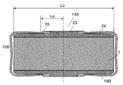
図7は、積層体加圧構造を有する燃料電池の断面図である。図8は図7に示す積層体加圧構造を構成する板状弾性体である板ばね10Bの側面図である。図8は積層スタック1と端板13Aを挿入前の板ばね10Bの状態を示している。本実施の形態では、2つの板ばね10Bの側面部分11Bに端板13Aを加圧するための突起部25が設けられている。それ以外の構成は図6の構成と同様である。
FIG. 7 is a cross-sectional view of a fuel cell having a laminate pressure structure. FIG. 8 is a side view of a
このように板ばね10Bの側面部分11Bにそれぞれ突起部25を設けることで、板ばね10Bで端板13Aに掛ける力の作用点が一義的に定まり、加圧力を安定させることができる。突起部25の位置Laを適切に設計することにより、端板13Aに作用する圧力を均一化させることができる。
Thus, by providing the
図9(a)は、積層スタック1と端板13Aと板ばね10Bの1/4の有限要素解析モデル図である。積層スタック1は3個の燃料電池の単位セル101、102、103を含む。図9(b)は有限要素解析結果であり、単位セル101、102、103の圧縮変形を積層スタック1の中心104からの距離に対して示したグラフである。図9(a)に示すモデルにおいて加圧前の各単位セルの厚さは0.65mmである。一方、加圧後の厚さは図9(b)に示すようにどの単位セル、どの位置においても0.5mm付近に分布している。このように単位セル101、102、103の圧縮変形量は、どの位置においてもほぼ一定の値となっている。
FIG. 9A is a 1/4 finite element analysis model diagram of the
図9(c)は3個の単位セルの圧縮応力分布を示している。いずれの単位電池も圧縮応力は0.20MPaから0.22MPaと一定の範囲に均一化されていることがわかる。 FIG. 9C shows the compressive stress distribution of three unit cells. It can be seen that the compressive stress is uniform in a certain range from 0.20 MPa to 0.22 MPa in any unit cell.
このように一定の圧縮応力の大きさと均一の圧縮分布を得るためには、端板13Aとの接触点である突起部25から積層スタック1の中心までの距離Laを、積層スタック1の幅Loの12%以上38%以下とすることが好ましい。突起部25の距離Laを変化させた有限要素法解析結果より、特に距離Laを幅Loの約1/4とすることが好ましいことがわかっている。
In order to obtain a constant compressive stress and a uniform compressive distribution in this way, the distance La from the
図9の有限要素解析は、板ばね10Bの側面部分11Bと底面部分12とがなす角度を予め約75度に設定し、突起部25の位置が積層スタック1の中心から積層スタック1の幅の約25%とした場合を示している。すなわち図7において、積層スタック1の中心から突起部25までの距離Laを、積層スタック1の幅Loの約1/4(25%)とすることで積層スタック1に作用する圧力分布を均一化することができることが示されている。
In the finite element analysis of FIG. 9, the angle formed by the
(実施の形態1)
図10は本発明の実施の形態1による積層体加圧構造を有する燃料電池の断面図、図11は図10に示す積層体加圧構造を構成する板状弾性体である板ばね10Cの側面図である。図11は積層スタック1と端板13Aを挿入前の板ばね10Cの状態を示している。本実施の形態では、2つの板ばね10Cは、側面部分11Cの末端で、側面部分11C同士が対向する方向に折り曲げられた折り返し部分26を有する。それ以外の構成は、図6の構成と同様である。
(Embodiment 1 )
FIG. 10 is a cross-sectional view of a fuel cell having a stacked body pressurizing structure according to
このように板ばね10Cの側面部分11Cの先端部分をそれぞれ折り曲げて折り返し部分26を設けることで、板ばね10Cのばね定数を小さくしてばね性を向上させることができる。また折り返し部分26を適切に設計することにより、端板13Aに掛ける力の作用点が一義的に定まり、加圧力を安定させることができる。
In this way, by providing the folded
なお図10に示すように折り返し部分26と端板13Aとの接触点から積層スタック1の中心までの距離Laを、積層スタック1の幅Loの12%以上38%以下とすることで積層スタック1に作用する圧力分布を均一化することができる。特に距離Laを幅Loの約1/4とすることが好ましい。
As shown in FIG. 10, the distance La from the contact point between the folded
(実施の形態2)
図12は、本発明の実施の形態2による積層体加圧構造を有する燃料電池の断面図である。図13(a)は図12に示す積層体加圧構造を構成する板状弾性体である板ばね10Dの上面図、図13(b)は図12に示す積層体加圧構造を構成する板状弾性体である板ばね10Dの側面図である。ただし、図13(a)、(b)は積層スタック1、端板13Aの挿入前の状態を示している。本実施の形態では、2つの板ばね10Dの側面部分11Dに開口部271が設けられている。そして板ばね10Dは、開口部271で囲まれた部分に側面部分11D同士が対向する方向に曲げ加工を施すことで形成された曲げ加工部27を有する。それ以外の構成は、図6の構成と同様である。
(Embodiment 2 )
FIG. 12 is a cross-sectional view of a fuel cell having a laminate pressure structure according to
開口部271は側面部分11Dを縁切加工することにより設けられ、開口部271で囲まれた内側部分を折り曲げ線272で折り曲げて曲げ加工部27を形成することで板ばね10Dのばね性を向上させている。
The
また曲げ加工部27の長さと丸みを適切に設計することにより、端板13Aに掛ける力の作用力と作用点が一義的に定まり、加圧力を安定させることができる。図12に示すように曲げ加工部27と端板13Aとの接触点から積層スタック1の中心までの距離Laを、積層スタック1の幅Loの12%以上38%以下とすることで積層スタック1に作用する圧力分布を均一化することができる。特に距離Laを幅Loの約1/4とすることが好ましい。
Further, by appropriately designing the length and roundness of the bending
(実施の形態3)
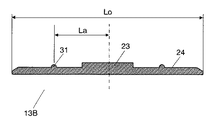
図14は、本発明の実施の形態3による積層体加圧構造を有する燃料電池の断面図である。図15は図14に示す積層体加圧構造を構成する端板13Bの断面図である。本実施の形態では、端板13Bの薄肉部24に突起31が設けられ、板ばね10が突起31に当たって端板13Bを挟持している。それ以外の構成は、図6の構成と同様である。
(Embodiment 3 )
FIG. 14 is a cross-sectional view of a fuel cell having a laminate pressurizing structure according to Embodiment 3 of the present invention. FIG. 15 is a cross-sectional view of the
このように端板13Bに突起31を設けることにより、端板13Bに掛ける力の作用点が一義的に定まり、加圧力を安定化することができる。特に図15に示すように端板13Bと板ばね10との接触点である突起31から積層スタック1の中心までの距離Laを、積層スタック1の幅Loの12%以上38%以下とすることで積層スタック1に作用する圧力分布を均一化することができる。特に距離Laを幅Loの約1/4とすることが好ましい。
Thus, by providing the
なお突起31は距離Laの前後に複数個設けてもよい。複数個設けることでさらに圧力分布を均一化することができる。
A plurality of
本発明による積層体の加圧構造では、積層体を挟持すると共に積層方向に加圧することができる。また板状弾性体で加圧部品のすべてを一体化することができ、ばね特性、省スペース性、組み立て性を同時に向上させることができる。このような積層体の加圧構造は発電素子である一次電池や燃料電池、または蓄電素子である二次電池やコンデンサを形成する各要素を積層してなる積層体に有用である。さらに単位発電素子または単位蓄電素子を積層してなる積層スタックにも有用である。 In the pressurizing structure of the laminate according to the present invention, the laminate can be sandwiched and pressed in the stacking direction. Further, all of the pressurizing parts can be integrated with the plate-like elastic body, and the spring characteristics, space saving, and assembly can be improved at the same time. Such a pressurizing structure of the laminated body is useful for a laminated body formed by laminating elements forming a primary battery or a fuel cell as a power generation element, or a secondary battery or a capacitor as a power storage element. Furthermore, it is also useful for a stacked stack in which unit power generation elements or unit storage elements are stacked.
1 積層スタック(積層体)
10,10A,10B,10C,10D 板ばね
11,11B,11C,11D 側面部分
12 底面部分
13,13A,13B 端板
23 厚肉部
24 薄肉部
25 突起部
26 折り返し部分
27 曲げ加工部
31 突起
71 積層体
72 端板
74,75 押圧板
76 ばね
77 ナット
78 締結ボルト
79 ワッシャー
86 皿ばね
96 コイルばね
101,102,103 単位セル
104 中心
271 開口部
272 折り曲げ線
1 Laminate stack (laminate)
10, 10A, 10B, 10C,
Claims (5)
前記積層体の上下に位置する一対の端板と、
前記端板を上下から挟持すると共に前記積層体を積層方向に加圧する板状弾性体とを備え、
前記板状弾性体の断面形状が底面部分と前記底面部分から曲げられた2つの側面部分とを有する溝型であり、さらに、前記板状弾性体は、前記側面部分の末端で前記側面部分同士が対向する方向に折り曲げられた折り返し部分を有し、
前記端板に厚肉部を設け、前記厚肉部に、前記板状弾性体の前記折り返し部分の先端部を当接させることを特徴とする積層体の加圧構造。 A laminated body formed by laminating elements for forming a power generation element or a power storage element, or a pressurizing structure of a laminated body that is a laminated stack formed by laminating a unit power generation element or a unit power storage element,
A pair of end plates positioned above and below the laminate;
A plate-like elastic body that clamps the end plate from above and below and pressurizes the laminated body in the laminating direction;
A cross-sectional shape of the plate-like elastic body is a groove type having a bottom surface portion and two side surface portions bent from the bottom surface portion, and the plate-like elastic body is formed between the side surface portions at the end of the side surface portion. Has a folded portion folded in the opposite direction,
A pressurizing structure for a laminate, wherein the end plate is provided with a thick portion, and a tip portion of the folded portion of the plate-like elastic body is brought into contact with the thick portion.
前記積層体の上下に位置する一対の端板と、
前記端板を上下から挟持すると共に前記積層体を積層方向に加圧する板状弾性体とを備え、
前記板状弾性体の断面形状が底面部分と前記底面部分から曲げられた2つの側面部分とを有する溝型であり、さらに、前記板状弾性体の前記側面部分に開口部が設けられており、前記板状弾性体は、前記開口部で囲まれた部分に前記側面部分同士が対向する方向に曲げ加工を施すことで形成された曲げ加工部を有し、
前記端板に厚肉部を設け、前記厚肉部に、前記板状弾性体の前記側面部分の先端部を当接させることを特徴とする積層体の加圧構造。 A laminated body formed by laminating elements for forming a power generation element or a power storage element, or a pressurizing structure of a laminated body that is a laminated stack formed by laminating a unit power generation element or a unit power storage element,
A pair of end plates positioned above and below the laminate;
A plate-like elastic body that clamps the end plate from above and below and pressurizes the laminated body in the laminating direction;
A cross-sectional shape of the plate-like elastic body is a groove type having a bottom surface portion and two side surface portions bent from the bottom surface portion, and an opening is provided in the side surface portion of the plate-like elastic body. The plate-like elastic body has a bent portion formed by bending a portion surrounded by the opening portion in a direction in which the side surface portions face each other.
A pressurizing structure for a laminate, wherein a thick portion is provided on the end plate, and a tip portion of the side surface portion of the plate-like elastic body is brought into contact with the thick portion.
前記積層体の上下に位置する一対の端板と、
前記端板を上下から挟持すると共に前記積層体を積層方向に加圧する板状弾性体とを備え、
前記板状弾性体の断面形状が底面部分と前記底面部分から曲げられた2つの側面部分とを有する溝型であり、
前記端板に突起が設けられ、前記板状弾性体は前記突起において前記端板を挟持され、
前記端板に厚肉部を設け、前記厚肉部に、前記板状弾性体の前記側面部分の先端部を当接させることを特徴とする積層体の加圧構造。 A laminated body formed by laminating elements for forming a power generation element or a power storage element, or a pressurizing structure of a laminated body that is a laminated stack formed by laminating a unit power generation element or a unit power storage element,
A pair of end plates positioned above and below the laminate;
A plate-like elastic body that clamps the end plate from above and below and pressurizes the laminated body in the laminating direction;
The cross-sectional shape of the plate-like elastic body is a groove type having a bottom surface portion and two side surface portions bent from the bottom surface portion,
A projection is provided on the end plate, and the plate-like elastic body sandwiches the end plate at the projection,
A pressurizing structure for a laminate, wherein a thick portion is provided on the end plate, and a tip portion of the side surface portion of the plate-like elastic body is brought into contact with the thick portion.
The angle formed by the bottom surface portion and the side surface portion of the plate-like elastic body in a state before pressurizing the laminated body is set to 65 degrees or more and 85 degrees or less. Pressurized structure of the laminate.
Priority Applications (1)
| Application Number | Priority Date | Filing Date | Title |
|---|---|---|---|
| JP2007269920A JP5256683B2 (en) | 2007-10-17 | 2007-10-17 | Pressure structure of laminate |
Applications Claiming Priority (1)
| Application Number | Priority Date | Filing Date | Title |
|---|---|---|---|
| JP2007269920A JP5256683B2 (en) | 2007-10-17 | 2007-10-17 | Pressure structure of laminate |
Publications (3)
| Publication Number | Publication Date |
|---|---|
| JP2009099383A JP2009099383A (en) | 2009-05-07 |
| JP2009099383A5 JP2009099383A5 (en) | 2010-09-24 |
| JP5256683B2 true JP5256683B2 (en) | 2013-08-07 |
Family
ID=40702204
Family Applications (1)
| Application Number | Title | Priority Date | Filing Date |
|---|---|---|---|
| JP2007269920A Expired - Fee Related JP5256683B2 (en) | 2007-10-17 | 2007-10-17 | Pressure structure of laminate |
Country Status (1)
| Country | Link |
|---|---|
| JP (1) | JP5256683B2 (en) |
Cited By (1)
| Publication number | Priority date | Publication date | Assignee | Title |
|---|---|---|---|---|
| US9416652B2 (en) | 2013-08-08 | 2016-08-16 | Vetco Gray Inc. | Sensing magnetized portions of a wellhead system to monitor fatigue loading |
Families Citing this family (13)
| Publication number | Priority date | Publication date | Assignee | Title |
|---|---|---|---|---|
| JP5625294B2 (en) * | 2009-09-18 | 2014-11-19 | 日産自動車株式会社 | Battery module |
| KR101173870B1 (en) | 2010-08-18 | 2012-08-14 | 에스비리모티브 주식회사 | Battery module |
| US9343772B2 (en) | 2010-10-08 | 2016-05-17 | Samsung Sdi Co., Ltd. | Rechargeable battery |
| CA2822785C (en) | 2010-12-21 | 2015-01-13 | Nissan Motor Co., Ltd. | Fuel cell stack |
| JP5691646B2 (en) * | 2011-03-01 | 2015-04-01 | 日産自動車株式会社 | Fuel cell stack |
| JP6018463B2 (en) * | 2012-09-18 | 2016-11-02 | 株式会社東芝 | Fuel cell |
| KR20140098490A (en) * | 2013-01-31 | 2014-08-08 | 삼성에스디아이 주식회사 | Rechargeable battery |
| GB2516268A (en) * | 2013-07-17 | 2015-01-21 | Intelligent Energy Ltd | Fuel cell stack assembly |
| GB2516264A (en) * | 2013-07-17 | 2015-01-21 | Intelligent Energy Ltd | Fuel cell stack assembly and method of assembly |
| GB2516270A (en) * | 2013-07-17 | 2015-01-21 | Intelligent Energy Ltd | Fuel cell stack assembly |
| KR102018721B1 (en) * | 2016-05-31 | 2019-09-09 | 주식회사 엘지화학 | Battery module, battery pack comprising the battery module and vehicle comprising the battery pack |
| KR102267606B1 (en) * | 2017-11-30 | 2021-06-21 | 주식회사 엘지에너지솔루션 | Battery module an initial pressing force reinforcing structure for a battery cell assembly and Method for manufacturing the same |
| CN114142147A (en) * | 2021-11-12 | 2022-03-04 | 捷威动力工业嘉兴有限公司 | Electricity core piles up into shell equipment |
Family Cites Families (3)
| Publication number | Priority date | Publication date | Assignee | Title |
|---|---|---|---|---|
| JPH02120821U (en) * | 1989-03-17 | 1990-09-28 | ||
| JPH0992324A (en) * | 1995-07-20 | 1997-04-04 | Toyota Motor Corp | Cell module and fuel cell |
| JP2008311165A (en) * | 2007-06-18 | 2008-12-25 | Panasonic Corp | Fuel cell stack, and fuel cell using the same |
-
2007
- 2007-10-17 JP JP2007269920A patent/JP5256683B2/en not_active Expired - Fee Related
Cited By (1)
| Publication number | Priority date | Publication date | Assignee | Title |
|---|---|---|---|---|
| US9416652B2 (en) | 2013-08-08 | 2016-08-16 | Vetco Gray Inc. | Sensing magnetized portions of a wellhead system to monitor fatigue loading |
Also Published As
| Publication number | Publication date |
|---|---|
| JP2009099383A (en) | 2009-05-07 |
Similar Documents
| Publication | Publication Date | Title |
|---|---|---|
| JP5256683B2 (en) | Pressure structure of laminate | |
| JP2001167745A (en) | Pressure structure for cell laminated structure | |
| JP4621513B2 (en) | Fuel cell stack | |
| US20080124625A1 (en) | Casing For a Sealed Battery | |
| KR20140030271A (en) | Fuel cell, and method for production of fuel cell | |
| EP3800689B1 (en) | Secondary battery, battery module and electric vehicle | |
| JP2005044688A (en) | Fuel cell stack | |
| US9190686B2 (en) | Fuel cell stack | |
| EP2898562B1 (en) | A fuel cell stack assembly | |
| JP2009182001A (en) | Cell stack structure | |
| US20050255362A1 (en) | Fuel cell and related manufacturing method | |
| WO2018101079A1 (en) | Secondary cell and cell pack | |
| JP2016062852A (en) | Assembling method of fuel cell stack | |
| WO2003094275A1 (en) | Method and apparatus for providing a uniform fuel cell stack structure | |
| JP6612814B2 (en) | Method and apparatus for manufacturing fuel cell stack | |
| JP2005141935A (en) | Fuel cell stack | |
| JP5211539B2 (en) | Fuel cell stack | |
| JP4789478B2 (en) | Fuel cell stack and assembly method thereof | |
| JP4865238B2 (en) | Fuel cell stack | |
| JP4911951B2 (en) | Fuel cell and manufacturing method thereof | |
| JP4417204B2 (en) | Fuel cell stack | |
| JP2010212149A (en) | Fuel cell stack | |
| JP2006252972A (en) | Fuel cell stack and manufacturing method for the same | |
| JP5214270B2 (en) | Fuel cell | |
| JP4197931B2 (en) | Tightening structure of polymer electrolyte fuel cell stack |
Legal Events
| Date | Code | Title | Description |
|---|---|---|---|
| A521 | Written amendment |
Free format text: JAPANESE INTERMEDIATE CODE: A523 Effective date: 20100806 |
|
| A621 | Written request for application examination |
Free format text: JAPANESE INTERMEDIATE CODE: A621 Effective date: 20100806 |
|
| RD01 | Notification of change of attorney |
Free format text: JAPANESE INTERMEDIATE CODE: A7421 Effective date: 20100914 |
|
| A977 | Report on retrieval |
Free format text: JAPANESE INTERMEDIATE CODE: A971007 Effective date: 20121112 |
|
| A131 | Notification of reasons for refusal |
Free format text: JAPANESE INTERMEDIATE CODE: A132 Effective date: 20121120 |
|
| RD01 | Notification of change of attorney |
Free format text: JAPANESE INTERMEDIATE CODE: A7421 Effective date: 20121213 |
|
| A521 | Written amendment |
Free format text: JAPANESE INTERMEDIATE CODE: A523 Effective date: 20121214 |
|
| A131 | Notification of reasons for refusal |
Free format text: JAPANESE INTERMEDIATE CODE: A131 Effective date: 20130108 |
|
| A521 | Written amendment |
Free format text: JAPANESE INTERMEDIATE CODE: A523 Effective date: 20130306 |
|
| TRDD | Decision of grant or rejection written | ||
| A01 | Written decision to grant a patent or to grant a registration (utility model) |
Free format text: JAPANESE INTERMEDIATE CODE: A01 Effective date: 20130326 |
|
| A61 | First payment of annual fees (during grant procedure) |
Free format text: JAPANESE INTERMEDIATE CODE: A61 Effective date: 20130408 |
|
| FPAY | Renewal fee payment (event date is renewal date of database) |
Free format text: PAYMENT UNTIL: 20160502 Year of fee payment: 3 |
|
| LAPS | Cancellation because of no payment of annual fees |