JP5253186B2 - Conveying apparatus, image forming apparatus, and control method - Google Patents
Conveying apparatus, image forming apparatus, and control method Download PDFInfo
- Publication number
- JP5253186B2 JP5253186B2 JP2009001828A JP2009001828A JP5253186B2 JP 5253186 B2 JP5253186 B2 JP 5253186B2 JP 2009001828 A JP2009001828 A JP 2009001828A JP 2009001828 A JP2009001828 A JP 2009001828A JP 5253186 B2 JP5253186 B2 JP 5253186B2
- Authority
- JP
- Japan
- Prior art keywords
- recording sheet
- line sensor
- detection
- edge
- output level
- Prior art date
- Legal status (The legal status is an assumption and is not a legal conclusion. Google has not performed a legal analysis and makes no representation as to the accuracy of the status listed.)
- Expired - Fee Related
Links
Images


Description
本発明は、搬送装置、画像形成装置及び制御方法に関する。 The present invention relates to a conveyance device, an image forming apparatus, and a control method.
複写機などの画像形成装置の普及に伴って、かかる画像形成装置には高速化及び高画質化がますます要求されるようになってきている。かかる要求を満足するために、記録シート(記録紙)の斜行及び横レジずれを補正する搬送装置を備え、感光体、或いは、転写体に形成されたトナー像に対して記録シートを正確に位置合わせすることができる画像形成装置が提案されている。 With the widespread use of image forming apparatuses such as copying machines, such image forming apparatuses are increasingly required to have higher speed and higher image quality. In order to satisfy these requirements, a conveyance device for correcting skew and lateral registration deviation of the recording sheet (recording paper) is provided, and the recording sheet is accurately applied to the toner image formed on the photosensitive member or the transfer member. An image forming apparatus capable of aligning has been proposed.
例えば、アクティブレジストレーション方式を用いた搬送装置は、記録シートの搬送を停止させないため、生産性を落とすことなく斜行及び横レジずれを補正することができる(特許文献1参照)。アクティブレジストレーション方式では、まず、記録シートの搬送方向に対して直交する幅方向に離間して配置された2つのセンサを記録シートの先端部が通過したときに、かかる2つのセンサから出力される検出信号に基づいて記録シートの斜行を検出する。そして、幅方向に、且つ、同軸上に離間して配置され、互いに独立して回転(駆動)する2つの補正ローラのそれぞれの搬送速度を、記録シートの斜行量に応じて異ならせることで記録シートの斜行を補正する。換言すれば、記録シートの斜行量に基づいて、2つの補正ローラのそれぞれを駆動するモータの回転速度を制御して、一方の補正ローラの搬送速度を他方の補正ローラの搬送速度よりも遅く、又は、速くすることで記録シートの斜行を補正する。 For example, a conveyance device using an active registration method does not stop conveyance of a recording sheet, and can correct skew and lateral registration deviation without reducing productivity (see Patent Document 1). In the active registration method, first, when the leading end of the recording sheet passes through two sensors that are spaced apart from each other in the width direction perpendicular to the conveyance direction of the recording sheet, the two sensors output the two. The skew of the recording sheet is detected based on the detection signal. Then, the respective conveying speeds of the two correction rollers arranged in the width direction and spaced apart on the same axis and rotated (driven) independently of each other are made different according to the skew amount of the recording sheet. Correct the skew of the recording sheet. In other words, the rotation speed of the motor that drives each of the two correction rollers is controlled based on the skew amount of the recording sheet, so that the conveyance speed of one correction roller is slower than the conveyance speed of the other correction roller. Alternatively, the skew of the recording sheet is corrected by increasing the speed.
このように、アクティブレジストレーション方式は、記録シートの搬送を停止させることなく記録シートの斜行を補正することができるため、記録シートの間隔を他の方式よりも狭くして記録シートの搬送効率を向上させることができる。従って、アクティブレジストレーション方式を用いた搬送装置は、画像形成装置における画像形成のプロセス速度を速くすることなく、プリント速度の実質的な向上を図ることができる。 As described above, since the active registration method can correct the skew of the recording sheet without stopping the recording sheet conveyance, the recording sheet conveyance efficiency is reduced by making the recording sheet interval narrower than other methods. Can be improved. Therefore, the conveying apparatus using the active registration method can substantially improve the printing speed without increasing the image forming process speed in the image forming apparatus.
斜行が補正された記録シートは、幅方向のずれ(横レジずれ)が更に補正される。横レジずれの補正においては、幅方向におけるシートのエッジを検出するためのラインセンサからの出力を所定の閾値を用いて2値化する。そして、2値化された値の変化点(1から0或いは0から1への変化)を記録シートのエッジと判断する。更に、エッジの位置と横レジの目標位置との差分(横レジずれ量)を算出すると共に、横レジずれの方向を判定して、記録シートを搬送するローラをシフトさせることで横レジずれを補正する。 In the recording sheet in which the skew feeding is corrected, the deviation in the width direction (lateral registration deviation) is further corrected. In correcting the lateral misregistration, the output from the line sensor for detecting the edge of the sheet in the width direction is binarized using a predetermined threshold. The change point of the binarized value (change from 1 to 0 or 0 to 1) is determined as the edge of the recording sheet. Further, the difference between the edge position and the lateral registration target position (lateral registration deviation amount) is calculated, the direction of the lateral registration deviation is judged, and the lateral registration deviation is shifted by shifting the roller for conveying the recording sheet. to correct.
以下、図5を参照して、従来の搬送装置を具体的に説明する。図5は、アクティブレジストレーション方式を用いた従来の搬送装置1000を示す概略ブロック図である。搬送装置1000は、レジ補正前ローラ1010と、斜行検出センサ1020L及び1020Rと、斜行検出部1030と、斜行補正ローラ1040L及び1040Rと、斜行制御部1050とを有する。更に、搬送装置1000は、エッジ検出タイミングセンサ1060と、横レジずれ量検出部1070と、ラインセンサ1080と、シフトローラ1090と、タイミングセンサ1100と、シフト制御部1110とを有する。
Hereinafter, a conventional transfer apparatus will be described in detail with reference to FIG. FIG. 5 is a schematic block diagram showing a
搬送装置1000において、記録シートPSの先端部は、レジ補正前ローラ1010が記録シートPSを搬送している間に、斜行検出センサ1020L及び1020Rによって検出される。斜行検出部1030は、2つの斜行検出センサ1020L及び1020Rの検出時間差から斜行量を算出すると共に、斜行検出センサ1020L及び1020Rのどちらが先に記録シートPSの先端部を検出したのかで斜行方向を判断する。そして、斜行補正ローラ1040L及び1040Rが記録シートPSを挟持すると、斜行制御部1050は、斜行検出部1030によって算出された斜行量及び斜行方向に基づいて、斜行補正ローラ1040L又は1040Rを減速させる。これにより、記録シートPSの斜行が補正される。
In the
記録シートPSの搬送が進み、記録シートの先端部がエッジ検出タイミングセンサ1060を通過した時点で、横レジずれ量検出部1070は、記録シートPSの中央付近でのラインセンサ1080の出力レベル(感度)が目標レベルを達成しているかを確認する。例えば、ラインセンサ1080が赤(R)、緑(G)、青(B)の3色のLEDを有している場合、これらのLEDを単独発光させるか、2色発光させるか、或いは、全色発光させるかによって、ラインセンサ1080の出力レベルは変化する。従って、LEDの発光パターンは、ラインセンサ1080の出力レベルが目標レベルを達成する適正な発光パターンに設定(決定)される。また、かかる発光パターンで記録シートPSがラインセンサ1080の位置に搬送されていない状態と搬送されている状態とでのラインセンサ1080のそれぞれの出力レベルの中間レベルがラインセンサ1080の出力に対する2値化の閾値となる。なお、記録シートPSがラインセンサ1080の位置に搬送されていない状態では、ラインセンサ1080は記録シートPSの搬送路(下地)を検出することになる。
When the conveyance of the recording sheet PS advances and the leading edge of the recording sheet passes the edge
更に、記録シートPSの搬送が進み、シフトローラ1090が記録シートPSを挟持すると、上述した閾値を用いた記録シートPSのエッジ検出が複数回実行される。横レジずれ量検出部1070は、複数回のエッジ検出の平均値と横レジの目標位置との差分(横レジずれ量)を算出すると共に、横レジずれの方向を判断する。そして、記録シートPSがタイミングセンサ1100を通過した時点で、シフト制御部1110は、横レジずれ量検出部1070によって算出された横レジずれ量及び横レジずれ方向に基づいて、シフトローラ1090をシフトさせる。これにより、記録シートPSの横レジずれが補正される。
しかし、ラインセンサの出力に対する2値化の閾値を、搬送路を検出した際とラインセンサの位置に搬送された記録シートを検出した際におけるラインセンサの出力レベルの中間レベルに設定(固定)すると、記録シートのエッジの検出の際に問題が生じてしまう。 However, if the binarization threshold for the output of the line sensor is set (fixed) to an intermediate level of the output level of the line sensor when the conveyance path is detected and the recording sheet conveyed to the position of the line sensor is detected (fixed) This causes a problem when detecting the edge of the recording sheet.
例えば、図6(a)に示すように、記録シートがラインセンサの焦点位置に位置するように搬送されている場合には、記録シートのエッジを誤差なく検出することができる。しかし、図6(b)に示すように、記録シートがラインセンサの焦点位置からずれて搬送されている場合には、ラインセンサからの出力波形が鈍ると共に出力レベルも低下する。従って、記録シートがラインセンサの焦点位置からずれて搬送されている場合には、上述した閾値で記録シートのエッジを検出すると、検出結果に誤差(検出誤差)が生じてしまう。即ち、検出される記録シートのエッジの位置が実際のエッジの位置からずれてしまう。なお、図6(a)及び図6(b)は、記録シートの搬送方向から見た記録シートとラインセンサ(の焦点位置)との位置関係を示している。 For example, as shown in FIG. 6A, when the recording sheet is conveyed so as to be positioned at the focal position of the line sensor, the edge of the recording sheet can be detected without error. However, as shown in FIG. 6B, when the recording sheet is conveyed out of the focus position of the line sensor, the output waveform from the line sensor becomes dull and the output level also decreases. Accordingly, when the recording sheet is conveyed out of the focus position of the line sensor, if the edge of the recording sheet is detected with the above-described threshold, an error (detection error) occurs in the detection result. That is, the detected edge position of the recording sheet is deviated from the actual edge position. 6A and 6B show the positional relationship between the recording sheet and the line sensor (the focal position thereof) as viewed from the recording sheet conveyance direction.
また、横レジずれの補正においては、高速化を実現するために、記録シートのエッジを検出した直後にシフトローラをシフトさせなければならないため、斜行補正ローラとシフトローラとは、ある程度の距離を離して配置する必要がある。従って、記録シートが小サイズ(例えば、レターサイズ)である場合には、エッジ検出の際に記録シートを挟持するローラがシフトローラのみとなる。そのため、搬送中の風圧や記録シートの特性などによって、ラインセンサの焦点位置からの記録シートのずれ量は、複数回のエッジ検出のそれぞれで異なることになる。例えば、図7(a)乃至図7(d)に示すように、記録シートの搬送に従って(記録シートの後端をラインセンサが検出する状態になるにつれて)、記録シートはラインセンサの焦点位置からずれてしまうため、検出誤差が徐々に大きくなってしまう。なお、図7(a)乃至図7(d)は、記録シートの搬送方向に直交する方向から見た記録シートとラインセンサ(の焦点位置)との位置関係を示している。 Also, in correcting lateral misregistration, the shift roller must be shifted immediately after detecting the edge of the recording sheet in order to achieve high speed. Therefore, the skew correction roller and the shift roller have a certain distance. Need to be placed apart. Therefore, when the recording sheet is a small size (for example, letter size), the only roller that sandwiches the recording sheet at the time of edge detection is the shift roller. For this reason, the amount of deviation of the recording sheet from the focal position of the line sensor differs for each of a plurality of edge detections depending on the wind pressure during conveyance and the characteristics of the recording sheet. For example, as shown in FIGS. 7A to 7D, as the recording sheet is conveyed (as the line sensor detects the trailing edge of the recording sheet), the recording sheet moves from the focal position of the line sensor. As a result, the detection error gradually increases. 7A to 7D show the positional relationship between the recording sheet and the line sensor (the focal position thereof) viewed from the direction orthogonal to the recording sheet conveyance direction.
そこで、本発明は、このような従来技術の課題に鑑みて、記録シートの横レジずれを高精度に検出及び補正することができる技術を提供することを例示的目的とする。 In view of the above-described problems of the related art, an object of the present invention is to provide a technique capable of detecting and correcting a lateral registration shift of a recording sheet with high accuracy.
上記目的を達成するために、本発明の一側面としての搬送装置は、記録シートを搬送する搬送装置であって、前記記録シートの搬送路に配置され、前記記録シートを検出するラインセンサと、前記ラインセンサの出力に基づいて、前記記録シートの搬送方向に直交する幅方向における前記記録シートのエッジの位置を検出する検出手段と、前記記録シートを前記幅方向へシフトさせるシフト手段と、前記検出手段によって検出された前記記録シートのエッジの位置に基づいて、前記幅方向における前記記録シートのエッジの目標位置からのずれを示すシフト量及びシフト方向を算出する算出手段と、前記算出手段によって算出されたシフト量及びシフト方向に基づいて、前記幅方向における前記記録シートのエッジが前記目標位置に一致するように、前記シフト手段を制御する制御手段と、を有し、前記検出手段は、前記記録シートが前記ラインセンサの位置に搬送されていない状態での前記ラインセンサの出力レベルと、前記記録シートが前記ラインセンサの位置に搬送されている状態での前記ラインセンサがシートを検出している部分の出力レベルとの中間レベルを閾値として前記ラインセンサの出力を2値化して、2値化した値が変化する位置を前記記録シートのエッジの位置として検出し、前記記録シートが前記ラインセンサの位置を搬送されている間に前記記録シートのエッジの位置の検出を複数回実行する場合において、当該複数回の検出のそれぞれの検出において前記ラインセンサがシートを検出している部分の出力レベルに基づいてそれぞれの検出の次の検出における閾値を決定することを特徴とする。 To achieve the above object, the transport apparatus according to one aspect of the present invention, there is provided a conveying device for conveying the recording sheet, it is disposed to the transport path of the recording sheet, and Lula-sensor to detect the recording sheet Detecting means for detecting the position of the edge of the recording sheet in the width direction orthogonal to the conveyance direction of the recording sheet based on the output of the line sensor; and shifting means for shifting the recording sheet in the width direction; Calculation means for calculating a shift amount and a shift direction indicating a deviation from the target position of the edge of the recording sheet in the width direction based on the position of the edge of the recording sheet detected by the detection means; and the calculation means The edge of the recording sheet in the width direction matches the target position based on the shift amount and shift direction calculated by Sea urchin, and a control means for controlling said shifting means, said detecting means, an output level of said line sensor in a state where the recording sheet is not conveyed to the position of the line sensor, the recording sheet A value obtained by binarizing the output of the line sensor with the intermediate level of the output level of the portion where the line sensor is detecting the sheet being conveyed to the position of the line sensor as a threshold value Is detected as the position of the edge of the recording sheet, and the detection of the position of the edge of the recording sheet is performed a plurality of times while the recording sheet is being conveyed through the position of the line sensor. All the subsequent detection of the respective detecting the line sensor at each of the detection of a plurality of detection based on the output level of the part that detects the sheet And determining a that threshold.
本発明の更なる目的又はその他の側面は、以下、添付図面を参照して説明される好ましい実施形態によって明らかにされるであろう。 Further objects and other aspects of the present invention will become apparent from the preferred embodiments described below with reference to the accompanying drawings.
本発明によれば、例えば、記録シートの横レジずれ(記録シートの搬送方向に直交する方向のずれ)を高精度に検出及び補正する搬送装置を提供することができる。 According to the present invention, for example, it is possible to provide a conveyance device that detects and corrects a lateral registration deviation (a deviation in a direction perpendicular to the conveyance direction of the recording sheet) of the recording sheet with high accuracy.
以下、添付図面を参照して、本発明の好適な実施の形態について説明する。なお、各図において、同一の部材については同一の参照番号を付し、重複する説明は省略する。 DESCRIPTION OF EXEMPLARY EMBODIMENTS Hereinafter, preferred embodiments of the invention will be described with reference to the accompanying drawings. In addition, in each figure, the same reference number is attached | subjected about the same member and the overlapping description is abbreviate | omitted.
図1A及び図1Bは、本発明の一側面としての搬送装置1を示す概略ブロック図である。搬送装置1は、記録シートPSを搬送する装置であって、記録シートPSに画像を形成する画像形成部を備える画像形成装置(例えば、複写機、ファクシミリ、プリンタ、複合機など)の搬送装置として適用することができる。 1A and 1B are schematic block diagrams showing a transport apparatus 1 as one aspect of the present invention. The conveyance device 1 is a device that conveys a recording sheet PS, and is a conveyance device of an image forming apparatus (for example, a copier, a facsimile, a printer, a multifunction machine, etc.) that includes an image forming unit that forms an image on the recording sheet PS. Can be applied.
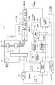
搬送装置1は、図1Aに示すように、ラインセンサ101と、シフトローラ102と、センサ103と、遅延部104と、制御信号生成部105と、A/D変換部106と、暫定閾値算出部107とを有する。更に、搬送装置1は、閾値算出部108と、エッジ位置検出部109と、シフト算出部110と、センサ111と、シフト制御部112と、ドライバ113と、LEDドライバ120とを有する。なお、図1Aには、記録シートPSの横レジずれ(記録シートPSの搬送方向に直交する幅方向のずれ)の補正に関連する構成のみを示している。但し、搬送装置1は、図1Bに示すように、記録シートPSの斜行の補正に関連するレジ補正前ローラ131、斜行検出センサ132L及び132R、斜行検出部133、斜行補正ローラ134L及び134R、及び、斜行制御部135も有する。
As shown in FIG. 1A, the conveyance device 1 includes a
レジ補正前ローラ131、斜行検出センサ132L及び132R、斜行検出部133、斜行補正ローラ134L及び134R及び斜行制御部135の機能及び構成は、従来技術(図5)と同様である。斜行検出センサ132L及び132Rは、レジ補正前ローラ131が記録シートPSを搬送している間に記録シートPSの先端部を検出する。また、斜行検出部133は、斜行検出センサ132L及び132Rの検出結果に基づいて、記録シートPSの斜行量を算出すると共に、記録シートPSの斜行方向を判断する。そして、斜行検出部133で算出された斜行量及び斜行方向に基づいて、斜行制御部135は、記録シートPSを挟持する斜行補正ローラ134L及び134Rを減速させて、記録シートPSの斜行を補正する。
The functions and configurations of the
センサ103は、記録シートPS及び記録シートPSの搬送路の中央部付近を検出することができるように配置され、記録シートPSの先端部を検出する。センサ103が記録シートPSの先端部を検出すると、ラインセンサ101、横レジずれ量検出部、センサ111、シフト制御部112、シフトローラ102などによって、記録シートPSの横レジずれが補正される。ここで、横レジずれ量検出部は、暫定閾値算出部107、閾値算出部108、エッジ位置検出部109、シフト算出部110などを含み、幅方向における記録シートPSのエッジと目標位置との差分(横レジずれ量)を算出すると共に、横レジずれの方向を判断する。なお、記録シートPSの横レジずれの補正の具体的な動作については、後述する搬送装置1の搬送動作において詳細に説明する。
The
また、ラインセンサ101は、記録シートPSに対して光を発光するLEDと、記録シートPS、或いは、記録シートPSの搬送路(下地)で反射された光を受光する複数の画素(センサ素子)とで構成される。ラインセンサ101は、少なくとも、幅方向の記録シートPSの一方のエッジから記録シートPSの中央付近までの領域を検出することができるように配置される。従って、ラインセンサ101は、記録シートPSがラインセンサ101の位置に搬送されている状態では記録シートPSを検出し、記録シートPSがラインセンサ101の位置に搬送されていない状態では記録シートPSの搬送路(下地)を検出する。本実施形態では、幅方向における記録シートPSのエッジは、ラインセンサ101からの出力を後述する閾値を用いて2値化し、かかる2値化された値の変化点とする。なお、ラインセンサ101は、記録シートPSの中央付近での出力レベル(感度)が目標レベルを達成するように、LEDの発光パターンが設定されている。
The
以下、図1A及び図2を参照して、搬送装置1を構成する各部と共に、搬送装置1の搬送動作について説明する。図2は、搬送装置1の搬送動作を説明するためのフローチャートである。搬送装置1の搬送動作は、電源が投入されてシステムリセットされた後に開始される。かかる搬送処理は、制御信号生成部105が搬送装置1の各部に制御信号を出力する(即ち、搬送装置1の各部を統括的に制御する)ことによって実行される。但し、搬送装置1は、上述したように、記録シートPSの斜行の補正に関連する搬送動作については従来と同様であるため、ここでは、記録シートPSの横レジずれの補正に関連する搬送動作のみについて説明する。
Hereinafter, with reference to FIG. 1A and FIG. 2, the conveying operation of the conveying device 1 will be described together with each part constituting the conveying device 1. FIG. 2 is a flowchart for explaining the transport operation of the transport apparatus 1. The transport operation of the transport device 1 is started after the power is turned on and the system is reset. Such a conveyance process is executed when the control
図2を参照するに、制御信号生成部105は、イニシャルライズのトリガ(イニシャルトリガ)が入力されたかどうかを判定する(S202)。イニシャルトリガが入力されていなければ、イニシャルトリガが入力されるまで待機する。
Referring to FIG. 2, the control
イニシャルトリガが入力されると、制御信号生成部105は、同期信号及びラインセンサ101に内蔵されたLEDを発光させるためのイネーブル信号を生成(出力)する(S204)。同期信号は、ラインセンサ101に直接入力される。イネーブル信号は、LEDドライバ120を介して、ラインセンサ101に入力される。
When the initial trigger is input, the control
同期信号及びイネーブル信号が入力されたラインセンサ101は、かかる同期信号及びイネーブル信号に基づいて、LEDを発光させる(S206)。これにより、ラインセンサ101は、記録シートPSの搬送路(の下地)に対応した検出信号を出力する。
The
図3は、同期信号、イネーブル信号、ラインセンサ101の出力の関係(タイミングチャート)の一例を示す図である。ラインセンサ101は、図3に示すように、イネーブル信号ES1及びES2のそれぞれに対応してLEDを発光させ、画素(センサ素子)の電荷のストレージを実行して検出信号DS1及びDS2を出力する。
FIG. 3 is a diagram illustrating an example of a relationship (timing chart) between the synchronization signal, the enable signal, and the output of the
ラインセンサ101のLEDの発光が終了した後、制御信号生成部105は、同期信号を再び生成(出力)する(S208)。
After the light emission of the LED of the
A/D変換部106は、ラインセンサ101からの検出信号をデジタルデータに変換し、所定数のデジタルデータを出力レベル算出部121にスタックする。出力レベル算出部121は、A/D変換部106からスタックされた所定数のデジタルデータの平均値を、ラインセンサ101が搬送路を検出した際の出力レベルとして算出(出力)する(S210)。
The A /
制御信号生成部105は、センサ103が記録シートPSの先端部を検出したかどうかを判定する(S212)。センサ103が記録シートPSの先端部を検出していなければ、センサ103が記録シートPSの先端部を検出するまで待機する。なお、センサ103は、記録シートPSの先端部を検出すると、記録シートPSの先端部を検出したことを示す信号を制御信号生成部105及び暫定閾値算出部107に送信する。
The
センサ103が記録シートPSの先端部を検出すると、制御信号生成部105は、センサ103からの信号をトリガとして、同期信号、イネーブル信号及びセンサクロックを生成(出力)する(S214)。同期信号及びセンサクロックは、ラインセンサ101に直接入力される。イネーブル信号は、LEDドライバ120を介して、ラインセンサ101に入力される。
When the
ラインセンサ101は、制御信号生成部105からのイネーブル信号が入力されている間、LEDを発光させる(S216)。これにより、ラインセンサ101は、記録シートPSを検出した際の検出信号を出力する。
The
ラインセンサ101のLEDの発光が終了した後、制御信号生成部105は、同期信号を再び生成(出力)する(S218)。
After the light emission of the LED of the
暫定閾値算出部107は、ラインセンサ101からA/D変換部106を介して入力されるデジタルデータのうち記録シートPSの存在が確定される領域(即ち、ラインセンサ101が記録シートPSを検出した際)の出力レベルを抽出する(S220)。また、暫定閾値算出部107は、暫定閾値(設定値)を算出する(S222)。具体的には、暫定閾値算出部107は、ラインセンサ101が搬送路を検出した際の出力レベルと、S220で抽出したラインセンサ101が記録シートPSを検出した際の出力レベルとの中間レベルを、暫定閾値(設定値)として算出する。
The temporary threshold
一方、遅延部104には、記録シートPSの斜行を補正した後で、幅方向における記録シートPSのエッジ(の位置)の検出が開始されるように、遅延量が設定されている。遅延部104は、設定された遅延量を制御信号生成部105及び閾値算出部108に出力し、制御信号生成部105は、遅延部104から遅延量が入力されたかどうかを判定する(S224)。遅延部104から遅延量が入力されていなければ、遅延部104から遅延量が入力されるまで待機する。
On the other hand, a delay amount is set in the
遅延部104から遅延量が入力されたら、制御信号生成部105は、同期信号、イネーブル信号及びセンサクロックを生成(出力)する(S226)。
When the delay amount is input from the
ラインセンサ101は、制御信号生成部105からのイネーブル信号が入力されている間、LEDを発光させる(S228)。これにより、ラインセンサ101は、検出信号を出力する。
The
ラインセンサ101のLEDの発光が終了した後、制御信号生成部105は、同期信号を再び生成(出力)する(S230)。
After the light emission of the LED of the
閾値算出部108は、ラインセンサ101からA/D変換部106を介して入力されるデジタルデータ(ラインセンサ101の出力)が暫定閾値算出部107によって算出された暫定閾値以上(設定値以上)であるかどうかを判定する(S232)。デジタルデータが暫定閾値以上でなければ、デジタルデータが暫定閾値以上になるまで待機する。
The threshold calculation unit 108 has digital data (output of the line sensor 101) input from the
デジタルデータが暫定閾値以上であれば、閾値算出部108は、暫定閾値以上となる位置(画素)から予め定められた距離だけ離れた位置(画素)におけるラインセンサ101の出力レベルを抽出する(S234)。また、閾値算出部108は、ラインセンサ101の出力を2値化する際の(即ち、記録シートPSのエッジの位置を検出する際の)閾値を算出する(S236)。具体的には、閾値算出部108は、ラインセンサ101が搬送路を検出した際の出力レベルと、S236で抽出したラインセンサ101が記録シートPSを検出した際の出力レベルとの中間レベルを、閾値として算出する。また、閾値算出部108は、算出した閾値をエッジ位置検出部109に入力する。なお、搬送路の表面は、例えば、記録シートPSからの反射レベルと搬送路からの反射レベルとが識別できるような色及び表面性(粗さ)になっている。更に、ラインセンサ101のLEDの光の波長も記録シートPSの検出レベルと搬送路の検出レベルとが識別できるような波長に設定されている。
If the digital data is greater than or equal to the provisional threshold, the threshold calculation unit 108 extracts the output level of the
閾値が算出されたら、制御信号生成部105は、同期信号、イネーブル信号及びセンサクロックを生成(出力)する(S238)。
When the threshold value is calculated, the control
ラインセンサ101は、制御信号生成部105からのイネーブル信号が入力されている間、LEDを発光させる(S240)。これにより、ラインセンサ101は、検出信号を出力する。
The
ラインセンサ101のLEDの発光が終了した後、制御信号生成部105は、同期信号を再び生成(出力)する(S242)。
After the light emission of the LED of the
エッジ位置検出部109は、ラインセンサ101からA/D変換部106を介して入力されるデジタルデータ(ラインセンサ101の出力)が閾値算出部108によって算出された閾値以上であるかどうかを判定する(S244)。デジタルデータが閾値以上でなければ、デジタルデータが閾値以上になるまで待機する。
The edge
デジタルデータが閾値以上であれば、エッジ位置検出部109は、デジタルデータが閾値を超えた時点で、幅方向における記録シートPSのエッジの位置の検出(エッジ検出)を実行する(S246)。具体的には、エッジ位置検出部109は、S236で算出された閾値を用いてラインセンサ101の出力を2値化して、2値化した値が変化する位置を記録シートPSのエッジの位置として検出する。
If the digital data is equal to or greater than the threshold value, the edge
また、エッジ位置検出部109は、記録シートPSのエッジの位置の検出(エッジ検出)を複数回実行したかどうか(即ち、所定回実行したか)を判定する(S248)。記録シートPSは、搬送中の風圧や記録シートの特性などに起因して搬送シートPSの搬送に従って、ラインセンサ101の焦点位置からの記録シートPSのずれ量が徐々に大きくなる傾向がある。そこで、閾値を変更しながらエッジ検出を複数回実行して、記録シートPSのエッジを高精度に検出する必要がある。
Further, the edge
記録シートPSのエッジの位置の検出(エッジ検出)を複数回実行していなければ、エッジ位置検出部109は、これまでに検出した記録シートPSのエッジの位置(エッジ位置情報)を一時的に記憶する(S250)。そして、エッジ位置検出部109は、エッジ検出継続信号を生成して(S252)、S234に戻り、新たな閾値を算出しながら(即ち、閾値を変更しながら)エッジ検出を継続する。なお、エッジ検出継続信号は、閾値算出部108に入力される。
If the detection of the edge position of the recording sheet PS (edge detection) has not been performed a plurality of times, the edge
記録シートPSのエッジの位置の検出(エッジ検出)を複数回実行していれば、エッジ位置検出部109は、かかる複数回のエッジ検出で検出した記録シートPSのエッジの位置の平均をエッジ位置情報としてシフト算出部110に出力する(S254)。また、エッジ位置検出部109は、エッジ検出完了信号を生成する(S256)。なお、エッジ検出完了信号は、制御信号生成部105に入力される。
If the detection of the edge position (edge detection) of the recording sheet PS is performed a plurality of times, the edge
シフト算出部110は、エッジ位置検出部109からのエッジ位置情報に基づいて、幅方向における記録シートPSのエッジの目標位置からのずれを示すシフト量及びシフト方向を算出する(S258)。また、シフト算出部110は、算出したシフト量及びシフト方向をシフト制御部112に入力する。
Based on the edge position information from the edge
シフト制御部112は、センサ111が記録シートPSの先端部を検出した時点で、シフト算出部110によって算出されたシフト量及びシフト方向のそれぞれに相当する制御パルス及びCW/CCW信号を生成(出力)する(S260)。換言すれば、シフト制御部112は、シフト算出部110によって算出されたシフト量及びシフト方向に基づいて、記録シートPSのエッジが目標位置に一致するように、記録シートPSの位置を制御する信号を生成(出力)する。
The
ドライバ113は、シフト制御部112からの制御パルス及びCW/CCW信号に基づいてモータを駆動して、シフトローラ102(の駆動軸)を搬送方向に垂直な方向にシフトさせる(S262)。これにより、記録シートPSの横レジずれが補正される。
The
図4(a)乃至図4(d)は、記録シートPSのエッジ検出を複数回実行する場合において、ラインセンサ101の出力に応じて、複数回のエッジ検出のそれぞれにおけるラインセンサ101の出力を2値化する際の閾値を変更する様子を示す図である。なお、図4(a)乃至図4(d)のそれぞれは、図7(a)乃至図7(d)に示した状態に対応している。
4A to 4D show the output of the
図4(a)に示す状態では、ラインセンサ101が搬送路を検出した際の出力レベルをG、ラインセンサ101がラインセンサ101の焦点位置に位置する記録シートPSを検出した際の出力レベルがA、閾値がTH1であるとする。
In the state shown in FIG. 4A, the output level when the
そして、図4(b)に示す状態でのエッジ検出になると、閾値TH1は、図4(a)に示す状態でラインセンサ101が記録シートPSを検出した際の出力レベルAと出力レベルGとの中間レベルである閾値TH2((A+G)/2)に変更される。閾値TH2は、閾値TH1とほぼ同じであるが、出力レベルBに対しては若干記録シートPSよりの値となっている。
When edge detection is performed in the state shown in FIG. 4B, the threshold TH 1 is set to the output level A and the output level G when the
また、図4(c)に示す状態でのエッジ検出になると、閾値TH2は、図4(b)に示す状態でラインセンサ101が記録シートPSを検出した際の出力レベルBと出力レベルGとの中間レベルである閾値TH3((B+G)/2)に変更される。閾値TH3は、閾値TH2よりも小さくなっているが、出力レベルCも落ちているため、記録シートPSのエッジの位置を検出する際の検出誤差を低減することができる。一方、図4(c)に示す状態でのエッジ検出において、閾値TH1又はTH2を用いてしまうと、記録シートPSのエッジの位置を検出する際の検出誤差が大きくなってしまう。
Further, at the edge detection in the state shown in FIG. 4 (c), the threshold value TH 2 is, and FIG. 4 (b) and the output level B at which the
更に、図4(d)に示す状態でのエッジ検出になると、閾値TH3は、図4(b)に示す状態でラインセンサ101が記録シートPSを検出した際の出力レベルCと出力レベルGとの中間レベルである閾値TH4((C+G)/2)に変更される。
Further, at the edge detection in the state shown in FIG. 4 (d), the threshold value TH 3 is, and FIG. 4 (b)
このように、本実施形態の搬送装置1では、記録シートPSのエッジ検出を複数回実行する場合において、複数のエッジ検出のそれぞれにおけるラインセンサ101の出力レベルに応じて閾値を変更している。具体的には、ラインセンサ101が搬送路を検出した際の出力レベルと、複数回のエッジ検出のうち任意のエッジ検出におけるラインセンサ101の出力レベルとの中間レベルを、かかる任意のエッジ検出の次のエッジ検出における閾値とする。従って、搬送装置1は、ラインセンサ101の焦点位置に記録シートPSが位置しない場合であっても、記録シートの横レジずれ(記録シートの搬送方向に直交する方向のずれ)を高精度に検出及び補正することができる。
As described above, in the conveyance apparatus 1 of the present embodiment, when the edge detection of the recording sheet PS is performed a plurality of times, the threshold value is changed according to the output level of the
以上、本発明の好ましい実施形態について説明したが、本発明はこれらの実施形態に限定されないことはいうまでもなく、その要旨の範囲内で種々の変形及び変更が可能である。 As mentioned above, although preferable embodiment of this invention was described, it cannot be overemphasized that this invention is not limited to these embodiment, A various deformation | transformation and change are possible within the range of the summary.
1 搬送装置
101 ラインセンサ
102 シフトローラ
103 センサ
104 遅延部
105 制御信号生成部
106 A/D変換部
107 暫定閾値算出部
108 閾値算出部
109 エッジ位置検出部
110 シフト算出部
111 センサ
112 シフト制御部
113 ドライバ
120 LEDドライバ
131 補正前ローラ
132L及び132R 斜行検出センサ
133 斜行検出部
134 斜行補正ローラ
135 斜行制御部
DESCRIPTION OF SYMBOLS 1
Claims (6)
前記記録シートの搬送路に配置され、前記記録シートを検出するラインセンサと、
前記ラインセンサの出力に基づいて、前記記録シートの搬送方向に直交する幅方向における前記記録シートのエッジの位置を検出する検出手段と、
前記記録シートを前記幅方向へシフトさせるシフト手段と、
前記検出手段によって検出された前記記録シートのエッジの位置に基づいて、前記幅方向における前記記録シートのエッジの目標位置からのずれを示すシフト量及びシフト方向を算出する算出手段と、
前記算出手段によって算出されたシフト量及びシフト方向に基づいて、前記幅方向における前記記録シートのエッジが前記目標位置に一致するように、前記シフト手段を制御する制御手段と、
を有し、
前記検出手段は、前記記録シートが前記ラインセンサの位置に搬送されていない状態での前記ラインセンサの出力レベルと、前記記録シートが前記ラインセンサの位置に搬送されている状態での前記ラインセンサがシートを検出している部分の出力レベルとの中間レベルを閾値として前記ラインセンサの出力を2値化して、2値化した値が変化する位置を前記記録シートのエッジの位置として検出し、
前記記録シートが前記ラインセンサの位置を搬送されている間に前記記録シートのエッジの位置の検出を複数回実行する場合において、当該複数回の検出のそれぞれの検出において前記ラインセンサがシートを検出している部分の出力レベルに基づいてそれぞれの検出の次の検出における閾値を決定することを特徴とする搬送装置。 A conveying device for conveying a recording sheet,
Disposed to the transport path of the recording sheet, and Lula-sensor to detect the recording sheet,
Detecting means for detecting the position of the edge of the recording sheet in the width direction orthogonal to the conveying direction of the recording sheet, based on the output of the line sensor;
Shift means for shifting the recording sheet in the width direction;
Calculation means for calculating a shift amount and a shift direction indicating a deviation from the target position of the edge of the recording sheet in the width direction based on the position of the edge of the recording sheet detected by the detection means;
Control means for controlling the shift means based on the shift amount and the shift direction calculated by the calculation means so that the edge of the recording sheet in the width direction matches the target position;
Have
The detection means includes an output level of the line sensor in a state where the recording sheet is not conveyed to the position of the line sensor, and the line sensor in a state where the recording sheet is conveyed to the position of the line sensor. Binarizes the output of the line sensor with an intermediate level from the output level of the portion where the sheet is detected as a threshold, and detects the position where the binarized value changes as the edge position of the recording sheet,
When the detection of the position of the edge of the recording sheet is performed a plurality of times while the recording sheet is being conveyed through the position of the line sensor, the line sensor detects the sheet in each detection of the plurality of detections. A threshold value in the next detection of each detection is determined on the basis of the output level of the portion being operated.
前記記録シートを搬送する請求項1乃至4のうちいずれか1項に記載された搬送装置と、
前記搬送装置によって搬送される記録シートに画像を形成する画像形成手段と、
を有することを特徴とする画像形成装置。 An image forming apparatus for forming an image on a recording sheet,
A conveying device according to any one of claims 1 to 4, which conveys the recording sheet;
Image forming means for forming an image on a recording sheet conveyed by the conveying device;
An image forming apparatus comprising:
前記ラインセンサの出力に基づいて、前記記録シートの搬送方向に直交する幅方向における前記記録シートのエッジの位置を検出する検出ステップと、
前記検出ステップで検出された前記記録シートのエッジの位置に基づいて、前記幅方向における前記記録シートのエッジの目標位置からのずれを示すシフト量及びシフト方向を算出する算出ステップと、
前記算出ステップで算出されたシフト量及びシフト方向に基づいて、前記幅方向における前記記録シートのエッジが前記目標位置に一致するように、前記幅方向への記録シートのシフトを制御する制御ステップと、
を有し、
前記検出ステップでは、前記記録シートが前記ラインセンサの位置に搬送されていない状態での前記ラインセンサの出力レベルと、前記記録シートが前記ラインセンサの位置に搬送されている状態での前記ラインセンサがシートを検出している部分の出力レベルとの中間レベルを閾値として前記ラインセンサの出力を2値化して、2値化した値が変化する位置を前記記録シートのエッジの位置として検出し、
前記記録シートが前記ラインセンサの位置を搬送されている間に前記記録シートのエッジの位置の検出を複数回実行する場合において、当該複数回の検出のそれぞれの検出において前記ラインセンサがシートを検出している部分の出力レベルに基づいてそれぞれの検出の次の検出における閾値を決定することを特徴とする制御方法。 Disposed to the transport path of the recording sheet includes a detection to Lula-sensor of the recording sheet, a method of controlling a transfer device for transferring the recording sheet,
A detection step of detecting the position of the edge of the recording sheet in the width direction orthogonal to the conveyance direction of the recording sheet, based on the output of the line sensor;
A calculation step of calculating a shift amount and a shift direction indicating a deviation from a target position of the edge of the recording sheet in the width direction based on the position of the edge of the recording sheet detected in the detection step;
A control step for controlling the shift of the recording sheet in the width direction so that the edge of the recording sheet in the width direction matches the target position based on the shift amount and the shift direction calculated in the calculation step; ,
Have
In the detection step, the output level of the line sensor when the recording sheet is not conveyed to the position of the line sensor, and the line sensor when the recording sheet is conveyed to the position of the line sensor. Binarizes the output of the line sensor with an intermediate level from the output level of the portion where the sheet is detected as a threshold, and detects the position where the binarized value changes as the edge position of the recording sheet,
When the detection of the position of the edge of the recording sheet is performed a plurality of times while the recording sheet is being conveyed through the position of the line sensor, the line sensor detects the sheet in each detection of the plurality of detections. And determining a threshold value for the next detection after each detection based on the output level of the portion being operated .
Priority Applications (1)
| Application Number | Priority Date | Filing Date | Title |
|---|---|---|---|
| JP2009001828A JP5253186B2 (en) | 2009-01-07 | 2009-01-07 | Conveying apparatus, image forming apparatus, and control method |
Applications Claiming Priority (1)
| Application Number | Priority Date | Filing Date | Title |
|---|---|---|---|
| JP2009001828A JP5253186B2 (en) | 2009-01-07 | 2009-01-07 | Conveying apparatus, image forming apparatus, and control method |
Related Child Applications (1)
| Application Number | Title | Priority Date | Filing Date |
|---|---|---|---|
| JP2013084334A Division JP5506977B2 (en) | 2013-04-12 | 2013-04-12 | Conveying apparatus, image forming apparatus, and control method |
Publications (3)
| Publication Number | Publication Date |
|---|---|
| JP2010159117A JP2010159117A (en) | 2010-07-22 |
| JP2010159117A5 JP2010159117A5 (en) | 2012-03-01 |
| JP5253186B2 true JP5253186B2 (en) | 2013-07-31 |
Family
ID=42576603
Family Applications (1)
| Application Number | Title | Priority Date | Filing Date |
|---|---|---|---|
| JP2009001828A Expired - Fee Related JP5253186B2 (en) | 2009-01-07 | 2009-01-07 | Conveying apparatus, image forming apparatus, and control method |
Country Status (1)
| Country | Link |
|---|---|
| JP (1) | JP5253186B2 (en) |
Families Citing this family (3)
| Publication number | Priority date | Publication date | Assignee | Title |
|---|---|---|---|---|
| JP5633421B2 (en) * | 2011-02-18 | 2014-12-03 | コニカミノルタ株式会社 | Image forming apparatus and image forming apparatus control method |
| JP6021406B2 (en) * | 2012-04-23 | 2016-11-09 | キヤノン株式会社 | Sheet transport device |
| JP6519843B2 (en) * | 2014-10-31 | 2019-05-29 | 株式会社リコー | Recording unit discharge position adjustment device, image forming apparatus, and recording unit position correction method |
Family Cites Families (4)
| Publication number | Priority date | Publication date | Assignee | Title |
|---|---|---|---|---|
| JP2005173261A (en) * | 2003-12-11 | 2005-06-30 | Fuji Xerox Co Ltd | Image forming apparatus, method for adjusting image, image adjustment program, and storage medium |
| JP4644516B2 (en) * | 2005-04-18 | 2011-03-02 | 株式会社リコー | Image forming apparatus |
| JP2007269421A (en) * | 2006-03-30 | 2007-10-18 | Canon Inc | Sheet conveying device and image forming device provided with this |
| JP2008139399A (en) * | 2006-11-30 | 2008-06-19 | Konica Minolta Business Technologies Inc | Image forming apparatus |
-
2009
- 2009-01-07 JP JP2009001828A patent/JP5253186B2/en not_active Expired - Fee Related
Also Published As
| Publication number | Publication date |
|---|---|
| JP2010159117A (en) | 2010-07-22 |
Similar Documents
| Publication | Publication Date | Title |
|---|---|---|
| JP5506977B2 (en) | Conveying apparatus, image forming apparatus, and control method | |
| US8888093B2 (en) | Position detection device for detecting sheet position, conveyance device, and image formation device with threshold determination unit | |
| JP5376106B2 (en) | Color misregistration detection device | |
| JP5253186B2 (en) | Conveying apparatus, image forming apparatus, and control method | |
| US20130084109A1 (en) | Image forming apparatus | |
| US20190079445A1 (en) | Sheet processing apparatus, image forming system, and program | |
| JP2019136910A (en) | Image forming device | |
| JP2008225163A5 (en) | ||
| US11956392B2 (en) | Image forming apparatus and control method for controlling image forming apparatus | |
| JP4715421B2 (en) | Printer device | |
| JP6107515B2 (en) | Image forming system and image processing apparatus | |
| JP4732318B2 (en) | Image processing apparatus, control method therefor, image forming apparatus, and program | |
| JP2010204445A (en) | Image forming apparatus | |
| US10976970B2 (en) | Image forming apparatus with an improved image centering positioning system | |
| US8605130B2 (en) | Image forming apparatus and image forming method | |
| US20050134677A1 (en) | Image-forming apparatus | |
| JP2011062887A (en) | Image forming device and double-side image forming device | |
| JP7392429B2 (en) | Image forming apparatus and transport control method for image forming apparatus | |
| JP3333709B2 (en) | Image reading device | |
| JP2012159605A (en) | Image forming device | |
| US8755082B2 (en) | Image forming apparatus | |
| JP7110071B2 (en) | Printing system, media feeding device and printing device | |
| JP2023072530A (en) | image forming device | |
| JP2013050612A (en) | Image forming apparatus | |
| JP6226657B2 (en) | Sheet processing apparatus and image forming apparatus |
Legal Events
| Date | Code | Title | Description |
|---|---|---|---|
| A521 | Written amendment |
Free format text: JAPANESE INTERMEDIATE CODE: A523 Effective date: 20120110 |
|
| A621 | Written request for application examination |
Free format text: JAPANESE INTERMEDIATE CODE: A621 Effective date: 20120110 |
|
| TRDD | Decision of grant or rejection written | ||
| A977 | Report on retrieval |
Free format text: JAPANESE INTERMEDIATE CODE: A971007 Effective date: 20130314 |
|
| A01 | Written decision to grant a patent or to grant a registration (utility model) |
Free format text: JAPANESE INTERMEDIATE CODE: A01 Effective date: 20130318 |
|
| A61 | First payment of annual fees (during grant procedure) |
Free format text: JAPANESE INTERMEDIATE CODE: A61 Effective date: 20130416 |
|
| R151 | Written notification of patent or utility model registration |
Ref document number: 5253186 Country of ref document: JP Free format text: JAPANESE INTERMEDIATE CODE: R151 |
|
| FPAY | Renewal fee payment (event date is renewal date of database) |
Free format text: PAYMENT UNTIL: 20160426 Year of fee payment: 3 |
|
| LAPS | Cancellation because of no payment of annual fees |