JP5253046B2 - Image forming method - Google Patents
Image forming method Download PDFInfo
- Publication number
- JP5253046B2 JP5253046B2 JP2008223811A JP2008223811A JP5253046B2 JP 5253046 B2 JP5253046 B2 JP 5253046B2 JP 2008223811 A JP2008223811 A JP 2008223811A JP 2008223811 A JP2008223811 A JP 2008223811A JP 5253046 B2 JP5253046 B2 JP 5253046B2
- Authority
- JP
- Japan
- Prior art keywords
- toner
- image
- fatty acid
- metal salt
- acid metal
- Prior art date
- Legal status (The legal status is an assumption and is not a legal conclusion. Google has not performed a legal analysis and makes no representation as to the accuracy of the status listed.)
- Expired - Fee Related
Links
Images

Description
本発明は、電子写真法、静電記録法において静電潜像の現像のために使用する静電荷像現像用トナー及び画像形成方法に関するものである。詳しくは、複写機、プリンター、ファクシミリ等に利用し得る画像記録装置に用いられる画像形成方法に関するものである。 The present invention relates to an electrostatic image developing toner and an image forming method used for developing an electrostatic latent image in electrophotography and electrostatic recording. More specifically, the present invention relates to an image forming method used in an image recording apparatus that can be used in a copying machine, a printer, a facsimile, or the like.
近年、プリンターの技術動向はマシンの小型化、高速化の方向に進んでおり、家庭からオフィスを問わず様々な使用用途・使用環境下にて用いられるようになってきた。 In recent years, the technological trend of printers has progressed toward the miniaturization and speeding up of machines, and it has come to be used in various usages and environments regardless of whether it is a home or office.
一方で、ユーザーからは多種にわたる転写材へのプリントが要望されており、中間転写体上に多色像を形成し、一度にその多色像を像固定材料に転写する中間転写方式が転写材を選ばず転写できる点で、多く採用されてきている。 On the other hand, users are demanding printing on a wide variety of transfer materials. An intermediate transfer system that forms a multicolor image on an intermediate transfer body and transfers the multicolor image to an image fixing material at one time is a transfer material. Many have been adopted in that they can be transferred without choosing any of them.
しかしながら、中間転写体を用いた画像形成方法においては、一般に中間転写体を用いない画像形成方法に比べ転写効率が低下する傾向にある。そして、中間転写体上の転写残トナーを充分に回収できない際に、転写残トナーが画像にプリントされる画像弊害が発生しやすい。 However, in the image forming method using the intermediate transfer member, the transfer efficiency generally tends to be lower than that in the image forming method not using the intermediate transfer member. Further, when the transfer residual toner on the intermediate transfer member cannot be sufficiently collected, an image adverse effect that the transfer residual toner is printed on the image tends to occur.
そのため、大掛かりなトナー回収工程や廃トナーBOXなどをマシンに設置する必要があり、これまで小型化の観点からトナー回収工程の部品、例えば廃トナーBOXの削減が検討されてきた。 For this reason, it is necessary to install a large-scale toner collection process, waste toner BOX, and the like in the machine, and so far, reduction of parts in the toner collection process, such as waste toner BOX, has been studied from the viewpoint of miniaturization.
上記問題の解決のため、これまで前記転写残トナーを帯電ローラーや帯電ブラシを用いて逆帯電させ潜像担持体に戻してクリーニングを行う画像形成方法が提案されている(例えば特許文献1乃至5参照)。 In order to solve the above problem, there has been proposed an image forming method in which the transfer residual toner is reversely charged using a charging roller or a charging brush and returned to the latent image carrier to perform cleaning (for example, Patent Documents 1 to 5). reference).
特に帯電ブラシを使用した際には前記転写残トナーを中間転写体上に分散させつつ効果と帯電させる効果が存在し、転写残トナーを均一に帯電させることができる点で、帯電ローラーを使用した際と比較して、より中間転写体のクリーニングに有利な傾向にあった。 In particular, when a charging brush is used, there is an effect that the transfer residual toner is dispersed on the intermediate transfer body and there is an effect of charging, and a charging roller is used because the transfer residual toner can be uniformly charged. Compared to the case, there was a tendency to be more advantageous for cleaning the intermediate transfer member.
一方で、プリンター使用環境の多様化から、夜間0℃近い低温になり、昼間も極低温低湿度環境である寒冷地においてもプリンターが用いられるようになってきている。 On the other hand, due to the diversification of printer use environments, the temperature has become low near 0 ° C. at night, and printers have been used even in cold regions where the temperature is extremely low and low humidity in the daytime.
前記環境においては静電的な凝集力の上昇からトナーの流動性が低下しやすく、帯電ブラシを用いたクリーニング方法ではブラシに転写残トナーが滞留しやすい傾向にあった。 In the above environment, the fluidity of the toner tends to decrease due to an increase in electrostatic cohesion, and the transfer residual toner tends to stay on the brush in the cleaning method using a charging brush.
また、前記環境においては静電的付着力の上昇からトナーやトナーから遊離した外添剤によるブラシ汚染が進行しやすい傾向にあった。 Further, in the environment, brush contamination tends to easily progress due to the increase in electrostatic adhesion force due to toner and external additives released from the toner.
その結果、中間転写体上の転写残トナーに帯電ブラシから充分な帯電を与えることができず、潜像担持体による回収が困難になり、結果として中間転写体のクリーニング不良が引き起こりやすい傾向にあった。 As a result, the transfer residual toner on the intermediate transfer member cannot be sufficiently charged from the charging brush, making it difficult to collect by the latent image carrier, and as a result, the intermediate transfer member tends to be poorly cleaned. there were.
一方で、市場からのニーズは如何なる環境下においても安定した画像を提供しつづけることであり、前記のような環境においても中間転写体上のクリーニングに優れたトナーが求められている。 On the other hand, a need from the market is to continue to provide a stable image under any environment, and a toner excellent in cleaning on an intermediate transfer body is required even in such an environment.
本発明の目的は、前記課題、即ち、帯電ブラシを用いて中間転写体上の転写残トナーに電荷を付与し潜像担持体で回収するクリーニング工程におけるクリーニング不良を解決した画像形成方法を提供することにある。 An object of the present invention is to provide an image forming method that solves the above-mentioned problem, that is, a cleaning failure in a cleaning process in which a charge is applied to a transfer residual toner on an intermediate transfer member and collected by a latent image carrier using a charging brush. There is.
本発明者らは、鋭意検討の結果、以下の構成により前記課題を解決できることを見出し、本発明を完成させた。 As a result of intensive studies, the present inventors have found that the above problem can be solved by the following configuration, and have completed the present invention.
すなわち、本発明は、第1の像担持体上でのトナー像の形成と該トナー像の第2の像担持体上への一次転写とを複数色のトナー像について繰り返して前記第2の像担持体上で複数色のトナー像を重ね合わせた後、これら複数色のトナー像を一括で転写材に二次転写してカラー画像を形成する画像形成方法であって、
前記二次転写後に前記第2の像担持体上に残った転写残トナーに対して帯電ブラシによって電荷を付与し、前記第2の像担持体上から前記第1の像担持体上に転写し、さらに、前記第1の像担持体をクリーニングするためのクリーニング装置で前記第2の像担持体上から前記第1の像担持体上に転写されたトナーを回収する工程を有し、
前記帯電ブラシの毛の密度が1.0×10⁷乃至1.0×10⁹(本/m2)であって、
前記帯電ブラシの毛一本の平均直径I(μm)が10乃至70(μm)であり、
該トナーは、トナー粒子と脂肪酸金属塩とを有し、
該脂肪酸金属塩は、トナー粒子100.00質量部に対して0.05乃至0.50質量部外添されており、
前記脂肪酸金属塩のトナーからの遊離率が1.0%以上25.0%以下であり、
前記脂肪酸金属塩の体積基準のメジアン径(D50)をD50s(μm)としたとき、0.15≦D50s≦1.00の関係を満たすことを特徴とする画像形成方法に関する。
That is, the present invention repeats the formation of the toner image on the first image carrier and the primary transfer of the toner image onto the second image carrier for the plurality of color toner images. An image forming method for forming a color image by superimposing a plurality of color toner images on a carrier and then secondarily transferring the plurality of color toner images to a transfer material at once.
The Grant charge by a charging brush against the remaining residual toner on said after the secondary transfer second image bearing member, is transferred to the first image bearing member from said second image carrier And a step of recovering the toner transferred onto the first image carrier from the second image carrier with a cleaning device for cleaning the first image carrier ,
A front Symbol charging bristle density of the brush 1.0 × 10 7 to 1.0 × 10 9 (present / m 2),
Mean diameter I ([mu] m) is 10 to 70 ([mu] m) Der hair single prior Symbol charging brush is,
The toner has toner particles and fatty acid metal salt,
The fatty acid metal salt is externally added in an amount of 0.05 to 0.50 parts by mass with respect to 100.00 parts by mass of toner particles .
Before SL or less 25.0% free rate is 1.0% or more from the toner of the fatty acid metal salt,
The present invention relates to an image forming method characterized by satisfying a relationship of 0.15 ≦ D50s ≦ 1.00 when a volume-based median diameter (D50) of the fatty acid metal salt is D50s (μm).
本発明に従えば、帯電ブラシを用いて中間転写体上の転写残トナーに電荷を付与し潜像担持体で回収するクリーニング工程を有する画像形成方法において、極低温低湿度環境下における印刷であっても、長期にわたり中間転写体上の転写残トナーのクリーニング性に優れた画像形成方法を提供することが可能である。 According to the present invention, in an image forming method having a cleaning step of applying a charge to a transfer residual toner on an intermediate transfer member using a charging brush and recovering the toner with a latent image carrier, printing is performed in a cryogenic low-humidity environment. However, it is possible to provide an image forming method excellent in the cleaning property of the transfer residual toner on the intermediate transfer member over a long period of time.
以下、本発明の実施の形態を示して、本発明を詳細に説明する。 Hereinafter, the present invention will be described in detail with reference to embodiments of the present invention.
本発明の画像形成方法は、第1の像担持体上でのトナー像の形成と該トナー像の第2の像担持体上への一次転写とを複数色のトナー像について繰り返して前記第2の像担持体上で複数色のトナー像を重ね合わせた後、これら複数色のトナー像を一括で転写材に二次転写してカラー画像を形成するとともに、二次転写後に前記第2の像担持体上に残った転写残トナーを少なくとも1つ以上の帯電ブラシによって電荷を付与することで、前記第2の像担持体上から前記第1の像担持体上に転写し、さらに、前記第1の像担持体のクリーニング装置で回収する工程を有し、前記帯電ブラシの毛の密度が1.0×10⁷乃至1.0×10⁹(本/m2)であって、前記帯電ブラシのブラシ一本の平均直径I(μm)が10乃至70(μm)である画像形成方法において、
該トナーは、少なくとも脂肪酸金属塩をトナー粒子100.00質量部に対して0.05乃至0.50質量部外添させたトナーであり、前記脂肪酸金属塩のトナーに対する遊離率が1.0%以上25.0%以下であり、
前記脂肪酸金属塩の体積基準のメジアン径(D50)をD50s(μm)としたとき、15≦D50s≦1.00の関係を満たすことが大きな特徴である。
In the image forming method of the present invention, the formation of the toner image on the first image carrier and the primary transfer of the toner image onto the second image carrier are repeated for the plurality of color toner images. After superimposing a plurality of color toner images on the image carrier, the plurality of color toner images are collectively transferred to a transfer material to form a color image, and after the second transfer, the second image is formed. The transfer residual toner remaining on the carrier is transferred onto the first image carrier from the second image carrier by applying a charge with at least one charging brush, and further The image bearing member is collected by a cleaning device, and the charging brush has a bristle density of 1.0 × 10 7 to 1.0 × 10 9 (lines / m 2 ), and the charging brush Formation with an average diameter I (μm) of one brush of 10 to 70 (μm) In the method
The toner is a toner in which at least 0.05 to 0.50 parts by mass of a fatty acid metal salt is externally added to 100.00 parts by mass of toner particles, and the liberation ratio of the fatty acid metal salt to the toner is 1.0%. More than 25.0%,
When the volume-based median diameter (D50) of the fatty acid metal salt is D50s (μm), it is a great feature that the relationship of 15 ≦ D50s ≦ 1.00 is satisfied.
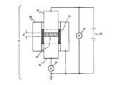
以下に本発明が適用される画像形成方法を用いた画像形成装置の一例を挙げ、これを図1に示し、本発明の構成についてさらに詳しく説明するが、これは本発明をなんら限定するものではない。 An example of an image forming apparatus using an image forming method to which the present invention is applied will be described below. This is shown in FIG. 1 and the configuration of the present invention will be described in more detail. However, this does not limit the present invention in any way. Absent.
図1は本発明に従う画像形成装置の一例の概略構成図である。 FIG. 1 is a schematic configuration diagram of an example of an image forming apparatus according to the present invention.
本例の画像形成装置は、複数の第1の像担持体1(潜像担持体)である感光ドラムを上下に並べて配置したタンデム型である。 The image forming apparatus of the present example is a tandem type in which photosensitive drums that are a plurality of first image carriers 1 (latent image carriers) are arranged side by side.
前記画像形成装置は第2の像担持体30(中間転写ベルト)を有し、前記第2の像担持体上の転写残トナーを帯電する帯電ブラシ(図上では固定帯電ブラシ)34を有する方式の電子写真カラー(多色画像)プリンターである。 The image forming apparatus has a second image carrier 30 (intermediate transfer belt) and a charging brush (fixed charging brush in the figure) 34 for charging the transfer residual toner on the second image carrier. This is an electrophotographic color (multicolor image) printer.
本例ではイエロー、マゼンタ、シアン、ブラックの四色の電子写真カラープリンターを一例として挙げているが、色、色数、色順を何ら限定するものではない。 In this example, an electrophotographic color printer of four colors of yellow, magenta, cyan, and black is given as an example, but the color, the number of colors, and the color order are not limited at all.
第1乃至第4の各画像形成部PY・PM・PC・PBkにおいて、正回転駆動された各感光ドラム1はその回転過程でそれぞれ不図示の電源回路から帯電バイアスが印加される帯電ローラー2により所定の極性及び電位に一様に一次帯電処理される。 In each of the first to fourth image forming units PY, PM, PC, and PBk, each photosensitive drum 1 that is driven to rotate forward is charged by a charging roller 2 to which a charging bias is applied from a power circuit (not shown) during the rotation process. The primary charging is uniformly performed to a predetermined polarity and potential.
前記帯電処理面に対してLEDアレイ装置3によりそれぞれフルカラー画像の色分解成分像である、イエロー、マゼンタ、シアン、ブラックの各画像パターンにしたがった光像露光LY・LM・LC・LBkを形成する露光工程を経ることで、各感光ドラム1上に画像情報の静電潜像が形成される。
Light image exposures LY, LM, LC, and LBk, which are color separation component images of full-color images, respectively according to the image patterns of yellow, magenta, cyan, and black, are formed on the charging surface by the
前記静電潜像がそれぞれ現像装置4によってトナー画像として現像される現像工程を経ることで、第1乃至第4の4つの画像形成部PY・PM・PC・PBkの各感光ドラム1の面にそれぞれ電子写真プロセスによりフルカラー画像の色分解成分像である、イエロー、マゼンタ、シアン、ブラックの色トナー画像が所定のシーケンス制御タイミングにて形成される。 The electrostatic latent image is developed on each of the photosensitive drums 1 of the first to fourth image forming portions PY, PM, PC, and PBk through a developing process in which the electrostatic latent image is developed as a toner image by the developing device 4. In each of the electrophotographic processes, color toner images of yellow, magenta, cyan, and black, which are color separation component images of a full-color image, are formed at a predetermined sequence control timing.
そして、第1乃至第4の各画像形成部PY・PM・PC・PBkにおいて、各感光ドラム1の面にイエロー、マゼンタ、シアン、ブラックの色トナー画像が形成される。 In each of the first to fourth image forming units PY, PM, PC, and PBk, yellow, magenta, cyan, and black color toner images are formed on the surface of each photosensitive drum 1.
次に、各感光ドラム1の正回転方向に順方向の矢印の時計方向に感光ドラム1と略同速で回転駆動される中間転写ベルト30の面に対して、第1乃至第4の各画像形成部PY・PM・PC・PBkの一次転写部において一次転写ローラーに不図示の電源回路から印加される一次転写バイアスによって順次に転写(一次転写)される(一次転写工程)。
Next, the first to fourth images are respectively applied to the surface of the
前記一次転写工程により、回転駆動される中間転写ベルト30の面に未定着のフルカラートナー画像(鏡像)が合成形成される。
Through the primary transfer process, an unfixed full-color toner image (mirror image) is synthesized and formed on the surface of the
また、第1乃至第4の各画像形成部PY・PM・PC・PBkにおいて、中間転写ベルト30に対するトナー画像の一次転写後に各感光ドラム1上に残った転写残トナーはブレードクリーニング装置6のクリーニングブレードによって除かれて、該装置6内の貯留部6bに貯留される(一次転写残トナークリーニング工程)。
In each of the first to fourth image forming units PY, PM, PC, and PBk, the transfer residual toner remaining on each photosensitive drum 1 after the primary transfer of the toner image to the
32は2次転写ローラー、32aは対向ローラーである。対向ローラー32aは中間転写ベルト30の下端側において中間転写ベルトの内側に配設してあり、2次転写ローラー32は対向ローラー32aとの間に中間転写ベルト30を挟ませて該中間転写ベルト30の外面に当接させて配設してある。
32 is a secondary transfer roller, and 32a is a counter roller. The
2次転写ローラー32と中間転写ベルト30との接触部が二次転写部である。
A contact portion between the secondary transfer roller 32 and the
40は画像形成装置本体の下部に配設した給紙カセットであり、最終記録媒体としての転写材Pを積載収容させてある。
所定のシーケンス制御タイミングにて搬送手段(ピックアップローラ)31を駆動させて給紙カセット40内の転写材Pを1枚分離給紙させ、所定のタイミングにて二次転写部に給送する。
The conveying means (pickup roller) 31 is driven at a predetermined sequence control timing to separate and feed one transfer material P in the
中間転写ベルト30上に合成形成された未定着のフルカラートナー画像は、この二次転写部において二次転写ローラー32に不図示の電源回路から印加される二次転写バイアスによって転写材Pの面に一括転写される二次転写工程を経ることで転写されていく。
An unfixed full-color toner image synthesized and formed on the
二次転写部を通過した転写材Pは、中間転写ベルト30の面から分離されて搬送ベルト35によって定着装置7に送られる。
The transfer material P that has passed through the secondary transfer portion is separated from the surface of the
定着装置7に送られた転写材P上の未定着のフルカラートナー画像は定着装置7により熱および圧を加えられて転写材Pに溶融固着され、シートパス41を通って画像形成装置本体の上面に配設した排紙トレイ36上にカラー画像形成物として排出される。
The unfixed full-color toner image on the transfer material P sent to the fixing device 7 is melted and fixed to the transfer material P by applying heat and pressure by the fixing device 7, passes through the
本発明において二次転写工程にて中間転写ベルト30上に残った転写残トナーは、中間転写ベルト30に当接された帯電ブラシ34により中間転写ベルト上で分散され、電荷付与される。
In the present invention, the untransferred toner remaining on the
前記帯電ブラシは回転ブラシであっても固定ブラシであってもよい。 The charging brush may be a rotating brush or a fixed brush.
本発明で使用される帯電ブラシの毛の密度は1.0×10⁷乃至1.0×10⁹(本/m2)であって、前記帯電ブラシのブラシ一本の平均直径I(μm)は10乃至70(μm)である。 The density of the bristle of the charging brush used in the present invention is 1.0 × 10 7 to 1.0 × 10 9 (lines / m 2 ), and the average diameter I (μm) of one brush of the charging brush. Is 10 to 70 (μm).
本発明におけるブラシの体積抵抗値は1.0×10⁴乃至1.0×10¹⁰Ω・cmであることがトナーに対して好ましい電荷を付与できるため好ましい。 The volume resistance value of the brush in the present invention is preferably 1.0 × 10 4 to 1.0 × 10 10 Ω · cm because a preferable charge can be imparted to the toner.
帯電ブラシの素材としては何ら限定する物ではないが、レーヨン、アクリル、ポリエステル等の繊維にカーボンや金属粉を含ませて抵抗値を制御したものが一例として挙げられる。 The material of the charging brush is not limited in any way, but examples thereof include those in which the resistance value is controlled by adding carbon or metal powder to fibers such as rayon, acrylic, and polyester.
また、帯電ローラー33を併用することでトナーに更に電荷を付与できる点で好ましい。
Further, it is preferable to use the charging
転写残トナーを良好に帯電させるために帯電ブラシと帯電ローラーから転写残トナーにバイアスを印加することが可能である。 In order to satisfactorily charge the transfer residual toner, it is possible to apply a bias to the transfer residual toner from the charging brush and the charging roller.
印加するバイアスは500乃至2500Vであることが好ましい。 The bias to be applied is preferably 500 to 2500V.
そして、帯電された転写残トナーは中間転写ベルト30から任意の一次転写ローラー5に不図示の電源回路から印加される一次転写バイアスによって任意のドラムへと転写される。
The charged transfer residual toner is transferred to an arbitrary drum from the
その後、前記トナーはブレードクリーニング装置6のクリーニングブレード6aによって除かれ、画像形成部中の廃トナーボックス6に送られて貯留される。
Thereafter, the toner is removed by the cleaning blade 6a of the
また、前記二次転写残トナークリーニング工程を行う画像形成部は適宜変更されることがより好ましい。 More preferably, the image forming unit that performs the secondary transfer residual toner cleaning step is appropriately changed.
それによって、それぞれの画像形成部中の廃トナーボックス6に偏ることなく廃トナーが回収されるため、更なる装置の小型化が可能となる(二次転写残トナークリーニング工程)。
As a result, the waste toner is collected without being biased to the
前記のような二次転写残トナークリーニング工程を有することにより、中間転写ベルトをクリーニングするクリーニングブレードや廃トナー回収ボックス等の部材を減らすことで更なる装置の小型化が可能となる。 By having the secondary transfer residual toner cleaning step as described above, it is possible to further reduce the size of the apparatus by reducing members such as a cleaning blade and a waste toner collection box for cleaning the intermediate transfer belt.
また、帯電ローラーでの転写残トナーの帯電と比較して、帯電ブラシでは転写残トナーを分散することでトナーを効率よく帯電させ、ドラムへの転写を良化するとともに、ドラム上でのクリーニングブレードによる回収の負荷を減らすことが期待できる。 Compared to charging the transfer residual toner with the charging roller, the charging brush disperses the transfer residual toner to charge the toner efficiently, improving the transfer to the drum, and cleaning drum on the drum. It can be expected to reduce the recovery load due to.
しかし、帯電ブラシという特殊な構造の部材を用いるため、極低温低湿度環境において長期にわたって印刷する際には転写残トナーがブラシに滞留したり、ブラシが汚染されたりするという問題が起こりやすい傾向にあった。 However, since a member with a special structure called a charging brush is used, there is a tendency that untransferred toner remains on the brush or the brush is contaminated when printing over a long period of time in an extremely low temperature and low humidity environment. there were.
そのため、低温低湿環境下において長期にわたって印刷をしていくと、帯電ブラシによって充分かつ均一な電荷を転写残トナーに与えることができなくなり、クリーニング不良を引き起こしやすい傾向がある。 For this reason, when printing is performed for a long time in a low-temperature and low-humidity environment, it becomes impossible to give a sufficient and uniform charge to the transfer residual toner by the charging brush, which tends to cause cleaning failure.
本発明者らは鋭意検討の結果、微細な脂肪酸金属塩をトナー粒子に適度な遊離率となるように外添させたトナーを用いることによって前記問題を解決できることを見出した。 As a result of intensive studies, the present inventors have found that the above problem can be solved by using a toner in which a fine fatty acid metal salt is externally added to toner particles so as to have an appropriate release rate.
具体的には、少なくとも脂肪酸金属塩をトナー粒子100.00質量部に対して0.05乃至0.50質量部外添させたトナーであり、前記脂肪酸金属塩のトナーに対する遊離率が1.0%以上25.0%以下であり、前記脂肪酸金属塩の体積基準のメジアン径(D50)をD50s(μm)としたとき、
0.15≦D50s≦1.00
の関係を満たすトナーを用いることで前記問題が解決される。
Specifically, it is a toner in which at least 0.05 to 0.50 parts by mass of a fatty acid metal salt is externally added to 100.00 parts by mass of toner particles, and the liberation ratio of the fatty acid metal salt to the toner is 1.0. % To 25.0%, when the volume-based median diameter (D50) of the fatty acid metal salt is D50s (μm),
0.15 ≦ D50s ≦ 1.00
The above problem is solved by using a toner satisfying the above relationship.
具体的なメカニズムについては明らかになっていないが、本発明のトナーは脂肪酸金属塩が外添されることによって、トナー同士、および帯電ブラシに対する潤滑性が向上すると考えられる。 Although the specific mechanism is not clear, it is considered that the toner of the present invention is improved in lubricity between the toner and the charging brush by the external addition of the fatty acid metal salt.
そのため、極低温低湿環境であっても転写残トナーがブラシ中に滞留しにくくなり、ブラシによって中間転写体上の転写残トナーを効率よく分散し、電荷を付与する効果が得られやすく、結果として高いクリーニング性を得ることが可能であると予測している。 Therefore, even in an extremely low temperature and low humidity environment, the transfer residual toner is less likely to stay in the brush, and it is easy to obtain an effect of efficiently dispersing the transfer residual toner on the intermediate transfer member and imparting an electric charge. It is predicted that high cleaning properties can be obtained.
また、脂肪酸金属塩が従来よりも小粒径であり、トナー粒子に均一に外添されやすく、遊離しにくいため、脂肪酸金属塩の遊離によるブラシ汚染が引き起こりにくい傾向にあり、高いクリーニング性を維持することが可能であると考えている。 In addition, since fatty acid metal salts have a smaller particle size than conventional ones and are easily externally added to toner particles and are not easily released, brush contamination due to the release of fatty acid metal salts tends not to occur, resulting in high cleaning properties. I think it is possible to maintain.
更には適度な遊離率を有する微細な脂肪酸金属塩であるため、ブラシとの摩擦による脂肪酸金属塩の遊離によるブラシ汚染が抑制されることで長期にわたって転写残トナーを帯電させることが可能であると推測している。 Furthermore, since it is a fine fatty acid metal salt having an appropriate release rate, it is possible to charge the transfer residual toner over a long period of time by suppressing brush contamination due to the release of the fatty acid metal salt due to friction with the brush. I guess.
一方で、適度な微細脂肪酸金属塩の遊離によるブラシ自体の潤滑性の向上により、トナーをブラシ中に滞留させにくくなり、長期にわたり転写残トナーを良好に帯電させることが可能であると推測している。 On the other hand, the improvement in lubricity of the brush itself due to the release of moderate fine fatty acid metal salt makes it difficult for the toner to stay in the brush, and it is assumed that the transfer residual toner can be charged well over a long period of time. Yes.
本発明のトナーには脂肪酸金属塩がトナー粒子100.00質量部に対して0.05乃至0.50質量部外添されていることが好ましく、より好ましくは0.10乃至0.30質量部である。 In the toner of the present invention, a fatty acid metal salt is preferably added in an amount of 0.05 to 0.50 parts by mass with respect to 100.00 parts by mass of toner particles, and more preferably 0.10 to 0.30 parts by mass. It is.
添加部数が0.05よりも小さいときは脂肪酸金属塩添加による効果が小さくなる傾向にあり、トナーのブラシ中での滞留が起こりやすい傾向にある。 When the number of added parts is less than 0.05, the effect of adding the fatty acid metal salt tends to be small, and the toner tends to stay in the brush.
また、0.50よりも大きいときは脂肪酸金属塩の遊離が起こりやすくなり、脂肪酸金属塩による帯電ブラシ汚染から転写残トナーに均一に帯電させ難くなり、クリーニング不良が起こりやすい傾向にある。 On the other hand, when the ratio is larger than 0.50, the fatty acid metal salt is likely to be liberated, and it becomes difficult to uniformly charge the transfer residual toner due to the contamination of the charging brush by the fatty acid metal salt, which tends to cause poor cleaning.
前記脂肪酸金属塩のトナーに対する遊離率は1.0%以上25.0%以下であることが好ましく、更に好ましい遊離率は2.0%以上20.0%以下である。 The liberation rate of the fatty acid metal salt with respect to the toner is preferably 1.0% or more and 25.0% or less, and more preferably 2.0% or more and 20.0% or less.
遊離率が1.0%よりも小さいときは微細な脂肪酸金属塩の適度な遊離によるブラシの潤滑性を維持し難くなり、トナーがブラシ中に滞留し易くなり、結果として中間転写体上の転写残トナーに充分な帯電を付与することが困難になる傾向がある。 When the liberation rate is less than 1.0%, it becomes difficult to maintain the lubricity of the brush due to moderate liberation of fine fatty acid metal salts, and the toner tends to stay in the brush, resulting in transfer on the intermediate transfer member. It tends to be difficult to impart sufficient charge to the remaining toner.
一方で、遊離率が25.0%よりも大きいと脂肪酸金属塩の遊離による部材汚染が進行し易い傾向にある。 On the other hand, if the liberation rate is larger than 25.0%, member contamination due to liberation of the fatty acid metal salt tends to proceed.
また、脂肪酸金属塩の遊離により長期にわたる印刷の場合、脂肪酸金属塩の遊離により脂肪酸金属塩による潤滑効果が小さくなり、トナーが帯電ブラシ中に滞留しやすくなる傾向にある。 Further, in the case of printing for a long time due to liberation of the fatty acid metal salt, the lubrication effect by the fatty acid metal salt is reduced due to the liberation of the fatty acid metal salt, and the toner tends to stay in the charging brush.
本発明におけるトナー中の脂肪酸金属塩の遊離率は以下のようにして算出した。 The liberation rate of the fatty acid metal salt in the toner in the present invention was calculated as follows.
デジタル振動計(デジバイブロ MODEL 1332)を有するパウダーテスター(細川ミクロン社製)を用いた篩前後の脂肪酸金属塩量を、蛍光X線分析装置 Axios(PANalytical製)及び測定条件設定及び測定データ解析をするための付属の専用ソフト「SuperQ ver.4.0F」(PANalytical社製)を用いて求め、脂肪酸金属塩の遊離率を求めた。 Using a powder tester (manufactured by Hosokawa Micron Corporation) having a digital vibrometer (Digivibro MODEL 1332), the amount of fatty acid metal salt before and after the sieve is measured with a fluorescent X-ray analyzer Axios (manufactured by PANallytical), measurement condition setting and measurement data analysis The amount of fatty acid metal salt liberation was determined using the attached dedicated software “SuperQ ver. 4.0F” (manufactured by PANalytical).
具体的な測定法としては、パウダーテスターの振動台に目開き25μm(635メッシュ)篩をセットする。この目開き25μm(635メッシュ)篩上に正確に秤量した試料5gを加え、デジタル振動計の振幅が約0.60mmになるように調整し、約2分間振動を加える。前記作業を更に2回繰り返し、試料を25μm(635メッシュ)篩に計3回とおす。次に、得られた試料を直径40mmのアルミリングに約4g載せ、プレス機にて150kNで圧縮しサンプルを作成する。得られたサンプルを蛍光X線分析装置(Axios)で測定した。尚、X線管球のアノードとしてはRhを用い、測定雰囲気は真空、測定径(コリメーターマスク径)は27mm、測定時間10秒とする。また、軽元素を測定する場合にはプロポーショナルカウンタ(PC)、重元素を測定する場合にはシンチレーションカウンタ(SC)で検出する。 As a specific measuring method, a sieve having a mesh size of 25 μm (635 mesh) is set on a vibrating table of a powder tester. 5 g of a sample accurately weighed is added to the sieve having a mesh size of 25 μm (635 mesh), the amplitude of the digital vibrometer is adjusted to about 0.60 mm, and vibration is applied for about 2 minutes. The above operation is repeated two more times, and the sample is passed through a 25 μm (635 mesh) sieve a total of three times. Next, about 4 g of the obtained sample is placed on an aluminum ring having a diameter of 40 mm, and compressed by a press machine at 150 kN to prepare a sample. The obtained sample was measured with a fluorescent X-ray analyzer (Axios). Rh is used as the anode of the X-ray tube, the measurement atmosphere is vacuum, the measurement diameter (collimator mask diameter) is 27 mm, and the measurement time is 10 seconds. Further, when measuring a light element, it is detected by a proportional counter (PC), and when measuring a heavy element, it is detected by a scintillation counter (SC).
脂肪酸金属塩の遊離率は、篩前後の脂肪酸金属塩の金属元素のKα線ネット強度(KCPS)を測定して、下記式より求めた。
{(篩前のトナーにおける脂肪酸金属塩の金属元素のKα線ネット強度)−(篩を通過したトナーにおける脂肪酸金属塩の金属元素のKα線ネット強度)}/(篩前のトナーにおける脂肪酸金属塩の金属元素のKα線ネット強度)
The liberation rate of the fatty acid metal salt was determined from the following formula by measuring the Kα ray net intensity (KCPS) of the metal element of the fatty acid metal salt before and after the sieve.
{(Kα ray net intensity of metal element of fatty acid metal salt in toner before sieve) − (Kα ray net intensity of metal element of fatty acid metal salt in toner passed through sieve)} / (Fatty acid metal salt in toner before sieve) (Kα line net intensity of metallic elements)
前記脂肪酸金属塩の体積基準のメジアン径D50s(μm)は、0.15≦D50s≦1.00であることが好ましく、更に好ましくは0.15≦D50s≦0.75であり、更に好ましくは0.15≦D50s≦0.60である。 The volume-based median diameter D50s (μm) of the fatty acid metal salt is preferably 0.15 ≦ D50s ≦ 1.00, more preferably 0.15 ≦ D50s ≦ 0.75, and still more preferably 0. .15 ≦ D50s ≦ 0.60.
D50sが0.15よりも小さいと脂肪酸金属塩添加の充分な効果を得がたくなる傾向にある。 When D50s is smaller than 0.15, it tends to be difficult to obtain a sufficient effect of adding a fatty acid metal salt.
また、1.00よりも大きいとトナー粒子との静電的付着力が小さくなるため脂肪酸金属塩が遊離されやすくなり、部材汚染、および、トナーのブラシ中の滞留が起こりやすい傾向にある。 On the other hand, when the value is larger than 1.00, the electrostatic adhesion force with the toner particles becomes small, so that the fatty acid metal salt tends to be liberated, and the member tends to be contaminated and the toner stays in the brush.
本発明で用いられる脂肪酸金属塩の体積基準のメジアン径D50s、スパン値Aの測定は、JIS Z8825−1(2001年)に準じて測定されるが、具体的には以下の通りである。 The volume-based median diameter D50s and span value A of the fatty acid metal salt used in the present invention are measured in accordance with JIS Z8825-2 (2001), and are specifically as follows.
測定装置としては、レーザー回折・散乱式粒度分布測定装置「LA−920」(堀場製作所社製)を用いる。測定条件の設定および測定データの解析は、LA−920に付属の専用ソフト「HORIBA LA−920 for Windows(登録商標) WET(LA−920) Ver.2.02」を用いる。また、測定溶媒としては、予め不純固形物などを除去したイオン交換水を用いる。 As a measuring device, a laser diffraction / scattering particle size distribution measuring device “LA-920” (manufactured by Horiba, Ltd.) is used. The dedicated software “HORIBA LA-920 for Windows (registered trademark) WET (LA-920) Ver. 2.02” attached to LA-920 is used for setting measurement conditions and analyzing measurement data. As the measurement solvent, ion-exchanged water from which impure solids are removed in advance is used.
測定手順は、以下の通りである。
(1)バッチ式セルホルダーをLA−920に取り付ける。
(2)所定量のイオン交換水をバッチ式セルに入れ、バッチ式セルをバッチ式セルホルダーにセットする。
(3)専用のスターラーチップを用いて、バッチ式セル内を撹拌する。
(4)「表示条件設定」画面の「屈折率」ボタンを押し、ファイル「110A000I」(相対屈折率1.10)を選択する。
(5)「表示条件設定」画面において、粒子径基準を体積基準とする。
(6)1時間以上の暖気運転を行った後、光軸の調整、光軸の微調整、ブランク測定を行う。
(7)ガラス製の100ml平底ビーカーに約60mlのイオン交換水を入れる。この中に分散剤として、「コンタミノンN」(非イオン界面活性剤、陰イオン界面活性剤、有機ビルダーからなるpH7の精密測定器洗浄用中性洗剤の10質量%水溶液、和光純薬工業社製)をイオン交換水で約3質量倍に希釈した希釈液を約0.3ml加える。
(8)発振周波数50kHzの発振器2個を、位相を180度ずらした状態で内蔵し、電気的出力120Wの超音波分散器「Ultrasonic Dispension System Tetora150」(日科機バイオス社製)を準備する。超音波分散器の水槽内に約3.3lのイオン交換水を入れ、この水槽中にコンタミノンNを約2ml添加する。
(9)前記(7)のビーカーを前記超音波分散器のビーカー固定穴にセットし、超音波分散器を作動させる。そして、ビーカー内の水溶液の液面の共振状態が最大となるようにビーカーの高さ位置を調整する。
(10)前記(9)のビーカー内の水溶液に超音波を照射した状態で、約1mgの脂肪酸金属塩を少量ずつ前記ビーカー内の水溶液に添加し、分散させる。そして、さらに60秒間超音波分散処理を継続する。尚、この際に脂肪酸金属塩が固まりとなって液面に浮く場合があるが、その場合はビーカーを揺り動かすことで固まりを水中に沈めてから60秒間の超音波分散を行う。また、超音波分散にあたっては、水槽の水温が10℃以上40℃以下となる様に適宜調節する。
(11)前記(10)で調製した脂肪酸金属塩が分散した水溶液を、気泡が入らないように注意しながら直ちにバッチ式セルに少量ずつ添加して、タングステンランプの透過率が90%〜95%となるように調整する。そして、粒度分布の測定を行う。得られた体積基準の粒度分布のデータを元に、メジアン径(D50)、5%積算径(D5s)および95%積算径(D95s)を求め、下記(1)式からスパン値Aを算出する。
スパン値A=(D95s−D5s)/D50s (1)式
The measurement procedure is as follows.
(1) A batch type cell holder is attached to LA-920.
(2) A predetermined amount of ion-exchanged water is put into a batch type cell, and the batch type cell is set in a batch type cell holder.
(3) The inside of the batch cell is stirred using a dedicated stirrer chip.
(4) Press the “refractive index” button on the “display condition setting” screen and select the file “110A000I” (relative refractive index 1.10).
(5) In the “display condition setting” screen, the particle diameter reference is set as the volume reference.
(6) After performing warm-up operation for 1 hour or more, optical axis adjustment, optical axis fine adjustment, and blank measurement are performed.
(7) Put about 60 ml of ion-exchanged water in a glass 100 ml flat bottom beaker. Among them, as a dispersant, “Contaminone N” (a nonionic surfactant, an anionic surfactant, a 10% by weight aqueous solution of a neutral detergent for washing a pH 7 precision measuring instrument comprising an organic builder, Wako Pure Chemical Industries, Ltd. About 0.3 ml of a diluted solution obtained by diluting the product (manufactured) with ion exchange water about 3 times by mass is added.
(8) Two oscillators with an oscillation frequency of 50 kHz are incorporated with the phase shifted by 180 degrees, and an ultrasonic disperser “Ultrasonic Dissipation System Tetora 150” (manufactured by Nikki Bios Co., Ltd.) having an electrical output of 120 W is prepared. About 3.3 l of ion-exchanged water is placed in the water tank of the ultrasonic disperser, and about 2 ml of Contaminone N is added to the water tank.
(9) The beaker of (7) is set in the beaker fixing hole of the ultrasonic disperser, and the ultrasonic disperser is operated. And the height position of a beaker is adjusted so that the resonance state of the liquid level of the aqueous solution in a beaker may become the maximum.
(10) In a state where the aqueous solution in the beaker of (9) is irradiated with ultrasonic waves, about 1 mg of a fatty acid metal salt is added to the aqueous solution in the beaker little by little and dispersed. Then, the ultrasonic dispersion process is continued for another 60 seconds. In this case, the fatty acid metal salt may solidify and float on the liquid surface. In that case, ultrasonic dispersion is performed for 60 seconds after the mass is submerged by shaking the beaker. Moreover, in ultrasonic dispersion, it adjusts suitably so that the water temperature of a water tank may become 10 to 40 degreeC.
(11) The aqueous solution in which the fatty acid metal salt prepared in the above (10) is dispersed is immediately added little by little to a batch type cell, taking care not to enter bubbles, and the transmittance of the tungsten lamp is 90% to 95%. Adjust so that Then, the particle size distribution is measured. Based on the obtained volume-based particle size distribution data, the median diameter (D50), 5% integrated diameter (D5s), and 95% integrated diameter (D95s) are obtained, and the span value A is calculated from the following equation (1). .
Span value A = (D95s−D5s) / D50s (1) Formula
前記脂肪酸金属塩のスパン値Aは1.75以下であることが好ましく、より好ましくは1.00以下である。 The span value A of the fatty acid metal salt is preferably 1.75 or less, more preferably 1.00 or less.
スパン値Aが1.75よりも大きいときは脂肪酸金属塩の粒径にばらつきが生じるため、転写残トナーに与える帯電にばらつきが生じる傾向がある。 When the span value A is larger than 1.75, the particle size of the fatty acid metal salt varies, and therefore, there is a tendency that the charge applied to the untransferred toner varies.
また、粒径のばらつきから結果的にトナーの凝集性を高めることになり、トナーのブラシ中の滞留を引き起こしやすくなる。前記トナーの体積基準のメジアン径D50t(μm)は4.0≦D50t≦9.0であることが好ましく、更に好ましくは4.0≦D50t≦7.0である。 In addition, the cohesion of the toner is increased as a result of the variation in the particle diameter, and the toner tends to stay in the brush. The volume-based median diameter D50t (μm) of the toner is preferably 4.0 ≦ D50t ≦ 9.0, and more preferably 4.0 ≦ D50t ≦ 7.0.
D50tが4.0よりも小さいとトナー自体がブラシに溜め込まれやすくなり、クリーニング性能が悪化しやすくなり、9.0よりも大きいときは細線再現性が悪くなるなど、近年の高画質化要求を満たさなくなる傾向にある。 When D50t is smaller than 4.0, the toner itself is likely to be stored in the brush, and the cleaning performance tends to be deteriorated. When it is larger than 9.0, the fine line reproducibility is deteriorated. There is a tendency not to satisfy.
前記トナーは、フロー式粒子像分析装置で測定される該トナーの平均円形度が0.960乃至0.995であることがトナーに掛かる機械的負荷を低下させることで潤滑に摩擦帯電でき、粒子が均一に帯電しやすい点で好ましい。 When the toner has an average circularity of 0.960 to 0.995 as measured by a flow particle image analyzer, the toner can be triboelectrically charged by lubrication by reducing the mechanical load applied to the toner. Is preferable in that it is easily charged uniformly.
また、0.960よりも小さい場合、添加された脂肪酸金属塩がトナー表面の凹部分に存在し、粒子中に帯電分布が発生しやすくなり、転写残トナーを均一に帯電付与し難くなる傾向にある。 On the other hand, if it is less than 0.960, the added fatty acid metal salt is present in the concave portion of the toner surface, and the charge distribution tends to occur in the particles, so that it is difficult to uniformly charge the transfer residual toner. is there.
また、本発明のトナー粒子の電界強度5×10³V/cmにおける体積抵抗値は1.0×1013乃至1.0×1017Ω・cmであることが、ブラシとの摩擦帯電により適切な帯電をしやすい点で好ましい。 The toner particles of the present invention have a volume resistance value of 1.0 × 10 13 to 1.0 × 10 17 Ω · cm at an electric field strength of 5 × 10 3 V / cm, which is appropriate due to frictional charging with the brush. It is preferable in that it can be easily charged.
本発明のトナー粒子は、トナーの製造方法は特性を達成可能なものであれば特に限定することがなく、公知の製造方法が使用可能である。 The toner particles of the present invention are not particularly limited as long as the toner production method can achieve the characteristics, and a known production method can be used.
公知の製造方法の中でも本発明のトナー粒子は、少なくとも重合性単量体、着色剤、極性樹脂、離型剤及び重合開始剤を含有する重合性単量体組成物を水系媒体中に分散して造粒し、重合性単量体を重合させることにより生成されたトナー粒子であることが好ましい。 Among the known production methods, the toner particles of the present invention are obtained by dispersing a polymerizable monomer composition containing at least a polymerizable monomer, a colorant, a polar resin, a release agent and a polymerization initiator in an aqueous medium. The toner particles are preferably produced by granulating and polymerizing a polymerizable monomer.
前記造粒方式で合成されたトナー粒子は粒度分布がシャープで、円形度の高いトナーを得やすく、トナーの流動性を高くし、摩擦帯電を引き起こし優れた帯電性能を得やすい傾向にある。 The toner particles synthesized by the granulation method have a sharp particle size distribution and are easy to obtain a toner having a high degree of circularity, tend to increase the fluidity of the toner, cause tribocharging, and easily obtain excellent charging performance.
以下、本発明に用いられるトナー粒子を得る上で最も好適な懸濁重合法を例示して、該トナー粒子の製造方法を説明する。 Hereinafter, the most suitable suspension polymerization method for obtaining the toner particles used in the present invention will be exemplified and the production method of the toner particles will be described.
重合性単量体、着色剤、極性樹脂、離型剤及び必要に応じた他の添加物を、ホモジナイザー、ボールミル、コロイドミル、超音波分散機の如き分散機に依って均一に溶解または分散させ、これに重合開始剤を溶解し、重合性単量体組成物を調製する。 Dissolve or disperse the polymerizable monomer, colorant, polar resin, release agent and other additives as required uniformly using a disperser such as a homogenizer, ball mill, colloid mill, or ultrasonic disperser. In this, a polymerization initiator is dissolved to prepare a polymerizable monomer composition.
次に、該重合性単量体組成物を分散安定剤含有の水系媒体中に分散して造粒して粒子を形成し、粒子中の重合性単量体を重合させることによってトナー粒子を製造する。 Next, the polymerizable monomer composition is dispersed in an aqueous medium containing a dispersion stabilizer and granulated to form particles, and toner particles are produced by polymerizing the polymerizable monomer in the particles. To do.
前記重合開始剤は、重合性単量体中に他の添加剤を添加する時に同時に加えても良いし、水系媒体中に該重合性単量体組成物を分散する直前に混合しても良い。 The polymerization initiator may be added at the same time when other additives are added to the polymerizable monomer, or may be mixed immediately before the polymerizable monomer composition is dispersed in the aqueous medium. .
また、造粒直後、重合反応を開始する前に重合性単量体あるいは溶媒に溶解した重合開始剤を加えることもできる。 Also, a polymerization initiator dissolved in a polymerizable monomer or solvent can be added immediately after granulation and before starting the polymerization reaction.
本発明において、分散時、造粒時、重合反応を開始する前に、pH調整のため適当な酸を添加することが好ましい。 In the present invention, it is preferable to add an appropriate acid for pH adjustment at the time of dispersion, granulation, and before starting the polymerization reaction.
本発明のトナーに用いられる酸としては、一般的に用いられている塩酸、硫酸、硝酸などの酸を用いることができる。 As the acid used in the toner of the present invention, commonly used acids such as hydrochloric acid, sulfuric acid, and nitric acid can be used.
重合時の水溶液を適当なpHに調整することによって、より均一な帯電性能を有するトナーを得ることが可能である。 By adjusting the aqueous solution during polymerization to an appropriate pH, it is possible to obtain a toner having more uniform charging performance.
該重合性単量体組成物の分散工程から重合工程に至る重合反応時に極性樹脂を添加すると、トナー粒子となる重合性単量体組成物と水系分散媒体の呈する極性のバランスに応じて、極性樹脂の存在状態を制御することができる。 When a polar resin is added during the polymerization reaction from the dispersion step of the polymerizable monomer composition to the polymerization step, the polarity varies depending on the balance between the polarity of the polymerizable monomer composition to be toner particles and the aqueous dispersion medium. The presence state of the resin can be controlled.
即ち、極性樹脂を添加することで、樹脂層に応じた機能分離が可能となる。また、懸濁重合法により得られるトナー粒子は、離型剤成分を内包化しているコアシェル構造を有しているため好ましい。 That is, by adding a polar resin, functional separation according to the resin layer is possible. Further, the toner particles obtained by the suspension polymerization method are preferable because they have a core-shell structure including a release agent component.
極性樹脂としては、ポリエステル樹脂、エポキシ樹脂、スチレン−アクリル酸共重合体、スチレン−メタクリル酸共重合体、スチレン−マレイン酸共重合体が挙げられる。 Examples of the polar resin include polyester resin, epoxy resin, styrene-acrylic acid copolymer, styrene-methacrylic acid copolymer, and styrene-maleic acid copolymer.
特にポリエステル樹脂が好ましく、酸価は4乃至20mgKOH/gの範囲が好ましい。酸価が4mgKOH/gより小さい場合、シェル構造を形成しにくく、かつ帯電の立ち上がりが遅く、画像濃度の低下やカブリといった弊害を引き起こしやすい。 A polyester resin is particularly preferable, and the acid value is preferably in the range of 4 to 20 mgKOH / g. When the acid value is less than 4 mgKOH / g, it is difficult to form a shell structure, and the rise of charging is slow, which tends to cause problems such as a decrease in image density and fogging.
酸価が20mgKOH/gを超える場合、帯電性に影響を及ぼし現像性が悪化し易くなる。また分子量は3,000乃至30,000にメインピークの分子量を有すると、トナー粒子の流動性、負摩擦帯電特性を良好にすることができるため好ましい。 When the acid value exceeds 20 mgKOH / g, the chargeability is affected and the developability tends to deteriorate. The molecular weight of 3,000 to 30,000 is preferably a main peak molecular weight because the fluidity and negative frictional charging characteristics of the toner particles can be improved.
前記極性樹脂の好ましい添加量は、結着樹脂を構成する重合性単量体100質量部に対して1乃至25質量部であり、より好ましくは2乃至15質量部である。 A preferable addition amount of the polar resin is 1 to 25 parts by mass, and more preferably 2 to 15 parts by mass with respect to 100 parts by mass of the polymerizable monomer constituting the binder resin.
1質量部未満ではトナー粒子中での極性樹脂の存在状態が不均一となりやすく、一方、25質量部を超えるとトナー粒子の表面に形成される極性樹脂の層が厚くなるために、好ましくない。 If the amount is less than 1 part by mass, the presence state of the polar resin in the toner particles tends to be non-uniform. On the other hand, if it exceeds 25 parts by mass, the layer of the polar resin formed on the surface of the toner particles becomes thick.
本発明のトナーに用いられる結着樹脂を構成する重合性単量体としては、一般的に用いられているスチレン−アクリル共重合体、スチレン−メタクリル共重合体、エポキシ樹脂、スチレン−ブタジエン共重合体が挙げられる。 As the polymerizable monomer constituting the binder resin used in the toner of the present invention, generally used styrene-acrylic copolymer, styrene-methacrylic copolymer, epoxy resin, styrene-butadiene copolymer Coalescence is mentioned.
前記結着樹脂を構成する重合性単量体としては、ラジカル重合が可能なビニル系重合性単量体を用いることが可能である。該ビニル系重合性単量体としては、単官能性重合性単量体或いは多官能性重合性単量体を使用することができる。 As the polymerizable monomer constituting the binder resin, a vinyl polymerizable monomer capable of radical polymerization can be used. As the vinyl polymerizable monomer, a monofunctional polymerizable monomer or a polyfunctional polymerizable monomer can be used.
結着樹脂を構成するための重合性単量体としては、以下のものが挙げられる。スチレン;o−(m−,p−)メチルスチレン、m−(p−)エチルスチレンの如きスチレン系単量体;アクリル酸メチル、メタクリル酸メチル、アクリル酸エチル、メタクリル酸エチル、アクリル酸プロピル、メタクリル酸プロピル、アクリル酸ブチル、メタクリル酸ブチル、アクリル酸オクチル、メタクリル酸オクチル、アクリル酸ドデシル、メタクリル酸ドデシル、アクリル酸ステアリル、メタクリル酸ステアリル、アクリル酸ベヘニル、メタクリル酸ベヘニル、アクリル酸2−エチルヘキシル、メタクリル酸2−エチルヘキシル、アクリル酸ジメチルアミノエチル、メタクリル酸ジメチルアミノエチル、アクリル酸ジエチルアミノエチル、メタクリル酸ジエチルアミノエチルの如きアクリル酸エステル系単量体或いはメタクリル酸エステル系単量体;ブタジエン、イソプレン、シクロヘキセン、アクリロニトリル、メタクリロニトリル、アクリル酸アミド、メタクリル酸アミドの如きエン系単量体。 Examples of the polymerizable monomer for constituting the binder resin include the following. Styrene; Styrenic monomers such as o- (m-, p-) methylstyrene, m- (p-) ethylstyrene; methyl acrylate, methyl methacrylate, ethyl acrylate, ethyl methacrylate, propyl acrylate, Propyl methacrylate, butyl acrylate, butyl methacrylate, octyl acrylate, octyl methacrylate, dodecyl acrylate, dodecyl methacrylate, stearyl acrylate, stearyl methacrylate, behenyl acrylate, behenyl methacrylate, 2-ethylhexyl acrylate, Acrylic acid ester monomers such as 2-ethylhexyl methacrylate, dimethylaminoethyl acrylate, dimethylaminoethyl methacrylate, diethylaminoethyl acrylate and diethylaminoethyl methacrylate, Ether-based monomers; butadiene, isoprene, cyclohexene, acrylonitrile, methacrylonitrile, acrylic acid amide, such as ene-based monomers methacrylamide.
これらの重合性単量体は、単独、または、一般的には出版物ポリマーハンドブック第2版III−p139乃至192(John Wiley&Sons社製)に記載の理論ガラス転移点(Tg)が、40℃乃至75℃を示すように重合性単量体を適宜混合して用いられる。 These polymerizable monomers are used alone or in general, and have a theoretical glass transition point (Tg) described in publication polymer handbook 2nd edition III-p139 to 192 (John Wiley & Sons) of 40 ° C. to A polymerizable monomer is appropriately mixed and used so as to exhibit 75 ° C.
理論ガラス転移点が40℃未満の場合にはトナーの耐久安定性の面から問題が生じやすく、一方75℃を超える場合は、低温定着時の光沢度が低下する。 When the theoretical glass transition point is less than 40 ° C., a problem is likely to occur from the viewpoint of the durability stability of the toner, whereas when it exceeds 75 ° C., the glossiness at low temperature fixing is lowered.
本発明においては、トナーのTHF可溶分を好ましい分子量分布とし、低温定着性能を向上するために、低分子量ポリマーを添加することが可能である。 In the present invention, it is possible to add a low molecular weight polymer in order to make the THF soluble content of the toner have a preferable molecular weight distribution and improve the low-temperature fixing performance.
低分子量ポリマーは、懸濁重合法によってトナー粒子を製造する場合には、重合性単量体組成物中に添加することができる。 The low molecular weight polymer can be added to the polymerizable monomer composition when toner particles are produced by suspension polymerization.
前記低分子量ポリマーとしては、ゲルパーミエーションクロマトグラフィー(GPC)により測定される重量平均分子量(Mw)が2,000乃至5,000の範囲で、且つ、Mw/Mnが4.5未満、好ましくは3.0未満のものが定着性と現像性において好ましい。 The low molecular weight polymer has a weight average molecular weight (Mw) measured by gel permeation chromatography (GPC) in the range of 2,000 to 5,000, and Mw / Mn is less than 4.5, preferably Those of less than 3.0 are preferred in terms of fixability and developability.
低分子量ポリマーの一例としては、以下のものが挙げられる。ポリスチレン、ポリビニルトルエンの如きスチレン及びその置換体の単重合体;スチレン−プロピレン共重合体、スチレン−ビニルトルエン共重合体、スチレン−ビニルナフタリン共重合体、スチレン−アクリル酸メチル共重合体、スチレン−アクリル酸エチル共重合体、スチレン−アクリル酸ブチル共重合体、スチレン−アクリル酸オクチル共重合体、スチレン−アクリル酸ジメチルアミノエチル共重合体、スチレン−メタクリル酸メチル共重合体、スチレン−メタクリル酸エチル共重合体、スチレン−メタクリル酸ブチル共重合体、スチレン−メタクリ酸ジメチルアミノエチル共重合体、スチレン−ビニルメチルエーテル共重合体、スチレン−ビニルエチルエーテル共重合体、スチレン−ビニルメチルケトン共重合体、スチレン−ブタジエン共重合体、スチレン−イソプレン共重合体、スチレン−マレイン酸共重合体、スチレン−マレイン酸エステル共重合体の如きスチレン系共重合体;ポリメチルメタクリレート、ポリブチルメタクリレート、ポリ酢酸ビニル、ポリエチレン、ポリプロピレン、ポリビニルブチラール、シリコーン樹脂、ポリエステル樹脂、ポリアミド樹脂、エポキシ樹脂、ポリアクリル樹脂、ロジン、変性ロジン、テルペン樹脂、フェノール樹脂、脂肪族または脂環族炭化水素樹脂、芳香族系石油樹脂。 Examples of low molecular weight polymers include: Homopolymers of styrene such as polystyrene and polyvinyltoluene and substituted products thereof; styrene-propylene copolymer, styrene-vinyltoluene copolymer, styrene-vinylnaphthalene copolymer, styrene-methyl acrylate copolymer, styrene- Ethyl acrylate copolymer, styrene-butyl acrylate copolymer, styrene-octyl acrylate copolymer, styrene-dimethylaminoethyl acrylate copolymer, styrene-methyl methacrylate copolymer, styrene-ethyl methacrylate Copolymer, styrene-butyl methacrylate copolymer, styrene-dimethylaminoethyl methacrylate copolymer, styrene-vinyl methyl ether copolymer, styrene-vinyl ethyl ether copolymer, styrene-vinyl methyl ketone copolymer , Styrene-butadi Copolymer, styrene-isoprene copolymer, styrene-maleic acid copolymer, styrene copolymer such as styrene-maleic acid ester copolymer; polymethyl methacrylate, polybutyl methacrylate, polyvinyl acetate, polyethylene, Polypropylene, polyvinyl butyral, silicone resin, polyester resin, polyamide resin, epoxy resin, polyacrylic resin, rosin, modified rosin, terpene resin, phenol resin, aliphatic or alicyclic hydrocarbon resin, aromatic petroleum resin.
なお、前記低分子量樹脂は単独或いは混合して使用できる。 In addition, the said low molecular weight resin can be used individually or in mixture.
これらの低分子量樹脂の中でも、低分子量樹脂のガラス転移点が40乃至100℃であることが好ましい。ガラス転移点が40℃未満であると、トナー粒子が劣化しやすくなる傾向にある。一方、ガラス転移点が100℃を超えると、定着不良という問題が生じ易くなる。 Among these low molecular weight resins, the glass transition point of the low molecular weight resin is preferably 40 to 100 ° C. If the glass transition point is less than 40 ° C., the toner particles tend to deteriorate. On the other hand, if the glass transition point exceeds 100 ° C., the problem of poor fixing tends to occur.
低温定着性が得られるといった点から、該低分子量樹脂のガラス転移点は40乃至70℃であることが好ましく、より好ましくは40乃至65℃である。 The glass transition point of the low molecular weight resin is preferably 40 to 70 ° C., more preferably 40 to 65 ° C. from the viewpoint that low temperature fixability can be obtained.
該低分子量樹脂の添加量は、トナー粒子中の結着樹脂を構成する重合性単量体100.0質量部に対して、好ましくは0.1乃至75.0質量部である。トナー粒子中の結着樹脂を構成する重合性単量体100.0質量部中に0.1質量部未満では、低分子量樹脂の添加による効果が小さい。一方、75.0質量部超だとトナー粒子の耐久性が低下する傾向にある。 The addition amount of the low molecular weight resin is preferably 0.1 to 75.0 parts by mass with respect to 100.0 parts by mass of the polymerizable monomer constituting the binder resin in the toner particles. If the amount is less than 0.1 parts by mass in 100.0 parts by mass of the polymerizable monomer constituting the binder resin in the toner particles, the effect of adding the low molecular weight resin is small. On the other hand, if it exceeds 75.0 parts by mass, the durability of the toner particles tends to decrease.
本発明においては、トナー粒子の機械的強度を高めると共に、トナーのTHF可溶成分の分子量を制御するために、結着樹脂を合成する時に架橋剤を用いてもよい。 In the present invention, a crosslinking agent may be used when the binder resin is synthesized in order to increase the mechanical strength of the toner particles and to control the molecular weight of the THF soluble component of the toner.
2官能の架橋剤として、以下のものが挙げられる。ジビニルベンゼン、ビス(4−アクリロキシポリエトキシフェニル)プロパン、エチレングリコールジアクリレート、1,3−ブチレングリコールジアクリレート、1,4−ブタンジオールジアクリレート、1,5−ペンタンジオールジアクリレート、1,6−ヘキサンジオールジアクリレート、ネオペンチルグリコールジアクリレート、ジエチレングリコールジアクリレート、トリエチレングリコールジアクリレート、テトラエチレングリコールジアクリレート、ポリエチレングリコール#200、#400、#600の各ジアクリレート、ジプロピレングリコールジアクリレート、ポリプロピレングリコールジアクリレート、ポリエステル型ジアクリレート(MANDA日本化薬)、及び前記のジアクリレートをジメタクリレートに代えたもの。 Examples of the bifunctional crosslinking agent include the following. Divinylbenzene, bis (4-acryloxypolyethoxyphenyl) propane, ethylene glycol diacrylate, 1,3-butylene glycol diacrylate, 1,4-butanediol diacrylate, 1,5-pentanediol diacrylate, 1,6 -Hexanediol diacrylate, neopentyl glycol diacrylate, diethylene glycol diacrylate, triethylene glycol diacrylate, tetraethylene glycol diacrylate, polyethylene glycol # 200, # 400, # 600 diacrylate, dipropylene glycol diacrylate, polypropylene Glycol diacrylate, polyester-type diacrylate (MANDA Nippon Kayaku), and dimethacrylate instead of diacrylate Thing.
多官能の架橋剤としては、以下のものが挙げられる。ペンタエリスリトールトリアクリレート、トリメチロールエタントリアクリレート、トリメチロールプロパントリアクリレート、テトラメチロールメタンテトラアクリレート、オリゴエステルアクリレート及びそのメタクリレート、2,2−ビス(4−メタクリロキシポリエトキシフェニル)プロパン、ジアリルフタレート、トリアリルシアヌレート、トリアリルイソシアヌレート及びトリアリルトリメリテート。 The following are mentioned as a polyfunctional crosslinking agent. Pentaerythritol triacrylate, trimethylol ethane triacrylate, trimethylol propane triacrylate, tetramethylol methane tetraacrylate, oligoester acrylate and its methacrylate, 2,2-bis (4-methacryloxypolyethoxyphenyl) propane, diallyl phthalate, tri Allyl cyanurate, triallyl isocyanurate and triallyl trimellitate.
これらの架橋剤の添加量は、重合性単量体100.00質量部に対して、好ましくは0.05質量部乃至10.00質量部、より好ましくは0.10質量部乃至5.00質量部である。 The addition amount of these crosslinking agents is preferably 0.05 to 10.00 parts by mass, more preferably 0.10 to 5.00 parts by mass with respect to 100.00 parts by mass of the polymerizable monomer. Part.
本発明に用いられる離型剤は、炭化水素系の離型剤が好ましく、且つ、該離型剤成分の含有量が重合性単量体100.0質量部に対して好ましくは4.0質量部乃至25.0質量部、より好ましくは7.0質量部乃至15.0質量部である。 The release agent used in the present invention is preferably a hydrocarbon-based release agent, and the content of the release agent component is preferably 4.0 parts by mass with respect to 100.0 parts by mass of the polymerizable monomer. Part to 25.0 parts by weight, more preferably 7.0 parts by weight to 15.0 parts by weight.
離型剤含有量が4.0質量部より小さいと、低温定着時に十分な光沢度を得ることができなくなる。一方、25.0質量部より大きいと、耐久性が低下する。 If the release agent content is less than 4.0 parts by mass, sufficient glossiness cannot be obtained at low temperature fixing. On the other hand, if it is larger than 25.0 parts by mass, the durability is lowered.
更に、前記離型剤は、示差走査熱量測定(DSC)装置で測定される昇温時のDSC曲線において、最大吸熱ピーク温度が40℃乃至110℃の範囲内であることが好ましく、より好ましくは45℃乃至90℃である。 Furthermore, the release agent preferably has a maximum endothermic peak temperature in the range of 40 ° C. to 110 ° C., more preferably, in the DSC curve at the time of temperature rise measured by a differential scanning calorimetry (DSC) device. 45 ° C to 90 ° C.
最大吸熱ピーク温度が40℃未満の場合は、トナーの耐久性が低下する。一方、最大吸熱ピーク温度が110℃を超える場合は、低温定着時の光沢度が低下する。 When the maximum endothermic peak temperature is less than 40 ° C., the durability of the toner decreases. On the other hand, when the maximum endothermic peak temperature exceeds 110 ° C., the glossiness at the time of low-temperature fixing decreases.
本発明に用いられる離型剤としては、トナー粒子中心部により内包化され易いといった点で炭化水素系離型剤の如き極性成分が少ない離型剤が特に好ましい。 The release agent used in the present invention is particularly preferably a release agent having a small polar component such as a hydrocarbon-based release agent in that it is easily encapsulated in the toner particle central part.
その他の離型剤として、以下のものが挙げられる。アミドワックス、高級脂肪酸、長鎖アルコール、ケトンワックス、エステルワックス及びこれらのグラフト化合物、ブロック化合物の如き誘導体。必要に応じて2種以上の離型剤を併用しても良い。 Examples of other mold release agents include the following. Amide waxes, higher fatty acids, long chain alcohols, ketone waxes, ester waxes, and derivatives such as these graft compounds and block compounds. If necessary, two or more release agents may be used in combination.
前記炭化水素系離型剤としては、以下のものが挙げられる。パラフィンワックス、マイクロクリスタリンワックス、ペトロラタムの如き石油系ワックス及びその誘導体;フィッシャートロプシュ法によるフィッシャートロプシュワックス及びその誘導体;ポリエチレンワックス、ポリプロピレンワックスの如きポリオレフィンワックス及びその誘導体。誘導体には酸化物や、ビニルモノマーとのブロック共重合物、グラフト変性物も含まれる。更に、硬化ヒマシ油及びその誘導体、植物ワックス、動物ワックスが挙げられる。これらワックスは単独で又は2種以上を併せて用いることが可能である。 Examples of the hydrocarbon release agent include the following. Petroleum wax such as paraffin wax, microcrystalline wax, petrolatum and derivatives thereof; Fischer-Tropsch wax and derivatives thereof according to Fischer-Tropsch method; polyolefin wax such as polyethylene wax and polypropylene wax and derivatives thereof. Derivatives include oxides, block copolymers with vinyl monomers, and graft modified products. Further examples include hydrogenated castor oil and derivatives thereof, vegetable waxes and animal waxes. These waxes can be used alone or in combination of two or more.
なお、これらの炭化水素系離型剤には、トナーの帯電性に影響を与えない範囲で酸化防止剤が添加されていてもよい。 Note that an antioxidant may be added to these hydrocarbon release agents as long as the chargeability of the toner is not affected.
本発明のトナーに用いられる重合開始剤としては、以下のものが挙げられる。2,2’−アゾビス−(2,4−ジメチルバレロニトリル)、2,2’−アゾビスイソブチロニトリル、1,1’−アゾビス(シクロヘキサン−1−カルボニトリル)、2,2’−アゾビス−4−メトキシ−2,4−ジメチルバレロニトリル、アゾビスイソブチロニトリルの如きアゾ系又はジアゾ系重合開始剤;ベンゾイルペルオキシド、メチルエチルケトンペルオキシド、ジイソプロピルペルオキシカーボネート、クメンヒドロペルオキシド、2,4−ジクロロベンゾイルペルオキシド、ラウロイルペルオキシド、tert−ブチル−パーオキシピバレートの如き過酸化物系重合開始剤。 The following are mentioned as a polymerization initiator used for the toner of the present invention. 2,2′-azobis- (2,4-dimethylvaleronitrile), 2,2′-azobisisobutyronitrile, 1,1′-azobis (cyclohexane-1-carbonitrile), 2,2′-azobis Azo or diazo polymerization initiators such as -4-methoxy-2,4-dimethylvaleronitrile, azobisisobutyronitrile; benzoyl peroxide, methyl ethyl ketone peroxide, diisopropyl peroxycarbonate, cumene hydroperoxide, 2,4-dichlorobenzoyl Peroxide-based polymerization initiators such as peroxide, lauroyl peroxide, tert-butyl-peroxypivalate.
これらの重合開始剤の使用量は、目的とする重合度により変化するが、一般的には、重合性ビニル系単量体100質量部に対して3質量部乃至20質量部である。 The amount of these polymerization initiators used varies depending on the desired degree of polymerization, but is generally 3 to 20 parts by mass with respect to 100 parts by mass of the polymerizable vinyl monomer.
重合開始剤の種類は、重合法により若干異なるが、10時間半減期温度を参考に、単独又は混合して使用される。 The kind of the polymerization initiator varies slightly depending on the polymerization method, but is used alone or in combination with reference to the 10-hour half-life temperature.
本発明のトナーは、着色力を付与するために着色剤を必須成分として含有する。本発明に好ましく使用される着色剤として、以下の有機顔料、有機染料、無機顔料が挙げられる。 The toner of the present invention contains a colorant as an essential component in order to impart coloring power. Examples of the colorant preferably used in the present invention include the following organic pigments, organic dyes, and inorganic pigments.
シアン系着色剤としての有機顔料又は有機染料としては、銅フタロシアニン化合物及びその誘導体、アントラキノン化合物、塩基染料レーキ化合物が挙げられる。 Examples of organic pigments or organic dyes as cyan colorants include copper phthalocyanine compounds and derivatives thereof, anthraquinone compounds, and basic dye lake compounds.
具体的には、以下のものが挙げられる。C.I.ピグメントブルー1、C.I.ピグメントブルー7、C.I.ピグメントブルー15、C.I.ピグメントブルー15:1、C.I.ピグメントブルー15:2、C.I.ピグメントブルー15:3、C.I.ピグメントブルー15:4、C.I.ピグメントブルー60、C.I.ピグメントブルー62、C.I.ピグメントブルー。 Specific examples include the following. C. I. Pigment blue 1, C.I. I. Pigment blue 7, C.I. I. Pigment blue 15, C.I. I. Pigment blue 15: 1, C.I. I. Pigment blue 15: 2, C.I. I. Pigment blue 15: 3, C.I. I. Pigment blue 15: 4, C.I. I. Pigment blue 60, C.I. I. Pigment blue 62, C.I. I. Pigment blue.
マゼンタ系着色剤としての有機顔料又は有機染料としては、以下のものが挙げられる。縮合アゾ化合物、ジケトピロロピロール化合物、アントラキノン、キナクリドン化合物、塩基染料レーキ化合物、ナフトール化合物、ベンズイミダゾロン化合物、チオインジゴ化合物、ペリレン化合物。 Examples of the organic pigment or organic dye as the magenta colorant include the following. Condensed azo compounds, diketopyrrolopyrrole compounds, anthraquinones, quinacridone compounds, basic dye lake compounds, naphthol compounds, benzimidazolone compounds, thioindigo compounds, perylene compounds.
具体的には、以下のものが挙げられる。C.I.ピグメントレッド2、C.I.ピグメントレッド3、C.I.ピグメントレッド5、C.I.ピグメントレッド6、C.I.ピグメントレッド7、C.I.ピグメントバイオレット19、C.I.ピグメントレッド23、C.I.ピグメントレッド48:2、C.I.ピグメントレッド48:3、C.I.ピグメントレッド48:4、C.I.ピグメントレッド57:1、C.I.ピグメントレッド81:1、C.I.ピグメントレッド122、C.I.ピグメントレッド144、C.I.ピグメントレッド146、C.I.ピグメントレッド150、C.I.ピグメントレッド166、C.I.ピグメントレッド169、C.I.ピグメントレッド177、C.I.ピグメントレッド184、C.I.ピグメントレッド185、C.I.ピグメントレッド202、C.I.ピグメントレッド206、C.I.ピグメントレッド220、C.I.ピグメントレッド221、C.I.ピグメントレッド254。
Specific examples include the following. C. I. Pigment red 2, C.I. I.
イエロー系着色剤としての有機顔料又は有機染料としては、縮合アゾ化合物、イソインドリノン化合物、アントラキノン化合物、アゾ金属錯体、メチン化合物、アリルアミド化合物に代表される化合物が挙げられる。 Examples of the organic pigment or organic dye as the yellow colorant include compounds typified by condensed azo compounds, isoindolinone compounds, anthraquinone compounds, azo metal complexes, methine compounds, and allylamide compounds.
具体的には、以下のものが挙げられる。C.I.ピグメントイエロー12、C.I.ピグメントイエロー13、C.I.ピグメントイエロー14、C.I.ピグメントイエロー15、C.I.ピグメントイエロー17、C.I.ピグメントイエロー62、C.I.ピグメントイエロー74、C.I.ピグメントイエロー83、C.I.ピグメントイエロー93、C.I.ピグメントイエロー94、C.I.ピグメントイエロー95、C.I.ピグメントイエロー97、C.I.ピグメントイエロー109、C.I.ピグメントイエロー110、C.I.ピグメントイエロー111、C.I.ピグメントイエロー120、C.I.ピグメントイエロー127、C.I.ピグメントイエロー128、C.I.ピグメントイエロー129、C.I.ピグメントイエロー147、C.I.ピグメントイエロー151、C.I.ピグメントイエロー154、C.I.ピグメントイエロー155、C.I.ピグメントイエロー168、C.I.ピグメントイエロー174、C.I.ピグメントイエロー175、C.I.ピグメントイエロー176、C.I.ピグメントイエロー180、C.I.ピグメントイエロー181、C.I.ピグメントイエロー191、C.I.ピグメントイエロー194。 Specific examples include the following. C. I. Pigment yellow 12, C.I. I. Pigment yellow 13, C.I. I. Pigment yellow 14, C.I. I. Pigment yellow 15, C.I. I. Pigment yellow 17, C.I. I. Pigment yellow 62, C.I. I. Pigment yellow 74, C.I. I. Pigment yellow 83, C.I. I. Pigment yellow 93, C.I. I. Pigment yellow 94, C.I. I. Pigment yellow 95, C.I. I. Pigment yellow 97, C.I. I. Pigment yellow 109, C.I. I. Pigment yellow 110, C.I. I. Pigment yellow 111, C.I. I. Pigment yellow 120, C.I. I. Pigment yellow 127, C.I. I. Pigment yellow 128, C.I. I. Pigment yellow 129, C.I. I. Pigment yellow 147, C.I. I. Pigment yellow 151, C.I. I. Pigment yellow 154, C.I. I. Pigment yellow 155, C.I. I. Pigment yellow 168, C.I. I. Pigment yellow 174, C.I. I. Pigment yellow 175, C.I. I. Pigment yellow 176, C.I. I. Pigment yellow 180, C.I. I. Pigment yellow 181, C.I. I. Pigment yellow 191, C.I. I. Pigment Yellow 194.
黒色着色剤としては、カーボンブラック、前記イエロー系着色剤/マゼンタ系着色剤/シアン系着色剤を用い黒色に調色されたものが挙げられる。 Examples of the black colorant include carbon black and those prepared by using the yellow colorant / magenta colorant / cyan colorant toned to black.
これらの着色剤は、単独又は混合し更には固溶体の状態で用いることができる。本発明のトナーに用いられる着色剤は、色相角、彩度、明度、耐光性、OHP透明性、トナー中の分散性の点から選択される。 These colorants can be used alone or in combination and further in the form of a solid solution. The colorant used in the toner of the present invention is selected from the viewpoints of hue angle, saturation, brightness, light resistance, OHP transparency, and dispersibility in the toner.
該着色剤は、好ましくは重合性単量体100質量部に対し1質量部乃至20質量部添加して用いられる。 The colorant is preferably used by adding 1 part by mass to 20 parts by mass with respect to 100 parts by mass of the polymerizable monomer.
本発明においては重合法を用いてトナー粒子を得る場合には、着色剤の持つ重合阻害性や水相移行性に注意を払う必要があり、好ましくは、重合阻害のない物質による疎水化処理を着色剤に施しておいたほうが良い。 In the present invention, when toner particles are obtained using a polymerization method, it is necessary to pay attention to the polymerization inhibitory property and water phase migration property of the colorant, and preferably, a hydrophobic treatment with a substance that does not inhibit polymerization is performed. It is better to apply it to the colorant.
特に、染料系着色剤やカーボンブラックは、重合阻害性を有しているものが多いので使用の際に注意を要する。 In particular, since dye-based colorants and carbon black have many polymerization inhibiting properties, care must be taken when using them.
また、染料系着色剤の重合阻害性を抑制する方法としては、あらかじめこれら染料の存在下に重合性単量体を重合せしめる方法が挙げられ、得られた着色重合体を重合性単量体組成物に添加する。 In addition, as a method for suppressing the polymerization inhibitory property of the dye-based colorant, a method of polymerizing a polymerizable monomer in the presence of these dyes in advance can be mentioned, and the obtained colored polymer is composed of a polymerizable monomer composition. Add to product.
また、カーボンブラックについては、前記染料と同様の処理の他、カーボンブラックの表面官能基と反応する物質(例えば、ポリオルガノシロキサン等)で処理を行っても良い。 Moreover, about carbon black, you may process with the substance (for example, polyorganosiloxane etc.) which reacts with the surface functional group of carbon black besides the process similar to the said dye.
前記水系媒体調製時に使用する分散安定剤としては、公知の無機系及び有機系の分散安定剤を用いることができる。 As the dispersion stabilizer used when preparing the aqueous medium, known inorganic and organic dispersion stabilizers can be used.
具体的には、無機系の分散安定剤の例としては、以下のものが挙げられる。リン酸三カルシウム、リン酸マグネシウム、リン酸アルミニウム、リン酸亜鉛、炭酸マグネシウム、炭酸カルシウム、水酸化カルシウム、水酸化マグネシウム、水酸化アルミニウム、メタケイ酸カルシウム、硫酸カルシウム、硫酸バリウム、ベントナイト、シリカ、アルミナ。 Specifically, the following are mentioned as an example of an inorganic dispersion stabilizer. Tricalcium phosphate, magnesium phosphate, aluminum phosphate, zinc phosphate, magnesium carbonate, calcium carbonate, calcium hydroxide, magnesium hydroxide, aluminum hydroxide, calcium metasilicate, calcium sulfate, barium sulfate, bentonite, silica, alumina .
また、有機系の分散剤としては、以下のものが挙げられる。ポリビニルアルコール、ゼラチン、メチルセルロース、メチルヒドロキシプロピルセルロース、エチルセルロース、カルボキシメチルセルロースのナトリウム塩、デンプン。 Examples of the organic dispersant include the following. Polyvinyl alcohol, gelatin, methyl cellulose, methyl hydroxypropyl cellulose, ethyl cellulose, carboxymethyl cellulose sodium salt, starch.
また、市販のノニオン、アニオン、カチオン型の界面活性剤の利用も可能である。この様な界面活性剤としては、以下のものが挙げられる。ドデシル硫酸ナトリウム、テトラデシル硫酸ナトリウム、ペンタデシル硫酸ナトリウム、オクチル硫酸ナトリウム、オレイン酸ナトリウム、ラウリル酸ナトリウム、ステアリン酸カリウム、オレイン酸カルシウム。 Commercially available nonionic, anionic and cationic surfactants can also be used. Examples of such surfactants include the following. Sodium dodecyl sulfate, sodium tetradecyl sulfate, sodium pentadecyl sulfate, sodium octyl sulfate, sodium oleate, sodium laurate, potassium stearate, calcium oleate.
本発明のトナーに用いられる水系媒体調製時に使用する分散安定剤としては、無機系の難水溶性の分散安定剤が好ましく、しかも酸に可溶性である難水溶性無機分散安定剤を用いることが好ましい。 As the dispersion stabilizer used in preparing the aqueous medium used in the toner of the present invention, an inorganic poorly water-soluble dispersion stabilizer is preferable, and it is preferable to use a poorly water-soluble inorganic dispersion stabilizer that is soluble in acid. .
また、本発明においては、水系媒体を調製する場合に、これらの分散安定剤の使用量は重合性単量体100.0質量部に対して、0.2質量部乃至2.0質量部であることが好ましい。また、本発明においては、重合性単量体組成物100質量部に対して300質量部乃至3,000質量部の水を用いて水系媒体を調製することが好ましい。 In the present invention, when an aqueous medium is prepared, the amount of these dispersion stabilizers used is 0.2 to 2.0 parts by mass with respect to 100.0 parts by mass of the polymerizable monomer. Preferably there is. In the present invention, it is preferable to prepare an aqueous medium using 300 parts by mass to 3,000 parts by mass of water with respect to 100 parts by mass of the polymerizable monomer composition.
本発明において、前記のような分散安定剤が分散された水系媒体を調製する場合には、市販の分散安定剤をそのまま用いて分散させてもよい。 In the present invention, when preparing an aqueous medium in which the above dispersion stabilizer is dispersed, a commercially available dispersion stabilizer may be used as it is.
また、細かい均一な粒度を有する分散安定剤の粒子を得るために、水の如き液媒体中で、高速撹拌下、分散安定剤を生成させて水系媒体を調製してもよい。 In order to obtain particles of a dispersion stabilizer having a fine uniform particle size, an aqueous medium may be prepared by generating a dispersion stabilizer in a liquid medium such as water under high-speed stirring.
例えば、リン酸三カルシウムを分散安定剤として使用する場合、高速撹拌下でリン酸ナトリウム水溶液と塩化カルシウム水溶液を混合してリン酸三カルシウムの微粒子を形成することで、好ましい分散安定剤を得ることができる。 For example, when tricalcium phosphate is used as a dispersion stabilizer, a preferred dispersion stabilizer can be obtained by mixing sodium phosphate aqueous solution and calcium chloride aqueous solution under high speed stirring to form fine particles of tricalcium phosphate. Can do.
本発明のトナーにおいては、必要に応じて荷電制御剤をトナー粒子と混合して用いることも可能である。荷電制御剤を配合することにより、荷電特性の向上と安定化、現像システムに応じた最適の摩擦帯電量のコントロールが可能となる。 In the toner of the present invention, a charge control agent can be mixed with toner particles and used as necessary. By adding a charge control agent, it is possible to improve and stabilize the charge characteristics, and to control the optimum triboelectric charge amount according to the development system.
荷電制御剤としては、公知のものが利用でき、特に帯電スピードが速く、かつ、一定の帯電量を安定して維持できる荷電制御剤が好ましい。 As the charge control agent, a known one can be used, and a charge control agent that has a high charging speed and can stably maintain a constant charge amount is particularly preferable.
さらに、トナー粒子を直接重合法により製造する場合には、重合阻害性が低く、水系媒体への可溶化物が少ない荷電制御剤が特に好ましい。 Further, when the toner particles are produced by a direct polymerization method, a charge control agent having a low polymerization inhibition property and a small amount of solubilized products in an aqueous medium is particularly preferable.
荷電制御剤として、トナーを負荷電性に制御するものとしては、以下のものが挙げられる。有機金属化合物、キレート化合物が有効であり、モノアゾ金属化合物、アセチルアセトン金属化合物、芳香族オキシカルボン酸、芳香族ダイカルボン酸、オキシカルボン酸及びダイカルボン酸系の金属化合物。他には、芳香族オキシカルボン酸、芳香族モノ及びポリカルボン酸及びその金属塩、無水物、エステル類、ビスフェノールの如きフェノール誘導体類なども含まれる。さらに、尿素誘導体、含金属サリチル酸系化合物、含金属ナフトエ酸系化合物、ホウ素化合物、4級アンモニウム塩、カリックスアレーン、樹脂系帯電制御剤が挙げられる。 Examples of the charge control agent that control the toner to be negatively charged include the following. Organic metal compounds and chelate compounds are effective, and monoazo metal compounds, acetylacetone metal compounds, aromatic oxycarboxylic acids, aromatic dicarboxylic acids, oxycarboxylic acids, and dicarboxylic acid-based metal compounds. Other examples include aromatic oxycarboxylic acids, aromatic mono- and polycarboxylic acids and metal salts thereof, anhydrides, esters, and phenol derivatives such as bisphenol. Further examples include urea derivatives, metal-containing salicylic acid compounds, metal-containing naphthoic acid compounds, boron compounds, quaternary ammonium salts, calixarene, and resin charge control agents.
この中でも、荷電制御剤としてスルホン酸系官能基を有する重合体は、スルホン酸基、スルホン酸塩基又はスルホン酸エステル基を有する重合体又は共重合体であることが好ましい。 Among these, the polymer having a sulfonic acid functional group as a charge control agent is preferably a polymer or copolymer having a sulfonic acid group, a sulfonic acid group, or a sulfonic acid ester group.
具体的には、下記の構造を有するスルホン酸基を有する重合体が例示される。
X(SO3 -)n・mYk+
(X:前記重合性単量体に由来する重合体部位を表し、Yk+:カウンターイオンを表し、kはカウンターイオンの価数であり、m及びnは整数であり、n=k×mである。)
Specifically, a polymer having a sulfonic acid group having the following structure is exemplified.
X (SO 3 − ) n · mY k +
(X represents a polymer site derived from the polymerizable monomer, Y k + represents a counter ion, k is a valence of the counter ion, m and n are integers, and n = k × m is there.)
この場合、カウンターイオンとしては、水素イオン、ナトリウムイオン、カリウムイオン、カルシウムイオン、アンモニウムイオンであることが好ましい。 In this case, the counter ions are preferably hydrogen ions, sodium ions, potassium ions, calcium ions, and ammonium ions.
本発明のトナーは、これら荷電制御剤を単独で或いは2種類以上組み合わせて含有することができる。 The toner of the present invention can contain these charge control agents alone or in combination of two or more.
荷電制御剤の好ましい配合量は、重合性単量体100.00質量部に対して0.01質量部乃至20.00質量部、より好ましくは0.50質量部乃至10.00質量部である。 A preferable blending amount of the charge control agent is 0.01 to 20.00 parts by mass, more preferably 0.50 to 10.00 parts by mass with respect to 100.00 parts by mass of the polymerizable monomer. .
本発明のトナーは、トナー粒子に脂肪酸金属塩を外添するトナーである。本発明に好適に用いられる脂肪酸金属塩としては、亜鉛、カルシウム、マグネシウム、アルミニウム、リチウムから選ばれる金属塩が好ましく、より好ましくは亜鉛またはカルシウム塩である。 The toner of the present invention is a toner in which a fatty acid metal salt is externally added to toner particles. The fatty acid metal salt suitably used in the present invention is preferably a metal salt selected from zinc, calcium, magnesium, aluminum and lithium, more preferably zinc or calcium salt.
また、本発明の脂肪酸金属塩の電界強度5×10³V/cmにおける体積抵抗値は1.0×1013乃至1.0×1017Ω・cmであることが、ブラシとの摩擦帯電により適切な帯電をしやすい点で好ましい。 Further, the volume resistance value of the fatty acid metal salt of the present invention at an electric field strength of 5 × 10 3 V / cm is 1.0 × 10 13 to 1.0 × 10 17 Ω · cm due to frictional charging with the brush. It is preferable in that it is easily charged properly.
本発明には炭素数12以上の脂肪酸を用いると遊離脂肪酸を抑え易く好ましく用いられる。遊離脂肪酸は0.20%以下が好ましく、0.20%より大きいとカブリが発生し易くなる。 In the present invention, when a fatty acid having 12 or more carbon atoms is used, free fatty acid can be easily suppressed and preferably used. The free fatty acid is preferably 0.20% or less, and if it is more than 0.20%, fog is likely to occur.
本発明のトナーにおいては、必要に応じて無機微粉体を外添することが可能である。その際には、脂肪酸金属塩がトナー最表面に露出していることが帯電安定性の面から好ましい。 In the toner of the present invention, inorganic fine powder can be externally added as necessary. In that case, it is preferable from the viewpoint of charging stability that the fatty acid metal salt is exposed on the outermost surface of the toner.
前記無機微粉体としては、シリカ微粉体、酸化チタン微粉体、アルミナ微粉体またはそれらの複酸化物微粉体の如き微粉体が挙げられる。該無機微粉体の中でもシリカ微粉体及び酸化チタン微粉体が好ましい。 Examples of the inorganic fine powder include fine powder such as silica fine powder, titanium oxide fine powder, alumina fine powder, and double oxide fine powder thereof. Among the inorganic fine powders, silica fine powder and titanium oxide fine powder are preferable.
シリカ微粉体としては、ケイ素ハロゲン化物の蒸気相酸化により生成された乾式シリカ又はヒュームドシリカ、及び水ガラスから製造される湿式シリカが挙げられる。無機微粉体としては、表面及びシリカ微粉体の内部にあるシラノール基が少なく、またNa2O、SO3 2-の少ない乾式シリカの方が好ましい。また乾式シリカは、製造工程において、塩化アルミニウム、塩化チタン他の如き金属ハロゲン化合物をケイ素ハロゲン化合物と共に用いることによって、シリカと他の金属酸化物の複合微粉体であっても良い。 Examples of the silica fine powder include dry silica or fumed silica produced by vapor phase oxidation of silicon halide, and wet silica produced from water glass. As the inorganic fine powder, dry silica having less silanol groups on the surface and inside the silica fine powder and less Na 2 O and SO 3 2− is preferable. The dry silica may be a composite fine powder of silica and another metal oxide by using a metal halogen compound such as aluminum chloride or titanium chloride together with a silicon halogen compound in the production process.
前記無機微粉体は、トナーの流動性改良及びトナー粒子の帯電均一化のためにトナー粒子に外添される。無機微粉体を疎水化処理することによって、トナーの帯電量の調整、環境安定性の向上、高湿環境下での特性の向上を達成することができるので、疎水化処理された無機微粉体を用いることが好ましい。トナーに添加された無機微粉体が吸湿すると、トナーとしての帯電量が低下し、現像性や転写性の低下が生じ易くなり過酷環境下での耐久性が低下する傾向にある。 The inorganic fine powder is externally added to the toner particles in order to improve the fluidity of the toner and to make the charge of the toner particles uniform. By hydrophobizing the inorganic fine powder, it is possible to adjust the charge amount of the toner, improve the environmental stability, and improve the characteristics in a high-humidity environment. It is preferable to use it. When the inorganic fine powder added to the toner absorbs moisture, the charge amount as the toner decreases, and the developability and transferability tend to decrease, and the durability in a harsh environment tends to decrease.
無機微粉体の疎水化処理剤としては、未変性のシリコーンワニス、各種変性シリコーンワニス、未変性のシリコーンオイル、各種変性シリコーンオイル、シラン化合物、シランカップリング剤、その他有機ケイ素化合物、有機チタン化合物が挙げられる。これらの処理剤は単独で或いは併用して用いられても良い。 Non-modified silicone varnishes, various modified silicone varnishes, unmodified silicone oils, various modified silicone oils, silane compounds, silane coupling agents, other organosilicon compounds, and organotitanium compounds are used as hydrophobic treatment agents for inorganic fine powders. Can be mentioned. These treatment agents may be used alone or in combination.
その中でも、シリコーンオイルにより処理された無機微粉体が好ましい。より好ましくは、無機微粉体をカップリング剤で疎水化処理すると同時或いは処理した後に、シリコーンオイルにより処理した疎水化処理無機微粉体が高湿環境下でもトナー粒子の帯電量を高く維持し、安定した画像を提供することができる点でよい。 Among these, inorganic fine powder treated with silicone oil is preferable. More preferably, when the inorganic fine powder is hydrophobized with a coupling agent, or after the hydrophobization treatment, the hydrophobized inorganic fine powder treated with silicone oil maintains a high charge amount of toner particles even in a high humidity environment, and is stable. The point which can provide the done image is good.
無機微粉体の総量は、トナー粒子100.0質量部に対して1.0乃至5.0質量部であることが好ましい。 The total amount of the inorganic fine powder is preferably 1.0 to 5.0 parts by mass with respect to 100.0 parts by mass of the toner particles.
本発明の外添工程に用いる装置は、特性を達成可能なものであれば特に限定することがなく、公知の製造方法が使用可能であるが、装置の一例としてヘンシェルミキサー、スーパーミキサーといった既存の高速攪拌型の混合機が挙げられる。 The apparatus used in the external addition process of the present invention is not particularly limited as long as the characteristics can be achieved, and a known manufacturing method can be used. However, as an example of the apparatus, existing apparatuses such as a Henschel mixer and a super mixer can be used. A high-speed stirring type mixer can be mentioned.
本発明の範囲内に含まれるのであれば如何なる手段を用いて脂肪酸金属塩の遊離率を制御しても良いが、脂肪酸金属塩は一般的な外添剤であるシリカなどに比べ遊離しやすいため、以下のような混合工程条件の適正化がなされることが望ましい。 Any means may be used to control the liberation rate of the fatty acid metal salt as long as it falls within the scope of the present invention, but the fatty acid metal salt is more easily liberated than silica, which is a general external additive. It is desirable to optimize the mixing process conditions as follows.
トナー粒子と添加剤の混合工程では、混合手段に配設されている撹拌翼が運動し、この撹拌翼からトナー粒子と外添剤とがエネルギーを受けて運動して衝突することで、トナー粒子に添加剤が付着する。 In the mixing step of the toner particles and the additive, the stirring blade disposed in the mixing unit moves, and the toner particles and the external additive receive energy from the stirring blade and collide with each other. Additives adhere to the surface.
トナー粒子と添加剤の混合開始時には、粒径や比重の差により、トナー粒子と添加剤の運動速度差が生じ、トナー粒子と添加剤が衝突する機会が多くなる。これにより、トナー中の添加剤の均一化が主として進んでいく。さらに混合を続け、トナー粒子と添加剤の運動が定常状態になると、各粒子の相対運動速度差が小さくなり、トナー粒子と添加剤とが衝突する機会が少なくなり、器壁、撹拌翼などとの接触により、トナー粒子への添加剤の付着が主として進んでいく。 When the mixing of the toner particles and the additive starts, a difference in the movement speed between the toner particles and the additive occurs due to the difference in the particle size and specific gravity, and the chance of the toner particles and the additive colliding increases. Thereby, the homogenization of the additive in the toner proceeds mainly. When mixing is continued and the movement of the toner particles and the additive reaches a steady state, the difference in relative motion speed between the particles becomes small, and the chance of collision between the toner particles and the additive decreases. By the contact, the adhesion of the additive to the toner particles mainly proceeds.
本発明においては脂肪酸金属塩の粒径を保ったまま、遊離率をある一定の範囲に制御することが好ましい。 In the present invention, it is preferable to control the liberation rate within a certain range while maintaining the particle size of the fatty acid metal salt.
そのためには、脂肪酸金属塩をより均一にトナー粒子表面に存在させ、効率良くトナー粒子に付着させることが重要である。 For this purpose, it is important that the fatty acid metal salt is present more uniformly on the surface of the toner particles and efficiently adhered to the toner particles.
トナー粒子表面中に脂肪酸金属塩をより均一に存在させるためには、休止工程を設け、混合工程を数回に分けることで、添加剤の均一化が起こる運動速度差を数回に渡って発生させる。 In order to make the fatty acid metal salt exist more uniformly on the surface of the toner particles, a pause process is provided and the mixing process is divided into several times, resulting in several times the difference in the kinetic speed at which the additive becomes uniform. Let
このようにして通常の混合工程を行ったときよりも長く、トナー粒子と脂肪酸金属塩の運動速度差が生じている時間を経させることにより、トナー粒子表面中の脂肪酸金属塩の均一化がより進んだ状態となる。 In this way, the time during which the difference in the kinetic speed between the toner particles and the fatty acid metal salt occurs is longer than when the normal mixing process is performed, thereby further homogenizing the fatty acid metal salt on the toner particle surface. It will be in an advanced state.
さらに、このように休止工程と混合工程の繰り返しによりトナー粒子表面中の脂肪酸金属塩の均一化が進むと、トナー粒子と脂肪酸金属塩の運動が定常状態となり付着が進むときにおいても、必要最小限のエネルギーで付着が行えるため、過剰なストレスによる脂肪酸金属塩の欠損を抑制しつつ、遊離率を所望の範囲にコントロールすることができる。 Further, when the homogenization of the fatty acid metal salt on the surface of the toner particles progresses by repeating the pause process and the mixing process in this way, even when the movement of the toner particles and the fatty acid metal salt becomes steady and the adhesion proceeds, the necessary minimum Therefore, the release rate can be controlled within a desired range while suppressing the loss of fatty acid metal salt due to excessive stress.
また、休止工程を設けることで、トナー粒子、外添剤および生成するトナーが器壁、撹拌翼などとの摩擦による昇温を抑制できるため、ワックスの染み出しや粒子の割れといったことを減少させ高画質な画像を得ることができる。 In addition, by providing a pause step, the toner particles, external additives, and the toner to be produced can be prevented from rising due to friction with the vessel wall, stirring blades, etc., so that exudation of wax and cracking of particles are reduced. A high-quality image can be obtained.
混合工程の撹拌翼最先端の周速は32.0m/sec以上78.0m/sec以下の範囲とすることが好ましい。この範囲であると撹拌翼からのエネルギーを急激な発熱を伴わない程度のものとすることができる。 The peripheral speed at the leading edge of the stirring blade in the mixing step is preferably in the range of 32.0 m / sec to 78.0 m / sec. Within this range, the energy from the stirring blade can be reduced to a level that does not accompany rapid heat generation.
撹拌翼最先端の周速が32.0m/sec未満では付着強化処理を進めるための強度が不足であり添加剤の遊離が発生し易い。一方、該撹拌翼最先端の周速が78.0m/secを超えると前述の急激な発熱に伴いトナー粒子からのワックスの染み出しやトナー粒子の割れといったことが発生し易くなる。さらに脂肪酸金属塩の粒子を欠損させる恐れがある。 When the peripheral speed at the leading edge of the stirring blade is less than 32.0 m / sec, the strength for proceeding the adhesion strengthening treatment is insufficient and the additives are likely to be liberated. On the other hand, when the peripheral speed at the leading edge of the stirring blade exceeds 78.0 m / sec, the toner particles are likely to exude from the toner particles or crack the toner particles due to the rapid heat generation described above. Furthermore, there is a risk of losing the fatty acid metal salt particles.
休止工程は、前述のようにトナー粒子と添加剤の間で運動速度差を与える目的から、該撹拌翼を0以上15.0m/sec以下の周速範囲に減速して、10秒以上その周速範囲で維持することがトナー粒子と添加剤の間での運動速度差の発現を高頻度で生じるため好ましい。 In the resting process, the stirring blade is decelerated to a peripheral speed range of 0 or more and 15.0 m / sec or less for the purpose of giving a difference in motion speed between the toner particles and the additive as described above, and the circumference thereof is 10 seconds or more. Maintaining in the speed range is preferable because a difference in the speed of movement between the toner particles and the additive occurs frequently.
混合工程中の槽内温度は、上述してきたように脂肪酸金属塩、トナー粒子、及びトナーの劣化を抑えるために温度42℃以下にすることが好ましい。 As described above, the temperature in the tank during the mixing step is preferably 42 ° C. or lower in order to suppress deterioration of the fatty acid metal salt, the toner particles, and the toner.
<ブラシ毛密度、ブラシ平均直径Iの測定>
ブラシ毛密度、ブラシ毛平均直径の測定は、電子顕微鏡FE−SEM(日立製作所製 S−4700)により500乃至1000倍に拡大したブラシ毛の写真を撮影し、その拡大写真を用いて行った。
<Measurement of brush hair density and brush average diameter I>
The measurement of the brush bristle density and the brush bristle average diameter was performed by taking a photograph of the brush bristle magnified 500 to 1000 times with an electron microscope FE-SEM (S-4700, manufactured by Hitachi, Ltd.) and using the magnified photograph.
拡大写真からブラシの本数を100本以上数え、1m2あたりのブラシ毛密度を算出した。 100 or more brushes were counted from the enlarged photograph, and the brush hair density per 1 m 2 was calculated.
ブラシ平均直径Iは拡大写真上においてブラシ毛12本分の直径を任意で測定し、最大値と最小値を除いた10本の平均値をブラシ毛平均長直径Iとすることにより求めた。 The average brush diameter I was determined by arbitrarily measuring the diameter of twelve brush hairs on the enlarged photograph and taking the average value of the ten hairs excluding the maximum and minimum values as the average bristle diameter I.
<部材の体積抵抗値測定>
本発明においては、例えば体積抵抗測定装置(ヒューレットパッカード社製4140B pA MATER)にて、23℃、65%の環境で測定することができる。
<Measurement of volume resistance of member>
In the present invention, for example, measurement can be performed in a volume resistance measuring device (4140B pA MATER manufactured by Hewlett-Packard Company) in an environment of 23 ° C. and 65%.
<トナー粒子の体積基準のメジアン径D50tの測定>
測定装置としては、100μmのアパーチャーチューブを備えた細孔電気抵抗法による精密粒度分布測定装置「コールター・カウンター Multisizer 3」(登録商標、ベックマン・コールター社製)を用いる。
<Measurement of volume-based median diameter D50t of toner particles>
As a measuring device, a precise particle size distribution measuring device “
測定条件の設定及び測定データの解析は、付属の専用ソフト「ベックマン・コールター Multisizer 3 Version3.51」(ベックマン・コールター社製)を用いる。尚、測定は実効測定チャンネル数2万5千チャンネルで行う。
For setting the measurement conditions and analyzing the measurement data, the attached dedicated software “
測定に使用する電解水溶液は、特級塩化ナトリウムをイオン交換水に溶解して濃度が約1質量%となるようにしたもの、例えば、「ISOTON II」(ベックマン・コールター社製)が使用できる。 As the electrolytic aqueous solution used for the measurement, special grade sodium chloride is dissolved in ion-exchanged water so as to have a concentration of about 1% by mass, for example, “ISOTON II” (manufactured by Beckman Coulter, Inc.) can be used.
尚、測定、解析を行う前に、以下のように専用ソフトの設定を行なった。 Prior to measurement and analysis, dedicated software was set up as follows.
専用ソフトの「標準測定方法(SOM)を変更」画面において、コントロールモードの総カウント数を50000粒子に設定し、測定回数を1回、Kd値は「標準粒子10.0μm」(ベックマン・コールター社製)を用いて得られた値を設定する。 On the “Change Standard Measurement Method (SOM)” screen of the dedicated software, set the total count in the control mode to 50000 particles, set the number of measurements once, and set the Kd value to “standard particles 10.0 μm” (Beckman Coulter, Inc.) Set the value obtained using
「閾値/ノイズレベルの測定ボタン」を押すことで、閾値とノイズレベルを自動設定する。また、カレントを1600μAに、ゲインを2に、電解液をISOTON IIに設定し、「測定後のアパーチャーチューブのフラッシュ」にチェックを入れる。 By pressing the “Threshold / Noise Level Measurement Button”, the threshold and noise level are automatically set. In addition, the current is set to 1600 μA, the gain is set to 2, the electrolyte is set to ISOTON II, and the “aperture tube flush after measurement” is checked.
専用ソフトの「パルスから粒径への変換設定」画面において、ビン間隔を対数粒径に、粒径ビンを256粒径ビンに、粒径範囲を2μmから60μmまでに設定する。 In the “Pulse to particle size conversion setting” screen of the dedicated software, the bin interval is set to logarithmic particle size, the particle size bin is set to 256 particle size bin, and the particle size range is set to 2 μm to 60 μm.
具体的な測定法は以下の通りである。
(1)Multisizer 3専用のガラス製250ml丸底ビーカーに前記電解水溶液約200mlを入れ、サンプルスタンドにセットし、スターラーロッドの撹拌を反時計回りで24回転/秒にて行う。そして、専用ソフトの「アパーチャーのフラッシュ」機能により、アパーチャーチューブ内の汚れと気泡を除去しておく。
(2)ガラス製の100ml平底ビーカーに前記電解水溶液約30mlを入れる。この中に分散剤として「コンタミノンN」(非イオン界面活性剤、陰イオン界面活性剤、有機ビルダーからなるpH7の精密測定器洗浄用中性洗剤の10質量%水溶液、和光純薬工業社製)をイオン交換水で約3質量倍に希釈した希釈液を約0.3ml加える。
(3)発振周波数50kHzの発振器2個を位相を180度ずらした状態で内蔵し、電気的出力120Wの超音波分散器「Ultrasonic Dispension System Tetora150」(日科機バイオス社製)を準備する。超音波分散器の水槽内に所定量のイオン交換水を入れ、この水槽中に前記コンタミノンNを約2ml添加する。
(4)前記(2)のビーカーを前記超音波分散器のビーカー固定穴にセットし、超音波分散器を作動させる。そして、ビーカー内の電解水溶液の液面の共振状態が最大となるようにビーカーの高さ位置を調整する。
(5)前記(4)のビーカー内の電解水溶液に超音波を照射した状態で、トナー約10mgを少量ずつ前記電解水溶液に添加し、分散させる。そして、さらに60秒間超音波分散処理を継続する。尚、超音波分散にあたっては、水槽の水温が10℃以上40℃以下となる様に適宜調節する。
(6)サンプルスタンド内に設置した前記(1)の丸底ビーカーに、ピペットを用いてトナーを分散した前記(5)の電解質水溶液を滴下し、測定濃度が約5%となるように調整する。そして、測定粒子数が50000個になるまで測定を行う。
(7)測定データを装置付属の前記専用ソフトにて解析を行い、個数基準のメジアン径D50tを算出する。尚、専用ソフトでグラフ/個数%と設定したときの、「分析/個数統計値(算術平均)」画面の「平均径」がトナーの個数基準のメジアン径D50tである。
The specific measurement method is as follows.
(1) About 200 ml of the electrolytic solution is placed in a glass 250 ml round bottom beaker exclusively for
(2) About 30 ml of the electrolytic aqueous solution is put into a glass 100 ml flat bottom beaker. In this, "Contaminone N" (nonionic surfactant, anionic surfactant, 10% by weight aqueous solution of neutral detergent for pH7 precision measuring instrument cleaning, made by organic builder, manufactured by Wako Pure Chemical Industries, Ltd. About 0.3 ml of a diluted solution obtained by diluting 3) with ion-exchanged water is added.
(3) Two oscillators with an oscillation frequency of 50 kHz are incorporated with the phase shifted by 180 degrees, and an ultrasonic disperser “Ultrasonic Dissipation System Tetora 150” (manufactured by Nikki Bios Co., Ltd.) having an electrical output of 120 W is prepared. A predetermined amount of ion-exchanged water is placed in a water tank of an ultrasonic disperser, and about 2 ml of the contamination N is added to the water tank.
(4) The beaker of (2) is set in the beaker fixing hole of the ultrasonic disperser, and the ultrasonic disperser is operated. And the height position of a beaker is adjusted so that the resonance state of the liquid level of the electrolyte solution in a beaker may become the maximum.
(5) In a state where the electrolytic aqueous solution in the beaker of (4) is irradiated with ultrasonic waves, about 10 mg of toner is added to the electrolytic aqueous solution little by little and dispersed. Then, the ultrasonic dispersion process is continued for another 60 seconds. In the ultrasonic dispersion, the temperature of the water tank is appropriately adjusted so as to be 10 ° C. or higher and 40 ° C. or lower.
(6) To the round bottom beaker of (1) installed in the sample stand, the electrolyte solution of (5) in which the toner is dispersed is dropped using a pipette, and the measurement concentration is adjusted to about 5%. . Measurement is performed until the number of measured particles reaches 50,000.
(7) The measurement data is analyzed with the dedicated software attached to the apparatus, and the number-based median diameter D50t is calculated. The “average diameter” on the “analysis / number statistical value (arithmetic average)” screen when the graph / number% is set in the dedicated software is the median diameter D50t based on the number of toners.
<トナーの平均円形度の測定>
トナーの平均円形度は、フロー式粒子像測定装置「FPIA−2100」(シスメックス社製)を用いて測定する。詳細は以下の通りである。
<Measurement of average circularity of toner>
The average circularity of the toner is measured using a flow type particle image measuring device “FPIA-2100” (manufactured by Sysmex Corporation). Details are as follows.
先ず、円形度を次式より算出する。
円形度=(粒子投影面積と同じ面積の円の周囲長)/(粒子投影像の周囲長)
First, the circularity is calculated from the following equation.
Circularity = (perimeter of a circle having the same area as the particle projection area) / (perimeter of the particle projection image)
ここで、「粒子投影面積」とは二値化された粒子像の面積であり、「粒子投影像の周囲長」とは該粒子像のエッジ点を結んで得られる輪郭線の長さである。測定は、512×512の画像処理解像度(0.3μm×0.3μmの画素)で画像処理した時の粒子像の周囲長を用いる。 Here, the “particle projected area” is the area of the binarized particle image, and the “peripheral length of the particle projected image” is the length of the contour line obtained by connecting the edge points of the particle image. . The measurement uses the perimeter of the particle image when image processing is performed at an image processing resolution of 512 × 512 (pixels of 0.3 μm × 0.3 μm).
本発明における円形度は粒子の凹凸の度合いを示す指標であり、粒子が完全な球形の場合に1.00を示し、表面形状が複雑になる程、円形度は小さな値となる。 In the present invention, the degree of circularity is an index indicating the degree of unevenness of particles, and is 1.00 when the particles are perfectly spherical. The more complicated the surface shape, the smaller the degree of circularity.
また、円形度頻度分布の平均値を意味する平均円形度Cは、粒度分布の分割点iでの円形度をci、測定粒子数をmとすると、下記式(2)から算出される。 The average circularity C, which means the average value of the circularity frequency distribution, is calculated from the following formula (2), where ci is the circularity at the dividing point i of the particle size distribution and m is the number of measured particles.

また、円形度標準偏差SDは、平均円形度C、各粒子における円形度ci、測定粒子数をmとすると下記式(3)から算出される。 The circularity standard deviation SD is calculated from the following equation (3) where the average circularity C, the circularity ci of each particle, and the number of measured particles are m.
具体的な測定方法は、以下の通りである。 A specific measurement method is as follows.
まず、ガラス製の容器中に予め不純固形物などを除去したイオン交換水約10mlを入れる。 First, about 10 ml of ion-exchanged water from which impure solids and the like are previously removed is put in a glass container.
この中に分散剤として「コンタミノンN」(非イオン界面活性剤、陰イオン界面活性剤、有機ビルダーからなるpH7の精密測定器洗浄用中性洗剤の10質量%水溶液、和光純薬工業社製)をイオン交換水で約3質量倍に希釈した希釈液を約0.1ml加える。 In this, "Contaminone N" (nonionic surfactant, anionic surfactant, 10% by weight aqueous solution of neutral detergent for pH7 precision measuring instrument cleaning, made by organic builder, manufactured by Wako Pure Chemical Industries, Ltd. About 0.1 ml of a diluted solution obtained by diluting the solution with ion exchange water about 3 times by mass.
更に測定試料を約0.02g加え、超音波分散器を用いて2分間分散処理を行い、測定用の分散液とする。 Further, about 0.02 g of a measurement sample is added, and dispersion treatment is performed for 2 minutes using an ultrasonic disperser to obtain a dispersion for measurement.
超音波分散器としては、発振周波数50kHzの発振器2個を位相を180度ずらした状態で内蔵し、電気的出力120Wの超音波分散器「Ultrasonic Dispension System Tetora150型」(日科機バイオス社製)を用いる。 As an ultrasonic disperser, two oscillators with an oscillation frequency of 50 kHz are incorporated with the phase shifted by 180 degrees, and an ultrasonic disperser with an electric output of 120 W “Ultrasonic Dispense System Tetora 150 type” (manufactured by Nikkei Bios) Is used.
尚、超音波分散器の水槽内には、所定量のイオン交換水を入れ、この水槽中に前記コンタミノンNを約2ml添加する。その際、該分散液の温度が40℃以上とならない様に適宜冷却する。 A predetermined amount of ion-exchanged water is placed in the water tank of the ultrasonic disperser, and about 2 ml of the contamination N is added to the water tank. In that case, it cools suitably so that the temperature of this dispersion may not be 40 degreeC or more.
また、円形度のバラツキを抑えるため、フロー式粒子像分析装置FPIA−2100の機内温度が26乃至27℃になるよう装置の設置環境を23℃±0.5℃にコントロールする。 Further, in order to suppress variation in circularity, the installation environment of the apparatus is controlled to 23 ° C. ± 0.5 ° C. so that the in-machine temperature of the flow type particle image analyzer FPIA-2100 is 26 to 27 ° C.
また、一定時間おきに、好ましくは2時間おきに2μmの標準ラテックス粒子(例えば、Duke Scientific社製の「RESEARCH AND TEST PARTICLES Latex Microsphere Suspensions 5200A」をイオン交換水で希釈)を用いて自動焦点調整を行う。 In addition, automatic focus adjustment is performed using standard latex particles of 2 μm at regular intervals, preferably every 2 hours (for example, “RESEARCH AND TEST PARTICLES Latex Microsphere Suspensions 5200A” manufactured by Duke Scientific) is diluted with ion-exchanged water. Do.
トナー粒子の円形度測定には、前記フロー式粒子像測定装置を用い、シース液にはパーティクルシース「PSE−900A」(シスメックス社製)を使用した。 The flow type particle image measuring apparatus was used for measuring the circularity of the toner particles, and the particle sheath “PSE-900A” (manufactured by Sysmex Corporation) was used as the sheath liquid.
前記手順に従い調整した分散液を前記フロー式粒子像分析装置に導入し、測定時のトナー粒子濃度が約5000個/μlとなる様に該分散液濃度を再調整して計測する。計測後、このデータを用いて、円相当径2.00μm以上40.02μm未満の範囲のトナーの平均円形度を求める。 The dispersion prepared according to the above procedure is introduced into the flow type particle image analyzer, and the concentration of the dispersion is readjusted and measured so that the toner particle concentration at the time of measurement is about 5000 particles / μl. After the measurement, the average circularity of the toner in the range of the circle equivalent diameter of 2.00 μm or more and less than 40.02 μm is obtained using this data.
なお、円相当径は、以下のようにして算出される値である。
円相当径=(粒子投影面積/π)1/2×2
The equivalent circle diameter is a value calculated as follows.
Equivalent circle diameter = (particle projected area / π) 1/2 × 2
本発明で用いている測定装置である「FPIA−2100」は、従来トナーの形状を観察するために用いられていた「FPIA−1000」と比較して、シースフローの薄層化(7μm→4μm)及び処理粒子画像の倍率が向上した装置である。 “FPIA-2100”, which is a measuring apparatus used in the present invention, has a thinner sheath flow (7 μm → 4 μm) than “FPIA-1000” which has been used for observing the shape of a conventional toner. ) And the magnification of the processed particle image.
また、取り込んだ画像の処理解像度を向上(256×256→512×512)させた装置であり、トナーの形状測定の精度が向上した装置である。 In addition, the processing resolution of the captured image is improved (256 × 256 → 512 × 512), and the accuracy of toner shape measurement is improved.
<トナーおよび脂肪酸金属塩体積抵抗値測定方法>
該トナーの体積抵抗値は以下の方法で測定した。
<Toner and fatty acid metal salt volume resistance measurement method>
The volume resistance value of the toner was measured by the following method.
体積抵抗値の測定に用いる装置を、図2に示す。具体的には直径5mmの下部電極11を有するシリンダーAに測定サンプル17を0.3乃至1.0gをタップ充填後、直径15mmの上部電極12をのせて、350gの荷重をかける。このときの試料の厚みを測定した後、前記電極間に0Vから100V刻みで電源16から電圧を印加し、その時の電圧を電圧計15にてモニターし、流れる電流を電流計14で測定することで抵抗値を算出した。
An apparatus used for measuring the volume resistance value is shown in FIG. Specifically, after 0.3 to 1.0 g of the measurement sample 17 is tapped into the cylinder A having the lower electrode 11 having a diameter of 5 mm, the upper electrode 12 having a diameter of 15 mm is placed and a load of 350 g is applied. After measuring the thickness of the sample at this time, a voltage is applied from the
試料厚みと印加電圧から電界を算出し、5×10³V/cmにおけるサンプルの体積抵抗値を求めた。測定条件としては、23℃、65%の環境、試料厚みは0.5乃至1.0mmで行った。 The electric field was calculated from the sample thickness and the applied voltage, and the volume resistance value of the sample at 5 × 10 3 V / cm was obtained. The measurement conditions were 23 ° C., 65% environment, and sample thickness of 0.5 to 1.0 mm.
以下に実施例をもって本発明を説明するが、本発明は実施例によって制限されるものではない。 EXAMPLES The present invention will be described below with reference to examples, but the present invention is not limited to the examples.
〔トナー粒子(1)の製造例〕
四つ口容器中にイオン交換水60.0質量部と0.1モル/リットルのリン酸ナトリウム水溶液300.0質量部と1.0モル/リットル−塩酸10.0質量部を添加し、高速撹拌装置TK−ホモミキサーを用いて12,000rpmで撹拌し、60℃に保持した。
[Production Example of Toner Particle (1)]
In a four-necked vessel, 60.0 parts by mass of ion-exchanged water, 300.0 parts by mass of a 0.1 mol / liter sodium phosphate aqueous solution and 10.0 parts by mass of 1.0 mol / liter-hydrochloric acid were added. The mixture was stirred at 12,000 rpm using a stirrer TK-homomixer and kept at 60 ° C.
ここに1.0モル/リットル−CaCl2水溶液25.0質量部を一度に添加し、微細な難水溶性分散安定剤Ca3(PO4)2を含む水系分散媒体を調製した。 To this, 25.0 parts by mass of 1.0 mol / liter-CaCl 2 aqueous solution was added at once to prepare an aqueous dispersion medium containing a fine hardly water-soluble dispersion stabilizer Ca 3 (PO 4 ) 2 .
・スチレンモノマー 78.0質量部
・n−ブチルアクリレート 22.0質量部
・C.I.Pigment Blue15:3 8.0質量部
・スチレン系樹脂(ポリスチレン Mw=2880、Mw/Mn=2.2)20.0質量部
・ポリエステル系樹脂(イソフタル酸−プロピレンオキサイド変性ビスフェノールA(2モル付加物)−プロピレンオキサイド変性ビスフェノールA(3モル付加物)(モル比 30:55:15)) 8.0質量部
・負荷電性制御剤(オリエント化学工業社製:ボントロンE88)) 0.7質量部
・ワックス(パラフィンワックス(日本精蝋製:HNP−10)) 12.5質量部
-Styrene monomer 78.0 mass parts-N-butyl acrylate 22.0 mass parts-C.I. I. Pigment Blue 15: 3 8.0 parts by mass / styrene resin (polystyrene Mw = 2880, Mw / Mn = 2.2) 20.0 parts by mass / polyester resin (isophthalic acid-propylene oxide modified bisphenol A (2 mol adduct) ) -Propylene oxide modified bisphenol A (3 mol adduct) (molar ratio 30:55:15)) 8.0 parts by mass / negative charge control agent (Orient Chemical Industries, Ltd .: Bontron E88)) 0.7 parts by mass・ Wax (paraffin wax (manufactured by Nippon Seiwa): HNP-10) 12.5 parts by mass
前記材料を、TK式ホモミキサー(特殊機化工業製)を用いて、5,000rpmの条件にて分散させた後、65℃に加温し均一に溶解・分散させ重合性単量体組成物を調製した。該重合性単量体組成物に重合開始剤である1,1,3,3−テトラメチルブチルパーオキシ2−エチルヘキサノエート7.5質量部(トルエン溶液75%)を添加した後、上記水系分散媒体中に投入した。そして、撹拌機の回転数を12,000rpmに維持しつつ5分間造粒した。その後、高速撹拌装置をプロペラ式撹拌器に変えて、内温を67℃に昇温させ、ゆっくり撹拌しながら5時間反応させた。 The material is dispersed at 5,000 rpm using a TK homomixer (manufactured by Tokushu Kika Kogyo Co., Ltd.), and then heated to 65 ° C. to uniformly dissolve and disperse the polymerizable monomer composition. Was prepared. After adding 7.5 parts by mass of 1,1,3,3-tetramethylbutylperoxy 2-ethylhexanoate (75% toluene solution) as a polymerization initiator to the polymerizable monomer composition, It put into the aqueous dispersion medium. And it granulated for 5 minutes, maintaining the rotation speed of a stirrer at 12,000 rpm. Thereafter, the high-speed stirrer was changed to a propeller stirrer, the internal temperature was raised to 67 ° C., and the reaction was allowed to proceed for 5 hours with slow stirring.
次いで、容器内を温度80℃に昇温して40分間維持し、毎分1℃の冷却速度で徐々に30℃まで冷却し、スラリー1を得た。スラリー1を含む容器内に希塩酸を添加して分散安定剤を除去した。更に、ろ別、洗浄、乾燥した後に、コアンダ効果を利用した多分割分級機を用いて分級し、個数基準のメジアン径D50tが5.9μmのトナー粒子(1)を得た。得られたトナー粒子(1)の平均円形度は0.990であり、体積抵抗値は5.0×10¹⁵Ω・cmであった。 Next, the temperature in the container was raised to 80 ° C. and maintained for 40 minutes, and the vessel was gradually cooled to 30 ° C. at a cooling rate of 1 ° C. per minute to obtain slurry 1. Dilute hydrochloric acid was added to the container containing the slurry 1 to remove the dispersion stabilizer. Further, after filtering, washing and drying, classification was performed using a multi-division classifier utilizing the Coanda effect to obtain toner particles (1) having a number-based median diameter D50t of 5.9 μm. The obtained toner particles (1) had an average circularity of 0.990 and a volume resistance value of 5.0 × 10 15 Ω · cm.
〔トナー粒子(2)の製造例〕
・結着樹脂 100質量部
〔ポリエステル樹脂(1)〕
・C.I.Pigment Blue15:3 5質量部
・負荷電性制御剤(オリエント化学工業社製:ボントロンE88)) 0.6質量部
・ワックス(日本精蝋製:HNP−10)) 5質量部
・ジビニルベンゼン 0.3質量部
[Production Example of Toner Particles (2)]
・ Binder resin 100 parts by mass [Polyester resin (1)]
・ C. I. Pigment Blue 15: 3 5 parts by mass, negative charge control agent (Orient Chemical Industries, Ltd .: Bontron E88)) 0.6 parts by mass, wax (manufactured by Nippon Seiwa Co., Ltd .: HNP-10)) 5 parts by mass,
結着樹脂であるポリエステル樹脂(1)に用いたモノマー構成比を以下に示す。 The monomer composition ratio used for the polyester resin (1) as the binder resin is shown below.
上記構造において(x+y=3.0)で表わされるジオール成分 59mol%
フマル酸 21mol%
テレフタル酸 11mol%
トリメリット酸 9mol%
59 mol% of diol component represented by (x + y = 3.0) in the above structure
Fumaric acid 21 mol%
Terephthalic acid 11mol%
Trimellitic acid 9mol%
前記材料をヘンシェルミキサーにより十分予備混合し、二軸押出し混練機で任意のバレル温度にて溶融混練した。 The above materials were sufficiently premixed with a Henschel mixer and melt kneaded at an arbitrary barrel temperature with a twin screw extruder kneader.
冷却後ハンマーミルを用いて粗粉砕し、第一段階として機械式粉砕方式による微粉砕機で10μm以下の粒径に微粉砕した。 After cooling, it was coarsely pulverized using a hammer mill, and as a first stage, it was finely pulverized to a particle size of 10 μm or less with a mechanical pulverizer.
さらに、第二段階として、微粉砕物を粉砕条件を変更した機械式粉砕機より更に粉砕処理し、得られた微粉砕物を熱球形化装置によって65℃で処理した。 Furthermore, as a second stage, the finely pulverized product was further pulverized by a mechanical pulverizer whose pulverization conditions were changed, and the obtained finely pulverized product was processed at 65 ° C. by a thermal spheronizer.
その後、得られた微粉砕物を分級と機械式衝撃力を用いる表面改質処理を同時に行う装置にて分級および球形化し、個数基準のメジアン径D50tが4.5μmのトナー粒子(2)を得た。トナー粒子(2)の平均円形度は0.975であり、体積抵抗値は1.1×10¹⁴Ω・cmであった。 Thereafter, the obtained finely pulverized product is classified and spheroidized by an apparatus that simultaneously performs classification and surface modification treatment using mechanical impact force to obtain toner particles (2) having a number-based median diameter D50t of 4.5 μm. It was. Toner particles (2) had an average circularity of 0.975 and a volume resistivity of 1.1 × 10 14 Ω · cm.
〔脂肪酸金属塩(1)の製造例〕
攪拌装置付きの受け容器を用意し、攪拌機を400rpmで回転させた。この受け容器に0.5質量%ステアリン酸ナトリウム水溶液500質量部と投入し、液温を83℃に調整した。次に、この受け容器に0.2質量%硫酸亜鉛水溶液500質量部を、20分かけて滴下した。全量仕込み終了後、反応時の温度状態で10分間熟成し、反応を終結した。
[Production Example of Fatty Acid Metal Salt (1)]
A receiving container with a stirrer was prepared, and the stirrer was rotated at 400 rpm. 500 mass parts of 0.5 mass% sodium stearate aqueous solution was thrown into this receiving container, and liquid temperature was adjusted to 83 degreeC. Next, 500 mass parts of 0.2 mass% zinc sulfate aqueous solution was dripped at this receptacle over 20 minutes. After the completion of charging the whole amount, the reaction was terminated by aging for 10 minutes at the temperature during the reaction.
次に、このようにして得られた脂肪酸金属塩スラリーを濾過洗浄した。得られた洗浄後の脂肪酸金属塩ケーキを粗砕後、連続瞬間気流乾燥機を用いて105℃で乾燥した。 Next, the fatty acid metal salt slurry thus obtained was washed by filtration. The obtained washed fatty acid metal salt cake was roughly crushed and then dried at 105 ° C. using a continuous instantaneous air dryer.
その後、ナノグラインディングミル〔NJ―300〕(サンレックス社製)にて風量6.0m3/min、処理速度80kg/hの条件で粉砕した後、リスラリーして湿式遠心分級機を用いて微粒子、粗粒子の除去を行った後、連続瞬間気流乾燥機を用いて80℃で乾燥して脂肪酸金属塩(1)を得た。 Then, after pulverizing with a nano grinding mill [NJ-300] (manufactured by Sanrex) under conditions of an air volume of 6.0 m 3 / min and a processing speed of 80 kg / h, reslurry and fine particles using a wet centrifugal classifier After removing the coarse particles, the mixture was dried at 80 ° C. using a continuous instantaneous air flow dryer to obtain a fatty acid metal salt (1).
得られた脂肪酸金属塩(1)の体積基準におけるメジアン径(D50)は0.52μm、スパン値Aは1.21であり、体積抵抗値は2.0×10¹⁵Ω・cmであった。脂肪酸金属塩(1)の物性を表1に示す。 The fatty acid metal salt (1) obtained had a volume-based median diameter (D50) of 0.52 μm, a span value A of 1.21, and a volume resistance value of 2.0 × 10 15 Ω · cm. Table 1 shows the physical properties of the fatty acid metal salt (1).
〔脂肪酸金属塩(2)、(3)、(5)、(6)の製造例〕
脂肪酸金属塩(1)の製造例の粉砕・分級条件を適宜変更することにより脂肪酸金属塩(2)、(3)、(5)、(6)を得た。得られた脂肪酸金属塩(2)、(3)、(5)、(6)の物性値を表1に示した。
[Production Examples of Fatty Acid Metal Salts (2), (3), (5), (6))
Fatty acid metal salts (2), (3), (5), and (6) were obtained by appropriately changing the pulverization and classification conditions in the production example of the fatty acid metal salt (1). Table 1 shows the physical property values of the obtained fatty acid metal salts (2), (3), (5), and (6).
〔脂肪酸金属塩(4)の製造例〕
金属石鹸微粒子1において、0.5質量%ステアリン酸ナトリウム水溶液を1.0質量%ステアリン酸ナトリウムに変更し、0.2質量%硫酸亜鉛水溶液を0.7塩化カルシウム水溶液に変更シ、液温を81℃にする以外は、脂肪酸金属塩(1)の製造例と同様に脂肪酸金属塩(4)を得た。
[Production Example of Fatty Acid Metal Salt (4)]
In the metal soap fine particle 1, the 0.5 mass% sodium stearate aqueous solution was changed to 1.0 mass% sodium stearate, the 0.2 mass% zinc sulfate aqueous solution was changed to 0.7 calcium chloride aqueous solution, and the liquid temperature was changed. A fatty acid metal salt (4) was obtained in the same manner as in the production example of the fatty acid metal salt (1) except that the temperature was 81 ° C.
得られた脂肪酸金属塩(4)の物性値を表1に示した。 The physical property values of the fatty acid metal salt (4) obtained are shown in Table 1.
〔脂肪酸金属塩(7)〕
市販されているステアリン酸亜鉛(ニッサンエレクトール MZ−2 日本油脂社製)を脂肪酸金属塩(7)とする。脂肪酸金属塩(7)の物性値を表1に示した。
[Fatty acid metal salt (7)]
Commercially available zinc stearate (Nissan Electol MZ-2 manufactured by NOF Corporation) is used as the fatty acid metal salt (7). The physical properties of the fatty acid metal salt (7) are shown in Table 1.
〔脂肪酸金属塩(8)〕
市販されているステアリン酸亜鉛(SZ2000 堺化学工業製)を脂肪酸金属塩(8)とする。脂肪酸金属塩(8)の物性値を表1に示した。
[Fatty acid metal salt (8)]
Commercially available zinc stearate (SZ2000 manufactured by Sakai Chemical Industry) is used as the fatty acid metal salt (8). The physical properties of the fatty acid metal salt (8) are shown in Table 1.
〔トナー(1)の製造例〕
前記トナー粒子(1)100.00質量部に対し、前記脂肪酸金属塩(1)0.10質量部とヘキサメチルジシラザンで表面処理された疎水性シリカ微粉体1.7質量部(数平均一次粒子径:7nm)を、ヘンシェルミキサー(三井鉱山社製)を用いて回転数4000rpmの条件で100秒間混合工程を行う(混合工程1)。
[Production Example of Toner (1)]
With respect to 100.00 parts by mass of the toner particles (1), 0.10 parts by mass of the fatty acid metal salt (1) and 1.7 parts by mass of hydrophobic silica fine powder surface-treated with hexamethyldisilazane (number average primary A particle diameter: 7 nm) is mixed for 100 seconds using a Henschel mixer (manufactured by Mitsui Mining Co., Ltd.) at a rotation speed of 4000 rpm (mixing process 1).
30秒間の休止工程(休止工程1)後、直ちに混合工程を再開し、100秒間の混合工程を行う(混合工程2)。その後、30秒間の休止工程とる(休止工程2)。30秒経過後、直ちに混合を再開し、100秒間混合を継続した(混合工程3)。 Immediately after the 30-second pause process (pause process 1), the mixing process is resumed, and the 100-second mixing process is performed (mixing process 2). Thereafter, a pause process of 30 seconds is taken (pause process 2). Mixing was resumed immediately after 30 seconds and mixing was continued for 100 seconds (mixing step 3).
このようにして本発明のトナー(1)を得た。得られたトナー物性を表2に示す。 Thus, the toner (1) of the present invention was obtained. Table 2 shows the physical properties of the obtained toner.
〔トナー(2)の製造例〕
トナー(1)の製造例においてトナー粒子(1)の代わりにトナー粒子(2)を用い、脂肪酸金属塩(1)の添加部数を0.05部に変更することにより、トナー(2)を得た。得られたトナー物性を表2に示す。
[Production Example of Toner (2)]
Toner (2) is obtained by using toner particles (2) instead of toner particles (1) in the production example of toner (1) and changing the number of added fatty acid metal salt (1) to 0.05 parts. It was. Table 2 shows the physical properties of the obtained toner.
〔トナー(3)、(13)の製造例〕
トナー(2)の製造例において脂肪酸金属塩の添加部数を表1に記載した部数に変更する以外はトナー(1)の製造例と同様にして、トナー(3)、(13)を得た。得られたトナー物性を表2に示す。
[Production Example of Toners (3) and (13)]
Toners (3) and (13) were obtained in the same manner as in the production example of toner (1) except that in the production example of toner (2), the number of added fatty acid metal salts was changed to that shown in Table 1. Table 2 shows the physical properties of the obtained toner.
〔トナー(4)の製造例〕
トナー(1)の製造例において、更に、30秒間の休止工程とる(休止工程3)。30秒経過後、直ちに混合を再開し、100秒間混合を継続した(混合工程4)。このようにしてトナー(4)を得た。得られたトナー物性を表2に示す。
[Production Example of Toner (4)]
In the production example of the toner (1), a 30-second pause process is further performed (pause process 3). Mixing was resumed immediately after 30 seconds, and mixing was continued for 100 seconds (mixing step 4). Thus, toner (4) was obtained. Table 2 shows the physical properties of the obtained toner.
〔トナー(5)の製造例〕
トナー(1)の製造例において、混合工程を2回、休止工程を1回にした以外はトナー(1)の製造例と同様にしてトナー(5)を得た。得られたトナー物性を表2に示す。
[Production Example of Toner (5)]
In the toner (1) production example, a toner (5) was obtained in the same manner as in the toner (1) production example, except that the mixing step was performed twice and the pause step was performed once. Table 2 shows the physical properties of the obtained toner.
〔トナー(6)、(17)の製造例〕
トナー(1)の製造例において、回転数を表2に記載の回転数に変更することでトナー(6)、(17)を得た。得られたトナー物性を表2に示す。
[Production Example of Toners (6) and (17)]
In the production example of the toner (1), toners (6) and (17) were obtained by changing the number of revolutions to those shown in Table 2. Table 2 shows the physical properties of the obtained toner.
〔トナー(7)の製造例〕
トナー(5)の製造例において、更に、30秒間の休止工程とる(休止工程3)。30秒経過後、直ちに混合を再開し、100秒間混合を継続した(混合工程4)。このようにしてトナー(7)を得た。得られたトナー物性を表2に示す。
[Production Example of Toner (7)]
In the production example of the toner (5), a pause process of 30 seconds is further taken (pause process 3). Mixing was resumed immediately after 30 seconds, and mixing was continued for 100 seconds (mixing step 4). Thus, toner (7) was obtained. Table 2 shows the physical properties of the obtained toner.
〔トナー(8)乃至(11)、(14)乃至(16)の製造例〕
トナー(1)の製造例において、前記脂肪酸金属塩(1)の代わりに表2に示した脂肪酸金属塩を使用することによってトナー(8)乃至(11)、(14)乃至(16)を得た。
[Production Examples of Toners (8) to (11) and (14) to (16))
In the production example of toner (1), toners (8) to (11) and (14) to (16) are obtained by using the fatty acid metal salts shown in Table 2 instead of the fatty acid metal salt (1). It was.
〔トナー(12)の製造例〕
トナー(1)の製造例において、脂肪酸金属塩を添加しない以外はトナー(1)の製造例と同様にしてトナー(12)を得た。
[Production Example of Toner (12)]
In the production example of the toner (1), a toner (12) was obtained in the same manner as in the production example of the toner (1) except that the fatty acid metal salt was not added.
〔トナー(18)の製造例〕
トナー(6)の製造例において、更に、30秒間の休止工程とる(休止工程2)。30秒経過後、直ちに混合を再開し、100秒間混合を継続した(混合工程3)。このようにしてトナー(18)を得た。得られたトナー物性を表2に示す。
[Production Example of Toner (18)]
In the production example of the toner (6), a pause process of 30 seconds is further taken (pause process 2). Mixing was resumed immediately after 30 seconds and mixing was continued for 100 seconds (mixing step 3). Thus, toner (18) was obtained. Table 2 shows the physical properties of the obtained toner.
<実施例1>
前記トナー(1)を用い、以下の画像形成装置を用いて後述する画像評価を行ったところ、極低温環境下における印刷であっても、中間転写体上の転写残トナーのクリーニング性に優れていた。
<Example 1>
When the toner (1) was used and the image evaluation described below was performed using the following image forming apparatus, it was excellent in the cleaning property of the transfer residual toner on the intermediate transfer body even in printing in a cryogenic environment. It was.
以下、具体的な評価手段について記す。 Hereinafter, specific evaluation means will be described.
画像形成装置としては市販のレーザプリンタLBP−3700(HP社製)を図1のように改造した改造機(プロセススピード:150mm/sec)を使用した。 As an image forming apparatus, a modified machine (process speed: 150 mm / sec) obtained by modifying a commercially available laser printer LBP-3700 (manufactured by HP) as shown in FIG. 1 was used.
評価は、カートリッジに前記トナー(1)を150g充填しシアンステーションに装着し、その他のステーションにはダミーカートリッジを装着して評価を実施した。 In the evaluation, 150 g of the toner (1) was filled in the cartridge and mounted in the cyan station, and dummy cartridges were mounted in the other stations.
中間転写体はクリーニング用ブレード、廃トナーBOXを取り外し、代わりにバイアスの印加が可能な帯電ブラシ及び帯電ローラーを装着した。 For the intermediate transfer member, a cleaning blade and a waste toner box were removed, and a charging brush and a charging roller capable of applying a bias were mounted instead.
図1において、通常であればクリーニングブレードが配置されているところに、帯電ブラシと帯電ローラーが中間転写ベルトに当接されている。帯電ブラシは本実施の形態では導電性の繊維からなるブラシ部材を用いている。 In FIG. 1, the charging brush and the charging roller are in contact with the intermediate transfer belt where the cleaning blade is normally disposed. In this embodiment, the charging brush uses a brush member made of conductive fibers.
帯電ブラシはレーヨンの繊維にカーボンを含ませて抵抗値を制御したものである。本実施の形態では、ブラシ直径23μm、1.1×10⁸本/m2、毛足の長さ5mm、ブラシの体積抵抗値は1.3×107Ω・cmのブラシを用いた。 The charging brush has a resistance value controlled by adding carbon to the fiber of rayon. In this embodiment, a brush having a brush diameter of 23 μm, 1.1 × 10 8 pieces / m 2 , a bristle length of 5 mm, and a brush volume resistance value of 1.3 × 10 7 Ω · cm was used.
この帯電ブラシが中間転写ベルトに対して侵入量1mmとなるように当接させ、当接ニップ部幅は5mmとした。 This charging brush was brought into contact with the intermediate transfer belt so that the penetration amount was 1 mm, and the width of the contact nip was 5 mm.
帯電ローラーの構成としては、芯金(支持部材)の外回りに、下層と、中間層と、表面層と積層した3層構成としている。下層は発泡スポンジ層であり、中間層は帯電ローラー全体として均一な抵抗を得るための抵抗層であり、表面層はピンホール等の欠陥があってもリークが発生するのを防止するために設けている保護層である。 The configuration of the charging roller is a three-layer configuration in which a lower layer, an intermediate layer, and a surface layer are laminated around a core metal (supporting member). The lower layer is a foamed sponge layer, the intermediate layer is a resistance layer to obtain uniform resistance for the entire charging roller, and the surface layer is provided to prevent leakage even if there are defects such as pinholes. It is a protective layer.
本実施の形態の帯電ローラーは芯金として直径6mmのステンレス丸棒を用い、ローラーとしての外径は14mmとしている。 The charging roller of the present embodiment uses a stainless steel round bar with a diameter of 6 mm as a core metal, and the outer diameter as a roller is 14 mm.
前記画像形成装置を用いて後述する画像評価を行った。 Image evaluation to be described later was performed using the image forming apparatus.
評価画像はトナー載り量0.40mg/cm2に調整し、先端から5cmのところに印字比率が1%となるように調整した長手方向に幅20cmの画像を用いた。また、評価紙としてLETTERサイズのXEROX4024紙(XEROX社製、75g/m2)を使用した。 The evaluation image was adjusted to a toner applied amount of 0.40 mg / cm 2 , and an image having a width of 20 cm in the longitudinal direction was used so that the printing ratio would be 1% at 5 cm from the tip. Further, LETTER size XEROX 4024 paper (manufactured by XEROX, 75 g / m 2 ) was used as evaluation paper.
評価環境としては、常温常湿環境(N/N:温度23.5℃,湿度60%RH)での評価と、0℃環境(温度0.0℃、湿度50%RH)と極低温低湿環境(温度10.0℃,湿度15%RH)を交互に繰り返す環境(以下、寒冷地モード)での評価を行った。
Evaluation environment is normal temperature and normal humidity environment (N / N: temperature 23.5 ° C, humidity 60% RH), 0 ° C environment (temperature 0.0 ° C, humidity 50% RH) and cryogenic low humidity environment. Evaluation was performed in an environment (hereinafter referred to as a cold region mode) in which (temperature 10.0 ° C.,
なお、この寒冷地モードは、夜間のプリンターの保管温度が0℃程度の低温になる使用環境を模したものであり、以下に前記モードを具体的に説明する。 This cold region mode simulates a use environment where the storage temperature of the printer at night is as low as about 0 ° C. The mode will be described in detail below.
初めに前処理として0℃環境(温度0.0℃、湿度50%RH)に10時間静置する保管モードを設け、一時間かけて評価環境を低温低湿環境(温度10.0℃,湿度15%RH)にする。
First, as a pre-treatment, a storage mode is set for 10 hours in a 0 ° C. environment (temperature 0.0 ° C., humidity 50% RH), and the evaluation environment is set to a low temperature and low humidity environment (temperature 10.0 ° C.,
極低温低湿環境(温度10.0℃,湿度15%RH)にて前記画像を2000枚流す。
2000 images are run in a cryogenic and low humidity environment (temperature 10.0 ° C.,
また、極低温低湿環境にて12時間経過した後に、環境を一時間かけて極低温低湿環境から0℃環境へと変化させる。 Further, after 12 hours have passed in the cryogenic low humidity environment, the environment is changed from the cryogenic low humidity environment to the 0 ° C. environment over one hour.
0℃環境にて10時間静置した後に、前記サイクルを4回繰り返す。 After standing at 0 ° C. for 10 hours, the cycle is repeated 4 times.
両環境において10000枚印刷を行い、後述する評価を行った。 In both environments, 10,000 sheets were printed and evaluated as described below.
<帯電ブラシ中のトナー滞留測定方法>
前記評価の際に、50枚、5000枚、10000枚印刷した時に印刷を停止し、本体中の帯電ブラシを毛先方向から観察し、滞留トナーの占める面積から帯電ブラシ中に滞留しているトナー量を判断した。
A:滞留トナー面積がブラシ全体の面積の30%より小さい。
B:滞留トナー面積がブラシ全体の面積の30乃至50%である。
C:滞留トナー面積がブラシ全体の面積の50%より大きい。
<Toner retention measurement method in charging brush>
During the evaluation, printing is stopped when 50 sheets, 5000 sheets, and 10000 sheets are printed, and the charged brush in the main body is observed from the direction of the hair tip, and the toner staying in the charged brush from the area occupied by the staying toner The amount was judged.
A: The staying toner area is smaller than 30% of the entire brush area.
B: The area of staying toner is 30 to 50% of the area of the entire brush.
C: The staying toner area is larger than 50% of the entire brush area.
<帯電ブラシ汚染測定方法>
前記評価の際に、10000枚印刷した時に印刷を停止し、本体中の帯電ブラシを取り出し、エアブローすることで滞留トナーを取り除いた後に観察し、帯電ブラシの汚染度合いを判断した。
A:帯電ブラシに汚れが見られない。
B:帯電ブラシの一部に汚れが若干見られる。
C:帯電ブラシが著しく汚染されている。
<Charging brush contamination measurement method>
During the evaluation, printing was stopped when 10,000 sheets were printed, and the charged brush in the main body was taken out and observed after removing the staying toner by air blowing to determine the degree of contamination of the charged brush.
A: Dirt is not seen on the charging brush.
B: Some dirt is seen on a part of the charging brush.
C: The charging brush is extremely contaminated.
<クリーニング性能測定方法>
前記評価の際に、50枚、5000枚、10000枚印刷した時にLETTERサイズのXEROX4024紙(XEROX社製、75g/m2)の全面にベタ白画像を出力し、中間転写体表面の観察とベタ白画像上の画像汚れからクリーニング性能を評価した。
A:中間転写体表面に汚れが見られず、画像上全く欠陥がない。
B:中間転写体表面に汚れが若干認められ、画像上にわずかな汚れが見られるが問題とな るレベルではない。
C:中間転写体表面の汚れがひどく、画像に汚れが発生する。
<Cleaning performance measurement method>
During the evaluation, a solid white image was output on the entire surface of LETTER-sized XEROX 4024 paper (manufactured by XEROX, 75 g / m 2 ) when 50 sheets, 5,000 sheets, and 10,000 sheets were printed. The cleaning performance was evaluated from the image stain on the white image.
A: Dirt is not seen on the surface of the intermediate transfer member, and there is no defect on the image.
B: Slight dirt is observed on the surface of the intermediate transfer member and slight dirt is seen on the image, but this is not a problem level.
C: The surface of the intermediate transfer member is very dirty, and the image is stained.
得られた評価結果を表4に示す。 The obtained evaluation results are shown in Table 4.
<実施例2、3>
ブラシ密度とブラシ直径が表3に記載のものを使用した画像形成装置を使用する以外は実施例1と同様にして前記画像評価を行った。評価結果を表4に記した。
<Examples 2 and 3>
The image evaluation was performed in the same manner as in Example 1 except that the image forming apparatus using the brush density and the brush diameter described in Table 3 was used. The evaluation results are shown in Table 4.
<実施例4、5>
実施例1のトナー(1)の代わりに表3に記載のトナーを用い、ブラシ密度とブラシ直径が表3に記載のものを使用した画像形成装置を使用する以外は実施例1と同様にして後述する前記画像評価を行った。評価結果を表4に記した。
<Examples 4 and 5>
The same procedure as in Example 1 was used except that the toner shown in Table 3 was used instead of the toner (1) of Example 1 and the image forming apparatus using the brush density and brush diameter shown in Table 3 was used. The image evaluation described later was performed. The evaluation results are shown in Table 4.
<実施例6乃至13>
実施例1のトナー(1)の代わりに表3に記載のトナーを用いた以外は実施例1と同様にして前記画像評価を行った。評価結果を表4に記した。
<Examples 6 to 13>
The image evaluation was performed in the same manner as in Example 1 except that the toner shown in Table 3 was used instead of the toner (1) in Example 1. The evaluation results are shown in Table 4.
<比較例1、3乃至7>
実施例1のトナー(1)の代わりに表3に記載のトナーを用いた以外は実施例1と同様にして前記画像評価を行った。評価結果を表4に記した。
<Comparative Examples 1, 3 to 7>
The image evaluation was performed in the same manner as in Example 1 except that the toner shown in Table 3 was used instead of the toner (1) in Example 1. The evaluation results are shown in Table 4.
<比較例2>
実施例1のトナー(1)の代わりに表3に記載のトナーを用い、ブラシ密度とブラシ直径が表3に記載のものを使用した画像形成装置を使用する以外は実施例1と同様にして前記画像評価を行った。評価結果を表4に記した。
<Comparative example 2>
The same procedure as in Example 1 was used except that the toner shown in Table 3 was used instead of the toner (1) of Example 1 and the image forming apparatus using the brush density and brush diameter shown in Table 3 was used. The image evaluation was performed. The evaluation results are shown in Table 4.
1 感光ドラム
2 帯電ローラ
3 露光装置
4 現像装置
5 一次転写ローラ
6 クリーニング装置
7 定着装置
30 中間転写ベルト
31 ピックアップローラ
32 二次転写ローラ
33 帯電ローラー
34 帯電ブラシ
35 紙搬送ベルト
36 排紙部
11 下部電極
12 上部電極
14 電流計
15 定電圧装置
17 測定サンプル
18 ガイドリング
d 測定サンプルの厚み
A 体積抵抗測定セル
DESCRIPTION OF SYMBOLS 1 Photosensitive drum 2
Claims (4)
前記二次転写後に前記第2の像担持体上に残った転写残トナーに対して帯電ブラシによって電荷を付与し、前記第2の像担持体上から前記第1の像担持体上に転写し、さらに、前記第1の像担持体をクリーニングするためのクリーニング装置で前記第2の像担持体上から前記第1の像担持体上に転写されたトナーを回収する工程を有し、
前記帯電ブラシの毛の密度が1.0×10⁷乃至1.0×10⁹(本/m2)であって、
前記帯電ブラシの毛一本の平均直径I(μm)が10乃至70(μm)であり、
該トナーは、トナー粒子と脂肪酸金属塩とを有し、
該脂肪酸金属塩は、トナー粒子100.00質量部に対して0.05乃至0.50質量部外添されており、
前記脂肪酸金属塩のトナーからの遊離率が1.0%以上25.0%以下であり、
前記脂肪酸金属塩の体積基準のメジアン径(D50)をD50s(μm)としたとき、0.15≦D50s≦1.00の関係を満たすことを特徴とする画像形成方法。 The formation of a toner image on the first image carrier and the primary transfer of the toner image onto the second image carrier are repeated for a plurality of color toner images, and a plurality of colors are formed on the second image carrier. An image forming method for forming a color image by superimposing the plurality of toner images on a transfer material at once,
The Grant charge by a charging brush against the remaining residual toner on said after the secondary transfer second image bearing member, is transferred to the first image bearing member from said second image carrier And a step of recovering the toner transferred onto the first image carrier from the second image carrier with a cleaning device for cleaning the first image carrier ,
A front Symbol charging bristle density of the brush 1.0 × 10 7 to 1.0 × 10 9 (present / m 2),
Mean diameter I ([mu] m) is 10 to 70 ([mu] m) Der hair single prior Symbol charging brush is,
The toner has toner particles and fatty acid metal salt,
The fatty acid metal salt is externally added in an amount of 0.05 to 0.50 parts by mass with respect to 100.00 parts by mass of toner particles .
Before SL or less 25.0% free rate is 1.0% or more from the toner of the fatty acid metal salt,
An image forming method characterized by satisfying a relationship of 0.15 ≦ D50s ≦ 1.00 when a volume-based median diameter (D50) of the fatty acid metal salt is D50s (μm).
スパン値A=(D95s−D5s)/D50s (1)式 When the 5% cumulative diameter on the volume basis of the fatty acid metal salt is D5s and the 95% cumulative diameter on the volume basis is D95s, the span value A defined by the following formula (1) is 1.75 or less. The image forming method according to claim 1, wherein the image forming method is an image forming method.
Span value A = (D95s−D5s) / D50s (1) Formula
Priority Applications (1)
| Application Number | Priority Date | Filing Date | Title |
|---|---|---|---|
| JP2008223811A JP5253046B2 (en) | 2008-09-01 | 2008-09-01 | Image forming method |
Applications Claiming Priority (1)
| Application Number | Priority Date | Filing Date | Title |
|---|---|---|---|
| JP2008223811A JP5253046B2 (en) | 2008-09-01 | 2008-09-01 | Image forming method |
Publications (3)
| Publication Number | Publication Date |
|---|---|
| JP2010060649A JP2010060649A (en) | 2010-03-18 |
| JP2010060649A5 JP2010060649A5 (en) | 2011-10-20 |
| JP5253046B2 true JP5253046B2 (en) | 2013-07-31 |
Family
ID=42187544
Family Applications (1)
| Application Number | Title | Priority Date | Filing Date |
|---|---|---|---|
| JP2008223811A Expired - Fee Related JP5253046B2 (en) | 2008-09-01 | 2008-09-01 | Image forming method |
Country Status (1)
| Country | Link |
|---|---|
| JP (1) | JP5253046B2 (en) |
Families Citing this family (2)
| Publication number | Priority date | Publication date | Assignee | Title |
|---|---|---|---|---|
| JP7020080B2 (en) * | 2017-11-27 | 2022-02-16 | コニカミノルタ株式会社 | Electrophotographic image forming apparatus |
| JP7341760B2 (en) | 2018-08-14 | 2023-09-11 | キヤノン株式会社 | toner |
Family Cites Families (5)
| Publication number | Priority date | Publication date | Assignee | Title |
|---|---|---|---|---|
| JP3267507B2 (en) * | 1995-04-21 | 2002-03-18 | キヤノン株式会社 | Image forming device |
| JP2002287407A (en) * | 2001-03-23 | 2002-10-03 | Konica Corp | Method for forming image, image forming device and process cartridge |
| JP2004133288A (en) * | 2002-10-11 | 2004-04-30 | Ricoh Co Ltd | Image forming apparatus and cleaning method |
| JP4194454B2 (en) * | 2003-09-12 | 2008-12-10 | キヤノン株式会社 | Image forming method |
| JP5327516B2 (en) * | 2008-02-22 | 2013-10-30 | 株式会社リコー | Image forming apparatus and toner |
-
2008
- 2008-09-01 JP JP2008223811A patent/JP5253046B2/en not_active Expired - Fee Related
Also Published As
| Publication number | Publication date |
|---|---|
| JP2010060649A (en) | 2010-03-18 |
Similar Documents
| Publication | Publication Date | Title |
|---|---|---|
| US10156800B2 (en) | Toner, developing device, and image forming apparatus | |
| KR101261105B1 (en) | Toner | |
| CN101981514B (en) | Toner and image formation method | |
| JP6150631B2 (en) | Toner production method | |
| JP5230297B2 (en) | toner | |
| JP5430171B2 (en) | toner | |
| KR20050014625A (en) | Toner | |
| JP6257218B2 (en) | Image forming method | |
| JP4481788B2 (en) | Toner and image forming method | |
| JP2007164117A (en) | Coloring agent dispersion body, method for manufacturing coloring agent dispersion body, and method for manufacturing electrostatic charge image developing toner | |
| JP6168916B2 (en) | Toner, toner manufacturing method, and image forming apparatus | |
| JP5253046B2 (en) | Image forming method | |
| JP2007264315A (en) | Colorant dispersion material, method for manufacturing colorant dispersion material and method for manufacturing toner for electrostatic charge image development | |
| JP5335333B2 (en) | Image forming method | |
| JP5247249B2 (en) | toner | |
| JP2005338690A (en) | Toner and image forming apparatus | |
| JP2002351142A (en) | Electrostatic charge image developing toner and image forming method | |
| JP4154078B2 (en) | Image forming method | |
| JP2017003667A (en) | Toner, and manufacturing method of toner | |
| JP2003195565A (en) | Toner and method of manufacturing the same, and image forming method using the toner | |
| JP5142847B2 (en) | toner | |
| JP4981434B2 (en) | toner | |
| JP5344552B2 (en) | Toner and toner production method | |
| JP2011028163A (en) | Toner | |
| JP2018004894A (en) | Toner and developing device |
Legal Events
| Date | Code | Title | Description |
|---|---|---|---|
| A521 | Written amendment |
Free format text: JAPANESE INTERMEDIATE CODE: A523 Effective date: 20110901 |
|
| A621 | Written request for application examination |
Free format text: JAPANESE INTERMEDIATE CODE: A621 Effective date: 20110901 |
|
| A977 | Report on retrieval |
Free format text: JAPANESE INTERMEDIATE CODE: A971007 Effective date: 20121217 |
|
| TRDD | Decision of grant or rejection written | ||
| A01 | Written decision to grant a patent or to grant a registration (utility model) |
Free format text: JAPANESE INTERMEDIATE CODE: A01 Effective date: 20130319 |
|
| A61 | First payment of annual fees (during grant procedure) |
Free format text: JAPANESE INTERMEDIATE CODE: A61 Effective date: 20130416 |
|
| R151 | Written notification of patent or utility model registration |
Ref document number: 5253046 Country of ref document: JP Free format text: JAPANESE INTERMEDIATE CODE: R151 |
|
| FPAY | Renewal fee payment (event date is renewal date of database) |
Free format text: PAYMENT UNTIL: 20160426 Year of fee payment: 3 |
|
| LAPS | Cancellation because of no payment of annual fees |