JP5252972B2 - Cooling device and image forming apparatus - Google Patents
Cooling device and image forming apparatus Download PDFInfo
- Publication number
- JP5252972B2 JP5252972B2 JP2008100295A JP2008100295A JP5252972B2 JP 5252972 B2 JP5252972 B2 JP 5252972B2 JP 2008100295 A JP2008100295 A JP 2008100295A JP 2008100295 A JP2008100295 A JP 2008100295A JP 5252972 B2 JP5252972 B2 JP 5252972B2
- Authority
- JP
- Japan
- Prior art keywords
- fan
- fans
- image forming
- image
- voltage
- Prior art date
- Legal status (The legal status is an assumption and is not a legal conclusion. Google has not performed a legal analysis and makes no representation as to the accuracy of the status listed.)
- Expired - Fee Related
Links
Images


Description
本発明は、ファンにより冷却対象を冷却する冷却装置及びその冷却装置を備える画像形成装置に関する。 The present invention relates to a cooling device that cools an object to be cooled by a fan and an image forming apparatus including the cooling device.
電子写真技術を用いた画像形成装置においては、装置の性能を高めるために、特に、形成される画像の画質を安定させるために、ファン(冷却ファン)を有する冷却装置を用いて機内温度を一定に保つことが一般的に行われている。 In an image forming apparatus using electrophotographic technology, in order to improve the performance of the apparatus, in particular, in order to stabilize the image quality of an image to be formed, a cooling device having a fan (cooling fan) is used to keep the in-machine temperature constant. It is generally done to keep on.
さらに、高速機においては、発熱量の増加による冷却必要部位の増加や、トナー融点温度の低下による昇温に対する許容度の低下によって、ファンの使用頻度はますます高まっている。 Furthermore, in high-speed machines, the frequency of use of fans is increasing due to an increase in the number of parts that need to be cooled due to an increase in the amount of heat generated and a decrease in tolerance for temperature rise due to a decrease in the toner melting point temperature.
また、画像形成装置においては、装置の動作モードによって駆動するファンを変更することがなされている。さらには、電源供給部等の昇温によって安全性が損なわれる部位に関しては、ファンの駆動が正常になされているかの検出を行うために、各冷却装置に対してファン駆動の制御信号及び回転動作の検出信号を有する構成が採用されている。 In the image forming apparatus, the fan to be driven is changed depending on the operation mode of the apparatus. Furthermore, for parts where safety is impaired due to temperature rise such as power supply units, fan drive control signals and rotation operations are performed for each cooling device in order to detect whether the fans are driven normally. A configuration having the following detection signals is employed.
このため、ファン制御に有する制御信号数は膨大なものとなっている。この制御信号数を抑制するために、各ファンのファン出力信号によってリレースイッチを切り替えることにより故障を検出する技術が提案されている(例えば、特許文献1参照。)。 For this reason, the number of control signals for fan control is enormous. In order to suppress the number of control signals, a technique for detecting a failure by switching a relay switch according to a fan output signal of each fan has been proposed (for example, see Patent Document 1).
また、並列に故障検出回路を有することで故障台数を検出する技術が提案されている(例えば、特許文献2参照。)。
上記特許文献1では、故障状態のファンに接続されたリレースイッチを切り替えることで、故障個所に応じた電圧を出力する技術が提案されている。しかし、検出抵抗が直列に接続されているため、複数の故障が発生した場合においても、故障検出回路に最も近いファンの故障のみを検出することしかできない。
In the above-mentioned
また、特許文献2に提案の技術では、検出抵抗を並列に持つことで複数台の故障を検出可能であるが、検出手段として、電圧によって故障台数を特定する構成であったため、故障個所を特定することはできなかった。
Further, in the technique proposed in
本発明の目的は、単一の検出信号によって複数台の冷却用のファンの回転検出を行うと共に、故障が発生した場合にはそのファンを的確に特定することができる冷却装置及び画像形成装置を提供することにある。 An object of the present invention is to provide a cooling device and an image forming apparatus capable of detecting rotation of a plurality of cooling fans by a single detection signal and accurately identifying the fans when a failure occurs. It is to provide.
上記目的を達成するために、本発明による冷却装置は、複数のファンを有する冷却装置において、前記複数のファンの各々は駆動された際、駆動されたことを示すファン出力信号を出力し、前記複数のファンから出力されるファン出力信号によってオン動作する複数のスイッチ、前記複数のスイッチにそれぞれ直列に接続されるとともに互いに並列に接続され異なった抵抗値を有する複数の抵抗、及び該複数の抵抗に接続され基準電圧が印加される基準抵抗を有し、オンした前記スイッチに直列に接続された前記抵抗による合成抵抗と前記基準抵抗との分圧によって前記基準電圧に応じたファン回転検出信号を出力する分圧手段と、前記複数のファンのうちの駆動されたファンの組み合わせと前記ファン回転検出信号が示す電圧レベルとが規定されたテーブルを記憶する記憶手段と、前記分圧手段から出力された前記ファン回転検出信号が示す電圧レベルと前記テーブルとに基づき、駆動しているファンの組み合わせを示す動作モードを判定する判定手段と、前記判定手段により判定された動作モードと現在の動作モードとを比較して、前記駆動されたファンのうち異常動作が生じているファンを特定する特定手段とを備えることを特徴とする。 In order to achieve the above object, a cooling device according to the present invention, in a cooling device having a plurality of fans, outputs a fan output signal indicating that each of the plurality of fans is driven, A plurality of switches that are turned on by a fan output signal output from a plurality of fans, a plurality of resistors that are connected in series to the plurality of switches and that are connected in parallel to each other, and have different resistance values, and the plurality of resistors A reference resistor to which a reference voltage is applied, and a fan rotation detection signal corresponding to the reference voltage by dividing the combined resistance of the resistor connected in series with the turned on switch and the reference resistor. The output voltage dividing means, the combination of the driven fans among the plurality of fans, and the voltage level indicated by the fan rotation detection signal are regulated. Storage means for storing a table that is, the partial based on pressure means and the fan rotation detection signal voltage level indicative output from said table, determining means for determining an operation mode indicating a combination of a fan that is driven And a specifying means for comparing the operation mode determined by the determination means and the current operation mode to specify a fan in which an abnormal operation has occurred among the driven fans.
本発明による画像形成装置は、画像データに応じて画像形成を行う画像形成装置において、上記の冷却装置を備え、前記複数のファンとして少なくとも画像形成装置を制御するコントローラユニットを冷却するファン、前記電源供給のための電源ユニットを冷却するファン、前記画像形成装置に備えられたモータ、および画像形成の際にトナー像が担持される像担持体を所定の温度に保つためのファンを有することを特徴とする。 The image forming apparatus according to the present invention is an image forming apparatus for forming an image according to image data, comprising the above-described cooling apparatus, a fan for cooling the controller unit for controlling at least the image forming apparatus as the plurality of fans, the power supply A fan for cooling a power supply unit for supply; a motor provided in the image forming apparatus; and a fan for maintaining an image carrier on which a toner image is carried during image formation at a predetermined temperature. And
本発明の冷却装置によれば、単一の検出信号によって複数台の冷却用のファンの回転検出を行うと共に、故障が発生した場合にはそのファンを的確に特定することができる。 According to the cooling device of the present invention, it is possible to detect the rotation of a plurality of cooling fans by a single detection signal and to accurately identify the fans when a failure occurs.
以下、本発明の実施の形態を図面を参照しながら詳細に説明する。 Hereinafter, embodiments of the present invention will be described in detail with reference to the drawings.
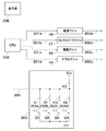
図1は、本発明の実施の形態に係る画像形成装置の全体構成図である。 FIG. 1 is an overall configuration diagram of an image forming apparatus according to an embodiment of the present invention.
より具体的には、図1は、電子写真方式でタンデム型の中間転写ベルトを有するカラー画像形成装置の一例を示す概略構成図である。 More specifically, FIG. 1 is a schematic configuration diagram showing an example of a color image forming apparatus having an electrophotographic tandem intermediate transfer belt.
この画像形成装置は、イエロー色の画像を形成する画像形成部1Yと、マゼンタ色の画像を形成する画像形成部1Mと、シアン色の画像を形成する画像形成部1Cと、ブラック色の画像を形成する画像形成部1Bkの4つの画像形成部を備える。
The image forming apparatus includes an
これら4つの画像形成部1Y,1M,1C,1Bkは一定の間隔において一列に配置される。さらに、その下方にカセット17、手差しトレイ20を配置し、記録媒体の搬送パス18を縦に配置し、その上方に定着ユニット16を備えている。
These four
次に、個々のユニットについて詳しく説明する。 Next, each unit will be described in detail.
各画像形成部1Y,1M,1C,1Bkには、それぞれ像担持体としてのドラム型の電子写真感光体(像担持体:以下感光ドラムという)2a,2b,2c,2dが設置されている。
Each of the
各感光ドラム2a,2b,2c,2dの周囲には、一次帯電器3a,3b,3c,3d、現像装置4a,4b,4c,4d、転写ローラ5a,5b,5c,5d、ドラムクリーナ装置6a、6b、6c、6dがそれぞれ配置されている。
Around each
一次帯電器3a,3b,3c,3dと現像装置4a,4b,4c,4dとの間の下方には、レーザ露光装置7が設置されている。
A
各感光ドラム2a,2b,2c,2dは、負帯電のOPC感光体でアルミニウム製のドラム基体上に光導電層を有しており、駆動装置(不図示)によって矢印方向(時計回り方向)に所定のプロセス速度で回転駆動される。
Each of the
一次帯電器3a,3b,3c,3dは、帯電バイアス電源(不図示)から印加される帯電バイアスによって各感光ドラム2a,2b,2c,2dの表面を負極性の所定電位に均一に帯電する。
The
感光ドラム下方に配置されるレーザ露光装置7は、与えられる画像情報(画像データ)の時系列電気デジタル画素信号に対応した発光を行うレーザ発光部、ポリゴンレンズ、反射ミラー等で構成されている。
The
レーザ露光装置7は、各感光ドラム2a、2b、2c、2dに露光をすることによって、各一次帯電器3a,3b,3c,3dで帯電された各感光ドラム2a,2b,2c,2dの表面に画像情報に応じた各色の静電潜像を形成する。レーザ露光装置7の詳細構成に関しては後述する。
The
各現像装置4a,4b,4c,4dは、それぞれイエロートナー、シアントナー、マゼンタトナー、ブラックトナーが収納されている。各現像装置4a,4b,4c,4dは、各感光ドラム2a,2b,2c,2d上に形成される各静電潜像に各色のトナーを付着させることで、各静電潜像は、トナー像として現像(可視像化)される。
Each developing
転写ローラ5a,5b,5c,5dは、各一次転写部32a〜32dにて中間転写ベルト8を介して各感光ドラム2a,2b,2c,2dに当接可能に配置されている。
The
各感光ドラム2上のトナー像を順次中間転写ベルト8上に転写し重ね合わせていくことでトナー像は転写される。
The toner images are transferred by sequentially transferring the toner images on the respective
ドラムクリーナ装置6a、6b、6c、6dは、クリーニングブレード等で構成され、感光ドラム2上の一次転写時の残留した転写残トナーを、感光ドラム2から掻き落とし、感光ドラム2の表面を清掃する。
The drum cleaners 6a, 6b, 6c, and 6d are configured by a cleaning blade or the like, and scrape off residual transfer toner remaining on the
中間転写ベルト8は、各感光ドラム2a,2b,2c,2dの上面側に配置されて、二次転写対向ローラ10とテンションローラ11間に張架されている。また、二次転写対向ローラ10は、二次転写部34において、中間転写ベルト8を介して二次転写ローラ12と当接可能に配置されている。
The
中間転写ベルト8は、ポリカーボネート、ポリエチレンテレフタレート樹脂フィルム、ポリフッ化ビニリデン樹脂フィルム等のような誘電体樹脂によって構成されている。中間転写ベルト8に転写された画像(トナー画像)は二次転写部34において、給紙ユニットから搬送された記録媒体上に転写される。
The
以上に示したプロセスにより各トナーによる画像形成が行われる。 Image formation with each toner is performed by the process described above.
給紙ユニットは、記録媒体Pを収納するためのカセット17、手差しトレイ20、カセット内もしくは手差しトレイから記録媒体Pを一枚ずつ送り出すためのピックアップローラ(不図示)を備える。
The paper feed unit includes a
また、給紙ユニットは、各ピックアップローラから送り出された記録媒体Pをレジストローラまで搬送するための給紙ローラ、搬送パス18、画像形成部1の画像形成タイミングに合わせて記録媒体Pを二次転写領域へ送り出すためのレジストローラ19を備える。
Further, the paper feeding unit places the recording medium P on the secondary basis in accordance with the image forming timing of the paper feeding roller, the
定着ユニット16は、内部にアルミナヒータなどの熱源を備えた定着ローラ16aと、定着ローラ16aに加圧される加圧ローラ16b(このローラに熱源を備える場合もある)からなる。
The
また、定着ユニット16の下流には、定着ユニット16から排出された記録媒体Pを排紙トレイ22に導き出すための外排紙ローラ21が配設される。
Further, an
制御ユニットは、上記各ユニットの動作を制御するための制御基板が備えられたコントローラボックス(コントローラユニット)35と、制御基板に電源を供給するための電源基板が備えられた電源ボックス(電源ユニット)36によって構成されている。 The control unit includes a controller box (controller unit) 35 provided with a control board for controlling the operation of each unit, and a power supply box (power supply unit) provided with a power supply board for supplying power to the control board. 36.
コントローラボックス35と電源ボックス36を効率的に冷却するための冷却装置としてコントローラファン37や電源ファン38が備えられている。また制御基板によって駆動制御されるモータ(不図示)を冷却するための駆動ファン39や感光ドラム2a〜2dの温度を一定に保つためのドラムファン40によって冷却装置が構成されている。
As a cooling device for efficiently cooling the
図2は、図1における各ファンを含む冷却装置の制御ブロック図である。 FIG. 2 is a control block diagram of a cooling device including each fan in FIG.
電源ファン38、コントローラファン37、駆動ファン39、ドラムファン40にはそれぞれCPU204の送出する駆動信号201a〜201dが接続されており、各駆動信号201によって、各ファンはオン/オフ制御される。
The
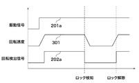
図3は、図2における電源ファンの動作シーケンスを示す図である。 FIG. 3 is a diagram showing an operation sequence of the power supply fan in FIG.
電源ファン38に接続されている駆動信号201aがHとなると、電源ファン38は回転を開始する。このとき、電源ファン38の回転速度301が一定以上になるとファン出力信号202aはLからHへと変化する。
When the
電源ファン38の内部には、ファンロータ(不図示)の回転によって変化する磁界を検出し、電気信号に変換するためのホール素子が内蔵されており、ホール素子の検出信号によって電源ファン38の動作状態を検出している。
The
図2に戻り、それぞれのファン出力信号202a〜202dは分圧回路203に送出される。分圧回路203は、ファン出力信号202a〜202dに基づいてオン/オフ動作する複数のスイッチ(トランジスタ)と、スイッチにそれぞれ直列に接続されるとともに互いに並列に接続され異なった抵抗値を有する複数の抵抗を有する。そして、分圧回路203は、複数の抵抗のうちスイッチがオンされている抵抗による合成抵抗と基準電圧に接続された基準抵抗との分圧によって基準電圧に応じたファン回転検出信号205を出力する。
Returning to FIG. 2, the fan output signals 202 a to 202 d are sent to the
ファン出力信号202a〜202dは、それぞれトランジスタQ1〜Q4に接続されており、ファン回転のロックが検出されると各トランジスタがオフされる。
The
トランジスタがオンした際、オンしたトランジスタに直列接続された抵抗と基準抵抗RSによる分圧によって決まる基準電圧Vccに応じた電圧をCPU204は検出する。なお、分圧抵抗R1〜R4は、それぞれR1を基準nΩとして、R2=n+xΩ、R3=n+2xΩ、R4=n+3xΩと、比例した抵抗値を持つように構成されている。
When the transistor is turned on , the
これにより、分圧回路203は、各抵抗の組み合わせによってそれぞれ異なる電圧を有するファン回転検出信号を出力することが可能である。分圧回路203によって電圧レベルに変換されたファン回転検出信号205はCPU204のA/D変換ポートに入力される。
Thereby, the
CPU204は、入力されたファン回転検出信号205の電圧をデジタル値へ変換することで、ファン回転検出信号205の電圧レベルを検出する。
The
図4は、図2における各ファンの状態を表すファン状態判定テーブル(a)とその各モードにおける電圧のグラフ(b)を示す図である(1)。 FIG. 4 is a diagram (1) showing a fan state determination table (a) showing the state of each fan in FIG. 2 and a voltage graph (b) in each mode.
ファン状態判定テーブルは、ファン出力信号202a〜202dに対応した出力電圧と、オンされているトランジスタに直列に接続された抵抗との組み合わせを示すテーブルである。このファン状態判定テーブルは、CPUに接続されるメモリ(不図示)に記憶されている。
The fan state determination table is a table showing combinations of output voltages corresponding to the
CPU204は、予め算出しておいた図4のファン状態判定テーブルと入力された電圧レベルを比較することで、ファンの回転状態が正常であるか否かの判定を行う。また、判定結果は表示部206に通知され、故障である場合には故障表示を行う。
The
図4のファン状態判定テーブルは、RSを1kΩとして、R1=1kΩ、R2=2kΩ、R3=3kΩ、R4=4kΩとし、電圧順に各ファンの組み合わせモードを並べたものである。 In the fan state determination table of FIG. 4, RS is set to 1 kΩ, R1 = 1 kΩ, R2 = 2 kΩ, R3 = 3 kΩ, R4 = 4 kΩ, and the combination modes of the fans are arranged in order of voltage.
このとき、全てのファンが動作している場合の検出電圧は1.07Vである。さらに、最も電圧値の近いモードであるR1,R2,R3がオンされた状態において示される電圧1.16Vとの平均値である1.11VをR1,R2,R3,R4の組み合わせにおける上限の閾値とする。また、下限値は1.03Vとなる。つまり、モード15であると判断するための基準値の範囲は、1.03V〜1.11Vである。 At this time, the detected voltage when all the fans are operating is 1.07V. Furthermore, 1.11V which is an average value with the voltage 1.16V shown in the state where R1, R2 and R3 which are the closest voltage values are turned on is the upper limit threshold value in the combination of R1, R2, R3 and R4. And The lower limit value is 1.03V. That is, the range of the reference value for determining that the mode is 15 is 1.03V to 1.11V.
次に、図5のフローチャートを用いてファンの回転検出処理シーケンスを説明する。 Next, the fan rotation detection processing sequence will be described with reference to the flowchart of FIG.
図5は、図2の冷却装置によって実行されるファンの回転検出処理の手順を示すフローチャートである。 FIG. 5 is a flowchart showing a procedure of fan rotation detection processing executed by the cooling device of FIG.
本処理は、図2におけるCPU204の制御の下に実行される。
This process is executed under the control of the
画像形成装置がプリント(画像形成)動作を開始すると、CPU204は、冷却用の各ファンをプリント動作時の組み合わせによって駆動させる(ステップS501)。
When the image forming apparatus starts a printing (image forming) operation, the
このとき、プリント動作において駆動するファンは、コントローラファン37、電源ファン38、駆動ファン39、ドラムファン40であり、各々のファンに対して駆動信号201を送出する(ステップS502)。
At this time, the fans to be driven in the printing operation are the
このとき、回転しているファンは、正常に回転動作しているか否かを判定するためのファン出力信号202a〜202dを送出する。ファン出力信号202a〜202dは、それぞれトランジスタQ1〜Q4をオンし、分圧回路203はRS及びR1〜R4の合成抵抗による分圧を行う。
At this time, the rotating fan sends out
CPU204は、分圧回路203から出力されたファン回転検出信号205を検出する(ステップS503)。そして、CPU204は、ファン状態判定テーブルから出力電圧を参照し、その出力電圧を中心とした所定範囲を基準値として、ファン回転検出信号205の電圧が基準値の範囲内にあるかどうかを判断する(ステップS504)。
The
このとき、CPU204は、分圧回路203から出力されたファン回転検出信号205の電圧が基準値の範囲内であれば正常動作と判定し(ステップS505)、本処理を終了する。また、CPU204は、分圧回路203から出力されたファン回転検出信号205の電圧が基準値の範囲外であれば異常動作と判定する(ステップS506)。
At this time, if the voltage of the fan
さらに、異常動作と判定された場合には、CPU204は、ファン状態判定テーブルに基づき動作しているファンの判定を行う(ステップS507)。つまり、CPU204は、ファン状態判定テーブルによって示された各々の状態閾値のうち、どのモードに相当するかの判定を行う。このとき、判定された動作モードと現在の動作モードとを比較し、異常動作が生じているファンを特定する(ステップS508)。
Further, when it is determined that the operation is abnormal, the
例えば、電源ファン38とドラムファン40のみが駆動されている場合は、ファン状態判定テーブルのモード9に対応し、ファン回転検出信号205の電圧は1.4667Vとなるはずである。しかし、CPU204が2.64Vを検出した場合は、モード1に対応する出力電圧であることからドラムファン40しか駆動されていないことになる。したがって、この場合、CPU204は異常動作が発生しているのは電源ファン38であると特定する。
For example, when only the
さらに、CPU204は、表示部206に対して異常が生じた旨及び異常が発生したファンを表示することで、使用者に対して報知を行う(ステップS509)。ステップS509の処理の後に本処理を終了する。
Further, the
この判定によって故障の発生している全てのファンを特定することが可能である。また、通知手段として表示部を使用することは一例であり、例えばネットワーク等を通じて、故障を通知してもよい。 By this determination, it is possible to identify all fans in which a failure has occurred. In addition, the use of the display unit as the notification unit is an example, and the failure may be notified through a network or the like, for example.
さらに、判定精度を向上するために、イニシャル動作として抵抗R1〜R4の抵抗値を事前に検出し、ファン状態判定テーブルに反映させてもよい。分圧に使用される抵抗は一般的に誤差を有している。判定テーブルに対して各抵抗の抵抗値を反映させることで、各モードに対して十分な検出範囲を持つことが可能である。 Furthermore, in order to improve the determination accuracy, the resistance values of the resistors R1 to R4 may be detected in advance as the initial operation and reflected in the fan state determination table. The resistor used for voltage division generally has an error. By reflecting the resistance value of each resistor in the determination table, it is possible to have a sufficient detection range for each mode.
具体的には、電源オン時において、各ファンを順次動作させ、RS及びR1〜R4の各抵抗による分圧を検出する。このとき検出される電圧は抵抗R1を例として、R1/(RS+R1)×Vccである。Vcc及びRSは固定値であるため、これにより抵抗R1〜R4の抵抗値を検出することが可能である。 Specifically, when the power is turned on, the fans are sequentially operated to detect the divided voltages by the resistors RS and R1 to R4. The voltage detected at this time is R1 / (RS + R1) × Vcc taking the resistor R1 as an example. Since Vcc and RS are fixed values, it is possible to detect the resistance values of the resistors R1 to R4.
図6は、図2における各ファンの状態を表すファン状態判定テーブル(a)とその各モードにおける電圧のグラフ(b)を示す図である(2)。 FIG. 6 is a diagram (2) showing a fan state determination table (a) representing the state of each fan in FIG. 2 and a voltage graph (b) in each mode.
図6は、誤差を含めた判定テーブルを示している。 FIG. 6 shows a determination table including an error.
このとき、一例として、抵抗の誤差範囲は±5%であり、R1=1050Ω、R2=2010Ω、R3=2980Ω、R4=4020Ωである。このとき、誤差を算出しない場合において、モード10における検出範囲は1.441V〜1.367Vである。
At this time, as an example, the error range of the resistance is ± 5%, and R1 = 1050Ω, R2 = 2010Ω, R3 = 2980Ω, and R4 = 4020Ω. At this time, when the error is not calculated, the detection range in
また、誤差を算出する場合には、検出範囲は1.471V〜1.395Vである。つまり誤差を検出しない場合に対して、正常に検出できる検出範囲を40%程度改善することが可能である。 When calculating the error, the detection range is 1.471V to 1.395V. That is, it is possible to improve the detection range that can be normally detected by about 40% compared to the case where no error is detected.
1 画像形成部
2 感光ドラム
3 一次帯電器
4 現像装置
5 転写ローラ
7 レーザ露光装置
8 中間転写ベルト
37 コントローラファン
38 電源ファン
39 駆動ファン
40 ドラムファン
201 駆動信号
202 ファン出力信号
203 分圧回路
204 CPU
205 ファン回転検出信号
206 表示部
DESCRIPTION OF
205 Fan
Claims (4)
前記複数のファンの各々は駆動された際、駆動されたことを示すファン出力信号を出力し、
前記複数のファンから出力されるファン出力信号によってオン動作する複数のスイッチ、前記複数のスイッチにそれぞれ直列に接続されるとともに互いに並列に接続され異なった抵抗値を有する複数の抵抗、及び該複数の抵抗に接続され基準電圧が印加される基準抵抗を有し、オンした前記スイッチに直列に接続された前記抵抗による合成抵抗と前記基準抵抗との分圧によって前記基準電圧に応じたファン回転検出信号を出力する分圧手段と、
前記複数のファンのうちの駆動されたファンの組み合わせと前記ファン回転検出信号が示す電圧レベルとが規定されたテーブルを記憶する記憶手段と、
前記分圧手段から出力された前記ファン回転検出信号が示す電圧レベルと前記テーブルとに基づき、駆動しているファンの組み合わせを示す動作モードを判定する判定手段と、
前記判定手段により判定された動作モードと現在の動作モードとを比較して、前記駆動されたファンのうち異常動作が生じているファンを特定する特定手段と、
を備えることを特徴とする冷却装置。 In a cooling device having a plurality of fans,
When each of the plurality of fans is driven, it outputs a fan output signal indicating that it is driven,
A plurality of switches that are turned on by a fan output signal output from the plurality of fans; a plurality of resistors that are connected in series to the plurality of switches and that are connected in parallel to each other and having different resistance values; and A fan rotation detection signal corresponding to the reference voltage by dividing the combined resistance of the resistor connected in series with the resistor and the reference resistor, which has a reference resistor connected to the resistor and to which a reference voltage is applied. Voltage dividing means for outputting,
Storage means for storing a table in which a combination of driven fans among the plurality of fans and a voltage level indicated by the fan rotation detection signal are defined;
Determination means for determining an operation mode indicating a combination of fans being driven based on the voltage level indicated by the fan rotation detection signal output from the voltage dividing means and the table ;
A specifying unit that compares the operation mode determined by the determination unit with a current operation mode and specifies a fan in which an abnormal operation occurs among the driven fans;
A cooling device comprising:
請求項1〜3のいずれか1項記載の冷却装置を備え、
前記複数のファンとして少なくとも画像形成装置を制御するコントローラユニットを冷却するファン、前記電源供給のための電源ユニットを冷却するファン、前記画像形成装置に備えられたモータ、および画像形成の際にトナー像が担持される像担持体を所定の温度に保つためのファンを有することを特徴とする画像形成装置。 In an image forming apparatus that forms an image according to image data,
A cooling device according to any one of claims 1 to 3,
A fan that cools at least a controller unit that controls the image forming apparatus as the plurality of fans, a fan that cools the power supply unit for supplying power, a motor provided in the image forming apparatus, and a toner image during image formation An image forming apparatus comprising a fan for maintaining an image carrier on which the toner is carried at a predetermined temperature.
Priority Applications (1)
| Application Number | Priority Date | Filing Date | Title |
|---|---|---|---|
| JP2008100295A JP5252972B2 (en) | 2008-04-08 | 2008-04-08 | Cooling device and image forming apparatus |
Applications Claiming Priority (1)
| Application Number | Priority Date | Filing Date | Title |
|---|---|---|---|
| JP2008100295A JP5252972B2 (en) | 2008-04-08 | 2008-04-08 | Cooling device and image forming apparatus |
Publications (3)
| Publication Number | Publication Date |
|---|---|
| JP2009251356A JP2009251356A (en) | 2009-10-29 |
| JP2009251356A5 JP2009251356A5 (en) | 2011-05-26 |
| JP5252972B2 true JP5252972B2 (en) | 2013-07-31 |
Family
ID=41312121
Family Applications (1)
| Application Number | Title | Priority Date | Filing Date |
|---|---|---|---|
| JP2008100295A Expired - Fee Related JP5252972B2 (en) | 2008-04-08 | 2008-04-08 | Cooling device and image forming apparatus |
Country Status (1)
| Country | Link |
|---|---|
| JP (1) | JP5252972B2 (en) |
Families Citing this family (3)
| Publication number | Priority date | Publication date | Assignee | Title |
|---|---|---|---|---|
| EP2752575B1 (en) * | 2011-09-02 | 2017-07-12 | Toyota Jidosha Kabushiki Kaisha | Fuel supply device for internal combustion engine |
| US9982680B2 (en) * | 2013-10-23 | 2018-05-29 | Hewlett-Packard Development Company, L.P. | Fan operation detection |
| JP6572290B2 (en) | 2017-11-22 | 2019-09-04 | ファナック株式会社 | Electronic equipment abnormality detection device |
Family Cites Families (6)
| Publication number | Priority date | Publication date | Assignee | Title |
|---|---|---|---|---|
| JP2679655B2 (en) * | 1994-11-25 | 1997-11-19 | 日本電気株式会社 | Abnormality judgment circuit for redundant operation system |
| JP2000235338A (en) * | 1999-02-16 | 2000-08-29 | Ricoh Co Ltd | Image forming device |
| JP2001193687A (en) * | 2000-01-12 | 2001-07-17 | Nec Eng Ltd | Faulty fan detection device |
| JP2005031410A (en) * | 2003-07-14 | 2005-02-03 | Konica Minolta Business Technologies Inc | Image forming apparatus |
| JP4095605B2 (en) * | 2004-10-28 | 2008-06-04 | キヤノン株式会社 | Fan control method and apparatus for implementing the same |
| JP4793127B2 (en) * | 2006-06-23 | 2011-10-12 | コニカミノルタビジネステクノロジーズ株式会社 | Image forming apparatus |
-
2008
- 2008-04-08 JP JP2008100295A patent/JP5252972B2/en not_active Expired - Fee Related
Also Published As
| Publication number | Publication date |
|---|---|
| JP2009251356A (en) | 2009-10-29 |
Similar Documents
| Publication | Publication Date | Title |
|---|---|---|
| US8417142B2 (en) | Image forming apparatus having developing device cooling mechanism, and control method therefor | |
| US8983314B2 (en) | Image forming apparatus capable of detecting contact fusion, and relay control apparatus | |
| US20140064756A1 (en) | Image forming apparatus and method | |
| US9465348B2 (en) | Power supply device, image forming apparatus, and voltage output method | |
| JP2008134302A (en) | Heating device and image forming apparatus | |
| JP2007309980A (en) | Image forming apparatus | |
| JP2007309981A (en) | Fixing device and image forming apparatus | |
| JP4900434B2 (en) | Image forming apparatus | |
| JP5153250B2 (en) | Image forming apparatus | |
| JP5252972B2 (en) | Cooling device and image forming apparatus | |
| JP5121579B2 (en) | Image forming apparatus | |
| JP2014002003A (en) | Electronic device | |
| US9042744B2 (en) | Image forming apparatus | |
| JP2011102851A (en) | Image forming apparatus and processing program | |
| JP2013041093A (en) | Image forming apparatus | |
| JP5532404B2 (en) | Image forming apparatus | |
| JP2010117636A (en) | Image forming device | |
| JP2016130830A (en) | Image forming apparatus | |
| JP2012252144A (en) | Faulty driving section determination device | |
| US10908552B2 (en) | Image forming device and method for determining abnormality | |
| JP2008026629A (en) | Image forming apparatus, image forming method, image forming program and recording medium | |
| JP2009282079A (en) | Image forming apparatus and drive control method for the same | |
| JP2022003371A (en) | Image forming apparatus | |
| JP2009288679A (en) | Image forming apparatus | |
| JP2021110774A (en) | Image forming apparatus |
Legal Events
| Date | Code | Title | Description |
|---|---|---|---|
| A521 | Written amendment |
Free format text: JAPANESE INTERMEDIATE CODE: A523 Effective date: 20110407 |
|
| A621 | Written request for application examination |
Free format text: JAPANESE INTERMEDIATE CODE: A621 Effective date: 20110407 |
|
| A977 | Report on retrieval |
Free format text: JAPANESE INTERMEDIATE CODE: A971007 Effective date: 20121010 |
|
| A131 | Notification of reasons for refusal |
Free format text: JAPANESE INTERMEDIATE CODE: A131 Effective date: 20121016 |
|
| A521 | Written amendment |
Free format text: JAPANESE INTERMEDIATE CODE: A523 Effective date: 20121205 |
|
| TRDD | Decision of grant or rejection written | ||
| A01 | Written decision to grant a patent or to grant a registration (utility model) |
Free format text: JAPANESE INTERMEDIATE CODE: A01 Effective date: 20130319 |
|
| A61 | First payment of annual fees (during grant procedure) |
Free format text: JAPANESE INTERMEDIATE CODE: A61 Effective date: 20130416 |
|
| FPAY | Renewal fee payment (event date is renewal date of database) |
Free format text: PAYMENT UNTIL: 20160426 Year of fee payment: 3 |
|
| LAPS | Cancellation because of no payment of annual fees |