JP5251969B2 - Image forming apparatus - Google Patents
Image forming apparatus Download PDFInfo
- Publication number
- JP5251969B2 JP5251969B2 JP2010282623A JP2010282623A JP5251969B2 JP 5251969 B2 JP5251969 B2 JP 5251969B2 JP 2010282623 A JP2010282623 A JP 2010282623A JP 2010282623 A JP2010282623 A JP 2010282623A JP 5251969 B2 JP5251969 B2 JP 5251969B2
- Authority
- JP
- Japan
- Prior art keywords
- sleep state
- transition
- release
- amount
- sleep
- Prior art date
- Legal status (The legal status is an assumption and is not a legal conclusion. Google has not performed a legal analysis and makes no representation as to the accuracy of the status listed.)
- Expired - Fee Related
Links
Images


Classifications
-
- G—PHYSICS
- G06—COMPUTING; CALCULATING OR COUNTING
- G06F—ELECTRIC DIGITAL DATA PROCESSING
- G06F1/00—Details not covered by groups G06F3/00 - G06F13/00 and G06F21/00
- G06F1/26—Power supply means, e.g. regulation thereof
- G06F1/32—Means for saving power
- G06F1/3203—Power management, i.e. event-based initiation of a power-saving mode
- G06F1/3206—Monitoring of events, devices or parameters that trigger a change in power modality
- G06F1/3228—Monitoring task completion, e.g. by use of idle timers, stop commands or wait commands
-
- G—PHYSICS
- G03—PHOTOGRAPHY; CINEMATOGRAPHY; ANALOGOUS TECHNIQUES USING WAVES OTHER THAN OPTICAL WAVES; ELECTROGRAPHY; HOLOGRAPHY
- G03G—ELECTROGRAPHY; ELECTROPHOTOGRAPHY; MAGNETOGRAPHY
- G03G15/00—Apparatus for electrographic processes using a charge pattern
- G03G15/50—Machine control of apparatus for electrographic processes using a charge pattern, e.g. regulating differents parts of the machine, multimode copiers, microprocessor control
- G03G15/5004—Power supply control, e.g. power-saving mode, automatic power turn-off
-
- G—PHYSICS
- G06—COMPUTING; CALCULATING OR COUNTING
- G06F—ELECTRIC DIGITAL DATA PROCESSING
- G06F1/00—Details not covered by groups G06F3/00 - G06F13/00 and G06F21/00
- G06F1/26—Power supply means, e.g. regulation thereof
- G06F1/32—Means for saving power
-
- G—PHYSICS
- G06—COMPUTING; CALCULATING OR COUNTING
- G06F—ELECTRIC DIGITAL DATA PROCESSING
- G06F1/00—Details not covered by groups G06F3/00 - G06F13/00 and G06F21/00
- G06F1/26—Power supply means, e.g. regulation thereof
- G06F1/32—Means for saving power
- G06F1/3203—Power management, i.e. event-based initiation of a power-saving mode
- G06F1/3206—Monitoring of events, devices or parameters that trigger a change in power modality
- G06F1/3209—Monitoring remote activity, e.g. over telephone lines or network connections
-
- G—PHYSICS
- G06—COMPUTING; CALCULATING OR COUNTING
- G06F—ELECTRIC DIGITAL DATA PROCESSING
- G06F1/00—Details not covered by groups G06F3/00 - G06F13/00 and G06F21/00
- G06F1/26—Power supply means, e.g. regulation thereof
- G06F1/32—Means for saving power
- G06F1/3203—Power management, i.e. event-based initiation of a power-saving mode
- G06F1/3206—Monitoring of events, devices or parameters that trigger a change in power modality
- G06F1/3215—Monitoring of peripheral devices
-
- G—PHYSICS
- G06—COMPUTING; CALCULATING OR COUNTING
- G06F—ELECTRIC DIGITAL DATA PROCESSING
- G06F1/00—Details not covered by groups G06F3/00 - G06F13/00 and G06F21/00
- G06F1/26—Power supply means, e.g. regulation thereof
- G06F1/32—Means for saving power
- G06F1/3203—Power management, i.e. event-based initiation of a power-saving mode
- G06F1/3234—Power saving characterised by the action undertaken
- G06F1/3246—Power saving characterised by the action undertaken by software initiated power-off
-
- G—PHYSICS
- G06—COMPUTING; CALCULATING OR COUNTING
- G06F—ELECTRIC DIGITAL DATA PROCESSING
- G06F1/00—Details not covered by groups G06F3/00 - G06F13/00 and G06F21/00
- G06F1/26—Power supply means, e.g. regulation thereof
- G06F1/32—Means for saving power
- G06F1/3203—Power management, i.e. event-based initiation of a power-saving mode
- G06F1/3234—Power saving characterised by the action undertaken
- G06F1/325—Power saving in peripheral device
- G06F1/3284—Power saving in printer
-
- G—PHYSICS
- G06—COMPUTING; CALCULATING OR COUNTING
- G06F—ELECTRIC DIGITAL DATA PROCESSING
- G06F1/00—Details not covered by groups G06F3/00 - G06F13/00 and G06F21/00
- G06F1/26—Power supply means, e.g. regulation thereof
- G06F1/32—Means for saving power
- G06F1/3203—Power management, i.e. event-based initiation of a power-saving mode
- G06F1/3234—Power saving characterised by the action undertaken
- G06F1/329—Power saving characterised by the action undertaken by task scheduling
-
- G—PHYSICS
- G06—COMPUTING; CALCULATING OR COUNTING
- G06F—ELECTRIC DIGITAL DATA PROCESSING
- G06F3/00—Input arrangements for transferring data to be processed into a form capable of being handled by the computer; Output arrangements for transferring data from processing unit to output unit, e.g. interface arrangements
- G06F3/12—Digital output to print unit, e.g. line printer, chain printer
- G06F3/1201—Dedicated interfaces to print systems
- G06F3/1202—Dedicated interfaces to print systems specifically adapted to achieve a particular effect
- G06F3/1218—Reducing or saving of used resources, e.g. avoiding waste of consumables or improving usage of hardware resources
- G06F3/1221—Reducing or saving of used resources, e.g. avoiding waste of consumables or improving usage of hardware resources with regard to power consumption
-
- G—PHYSICS
- G06—COMPUTING; CALCULATING OR COUNTING
- G06F—ELECTRIC DIGITAL DATA PROCESSING
- G06F3/00—Input arrangements for transferring data to be processed into a form capable of being handled by the computer; Output arrangements for transferring data from processing unit to output unit, e.g. interface arrangements
- G06F3/12—Digital output to print unit, e.g. line printer, chain printer
- G06F3/1201—Dedicated interfaces to print systems
- G06F3/1223—Dedicated interfaces to print systems specifically adapted to use a particular technique
- G06F3/1229—Printer resources management or printer maintenance, e.g. device status, power levels
-
- G—PHYSICS
- G06—COMPUTING; CALCULATING OR COUNTING
- G06F—ELECTRIC DIGITAL DATA PROCESSING
- G06F3/00—Input arrangements for transferring data to be processed into a form capable of being handled by the computer; Output arrangements for transferring data from processing unit to output unit, e.g. interface arrangements
- G06F3/12—Digital output to print unit, e.g. line printer, chain printer
- G06F3/1201—Dedicated interfaces to print systems
- G06F3/1278—Dedicated interfaces to print systems specifically adapted to adopt a particular infrastructure
- G06F3/1279—Controller construction, e.g. aspects of the interface hardware
-
- G—PHYSICS
- G06—COMPUTING; CALCULATING OR COUNTING
- G06K—GRAPHICAL DATA READING; PRESENTATION OF DATA; RECORD CARRIERS; HANDLING RECORD CARRIERS
- G06K15/00—Arrangements for producing a permanent visual presentation of the output data, e.g. computer output printers
- G06K15/40—Details not directly involved in printing, e.g. machine management, management of the arrangement as a whole or of its constitutive parts
- G06K15/4055—Managing power consumption, e.g. standby mode
-
- H—ELECTRICITY
- H04—ELECTRIC COMMUNICATION TECHNIQUE
- H04N—PICTORIAL COMMUNICATION, e.g. TELEVISION
- H04N1/00—Scanning, transmission or reproduction of documents or the like, e.g. facsimile transmission; Details thereof
- H04N1/00885—Power supply means, e.g. arrangements for the control of power supply to the apparatus or components thereof
- H04N1/00888—Control thereof
- H04N1/00896—Control thereof using a low-power mode, e.g. standby
-
- Y—GENERAL TAGGING OF NEW TECHNOLOGICAL DEVELOPMENTS; GENERAL TAGGING OF CROSS-SECTIONAL TECHNOLOGIES SPANNING OVER SEVERAL SECTIONS OF THE IPC; TECHNICAL SUBJECTS COVERED BY FORMER USPC CROSS-REFERENCE ART COLLECTIONS [XRACs] AND DIGESTS
- Y02—TECHNOLOGIES OR APPLICATIONS FOR MITIGATION OR ADAPTATION AGAINST CLIMATE CHANGE
- Y02D—CLIMATE CHANGE MITIGATION TECHNOLOGIES IN INFORMATION AND COMMUNICATION TECHNOLOGIES [ICT], I.E. INFORMATION AND COMMUNICATION TECHNOLOGIES AIMING AT THE REDUCTION OF THEIR OWN ENERGY USE
- Y02D10/00—Energy efficient computing, e.g. low power processors, power management or thermal management
-
- Y—GENERAL TAGGING OF NEW TECHNOLOGICAL DEVELOPMENTS; GENERAL TAGGING OF CROSS-SECTIONAL TECHNOLOGIES SPANNING OVER SEVERAL SECTIONS OF THE IPC; TECHNICAL SUBJECTS COVERED BY FORMER USPC CROSS-REFERENCE ART COLLECTIONS [XRACs] AND DIGESTS
- Y02—TECHNOLOGIES OR APPLICATIONS FOR MITIGATION OR ADAPTATION AGAINST CLIMATE CHANGE
- Y02D—CLIMATE CHANGE MITIGATION TECHNOLOGIES IN INFORMATION AND COMMUNICATION TECHNOLOGIES [ICT], I.E. INFORMATION AND COMMUNICATION TECHNOLOGIES AIMING AT THE REDUCTION OF THEIR OWN ENERGY USE
- Y02D30/00—Reducing energy consumption in communication networks
- Y02D30/50—Reducing energy consumption in communication networks in wire-line communication networks, e.g. low power modes or reduced link rate
Landscapes
- Engineering & Computer Science (AREA)
- Theoretical Computer Science (AREA)
- General Engineering & Computer Science (AREA)
- Physics & Mathematics (AREA)
- General Physics & Mathematics (AREA)
- Human Computer Interaction (AREA)
- Signal Processing (AREA)
- Multimedia (AREA)
- Microelectronics & Electronic Packaging (AREA)
- Control Or Security For Electrophotography (AREA)
- Accessory Devices And Overall Control Thereof (AREA)
- Power Sources (AREA)
- Facsimiles In General (AREA)
Description
本発明は、プリンタ、複写機等の画像形成装置に関し、特に画像形成装置の省電力化を図るため、画像形成装置の電力消費量が多い部分への電源供給を低レベルに制限又は停止するスリープ状態への移行が可能な画像形成装置における、当該移行を制御する技術に関する。
BACKGROUND OF THE
プリンタ、複写機等の画像形成装置は、常時連続的に使用されるものではなく、時間帯によって使用頻度が異なる。このため、使用されていない期間の電力消費を抑えるため、当該期間においては、画像形成装置は、電力消費量が多い部分(例えば、定着装置や感光体や現像器等が含まれる画像形成部)への電源供給を停止し、画像形成動作が不可能な省電力状態(スリープ状態)に移行が可能なように構成されているのが一般的である。 Image forming apparatuses such as printers and copiers are not always used continuously, and the frequency of use varies depending on the time of day. For this reason, in order to suppress power consumption during periods not in use, the image forming apparatus consumes a large amount of power during this period (for example, an image forming unit including a fixing device, a photoreceptor, a developing device, and the like). Generally, it is configured to be able to shift to a power saving state (sleep state) in which an image forming operation cannot be performed by stopping power supply to the device.
例えば、特許文献1には、印刷ジョブの終了後にスリープ状態に移行するための予約操作を行うことが可能な画像形成装置が開示されている。これにより、印刷ジョブの終了後に簡単にスリープ状態に移行させることができ、画像形成装置が使用されていない間の電力消費を抑えることができる。
For example,
しかしながら、スリープ状態に移行しても、その後、短時間の内に当該スリープ状態の解除を要求するようなイベント(例えば、印刷ジョブ開始時刻を指定した予約印刷ジョブが入力されているような場合)が入力されているような場合には、スリープ状態移行による省電力効果が充分得られない内に、スリープ状態が解除され、自装置を待機状態(速やかに画像形成動作を開始できる状態)へ復帰させるために、所定量の電力消費を要するウォームアップ動作が行われることになるので、かえって電力消費量を増やしてしまう結果になる場合が生じる。 However, even after the transition to the sleep state, an event requesting the cancellation of the sleep state within a short time (for example, when a reserved print job specifying a print job start time is input) Is entered, the sleep state is canceled and the device returns to the standby state (the state where image forming operation can be started immediately) while the power saving effect due to the transition to the sleep state cannot be obtained sufficiently. Therefore, a warm-up operation that requires a predetermined amount of power consumption is performed, which may result in an increase in power consumption.
本発明は、上述のような問題に鑑みて為されたものであって、省電力効果が得られない状況下でのスリープ状態への移行を防止することが可能な画像形成装置を提供することを目的とする。 The present invention has been made in view of the above problems, and provides an image forming apparatus capable of preventing transition to a sleep state under a situation where a power saving effect cannot be obtained. With the goal.
上記目的を達成するため、本発明の一形態に係る画像形成装置は、 画像形成動作が実行不可能なスリープ状態を解除し、画像形成動作が可能な待機状態への復帰を、その解除時期を指定して要求する解除イベントの発生を監視する監視手段と、前記解除イベントが発生した場合に、当該解除イベントの識別子とその解除開始時期とを記憶する記憶手段と、自装置が待機状態にある場合において、スリープ状態への移行を要求する移行イベントが発生したときに、前記記憶手段に当該移行イベントの移行開始時期より解除開始時期が後の前記解除イベントが記憶されている場合に、前記移行イベントの移行開始時期から、前記後の解除開始時期の内、最初に到来する前記解除開始時期までの期間において待機状態を維持するのに要する電力量を算出することにより、当該期間において節電可能な節電量を算出するとともに、スリープ状態に移行後、前記解除開始時期において当該スリープ状態を解除することとした場合に、スリープ状態から待機状態に復帰するのに要する復帰電力量を算出する算出手段と、前記節電量の方が、前記復帰電力量より多い場合にスリープ状態に移行させ、多くない場合には、待機状態を維持する状態制御手段と、を備える。 In order to achieve the above object, an image forming apparatus according to an aspect of the present invention cancels a sleep state in which an image forming operation cannot be performed, and returns to a standby state in which the image forming operation can be performed. Monitoring means for monitoring the occurrence of a release event that is designated and requested, storage means for storing an identifier of the release event and the release start time when the release event occurs, and the own apparatus is in a standby state In the case, when the transition event requesting the transition to the sleep state occurs, the transition is performed when the storage event stores the release event whose release start time is later than the transition start time of the transition event. The amount of power required to maintain the standby state in the period from the event transition start time to the first release start time that comes first among the subsequent release start times By calculating, the power saving amount that can be saved in the period is calculated, and after the transition to the sleep state, when the sleep state is canceled at the release start timing, the sleep state is returned to the standby state. Calculation means for calculating the amount of return power required for the state, and state control means for shifting to the sleep state when the power saving amount is larger than the return power amount, and maintaining the standby state when the amount is not large, Prepare.
前記算出手段は、自装置内の環境温度を測定する温度測定手段と、前記環境温度と待機状態の維持に必要な単位時間当たりの消費電力との対応関係を記憶している消費電力記憶手段と、前記消費電力記憶手段に記憶されている対応関係に基づいて、前記移行開始時期における環境温度に対応する前記消費電力を決定し、決定した前記消費電力に基づいて前記移行開始時期から前記解除開始時期までの期間に節電可能な電力量を算出する節電量算出手段と、前記移行開始時期からの経過時間と定着装置の温度との対応関係を記憶している温度記憶手段と、前記温度記憶手段に記憶されている対応関係に基づいて前記移行開始時期から前記解除開始時期まで時間が経過した後の温度を予測する予測手段と、予測温度と予測温度から待機状態時の定着装置の温度まで昇温させるのに必要な消費電力との対応関係を記憶している昇温消費電力記憶手段と、前記昇温消費電力記憶手段に記憶されている対応関係に基づいて、前記予測手段によって予測された予測温度に対応する前記消費電力を決定し、決定した前記消費電力に基づいて前記復帰電力量を算出する復帰電力量算出手段と、を有することとすることができる。 The calculation means includes a temperature measurement means for measuring an environmental temperature in the device itself, and a power consumption storage means for storing a correspondence relationship between the environmental temperature and power consumption per unit time necessary for maintaining a standby state. The power consumption corresponding to the environmental temperature at the transition start time is determined based on the correspondence stored in the power consumption storage means, and the cancellation start is started from the transition start time based on the determined power consumption. A power saving amount calculating means for calculating an amount of power that can be saved in a period until the time, a temperature storage means for storing a correspondence relationship between an elapsed time from the transition start time and a temperature of the fixing device, and the temperature storage means Predicting means for predicting the temperature after a lapse of time from the transition start time to the release start time based on the correspondence stored in the Based on the correspondence stored in the temperature rise power consumption storage means, the temperature rise consumption power storage means storing the correspondence relation with the power consumption required to raise the temperature to the temperature of the device, the prediction And a return power amount calculating means for determining the power consumption corresponding to the predicted temperature predicted by the means and calculating the return power amount based on the determined power consumption.
前記解除イベントには、印刷開始時期を前記解除開始時期として指定した時刻指定印刷の指定の受け取り、スリープ状態の解除時刻の指定の受け取り、スリープ状態への移行禁止時間帯の指定の受け取りの内の少なくとも1つの指定の受け取りが含まれることとすることができる。
又、本発明の別の一形態に係る印刷システムは、端末装置と、端末装置とネットワークで接続された画像形成装置とからなる印刷システムであって、画像形成動作が可能な待機状態から、画像形成動作が実行不可能なスリープ状態への移行を要求するスリープ移行要求を前記端末装置から受付ける受付手段と、スリープ状態を解除し、待機状態への復帰を要求する解除イベントの発生を監視する監視手段と、前記解除イベントが発生した場合に、当該解除イベントの識別子とその解除開始時期とを記憶する記憶手段と、自装置が待機状態にある場合において、前記スリープ移行要求を受付けたときに、前記記憶手段に当該移行イベントの移行開始時期より解除開始時期が後の前記解除イベントが記憶されている場合に、
前記移行イベントの移行開始時期から、前記後の解除開始時期の内、最初に到来する前記解除開始時期までの期間において待機状態を維持するのに要する電力量を算出することにより、当該期間において節電可能な節電量を算出するとともに、スリープ状態に移行後、前記解除開始時期において当該スリープ状態を解除することとした場合に、スリープ状態から待機状態に復帰するのに要する復帰電力量を算出する算出手段と、前記節電量の方が、前記復帰電力量より多い場合にスリープ状態に移行させ、多くない場合には、待機状態を維持する状態制御手段と、を有する。
The release event includes: designation of time-designated printing that designates the print start time as the release start time, receipt of designation of the release time of the sleep state, receipt of designation of the time period for prohibiting the transition to the sleep state At least one designation receipt may be included.
A printing system according to another aspect of the present invention is a printing system including a terminal device and an image forming apparatus connected to the terminal device via a network. A receiving unit that accepts a sleep transition request for requesting transition to a sleep state where a forming operation cannot be performed from the terminal device, and a monitor that monitors occurrence of a release event that cancels the sleep state and requests return to the standby state Means, when the release event occurs, storage means for storing the identifier of the release event and its release start time, and when the device is in a standby state, when the sleep transition request is received, When the release event whose release start time is later than the transfer start time of the transfer event is stored in the storage means,
By calculating the amount of power required to maintain the standby state in the period from the transition start time of the transition event to the release start time that comes first among the subsequent release start times, Calculation that calculates the amount of power that can be saved and calculates the amount of return power required to return from the sleep state to the standby state when the sleep state is canceled at the release start time after transitioning to the sleep state And a state control unit that shifts to a sleep state when the power saving amount is larger than the return power amount, and maintains a standby state when the power saving amount is not larger.
上記構成を備えることにより、スリープ状態に移行した場合の移行開始時期からスリープ状態の解除開始時期までの節電量と、スリープ状態に移行した場合に、スリープ状態から待機状態に復帰するのに要する復帰電力量とがそれぞれ算出され、節電量の方が復帰電力量より多い場合に限り、スリープ状態に移行されるように制御されるので、省電力効果が得られないことが予測される状況下でのスリープ状態への移行を有効に防止することができる。 With the above configuration, the amount of power saved from the transition start time to the sleep start cancellation time when transitioning to the sleep state, and the recovery required to return from the sleep state to the standby state when transitioning to the sleep state Under the circumstances where power consumption is calculated, and only when the power saving amount is greater than the return power amount, control is made to enter the sleep state, so that it is predicted that the power saving effect will not be obtained. Can be effectively prevented from entering the sleep state.
ここで、前記画像形成装置は、自装置がスリープ状態にある場合に、スリープ状態の解除要求を受け取る受取手段を備え、前記算出手段は、現在進行中のスリープ状態の移行開始時期から前記解除要求受取時までの間において節電可能な節電量を算出するとともに、前記解除要求受取時において、前記スリープ状態を解除することとした場合に、待機状態に復帰するのに要する復帰電力量を算出し、
前記制御手段は、前記節電量の方が、前記復帰電力量より多い場合に前記スリープ状態を解除し、待機状態に移行させることとしてもよい。
The image forming apparatus includes a receiving unit that receives a request for canceling a sleep state when the image forming apparatus is in a sleep state, and the calculation unit is configured to receive the cancel request from a sleep state transition start time that is currently in progress. Calculating the amount of power that can be saved until the time of reception, and calculating the amount of return power required to return to the standby state when the release request is received and the sleep state is to be canceled;
The control means may release the sleep state and shift to a standby state when the power saving amount is larger than the return power amount.
これにより、自装置がスリープ状態にある場合に、その解除要求が有った場合に、進行中のスリープ状態の移行開始時期から解除要求受取時までの間において節電可能な節電量と、解除要求受取時にスリープ状態を解除することとした場合において待機状態に復帰するのに要する復帰電力量とがそれぞれ算出され、節電量の方が復帰電力量より多い場合に、スリープ状態が解除されるように制御されるので、省電力効果が得られる場合に、効果的にスリープ解除を行わせることができる。 As a result, when the device is in the sleep state, if there is a release request, the power saving amount that can be saved between the start of the transition to the sleep state in progress and the release request reception, and the release request When the sleep state is canceled at the time of reception, the return power amount required to return to the standby state is calculated, and the sleep state is canceled when the power saving amount is larger than the return power amount. Therefore, the sleep release can be effectively performed when a power saving effect is obtained.
ここで、前記印刷システムにおいて、前記受付手段はさらに、前記端末装置から移行開始時期指定のスリープ状態への移行の可否についての問い合わせを受付け、前記算出手段は、さらに、前記問い合わせがあったときに、前記問い合わせに係るスリープ状態の移行開始時期より開始時期が後の前記解除イベントが記憶されている場合に、前記スリープ状態への移行開始時期から、前記後の解除開始時期の内、最初に到来する前記解除開始時期までの期間において待機状態を維持するのに要する電力量を算出することにより、当該期間において節電可能な節電量を算出するとともに、スリープ状態に移行後、前記解除開始時期において当該スリープ状態を解除することとした場合に、スリープ状態から待機状態に復帰するのに要する復帰電力量を算出し、前記画像形成装置は、前記節電量の方が、前記復帰電力量より多い場合に前記スリープ状態への移行が可能と判定し、多くない場合には、前記スリープ状態への移行が不可能と判定する判定手段と、判定結果を前記端末装置に通知する通知手段と、を有し、前記端末装置は、前記スリープ状態への移行が可能な場合に限り、前記スリープ状態への移行指示を受け付けることとしてもよい。 Here, in the printing system, the accepting unit further accepts an inquiry from the terminal device as to whether or not it is possible to shift to the sleep state designated by the transition start time, and the calculating unit further receives the inquiry. , When the release event having a start time later than the sleep state transition start time related to the inquiry is stored, the first arrival of the subsequent release start time from the sleep state transition start time By calculating the amount of power required to maintain the standby state during the period until the release start time, the power saving amount that can be saved in the period is calculated, and after entering the sleep state, Return power required to return from the sleep state to the standby state when the sleep state is canceled The image forming apparatus determines that the transition to the sleep state is possible when the power saving amount is larger than the return power amount, and the transition to the sleep state is not performed when the power saving amount is not large. A determination unit that determines that the determination is impossible, and a notification unit that notifies the terminal device of the determination result, and the terminal device shifts to the sleep state only when the shift to the sleep state is possible. An instruction may be accepted.
これにより、スリープ状態への移行指示をユーザから受付ける前に、スリープ状態への移行可否が画像形成装置に対して問い合わせられ、当該移行が可能な場合に限り、ユーザからスリープ状態への移行指示を受付けるように制御されるので、ユーザから無駄なスリープ移行指示を受付けるのを回避することができる。又、ユーザ側から見れば、無駄なスリープ移行指示をしなくてすみ、ユーザの利便性の向上を図ることができる。 Thus, before accepting an instruction to enter the sleep state from the user, the image forming apparatus is inquired of whether or not to enter the sleep state, and the instruction to enter the sleep state is issued from the user only when the transition is possible. Since it is controlled to accept, it is possible to avoid receiving a useless sleep transition instruction from the user. Further, when viewed from the user side, it is not necessary to give a useless sleep transition instruction, and the convenience of the user can be improved.
ここで、前記印刷システムにおいて、前記端末装置は、前記画像形成装置がスリープ状態にあるか否かを問い合わせる問合せ手段と、スリープ状態にある場合に、そのスリープ状態を継続するか否かについての指示を受付けるための画面を表示させる表示制御手段と、を有することとしてもよい。
これにより、画像形成装置がスリープ状態にある場合に、スリープ状態を継続するか否かについての指示を受付けるための画面が端末装置に表示されるので、ユーザは、表示画面を介してスリープ状態を継続するか否かを適切なタイミングで判断し、指示することができる。
Here, in the printing system, the terminal device inquires whether or not the image forming apparatus is in a sleep state, and an instruction as to whether or not to continue the sleep state when the image forming apparatus is in a sleep state. Display control means for displaying a screen for accepting.
As a result, when the image forming apparatus is in the sleep state, a screen for receiving an instruction as to whether or not to continue the sleep state is displayed on the terminal device, so that the user can enter the sleep state via the display screen. Whether or not to continue can be determined and instructed at an appropriate timing.
ここで、前記印刷システムにおいて、前記受付手段は、さらに、前記端末装置からスリープ状態の解除要求を受取り、前記算出手段は、現在進行中のスリープ状態の移行開始時期から前記解除要求受取時までの間において節電可能な節電量を算出するとともに、前記解除要求受取時において、前記スリープ状態を解除することとした場合に、待機状態に復帰するのに要する復帰電力量を算出し、前記判定手段は、前記節電量の方が、前記復帰電力量より多い場合に節電可能と判定し、多くない場合に節電不可能と判定し、前記通知手段は、節電可否の判定結果を前記端末装置に通知し、前記状態制御手段は、節電可能な場合に、前記スリープ状態を解除して、待機状態に移行させ、前記端末装置は、節電不可能な場合に、スリープ状態を強制解除するか否かについての指示を受け取るための画面を表示させることとしてもよい。 Here, in the printing system, the accepting unit further receives a request for canceling the sleep state from the terminal device, and the calculating unit is configured to receive the request for canceling the sleep request from the transition start time of the sleep state currently in progress. And calculating a return power amount required to return to the standby state when the sleep request is canceled when the release request is received. When the power saving amount is larger than the return power amount, it is determined that power saving is possible, and when it is not large, it is determined that power saving is impossible, and the notification means notifies the terminal device of the determination result of whether or not power saving is possible. The state control means cancels the sleep state when power saving is possible and shifts to the standby state, and the terminal device forces the sleep state when power saving is impossible. It is also possible to display a screen for receiving an indication of whether dividing.
これにより、端末装置からスリープ状態の解除要求があった場合に、当該解除要求受取時にスリープ状態を解除することによって、節電効果が得られない場合には、端末装置の表示画面を介して当該解除を実行するか否かについてユーザの指示を受付けることができるので、ユーザの意向を反映した形で、スリープの解除の実行可否を決定することができる。 As a result, when there is a request for canceling the sleep state from the terminal device, if the power saving effect cannot be obtained by canceling the sleep state when receiving the cancel request, the cancel is performed via the display screen of the terminal device. Therefore, it is possible to determine whether or not to cancel the sleep in a form that reflects the user's intention.
(実施の形態)
[1]印刷システムの構成
以下、本発明の一形態の印刷システムの実施の形態について説明する。図1は、本実施の形態に係る印刷システム1の構成を示す図である。同図に示すように、印刷システム1は、画像形成装置100(ここでは、画像形成装置100は、タンデム型カラーデジタルプリンタとする。)とパーソナルコンピュータからなる端末装置(以下、「PC」という。)101、102から構成される。
(Embodiment)
[1] Configuration of Printing System Hereinafter, an embodiment of a printing system according to an embodiment of the present invention will be described. FIG. 1 is a diagram illustrating a configuration of a
画像形成装置100とPC101、102とは、ネットワーク(例えば、LAN(Local Area Network))103で接続されている。
[2]画像形成装置の構成
図2は、画像形成装置100の主要部の機能構成を示すブロック図である。画像形成装置100は、プリント部10、画像読取部20、操作パネル30、温度センサ40、制御部60等から構成される。
The
[2] Configuration of Image Forming Apparatus FIG. 2 is a block diagram illustrating a functional configuration of main parts of the
プリント部10は、電子写真プロセスによって制御部60から出力される画像データに基づくトナー像を記録シート上に形成して出力する。プリント部10は、画像プロセス部11、給紙部12、定着装置13等を備える。画像プロセス部11は、制御部60から出力される画像データに基づくトナー像を形成し、形成したトナー像を、給紙部12から供給される記録シート上に転写する。定着装置13は、定着ローラと加圧ローラなどから構成され、記録シート上に転写されたトナー像を熱定着させる。定着ローラの近傍には図示しない定着ローラ用温度センサが配置され、定着ローラの外周面の周方向の表面温度を所定の時間間隔で検出し、検出結果を制御部60に出力する。
The
画像読取部20は、画像を読取り、画像データを生成して、制御部60に出力する。操作パネル30は、液晶ディスプレイ、液晶ディスプレイに積層されたタッチパネルや各種指示を入力するための操作ボタン等から構成され、タッチパネルや操作ボタン等の操作を介してユーザから各種指示の入力を受け付ける。液晶ディスプレイには、印刷設定画面等の操作画面や印刷結果等の各種表示情報が表示される。
The
温度センサ40は、画像形成装置100の内部に設けられ、画像形成装置100の内部の環境温度を測定し、測定結果を制御部60に出力する。
制御部60は、CPU(Central Processing Unit)601、通信インターフェース(I/F)部602、ROM(Read Only Memory)603、RAM(Random Access Memory)604、画像データ記憶部605、電源制御部606、テーブル記憶部607、スリープ解除イベント記憶部608などを備える。
The
The
通信I/F部602は、LANカード、LANボードといったLANに接続するためのインターフェースである。ROM603には、プリント部10、画像読取部20、操作パネル30、温度センサ40を制御するためのプログラム、後述するスリープ解除イベント登録処理やスリープ状態移行制御処理を実行するためのプログラムなどが格納されている。
The communication I /
RAM604は、CPU601のプログラム実行時のワークエリアとして用いられる。
画像データ記憶部605は、通信I/F部602や画像読取部20を介して入力された、印刷用の画像データを記憶している。CPU601は、ROM603に格納されている各種プログラムを実行することにより、プリント部10、画像読取部20、操作パネル30、温度センサ40等を制御し、さらに、後述するスリープ解除イベント登録処理やスリープ状態移行制御処理を実行する。
The
The image
電源制御部606は、後述する電源部700への通電のオン・オフを切替えることにより、プリント部10への電源供給のオン・オフを切替える制御を行う。図3は、電源部700の構成と電源部700からの電源供給の対象となる主要構成要素との関係を示す図である。同図に示すように電源部700は、電源供給容量が大きい主電源701と電源供給容量が小さい副電源702から構成され、主電源701は、プリント部10と、副電源702は、操作パネル30、制御部60と接続されている。
The power
電源制御部606は、主電源701への通電のオン・オフを切替えることにより、プリント部10への電源供給のオン・オフを切替える。そして、制御部60及び操作パネル30に対しては、副電源702から電源供給される。
図2の説明に戻って、テーブル記憶部607は、平均消費電力テーブル、スリープ開始後温度予測テーブル、昇温消費電力テーブルなどを記憶している。
The
Returning to the description of FIG. 2, the
ここで、「平均消費電力テーブル」とは、画像形成装置100の内部の環境温度と、当該環境温度下で定着ローラの表面温度を待機温度に維持するために必要な、単位時間当たりの平均消費電力(ワット)との対応関係を示すテーブルのことをいい、各環境温度における平均消費電力の値は、画像形成装置100の製造者側で予め測定されて決定される。又、「待機温度」とは、すぐにトナー像の熱定着を行うことが可能な所定の温度(例えば、定着温度(約160〜180℃)又は、定着温度より10〜20℃程度低い温度)のことをいう。
Here, the “average power consumption table” refers to the average consumption per unit time required to maintain the environmental temperature inside the
図4は、平均消費電力テーブルの具体例を示す。同図のA1〜A8は、決定された各平均消費電力の値を示し、当該値は、環境温度が高くなるに従って、小さくなる(A1>A2>A3>A4>A5>A6>A7>A8)。環境温度が高くなるに従って、定着ローラからの放熱量が少なくなるからである。
又、「スリープ開始後温度予測テーブル」とは、自装置を、待機状態(定着ローラの表面温度を待機温度に維持した状態)からスリープ状態(プリント部10に電源供給しない状態)に移行してから(スリープ状態移行開始後)の経過時間と、当該経過時間後の定着ローラの予測表面温度との対応関係を示すテーブルのことをいい、予測表面温度は、予め所定の環境温度下(例えば、25℃)で画像形成装置100の製造者側で予め実測されて決定される。なお、当該テーブルは、環境温度に応じて複数のテーブルを作成しておくこととしてもよい。
FIG. 4 shows a specific example of the average power consumption table. A1 to A8 in the figure indicate the determined average power consumption values, and the values decrease as the environmental temperature increases (A1>A2>A3>A4>A5>A6>A7> A8). . This is because the amount of heat released from the fixing roller decreases as the environmental temperature increases.
In addition, the “temperature prediction table after sleep start” refers to a state in which the apparatus shifts from a standby state (a state where the surface temperature of the fixing roller is maintained at a standby temperature) to a sleep state (a state where power is not supplied to the printing unit 10). (After the start of the sleep state transition) and a table showing a correspondence relationship between the estimated surface temperature of the fixing roller after the elapsed time, and the predicted surface temperature is previously set at a predetermined environmental temperature (for example, 25.degree. C.) on the manufacturer side of the
図5は、スリープ開始後温度予測テーブルの具体例を示す。同図の具体例は、待機温度を170℃とした場合における、スリープ開始後の経過時間と定着ローラの予測表面温度との関係を示している。
又、「昇温消費電力テーブル」とは、スリープ状態を解除した時の定着ローラの予測表面温度と当該予測表面温度から待機温度まで昇温させるのに必要な消費電力量との対応関係を示すテーブルのことをいい、各予測表面温度における上記消費電力量は、画像形成装置100の製造者側で予め実測(例えば、所定の温度範囲(例えば、0〜170℃)で表面温度を変えて各表面温度について、上記消費電力量を実測)されて決定される。
FIG. 5 shows a specific example of the temperature prediction table after the start of sleep. The specific example in the figure shows the relationship between the elapsed time after the start of sleep and the predicted surface temperature of the fixing roller when the standby temperature is 170 ° C.
The “temperature increase power consumption table” indicates the correspondence between the predicted surface temperature of the fixing roller when the sleep state is canceled and the power consumption required to raise the temperature from the predicted surface temperature to the standby temperature. This table is a table, and the power consumption at each predicted surface temperature is measured by the manufacturer of the
図6は、昇温消費電力テーブルの具体例を示す。同図のB1〜B8は、決定された上記各消費電力量の値を示し、当該値は、上記の予測表面温度が高くなるに従って小さくなる(B1>B2>B3>B4>B5>B6>B7>B8)。予測表面温度が高くなるに従って、待機温度との温度差が小さくなり、その分、待機温度まで昇温させるのに必要な消費電力量が少なくてすむからである。 FIG. 6 shows a specific example of the temperature rising power consumption table. B1 to B8 in the figure indicate the determined values of the respective power consumption amounts, and the values decrease as the predicted surface temperature increases (B1> B2> B3> B4> B5> B6> B7). > B8). This is because as the predicted surface temperature increases, the temperature difference from the standby temperature decreases, and accordingly, less power is required to raise the temperature to the standby temperature.
図2の説明に戻って、スリープ解除イベント記憶部608は、時間帯別使用履歴テーブルとスリープ解除イベント予約テーブルと、スリープ予約テーブルとを記憶している。
ここで、「時間帯別使用履歴テーブル」とは、画像形成装置100の過去数日(例えば、2日)分の、各所定の時間帯における総印刷枚数を示すテーブルのことをいう。各所定の時間帯における総印刷枚数は、制御部60によってカウントされ、日単位でテーブルにまとめられて、スリープ解除イベント記憶部608に記憶される。スリープ解除イベント記憶部608には、このようにまとめられたテーブルが所定日数(例えば、7日)分記憶され、所定日数分を超えるテーブルが新たに作成されると、最も古い日に作成されたテーブルが制御部60によって削除される。
Returning to the description of FIG. 2, the sleep cancellation
Here, the “use history table by time zone” refers to a table indicating the total number of printed sheets in each predetermined time zone for the past several days (for example, 2 days) of the
そして、記憶されているテーブルの内、予め定められた日数(例えば、2日)分のテーブルを、日付が新しい順に選択し、選択したテーブルに基づいて時間帯別使用履歴テーブルが制御部60によって作成される。時間帯別使用履歴テーブルの作成動作は、電源部700の電源がオンされたときに実行される。
図7は、時間帯別使用履歴テーブルの具体例を示す。同図の具体例では、画像形成装置100は、朝8時から夜9時までの間使用され、使用開始時刻から約1時間(同図では、59分59秒)毎に当該時間帯における総印刷枚数がカウントされ、そのカウント値の予め定められた日数(例えば、2日)分の総数が示されている。
Then, among the stored tables, tables for a predetermined number of days (for example, two days) are selected in the order of date, and the use history table for each time zone is selected by the
FIG. 7 shows a specific example of the usage history table for each time zone. In the specific example of the figure, the
又、「スリープ解除イベント予約テーブル」とは、スリープ状態の解除を要求するイベントであるスリープ解除イベントの識別子と、当該解除が要求される解除時刻との対応関係を示すテーブルのことをいう。スリープ解除イベントには、例えば、印刷開始時刻(すなわち、スリープ状態の解除時刻)を指定した印刷ジョブである「時刻指定印刷ジョブ」やスリープ状態への移行開始時刻とスリープ状態の解除時刻とを指定したスリープ状態への移行要求である「時刻指定スリープ要求」や高使用履歴時間帯の指定などがある。後述するスリープ解除イベント登録処理において、時刻指定印刷ジョブや時刻指定スリープ要求が、PCから入力されると、制御部60は、スリープ解除イベント予約テーブルに、対応する解除時刻を、そのスリープ解除イベント名と対応付けて記録する。
The “sleep release event reservation table” is a table indicating a correspondence relationship between an identifier of a sleep release event that is an event requesting release of the sleep state and a release time at which the release is requested. In the sleep release event, for example, a “time-designated print job” that is a print job in which a print start time (that is, a sleep state release time) is specified, a transition start time to the sleep state, and a sleep state release time are specified. There are “time designation sleep request” which is a request for transition to the sleep state and designation of a high usage history time zone. When a time-designated print job or a time-designated sleep request is input from the PC in a sleep wake event registration process, which will be described later, the
「高使用履歴時間帯」とは、時間帯別使用履歴テーブルの総印刷枚数が、閾値(例えば100枚)を超える時間帯のことをいう。後述するスリープ解除イベント登録処理において、制御部60は、電源部700の電源がオンされた際に、作成した時間帯別使用履歴テーブルを参照して、閾値を超える時間帯があるか否かを判定し、ある場合には、当該時間帯の開始時刻をスリープ状態の解除時刻としてスリープ解除イベント予約テーブルに記録する。図8は、スリープ解除イベント予約テーブルの具体例を示す。
The “high usage history time zone” refers to a time zone in which the total number of printed sheets in the usage history table by time zone exceeds a threshold value (for example, 100 sheets). In a sleep release event registration process to be described later, when the
又、「スリープ予約テーブル」とは、時刻指定スリープ要求の各移行開始時刻を示すテーブルのことをいい、当該要求がPC又は操作パネル30を介して入力されると、制御部60は、対応する移行開始時刻をスリープ予約テーブルに記録し、当該時刻が経過すると、スリープ予約テーブルから削除する。
[3]スリープ解除イベント登録処理
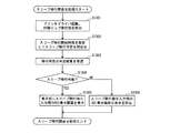
図9は、制御部60が行うスリープ解除イベント登録処理の動作を示すフローチャートである。スリープ解除イベント登録処理は、後述するスリープ状態移行制御処理と並行して実行される。
The “sleep reservation table” refers to a table indicating each transition start time of the time-designated sleep request. When the request is input via the PC or the
[3] Sleep Release Event Registration Process FIG. 9 is a flowchart showing the operation of the sleep release event registration process performed by the
電源部700の電源がオンされると(ステップS901)、制御部60は、時間帯別使用履歴テーブルを作成し、作成した時間帯別使用履歴テーブルを参照して、総印刷枚数が、閾値を超える時間帯があるか否かを判定し(ステップS902)、当該時間帯がある場合には(ステップS902:YES)、当該時間帯の開始時刻をスリープ状態の解除時刻としてスリープ解除イベント予約テーブルに登録する(ステップS905)。
When the power of the
又、制御部60は、PCから時刻指定印刷ジョブの入力が有った場合(ステップS903:YES)、時刻指定印刷ジョブにおいて指定されている印刷開始時刻を、スリープ状態の解除時刻としてスリープ解除イベント予約テーブルに登録する(ステップS905)。
さらに、制御部60は、PC又は操作パネル30から時刻指定スリープ要求が入力されると(ステップS904:YES)、当該要求において指定されるスリープ状態の解除時刻をスリープ状態の解除時刻としてスリープ解除イベント予約テーブルに登録する(ステップS905)。
When the time designated print job is input from the PC (step S903: YES), the
Furthermore, when a time-designated sleep request is input from the PC or the operation panel 30 (step S904: YES), the
ステップS902、ステップS903、ステップS904の判定結果が全て否定的である場合には(ステップS902:NO、ステップS903:NO、ステップS904:NO)、制御部60は、スリープ解除イベント予約テーブルを参照して、解除時刻が経過した(解除時刻が現在時刻よりも前の)スリープ解除イベントがあるか否かを判定し(ステップS906)、ある場合には(ステップS906:YES)、当該スリープ解除イベントをスリープ解除イベント予約テーブルから削除する(ステップS907)
制御部60は、上記のステップS903〜ステップS907の処理を電源部700の電源(副電源702)のオフ指示があるまで(ステップS908:YES)繰り返す。
When the determination results of step S902, step S903, and step S904 are all negative (step S902: NO, step S903: NO, step S904: NO), the
The
[4]スリープ状態移行制御処理
図10は、制御部60が行うスリープ状態移行制御処理の動作を示すフローチャートである。電源部700の電源がオンされると、制御部60は、電源制御部606を介してプリント部10に電源を供給し、定着装置13のウォームアップを開始し、定着ローラの表面温度を待機温度まで昇温させ、自装置を待機状態に移行させた後、後述するスリープ移行イベント監視処理を行う(ステップS1001)。
[4] Sleep State Transition Control Process FIG. 10 is a flowchart showing the operation of the sleep state transition control process performed by the
スリープ状態への移行を要求するスリープ移行イベントが発生した場合には(ステップS1002:YES)、制御部60は、後述するスリープ移行可否判定処理を行う(ステップS1003)。そして、ステップS1003の処理において、スリープ状態への移行が可能と判定された場合には(ステップS1004:YES)、制御部60は、電源制御部606を介して、プリント部10への電源供給を停止させ、自装置をスリープ状態に移行させ(ステップS1005)、電源部700の電源(副電源702)のオフ指示がされたか否かを判定する(ステップS1007)。
When a sleep transition event that requests a transition to the sleep state occurs (step S1002: YES), the
一方、ステップS1003の処理において、スリープ状態への移行が不可能と判定された場合には(ステップS1004:NO)、制御部60は、スリープ状態への移行を抑止し(ステップS1006)、ステップS1007処理に移行する。
又、ステップS1002において、スリープ移行イベントが発生していない場合には(ステップS1002:NO)、制御部60は、ステップS1007の処理に移行する。さらに、制御部60は、ステップS1007の判定結果が肯定的になるまで(ステップS1007:YES)、ステップS1001〜ステップS1006の処理を繰り返す。
On the other hand, if it is determined in step S1003 that the transition to the sleep state is impossible (step S1004: NO), the
In step S1002, when the sleep transition event has not occurred (step S1002: NO), the
次に、制御部60が行うスリープ移行イベント監視処理の動作について説明する。図11は、上記動作を示すフローチャートである。制御部60は、自装置が待機状態に移行後、所定時間(例えば、30分)、印刷ジョブの入力がないか否か、スリープ予約テーブルに記録されている時刻指定スリープ要求の移行開始時刻が到来しているか否か、PC又は操作パネル30からスリープ状態への移行を要求するスリープ移行指示の入力があるか否かをそれぞれ判定し(ステップS1101〜ステップS1103)、何れの判定結果も否定的である場合には(ステップS1101:NO。ステップS1102:NO、ステップS1103:NO)、スリープ移行イベントが未発生と判定する(ステップS1104)。
Next, the operation of the sleep transition event monitoring process performed by the
一方、ステップS1101〜ステップS1103の何れかの判定結果が肯定的であり(ステップS1101:YES又はステップS1102:YES又はステップS1103:YES)、判定時点において、自装置がスリープ状態に移行しておらず(ステップS1105:NO)、判定時点が、高使用履歴時間帯に該当していない場合には(ステップS1106:NO)、スリープ移行イベントが発生したと判定する(ステップS1107)。ステップS1105又はステップS1106の何れかの判定結果が肯定的である場合には(ステップS1105:YES又はステップS1106:YES)、スリープ移行イベントが未発生と判定する(ステップS1104)。 On the other hand, the determination result of any one of steps S1101 to S1103 is affirmative (step S1101: YES or step S1102: YES or step S1103: YES), and the own device has not shifted to the sleep state at the determination time. (Step S1105: NO), if the determination time does not correspond to the high usage history time zone (Step S1106: NO), it is determined that a sleep transition event has occurred (Step S1107). If the determination result of either step S1105 or step S1106 is affirmative (step S1105: YES or step S1106: YES), it is determined that no sleep transition event has occurred (step S1104).
次に、制御部60が行うスリープ移行可否判定処理の動作について説明する。図12は、上記動作を示すフローチャートである。
制御部60は、スリープ移行イベントが発生した場合に(ステップS1002:YES)、スリープ解除イベント予約テーブルを参照して、解除時刻が現在時刻より後のスリープ解除イベントが記録されているか否かを判定する(ステップS1201)。
Next, the operation of the sleep shift enable / disable determination process performed by the
When the sleep transition event occurs (step S1002: YES), the
スリープ解除イベントが記録されている場合には(ステップS1201:YES)、解除時刻が最初に到来するものを、発生したスリープ移行イベントに係るスリープのスリープ解除時刻として特定し(ステップS1202)、現在時刻から特定したスリープ解除時刻までの節電量(S)を算出する(ステップS1203)。
節電量(S)の算出は、以下のようにして行われる。制御部60は、温度センサ40より、現在の環境温度を取得し、テーブル記憶部607に記憶されている平均消費電力テーブルを参照して、取得した環境温度に対応する平均消費電力を特定し、特定した消費電力に、現在時刻から特定したスリープ解除時刻までの経過時間を乗算して節電量(S)を算出する。
When a sleep release event is recorded (step S1201: YES), the first release time is specified as the sleep release time of the sleep transition event that has occurred (step S1202), and the current time The power saving amount (S) until the specified sleep release time is calculated (step S1203).
The calculation of the power saving amount (S) is performed as follows. The
さらに、制御部60は、発生したスリープ移行イベントに応じて自装置をスリープ状態に移行させ、特定したスリープ解除時刻に当該スリープ状態を解除すると仮定した場合において、当該スリープ状態の解除後、自装置を待機状態に復帰させるのに要する復帰電力量(R)を算出する(ステップS1204)。
復帰電力量(R)の算出は、以下のようにして行われる。制御部60は、テーブル記憶部607に記憶されているスリープ開始後温度予測テーブルを参照して、現在時刻から特定したスリープ解除時刻までの経過時間に対応する定着ローラの予測表面温度を特定し、さらに、昇温消費電力テーブルを参照して、特定した予測表面温度に対応する消費電力量を、特定した予測表面温度を待機温度まで昇温させるのに必要な消費電力量として特定する。
Further, when assuming that the
The return power amount (R) is calculated as follows. The
特定した消費電力量に、自装置を待機状態に移行させる際のプリント部10の初期動作やクリーニング動作等に必要な消費電力量(この消費電力量は、ほぼ一定しているため、予め画像形成装置100の製造者により定められ、テーブル記憶部607に記憶されているものとする。)を加算することにより、制御部60は、復帰電力量(R)を算出する。
そして、制御部60は、算出した節電量(S)の方が、算出した復帰電力量(R)より多くなる場合に(ステップS1205:YES)、スリープ状態への移行が可能と判定し(ステップS1206)、多くならない場合に(ステップS1205:NO)、スリープ状態への移行が不可能と判定する(ステップS1207)。
The power consumption required for the initial operation and cleaning operation of the
Then, when the calculated power saving amount (S) is larger than the calculated return power amount (R) (step S1205: YES), the
このように、スリープ移行イベントが発生した場合に、節電量が復帰電力量より多く
、節電効果が得られる場合に限り、スリープ状態への移行がなされるので、省電力効果が得られない場合にスリープ状態に移行され、当該スリープ状態からの復帰のために余分な電力が消費されるのを有効に防止することができる。
(変形例)
以上、本発明を実施の形態に基づいて説明してきたが、本発明が上述の実施の形態に限定されないのは勿論であり、以下のような変形例を実施することができる。
In this way, when the sleep transition event occurs, the transition to the sleep state is made only when the power saving amount is larger than the return power amount and the power saving effect is obtained, and the power saving effect is not obtained. It is possible to effectively prevent the transition to the sleep state and excessive power consumption for returning from the sleep state.
(Modification)
As described above, the present invention has been described based on the embodiment. However, the present invention is not limited to the above-described embodiment, and the following modifications can be implemented.
(1)本実施の形態では、スリープ移行イベントが発生したときに、スリープ移行可否決定処理を行うこととしたが、スリープ移行イベントが発生する前に、PCからスリープ実行可否の問合せを、画像形成装置100に対して行い、当該実行可否の結果に基づいて、スリープ移行要求を受付けるか否かを、PC側が制御することとしてもよい。
具体的には、図13に示すようなスリープ移行問合せ処理を行うこととしてもよい。PCは、ユーザからの指示に応じてプリンタドライバを起動させ、ユーザから印刷ジョブの実行指示を受付けた際に(ステップS1301)、当該印刷ジョブの予測終了時刻を算出(例えば、実行指示受付時刻より所定時間(例えば、1分)後の時刻を予測終了時刻として算出)して、画像形成装置100と通信し、印刷処理の予測終了時刻をスリープ移行開始時刻として指定して、画像形成装置100に対して印刷ジョブ終了後にスリープ状態への移行が可能か否かについての問合せを行う(ステップS1302)。
(1) In the present embodiment, when the sleep transition event occurs, the sleep transition enable / disable determination process is performed. However, before the sleep shift event occurs, an inquiry about whether sleep can be executed is made from the PC. The PC side may control whether or not to accept the sleep transition request based on the result of whether or not the execution is possible.
Specifically, a sleep transition inquiry process as shown in FIG. 13 may be performed. When the PC activates the printer driver in response to an instruction from the user and receives a print job execution instruction from the user (step S1301), the PC calculates a predicted end time of the print job (for example, from the execution instruction reception time). The time after a predetermined time (for example, 1 minute) is calculated as the predicted end time), communicates with the
そして、問合せを受けた画像形成装置100側では、指定されたスリープ移行開始時刻に基づいて、図12に示すスリープ移行可否判定処理の動作と同様の処理を行い、スリープ状態への移行の可否判定を行い、判定結果をPCに送信する。
PCは、画像形成装置100から送信された判定結果を受信し(ステップS1303)、判定結果が、スリープ状態への移行可能である場合には(ステップS1304:YES)、表示部にスリープ移行指示の入力を受付けるためのGUI(Graphic User Interface)の表示画面を表示させ(ステップS1305)、移行可能でない場合には、上記のGUIの表示画面の表示を抑止する(ステップS1306)。なお、GUIの表示画面の表示を抑止する代わりに、スリープ移行指示の入力を無効にするように制御することとしてもよい。
Then, the
The PC receives the determination result transmitted from the image forming apparatus 100 (step S1303). If the determination result can be shifted to the sleep state (step S1304: YES), the PC issues a sleep shift instruction to the display unit. A GUI (Graphic User Interface) display screen for accepting input is displayed (step S1305), and if the transition is not possible, display of the GUI display screen is suppressed (step S1306). Instead of suppressing the display of the GUI display screen, control may be performed so as to invalidate the input of the sleep transition instruction.
これにより、節電効果が得られない場合には、スリープ移行指示の入力が受付けられないように制御されるので、ユーザから無駄なスリープ移行指示を受付けるのを回避することができる。又、ユーザ側から見れば、無駄なスリープ移行指示をしなくてすみ、節電効果がある場合に限ってスリープ移行指示をすることができ、ユーザの利便性の向上を図ることができる。 As a result, when the power saving effect cannot be obtained, control is performed such that the input of the sleep transition instruction is not accepted, so that it is possible to avoid receiving a useless sleep transition instruction from the user. Further, when viewed from the user side, it is not necessary to give a useless sleep shift instruction, and the sleep shift instruction can be issued only when there is a power saving effect, and the convenience of the user can be improved.
(2)本実施の形態では、スリープ移行イベントが発生したときに、スリープ移行可否決定処理を行うこととしたが、スリープ解除イベントが発生したときにも、スリープ移行可否決定処理と同様の処理を行って、スリープ解除可否を判定し、節電効果が得られる場合にスリープ状態の解除を行い、節電効果が得られない場合には、ユーザからの指示に応じて解除するか否かをPC側が決定することとしてもよい。 (2) In this embodiment, the sleep transition enable / disable determination process is performed when a sleep transition event occurs. However, the same process as the sleep shift enable / disable determination process is performed when a sleep release event occurs. To determine whether or not the sleep can be canceled. When the power saving effect is obtained, the sleep state is canceled. When the power saving effect is not obtained, the PC side determines whether or not to cancel according to an instruction from the user. It is good to do.
具体的には、図14に示すようなスリープ解除制御処理を行うこととしてもよい。PCは、ユーザからの指示に応じてプリンタドライバを起動させ、ユーザから印刷ジョブ実行指示を受取ると(ステップS1401)、画像形成装置100と通信し、画像形成装置100の状態を問い合わせる(ステップS1402)。
問合せに応じて画像形成装置100から、画像形成装置100がスリープ状態であるか否かを示す状態情報を受信すると(ステップS1403)、受信した状態情報に基づいて、画像形成装置100がスリープ状態であるか否かを判定し(ステップS1404)、スリープ状態である場合には(ステップS1404:YES)、画像形成装置100にスリープ状態を解除しても節電可能か否かを問い合わせる(ステップS1405)。
Specifically, a sleep release control process as shown in FIG. 14 may be performed. In response to an instruction from the user, the PC activates the printer driver and receives a print job execution instruction from the user (step S1401). The PC communicates with the
Upon receiving status information indicating whether or not the
問合せを受けた画像形成装置100側では、当該問合せの受信時刻をスリープ解除時刻として特定し、継続中のスリープ状態の移行開始時刻(当該時刻は、スリープ状態移行開始時に画像形成装置100側で記憶されるものとする。)を現在時刻として、図12のステップS1203〜S1205と同様の処理を行う。
そして、画像形成装置100は、算出した節電量(S)の方が、算出した復帰電力量(R)よりも多くなる場合に(ステップS1205:YES)節電可能と判定し、多くならない場合に(ステップS1205:NO)、節電不可能と判定し、判定結果をPCに送信するとともに、判定結果が節電可能である場合には、継続中のスリープ状態を解除する。
The
Then, the
PCは、画像形成装置100から送信された判定結果を受信し(ステップS1406)、
判定結果が、節電可能でない場合には(ステップS1407:NO)、印刷ジョブを強制実行するか否かの指示を受付けるためのGUIの表示画面を表示させ(ステップS1408)、節電可能な場合には(ステップS1407:YES)、当該表示画面の表示を抑止する(ステップS1409)。
The PC receives the determination result transmitted from the image forming apparatus 100 (step S1406),
If the determination result indicates that power saving is not possible (step S1407: NO), a GUI display screen for accepting an instruction as to whether or not to forcibly execute the print job is displayed (step S1408). (Step S1407: YES), the display of the display screen is suppressed (step S1409).
なお、ステップS1409において、GUIの表示画面の表示を抑止する代わりに、印刷ジョブを強制実行するか否かの指示の入力を無効にするように制御することとしてもよい。又、ステップS1408の表示とともに、その理由を示すメッセージ(例えば、「今、印刷を実行すると、節電効果が得られない」旨のメッセージ)を表示させることとしてもよい。 In step S1409, instead of suppressing the display of the GUI display screen, control may be performed so as to invalidate the input of an instruction as to whether or not to forcibly execute the print job. In addition to the display in step S1408, a message indicating the reason (for example, a message that “a power saving effect cannot be obtained if printing is executed now”) may be displayed.
これにより、スリープ状態を解除すると、節電効果が得られない場合には、当該解除を実行するか否かについてユーザの指示を受付けることができるので、ユーザの意向を反映した形で、スリープの解除の実行可否を決定することができる。
(3)(2)の変形例において、PCは、プリンタドライバを起動させたときに、画像形成装置100と通信し、画像形成装置100の状態を問い合わせることとし、画像形成装置100がスリープ状態である場合に限り、スリープ状態を継続するか否かについての指示を受付けるためのGUIの表示画面を表示させることとしてもよい。又、上記表示とともに、時刻指定印刷ジョブを実行するか否かについての指示を受付けるためのGUIの表示画面を表示させることとしてもよい。
As a result, when the sleep state is canceled, if the power saving effect cannot be obtained, the user's instruction can be accepted as to whether or not to execute the cancellation, so the sleep cancellation is reflected in a manner reflecting the user's intention. Can be determined.
(3) In the modification of (2), when the PC starts the printer driver, the PC communicates with the
これにより、ユーザは、プリンタドライバが表示させる印刷指示を受付ける画面を介して印刷指示を出す前に、画像形成装置がスリープ状態である場合には、そのことを知ることができ、スリープ状態を継続するか否かを適切なタイミングで判断し、指示することができる。
又、上記の問合せ時に、(2)の場合と同様に、節電可否についても、画像形成装置100に判定を依頼し、画像形成装置100がスリープ状態で、節電可能な場合に限り、スリープ状態を継続するか否かについての指示を受付けるためのGUIの表示画面を表示させることとしてもよい。これにより、節電効果が得られないタイミングで、ユーザからスリープ状態の解除指示がされないようにすることができ、節電効果が得られる適切なタイミングでユーザからスリープ状態の解除指示を受付けることができる。
Thus, the user can know when the image forming apparatus is in the sleep state before issuing the print instruction via the screen for accepting the print instruction to be displayed by the printer driver, and the sleep state is continued. Whether or not to do so can be determined and instructed at an appropriate timing.
Further, at the time of the above inquiry, as in the case of (2), the
(4)本実施の形態においては、スリープ状態では、プリント部10への電源供給を停止することとしたが、電源供給を停止せず、低レベルの電力(例えば、待機状態時に供給される電力よりも低い電力)を供給することとしてもよい。この場合においても、スリープ状態に移行することにより、印刷ジョブの入力がなく、画像形成装置が使用されていない期間における、電力消費を抑えることができる。
(4) In the present embodiment, the power supply to the
(5)本実施の形態では、画像形成装置100がPCとネットワーク(LAN)で接続された場合を例として、画像形成装置が行うスリープ状態移行制御処理について説明したが、ネットワークに非接続の画像形成装置100が、本実施の形態に係るスリープ状態移行制御処理の動作と同様の動作を行うこととしてもよい。
(6)本実施の形態においては、平均消費電力テーブル、スリープ開始後温度予測テーブル、昇温消費電力テーブルをそれぞれ、テーブル記憶部607に記憶させ、各テーブルを用いて、節電量(S)の算出に用いる平均消費電力、復帰電力量(R)の算出に用いる予測表面温度と予測表面温度に対応する消費電力量とを特定することとしたが、各テーブルを記憶させる代わりに、各テーブルの示す対応関係を反映した関係式(数式)をテーブル記憶部607に記憶させておき、各関係式を用いて節電量(S)の算出に用いる平均消費電力、復帰電力量(R)の算出に用いる予測表面温度と予測表面温度に対応する消費電力量とを算出することとしてもよい。関係式は、例えば、各テーブルの示す値に基づいて当該テーブルに対応する関係式を算出することができる。
(5) In this embodiment, the sleep state transition control process performed by the image forming apparatus has been described by taking the case where the
(6) In the present embodiment, the average power consumption table, the temperature prediction after sleep start table, and the temperature rise power consumption table are stored in the
本発明は、プリンタ、複写機等の画像形成装置に関し、特に画像形成装置の省電力化を図るため、画像形成装置の電力消費量が多い部分への電源供給を低レベルに制限又は停止するスリープ状態への移行が可能な画像形成装置における、当該移行を制御する技術として利用できる。
BACKGROUND OF THE
1 印刷システム
10 プリント部
11 画像プロセス部
12 給紙部
13 定着装置
20 画像読取部
30 操作パネル
40 温度センサ
60 制御部
100 画像形成装置
101、102 PC
700 電源部
DESCRIPTION OF
700 Power supply
Claims (8)
前記解除イベントが発生した場合に、当該解除イベントの識別子とその解除開始時期とを記憶する記憶手段と、
自装置が待機状態にある場合において、スリープ状態への移行を要求する移行イベントが発生したときに、前記記憶手段に当該移行イベントの移行開始時期より解除開始時期が後の前記解除イベントが記憶されている場合に、
前記移行イベントの移行開始時期から、前記後の解除開始時期の内、最初に到来する前記解除開始時期までの期間において待機状態を維持するのに要する電力量を算出することにより、当該期間において節電可能な節電量を算出するとともに、スリープ状態に移行後、前記解除開始時期において当該スリープ状態を解除することとした場合に、スリープ状態から待機状態に復帰するのに要する復帰電力量を算出する算出手段と、
前記節電量の方が、前記復帰電力量より多い場合にスリープ状態に移行させ、多くない場合には、待機状態を維持する状態制御手段と、
を備えることを特徴とする画像形成装置。 Monitoring means for canceling a sleep state incapable of performing an image forming operation and monitoring occurrence of a release event that requests to return to a standby state in which the image forming operation can be performed by designating the release timing;
When the release event occurs, storage means for storing an identifier of the release event and its release start time;
When a transition event requesting transition to the sleep state occurs when the own apparatus is in a standby state, the storage unit stores the release event whose release start time is later than the transition start time of the transition event. If you have
By calculating the amount of power required to maintain the standby state in the period from the transition start time of the transition event to the release start time that comes first among the subsequent release start times, Calculation that calculates the amount of power that can be saved and calculates the amount of return power required to return from the sleep state to the standby state when the sleep state is canceled at the release start time after transitioning to the sleep state Means,
When the amount of power saving is larger than the amount of return power, the state control means for shifting to the sleep state, and when not larger, the standby state is maintained,
An image forming apparatus comprising:
自装置内の環境温度を測定する温度測定手段と、
前記環境温度と待機状態の維持に必要な単位時間当たりの消費電力との対応関係を記憶している消費電力記憶手段と、
前記消費電力記憶手段に記憶されている対応関係に基づいて、前記移行開始時期における環境温度に対応する前記消費電力を決定し、決定した前記消費電力に基づいて前記移行開始時期から前記解除開始時期までの期間に節電可能な電力量を算出する節電量算出手段と、
前記移行開始時期からの経過時間と定着装置の温度との対応関係を記憶している温度記憶手段と、
前記温度記憶手段に記憶されている対応関係に基づいて前記移行開始時期から前記解除開始時期まで時間が経過した後の温度を予測する予測手段と、
予測温度と予測温度から待機状態時の定着装置の温度まで昇温させるのに必要な消費電力との対応関係を記憶している昇温消費電力記憶手段と、
前記昇温消費電力記憶手段に記憶されている対応関係に基づいて、前記予測手段によって予測された予測温度に対応する前記消費電力を決定し、決定した前記消費電力に基づいて前記復帰電力量を算出する復帰電力量算出手段と、
を有することを特徴とする請求項1記載の画像形成装置。 The calculating means includes
Temperature measuring means for measuring the environmental temperature in the device itself;
Power consumption storage means for storing a correspondence relationship between the environmental temperature and power consumption per unit time required for maintaining the standby state;
The power consumption corresponding to the environmental temperature at the transition start time is determined based on the correspondence stored in the power consumption storage means, and the release start time is determined from the transition start time based on the determined power consumption. A power saving amount calculating means for calculating the amount of power that can be saved in the period until,
Temperature storage means for storing the correspondence between the elapsed time from the transition start time and the temperature of the fixing device;
Predicting means for predicting the temperature after elapse of time from the transition start time to the release start time based on the correspondence stored in the temperature storage means;
A temperature rise power consumption storage means for storing a correspondence relationship between the predicted temperature and the power consumption required to raise the temperature from the predicted temperature to the temperature of the fixing device in the standby state;
The power consumption corresponding to the predicted temperature predicted by the prediction unit is determined based on the correspondence stored in the temperature rising power consumption storage unit, and the return power amount is determined based on the determined power consumption. A return energy calculation means for calculating;
The image forming apparatus according to claim 1, further comprising:
前記算出手段は、現在進行中のスリープ状態の移行開始時期から前記解除要求受取時までの間において節電可能な節電量を算出するとともに、前記解除要求受取時において、前記スリープ状態を解除することとした場合に、待機状態に復帰するのに要する復帰電力量を算出し、
前記制御手段は、前記節電量の方が、前記復帰電力量より多い場合に前記スリープ状態を解除し、待機状態に移行させる
ことを特徴とする請求項1又は2に記載の画像形成装置。 A receiving means for receiving a request to cancel the sleep state when the device is in a sleep state;
The calculating means calculates a power saving amount that can be saved between the start of transition of the sleep state currently in progress and the time when the release request is received, and cancels the sleep state when the release request is received. If this happens, calculate the amount of return power required to return to the standby state,
The image forming apparatus according to claim 1, wherein the control unit cancels the sleep state and shifts to a standby state when the power saving amount is larger than the return power amount.
ことを特徴とする請求項1〜3の何れかに記載の画像形成装置。 The release event includes: designation of time-designated printing that designates the print start time as the release start time, receipt of designation of the release time of the sleep state, receipt of designation of the time period for prohibiting the transition to the sleep state The image forming apparatus according to claim 1, wherein receiving at least one designation is included.
画像形成動作が可能な待機状態から、画像形成動作が実行不可能なスリープ状態への移行を要求するスリープ移行要求を前記端末装置から受付ける受付手段と、
スリープ状態を解除し、待機状態への復帰を要求する解除イベントの発生を監視する監視手段と、
前記解除イベントが発生した場合に、当該解除イベントの識別子とその解除開始時期とを記憶する記憶手段と、
自装置が待機状態にある場合において、前記スリープ移行要求を受付けたときに、前記記憶手段に当該移行イベントの移行開始時期より解除開始時期が後の前記解除イベントが記憶されている場合に、
前記移行イベントの移行開始時期から、前記後の解除開始時期の内、最初に到来する前記解除開始時期までの期間において待機状態を維持するのに要する電力量を算出することにより、当該期間において節電可能な節電量を算出するとともに、スリープ状態に移行後、前記解除開始時期において当該スリープ状態を解除することとした場合に、スリープ状態から待機状態に復帰するのに要する復帰電力量を算出する算出手段と、
前記節電量の方が、前記復帰電力量より多い場合にスリープ状態に移行させ、多くない場合には、待機状態を維持する状態制御手段と、
を有することを特徴とする印刷システム。 A printing system comprising a terminal device and an image forming apparatus connected to the terminal device via a network,
A receiving unit that receives a sleep shift request for requesting a shift from a standby state in which an image forming operation is possible to a sleep state in which the image forming operation cannot be performed;
A monitoring means for canceling a sleep state and monitoring occurrence of a release event for requesting a return to a standby state;
When the release event occurs, storage means for storing an identifier of the release event and its release start time;
In the case where the own device is in a standby state, when the sleep transition request is received, when the release event whose release start time is later than the transition start time of the transition event is stored in the storage unit,
By calculating the amount of power required to maintain the standby state in the period from the transition start time of the transition event to the release start time that comes first among the subsequent release start times, Calculation that calculates the amount of power that can be saved and calculates the amount of return power required to return from the sleep state to the standby state when the sleep state is canceled at the release start time after transitioning to the sleep state Means,
When the amount of power saving is larger than the amount of return power, the state control means for shifting to the sleep state, and when not larger, the standby state is maintained,
A printing system comprising:
前記算出手段は、さらに、前記問い合わせがあったときに、前記問い合わせに係るスリープ状態の移行開始時期より開始時期が後の前記解除イベントが記憶されている場合に、
前記スリープ状態への移行開始時期から、前記後の解除開始時期の内、最初に到来する前記解除開始時期までの期間において待機状態を維持するのに要する電力量を算出することにより、当該期間において節電可能な節電量を算出するとともに、スリープ状態に移行後、前記解除開始時期において当該スリープ状態を解除することとした場合に、スリープ状態から待機状態に復帰するのに要する復帰電力量を算出し、
前記画像形成装置は、
前記節電量の方が、前記復帰電力量より多い場合に前記スリープ状態への移行が可能と判定し、多くない場合には、前記スリープ状態への移行が不可能と判定する判定手段と、
判定結果を前記端末装置に通知する通知手段と、
を有し、
前記端末装置は、前記スリープ状態への移行が可能な場合に限り、前記スリープ状態への移行指示を受け付ける
ことを特徴とする請求項5記載の印刷システム。 The accepting means further accepts an inquiry from the terminal device as to whether or not it is possible to transition to a sleep state designated for transition start time;
The calculating means, when the inquiry is further stored, when the release event having a start time later than the start time of transition to the sleep state related to the inquiry is stored,
By calculating the amount of power required to maintain the standby state in the period from the transition start time to the sleep state to the first release start time that comes first among the subsequent release start times, Calculates the amount of power that can be saved, and calculates the amount of return power required to return from the sleep state to the standby state when the sleep state is canceled at the release start time after entering the sleep state. ,
The image forming apparatus includes:
When the power saving amount is larger than the return power amount, it is determined that the transition to the sleep state is possible, and when it is not large, the determination unit determines that the transition to the sleep state is impossible.
Notification means for notifying the terminal device of the determination result;
Have
The printing system according to claim 5, wherein the terminal device accepts an instruction to transition to the sleep state only when the transition to the sleep state is possible.
前記画像形成装置がスリープ状態にあるか否かを問い合わせる問合せ手段と、
スリープ状態にある場合に、そのスリープ状態を継続するか否かについての指示を受付けるための画面を表示させる表示制御手段と、
を有することを特徴とする請求項6に記載の印刷システム。 The terminal device
Inquiry means for inquiring whether or not the image forming apparatus is in a sleep state;
Display control means for displaying a screen for accepting an instruction as to whether or not to continue the sleep state when in the sleep state;
The printing system according to claim 6, further comprising:
前記算出手段は、現在進行中のスリープ状態の移行開始時期から前記解除要求受取時までの間において節電可能な節電量を算出するとともに、前記解除要求受取時において、前記スリープ状態を解除することとした場合に、待機状態に復帰するのに要する復帰電力量を算出し、
前記判定手段は、前記節電量の方が、前記復帰電力量より多い場合に節電可能と判定し、多くない場合に節電不可能と判定し、
前記通知手段は、節電可否の判定結果を前記端末装置に通知し、
前記状態制御手段は、節電可能な場合に、前記スリープ状態を解除して、待機状態に移行させ、
前記端末装置は、節電不可能な場合に、スリープ状態を強制解除するか否かについての指示を受け取るための画面を表示させる
ことを特徴とする請求項6又は7に記載の印刷システム。 The accepting means further receives a request to cancel the sleep state from the terminal device,
The calculating means calculates a power saving amount that can be saved between the start of transition of the sleep state currently in progress and the time when the release request is received, and cancels the sleep state when the release request is received. If this happens, calculate the amount of return power required to return to the standby state,
The determination means determines that power saving is possible when the power saving amount is greater than the return power amount, and determines that power saving is not possible when the power saving amount is not large.
The notification means notifies the terminal device of a determination result of whether or not power saving is possible,
The state control means, when power saving is possible, cancels the sleep state, shifts to a standby state,
The printing system according to claim 6 or 7, wherein the terminal device displays a screen for receiving an instruction as to whether or not to forcibly cancel the sleep state when power saving is impossible.
Priority Applications (2)
| Application Number | Priority Date | Filing Date | Title |
|---|---|---|---|
| JP2010282623A JP5251969B2 (en) | 2010-12-20 | 2010-12-20 | Image forming apparatus |
| US13/311,745 US9354688B2 (en) | 2010-12-20 | 2011-12-06 | Image forming apparatus and print system |
Applications Claiming Priority (1)
| Application Number | Priority Date | Filing Date | Title |
|---|---|---|---|
| JP2010282623A JP5251969B2 (en) | 2010-12-20 | 2010-12-20 | Image forming apparatus |
Publications (2)
| Publication Number | Publication Date |
|---|---|
| JP2012132961A JP2012132961A (en) | 2012-07-12 |
| JP5251969B2 true JP5251969B2 (en) | 2013-07-31 |
Family
ID=46236061
Family Applications (1)
| Application Number | Title | Priority Date | Filing Date |
|---|---|---|---|
| JP2010282623A Expired - Fee Related JP5251969B2 (en) | 2010-12-20 | 2010-12-20 | Image forming apparatus |
Country Status (2)
| Country | Link |
|---|---|
| US (1) | US9354688B2 (en) |
| JP (1) | JP5251969B2 (en) |
Families Citing this family (12)
| Publication number | Priority date | Publication date | Assignee | Title |
|---|---|---|---|---|
| JP5328445B2 (en) * | 2008-05-02 | 2013-10-30 | キヤノン株式会社 | Information processing apparatus and information processing apparatus control method |
| JP5251969B2 (en) * | 2010-12-20 | 2013-07-31 | コニカミノルタビジネステクノロジーズ株式会社 | Image forming apparatus |
| CN103123612B (en) * | 2011-11-21 | 2017-11-28 | 联想(北京)有限公司 | A kind of control method and a kind of electronic equipment of shared equipment |
| JP5975662B2 (en) * | 2012-02-06 | 2016-08-23 | キヤノン株式会社 | Image forming apparatus and image forming apparatus control method |
| JP6376804B2 (en) * | 2014-04-01 | 2018-08-22 | キヤノン株式会社 | Image forming apparatus, image forming apparatus control method, and program |
| JP6050803B2 (en) * | 2014-11-21 | 2016-12-21 | 京セラドキュメントソリューションズ株式会社 | Image processing device |
| TWI596511B (en) * | 2016-04-15 | 2017-08-21 | 致伸科技股份有限公司 | Input module |
| JP6862972B2 (en) * | 2017-03-21 | 2021-04-21 | 株式会社リコー | Image forming device, control method and control program |
| JP6991812B2 (en) | 2017-09-26 | 2022-01-13 | キヤノン株式会社 | An information processing device equipped with a controller capable of communicating with a connected external device and shifting to a power saving state, and a control method thereof. |
| JP6724088B2 (en) * | 2018-08-31 | 2020-07-15 | キヤノン株式会社 | Image processing apparatus, information processing method, and program |
| JP2021011079A (en) * | 2019-07-08 | 2021-02-04 | 京セラドキュメントソリューションズ株式会社 | Image formation system and image formation device |
| JP2021022000A (en) * | 2019-07-24 | 2021-02-18 | 京セラドキュメントソリューションズ株式会社 | Print system |
Family Cites Families (30)
| Publication number | Priority date | Publication date | Assignee | Title |
|---|---|---|---|---|
| US5809369A (en) * | 1995-10-30 | 1998-09-15 | Fuji Xerox Co., Ltd. | Image formation system |
| JP4092749B2 (en) * | 1997-06-16 | 2008-05-28 | ブラザー工業株式会社 | Printing system and printer |
| JP3524352B2 (en) * | 1997-11-14 | 2004-05-10 | キヤノン株式会社 | Power saving control device |
| US6594767B1 (en) * | 2000-03-31 | 2003-07-15 | Hewlett-Packard Development Company, Lp. | System for preventing power save mode during a pre-set condition while tracking patterns of use in order to modify the pre-set condition to accommodate the patterns of use |
| JP2002186179A (en) * | 2000-12-13 | 2002-06-28 | Fuji Xerox Co Ltd | Apparatus adapted to power saving mode |
| JP4278884B2 (en) | 2001-03-29 | 2009-06-17 | 株式会社リコー | Image forming apparatus having communication function and control method thereof |
| JP2003091214A (en) * | 2001-09-18 | 2003-03-28 | Ricoh Co Ltd | Energy saving control method for image formation device |
| JP2005006110A (en) * | 2003-06-12 | 2005-01-06 | Ricoh Co Ltd | Digital complex machine |
| JP4116950B2 (en) * | 2003-07-30 | 2008-07-09 | 京セラミタ株式会社 | Control device, image forming apparatus |
| US7353413B2 (en) * | 2003-08-18 | 2008-04-01 | Intel Corporation | Computer system power policy adjustment in response to an affirmative indication from a user |
| JP2005132045A (en) * | 2003-10-31 | 2005-05-26 | Ricoh Co Ltd | Image forming apparatus, and method for computing amount of reduction in electric power |
| KR100644608B1 (en) * | 2004-01-09 | 2006-11-10 | 삼성전자주식회사 | Apparatus and method for controlling power save mode of electrical/electronic appliance |
| US7433620B2 (en) * | 2004-07-13 | 2008-10-07 | Canon Kabushiki Kaisha | Image forming apparatus with controlled electric power supply to heating member |
| JP4578178B2 (en) * | 2004-08-23 | 2010-11-10 | 株式会社リコー | Image forming apparatus |
| JP2006150730A (en) * | 2004-11-29 | 2006-06-15 | Canon Inc | Power saving network printer, control method |
| JP2006184541A (en) | 2004-12-27 | 2006-07-13 | Sharp Corp | Image forming apparatus, program, and recording medium |
| JP2006256116A (en) | 2005-03-17 | 2006-09-28 | Canon Inc | Printer |
| JP2007215034A (en) * | 2006-02-10 | 2007-08-23 | Canon Inc | Image processor and its control method |
| JP5052177B2 (en) * | 2006-05-15 | 2012-10-17 | 株式会社リコー | Power saving control method for image forming apparatus and image forming apparatus |
| JP2007320051A (en) * | 2006-05-30 | 2007-12-13 | Konica Minolta Business Technologies Inc | Image forming apparatus, method for controlling electric power source and program for controlling electric power source |
| US8060759B1 (en) * | 2007-06-29 | 2011-11-15 | Emc Corporation | System and method of managing and optimizing power consumption in a storage system |
| JP2010000624A (en) * | 2008-06-18 | 2010-01-07 | Konica Minolta Business Technologies Inc | Image forming apparatus and job execution method |
| JP2010217874A (en) * | 2009-02-20 | 2010-09-30 | Canon Inc | Image forming apparatus |
| US8451471B2 (en) * | 2009-04-07 | 2013-05-28 | Kabushiki Kaisha Toshiba | Image forming apparatus, power saving control method, and computer-readable recording medium having recorded therein power saving control program |
| JP5661435B2 (en) * | 2009-12-11 | 2015-01-28 | シャープ株式会社 | Fixing apparatus, image forming apparatus, temperature control method for fixing apparatus, program, and recording medium therefor |
| US8504855B2 (en) * | 2010-01-11 | 2013-08-06 | Qualcomm Incorporated | Domain specific language, compiler and JIT for dynamic power management |
| US9235251B2 (en) * | 2010-01-11 | 2016-01-12 | Qualcomm Incorporated | Dynamic low power mode implementation for computing devices |
| JP5286316B2 (en) * | 2010-03-26 | 2013-09-11 | 京セラドキュメントソリューションズ株式会社 | Image forming apparatus |
| JP5460540B2 (en) * | 2010-09-28 | 2014-04-02 | 株式会社沖データ | Printing device |
| JP5251969B2 (en) * | 2010-12-20 | 2013-07-31 | コニカミノルタビジネステクノロジーズ株式会社 | Image forming apparatus |
-
2010
- 2010-12-20 JP JP2010282623A patent/JP5251969B2/en not_active Expired - Fee Related
-
2011
- 2011-12-06 US US13/311,745 patent/US9354688B2/en not_active Expired - Fee Related
Also Published As
| Publication number | Publication date |
|---|---|
| US20120159223A1 (en) | 2012-06-21 |
| US9354688B2 (en) | 2016-05-31 |
| JP2012132961A (en) | 2012-07-12 |
Similar Documents
| Publication | Publication Date | Title |
|---|---|---|
| JP5251969B2 (en) | Image forming apparatus | |
| JP5029823B2 (en) | Image forming apparatus, power consumption management system, power consumption management method, and program | |
| JP4092749B2 (en) | Printing system and printer | |
| US20110116128A1 (en) | Image forming system which includes image processing device and plural image forming devices | |
| JP2011197494A (en) | Image forming apparatus | |
| US20100211513A1 (en) | Image forming system and image forming apparatus | |
| JP5299212B2 (en) | Image forming apparatus, power consumption calculation method, program, and recording medium | |
| JP4782050B2 (en) | Printing device | |
| JP4646312B2 (en) | Image forming apparatus and information processing apparatus | |
| JP2011197495A (en) | Image forming apparatus | |
| JP2010125616A (en) | Printing system | |
| JP2014211494A (en) | Power supply control device, printing device, power supply control method and program | |
| JP2005103938A (en) | Image forming apparatus | |
| JP4820278B2 (en) | Computer program, control computer, image forming apparatus, image forming system | |
| JP5488245B2 (en) | Image processing device | |
| JP2010277281A (en) | Restoring condition announcement controller, image processor, and program | |
| JP5093068B2 (en) | Printing apparatus and printing system | |
| JP5187084B2 (en) | Printing system and printing system control method | |
| JP2021079672A (en) | Image forming device and communication control method | |
| JP2003255778A (en) | Image forming apparatus | |
| JP2007336755A (en) | Job processor | |
| JP2007163752A (en) | Image forming apparatus | |
| JP4650544B2 (en) | Image forming apparatus, image forming method, and image forming program | |
| JP2014502929A (en) | Method for calculating timeout value and computer-implemented system | |
| JP5786507B2 (en) | Print control apparatus, image forming apparatus, and print system |
Legal Events
| Date | Code | Title | Description |
|---|---|---|---|
| A621 | Written request for application examination |
Free format text: JAPANESE INTERMEDIATE CODE: A621 Effective date: 20121018 |
|
| A977 | Report on retrieval |
Free format text: JAPANESE INTERMEDIATE CODE: A971007 Effective date: 20130312 |
|
| TRDD | Decision of grant or rejection written | ||
| A01 | Written decision to grant a patent or to grant a registration (utility model) |
Free format text: JAPANESE INTERMEDIATE CODE: A01 Effective date: 20130319 |
|
| A61 | First payment of annual fees (during grant procedure) |
Free format text: JAPANESE INTERMEDIATE CODE: A61 Effective date: 20130401 |
|
| R150 | Certificate of patent or registration of utility model |
Free format text: JAPANESE INTERMEDIATE CODE: R150 Ref document number: 5251969 Country of ref document: JP Free format text: JAPANESE INTERMEDIATE CODE: R150 |
|
| FPAY | Renewal fee payment (event date is renewal date of database) |
Free format text: PAYMENT UNTIL: 20160426 Year of fee payment: 3 |
|
| S111 | Request for change of ownership or part of ownership |
Free format text: JAPANESE INTERMEDIATE CODE: R313111 |
|
| R350 | Written notification of registration of transfer |
Free format text: JAPANESE INTERMEDIATE CODE: R350 |
|
| LAPS | Cancellation because of no payment of annual fees |