JP5249355B2 - Aerosol device for multi-liquid distribution - Google Patents
Aerosol device for multi-liquid distribution Download PDFInfo
- Publication number
- JP5249355B2 JP5249355B2 JP2010546131A JP2010546131A JP5249355B2 JP 5249355 B2 JP5249355 B2 JP 5249355B2 JP 2010546131 A JP2010546131 A JP 2010546131A JP 2010546131 A JP2010546131 A JP 2010546131A JP 5249355 B2 JP5249355 B2 JP 5249355B2
- Authority
- JP
- Japan
- Prior art keywords
- aerosol
- mounting member
- stem
- mounting
- valve
- Prior art date
- Legal status (The legal status is an assumption and is not a legal conclusion. Google has not performed a legal analysis and makes no representation as to the accuracy of the status listed.)
- Active
Links
- 239000000443 aerosol Substances 0.000 title claims description 164
- 239000007788 liquid Substances 0.000 title claims description 56
- 238000009826 distribution Methods 0.000 title claims description 14
- 230000003014 reinforcing effect Effects 0.000 claims description 41
- 239000011324 bead Substances 0.000 claims description 39
- 239000003380 propellant Substances 0.000 claims description 13
- 239000000243 solution Substances 0.000 description 45
- 238000002347 injection Methods 0.000 description 13
- 239000007924 injection Substances 0.000 description 13
- 210000000078 claw Anatomy 0.000 description 10
- 238000003825 pressing Methods 0.000 description 5
- 230000002787 reinforcement Effects 0.000 description 5
- 238000007789 sealing Methods 0.000 description 5
- 239000011550 stock solution Substances 0.000 description 4
- 229920003002 synthetic resin Polymers 0.000 description 4
- 239000000057 synthetic resin Substances 0.000 description 4
- 239000003814 drug Substances 0.000 description 3
- 238000005429 filling process Methods 0.000 description 3
- 239000000654 additive Substances 0.000 description 2
- 239000000853 adhesive Substances 0.000 description 2
- 230000001070 adhesive effect Effects 0.000 description 2
- 238000006243 chemical reaction Methods 0.000 description 2
- 238000002788 crimping Methods 0.000 description 2
- 239000002552 dosage form Substances 0.000 description 2
- 229940079593 drug Drugs 0.000 description 2
- 239000000118 hair dye Substances 0.000 description 2
- 238000004519 manufacturing process Methods 0.000 description 2
- 230000003647 oxidation Effects 0.000 description 2
- 238000007254 oxidation reaction Methods 0.000 description 2
- 239000003973 paint Substances 0.000 description 2
- 230000002093 peripheral effect Effects 0.000 description 2
- 230000005855 radiation Effects 0.000 description 2
- IJGRMHOSHXDMSA-UHFFFAOYSA-N Atomic nitrogen Chemical compound N#N IJGRMHOSHXDMSA-UHFFFAOYSA-N 0.000 description 1
- 229910052782 aluminium Inorganic materials 0.000 description 1
- XAGFODPZIPBFFR-UHFFFAOYSA-N aluminium Chemical compound [Al] XAGFODPZIPBFFR-UHFFFAOYSA-N 0.000 description 1
- 239000003795 chemical substances by application Substances 0.000 description 1
- 238000004891 communication Methods 0.000 description 1
- 229910001873 dinitrogen Inorganic materials 0.000 description 1
- 230000000694 effects Effects 0.000 description 1
- 239000006260 foam Substances 0.000 description 1
- 239000007789 gas Substances 0.000 description 1
- 238000003780 insertion Methods 0.000 description 1
- 230000037431 insertion Effects 0.000 description 1
- 235000015073 liquid stocks Nutrition 0.000 description 1
- 239000000463 material Substances 0.000 description 1
- 229910052751 metal Inorganic materials 0.000 description 1
- 239000002184 metal Substances 0.000 description 1
- 238000000034 method Methods 0.000 description 1
- 239000000203 mixture Substances 0.000 description 1
- 230000001105 regulatory effect Effects 0.000 description 1
- 239000008257 shaving cream Substances 0.000 description 1
- 239000007921 spray Substances 0.000 description 1
Images


Classifications
-
- B—PERFORMING OPERATIONS; TRANSPORTING
- B65—CONVEYING; PACKING; STORING; HANDLING THIN OR FILAMENTARY MATERIAL
- B65D—CONTAINERS FOR STORAGE OR TRANSPORT OF ARTICLES OR MATERIALS, e.g. BAGS, BARRELS, BOTTLES, BOXES, CANS, CARTONS, CRATES, DRUMS, JARS, TANKS, HOPPERS, FORWARDING CONTAINERS; ACCESSORIES, CLOSURES, OR FITTINGS THEREFOR; PACKAGING ELEMENTS; PACKAGES
- B65D83/00—Containers or packages with special means for dispensing contents
- B65D83/14—Containers or packages with special means for dispensing contents for delivery of liquid or semi-liquid contents by internal gaseous pressure, i.e. aerosol containers comprising propellant for a product delivered by a propellant
- B65D83/44—Valves specially adapted therefor; Regulating devices
-
- B—PERFORMING OPERATIONS; TRANSPORTING
- B65—CONVEYING; PACKING; STORING; HANDLING THIN OR FILAMENTARY MATERIAL
- B65D—CONTAINERS FOR STORAGE OR TRANSPORT OF ARTICLES OR MATERIALS, e.g. BAGS, BARRELS, BOTTLES, BOXES, CANS, CARTONS, CRATES, DRUMS, JARS, TANKS, HOPPERS, FORWARDING CONTAINERS; ACCESSORIES, CLOSURES, OR FITTINGS THEREFOR; PACKAGING ELEMENTS; PACKAGES
- B65D83/00—Containers or packages with special means for dispensing contents
- B65D83/14—Containers or packages with special means for dispensing contents for delivery of liquid or semi-liquid contents by internal gaseous pressure, i.e. aerosol containers comprising propellant for a product delivered by a propellant
- B65D83/68—Dispensing two or more contents, e.g. sequential dispensing or simultaneous dispensing of two or more products without mixing them
-
- B—PERFORMING OPERATIONS; TRANSPORTING
- B65—CONVEYING; PACKING; STORING; HANDLING THIN OR FILAMENTARY MATERIAL
- B65D—CONTAINERS FOR STORAGE OR TRANSPORT OF ARTICLES OR MATERIALS, e.g. BAGS, BARRELS, BOTTLES, BOXES, CANS, CARTONS, CRATES, DRUMS, JARS, TANKS, HOPPERS, FORWARDING CONTAINERS; ACCESSORIES, CLOSURES, OR FITTINGS THEREFOR; PACKAGING ELEMENTS; PACKAGES
- B65D83/00—Containers or packages with special means for dispensing contents
- B65D83/14—Containers or packages with special means for dispensing contents for delivery of liquid or semi-liquid contents by internal gaseous pressure, i.e. aerosol containers comprising propellant for a product delivered by a propellant
- B65D83/38—Details of the container body
Description
本発明は複数液分配用のエアゾール装置に関し、規格品として一般的な口径1インチのエアゾール容器で、複数の内溶液をそれぞれ分離した状態で、独立したエアゾールバルブのステムから外部に分配して噴射させることができるようにしたものである。 The present invention relates to an aerosol apparatus for dispensing a plurality of liquids. In a standard 1-inch aerosol container, a plurality of inner solutions are separated from each other and sprayed from the stem of an independent aerosol valve. It can be made to be.
エアゾール容器内に内溶液と噴射剤とを充填したエアゾール製品には種々のものがあり、そのひとつに複数の内溶液を混合することにより優れた効果を発揮するもの、例えば塗料、接着剤、染髪剤、医薬品などがある。 There are various types of aerosol products filled with an inner solution and a propellant in an aerosol container, and one that exhibits an excellent effect by mixing a plurality of inner solutions into one of them, for example, paint, adhesive, hair dye There are drugs and medicines.
このような使用の際に混合しなければならないものの多くは、混合によって硬化や酸化などの化学反応を生じることからエアゾール製品とする場合には、エアゾールバルブ内で混合を生じさせると、硬化などによりエアゾールバルブを再使用できなくなる場合もあり、エアゾールバルブ内で混合させず外部に分配して噴射させることが好ましい場合が多い。 Many of the things that must be mixed in such a use cause chemical reactions such as curing and oxidation by mixing, so when making an aerosol product, if mixing occurs in the aerosol valve, In some cases, the aerosol valve cannot be reused. In many cases, it is preferable that the aerosol valve is distributed outside and not injected in the aerosol valve.
このため、例えば特許文献1に開示された二液分配用エアゾール装置では、ガス加圧で変形容易な2つの内袋にそれぞれ異なる内溶液を充填し、1つのエアゾールバルブにそれぞれの内袋に連通する2つの通路を形成しておき、ステムからは2つの内溶液を分配して噴射させることができるようにしている。 For this reason, for example, in the two-part dispensing aerosol device disclosed in Patent Document 1, two inner bags that are easily deformable by gas pressurization are filled with different inner solutions, and one aerosol valve communicates with each inner bag. Two passages are formed so that two internal solutions can be distributed and injected from the stem.
また、特許文献2に開示された複数液型のエアゾールバルブ装置では、エアゾール容器の開口部に固着されるマウンテンカップに複数のステム作動孔を形成し、それぞれのステム作動孔にエアゾールバルブを装着し、外容器内に内容器を収容し、内外容器にそれぞれ収容された原液をそれぞれのエアゾールバルブから分配して噴射させるようにしている。 Further, in the multiple liquid type aerosol valve device disclosed in Patent Document 2, a plurality of stem operation holes are formed in a mountain cup fixed to an opening of an aerosol container, and an aerosol valve is attached to each stem operation hole. The inner container is accommodated in the outer container, and the stock solutions respectively accommodated in the inner and outer containers are distributed and sprayed from the respective aerosol valves.
さらに、特許文献3の2液混合型のエヤゾール装置では、2本のエアゾール容器を合体し、各容器の上端のマウテンカップに設けたバルブステムに跨る形で共通の噴射ボタンを取り付けるようにしてあり、噴射ボタンまでは、2本のエアゾール容器内の原液が分離された状態で噴射されるようになっている。 Furthermore, in the two-liquid mixing type aerosol device of Patent Document 3, two aerosol containers are combined, and a common injection button is attached so as to straddle the valve stem provided on the mauten cup at the upper end of each container, Up to the spray button, the stock solution in the two aerosol containers is sprayed in a separated state.
一方、このようなエアゾール製品のエアゾール容器として規格品的に用いられているものに、当業者間でインチ缶とよばれる口径が1インチで、開口部外周にビード部が形成され、通常、マウンテンカップをかしめ等で固定することで密閉されるものが一般的であり、マウンテンカップに内溶液噴射用のエアゾールバルブを設けている。 On the other hand, what is commonly used as an aerosol container for such an aerosol product has a diameter of 1 inch called an inch can by those skilled in the art, and a bead portion is formed on the outer periphery of the opening. In general, the cup is sealed by caulking or the like, and the mountain cup is provided with an aerosol valve for injecting an internal solution.
このような複数の内溶液を充填し、それぞれを混合させることなく分離した状態で分配して噴射させることができるエアゾール製品を規格品的に多用されている、いわゆるインチ缶で構成しようとすると、特許文献1に開示された1つのエアゾールバルブに2つの通路を形成したものでは、コンパクトであり、適用可能であるが、小さな部品で構成されるエアゾールバルブ内に、2つの通路を形成する必要があり、構造が複雑になるとともに、ステムを押し下げて噴射する場合に2つの通路からの噴射量を均一にすることが難しいという問題がある。 When trying to configure so-called inch cans, which are filled with a plurality of such inner solutions, and are widely used in standard products, aerosol products that can be distributed and injected in a separated state without mixing each other, In one aerosol valve disclosed in Patent Document 1, two passages are formed, which is compact and applicable. However, it is necessary to form two passages in an aerosol valve composed of small parts. In addition, the structure is complicated, and there is a problem that it is difficult to make the injection amounts from the two passages uniform when the stem is pushed down for injection.
また、特許文献2に開示された2つのエアゾールバルブをマウンテンカップに装着するものでは、マウンテンカップをエアゾール容器の開口部外周のビード部に固定する場合に、マウンテンカップの外周部内側の凹溝に拡開可能な爪を位置させて外側に押し広げるようにする必要があるが、いわゆるインチ缶では、2つのエアゾールバルブを装着した状態で、クリンチ用の爪を位置させる空間を確保することができず、適用することができないという問題がある。 In addition, in the case where the two aerosol valves disclosed in Patent Document 2 are attached to the mountain cup, when the mountain cup is fixed to the bead portion on the outer periphery of the opening of the aerosol container, it is formed in the concave groove inside the outer peripheral portion of the mountain cup. It is necessary to position the nail that can be expanded and push it outward, but with so-called inch cans, it is possible to secure a space to position the nail for clinch with two aerosol valves attached. Therefore, there is a problem that it cannot be applied.
さらに、2つのエアゾールバルブやさらに複数のエアゾールバルブを設ける場合には、ステムガスケットの面積も2倍ないし複数倍となり、内圧が加わる天面部の面積が大きくなることからその対応も必要となる。 Further, when two aerosol valves or a plurality of aerosol valves are provided, the area of the stem gasket is doubled or multipled, and the area of the top surface portion to which the internal pressure is applied becomes large.
本発明は、かかる従来技術における課題を解決するためなされたものであり、規格品的に多用されているいわゆる口径1インチのビード部を有するエアゾール容器に2つないし複数のエアゾールバルブを配置することができ、内溶液を分離した状態で混合することなく分配して噴射させることができる複数液分配用のエアゾール装置を提供しようとするものである。 The present invention has been made to solve the above-described problems in the prior art, and arranges two or more aerosol valves in an aerosol container having a bead portion having a so-called 1-inch diameter, which is widely used as a standard product. Therefore, it is an object of the present invention to provide an aerosol apparatus for dispensing multiple liquids, which can be dispensed and sprayed without mixing the inner solution in a separated state.
また、本発明は、2つないし複数のエアゾールバルブを配置することによりステムガスケット部分などの面積増大による変形等を防止することができる複数液分配用のエアゾール装置を提供しようとするものである。 Another object of the present invention is to provide an aerosol device for dispensing multiple liquids that can prevent deformation due to an increase in the area of a stem gasket portion or the like by arranging two or more aerosol valves.
上記課題を解決するため、本発明の請求項1記載の複数液分配用のエアゾール装置は、口径1インチの開口部の周囲にビード部が形成されたエアゾール容器内に複数の内溶液を充填し、複数のエアゾールバルブの各ステムを介してそれぞれの内容液を外部に噴射させる複数液分配用のエアゾール装置であって、前記開口部に嵌合装着される装着部材に複数のエアゾールバルブを装着し得るバルブハウジング装着部をそれぞれ形成してこれら複数のバルブハウジング装着部のそれぞれにエアゾールバルブを装着するとともに、当該装着部材の中間部を前記ビード部に位置させて装着し、この装着部材の外側を覆って前記ステムを突出させるとともに、ステムガスケットを押える被覆体を前記ビード部の外側にシールガスケットを介して固定し、前記装着部材と前記被覆体との間には、前記ステムガスケットを押えるとともに、前記被覆体の変形を防止する補強カバー部材を設けたことを特徴とするものである。
In order to solve the above-described problems, an aerosol apparatus for dispensing multiple liquids according to claim 1 of the present invention fills a plurality of internal solutions in an aerosol container in which a bead portion is formed around an opening having a diameter of 1 inch. An aerosol device for dispensing a plurality of liquids through each stem of a plurality of aerosol valves, wherein the plurality of aerosol valves are mounted on a mounting member fitted and mounted on the opening. A valve housing mounting portion is formed, and an aerosol valve is mounted on each of the plurality of valve housing mounting portions, and an intermediate portion of the mounting member is mounted on the bead portion, and the outside of the mounting member is mounted. are made to protrude from the stem over the covering body for pressing the stem gasket is fixed via a seal gasket on the outside of the bead portion, Between the serial mounting member and the covering body, with pressing the stem gasket and it is characterized in that a reinforcing cover member to prevent deformation of the cover member.
さらに、本発明の請求項2記載の複数液分配用のエアゾール装置は、請求項1記載の構成に加え、前記補強カバー部材と前記装着部材との間に、当該補強カバー部材を当該装着部材に保持し得る保持手段を設けたことを特徴とするものである。
Furthermore, in the aerosol device for dispensing multiple liquids according to claim 2 of the present invention, in addition to the configuration of claim 1 , the reinforcing cover member is attached to the mounting member between the reinforcing cover member and the mounting member. A holding means capable of holding is provided.
また、本発明の請求項3記載の複数液分配用のエアゾール装置は、請求項1または2記載の構成に加え、前記エアゾールバルブを2組とし、前記装着部材の上端部に2つの平側壁面を平行とした略長円柱形の先端突出部を形成し、この先端突出部を覆って前記補強カバー部材を設けて構成したことを特徴とするものである。
According to a third aspect of the present invention, there is provided an aerosol apparatus for distributing a plurality of liquids, in addition to the structure according to the first or second aspect , two sets of the aerosol valves, and two flat side wall surfaces at an upper end portion of the mounting member. Is formed by forming a substantially long cylindrical tip projecting portion that is parallel to each other and covering the tip projecting portion with the reinforcing cover member.
さらに、本発明の請求項4記載の複数液分配用のエアゾール装置は、請求項3記載の構成に加え、前記補強カバー部材に、前記先端突出部に加えて前記装着部材を覆う脚部を設けて構成したことを特徴とするものである。
Furthermore, in the aerosol device for multi-liquid distribution according to claim 4 of the present invention, in addition to the configuration according to claim 3 , the reinforcing cover member is provided with a leg portion that covers the mounting member in addition to the tip protruding portion. It is characterized by being configured.
また、本発明の請求項5記載の複数液分配用のエアゾール装置は、請求項1〜4のいずれかに記載の構成に加え、前記エアゾール容器内には噴射剤を充填する一方、2組ないし複数組のエアゾールバルブにそれぞれ内溶液が充填される容積を可変とする内袋を接続して構成したことを特徴とするものである。
Moreover, in addition to the structure in any one of Claims 1-4 , the aerosol apparatus for multiple-liquid distribution of Claim 5 of this invention is filled with a propellant in the said aerosol container, while 2 sets thru | or It is characterized in that a plurality of sets of aerosol valves are connected to inner bags with variable volumes filled with the inner solution.
なお、ここで、内溶液とは、エアゾール容器内に充填される液状の原液のみならず、ジェル状、フォーム状、クリーム状の原液を含むものをいう。 Here, the inner solution means not only a liquid stock solution filled in an aerosol container but also a gel-like, foam-like, or cream-like stock solution.
本発明の請求項1記載の複数液分配用のエアゾール装置によれば、口径1インチの開口部の周囲にビード部が形成されたエアゾール容器内に複数の内溶液を充填し、複数のエアゾールバルブの各ステムを介してそれぞれの内容液を外部に噴射させる複数液分配用のエアゾール装置で、前記開口部に嵌合装着される装着部材に複数のエアゾールバルブを装着し得るバルブハウジング装着部をそれぞれ形成してこれら複数のバルブハウジング装着部のそれぞれにエアゾールバルブを装着するとともに、当該装着部材の中間部を前記ビード部に位置させて装着し、この装着部材の外側を覆って前記ステムを突出させるとともに、ステムガスケットを押える被覆体を前記ビード部の外側にシールガスケットを介して固定し、前記装着部材と前記被覆体との間には、前記ステムガスケットを押えるとともに、前記被覆体の変形を防止する補強カバー部材を設けたので、口径1インチの開口部に嵌合装着される装着部材に2つないし複数のバルブハウジング装着部を形成し、これらバルブハウジング装着部にそれぞれエアゾールバルブを装着することで、内側からクリンチする従来のマウンテンカップに比べてエアゾールバルブを装着するスペースを確保することができる。
According to the aerosol device for dispensing a plurality of liquids according to claim 1 of the present invention, a plurality of inner solutions are filled in an aerosol container in which a bead portion is formed around an opening having a diameter of 1 inch. A plurality of liquid dispensing aerosol devices for injecting the respective liquid contents to the outside through the stems of the valve housing mounting portions capable of mounting a plurality of aerosol valves on the mounting members fitted and mounted on the openings, respectively. An aerosol valve is mounted on each of the plurality of valve housing mounting portions, and the intermediate portion of the mounting member is mounted on the bead portion, and the stem is projected to cover the outside of the mounting member. with a covering body for pressing the stem gasket is fixed via a seal gasket on the outside of the bead portion, the covering member and the mounting member Between the together hold the stem gasket, is provided with the reinforcing cover member to prevent deformation of the cover member, two or more of the valve housing to the mounting member to be fitted and attached to an opening of diameter 1 inch By forming the mounting portions and mounting the aerosol valves to these valve housing mounting portions, it is possible to secure a space for mounting the aerosol valves as compared with the conventional mountain cup that is clinched from the inside.
また、この装着部材の中間部をエアゾール容器の開口部のビード部に位置させて開口部よりエアゾールバルブの上部を突き出すように嵌合装着し、この装着部材の外側を被覆体で覆ってステムガスケットを押えるようにビード部の外側にかしめ等で固定することで、2つないし複数のエアゾールバルブをインチ缶に設けることができる。 Further, the intermediate portion of the mounting member is positioned at the bead portion of the opening of the aerosol container so that the upper portion of the aerosol valve protrudes from the opening, and the outer surface of the mounting member is covered with a covering to cover the stem gasket. Two or a plurality of aerosol valves can be provided in the inch can by fixing them by caulking or the like so that they can be pressed.
これにより、2つないし複数のエアゾールバルブから内溶液を分離した状態で混合することなく分配して噴射させることができるとともに、各エアゾールバルブから均一な噴射量で噴射させることが可能となる。 Thus, the inner solution can be distributed and injected without mixing from the two or more aerosol valves, and can be injected from each aerosol valve with a uniform injection amount.
また、本発明は、前記装着部材と前記被覆体との間には、前記ステムガスケットを押えるとともに、前記被覆体の変形を防止する補強カバー部材を設けたので、ステムガスケットの外側に補強カバー部材を配置することで、被覆体の天面部に加わる内圧による変形やステムガスケットからの漏洩などを確実に防止することができる。
これにより、2つないし複数のエアゾールバルブを配置することによりステムガスケット部分などの面積が増大しても変形等を有効に押えて漏洩などを防止することができる。
In the present invention, a reinforcing cover member is provided between the mounting member and the covering body to hold the stem gasket and prevent deformation of the covering body. By arranging this, it is possible to reliably prevent deformation due to internal pressure applied to the top surface portion of the covering, leakage from the stem gasket, and the like.
Thereby, even if the area of the stem gasket portion or the like is increased by disposing two or more aerosol valves, it is possible to effectively prevent deformation and prevent leakage.
さらに、本発明の請求項2記載の複数液分配用のエアゾール装置によれば、前記補強カバー部材と前記装着部材との間に、当該補強カバー部材を当該装着部材に保持し得る保持手段を設けたので、補強カバー部材と装着部材との間に、スリットと爪などの互いを係止することができる保持手段を設けることで、補強カバー部材を装着部材に組立状態で保持することができる。
Furthermore, according to the aerosol device for dispensing a plurality of liquids according to claim 2 of the present invention, a holding means capable of holding the reinforcing cover member on the mounting member is provided between the reinforcing cover member and the mounting member. Therefore, the reinforcing cover member can be held on the mounting member in an assembled state by providing a holding means such as a slit and a claw between the reinforcing cover member and the mounting member.
これにより、エアゾールバルブの組み立てた状態で被覆体をクリンプなどで固定することができ、製造・組立作業が容易となる。 Accordingly, the covering body can be fixed by crimping or the like in the assembled state of the aerosol valve, and the manufacturing and assembling work becomes easy.
また、本発明の請求項3記載の複数液分配用のエアゾール装置によれば、前記エアゾールバルブを2組とし、前記装着部材の上端部に2つの平側壁面を平行とした略長円柱形の先端突出部を形成し、この先端突出部を覆って前記補強カバー部材を設けて構成したので、平行な平側壁面を備えた略長円柱形の先端突出部を装着部に形成して補強カバー部材で覆うことで、平行な平側壁面を基準に組み立てることで位置決めが容易となり、効率的に組立作業を行うことができるとともに、エアゾール容器に内溶液を充填する充填工程でも効率的に作業することができる。
Further, according to the aerosol device for dispensing a plurality of liquids according to claim 3 of the present invention, the aerosol valve is composed of two sets, and has a substantially long cylindrical shape in which two flat side wall surfaces are parallel to the upper end portion of the mounting member. Since the tip protrusion is formed and the reinforcing cover member is provided so as to cover the tip protrusion, a substantially long columnar tip protrusion having a parallel flat side wall surface is formed on the mounting portion and the reinforcement cover is formed. Covering with a member facilitates positioning by assembling parallel flat side wall surfaces as a reference, allowing efficient assembly work, and also efficiently working in the filling process of filling the aerosol container with the internal solution. be able to.
さらに、本発明の請求項4記載の複数液分配用のエアゾール装置によれば、前記補強カバー部材に、前記先端突出部に加えて前記装着部材を覆う脚部を設けて構成したので、装着部材の先端突出部に加えて脚部を設けて全体を補強カバー部材で覆うことで、一層確実に被覆体の天面部を補強することができ、内圧による変形や内溶液の漏洩を防止することができる。
Furthermore, according to the aerosol device for dispensing a plurality of liquids according to claim 4 of the present invention, the reinforcing cover member is provided with the leg portion that covers the mounting member in addition to the tip protruding portion. By providing a leg portion in addition to the tip protruding portion and covering the whole with a reinforcing cover member, the top surface portion of the covering can be more reliably reinforced, and deformation due to internal pressure and leakage of the internal solution can be prevented. it can.
また、本発明の請求項5記載の複数液分配用のエアゾール装置によれば、前記エアゾール容器内には噴射剤を充填する一方、2組ないし複数組のエアゾールバルブにそれぞれ内溶液が充填される容積を可変とする内袋を接続して構成したので、2組ないし複数組のそれぞれの内溶液を内袋から分離した状態で分配して噴射させることができ、エアゾール容器内面と非接触状態で内溶液をそれぞれ噴射させることができる。 According to the aerosol device for dispensing a plurality of liquids according to claim 5 of the present invention, the aerosol container is filled with a propellant, while two or more aerosol valves are filled with the inner solution. Since the inner bag having a variable volume is connected, it is possible to distribute and inject the two or more sets of inner solutions separately from the inner bag, in a non-contact state with the inner surface of the aerosol container. Each of the inner solutions can be sprayed.
以下、本発明を実施するための形態について、詳細を説明する。 Hereinafter, the form for implementing this invention is demonstrated in detail.
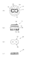
本発明の複数液分配用のエアゾール装置10の一実施の形態では、図1に示すように、エアゾール容器11として一般的に規格品的に用いられている口径1インチのビード部12を備えたインチ缶に2組のエアゾールバルブ15,15を設けて構成してある。
In an embodiment of an
この複数液分配用のエアゾール装置10では、図2,3に示すように、エアゾール容器11のビード部12に合成樹脂製の装着部材13を嵌合装着するようにし、この装着部材13に2組のバルブハウジング装着部14,14が形成してあり、それぞれのバルブハウジング装着部14,14にエアゾールバルブ15,15が装着される。
As shown in FIGS. 2 and 3, in the
この装着部材13は、図4に示すように、略円筒状の外形とされた装着部本体13aを備え、その中間部外周につば部13bが形成されてエアゾール容器11のビード部12上面に当接させることができ、つば部13bの中間部下方にはビード部12の内周に係合させる係合突部13cが形成された係合片13dが円周等間隔に8個設けられ、各係合片13dの上端部と装着部本体13aとの間が放射方向の放射リブ13eで支持され、装着部本体13aとの間に形成された緩衝空間によって弾性変形可能とされ、上方から押し込むことでビード部12に嵌合装着できるようにしてある。
As shown in FIG. 4, the mounting
こうしてエアゾール容器11のビード部12に嵌合装着される装着部材13の装着部本体13aには、上下方向に平行な小円筒状のバルブハウジング装着部14,14が装着部材13の中心軸を挟む両側に設けられ、係合片13dを支持する放射リブ13eを介して装着部本体13a内に支持されるとともに、装着部本体13aの上部に突き出した2つの平側壁面22,22を平行とし、その両端の半円壁面とで略長円形状に形成された先端突出部13f内にバルブハウジング装着部14,14の上端部が配置されている。
Thus, in the mounting portion
このバルブハウジング装着部14,14の中間部内周には、エアゾールバルブ15,15のバルブハウジング16,16を係合固定する係合爪14aが形成してある。
Engaging
これら2組のバルブハウジング装着部14,14に装着されるエアゾールバルブ15,15のバルブハウジング16,16は略円筒状に形成され、その中間部外周に形成した係合段部16aをバルブハウジング装着部14の係合爪14aに係合することで係合固定できるようにしてある。
The valve housings 16, 16 of the
これらバルブハウジング16には、中間上部にそれぞれバルブ室16bが形成されて下端部に形成したチューブ装着部16cにディップチューブ17が連結されており、さらに噴射剤の加圧力で容積を変えることができる内袋18が取り付けられている。
In these
また、各バルブ室16bに装着されるエアゾールバルブ15、15は、ステム15aがステムボディ15bとステム突出部15cとで一体に構成され、ステム突出部15cの中心部に噴射路15dが形成されるとともに、噴射路15dのステムボディ15bの上面に対応する位置にバルブ室16bと連通するオリフィス15eが側方に開口しており、ステム15aおよび一体のステムボディ15bがバルブ室16bの底部に装着したスプリング15fによって上方に付勢されている。そして、各ステム15aは、弁として開閉される環状のステムガスケット15gの中心孔を貫通し、ステム15aが定常位置である上端に付勢された状態では、ステム15aの側方に開口したオリフィス15eを塞いでバルブ室16bと噴射路15dとの連通を遮断し、ステム15aが押し下げられた時にステムガスケット15g自身がたわむことで、オリフィス15eを開いてバルブ室16bとステム15aの噴射路15dとを連通させることができるようになっている。
In addition, the
この弁として開閉されるステムガスケット15gは、周囲がバルブハウジング16の上面および装着部材13の先端突出部13fの上面とに跨るように配置され、バルブハウジング16の上面および装着部材13の先端突出部13fの上面にそれぞれ形成した2重同心上の環状の突起部によるシールポイント16d、13gによりステムガスケット15gを上部から押えた時に面圧を高めてシールできるようにしてある。なお、この実施の形態では、2本のステム15a,15aに対応して一体のステムガスケット15gが用いられ、略長円形状の先端突出部13fの上面形状に対応して形成したもので構成してある。
The
このような装着部材13およびバルブハウジング16,16の外側を覆って金属板製の被覆体19が設けられ、例えばアルミ製とされ、2本のステム15a,15aを貫通させて突出させるとともに、ステムガスケット15gを押えて下端外周をエアゾール容器11のビード部12の外側に固定するようにしている。
A covering
したがって、この被覆体19は、最上部が装着部材13の先端突出部13fの略長円柱形状の外側を覆う形状とされ、その下方に小径円筒部とこれに連続する大径円筒部とクリンプ部とが形成された形状に形成してあり、被覆体19をビード部12に固定する場合には、ビード部12の上面と装着部材13のつば部13bとの間にシールガスケット20を配置してクリンプすることで、エアゾール容器11をシール性を高めて密封できるようにする。
Accordingly, the covering
また、この複数液分配用のエアゾール装置10には、充填作業を円滑に行うとともに、噴射流量を調整するため、バルブハウジング16のバルブ室16bの下方にそれぞれ下部バルブ室16eが形成されてポペットバルブ21が装着してあり、内溶液の充填の際には、ポペットバルブ21を押し下げた位置として周囲を流路とし、短時間に内溶液を充填できるようにする一方、充填後の使用状態では、ポペットバルブ21を内溶液で押し上げた位置に保持することで、中心部の流路で噴射流量を規制できるようにしてある。
Further, in the
したがって、ポペットバルブ21を装着する場合には、ステム15aのオリフィス15eで噴射流量を規制する必要がなく、内溶液の充填に支障のない大きな孔としておくことができる。
Therefore, when the
さらに、この実施の形態の複数液分配用のエアゾール装置10では、被覆体19で2本のステム15a,15aに対応する1つのステムガスケット15gを押えているが、これまでの1本のステムに対応するステムガスケットに比べその面積が先端突出部13fの面積に対応して大きくなりエアゾール容器11の内圧が加わる受圧面積も大きくなることから、ステムガスケット15gを押えるとともに、被覆体19の変形を防止する合成樹脂製の補強カバー部材30が設けてある。
Further, in the
この補強カバー部材30は、図5に示すように、装着部材13の先端突出部13fの外側を覆うカバー部本体30aを備えて構成されており、合成樹脂製の補強カバー部材30の剛性によってステムガスケット15gを押えるとともに、被覆体19の変形を防止するようにしてある。
As shown in FIG. 5, the reinforcing
このような補強カバー部材30を介して被覆体19で押えることで、簡素な部品で受圧面積の増大に対応することができる。
By pressing with the covering
なお、補強カバー部材30としては、この発明の複数液分配用のエアゾル装置の他の実施の形態である図6〜9に示すように、装着部材13の先端突出部13fの外側を覆うカバー本体部30aに加え、カバー本体部30aの下方に連続する装着部材13の装着部本体13aの外側を覆う脚部30bを備えた外形としたもので構成することもできる。この脚部30bを形成することで、この部分を利用して装着部材13に保持する保持手段31を設けることが可能となる。この保持手段31としては、例えば、脚部30bに外周側壁部に保持手段31を構成する横長のスリット31aを円周等間隔に4箇所形成しておき、対応する装着部材13の装着部本体13aに保持用の爪31bを外側に突き出して形成しておく。
In addition, as the reinforcing
このような補強カバー部材30と装着部材13との間に設けた保持手段31のスリット31aと爪31bとを係合して組立状態を保持できるようにすることで、被覆体19で外側を覆ってエアゾール容器11のビード部12に固定する前の状態でもエアゾールバルブ15を組み立てた状態とすることができ、製造・組立を容易にすることができるとともに、固定前の噴射剤の充填作業も簡単に行うことができる。
By engaging the
なお、この複数液分配用のエアゾール装置の他の構成は既に説明した上記実施の形態と同一である。 The other configurations of the aerosol device for distributing multiple liquids are the same as those in the above-described embodiment.
また、補強カバー部材は、被覆体19自体がその材質や板厚などによって受圧面積の増大による変形を防止できる場合には、補強カバー部材30を省略して複数液分配用のエアゾール装置10を構成することもでき、構成部品を減らすことができる。
Further, when the covering 19 itself can be prevented from being deformed due to an increase in pressure receiving area due to its material, plate thickness, etc., the reinforcing
また、装着部材13につば部13bを形成してエアゾール容器11のビード部12上に当接させるようにしたが、つば部を省略して装着部材13の中間部をビード部12に位置させて装着部材13の一部が上方に突き出す状態で被覆体19で覆ってビード部12に固定するようにしても良く、装着部材の形状を単純化でき、金型製作も容易となる。
Moreover, although the
次に、このように構成した複数液分配用のエアゾール装置10の組立手順と内溶液および噴射剤の充填とについて説明する。
Next, the assembly procedure and the filling of the internal solution and propellant of the
まず、装着部材13では、装着部材本体13aのつば部13bの下面にビード部12とのシール用のシールガスケット20を装着しておく。
First, in the mounting
また、バルブハウジング16には、下部バルブ室16eにポペットバルブ21を周囲とは隙間のある状態で装着した後、下端部のチューブ装着部16cにディップチューブ17を接続し、このディップチューブ17を覆うように内袋18を装着し、チューブ装着部16cの外側に固定する。
Further, the
次に、ディップチューブ17および内袋18が固定されたバルブハウジング16を装着部材13のバルブハウジング装着部14に下方から装着し、係合段部16aと係合爪14aを係合させて所定の位置に固定する。
Next, the
また、エアゾールバルブ15は、予めステム15aおよびスプリング15fを組み立てるとともに、ステム15aを貫通させてステムガスケット15gを装着した状態にしておく。
In addition, the
この後、バルブハウジング16のバルブ室16bに予め組み立てられたエアゾールバルブ15を装着し、ステムガスケット15gを装着部材13およびバルブハウジング16の上面に位置させる。
Thereafter, the
こうして2組のエアゾールバルブ15,15を、バルブハウジング16,16を介して装着部材13に装着し、ステムガスケット15gを載せた状態で補強カバー部材30を被せ、ステムガスケット15gを押えるようにする。さらに、この補強カバー部材30の外側を被覆体19で覆い、装着部材13と被覆体19を固定することで、ステムガスケット15gが装着部材13およびバルブハウジング16のシールポイント13g,16dに押圧されてエアゾールバルブ15、15も閉じられた状態となる。
In this way, two sets of
この被覆体19で装着部材13およびバルブハウジング16を覆った状態で、エアゾール容器11の開口部に内袋18,18から挿入するようにしてビード部12につば部12の下面のシールガスケット20が載せ置かれた状態とする。
With the covering
この状態では、エアゾール容器11の開口部から装着した装着部材13の係合片13dの係合突部13cは係合状態とはならず、エアゾール容器11のビード部12と装着部材13との間に隙間が形成された状態となり、エアゾール容器11と外部とが連通状態となっている。
In this state, the
この状態で、エアゾール容器11内に噴射剤の充填が行われる。
In this state, the
噴射剤の充填は、これまでと同様に、被覆体19の外周に噴射剤充填ヘッドを配置し、エアゾール容器11のビード部12と装着部材13との隙間から窒素ガスなどの噴射剤をエアゾール容器11内に充填し、充填の完了と同時に装着部材13を押し込んで係合片13dの係合突部13cを係合状態とし、嵌合装着状態とした後、被覆体19の下端外周のクリンプ部をビード部12の外周にクリンプする。
In the same way as before, the propellant is filled with a propellant filling head on the outer periphery of the covering
この被覆体19をクリンプした状態では、装着部材13のつば部13bの下面のシールガスケット20がビード部12の上面に押圧されてエアゾール容器11が密封状態となるとともに、噴射剤の充填とエアゾール装置10の構成部品の組み立てが完了する。
In the state where the covering 19 is crimped, the
この後、内袋18,18内にステム15a,15aを介して異なる内溶液をそれぞれ分離して充填する。
Thereafter, different inner solutions are separately filled in the
この内溶液の充填の際、これまでのエアゾール容器とは異なり、中心軸を挟む両側に2本のステム15a,15aが位置するとともに、それぞれ異なる内溶液を充填するためには、充填工程においてエアゾール容器11の位置決めを行って所定のステム15a(15a)定めて内溶液の充填を行う必要があるが、装着部材13の先端突出部13fの形状を、平行な平側壁面22、22を備えた略長円形状にしてあるので、平行な平側壁面22、22を利用することで、2本のステム15a,15aを前後あるいは左右などに配置するよう位置決めすることが容易にでき、その状態を保持して所定のステム15a(15a)に充填することで、異なる内溶液を分離してそれぞれの内袋18,18に充填することができる。
When filling the inner solution, unlike the conventional aerosol containers, the two stems 15a and 15a are located on both sides of the central axis, and in order to fill different inner solutions, respectively, The
なお、充填工程におけるエアゾール容器11の位置決めを、装着部材13の先端突出部13fの形状を平行な平側壁面22、22を備えた略長円形状にし、この平行な平側壁面22、22を利用することで、2本のステム15a,15aを前後あるいは左右などに配置するよう位置決めするようにしたが、平行な平側壁面22、22に代えて、図10に示すように、装着部材13の先端突出部13fの形状を平面視8字状とした中央に凹部が形成された曲側壁面23を両側に備えた形状とすることで、これら曲側壁面23、23を利用することで、平行な平側壁面22、22と同様に、2本のステム15a,15aを前後あるいは左右などに配置するよう位置決めすることが容易にでき、その状態を保持して所定のステム15a(15a)に充填することで、異なる内溶液を分離してそれぞれの内袋18,18に充填することができるとともに、曲側壁面23、23の中央凹部を利用して確実に押えることも可能となる。
The positioning of the
なお、この装着部材13を用いる場合には、同図中に示すように、補強カバー部材32を対応する形状にしたものを使用する。
In addition, when using this mounting
また、充填工程におけるエアゾール容器11の位置決めを装着部材13の先端突出部13fの形状を平行な平側壁面22、22としたり、曲側壁面23を両側に形成して利用する場合には、2本のステム15a,15aを前後あるいは左右などに配置するよう位置決めすることができるが、個々のステム15a,15aを特定して位置決めすることはできないことから、図11に示すように、装着部材13の先端突出部13fの形状を一方側の平側壁面22と他方側の中央に凹部が形成された曲側壁面23を備えた形状とすることで、これら平側壁面22と曲側壁面23を利用することで、2本のステム15a,15aを前後あるいは左右などに配置するよう位置決めするだけでなく、それぞれのステム15a,15aを個々に識別して位置決めすることができ、その状態を保持して所定のステム15a(15a)に充填することで、異なる内溶液を分離してそれぞれの内袋18,18に確実に充填することができるとともに、片側の曲側壁面23の中央凹部を利用して確実に押えることも可能となる。
Further, when the
なお、この装着部材13を用いる場合にも、同図中に示すように、補強カバー部材33を対応する形状にしたものを使用する。
Even when the mounting
このような複数液分配用のエアゾール装置10によれば、口径が1インチのビード部12を備えたいわゆるインチ缶であっても2つのエアゾールバルブ15,15を配置することができ、それぞれのエアゾールバルブ15,15のステム15a,15aから内溶液をエアゾール容器11内から外部に分離した状態で混合することなく分配して噴射させることができる。
According to the
これにより、2つの異なる内溶液を外部に分離して混合することなく分配して噴射させることができるエアゾール装置を1インチ缶で構成することができ、エアゾール製品を安価に製造することができる。また、2つのエアゾールバルブによって各内容液を均一な噴射量で噴射させることが可能となる。 Thereby, the aerosol apparatus which can distribute and inject two different internal solutions outside without separating and mixing can be comprised with a 1 inch can, and an aerosol product can be manufactured cheaply. Moreover, it becomes possible to inject each content liquid by the uniform injection amount by two aerosol valves.
さらに、この複数液分配用のエアゾール装置10によれば、エアゾール容器11のビード部12に、装着部材13の中間部を位置させて装着し、ステム15aの挿入部分をビード部12よりも上方に突き出して配置してあるので、2つのエアゾールバルブ15,15の2本のステム15a,15aを並べて配置しても装着部材13の外側から被せる被覆体19によってビード部12の外側に固定することができ、これまでのマウンテンカップのように内側にクリンチ用の空間を確保する必要がなく、口径1インチのビード部12の大きさの拘束を受けることなく、2つのエアゾールバルブ15,15をエアゾール容器11に装着することができる。
Further, according to the
また、1インチのビード部12を備えたインチ缶に装着部材13を介して2つのエアゾールバルブ15,15を配置することで、ステムガスケット15gが2本のステム15a,15aに対応した大きさとなり、ステムガスケット15gを押える被覆体19の天面部の面積が増大し、噴射剤による受圧面積の増大による変形などの恐れがあるが、合成樹脂製の補強カバー部材30をステムガスケット15gと被覆体19との間に設けるようにしたので、被覆体19の変形を防止してステムガスケット15gを押えることができる。
Further, by disposing two
これにより、ステムガスケット15gの変形などによる漏洩を完全に防止することができる。
Thereby, it is possible to completely prevent leakage due to deformation of the
さらに、この複数液分配用のエアゾール装置10によれば、補強カバー部材30と装着部材13との間に、当該補強カバー部材30を当該装着部材13に保持し得る保持手段31を設け、補強カバー部材30の脚部30bにスリット31aを形成し、保持部材13の装着部本体13aに爪31bを形成したので、スリット31aと爪31bを互いに係止することで、補強カバー部材30を装着部材13に組立状態で保持することができる。
Further, according to the
これにより、エアゾールバルブ15,15を組み立てた状態で、被覆体19で覆って固定することができ、スプリング15f,15fで付勢されたステム15a,15aを押えながら組み立てる必要がなく、製造・組立作業が容易となる。
As a result, the
また、この複数液分配用のエアゾール装置10によれば、エアゾールバルブ15,15を2組とし、装着部材13の上端部に2つの平側壁面22、22を平行とした略長円柱形の先端突出部13fを形成し、この先端突出部13fを覆って補強カバー部材30をクリンプして固定するように構成したので、先端突出部13fの平行な平側壁面22、22を基準に組み立てることで位置決めが容易となり、効率的に組立作業を行うことができるとともに、エアゾール容器11に内溶液を充填する充填工程でもそれぞれのステム15a,15aに効率的に作業することができる。さらに、先端突出部13fを平側壁面22と曲側壁面23とを組合わせた形状とすることで、2つのステム15a,15aの位置決めだけでなくそれぞれを識別することも可能となる。
Further, according to the
さらに、この複数液分配用のエアゾール装置10によれば、補強カバー部材30に、先端突出部13fを覆うカバー本体部30aに加えて装着部材13を覆う脚部30bを設けて構成することで、装着部材13の略全体を補強カバー部材30で覆うことができ、一層確実に被覆体19の天面部を補強することができ、内圧による変形や内溶液の漏洩を防止することができる。
Furthermore, according to the
また、この複数液分配用のエアゾール装置10によれば、エアゾール容器11内には噴射剤を充填する一方、2組のエアゾールバルブ15,15にそれぞれ内溶液が充填される容積を可変とする内袋18,18を接続して構成したので、2組それぞれの内溶液を内袋18,18から分離した状態で分配して噴射させることができ、エアゾール容器11の内面と非接触状態で内溶液をそれぞれ噴射させることができる。
In addition, according to the
なお、この複数液分配用のエアゾール装置10では、2本のステムには押しボタン式などのアクチュエータを装着して内溶液を噴射させるが、2つの異なる内溶液をアクチュエータから分離した状態で噴射させるようにしても、アクチュエータ内で混合して噴射させるようにする場合のいずれであっても良く、内溶液の種類やその使用目的などにより適宜選択すれば良い。
In the
また、この複数液分配用のエアゾール装置10の2つの内袋に充填される内溶液としては、主剤と添加剤など予め混合しておくと硬化や酸化などの化学反応を生じて好ましくない剤型のエアゾール製品の主剤と添加剤などを挙げることができ、例えばホットシェービングクリーム、毛髪染料、接着剤、塗料、医薬品などのエアゾール製品として好適であり、さらにフォーム剤形の内溶液にも適用可能である。
In addition, as the inner solution filled in the two inner bags of the
さらに、この複数液分配用のエアゾール装置は、2つの異なる内溶液を充填して分配噴射させる場合に限らず、3つなどさらに複数の異なる内溶液を充填して噴射させるように構成することもできる。 Furthermore, the aerosol device for multi-liquid distribution is not limited to the case where two different internal solutions are filled and distributed and sprayed, and may be configured to be filled and sprayed with a plurality of different internal solutions such as three. it can.
10 複数液分配用のエアゾール装置
11 エアゾール容器(インチ缶)
12 ビード部
13 装着部材
13a 装着部本体
13b つば部
13c 係合突部
13d 係合片
13e 放射リブ
13f 先端突出部
13g シールポイント
14 バルブハウジング装着部
14a 係止爪
15 エアゾールバルブ
15a ステム
15b ステムボディ
15c ステム突出部
15d 噴射路
15e オリフィス
15f スプリング
15g ステムガスケット
16 バルブハウジング
16a 係合段部
16b バルブ室
16c チューブ装着部
16d シールポイント
16e 下部バルブ室
17 ディップチューブ
18 内袋
19 被覆体
20 シールガスケット
21 ポペットバルブ
22 平側壁面
23 曲側壁面
30 補強カバー部材
30a カバー本体部
30b 脚部
31 保持手段
31a スリット
31b 爪
32 補強カバー部材
33 補強カバー部材10 Aerosol device for dispensing
12
Claims (5)
前記開口部に嵌合装着される装着部材に複数のエアゾールバルブを装着し得るバルブハウジング装着部をそれぞれ形成してこれら複数のバルブハウジング装着部のそれぞれにエアゾールバルブを装着するとともに、当該装着部材の中間部を前記ビード部に位置させて装着し、
この装着部材の外側を覆って前記ステムを突出させるとともに、ステムガスケットを押える被覆体を前記ビード部の外側にシールガスケットを介して固定し、前記装着部材と前記被覆体との間には、前記ステムガスケットを押えるとともに、前記被覆体の変形を防止する補強カバー部材を設けたことを特徴とする複数液分配用のエアゾール装置。 For multi-liquid distribution in which a plurality of inner solutions are filled in an aerosol container having a bead portion formed around an opening with a 1-inch diameter, and each content liquid is ejected to the outside through each stem of a plurality of aerosol valves An aerosol device,
A valve housing mounting portion capable of mounting a plurality of aerosol valves is formed on the mounting member fitted and mounted in the opening, and an aerosol valve is mounted on each of the plurality of valve housing mounting portions. Attach the middle part to the bead part,
Covering the outside of the mounting member, the stem protrudes, and a covering body that holds the stem gasket is fixed to the outside of the bead portion via a seal gasket, and between the mounting member and the covering body, An aerosol device for dispensing multiple liquids, characterized in that a reinforcing cover member is provided to hold the stem gasket and prevent deformation of the covering .
Applications Claiming Priority (1)
| Application Number | Priority Date | Filing Date | Title |
|---|---|---|---|
| PCT/JP2010/062154 WO2012011162A1 (en) | 2010-07-20 | 2010-07-20 | Multiple fluid dispensing aerosol device |
Publications (2)
| Publication Number | Publication Date |
|---|---|
| JP5249355B2 true JP5249355B2 (en) | 2013-07-31 |
| JPWO2012011162A1 JPWO2012011162A1 (en) | 2013-09-09 |
Family
ID=45496603
Family Applications (1)
| Application Number | Title | Priority Date | Filing Date |
|---|---|---|---|
| JP2010546131A Active JP5249355B2 (en) | 2010-07-20 | 2010-07-20 | Aerosol device for multi-liquid distribution |
Country Status (8)
| Country | Link |
|---|---|
| US (1) | US9027799B2 (en) |
| EP (1) | EP2597055B1 (en) |
| JP (1) | JP5249355B2 (en) |
| KR (1) | KR101410406B1 (en) |
| CN (1) | CN102985337B (en) |
| ES (1) | ES2551720T3 (en) |
| PT (1) | PT2597055E (en) |
| WO (1) | WO2012011162A1 (en) |
Families Citing this family (17)
| Publication number | Priority date | Publication date | Assignee | Title |
|---|---|---|---|---|
| KR101410408B1 (en) * | 2010-12-02 | 2014-06-20 | 도요 에어로졸 고교 가부시키가이샤 | Multiple liquid dispensing aerosol device |
| JP5992181B2 (en) * | 2012-02-29 | 2016-09-14 | 株式会社ダイゾー | Double container manufacturing method and double aerosol container |
| JP5901564B2 (en) * | 2013-04-03 | 2016-04-13 | 東洋エアゾール工業株式会社 | Fixed plate for aerosol container |
| JP6051107B2 (en) * | 2013-05-31 | 2016-12-27 | 東洋エアゾール工業株式会社 | Aerosol shoulder cover |
| JP6051106B2 (en) * | 2013-05-31 | 2016-12-27 | 東洋エアゾール工業株式会社 | Aerosol shoulder cover |
| EP3006373B1 (en) | 2013-05-31 | 2017-09-06 | Toyo Aerosol Industry Co., Ltd. | Shoulder cover for aerosol container |
| DE102013217024A1 (en) | 2013-08-27 | 2015-03-05 | Henkel Ag & Co. Kgaa | Products in the dispenser for oxidative color change of keratin fibers |
| US10029844B2 (en) * | 2013-12-03 | 2018-07-24 | Mitani Valve Co., Ltd. | Aerosol housing mechanism and aerosol-type product having the aerosol housing mechanism |
| JP6172756B2 (en) * | 2014-04-30 | 2017-08-02 | 株式会社三谷バルブ | Inner and outer double container aerosol injection mechanism and aerosol type product equipped with this inner and outer double container aerosol injection mechanism |
| FR3044644B1 (en) | 2015-12-04 | 2018-01-05 | Oreal | HEAD FOR DISPENSING A COSMETIC COMPOSITION FORMED BY MIXING A FIRST COSMETIC PRODUCT WITH A SECOND COSMETIC PRODUCT, DEVICE AND METHOD THEREOF |
| KR102050344B1 (en) * | 2016-01-18 | 2019-11-29 | 도요 에어로졸 고교 가부시키가이샤 | Fixed plate for aerosol container |
| FR3047425B1 (en) | 2016-02-05 | 2018-03-09 | L'oreal | COSMETIC PRODUCT DISTRIBUTION DEVICE COIFFE, DEVICE AND METHOD THEREOF |
| DE102016012650A1 (en) | 2016-10-24 | 2018-04-26 | Beiersdorf Ag | Mehrkomponentenapplikator |
| DE102016012651A1 (en) | 2016-10-24 | 2018-04-26 | Beiersdorf Ag | Mehrkomponentenapplikator |
| US11466815B2 (en) | 2017-10-06 | 2022-10-11 | Black & Decker Inc. | Hydrogen fuel canister |
| DE102018104238A1 (en) * | 2018-02-26 | 2019-08-29 | Atlas Copco Ias Gmbh | applicator |
| DE102018215090A1 (en) | 2018-09-05 | 2020-03-05 | Novaprot Gmbh | Active cleaner |
Citations (4)
| Publication number | Priority date | Publication date | Assignee | Title |
|---|---|---|---|---|
| JPH0248154U (en) * | 1988-09-27 | 1990-04-03 | ||
| JPH1086983A (en) * | 1996-09-11 | 1998-04-07 | Osaka Ship Building Co Ltd | Two-part mixing type aerosol device |
| JP2002193363A (en) * | 2000-12-22 | 2002-07-10 | Maruichi Valve Co Ltd | Aerosol valve device for plurality of kinds of liquid |
| JP2004244109A (en) * | 2003-01-24 | 2004-09-02 | Toyo Aerosol Ind Co Ltd | Aerosol device for two-liquid delivery |
Family Cites Families (29)
| Publication number | Priority date | Publication date | Assignee | Title |
|---|---|---|---|---|
| US2818202A (en) * | 1953-08-20 | 1957-12-31 | John J Baessler | Glass package dispenser for aerosols |
| US2941696A (en) * | 1957-08-19 | 1960-06-21 | Ortho Pharma Corp | Dispensing container |
| US3092107A (en) * | 1960-02-23 | 1963-06-04 | Nathan D Froot | Hypodermic injection device |
| US3176889A (en) * | 1961-08-14 | 1965-04-06 | Potapenko Gennady | Pressurized dispenser with integral stem seal |
| BE670476A (en) * | 1964-10-09 | 1966-01-31 | ||
| JPS612856Y2 (en) * | 1980-04-10 | 1986-01-29 | ||
| GB8825632D0 (en) * | 1988-11-02 | 1988-12-07 | Bespak Plc | Dispensing apparatus for pressurised dispensing containers |
| US5400920A (en) * | 1993-07-29 | 1995-03-28 | Minnesota Mining And Manufacturing Company | One-time fill aerosol valve |
| DE19541594A1 (en) * | 1995-11-08 | 1997-05-15 | Pfeiffer Erich Gmbh & Co Kg | Discharge unit for media |
| US6736288B1 (en) * | 2000-10-26 | 2004-05-18 | Ronald D. Green | Multi-valve delivery system |
| US5957333A (en) * | 1998-01-26 | 1999-09-28 | Pure Vision International L.L.P. | Aerosol spray container with improved dispensing valve assembly |
| JP3578626B2 (en) * | 1998-04-24 | 2004-10-20 | 東洋エアゾール工業株式会社 | Quantitative valve device for powder aerosol |
| JP2001122364A (en) * | 1999-10-27 | 2001-05-08 | Hoyu Co Ltd | Double walled aerosol container |
| JP2002059985A (en) * | 2000-06-09 | 2002-02-26 | Takeuchi Press Ind Co Ltd | Aerosol container |
| US6691898B2 (en) * | 2002-02-27 | 2004-02-17 | Fomo Products, Inc. | Push button foam dispensing device |
| US8459311B2 (en) * | 2002-06-17 | 2013-06-11 | Ronald D. Green | Multi-valve delivery system |
| JP2004025062A (en) * | 2002-06-26 | 2004-01-29 | Toyo Aerosol Ind Co Ltd | Quantitative jet device for powder aerosol |
| CN2568577Y (en) * | 2002-09-13 | 2003-08-27 | 林添大 | Two-in-on milk bottle |
| JP4148770B2 (en) * | 2002-12-26 | 2008-09-10 | 花王株式会社 | Aerosol container valve mechanism |
| FR2860503B1 (en) * | 2003-10-07 | 2007-11-02 | Valois Sas | VALVE AND DISPENSING DEVICE COMPRISING SUCH A VALVE. |
| US7677420B1 (en) * | 2004-07-02 | 2010-03-16 | Homax Products, Inc. | Aerosol spray texture apparatus for a particulate containing material |
| FR2895374B1 (en) * | 2005-12-27 | 2010-08-27 | Valois Sas | RING FOR AEROSOL VALVE. |
| US7686189B2 (en) * | 2007-01-23 | 2010-03-30 | Conopco, Inc. | Pocket sized fluid dispenser |
| EP2772313A1 (en) * | 2007-03-09 | 2014-09-03 | Kao Corporation | Pump-equipped container and dual discharge container |
| FR2918044B1 (en) * | 2007-06-28 | 2012-01-20 | Valois Sas | RING FOR FLUID PRODUCT DISPENSING VALVE. |
| CN201404880Y (en) * | 2009-05-25 | 2010-02-17 | 杭建平 | Vacuum pump capable of jetting at least two different fillers synchronously |
| FR2946963B1 (en) * | 2009-06-22 | 2015-09-04 | Valois Sas | AEROSOL DOSING VALVE AND FLUID PRODUCT DISPENSING DEVICE COMPRISING SUCH A VALVE |
| DE202010018319U1 (en) * | 2009-12-01 | 2015-07-14 | Toyo Aerosol Industry Co., Ltd. | Aerosol device for arranging a plurality of liquids |
| US8523023B1 (en) * | 2012-07-02 | 2013-09-03 | Donald L. Coroneos | Aerosol container resuscitator |
-
2010
- 2010-07-20 EP EP10854999.9A patent/EP2597055B1/en active Active
- 2010-07-20 JP JP2010546131A patent/JP5249355B2/en active Active
- 2010-07-20 US US13/810,712 patent/US9027799B2/en active Active
- 2010-07-20 ES ES10854999.9T patent/ES2551720T3/en active Active
- 2010-07-20 CN CN201080068130.9A patent/CN102985337B/en active Active
- 2010-07-20 KR KR1020137000121A patent/KR101410406B1/en active IP Right Grant
- 2010-07-20 WO PCT/JP2010/062154 patent/WO2012011162A1/en active Application Filing
- 2010-07-20 PT PT108549999T patent/PT2597055E/en unknown
Patent Citations (4)
| Publication number | Priority date | Publication date | Assignee | Title |
|---|---|---|---|---|
| JPH0248154U (en) * | 1988-09-27 | 1990-04-03 | ||
| JPH1086983A (en) * | 1996-09-11 | 1998-04-07 | Osaka Ship Building Co Ltd | Two-part mixing type aerosol device |
| JP2002193363A (en) * | 2000-12-22 | 2002-07-10 | Maruichi Valve Co Ltd | Aerosol valve device for plurality of kinds of liquid |
| JP2004244109A (en) * | 2003-01-24 | 2004-09-02 | Toyo Aerosol Ind Co Ltd | Aerosol device for two-liquid delivery |
Also Published As
| Publication number | Publication date |
|---|---|
| KR101410406B1 (en) | 2014-06-20 |
| ES2551720T3 (en) | 2015-11-23 |
| EP2597055A4 (en) | 2014-04-09 |
| US9027799B2 (en) | 2015-05-12 |
| KR20130020716A (en) | 2013-02-27 |
| CN102985337A (en) | 2013-03-20 |
| JPWO2012011162A1 (en) | 2013-09-09 |
| WO2012011162A1 (en) | 2012-01-26 |
| US20130112707A1 (en) | 2013-05-09 |
| CN102985337B (en) | 2015-08-26 |
| EP2597055B1 (en) | 2015-09-16 |
| PT2597055E (en) | 2016-01-14 |
| EP2597055A1 (en) | 2013-05-29 |
Similar Documents
| Publication | Publication Date | Title |
|---|---|---|
| JP5249355B2 (en) | Aerosol device for multi-liquid distribution | |
| KR101226572B1 (en) | Aerosol device for allocation of plurality of fluids | |
| WO2012073361A1 (en) | Multiple liquid dispensing aerosol device | |
| US6789702B2 (en) | System for dispensing multi-component products | |
| US7267248B2 (en) | Aerosol dispenser for mixing and dispensing multiple fluid products | |
| US20060048843A1 (en) | Aerosol dispenser for mixing and dispensing multiple fluid products | |
| CN103108813B (en) | Actuator for aerosol container | |
| US20020027146A1 (en) | Dispenser containing a product and dispensing method | |
| US6227417B1 (en) | Pressurized device | |
| US6920904B2 (en) | Device for packaging and dispensing at least two products | |
| US8286840B2 (en) | Fluid product dispensing valve | |
| JP6313947B2 (en) | Multi-content discharge container and method for manufacturing multi-content discharge container | |
| JP2002193363A (en) | Aerosol valve device for plurality of kinds of liquid | |
| US11787619B2 (en) | Valve for pressurized container | |
| JPH10211949A (en) | Pressurizing apparatus having two valves | |
| JP2016508099A (en) | Fluid dispenser | |
| US3439840A (en) | Aerosol dispensing valve for plural sources | |
| JPH09240761A (en) | Valve structure for packaging container | |
| KR101969220B1 (en) | Portable liquid pumping assembly | |
| JP3984033B2 (en) | Pressure vessel seal structure | |
| JPH0295465A (en) | Piston-type aerosol container and its production |
Legal Events
| Date | Code | Title | Description |
|---|---|---|---|
| TRDD | Decision of grant or rejection written | ||
| A01 | Written decision to grant a patent or to grant a registration (utility model) |
Free format text: JAPANESE INTERMEDIATE CODE: A01 Effective date: 20130404 |
|
| A61 | First payment of annual fees (during grant procedure) |
Free format text: JAPANESE INTERMEDIATE CODE: A61 Effective date: 20130411 |
|
| R150 | Certificate of patent or registration of utility model |
Free format text: JAPANESE INTERMEDIATE CODE: R150 Ref document number: 5249355 Country of ref document: JP Free format text: JAPANESE INTERMEDIATE CODE: R150 |
|
| FPAY | Renewal fee payment (event date is renewal date of database) |
Free format text: PAYMENT UNTIL: 20160419 Year of fee payment: 3 |
|
| R250 | Receipt of annual fees |
Free format text: JAPANESE INTERMEDIATE CODE: R250 |
|
| R250 | Receipt of annual fees |
Free format text: JAPANESE INTERMEDIATE CODE: R250 |
|
| R250 | Receipt of annual fees |
Free format text: JAPANESE INTERMEDIATE CODE: R250 |
|
| R250 | Receipt of annual fees |
Free format text: JAPANESE INTERMEDIATE CODE: R250 |
|
| R250 | Receipt of annual fees |
Free format text: JAPANESE INTERMEDIATE CODE: R250 |
|
| R250 | Receipt of annual fees |
Free format text: JAPANESE INTERMEDIATE CODE: R250 |
|
| R250 | Receipt of annual fees |
Free format text: JAPANESE INTERMEDIATE CODE: R250 |
|
| R250 | Receipt of annual fees |
Free format text: JAPANESE INTERMEDIATE CODE: R250 |
|
| R250 | Receipt of annual fees |
Free format text: JAPANESE INTERMEDIATE CODE: R250 |