JP5248973B2 - Temperature measuring device - Google Patents
Temperature measuring device Download PDFInfo
- Publication number
- JP5248973B2 JP5248973B2 JP2008265929A JP2008265929A JP5248973B2 JP 5248973 B2 JP5248973 B2 JP 5248973B2 JP 2008265929 A JP2008265929 A JP 2008265929A JP 2008265929 A JP2008265929 A JP 2008265929A JP 5248973 B2 JP5248973 B2 JP 5248973B2
- Authority
- JP
- Japan
- Prior art keywords
- temperature
- calibration device
- temperature sensor
- powered
- sensor
- Prior art date
- Legal status (The legal status is an assumption and is not a legal conclusion. Google has not performed a legal analysis and makes no representation as to the accuracy of the status listed.)
- Active
Links
Images


Description
本発明は、無給電温度センサを用いて被測定物の温度を測定するとともに、前記無給電温度センサに応じて前記温度算出校正装置を校正する温度測定装置に関する。 The present invention relates to a temperature measurement device that measures the temperature of an object to be measured using a non-powered temperature sensor and calibrates the temperature calculation calibration device according to the non-powered temperature sensor.
近年、被測定物の温度を、電力を供給せずに無線で送信することができる無給電温度センサが注目されている。この無給電温度センサとしては一般的には、SAWセンサが用いられている(特許文献1参照)。 In recent years, a non-powered temperature sensor that can wirelessly transmit the temperature of an object to be measured without supplying electric power has attracted attention. In general, a SAW sensor is used as the non-powered temperature sensor (see Patent Document 1).
特許文献1では、遠隔計測する基地局からバースト波が送信され、SAWセンサが備えるアンテナで前記バースト波が受信され、SAWセンサ内の櫛形電極によって弾性表面波が励振され、他の櫛形電極を経て前記アンテナから電磁波として放射される。SAWセンサでは、前記弾性表面波の伝搬速度は温度によって異なるために、前記基地局から送信されたバースト波と、前記基地局で受信する前記電磁波との位相差(時間差)に基づいて被測定物の温度を測定することができる。 In Patent Document 1, a burst wave is transmitted from a base station to be remotely measured, the burst wave is received by an antenna provided in the SAW sensor, a surface acoustic wave is excited by a comb electrode in the SAW sensor, and passes through another comb electrode. Radiated as electromagnetic waves from the antenna. In the SAW sensor, since the propagation speed of the surface acoustic wave varies depending on the temperature, the object to be measured is based on the phase difference (time difference) between the burst wave transmitted from the base station and the electromagnetic wave received by the base station. Temperature can be measured.
しかしながら、SAWセンサを長期間使用していると経時変化により、同じ温度に対しても、前記電磁波の位相差が異なり、被測定物の温度を正確に測定できなくなる場合がある。 However, if the SAW sensor is used for a long time, the phase difference of the electromagnetic wave is different even at the same temperature due to a change with time, and the temperature of the object to be measured may not be measured accurately.
本発明は、上記の課題を考慮してなされたものであって、無給電温度センサに経時変化があっても、被測定物の温度の測定誤差の発生を防ぐことが可能となる温度測定装置を提供することを目的とする。 The present invention has been made in consideration of the above-described problem, and is a temperature measuring device that can prevent the occurrence of a measurement error in the temperature of an object to be measured even when the non-powered temperature sensor changes with time. The purpose is to provide.
本発明に係る温度測定装置は、被測定物の温度に対応した信号を出力する無給電温度センサと、前記無給電温度センサからの出力信号に基づいて自身の温度を校正することにより、前記被測定物の温度を補正するための校正データを求める温度算出校正装置と、を備え、前記無給電温度センサは、前記被測定物の温度に対応した出力信号を前記温度算出校正装置に無線で送信し、前記温度算出校正装置は、前記被測定物の温度に対応した出力信号及び前記校正データに基づいて被測定物の温度を算出し、前記被測定物の温度に対応した出力信号の電界強度が閾値以上の場合に、前記無給電温度センサが前記温度算出校正装置に載置されたと判断し、前記無給電温度センサの出力信号に基づいて前記温度算出校正装置の温度を校正し、前記校正データを求めることを特徴とする。 Temperature measurement apparatus according to the present invention, and the parasitic temperature sensor for outputting a signal corresponding to the temperature of the object to be measured, by calibrating their temperature based on the output signal from the passive temperature sensors, the object and a temperature calculation calibration device asking you to calibration data for correcting the temperature of the measured object, the passive temperature sensor, a wireless output signal corresponding to the temperature of the object to be measured to the temperature calculating calibration device The temperature calculation calibration device calculates the temperature of the measurement object based on the output signal corresponding to the temperature of the measurement object and the calibration data , and the electric field of the output signal corresponding to the temperature of the measurement object When the intensity is greater than or equal to a threshold, it is determined that the non-feed temperature sensor is placed on the temperature calculation calibration device, and the temperature of the temperature calculation calibration device is calibrated based on the output signal of the non-feed temperature sensor , Proofreading And wherein the Rukoto asked for over data.
温度測定装置では、温度算出校正装置が、前記被測定物の温度に対応した出力信号の電界強度が閾値以上の場合に、前記無給電温度センサが前記温度算出校正装置に載置されたと判断し、前記無給電温度センサに応じて校正されることにより、無給電温度センサの経時変化による温度測定の誤差の発生を防ぐことができる。また、無給電温度センサによって被測定物の温度を測定する者は、意識せずに無給電温度センサに応じた温度算出校正装置の校正をすることができる。 In the temperature measurement device, the temperature calculation calibration device determines that the non-powered temperature sensor is placed on the temperature calculation calibration device when the electric field strength of the output signal corresponding to the temperature of the object to be measured is greater than or equal to a threshold value. By calibrating according to the non-powered temperature sensor, it is possible to prevent the temperature measurement error from occurring due to the time-dependent change of the non-powered temperature sensor. Further, a person who measures the temperature of the object to be measured by the non-powered temperature sensor can calibrate the temperature calculation calibration device corresponding to the non-powered temperature sensor without being conscious of it.
また、前記温度算出校正装置の校正は、前記温度算出校正装置に設けられた温度センサによって測定された前記温度算出校正装置の温度と、載置された前記無給電温度センサによって算出された前記温度算出校正装置の温度とに基づいて行ってもよい。 In addition, the calibration of the temperature calculation calibration device is performed by measuring the temperature of the temperature calculation calibration device measured by a temperature sensor provided in the temperature calculation calibration device and the temperature calculated by the non-powered temperature sensor placed on the temperature calculation calibration device. You may perform based on the temperature of a calculation calibration apparatus.
さらに、前記温度算出校正装置は、算出した前記被測定物の温度を記録し、記録した前記被測定物の温度に基づいて前記被測定物の温度変化を表示部に表示してもよい。 Further, the temperature calculation / calibration apparatus may record the calculated temperature of the object to be measured, and display a temperature change of the object to be measured on a display unit based on the recorded temperature of the object to be measured.
さらにまた、前記無給電温度センサは、弾性表面波素子であることが好ましい。 Furthermore, the non-powered temperature sensor is preferably a surface acoustic wave element.
本発明によれば、温度測定装置では、被測定物の温度に対応した出力信号の電界強度が閾値以上の場合に、無給電温度センサが温度算出校正装置に載置されたと判断し、前記無給電温度センサからの出力信号に基づいて前記温度算出校正装置を校正することにより、無給電温度センサの経時変化による温度測定の誤差の発生を防ぐことができる。また、無給電温度センサによって被測定物の温度を測定する者は、意識せずに無給電温度センサに応じた温度算出校正装置の校正をすることができる。 According to the present invention, the temperature measuring device determines that the non-powered temperature sensor is placed on the temperature calculation calibration device when the electric field strength of the output signal corresponding to the temperature of the object to be measured is greater than or equal to the threshold value. By calibrating the temperature calculation / calibration device based on the output signal from the power supply temperature sensor, it is possible to prevent the temperature measurement error from occurring due to the time-dependent change of the non-power supply temperature sensor. Further, a person who measures the temperature of the object to be measured by the non-powered temperature sensor can calibrate the temperature calculation calibration device corresponding to the non-powered temperature sensor without being conscious of it.
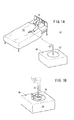
以下、本発明の実施形態について図面を参照して説明する。図1Aは、本発明の実施形態に係る温度測定装置10の全体の説明図であり、図1Bは、無給電温度センサ20に基づく温度算出校正装置40の校正の説明図であり、図2は、無給電温度センサ20の構成、温度算出校正装置40の構成の説明図であり、図3は、患者32の温度を算出するために用いる位相差と温度との関係を示す図である。
Embodiments of the present invention will be described below with reference to the drawings. FIG. 1A is an explanatory diagram of the entire
温度測定装置10は、無給電温度センサ20と、温度算出校正装置40とを備え、無給電温度センサ20と温度算出校正装置40間は無線通信される。無給電温度センサ20は、温度算出校正装置40から放射されるバースト波を受信するためのアンテナ22と、弾性表面波素子24とを備える。
The
弾性表面波素子24は、櫛形電極26と、反射器28とを備え、これらは圧電基板30上に形成される。櫛形電極26は、アンテナ22で受信したバースト波に基づいて、弾性表面波を励振させるため電極である。反射器28は、圧電基板30上に櫛形電極26から出力される弾性表面波の伝搬方向に対して垂直な方向に延在するように金属膜を蒸着して形成した複数の凸部で構成される。圧電基板30は、弾性表面波を伝搬することができれば、特に限られないが、36度Y板X伝搬LiTaO3であることが好ましい。
The surface
温度算出校正装置40は、アンテナ42と、バースト波を無給電温度センサ20に対して送信する送信部44と、無給電温度センサ20からの信号を受信する受信部46と、送信部44からの送信、受信部46での受信の際のアンテナ42を共用するための送受波器48と、送信部44から送信された送信信号と受信部46で受信された受信信号との位相差(時間差)φを検出する位相差検出部50と、前記受信信号の電界強度Eを検出する電界強度検出部52と、患者(被測定物)32の温度の算出や位相差検出部50で検出された位相差の補正等をする制御部54と、患者32の温度を記録するメモリ56と、患者32の温度(体温)を表示する表示器58と、温度算出校正装置40の温度校正のために用いる温度センサ60とを備える。
The temperature
アンテナ42は、電界強度のことを考慮して、温度算出校正装置40の筐体の上面中心部に設けられることが好ましく、また、アンテナ42が設けられた位置を中心とした校正領域62に無給電温度センサ20が載置される。
The
送受波器48は、送信部44からの送信信号が受信部46に回り込むのを防ぐために、信号の送信時と受信時にスイッチで切り換えるように構成されている。
The transmitter /
制御部54は、位相差検出部50で検出された送信部44からの送信信号と、受信部46での受信信号との位相差に基づいて患者32の温度を算出する。患者32の温度の算出は、制御部54内に予め用意されている前記位相差と温度との関係を利用して行われる。例えば、図3に示すように位相差と温度との関係を示す図を利用し、検出した前記位相差φに基づいて患者32の温度を求めることができる。また、制御部54は、電界強度検出部52から出力された受信信号の電界強度Eと、予め設定された電界強度の閾値Ethとを比較する。電界強度Eが、閾値Ethよりも大きい場合には無給電温度センサ20が温度算出校正装置40に載置されたと判断して無給電温度センサ20からの出力信号に基づいて温度算出校正装置40の温度の校正を開始する。電界強度Eが、閾値Ethよりも小さい場合には制御部54によって、患者32の温度が算出される。
The
なお、閾値Ethは、無給電温度センサ20を温度算出校正装置40の校正領域62に載置した場合に、送信部44からバースト波を送信して、無給電温度センサ20で受信された後に、無給電温度センサ20から温度算出校正装置40に送信された信号の電界強度よりもやや小さい値に設定される。また、無給電温度センサ20で算出された患者32の温度はメモリ56に記録可能であり、記録された患者32の温度を表示器58に表示させたり、統計的な処理をした結果を表示器58に表示することもできる。
Note that the threshold Eth is transmitted after a burst wave is transmitted from the
温度測定装置10を用いた患者32の温度の測定、無給電温度センサ20からの出力信号に基づく温度算出校正装置40の校正は、以下のように行われる。
Measurement of the temperature of the
まず、無給電温度センサ20の出力信号に基づいた温度算出校正装置40の温度の校正が行われる。この校正のために、無給電温度センサ20が温度算出校正装置40の校正領域62に載置される(図1B参照)。次いで、送信部44でバースト波が発生され、送受波器48を介してアンテナ42から送信されると同時に、送信部44からは位相差検出部50にもバースト波が送信される。
First, the temperature of the temperature
送信されたバースト波は、無給電温度センサ20のアンテナ22によって受信される。受信されたバースト波は櫛形電極26で励振されて弾性表面波として圧電基板30上を伝搬して、反射器28で反射されて、櫛形電極26に到達する。櫛形電極26に到達した弾性表面波は、アンテナ22で電波に変換されて、検出信号として温度算出校正装置40に対して送信される。前記検出信号は、無給電温度センサ20によって検出され温度算出校正装置40で算出される温度に対応した信号である。
The transmitted burst wave is received by the
前記検出信号は、温度算出校正装置40のアンテナ42、送受波器48を経て、受信部46で受信されて、位相差検出部50と電界強度検出部52とに出力される。位相差検出部50では、送信部44から送信されたバースト波と、前記検出信号との位相差φ0が検出されて制御部54に出力される。また、電界強度検出部52では、受信部46から出力された検出信号の電界強度Eが検出されて制御部54に出力される。
The detection signal is received by the
制御部54では、電界強度Eと閾値Ethとが比較され、無給電温度センサ20が温度算出校正装置40に載置されている場合には、電界強度Eは閾値Ethよりも大きいために温度算出校正装置40の温度校正がされる。温度算出校正装置40の温度校正は、温度センサ60によって測定された温度算出校正装置40自身の温度t0が制御部54に出力され、図3に示すような位相差と温度の関係からこの温度t0に対する位相差φt0が読み出される。この位相差φt0と、検出信号の位相差φ0との差分Δφ(=φ0−φt0)が校正データとして制御部54内に記憶される。以後の無給電温度センサ20による患者32の温度の測定では、無給電温度センサ20からの検出信号の位相差φを校正データΔφで補正した位相差に基づいて患者32の温度が制御部54によって算出される。
In the
温度算出校正装置40の校正後、患者32に無給電温度センサ20が設置され(図1B参照)、患者32の温度の測定が開始される。患者32の温度の測定は、上述した温度算出校正装置40の温度校正と同様に、送信部44からバースト波が送信され、無給電温度センサ20で受信された後に、櫛形電極26で励振されて弾性表面波として圧電基板30上を伝搬して、反射器28で反射されて、櫛形電極26に到達する。櫛形電極26に到達した弾性表面波は、アンテナ22で電波に変換されて検出信号として温度算出校正装置40に対して送信される。
After calibration of the temperature
前記検出信号は、アンテナ42、送受波器48を経て、受信部46で受信されて、位相差検出部50と電界強度検出部52とに出力される。位相差検出部50では、送信部44から送信されたバースト波と、前記検出信号との位相差φが検出されて制御部54に出力される。また、電界強度検出部52では、受信部46から出力された検出信号の電界強度Eが検出されて制御部54に出力される。
The detection signal is received by the
制御部54では、電界強度Eと閾値Ethが比較され、患者32に無給電温度センサ20が取り付けられている場合には、電界強度Eは閾値Ethよりも小さいために、制御部54による患者32の温度が求められる。患者32の温度は、位相差φを校正データΔφで補正した位相差と、図3に示すような位相差と温度の関係から求められる。
In the
求められた温度は、メモリ56に記録されるとともに、表示器58にも出力されて、患者32の温度が表示される。
The obtained temperature is recorded in the
無給電温度センサ20を使用していると経時変化により、検出信号の特性が変化し、測定温度に誤差が生じる場合があり、この測定誤差の発生を防ぐために温度算出校正装置40の温度校正が必要となる。
When the
温度算出校正装置40の温度校正は、上述した患者32の温度の測定前の温度校正と同様に、無給電温度センサ20を温度算出校正装置40の校正領域62に載置することにより行われる。この校正により、患者32の温度の測定前の校正データが更新されて校正データΔφ’となる。以後の無給電温度センサ20による患者32の温度の測定では、無給電温度センサ20からの検出信号の位相差φを校正データΔφ’で補正した位相差に基づいて図3に示すような位相差と温度の関係より患者32の温度が制御部54によって求められる。
The temperature calibration of the temperature
以上説明したように、本発明の実施形態に係る温度測定装置10は、患者32の温度に対応した信号を出力する無給電温度センサ20と、無給電温度センサ20からの出力信号に基づいて校正される温度算出校正装置40とを備え、無給電温度センサ20は、患者32の温度に対応した出力信号を温度算出校正装置40に無線で送信し、温度算出校正装置40は、前記患者32の温度に対応した出力信号に基づいて患者32の温度を算出し、患者32の温度に対応した出力信号の電界強度が閾値以上の場合に、無給電温度センサ20が温度算出校正装置40に載置されたと判断し、無給電温度センサ20の出力信号に基づいて校正される。
As described above, the
このようにして、温度算出校正装置40が校正されることにより、無給電温度センサ20の経時変化による温度測定の誤差の発生を防ぐことができる。また、無給電温度センサ20によって患者32の温度を測定する者は、意識せずに無給電温度センサ20に応じた温度算出校正装置40の校正をすることができる。
In this way, the temperature
また、温度算出校正装置40の校正は、温度算出校正装置40に設けられた温度センサ60によって測定された温度算出校正装置40の温度と、載置された無給電温度センサ20によって算出された温度算出校正装置40の温度とに基づいて行われる。
Further, the calibration of the temperature
さらに、温度測定装置10では、温度算出校正装置40内のメモリ56に算出した患者32の温度を記録することにより、この記録した患者32の温度に基づいて患者32の温度変化を表示器58に表示することにより、体調管理を効率的に行うこともできる。
Further, the
さらにまた、送信部44から周波数の異なるバースト波を送信することにより、患者32に複数の無給電温度センサ20を設置して、多面的に患者32の温度を測定することができる。
Furthermore, by transmitting burst waves having different frequencies from the
また、電界強度検出部52で検出された検出信号の電界強度が閾値Ethを超えた場合には、温度算出校正装置40の表示器58に校正中である旨を文字で表示したり、LED等を点灯するようにしてもよい。さらに、制御部54に閾値Ethの他に閾値Ethよりも大きな閾値Exを設定して、前記検出信号の電界強度と比較し、前記検出信号の電界強度が閾値Exよりも大きい場合や、無給電温度センサ20が温度算出校正装置40に載置されているにも拘わらず、検出信号の電界強度が閾値Ethを超えない場合には、無給電温度センサ20が故障している旨を文字で表示したり、文字の表示又はLED等の点灯をさせないことにより無給電温度センサ20が故障していると判断するようにしてもよい。
Further, when the electric field intensity of the detection signal detected by the electric field
さらに、図1Aでは、患者32として患者が対象であったが、これに限定されるものではなく、温度を測定することが可能なもののすべてが対象となる。また、図1Bでは、無給電温度センサ20はリストバントに設けられているが、無給電温度センサ20が設けられる対象はこれに限定されるものではなく、患者32に応じて適宜、変更することができる。
Further, in FIG. 1A, the patient is the target as the
また、本発明は、上述の実施形態に限らず、本発明の要旨を逸脱することなく、種々の構成を採り得ることはもちろんである。 In addition, the present invention is not limited to the above-described embodiment, and it is needless to say that various configurations can be adopted without departing from the gist of the present invention.
10…温度測定装置 20…無給電温度センサ
22、42…アンテナ 24…弾性表面波素子
26…櫛形電極 28…反射器
30…圧電基板 32…患者
40…温度算出校正装置 44…送信部
46…受信部 48…送受波器
50…位相差検出部 52…電界強度検出部
54…制御部 56…メモリ
58…表示器 60…温度センサ
62…校正領域
DESCRIPTION OF
Claims (4)
前記無給電温度センサからの出力信号に基づいて自身の温度を校正することにより、前記被測定物の温度を補正するための校正データを求める温度算出校正装置と、
を備え、
前記無給電温度センサは、前記被測定物の温度に対応した出力信号を前記温度算出校正装置に無線で送信し、
前記温度算出校正装置は、前記被測定物の温度に対応した出力信号及び前記校正データに基づいて被測定物の温度を算出し、前記被測定物の温度に対応した出力信号の電界強度が閾値以上の場合に、前記無給電温度センサが前記温度算出校正装置に載置されたと判断し、前記無給電温度センサの出力信号に基づいて前記温度算出校正装置の温度を校正し、前記校正データを求める
ことを特徴とする温度測定装置。 A non-powered temperature sensor that outputs a signal corresponding to the temperature of the object to be measured;
Wherein by calibrating their temperature based on the output signal from the parasitic temperature sensor, and temperature calculation calibration device asking you to calibration data for correcting the temperature of the object to be measured,
With
The non-powered temperature sensor wirelessly transmits an output signal corresponding to the temperature of the object to be measured to the temperature calculation calibration device,
The temperature calculation calibration device calculates the temperature of the measurement object based on the output signal corresponding to the temperature of the measurement object and the calibration data , and the electric field strength of the output signal corresponding to the temperature of the measurement object is a threshold value. In the above case, it is determined that the non-feed temperature sensor is placed on the temperature calculation calibration device, the temperature of the temperature calculation calibration device is calibrated based on the output signal of the non-feed temperature sensor, and the calibration data is temperature measurement apparatus characterized by Ru determined.
前記温度算出校正装置の校正は、前記温度算出校正装置に設けられた温度センサによって測定された前記温度算出校正装置の温度と、前記温度算出校正装置に載置された前記無給電温度センサによって算出された前記温度算出校正装置の温度とに基づいて行われる
ことを特徴とする温度測定装置。 The temperature measuring device according to claim 1,
The calibration of the temperature calculation calibration device is calculated by the temperature of the temperature calculation calibration device measured by the temperature sensor provided in the temperature calculation calibration device and the non-powered temperature sensor mounted on the temperature calculation calibration device. The temperature measurement device is performed based on the temperature of the temperature calculation calibration device.
前記温度算出校正装置は、算出した前記被測定物の温度を記録し、記録した前記被測定物の温度に基づいて前記被測定物の温度変化を表示部に表示する
ことを特徴とする温度測定装置。 The temperature measuring device according to claim 1 or 2,
The temperature calculation calibration device records the calculated temperature of the measurement object, and displays a temperature change of the measurement object on a display unit based on the recorded temperature of the measurement object. apparatus.
前記無給電温度センサは、弾性表面波素子から構成される
ことを特徴とする温度測定装置。 In the temperature measuring device according to any one of claims 1 to 3,
The non-power-feeding temperature sensor is composed of a surface acoustic wave element.
Priority Applications (1)
| Application Number | Priority Date | Filing Date | Title |
|---|---|---|---|
| JP2008265929A JP5248973B2 (en) | 2008-10-15 | 2008-10-15 | Temperature measuring device |
Applications Claiming Priority (1)
| Application Number | Priority Date | Filing Date | Title |
|---|---|---|---|
| JP2008265929A JP5248973B2 (en) | 2008-10-15 | 2008-10-15 | Temperature measuring device |
Publications (2)
| Publication Number | Publication Date |
|---|---|
| JP2010096558A JP2010096558A (en) | 2010-04-30 |
| JP5248973B2 true JP5248973B2 (en) | 2013-07-31 |
Family
ID=42258357
Family Applications (1)
| Application Number | Title | Priority Date | Filing Date |
|---|---|---|---|
| JP2008265929A Active JP5248973B2 (en) | 2008-10-15 | 2008-10-15 | Temperature measuring device |
Country Status (1)
| Country | Link |
|---|---|
| JP (1) | JP5248973B2 (en) |
Families Citing this family (3)
| Publication number | Priority date | Publication date | Assignee | Title |
|---|---|---|---|---|
| JP5786533B2 (en) * | 2010-09-24 | 2015-09-30 | 株式会社村田製作所 | Wireless thermometer and wireless thermometer measurement system |
| DE102013220035A1 (en) * | 2013-10-02 | 2015-04-02 | Meiko Maschinenbau Gmbh & Co. Kg | Method for calibrating a cleaning device |
| CN110196075B (en) * | 2018-02-27 | 2022-02-08 | 上海市计量测试技术研究院 | Remote temperature and humidity testing method for environmental test equipment calibration |
Family Cites Families (2)
| Publication number | Priority date | Publication date | Assignee | Title |
|---|---|---|---|---|
| JPS6046434A (en) * | 1983-08-25 | 1985-03-13 | Toshiba Corp | Temperature detector |
| JP2008175678A (en) * | 2007-01-18 | 2008-07-31 | Nec Tokin Corp | Dynamic quantity sensor system |
-
2008
- 2008-10-15 JP JP2008265929A patent/JP5248973B2/en active Active
Also Published As
| Publication number | Publication date |
|---|---|
| JP2010096558A (en) | 2010-04-30 |
Similar Documents
| Publication | Publication Date | Title |
|---|---|---|
| US6547745B1 (en) | Fever alarm system | |
| US7810992B2 (en) | Non-contact temperature-measuring device and the method thereof | |
| US20180032161A1 (en) | Pen, distance measurement method and distance measurement device | |
| EP2045590B1 (en) | Method and apparatus for non-contact temperature measurement | |
| US20090299682A1 (en) | Surface temperature profile | |
| JP5248973B2 (en) | Temperature measuring device | |
| JP5730008B2 (en) | Underwater position detection system, ship-side receiver, and underwater position detection method | |
| US20140046199A1 (en) | Method for measuring human vital signs and portable terminal adopting the same | |
| JP2013195211A (en) | Ultrasonic sensor and calibration method of the same | |
| US20040122609A1 (en) | Gravity corrected scale, gravity correction indicator and gravity corrected scale system | |
| JP6832152B2 (en) | Gas concentration measuring device and its calibration method | |
| JP2011087841A (en) | Ultrasonic diagnosis device | |
| US11294051B2 (en) | Ultrasonic measurement device | |
| EP1785701A1 (en) | Apparatus and method for determining a temperature of a volume of gas | |
| JP2013195112A (en) | Acoustic wave sensor | |
| JP2011179900A (en) | Electronic clinical thermometer | |
| KR20090040699A (en) | Extension apparatus for measurement range of ultrasonic thickness gage | |
| JP2020046257A (en) | Wireless temperature measuring system | |
| EP4227202A1 (en) | Draft information generating device and draft information generating method | |
| JPH08334321A (en) | Ultrasonic distance-measuring apparatus | |
| WO2018131361A1 (en) | Measurement device, measurement method, and program | |
| US20100087751A1 (en) | Acoustic reflectometry instrument and method | |
| JP2004309144A (en) | Measuring instrument and measuring system | |
| KR20220163178A (en) | Temperature Detecting System for a Feeding Bottle and Human Body | |
| JPH1144759A (en) | Ultrasonic distance measuring device and distance measuring method using ultrasonic wave |
Legal Events
| Date | Code | Title | Description |
|---|---|---|---|
| A621 | Written request for application examination |
Free format text: JAPANESE INTERMEDIATE CODE: A621 Effective date: 20111012 |
|
| A977 | Report on retrieval |
Free format text: JAPANESE INTERMEDIATE CODE: A971007 Effective date: 20130115 |
|
| A131 | Notification of reasons for refusal |
Free format text: JAPANESE INTERMEDIATE CODE: A131 Effective date: 20130122 |
|
| A521 | Written amendment |
Free format text: JAPANESE INTERMEDIATE CODE: A523 Effective date: 20130325 |
|
| TRDD | Decision of grant or rejection written | ||
| A01 | Written decision to grant a patent or to grant a registration (utility model) |
Free format text: JAPANESE INTERMEDIATE CODE: A01 Effective date: 20130409 |
|
| A61 | First payment of annual fees (during grant procedure) |
Free format text: JAPANESE INTERMEDIATE CODE: A61 Effective date: 20130411 |
|
| R150 | Certificate of patent or registration of utility model |
Ref document number: 5248973 Country of ref document: JP Free format text: JAPANESE INTERMEDIATE CODE: R150 Free format text: JAPANESE INTERMEDIATE CODE: R150 |
|
| FPAY | Renewal fee payment (event date is renewal date of database) |
Free format text: PAYMENT UNTIL: 20160419 Year of fee payment: 3 |