JP5248088B2 - Monitor panel mounting structure - Google Patents
Monitor panel mounting structure Download PDFInfo
- Publication number
- JP5248088B2 JP5248088B2 JP2007301621A JP2007301621A JP5248088B2 JP 5248088 B2 JP5248088 B2 JP 5248088B2 JP 2007301621 A JP2007301621 A JP 2007301621A JP 2007301621 A JP2007301621 A JP 2007301621A JP 5248088 B2 JP5248088 B2 JP 5248088B2
- Authority
- JP
- Japan
- Prior art keywords
- monitor panel
- seat
- frame member
- pad member
- frame
- Prior art date
- Legal status (The legal status is an assumption and is not a legal conclusion. Google has not performed a legal analysis and makes no representation as to the accuracy of the status listed.)
- Active
Links
- 239000000463 material Substances 0.000 claims description 39
- 229920005989 resin Polymers 0.000 description 11
- 239000011347 resin Substances 0.000 description 11
- 229910052751 metal Inorganic materials 0.000 description 6
- 239000002184 metal Substances 0.000 description 6
- 238000000034 method Methods 0.000 description 3
- 230000002093 peripheral effect Effects 0.000 description 3
- -1 polypropylene Polymers 0.000 description 3
- 238000003825 pressing Methods 0.000 description 3
- 230000037303 wrinkles Effects 0.000 description 3
- 229920001971 elastomer Polymers 0.000 description 2
- RTZKZFJDLAIYFH-UHFFFAOYSA-N ether Substances CCOCC RTZKZFJDLAIYFH-UHFFFAOYSA-N 0.000 description 2
- 238000005187 foaming Methods 0.000 description 2
- 230000013011 mating Effects 0.000 description 2
- 238000009958 sewing Methods 0.000 description 2
- 229920001187 thermosetting polymer Polymers 0.000 description 2
- JOYRKODLDBILNP-UHFFFAOYSA-N Ethyl urethane Chemical compound CCOC(N)=O JOYRKODLDBILNP-UHFFFAOYSA-N 0.000 description 1
- FYYHWMGAXLPEAU-UHFFFAOYSA-N Magnesium Chemical compound [Mg] FYYHWMGAXLPEAU-UHFFFAOYSA-N 0.000 description 1
- 229920000877 Melamine resin Polymers 0.000 description 1
- 239000004677 Nylon Substances 0.000 description 1
- 239000004743 Polypropylene Substances 0.000 description 1
- UCKMPCXJQFINFW-UHFFFAOYSA-N Sulphide Chemical compound [S-2] UCKMPCXJQFINFW-UHFFFAOYSA-N 0.000 description 1
- 229920001807 Urea-formaldehyde Polymers 0.000 description 1
- 239000000853 adhesive Substances 0.000 description 1
- 230000001070 adhesive effect Effects 0.000 description 1
- 229920000180 alkyd Polymers 0.000 description 1
- 239000000806 elastomer Substances 0.000 description 1
- 239000003822 epoxy resin Substances 0.000 description 1
- 230000004927 fusion Effects 0.000 description 1
- LNEPOXFFQSENCJ-UHFFFAOYSA-N haloperidol Chemical compound C1CC(O)(C=2C=CC(Cl)=CC=2)CCN1CCCC(=O)C1=CC=C(F)C=C1 LNEPOXFFQSENCJ-UHFFFAOYSA-N 0.000 description 1
- 238000009434 installation Methods 0.000 description 1
- 239000004973 liquid crystal related substance Substances 0.000 description 1
- 229910052749 magnesium Inorganic materials 0.000 description 1
- 239000011777 magnesium Substances 0.000 description 1
- 229920001778 nylon Polymers 0.000 description 1
- 239000005011 phenolic resin Substances 0.000 description 1
- 229920001123 polycyclohexylenedimethylene terephthalate Polymers 0.000 description 1
- 229920000647 polyepoxide Polymers 0.000 description 1
- 229920001225 polyester resin Polymers 0.000 description 1
- 239000004645 polyester resin Substances 0.000 description 1
- 229920013716 polyethylene resin Polymers 0.000 description 1
- 229920001721 polyimide Polymers 0.000 description 1
- 239000009719 polyimide resin Substances 0.000 description 1
- 229920000642 polymer Polymers 0.000 description 1
- 229920006389 polyphenyl polymer Polymers 0.000 description 1
- 229920001155 polypropylene Polymers 0.000 description 1
- 238000000926 separation method Methods 0.000 description 1
- 229920005992 thermoplastic resin Polymers 0.000 description 1
- 229920006337 unsaturated polyester resin Polymers 0.000 description 1
- 238000003466 welding Methods 0.000 description 1
Images


Classifications
-
- B—PERFORMING OPERATIONS; TRANSPORTING
- B60—VEHICLES IN GENERAL
- B60R—VEHICLES, VEHICLE FITTINGS, OR VEHICLE PARTS, NOT OTHERWISE PROVIDED FOR
- B60R11/00—Arrangements for holding or mounting articles, not otherwise provided for
- B60R11/02—Arrangements for holding or mounting articles, not otherwise provided for for radio sets, television sets, telephones, or the like; Arrangement of controls thereof
- B60R11/0229—Arrangements for holding or mounting articles, not otherwise provided for for radio sets, television sets, telephones, or the like; Arrangement of controls thereof for displays, e.g. cathodic tubes
- B60R11/0235—Arrangements for holding or mounting articles, not otherwise provided for for radio sets, television sets, telephones, or the like; Arrangement of controls thereof for displays, e.g. cathodic tubes of flat type, e.g. LCD
-
- B—PERFORMING OPERATIONS; TRANSPORTING
- B60—VEHICLES IN GENERAL
- B60N—SEATS SPECIALLY ADAPTED FOR VEHICLES; VEHICLE PASSENGER ACCOMMODATION NOT OTHERWISE PROVIDED FOR
- B60N2/00—Seats specially adapted for vehicles; Arrangement or mounting of seats in vehicles
- B60N2/90—Details or parts not otherwise provided for
- B60N2002/905—Details or parts not otherwise provided for the head-rest or seat used as an anchorage point, for an object not covered by groups in B60N, e.g. for a canvas
-
- B—PERFORMING OPERATIONS; TRANSPORTING
- B60—VEHICLES IN GENERAL
- B60R—VEHICLES, VEHICLE FITTINGS, OR VEHICLE PARTS, NOT OTHERWISE PROVIDED FOR
- B60R11/00—Arrangements for holding or mounting articles, not otherwise provided for
- B60R2011/0001—Arrangements for holding or mounting articles, not otherwise provided for characterised by position
- B60R2011/0003—Arrangements for holding or mounting articles, not otherwise provided for characterised by position inside the vehicle
- B60R2011/0012—Seats or parts thereof
- B60R2011/0015—Back-rests
Description
本発明は、車両用シート背裏にモニタパネルを取付けるための取付け構造に関する。 The present invention relates to an attachment structure for attaching a monitor panel to the back of a vehicle seat.
この種の取付け構造として、パッド部材に表皮材を被覆して構成されたヘッドレストの背裏に、枠部材を用いてモニタパネルを固定する技術が公知である(特許文献1を参照)。公知技術の枠部材は、平板状のモニタパネルを下枠と上枠で挟持する構成であり、略矩形状の上枠が、同形の下枠よりも大きい外形寸法とされている。そしてヘッドレスト背裏のパッド部材に設けた凹み部に下枠を挿設したのち、この下枠に上枠を組付けて、モニタパネルを挟持した枠部材をヘッドレスト背裏に固定する。
この公知技術によれば、枠部材を組付ける際に、比較的大きな外形寸法の上枠が下枠(凹み部)周囲のパッド部材に押付けられるので、モニタパネルを挟持した枠部材をパッド部材表面の表皮材に密着させて見栄え良く取付けることができる。
According to this known technique, when the frame member is assembled, the upper frame having a relatively large external dimension is pressed against the pad member around the lower frame (recessed portion), so that the frame member holding the monitor panel is attached to the surface of the pad member. It can be attached to the skin material with good appearance.
しかしながら上記公知技術は、ヘッドレストのパッド部材が柔軟であると、上枠の押付けによってパッド部材が潰れて表皮材にシワがよるため、かえって見栄えが悪くなるものであった。もっとも上枠の押付けを適度に緩めればよいのであるが、シワがよらない代わりにパッド部材に対して枠部材がぐらつくので都合が悪い。
本発明は上述の点に鑑みて創案されたものであり、本発明が解決しようとする課題は、パッド部材の柔軟性に関わりなく、モニタパネル取付け用の枠部材を安定して見栄え良く取付けることにある。
However, in the above known technique, if the pad member of the headrest is flexible, the pad member is crushed by pressing the upper frame and the skin material is wrinkled. However, it is only necessary to loosen the pressing of the upper frame appropriately, but it is not convenient because the frame member is wobbled with respect to the pad member instead of being wrinkled.
The present invention has been devised in view of the above points, and the problem to be solved by the present invention is to stably attach a frame member for mounting a monitor panel, regardless of the flexibility of the pad member. It is in.
上記課題を解決するための手段として、第1発明のモニタパネルの取付け構造は、シート外形をなすパッド部材に表皮材を被覆してなるとともに、シートクッションに対してシートバックが起立可能に連結する車両用シートにおいて、パッド部材よりも硬い枠部材がパッド部材の代わりに車両用シート背裏に配設されている。すなわち、硬い枠部材によって車両用シート背裏のシート外形が形成されており、この枠部材に表皮材を張設して、その上からモニタパネルを取付けることとなる。そして本取付け構造では、モニタパネルを枠部材に押付けて取付けても、枠部材がパッド部材よりも硬いため、枠部材を被覆する表皮材の張設状態が比較的維持されてシワがよりにくい構成である。
また第1発明では、シートバック背裏に、パッド部材をアーチ状に切欠いてなる切欠き部を設けるとともに、起立状態のシートバックを基準として、切欠き部内の上部側に前枠部材が配設される。
As means for solving the above problems, the monitor panel mounting structure according to the first aspect of the present invention is such that the pad member forming the outer shape of the seat is covered with a skin material and the seat back is connected to the seat cushion so that the seat back can stand upright. In the vehicle seat, a frame member that is harder than the pad member is disposed on the back of the vehicle seat instead of the pad member. In other words, the outer shape of the back of the vehicle seat is formed by the hard frame member, and the skin panel is stretched on the frame member, and the monitor panel is mounted thereon. And in this mounting structure, even if the monitor panel is pressed against the frame member and mounted, the frame member is harder than the pad member, so that the stretched state of the skin material covering the frame member is relatively maintained and the wrinkles are less likely to occur It is.
In the first aspect of the invention, a notch formed by cutting the pad member into an arch shape is provided on the back of the seat back, and a front frame member is disposed on the upper side of the notch with reference to the seat back in the standing state. Is done.
そして第2発明のモニタパネルの取付け構造では、第1発明の枠部材が、パッド部材を介在させることなく、車両用シートのシートフレームに直接的に固定された構成である。この第2発明によれば、車両用シート背裏に対する枠部材のぐらつきが防止又は低減されて、モニタパネルをより安定して保持することができる。
そして第2発明では、枠部材を、ブラケットを介してシートフレームに取付けるとともに、ブラケットにスタッドボルトを突設して、枠部材の取付け凹部内に配置するとともに、モニタパネルを、取付け凹部に配置しつつスタッドボルトにてボルト止めする構成とし、取付け凹部の深さ寸法を、スタッドボルトの突出寸法よりも大きくなるよう設定した。
また第3発明のモニタパネルの取付け構造では、第1発明又は第2発明において、枠部材は、シートバック背裏形状をなす本体と、本体の両側からそれぞれシート着座側に突出する肩部を有し、本体を、切欠き部に配置しつつ、一対の肩部に、パッド部材を掛置きする構成とした。
また第4発明のモニタパネルの取付け構造では、第1発明〜第3発明のいずれかにおいて、枠部材は、シートバック背裏形状をなす本体を有し、表皮材の縫合線が、切欠き部に配置の本体と、本体に当接するパッド部材との境界線上に配置することとした。
また第5発明のモニタパネルの取付け構造では、第1発明〜第4発明のいずれかにおいて、モニタパネルを配置可能な枠部材の取付け凹部を、表皮材の開口部から露出させつつ、開口部の縁部分を内折して取付け凹部の内周壁に取付ける構成とした。
In the monitor panel mounting structure of the second invention, the frame member of the first invention is directly fixed to the seat frame of the vehicle seat without interposing a pad member. According to the second invention, the wobbling of the frame member with respect to the back of the vehicle seat is prevented or reduced, and the monitor panel can be held more stably.
In the second aspect of the invention, the frame member is attached to the seat frame via the bracket, the stud bolt is protruded from the bracket and arranged in the attachment recess of the frame member, and the monitor panel is arranged in the attachment recess. However, it was set as the structure bolted with a stud bolt, and the depth dimension of the attachment recessed part was set so that it might become larger than the protrusion dimension of a stud bolt.
In the monitor panel mounting structure of the third invention, in the first invention or the second invention, the frame member has a main body that forms the back of the seat back and shoulders that protrude from both sides of the main body to the seat seating side. And it was set as the structure which hangs a pad member on a pair of shoulder part, arrange | positioning a main body to a notch part.
In the monitor panel mounting structure according to the fourth aspect of the present invention, in any one of the first to third aspects, the frame member has a main body that forms the back of the seat back, and the suture line of the skin material is notched. It was decided to arrange | position on the boundary line of the main body of arrangement | positioning, and the pad member contact | abutted to a main body.
In the mounting structure of the monitor panel of the fifth invention, in any of the first invention to the fourth invention, the mounting recesses of the possible frame member arranged monitor panel, while out opening or et dew skin material, an opening It was set as the structure which folds the edge part of a part and attaches to the inner peripheral wall of an attachment recessed part.
第1発明のモニタパネルの取付け構造によれば、パッド部材の柔軟性に関わりなく、モニタパネルを安定して見栄え良く取付けることができる。第2発明のモニタパネルの取付け構造によれば、モニタパネルをより安定して保持することができる。また第3発明によれば、パッド部材を見栄え良く取付けることができる。また第4発明によれば、パッド部材と枠部材の双方を見栄え良く取付けることができる。また第5発明によれば、表皮材を見栄え良く取付けることができる。 According to the monitor panel mounting structure of the first aspect of the present invention, the monitor panel can be mounted in a stable and attractive manner regardless of the flexibility of the pad member. According to the monitor panel mounting structure of the second invention, the monitor panel can be held more stably. Further, according to the third invention, the pad member can be attached with good appearance. Moreover, according to the 4th invention, both a pad member and a frame member can be attached with good appearance. Moreover, according to 5th invention, a skin material can be attached with good-looking.
以下、本発明を実施するための最良の形態を、図1〜図6を参照して説明する。
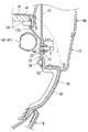
本実施例の車両用シート1は、図1を参照して、シートクッション2、シートバック4及びヘッドレスト6を備える。これら構成要素は、各々、その外形をなすパッド部材に表皮材(2S,4S,6S)を被覆して構成されている。
そして本実施例のシートバック4は、図1及び図2を参照して、バックフレーム4Fが背裏に露出するよう、パッド部材4Pを正面視略アーチ状に切り欠いて(切欠き部9を設けて)構成されている。このシートバック4のパッド部材4Pを表皮材4Sで被覆して、切欠き部9下部(シートバック4背裏下部)にバックボード8を配設したのち、切欠き部9上部(シートバック4背裏上部)にモニタパネル60を取付けることとなる。
そこで本実施例では、モニタパネル60を取付けるに際し、後述の枠部材(以下、ベゼル30とも呼ぶ)を、後述のブラケット20を介して切欠き部9上部に配設することにより、モニタパネル60を見栄え良く安定して取付ける構造としたものである。
以下、各構成要素について説明する。
The best mode for carrying out the present invention will be described below with reference to FIGS.
The vehicle seat 1 of the present embodiment includes a seat cushion 2, a
1 and 2, the
Therefore, in this embodiment, when the
Hereinafter, each component will be described.
[ブラケット]
本実施例のブラケット20は、図2を参照して、バックフレーム4F上部をなすパイプフレーム10Fに固定される金属製部材である。このブラケット20は、パイプフレーム10Fに設けた台座12の形状に合わせて上方視凹凸状とされている。そしてブラケット20両側で上下に延びる側片上下端には、後述のベゼル本体32をビス止めするための第一ビス孔21が各々設けてある。
そしてブラケット20中央には、モニタパネル60を取付けるためのスタッドボルト22が立設してある。本実施例では3本のスタッドボルト22が並列して設けてある。このスタッドボルト22の突出長さ寸法Lexは、後述するベゼル30上に配設したモニタパネル60とボルト止め可能な長さ設定とされている(図5を参照)。
[bracket]
The
A
[枠部材(ベゼル)]
そして本実施例のベゼル30は、図2を参照して、シートバック4背裏のシート外形をなすベゼル本体32と、パッド部材4Pを保持する一対の肩部40,40を備える。
ベゼル本体32は、パッド部材4Pの切欠き部9上部を補完して、シートバック4背裏のシート外形をなす部材である。本実施例のベゼル本体32は、シートバック4背側に配設されるパッド部材4P形状に合わせて縦断面凸曲面状をなしている(図5を参照)。
そして図3を参照して、このベゼル本体32を、パッド部材4Pの切欠き部9上部に配設することで、ベゼル本体32とその両側に配置のパッド部材4P(アーチ状)によりシートバック4背裏のシート形状が略面一状に構成される。
[Frame member (bezel)]
And the
The
Referring to FIG. 3, by disposing the
そしてベゼル本体32には、図2を参照して、モニタパネル60を取付けるための取付け凹部34が設けてある。
この取付け凹部34は、ベゼル本体32の略中央部分を凹状として、ベゼル本体32上方から下方にかけて深くなるよう形成されており、後述するモニタパネル60(モニタ配置の表側)よりも若干幅狭に形成されている。そして取付け凹部34内(内周壁)には、後述する表皮材4Sをクリップ止めするための複数のクリップ孔35が設けてある。
そして取付け凹部34には、ブラケット20をシートバック4背裏側に露出させるための窓部38が設けてある。また取付け凹部34内壁四隅(上述のブラケット20の第一ビス孔21配設位置との対応箇所)には、ブラケット20を固定するための第二ビス孔36が設けてある。そして後述するようにブラケット20を取付け凹部34にはめ合わせたのちビス止めすることで、ブラケット20に対するベゼル30の組付けがなされる。
The
The
The
ところで取付け凹部34の深さ寸法D(スタッドボルト22配設位置付近の深さ寸法)は、窓部38から露出したブラケット20のスタッドボルト22の突出長さ寸法Lexよりも大きくなるよう(深くなるよう)設定されている。このためベゼル本体32は、ブラケット20の組付け状態において、そのスタッドボルト22が取付け凹部34から突出しない構成である(図5を参照)。
By the way, the depth dimension D of the mounting recess 34 (depth dimension near the position where the
そして一対の肩部40,40は、図2を参照して、ベゼル本体32両側に各々設けてあり、パッド部材4Pを掛置きして下方にズレ落ちないよう保持する部材である。
本実施例の肩部40は側面視略逆L字形状をなし、ベゼル本体32よりもシート前方に突出して設けてある。そして図3を参照して、この肩部40(上片面部分)にパッド部材4Pを掛置きして(面接触状態として)保持する。そうすると、シート表側に乗員が着座してパッド部材4Pが引っ張られたとしても、パッド部材4Pが肩部40に面接触して保持されているため、シート前方向にズレにくくなる。
The pair of
The
[ベゼルの材質]
そしてベゼル30は、パッド部材4P(典型的には発泡性ウレタンなどの発泡性樹脂)よりも硬く弾縮しにくい部材であり、典型的には樹脂成形品である。
このベゼル30を構成する「樹脂」として、例えば、ポリエチレン樹脂,ポリプロピレン樹脂,ナイロン樹脂,ポレプチレンテレフタレート樹脂,ポリシクロヘキシレンジメチレンテレフタレート樹脂,ポリオキシレン樹脂,液晶ポリエステル樹脂,ポリフェニルスルフィド樹脂,ポリエーテルエーテルケトン樹脂等の「熱可塑性樹脂」や、エポキシ樹脂,フェノール樹脂,メラミン樹脂,ユリア樹脂,不飽和ポリエステル樹脂,アルキド樹脂,熱硬化性ポリイミド樹脂等の「熱硬化性樹脂」を例示できる。
なおベゼル30は、パッド部材4Pよりも硬いものであれば、マグネシウム(典型的なシートフレームの素材)などの金属製や、ゴム弾性を有する高分子(エラストマ)製であってもよい。
[Bezel material]
The
Examples of the “resin” constituting the
As long as the
[モニタパネルの取付け構造]
図2を参照して、上述のブラケット20を、シートバック4背裏にスタッドボルト22が突出する向きで、バックフレーム4F上部をなすパイプフレーム10Fに溶接して固定する(図4を参照)。
そして図3を参照して、ベゼル30の窓部38にブラケット20をはめ合わせて、ブラケット20とベゼル30を各ビス孔21,36でビス止め(ビス24)して、ブラケット20にベゼル30を位置決めして組付ける。こうすることでベゼル30を、ブラケット20を介して(パッド部材4Pを介在させることなく)、パイプフレーム10Fに直接的に固定することができる。
[Monitor panel mounting structure]
Referring to FIG. 2, the
Referring to FIG. 3, the
つぎに図3を参照して、パッド部材4Pを一対の肩部40,40に掛置きして保持したのち(略面一状のシート形状を形成したのち)、ベゼル本体32表面を表皮材4Sで被覆する。
ここでシートバック4の表皮材4S(袋状)は、図2を参照して、シートバック4背裏上部に対応する部分(取付け凹部34形成位置)に開口部50が設けてある。本実施例の開口部50は、上述の取付け凹部34よりも若干小さい開口寸法とされている。
そこで、ベゼル本体32(及びパッド部材4P)表面に表皮材4Sを被せた後、開口部50の縁部分を内折して取付け凹部34内周壁のクリップ孔35にクリップ止め(クリップ52)しておく。このように表皮材4Sを取付け凹部34内にクリップ止めすることで、後述するモニタパネル60によって表皮材4Sの固定箇所が隠されて、表皮材4Sをベゼル30に見栄えよく張設することができる。
なおベゼル30は、上述の通り、スタッドボルト22が取付け凹部34から突出しない構成であるので、スタッドボルト22が邪魔とならず(引っ掛けることなく)、表皮材4Sを被せることができる(図5を参照)。
Next, referring to FIG. 3, after the
Here, the
Therefore, after covering the surface of the bezel body 32 (and the
As described above, the
そして図2及び図5を参照して、取付け凹部34から露出するスタッドボルト22を、モニタパネル60(裏側に内設の金属板62)に設けた取付け孔64に挿入したのち、ナット26で引締めて表皮材4Sの上からモニタパネル60を取付ける。
このモニタパネル60裏側の金属板62は、ベゼル30の取付け凹部34に収納可能な幅寸法で内設されており、取付け凹部34内に収納されてスタッドボルト22でもってボルト止めされる(図6を参照)。一方、モニタパネル60表側は、ベゼル30の取付け凹部34よりも若干幅広の構成なので、モニタパネル60表側の縁が、取付け凹部34周囲のベゼル30表面に押付状態とされる。このとき表皮材4Sの厚みがほぼ半分程度となるようにモニタパネル60を押付けておくと、モニタパネル60と表皮材4Sの合わせ面を密着状として見栄えよくベゼル30に取付けることができる。
そしてモニタパネル60の取付け孔をカバー部材70で隠すことで、モニタパネル60の取付けが完了する。
2 and 5, the
The
Then, the mounting of the
このように本実施例では、図4及び図5を参照して、パッド部材4Pよりも硬い枠部材に表皮材4Sを張設して、その上からモニタパネル60を取付ける構成である。そしてモニタパネル60をベゼル30に押付けて取付けても、ベゼル30がパッド部材4Pよりも硬いため、ベゼル30を被覆する表皮材4Sの張設状態が比較的維持されてシワがよりにくい。このため本取付け構造によれば、モニタパネル60とベゼル30の合わせ面(表皮材4S)にシワがよらず、モニタパネル60をより安定して見栄えよく取付けることができる。
また本実施例では、シートバック4背裏において、ブラケット20を用いて(パッド部材4Pを介在させることなく)パイプフレーム10Fにベゼル30を直接的に固定する構成である。このためシートバック4に対するベゼル30のぐらつきが防止又は低減されて、モニタパネル60をより安定して保持することができる。
As described above, in this embodiment, referring to FIGS. 4 and 5, the
In this embodiment, the
そして本実施例では、図1を参照して、シートバック4背裏の両肩部40付近に2本の表皮材4Sの縫合線SEWが上下に走っており、本実施例のベゼル30の幅寸法Wが丁度2本の縫合線SEWの離間幅と同一寸法に設定されている。
このような構成であると、図6を参照して、ベゼル本体32とそれに当接配置するパッド部材4Pの境界線が縫合線SEWに重なり、仮に両部材間に若干の段差があったとしても表皮材4S表面を走る縫合線SEWで目立たなくなる。このため本実施例の取付け構造は、縫合線SEWのある表皮材S(複数の表皮材ピースを縫着してなる表皮材S)を典型的に使用する車両用シート1において、好適に使用することができる構造である。
In this embodiment, referring to FIG. 1, the suture lines SEW of the two
With such a configuration, referring to FIG. 6, even if the boundary line between the bezel
本実施形態の取付け構造は、上述した実施例に限定されるものではなく、その他各種の実施形態を取り得る。
(1)本実施例では、金属製のブラケット20を介してシートフレームにベゼル30を直接的に取付ける例を説明した。これとは異なり、例えば金属製のベゼルであれば、ブラケット20を介することなく直接的にバックフレーム4Fに溶接等して固定することができる。この場合には、ベゼルに直接スタッドボルトを立設する構成を採用できる。
(2)また本実施例では、ビス止めやクリップ止めなどの手段により、表皮材4Sやブラケット20をベゼル30に取付ける例を説明したが、このほかにボルト止めなどの各種取付け手段を適宜選択して用いることが可能である。すなわち本実施例のベゼル30は適度な硬さ(取付け強度)を備えるので、いずれの物理的取付け手段においても他の構成要素を確実に取付けることができる。また接着剤や融着などの各種接着手段を用いることも可能である。
The mounting structure of the present embodiment is not limited to the above-described examples, and can take various other embodiments.
(1) In this embodiment, the example in which the
(2) In this embodiment, the example in which the
1 車両用シート
4 シートバック
4F バックフレーム
4P パッド部材
4S 表皮材
8 バックボード
9 パッド部材の切欠き部
10F パイプフレーム
20 ブラケット
22 スタッドボルト
30 ベゼル
32 ベゼル本体
34 取付け凹部
38 窓部
40 肩部
50 表皮材の開口部
60 モニタパネル
DESCRIPTION OF SYMBOLS 1
Claims (5)
前記シートバック背裏には、前記パッド部材よりも硬い枠部材が前記パッド部材の代わりに配設されており、前記枠部材に前記表皮材を張設したのち、その上から前記モニタパネルを取付ける構成とし、
前記シートバック背裏に、前記パッド部材をアーチ状に切欠いてなる切欠き部を設けるとともに、起立状態の前記シートバックを基準として、前記切欠き部内の上部側に前記枠部材が配設されるモニタパネルの取付け構造。 In the mounting structure for attaching the monitor panel to the back of the vehicle seat, in which the pad member forming the outer shape of the seat is covered with a skin material, and the seat back is connected to the seat cushion so as to be able to stand upright.
A frame member that is harder than the pad member is disposed on the back of the seat back instead of the pad member, and after the skin material is stretched on the frame member, the monitor panel is mounted thereon With configuration,
A notch formed by notching the pad member in an arch shape is provided on the back of the seat back, and the frame member is disposed on the upper side in the notch with respect to the seat back in an upright state. Monitor panel mounting structure.
前記ブラケットにスタッドボルトを突設して、前記枠部材の取付け凹部内に配置するとともに、前記モニタパネルを、前記取付け凹部に配置しつつ前記スタッドボルトにてボルト止めする構成とし、
前記取付け凹部の深さ寸法を、前記スタッドボルトの突出寸法よりも大きくなるよう設定した請求項1に記載のモニタパネルの取付け構造。 When fixing the frame member directly to the seat frame of the vehicle seat without interposing the pad member, the frame member is attached to the seat frame via a bracket,
A stud bolt is protruded from the bracket and disposed in the mounting recess of the frame member, and the monitor panel is bolted with the stud bolt while being disposed in the mounting recess.
The monitor panel mounting structure according to claim 1, wherein a depth dimension of the mounting recess is set to be larger than a protruding dimension of the stud bolt.
前記本体を、前記切欠き部に配置しつつ、前記一対の肩部に、前記パッド部材を掛置きする構成とした請求項1又は2に記載のモニタパネルの取付け構造。 The frame member has a main body that forms the back of the seat back, and shoulders that protrude from both sides of the main body to the seat seating side,
The monitor panel mounting structure according to claim 1, wherein the pad member is placed on the pair of shoulder portions while the main body is disposed in the notch portion.
前記表皮材の縫合線が、前記切欠き部に配置の前記本体と、前記本体に当接する前記パッド部材との境界線上に配置する請求項1〜3のいずれかに記載のモニタパネルの取付け構造。 The frame member has a body that forms the back of the seat back,
The monitor panel mounting structure according to any one of claims 1 to 3, wherein a suture line of the skin material is disposed on a boundary line between the main body disposed in the notch and the pad member in contact with the main body. .
Priority Applications (2)
| Application Number | Priority Date | Filing Date | Title |
|---|---|---|---|
| JP2007301621A JP5248088B2 (en) | 2007-11-21 | 2007-11-21 | Monitor panel mounting structure |
| US12/271,195 US7866746B2 (en) | 2007-11-21 | 2008-11-14 | Structure of attaching monitor panel |
Applications Claiming Priority (1)
| Application Number | Priority Date | Filing Date | Title |
|---|---|---|---|
| JP2007301621A JP5248088B2 (en) | 2007-11-21 | 2007-11-21 | Monitor panel mounting structure |
Publications (2)
| Publication Number | Publication Date |
|---|---|
| JP2009125197A JP2009125197A (en) | 2009-06-11 |
| JP5248088B2 true JP5248088B2 (en) | 2013-07-31 |
Family
ID=40641127
Family Applications (1)
| Application Number | Title | Priority Date | Filing Date |
|---|---|---|---|
| JP2007301621A Active JP5248088B2 (en) | 2007-11-21 | 2007-11-21 | Monitor panel mounting structure |
Country Status (2)
| Country | Link |
|---|---|
| US (1) | US7866746B2 (en) |
| JP (1) | JP5248088B2 (en) |
Families Citing this family (19)
| Publication number | Priority date | Publication date | Assignee | Title |
|---|---|---|---|---|
| US8292364B2 (en) * | 2009-08-26 | 2012-10-23 | Edward Liu | Vehicle seat head rest with built-in electronic appliance |
| DE102009043767A1 (en) * | 2009-09-30 | 2011-03-31 | GM Global Technology Operations, Inc., Detroit | Fastening system for fastening objects to a backrest of a motor vehicle seat |
| WO2011070515A1 (en) * | 2009-12-08 | 2011-06-16 | Air New Zealand Limited | A seat |
| EP2661393A2 (en) * | 2010-12-07 | 2013-11-13 | Zodiac Seats US LLC | Passenger seat provided with screen |
| US9555726B2 (en) * | 2012-08-23 | 2017-01-31 | Zodiac Seats Us Llc | Seatback energy management system |
| KR101966614B1 (en) * | 2012-10-05 | 2019-04-08 | 현대모비스 주식회사 | Mounting apparatus for monitor in vehicle |
| US9565402B2 (en) * | 2012-10-30 | 2017-02-07 | Baby-Tech Innovations, Inc. | Video camera device and method to monitor a child in a vehicle |
| KR101374523B1 (en) * | 2012-11-28 | 2014-03-12 | 현대다이모스(주) | Monitor mounting unit for seat |
| US9469400B1 (en) * | 2014-09-08 | 2016-10-18 | Rockwell Collins, Inc. | Reconfigurable seatback for in-seat entertainment |
| TWI628095B (en) * | 2014-11-19 | 2018-07-01 | 鴻海精密工業股份有限公司 | Fixing device and car seat using the same |
| US9927642B2 (en) * | 2015-06-18 | 2018-03-27 | Ford Global Technologies, Llc | Vehicle display unit |
| US9586532B1 (en) | 2015-09-03 | 2017-03-07 | Lear Corporation | Vehicle seat assembly with entertainment system |
| EP3165405B1 (en) * | 2015-11-06 | 2018-08-29 | Dayou Holdings Co., Ltd. | Articulation type supporter for seat of a means of transportation |
| US10183631B2 (en) * | 2016-03-11 | 2019-01-22 | Ford Global Technologies, Llc | Double hook attachment system |
| US9849841B1 (en) * | 2016-06-23 | 2017-12-26 | Jet Optoelectronics Co., Ltd | Vehicle-mounted electronic apparatus |
| FR3072915B1 (en) * | 2017-10-27 | 2019-09-27 | Psa Automobiles Sa | SOLIDARIZED HOLDING DEVICE ON A VEHICLE SEAT BACK AND VEHICLE SEAT COMPRISING SUCH A BACKREST |
| US11225202B1 (en) * | 2020-09-21 | 2022-01-18 | Ford Global Technologies, Llc | Vehicle seat display assembly |
| US11679727B2 (en) | 2020-10-05 | 2023-06-20 | Toyota Boshoku Kabushiki Kaisha | Top tether bezel |
| US11351898B2 (en) * | 2020-10-15 | 2022-06-07 | Ford Global Technologies, Llc | Accessory support assembly for a vehicle seat |
Family Cites Families (22)
| Publication number | Priority date | Publication date | Assignee | Title |
|---|---|---|---|---|
| JPS63149345U (en) * | 1987-03-24 | 1988-09-30 | ||
| FR2674485B1 (en) * | 1991-03-28 | 1993-07-09 | Faure Bertrand Automobile | IMPROVEMENTS ON VEHICLE SEAT RECORDS. |
| US5267775A (en) * | 1991-10-03 | 1993-12-07 | B/E Avionics, Inc. | System for mounting a monitor |
| US5507556A (en) * | 1994-11-04 | 1996-04-16 | Burns Aerospace Corporation | Seat including an automatically adjustable display screen assembly |
| JP3029799U (en) * | 1996-04-04 | 1996-10-11 | 新和木工株式会社 | Backboard structure behind the seat back |
| JP2001047921A (en) | 1999-08-11 | 2001-02-20 | Toyota Tekkusu Osaka:Kk | Monitor mounting frame for vehicular seat and vehicular seat with monitor using the frame |
| FR2822420B1 (en) * | 2001-03-21 | 2003-07-18 | Security Vision Concept | HEADREST, PARTICULARLY FOR MOTOR VEHICLE SEAT |
| US6669285B1 (en) * | 2002-07-02 | 2003-12-30 | Eric Park | Headrest mounted video display |
| US7036879B2 (en) * | 2002-08-14 | 2006-05-02 | Johnson Safety, Inc. | Headrest-mounted monitor |
| DE10258306B4 (en) | 2002-12-13 | 2007-01-11 | Daimlerchrysler Ag | Driver's seat integrated monitor for rear passengers |
| US7188895B1 (en) * | 2003-01-24 | 2007-03-13 | Timely Innovations, Lp | Preformed foam seatback with integral opening |
| US7040697B1 (en) * | 2003-03-20 | 2006-05-09 | Timely Innovations, Lp | Headrest having an integrated video screen |
| US7597393B1 (en) * | 2003-04-04 | 2009-10-06 | Shanna Murphy, legal representative | Headrest/head restraint having an integrated video screen |
| US6739654B1 (en) * | 2003-04-24 | 2004-05-25 | Hexa-Chain Co., Ltd. | Headrest-mount display mounting structure |
| US7354091B2 (en) * | 2003-05-15 | 2008-04-08 | Audiovox Corporation | Seat mountable entertainment system |
| FR2855472B1 (en) * | 2003-05-27 | 2005-08-05 | Faurecia Sieges Automobile | VEHICLE SEAT BACKREST HAVING A TELEVISION MONITOR AND VEHICLE SEAT COMPRISING SUCH A DOSSIER |
| DE202004008205U1 (en) | 2004-05-18 | 2004-08-26 | Techcom Carcommunikation Ag | DVD player system for road vehicle passengers, has player on back seat with output fed to visual displays on back of headrests |
| US7364230B2 (en) * | 2004-10-08 | 2008-04-29 | Edward Zheng | Portable mounting device for mobile entertainment unit |
| DE102005005654B4 (en) * | 2005-02-08 | 2018-02-15 | Recaro Aircraft Seating Gmbh & Co. Kg | System comprising a screen and control unit, and a seat |
| US7591508B2 (en) * | 2005-11-02 | 2009-09-22 | Chung Lung Chang | Headrest mounted entertainment system |
| US7597394B2 (en) * | 2006-10-31 | 2009-10-06 | Edward Liu | Car seat head rest with built-in screen |
| WO2008086202A2 (en) * | 2007-01-05 | 2008-07-17 | Audiovox Corporation | Rear seat entertainment system for a vehicle having an active headrest |
-
2007
- 2007-11-21 JP JP2007301621A patent/JP5248088B2/en active Active
-
2008
- 2008-11-14 US US12/271,195 patent/US7866746B2/en active Active
Also Published As
| Publication number | Publication date |
|---|---|
| US7866746B2 (en) | 2011-01-11 |
| JP2009125197A (en) | 2009-06-11 |
| US20090127897A1 (en) | 2009-05-21 |
Similar Documents
| Publication | Publication Date | Title |
|---|---|---|
| JP5248088B2 (en) | Monitor panel mounting structure | |
| JP5485410B2 (en) | Video bezel seat attachment | |
| US20180022258A1 (en) | Vehicle structure body | |
| JP2006280454A (en) | Chair with hanger | |
| RU2659284C2 (en) | Footrest assembly for vehicle driver | |
| JP5507853B2 (en) | Chair backrest device | |
| JP2019006257A (en) | Vehicle seat | |
| JP4740626B2 (en) | Hanger mounting structure on chair | |
| JP2007118757A (en) | Vehicular seat | |
| JP5874363B2 (en) | Vehicle seat backboard mounting structure | |
| JP4731753B2 (en) | Upholstery mounting structure for chairs | |
| JP2013100001A (en) | Vehicle seat with lower cover | |
| JP4663168B2 (en) | Upholstery mounting structure for chairs | |
| JP4850361B2 (en) | Upholstery mounting structure for chairs | |
| JP2006312340A (en) | Pocket structure in interior lining | |
| JP2004135818A (en) | Method for stretching net member over seat or the like of chair | |
| JPH08280956A (en) | Seat | |
| JP2001128805A (en) | Seat plate of chair | |
| JP2009292438A (en) | Automobile interior component | |
| JP6645121B2 (en) | Chair | |
| JP2002102010A (en) | Fitting structure of cushion body of chair | |
| JP4446432B2 (en) | Chair structure and assembly method thereof | |
| JP4238082B2 (en) | Chair | |
| JP7116656B2 (en) | Load bearing member and chair with same | |
| JP4441373B2 (en) | Hanger mounting structure on chair |
Legal Events
| Date | Code | Title | Description |
|---|---|---|---|
| A621 | Written request for application examination |
Free format text: JAPANESE INTERMEDIATE CODE: A621 Effective date: 20100517 |
|
| A131 | Notification of reasons for refusal |
Free format text: JAPANESE INTERMEDIATE CODE: A131 Effective date: 20120717 |
|
| A977 | Report on retrieval |
Free format text: JAPANESE INTERMEDIATE CODE: A971007 Effective date: 20120719 |
|
| A521 | Request for written amendment filed |
Free format text: JAPANESE INTERMEDIATE CODE: A523 Effective date: 20120906 |
|
| A131 | Notification of reasons for refusal |
Free format text: JAPANESE INTERMEDIATE CODE: A131 Effective date: 20130205 |
|
| A521 | Request for written amendment filed |
Free format text: JAPANESE INTERMEDIATE CODE: A523 Effective date: 20130225 |
|
| TRDD | Decision of grant or rejection written | ||
| A01 | Written decision to grant a patent or to grant a registration (utility model) |
Free format text: JAPANESE INTERMEDIATE CODE: A01 Effective date: 20130319 |
|
| A61 | First payment of annual fees (during grant procedure) |
Free format text: JAPANESE INTERMEDIATE CODE: A61 Effective date: 20130410 |
|
| R150 | Certificate of patent or registration of utility model |
Ref document number: 5248088 Country of ref document: JP Free format text: JAPANESE INTERMEDIATE CODE: R150 Free format text: JAPANESE INTERMEDIATE CODE: R150 |
|
| FPAY | Renewal fee payment (event date is renewal date of database) |
Free format text: PAYMENT UNTIL: 20160419 Year of fee payment: 3 |
|
| R250 | Receipt of annual fees |
Free format text: JAPANESE INTERMEDIATE CODE: R250 |
|
| R250 | Receipt of annual fees |
Free format text: JAPANESE INTERMEDIATE CODE: R250 |
|
| R250 | Receipt of annual fees |
Free format text: JAPANESE INTERMEDIATE CODE: R250 |
|
| R250 | Receipt of annual fees |
Free format text: JAPANESE INTERMEDIATE CODE: R250 |
|
| R250 | Receipt of annual fees |
Free format text: JAPANESE INTERMEDIATE CODE: R250 |
|
| R250 | Receipt of annual fees |
Free format text: JAPANESE INTERMEDIATE CODE: R250 |
|
| R250 | Receipt of annual fees |
Free format text: JAPANESE INTERMEDIATE CODE: R250 |
|
| R250 | Receipt of annual fees |
Free format text: JAPANESE INTERMEDIATE CODE: R250 |
|
| R250 | Receipt of annual fees |
Free format text: JAPANESE INTERMEDIATE CODE: R250 |