JP5248085B2 - Data processing method, data processing apparatus, and program - Google Patents
Data processing method, data processing apparatus, and program Download PDFInfo
- Publication number
- JP5248085B2 JP5248085B2 JP2007280083A JP2007280083A JP5248085B2 JP 5248085 B2 JP5248085 B2 JP 5248085B2 JP 2007280083 A JP2007280083 A JP 2007280083A JP 2007280083 A JP2007280083 A JP 2007280083A JP 5248085 B2 JP5248085 B2 JP 5248085B2
- Authority
- JP
- Japan
- Prior art keywords
- data
- unit
- replacement
- decoding
- user data
- Prior art date
- Legal status (The legal status is an assumption and is not a legal conclusion. Google has not performed a legal analysis and makes no representation as to the accuracy of the status listed.)
- Expired - Fee Related
Links
Images


Classifications
-
- H—ELECTRICITY
- H04—ELECTRIC COMMUNICATION TECHNIQUE
- H04L—TRANSMISSION OF DIGITAL INFORMATION, e.g. TELEGRAPHIC COMMUNICATION
- H04L1/00—Arrangements for detecting or preventing errors in the information received
- H04L1/004—Arrangements for detecting or preventing errors in the information received by using forward error control
- H04L1/0045—Arrangements at the receiver end
- H04L1/0054—Maximum-likelihood or sequential decoding, e.g. Viterbi, Fano, ZJ algorithms
-
- H—ELECTRICITY
- H03—ELECTRONIC CIRCUITRY
- H03M—CODING; DECODING; CODE CONVERSION IN GENERAL
- H03M13/00—Coding, decoding or code conversion, for error detection or error correction; Coding theory basic assumptions; Coding bounds; Error probability evaluation methods; Channel models; Simulation or testing of codes
- H03M13/29—Coding, decoding or code conversion, for error detection or error correction; Coding theory basic assumptions; Coding bounds; Error probability evaluation methods; Channel models; Simulation or testing of codes combining two or more codes or code structures, e.g. product codes, generalised product codes, concatenated codes, inner and outer codes
- H03M13/2957—Turbo codes and decoding
-
- H—ELECTRICITY
- H03—ELECTRONIC CIRCUITRY
- H03M—CODING; DECODING; CODE CONVERSION IN GENERAL
- H03M13/00—Coding, decoding or code conversion, for error detection or error correction; Coding theory basic assumptions; Coding bounds; Error probability evaluation methods; Channel models; Simulation or testing of codes
- H03M13/37—Decoding methods or techniques, not specific to the particular type of coding provided for in groups H03M13/03 - H03M13/35
- H03M13/39—Sequence estimation, i.e. using statistical methods for the reconstruction of the original codes
- H03M13/3994—Sequence estimation, i.e. using statistical methods for the reconstruction of the original codes using state pinning or decision forcing, i.e. the decoded sequence is forced through a particular trellis state or a particular set of trellis states or a particular decoded symbol
-
- H—ELECTRICITY
- H03—ELECTRONIC CIRCUITRY
- H03M—CODING; DECODING; CODE CONVERSION IN GENERAL
- H03M13/00—Coding, decoding or code conversion, for error detection or error correction; Coding theory basic assumptions; Coding bounds; Error probability evaluation methods; Channel models; Simulation or testing of codes
- H03M13/37—Decoding methods or techniques, not specific to the particular type of coding provided for in groups H03M13/03 - H03M13/35
- H03M13/39—Sequence estimation, i.e. using statistical methods for the reconstruction of the original codes
- H03M13/41—Sequence estimation, i.e. using statistical methods for the reconstruction of the original codes using the Viterbi algorithm or Viterbi processors
-
- H—ELECTRICITY
- H04—ELECTRIC COMMUNICATION TECHNIQUE
- H04L—TRANSMISSION OF DIGITAL INFORMATION, e.g. TELEGRAPHIC COMMUNICATION
- H04L1/00—Arrangements for detecting or preventing errors in the information received
- H04L1/0078—Avoidance of errors by organising the transmitted data in a format specifically designed to deal with errors, e.g. location
Landscapes
- Engineering & Computer Science (AREA)
- Physics & Mathematics (AREA)
- Probability & Statistics with Applications (AREA)
- Theoretical Computer Science (AREA)
- Computer Networks & Wireless Communication (AREA)
- Signal Processing (AREA)
- Artificial Intelligence (AREA)
- Error Detection And Correction (AREA)
- Detection And Prevention Of Errors In Transmission (AREA)
Description
本発明は、データ処理技術、具体的には、符号化データを復号する技術に関する。 The present invention relates to a data processing technique, specifically to a technique for decoding encoded data.
デジタル通信システムにおいて、送受信されるデータの信頼性を確保するために、誤り訂正符号や誤り検出符号が用いられる。図16は、誤り訂正符号と誤り検出符号が用いられたデジタル通信システムを概略化した模式図である。 In digital communication systems, error correction codes and error detection codes are used to ensure the reliability of transmitted and received data. FIG. 16 is a schematic diagram schematically illustrating a digital communication system using an error correction code and an error detection code.
図16に示すように、送信側は、相手に送信したいデータ(送信データ)に対して、誤り検出符号化と誤り訂正符号化を施した後に変調し、変調された符号化データを得て通信路に出力する。このデータは、通信路において、誤りの原因となるノイズが混入する可能性があり。 As shown in FIG. 16, the transmission side modulates the data (transmission data) that it wants to transmit to the other party after performing error detection coding and error correction coding, and obtains the modulated coded data for communication. Output to the road. This data may be mixed with noise that causes errors in the communication path.
受信側は、受信したデータを復調して符号化データを得、この符号化データを復号する。受信側は、復号に際して誤り訂正を行い、復号により得られた復号データに対して誤り検出をする。通常、誤り検出の結果、誤り訂正が不完全な場合には、受信側は送信側にデータの再送を要求する。 The receiving side demodulates the received data to obtain encoded data, and decodes the encoded data. The receiving side performs error correction at the time of decoding, and detects errors in the decoded data obtained by decoding. Normally, when error correction is incomplete as a result of error detection, the receiving side requests retransmission of data to the transmitting side.
誤りが頻繁に検出されると、再送も多く発生し、通信システムの効率が低下する。特に移動通信システムでは、フェージングなどの影響により電波強度が激しく変動してノイズが混入しやすいため、この問題が顕著であり、受信側の高い誤り訂正能力が要求される。 If errors are frequently detected, many retransmissions occur and the efficiency of the communication system decreases. In particular, in mobile communication systems, radio wave intensity fluctuates significantly due to the influence of fading and the like, and noise is likely to be mixed in. Therefore, this problem is remarkable, and a high error correction capability on the receiving side is required.
特許文献1には、誤り訂正能力を高める手法が開示されている。図17と図18は、特許文献1における図1と図2にそれぞれ対応し、図16は、特許文献1の手法を適用した受信装置を示し、図17は該受信装置による処理の流れを示すフローチャートである。
図16に示す受信装置において、アンテナ部11は、ネットワークを介してフレームを受信し、復調部12は、受信したフレームを復調する(S11)。誤り訂正部13は、復調後のフレームに対して誤り訂正処理を行う。誤り訂正部13では、たとえばリードソロモン復号、さらにビタビ復号が行われる。
In the receiving apparatus shown in FIG. 16, the antenna unit 11 receives a frame via a network, and the
誤り検出部14は、誤り訂正処理後のフレームに含まれる誤り検出符号に基づき誤り検出処理を行う(S12、S13)。誤り検出符号は、たとえばCRC(Cyclic Redundancy Check)である。
The
誤り修正部15は、誤り検出部14において誤りが検出されたフレームに対して誤り修正処理を行う(S14:Yes、S15:Yes、S16)。この誤り修正処理は、予め取得した既知の情報を用いて、フレームの一部を置き換えるものである。例えば、誤りが検出されたフレームに含まれる送信機アドレス等を、予め取得した同一のネットワーク内の端末アドレスに置き換える。
The
その後、誤り検出部14と誤り修正部15は、フレームに誤りが無くなるまで、ステップS13〜ステップS16の処理を複数回繰り返す(S13、S14:Yes、S15、S16、S13、・・・)。また、誤りがまだあるものの、所定の終了条件を満たした場合には(S15:No)、再送制御部16は再送制御を行う(S17)。再送制御にあたり、たとえば再送制御部16は、受信したフレームに対してACK(Acknowledgement)フレームを返さないことにより、送信側にフレームの再送を行わせる。
Thereafter, the
このように、特許文献1に開示された手法は、誤りが検出されたフレームの一部のフィールドを、正常なデータである既知の情報で置き換え、置き換え後のフレームに対して再度誤り検出処理を行うことを繰り返し行うことにより誤り訂正能力を高め、その結果、誤りの検出頻度ないし再送回数が抑制される。
ところで、誤り訂正符号の代表手法として畳込符号手法が知られている。この手法は、誤り訂正の能力を向上させるために、新しい符号の作成に、拘束長Kに等しい個数の過去の符号を使用する。そのため、畳込符号化されたデータにおける符号は互いに関係し、復号時には、ノイズが混入した部分の符号は、他の符号にも影響を及ぼすことになる。 Incidentally, a convolutional code method is known as a representative method of error correction codes. This approach uses a number of past codes equal to the constraint length K to create a new code in order to improve error correction capability. For this reason, codes in convolutionally encoded data are related to each other, and at the time of decoding, a code of a part mixed with noise also affects other codes.
特許文献1の手法は、復号後のデータに対して、一部のデータを正常データで置き換えている。この一部のデータに誤りがある場合に、該データにおける誤りを修正することができるが、復号するときにこの部分のデータが用いられた他のデータにおける誤りを修正することができず、誤り訂正能力の向上効果が限られている。
In the method of
本発明の一つの態様は、データ処理方法である。このデータ処理方法は、符号化データに対して、既知データに対応する部分の少なくとも一部を正常データで置き換え、置換後の符号化データに対して復号を行う。 One aspect of the present invention is a data processing method. In this data processing method, at least a part of a portion corresponding to known data is replaced with normal data with respect to encoded data, and decoding is performed on the encoded data after replacement.
本発明の別の態様は、データ処理装置である。このデータ処理装置は、第1の記憶部と、受信部と、既知符号部分検出部と、第1の置換部と、復号部を備える。
第1の記憶部は、符号化データに含まれ得る既知符号部分の正常データを記憶する。この既知符号部分は、符号化データにおいて、既知データに対応する部分である。
受信部は、符号化データを受信し、既知符号部分検出部は、該受信部が受信した符号化データに対して、既知符号部分を検出する。
Another aspect of the present invention is a data processing apparatus. The data processing apparatus includes a first storage unit, a receiving unit, a known code part detecting unit, a first replacing unit, and a decoding unit.
The first storage unit stores normal data of a known code portion that can be included in the encoded data. This known code portion is a portion corresponding to the known data in the encoded data.
The receiving unit receives the encoded data, and the known code part detecting unit detects the known code part for the encoded data received by the receiving unit.
第1の置換部は、既知符号部分検出部が検出した既知符号部分の少なくとも一部を、第1の記憶部に記憶された正常データで置き換える。 The first replacement unit replaces at least a part of the known code part detected by the known code part detection unit with normal data stored in the first storage unit.
復号部は、既知符号部分検出部による検出の結果、既知符号部分が無いときには受信部が受信した符号化データを復号し、既知符号部分があるときには第1の置換部により置換えがなされた符号化データを復号する。 The decoding unit decodes the encoded data received by the receiving unit when there is no known code portion as a result of detection by the known code portion detecting unit, and when the known code portion is present, the first replacement unit replaces the encoded data. Decrypt the data.
本発明のさらなる別の態様は、プログラムである。このプログラムは、符号化データに対して、既知データに対応する部分を検出するステップと、該符号化データに対する復号が行われる前に、検出された既知データに対応する部分の少なくとも一部を正常データで置き換えるステップをコンピュータに実行せしめる。 Yet another embodiment of the present invention is a program. The program includes a step of detecting a portion corresponding to the known data in the encoded data, and normalizing at least a part of the portion corresponding to the detected known data before decoding the encoded data. Let the computer perform the step of replacing with data.
本発明にかかる技術によれば、誤り訂正符号化がなされたデータを復号する際に、誤り訂正能力をより高めることができる。 According to the technology of the present invention, error correction capability can be further improved when decoding data that has been subjected to error correction coding.
本発明の実施の形態を説明する前に、まず、本発明の原理について説明する。
昨今のデジタル通信システムの多くは、送信側が、送信したいデータをパケット化して符号化する。説明上の便宜のため、以下、このデータを「ユーザデータ」といい、ユーザデータをパケット化したものを「ユーザデータパケット」という。
Before describing the embodiment of the present invention, first, the principle of the present invention will be described.
In many of recent digital communication systems, a transmission side packetizes and encodes data to be transmitted. For convenience of explanation, hereinafter, this data is referred to as “user data”, and the packetized user data is referred to as “user data packet”.
パケットのサイズは、規格によって異なるが、通常、複数個の異なるパケットサイズが定められており、パケット化する際に、ユーザデータのサイズに最も近いサイズのパケットが選択される。 Although the packet size differs depending on the standard, normally, a plurality of different packet sizes are defined, and when packetizing, a packet having a size closest to the size of the user data is selected.
図1〜図3は、誤り訂正符号化前のユーザデータパケットの構成例を示す。図1に示すユーザデータパケットは、パケットサイズが「X+Y」ビットであり、Xビットのユーザデータと、YビットのCRCから構成される。このユーザデータパケットは、ユーザデータとCRCのビット数の和がパケットサイズに等しい場合の例である。 1 to 3 show a configuration example of a user data packet before error correction coding. The user data packet shown in FIG. 1 has a packet size of “X + Y” bits, and is composed of X-bit user data and a Y-bit CRC. This user data packet is an example when the sum of the number of bits of user data and CRC is equal to the packet size.
ユーザデータのビット数がXより小さく、かつユーザデータとCRCのビット数の和に最も近いパケットサイズが「X+Y」ビットである場合には、「X+Y」ビットのパケットが選択されるが、足りないビットを補うために、パディングビットやフィラービットなどの定められたデータが挿入される。パディングビットは、ユーザデータとCRCの間に挿入されるものであり、フィラービットは、ユーザデータの前に挿入されるものである。 When the number of bits of user data is smaller than X and the packet size closest to the sum of the number of bits of user data and CRC is “X + Y” bits, a packet of “X + Y” bits is selected, but not enough In order to supplement the bits, predetermined data such as padding bits and filler bits are inserted. Padding bits are inserted between user data and CRC, and filler bits are inserted before user data.
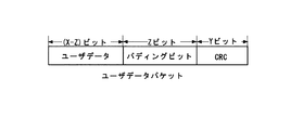
図2は、パディングビットを用いた場合のユーザデータパケットの例を示す。パケットサイズが「X+Y」ビットであり、ユーザデータのビット数が「X−Z」ビットであるため、ユーザデータとCRCの間にZビットのパディングビットが挿入されている。 FIG. 2 shows an example of a user data packet when padding bits are used. Since the packet size is “X + Y” bits and the number of bits of user data is “XZ” bits, Z padding bits are inserted between the user data and the CRC.
図3は、フィラービットを用いた場合のユーザデータパケットの例を示す。パケットサイズが「X+Y」ビットであり、ユーザデータのビット数が「X−F」であるため、ユーザデータの前にFビットのフィラービットが挿入されている。また、パディングビットとフィラービットの配列パターンは、全てが0または全てが1である場合や、0と1を織り交ぜた場合があり、 FIG. 3 shows an example of a user data packet when filler bits are used. Since the packet size is “X + Y” bits and the number of user data bits is “X−F”, F filler bits are inserted before the user data. Also, the arrangement pattern of padding bits and filler bits may be all 0s or all 1s, or may be a combination of 0s and 1s.
ビット数の不足を補うためにパディングビットが用いられるかフィラービットが用いられるか、および挿入されるビットの配列パターンは、規格によって定められている。そのため、受信側にとって、挿入されるビットは予め知られたものである。 Whether padding bits or filler bits are used to make up for the shortage of the number of bits, and the arrangement pattern of inserted bits are defined by the standard. Therefore, the inserted bit is known in advance to the receiving side.
通常、ユーザデータパケットに先行して、制御データパケットが送信される。制御データパケットは、制御データをパケット化したものであり、制御データには、次に送信されるユーザデータパケットのパケットサイズ、ユーザデータのビット数などの情報が含まれている。受信側は、制御データパケットに含まれる制御データに基づいて、ユーザデータパケットのどの部分が挿入ビットであるかを知ることができる。 Usually, the control data packet is transmitted prior to the user data packet. The control data packet is obtained by packetizing the control data, and the control data includes information such as the packet size of the user data packet to be transmitted next and the number of bits of the user data. The receiving side can know which portion of the user data packet is the insertion bit based on the control data included in the control data packet.
受信側が受信したユーザデータパケットが、図1〜図3に示すようなユーザデータパケットを誤り訂正符号化したものであるため、挿入されたビットの部分は、挿入されたビットに対応する符号になっている。この部分は、挿入されるビットの配列パターンに応じた規則性を有する。ここで具体例を用いて説明する。 Since the user data packet received by the receiving side is obtained by error-correcting the user data packet as shown in FIGS. 1 to 3, the inserted bit portion has a code corresponding to the inserted bit. ing. This part has regularity according to the arrangement pattern of the inserted bits. Here, a specific example will be described.
図4は、パディングビットがすべて「0」である図2に示すユーザデータパケットパケットを畳込符号化した場合のトレリスである。なお、畳込符号が再帰的ではなく、拘束長がKであるとする。 FIG. 4 is a trellis when the user data packet packet shown in FIG. 2 in which all the padding bits are “0” is convolutionally encoded. Note that the convolutional code is not recursive and the constraint length is K.
トレリス上において、初期状態(以下状態0という)から遷移が開始し、「K−1」時点分進んだところで全状態に遷移が至る。図4は、全状態に遷移が至った時点から示している。図示のように、全状態に遷移が至った時点から「X−Z」時点目まで、トレリス上において、全状態の遷移が続く。「X−Z+1」時点目からZ時点分のパディングビット「0」が挿入されるため、「X−Z+K−1」時点目で、トレリスは状態0に戻る。その後、パディングビットの挿入が終了するまですなわちX時点目まで、トレリス上において、状態0上の遷移を続ける。
On the trellis, a transition starts from an initial state (hereinafter referred to as a state 0), and transitions to all the states are advanced when the time is advanced by "K-1". FIG. 4 shows from the time when the transition to all states has been reached. As shown in the figure, the transition of all the states continues on the trellis from the time when the transition to all the states is reached to the “XZ” time. Since the padding bits “0” for the Z time from the “X−
「X+1」時点目以降は、パディングビットの後のYビットのCRCが順次入力されるため、トレリス上において、また状態0から遷移が開始し、「X+K」時点で全状態が遷移に至る。その後、「X+Y」時点まですなわちCRCが終了するまで全状態の遷移が続く。
Since the Y-bit CRC after the padding bits is sequentially input after the “X + 1” time point, the transition starts from the
「X+Y+1」時点に、パケットのデータの最後を示すテイルビットの「0」が入力されるため、その結果、「X+Y+K−1」時点において、トレリスは、状態0に戻る。
Since the tail bit “0” indicating the end of the packet data is input at the time “X + Y + 1”, the trellis returns to the
このように、パディングビットの入力に応じてトレリスが規則的に遷移するので、畳込符号化されたユーザデータパケットのうちの、パディングビットに対応する符号の一部を予め知ることができる。図4の例では、「X−Z+1」時点目から「X−Z+K−1」時点目までに、トレリス上の遷移が「X−Z」時点以前に入力されるデータ(ユーザデータ)に影響されるため、符号語を特定できないが、「X−Z+K」時点目からX時点目までの符号語を特定することができる。
As described above, since the trellis regularly changes according to the padding bit input, it is possible to know in advance a part of the code corresponding to the padding bit in the user data packet subjected to convolutional coding. In the example of FIG. 4, the transition on the trellis from the “X−
ここでゼロパディングを例にしているが、「1」によるパディングや、「0」と「1」を織り交ぜたパディングの場合にも、挿入されるビットに対応する部分の一部の符号語を予め知ることができる。なお、フィラービットが用いられる場合には、先頭からユーザデータの入力開始まで「0」や「1」など予め知られているビットが挿入されるので、先頭から、フィラービットの入力が終了までの部分に対応する符号語を予め知ることができる。 Here, zero padding is taken as an example, but in the case of padding by “1” or padding in which “0” and “1” are interlaced, a part of codewords corresponding to the inserted bits is also used. You can know in advance. When filler bits are used, since known bits such as “0” and “1” are inserted from the beginning to the start of user data input, from the beginning to the end of filler bit input. The codeword corresponding to the part can be known in advance.
上記の例では、畳込符号が再帰的ではないとしている。畳込符号が再帰的であるときには、パディングビットが用いられる場合にはそれに対応する符号語を知ることができないが、フィラービットが用いられる場合にはそれに対応する符号語を知ることができる。 In the above example, the convolutional code is not recursive. When the convolutional code is recursive, when the padding bits are used, the corresponding code word cannot be known, but when the filler bits are used, the corresponding code word can be known.
ここで、さらにターボ符号の場合について説明する。ターボ符号は、送信可能なデータ伝送速度の限界である「シャノン限界」に迫る符号化/復号化方式として、近年注目されている。ターボ符号では2つある畳込符号のうち、2つめの畳込符号の符号化の前に一度メモリにデータを保管する。その後、異なる順でデータを取り出すインタリーバによって,データの順番を攪拌する。復号するときには,2つの復号器を使い、該2つの復号器の結果を互いにフィードバックしながら繰り返すことによって復号を行う。 Here, the case of a turbo code will be described. In recent years, turbo codes have attracted attention as an encoding / decoding method that approaches the “Shannon limit”, which is the limit of the transmission rate of data that can be transmitted. In the turbo code, of the two convolutional codes, data is once stored in the memory before encoding the second convolutional code. Then, the order of the data is agitated by an interleaver that extracts the data in a different order. When decoding, two decoders are used, and decoding is performed by repeating the results of the two decoders while feeding back each other.
図5は、フィラービットが用いられた場合にターボ符号化により得られた要素符号を示す。図中陰影部分は、フィラービット、またはフィラービットに対応する符号を意味する。 FIG. 5 shows the element codes obtained by turbo coding when filler bits are used. The shaded part in the figure means a filler bit or a code corresponding to the filler bit.
図5に示すように、ユーザデータはパケット化によりフィラービットが挿入され、ユーザデータパケットとなる。ユーザデータパケットに対して符号化率が1/3のターボ符号化を行った結果、Systematic、1st Parity、2nd Parityの3つのパケットが得られる。Systematicと1st Parityでは、フィラービットに対応する符号は先頭に位置し、2nd Parityでは、インタリーブの作用により、フィラービットに対応する符号は、パケット内に分散されている。ここで、Systematicと1st Parityを要素符号1、インタリーブ後のSystematicと2nd Parityを要素符号2といい、それぞれの要素符号におけるトレリス上の遷移を説明する。
As shown in FIG. 5, filler bits are inserted into the user data by packetization to form user data packets. As a result of turbo coding with a coding rate of 1/3 for user data packets, three packets of Systematic, 1st Parity, and 2nd Parity are obtained. In Systematic and 1st Parity, the code corresponding to the filler bit is located at the head, and in 2nd Parity, the code corresponding to the filler bit is dispersed in the packet due to the interleaving operation. Here, Systematic and 1st Parity are referred to as an
図6は、要素符号1におけるトレリス上の遷移を示す。なお、拘束長がKであり、フィラービットのビット数がFビットであるとする。図示のように、トレリス上において、初期状態(状態0)からF時点まで状態0を遷移する。「F+1」時点以降はユーザデータが入力されるため、「F+K−1」時点で全状態が遷移に至り、その後、ユーザデータの入力が終了する時点(「F+K−1+D」時点)まで全状態の遷移が続き、終結処理により、「F+K−1+D+K−1」時点で状態0に戻る。
FIG. 6 shows a transition on the trellis in
図7は、要素符号2におけるトレリス上の遷移を示す。図中「*」が、フィラービットに対応する部分を示す。図示のように、要素符号2の場合、フィラービットに対応する部分は、トレリスの全時点に亘って分散される。 FIG. 7 shows a transition on the trellis in element code 2. In the figure, “*” indicates a portion corresponding to the filler bit. As shown in the figure, in the case of element code 2, the portion corresponding to the filler bit is distributed over all points in the trellis.
すなわち、この例の場合、要素符号2では、フィラービットに対応する部分は分散されるため、それらに対応する符号語を知ることができない。しかし、要素符号1では、トレリスは、先頭からF時点まで状態0上を遷移するため、この期間における符号語を予め知ることができる。
That is, in this example, in the element code 2, since the portions corresponding to the filler bits are dispersed, the code words corresponding to them cannot be known. However, in the
以上の説明から分かるように、誤り訂正符号化されたユーザデータパケットにおいて、パディングビットやフィラービットなど予め知られているデータに対して、それらに対応する符号語の少なくとも一部も、予め知ることができる。以下の説明において、パディングビットなどのような予め知られているデータを「既知データ」という。 As can be understood from the above description, in the user data packet subjected to error correction coding, it is possible to know in advance at least a part of codewords corresponding to previously known data such as padding bits and filler bits. Can do. In the following description, previously known data such as padding bits is referred to as “known data”.
本願発明者は、研究模索した結果、上述したことに着目して、誤り訂正符号化されたデータを復号する際の誤り訂正能力をより高める技術を確立した。図8を参照して説明する。 As a result of searching for research, the inventor of the present application has established a technique for further improving the error correction capability when decoding error-correction-encoded data, focusing on the above. This will be described with reference to FIG.
図8に示すように、ユーザデータパケットには、パディングビットなどの既知データが含まれており、誤り訂正符号化された後のユーザデータパケットには、既知データに対応する符号が含まれている。前述したように、既知データに対応する符号の少なくとも一部は、予め知られている。このような符号化されたユーザデータパケットは通信路を介して受信側に伝送される。 As shown in FIG. 8, the user data packet includes known data such as padding bits, and the user data packet after error correction coding includes a code corresponding to the known data. . As described above, at least a part of the code corresponding to the known data is known in advance. Such encoded user data packets are transmitted to the receiving side via a communication path.
本願発明者が確立した技術は、受信側において、受信したパケットを復号する前に、既知データに対応する符号部分(既知符号部分)のうちの、予め知られている部分を置換データで置き換える。この置換データは、置換えがなされる部分の正常データ、すなわちこの部分の、送信側において符号化後のデータに該当するソフトビットである。ソフトビットとは例えば、符号化後のデータが0であれば+127、1であれば−128に相当する軟値である。 The technique established by the present inventor replaces a previously known portion of the code portion corresponding to known data (known code portion) with replacement data before decoding the received packet on the receiving side. This replacement data is a soft bit corresponding to normal data of a portion to be replaced, that is, data of this portion after encoding on the transmission side. The soft bit is, for example, a soft value corresponding to +127 if the encoded data is 0 and -128 if the encoded data is 1.
こうすることによって、通信路において、置換えがなされる部分にノイズが付加されたとしても、正常データに置き換えられる。また、この置換えは、復号前に行われるので、復号時にこの部分のデータが利用される他のデータにも、ノイズの影響が波及しないことになる。 By doing so, even if noise is added to the part to be replaced in the communication path, it is replaced with normal data. Further, since this replacement is performed before decoding, the influence of noise does not spread to other data that uses this portion of data at the time of decoding.
結果として、誤り訂正能力を高め、通信システム全体の効率向上を図ることができる。 As a result, the error correction capability can be increased and the efficiency of the entire communication system can be improved.
以上の説明を踏まえ、本発明の技術にかかる実施の形態について説明する。
<第1の実施の形態>
図9は、本発明の第1の実施の形態にかかる受信装置100を示す。この受信装置100は、ネットワーク例えば無線通信網を介してデータを受信し、受信データを復号するものである。例として、本実施の形態において、受信データは、送信側においてユーザデータに対して誤り検出符号化と誤り訂正符号化し、さらに変調したものであり、誤り訂正符号としては畳込符号が用いられている。また、受信装置100は、復号に際してビタビ復号の手法を用いる。
Based on the above description, an embodiment according to the technique of the present invention will be described.
<First Embodiment>
FIG. 9 shows the receiving
図9に示すように、受信装置100は、アンテナ110と、復調部112と、制御データ復号部114と、CPU(Central Processing Unit)116と、ユーザデータ復号部120を備える。
As illustrated in FIG. 9, the
アンテナ110は、無線通信網を介してデータを受信し、受信データを復調部112に出力する。
復調部112は、受信データを復調し、復調されたデータが制御データパケットである場合には制御データ復号部114に出力し、復調されたデータがユーザデータパケットである場合にはユーザデータ復号部120に出力する。
The
The
復調部112からの制御データパケットが符号化されたものであり、制御データ復号部114は、それを復号してCPU116に出力する。
CPU116は、制御データ復号部114からの制御データに基づいて、ユーザデータパケットの復号に必要な参照情報を生成してユーザデータ復号部120に出力する。この参照情報は、ユーザデータパケットのパケットサイズ、ユーザデータのビット数などの情報が含まれている。
The control data packet from the
The
ユーザデータ復号部120は、コントローラ130と、入力メモリ140と、ビタビデコーダ150と、出力メモリ170と、誤り検出部180を備える。
The user
コントローラ130は、たとえばDSP(Digital Signal Processor)であり、ユーザデータ復号部120の他の構成要素を制御する。入力メモリ140は、復調部112からのユーザデータパケットを格納し、ビタビデコーダ150に供給する。ビタビデコーダ150は、入力メモリ140からユーザデータパケットを読み出して復号し、復号されたユーザデータすなわち復号データを出力メモリ170に出力する。出力メモリ170は、ビタビデコーダ150からの復号データを格納する。出力メモリ170に格納された復号データは、誤り検出部180により誤り検出がなされ、のちに出力される。
The
誤り検出部180は、出力メモリ170に格納された復号データに対して誤り検出を行い、検出の結果をコントローラ130に出力する。
The
図10を参照して、ユーザデータ復号部120を詳細に説明する。
図10に示すように、ユーザデータ復号部120におけるビタビデコーダ150は、第1の置換部152と、監視部154と、ACS演算部156と、バッファ158と、内部メモリ160と、トレースバック部162と、第2の置換部164と、監視部166を有する。
The user
As shown in FIG. 10, the
入力メモリ140は、復調部112からの、符号化されたユーザデータパケットを格納すると共に、置換データ142も格納している。この置換データ142は、受信装置100が準拠した規格により定められた、ユーザデータパケットにおけるパディングビットなどの既知データに対応する符号である。
The
出力メモリ170にも、置換データ172が格納されている。この置換データ172は、入力メモリ140に格納された置換データ142と異なり、既知データそのものである。
The
コントローラ130は、ビタビデコーダ150と誤り検出部180に起動制御信号を出力し起動させる制御を行う。また、コントローラ130は、CPU116からの参照情報に基づいて置換パラメータを取得し、ビタビデコーダ150のバッファ158に出力する。コントローラ130からの置換パラメータは、第1の置換部152用のものと、第2の置換部164が用いるものである。
The
第1の置換部152用の置換パラメータは、入力メモリ140に格納された、復調部112からの符号化されたユーザデータパケットに対して置換えがなされる部分の開始アドレスとサイズである。コントローラ130は、CPU116からの参照情報に基づいて、既知データに対応する符号の位置とビット数を算出すると共に、既知データに対応する符号のうちの、置換えがなされる部分の開始アドレスとサイズを取得してバッファ158に出力する。すなわち、コントローラ130は、請求項でいう既知符号部分検出部を兼ねる。以下、置換えがなされる部分を置換対象という。
The replacement parameters for the
第2の置換部164用の置換パラメータは、後に出力メモリ170に格納される復号データ(復号されたユーザデータパケット)に対して置換がなされる部分の開始アドレスとサイズである。コントローラ130は、CPU116からの参照情報に基づいて、復号後のユーザデータパケットにおける既知データの位置とビット数を算出して、バッファ158に出力する。
The replacement parameter for the
ビタビデコーダ150において、ACS演算部156は、ACS(Add Compare Select:加算、比較、選択)処理を繰り返し、演算結果を内部メモリ160に格納する。トレースバック部162は、ビタビ復号の最後のステップであるトレースバック処理を行って復号データを得る。
In the
監視部154は、ACS演算部156がACS演算中に入力メモリ140からデータを読み出す際のアドレスを監視し、このアドレスが、第1の置換部152用の置換パラメータが示す置換対象のアドレスではなければ、第1の置換部152を介して、当該データを読み出してACS演算部156に供する。一方、上記アドレスが置換対象のアドレスであれば、監視部154は、第1の置換部152に置換えを指示する。
The
第1の置換部152は、監視部154から置換えが指示されると、当該アドレスのデータを、入力メモリ140に格納された置換データ142で置き換えてACS演算部156に出力する。
When the replacement is instructed from the
監視部166は、トレースバック部162が復号データを出力メモリ170に書き込む際のアドレスを監視し、このアドレスが、第2の置換部164用の置換パラメータが示す置換対象のアドレスではなければ、第2の置換部164を介して、トレースバック部162が出力する復号データをそのまま出力メモリ170に書き込む。一方、上記アドレスが置換対象のアドレスであれば、監視部166は、第2の置換部164に置換えを指示する。
The
第2の置換部164は、監視部166から置換えが指示されると、トレースバック部162からの復号データを、出力メモリ170に格納された置換データ172で置き換えて出力メモリ170に出力する。
When the replacement is instructed from the
誤り検出部180は、出力メモリ170に格納された復号データ(第2の置換部164により置換えがなされたデータを含む)に対して誤り検出を行い、検出結果をコントローラ130に出力する。
The
コントローラ130は、誤り検出部180からの検出結果に基づいて誤り制御を行う。誤り制御は、たとえば、誤りが検出された場合にACKを送信側に送り返さないように当該パケットを再送させるなどの処理が含まれる。
The
このように、本第1の実施の形態にかかる受信装置100は、ユーザデータパケットを復号する前に既知データに対応する符号を正常データで置き換えている。こうすることにより、通信路において、置換対象部分にノイズが混入したとしても、正常データに置き換えられる。また、この置換えは、復号前に行われるので、復号時にこの部分が利用される他のデータにも、ノイズの影響が波及しないことになる。結果として、高い誤り訂正能力を得ることができる。
As described above, the receiving
さらに、既知データに対応する符号の復号時に、他の部分の符号が利用される。そのため、他の部分にノイズが混入した場合には、復号データにおける既知データの部分も正常なデータではない恐れがある。受信装置100は、復号後のデータに対しても既知データの部分を正常データに置き換えているので、復号データにおける誤りをさらに軽減し、誤り訂正能力をより高めることができる。
Furthermore, the code of the other part is used when decoding the code corresponding to the known data. Therefore, when noise is mixed in other portions, there is a possibility that the known data portion in the decoded data is not normal data. Since the receiving
また、受信装置100では、ビタビデコーダ150に設けられたハードウェア構成の2つの置換部により置換えがなされるので、処理の高速化を図ることができる。
<第2の実施の形態>
Further, in the receiving
<Second Embodiment>
図11は、本発明の第2の実施の形態として、図1に示す受信装置100において、ユーザデータ復号部120の代わりに適用可能なユーザデータ復号部220を示す。図11において、図10に示すユーザデータ復号部120と同様な構成要素については同じ符号を付与し、それらの説明を省略する。
FIG. 11 shows a user
図11に示すユーザデータ復号部220において、コントローラ230は、図10に示すユーザデータ復号部120のコントローラ130の機能以外に、第1の置換部152と、監視部154と、第2の置換部164と、監視部166の機能を備える。そのため、ビタビデコーダ250には、これらの機能を担う構成要素が無く、ACS演算部156と、内部メモリ160と、トレースバック部162から構成される。
In the user
コントローラ230は、参照情報に基づいて、入力メモリ140に格納されたユーザデータパケットにおける置換対象部分のアドレスとサイズを算出し、当該部分を置換データ142で上書きすることによって置き換える。置換後、コントローラ230は、ビタビデコーダ250に起動制御信号を出力して起動させる。
Based on the reference information, the
また、トレースバック部162から出力メモリ170に復号データが書き込まれた際に、コントローラ230は、復号データにおける置換対象部分のデータを置換データ172で上書きする。そして、上書きの後に、コントローラ230は、誤り検出部180に起動制御信号を出力し起動させる。
Further, when the decoded data is written from the
すなわち、本実施の形態において、図10に示すビタビデコーダ150における第1の置換部152と、監視部154と、第2の置換部164と、監視部166の処理は、コントローラ230に実装されたプログラムにより行われる。そのため、図10に示すユーザデータ復号部120と同様に高い誤り訂正能力を得ることができると共に、第1の置換部152と、監視部154と、第2の置換部164と、監視部166の回路の分、回路規模を削減することができる。
That is, in the present embodiment, the processing of the
さらに、入力メモリ140に格納されたユーザデータパケットに対する置換えの後にビタビデコーダ250を起動し、出力メモリ170に格納された復号データに対する置換えの後に誤り検出部180を起動するようにしているので、ビタビデコーダ250と誤り検出部180の稼動時間を短縮することができ、電力消費を抑制することができる。
Further, since the
図12は、本発明の技術を適用した上記2つのユーザデータ復号部の誤り訂正能力と、従来技術の誤り訂正能力を比較する図である。横軸は、信号とノイズのパワー比であり、数値が小さいほどノイズが多いことを意味する。縦軸は、ブロックエラー率であり、数値が小さいほど誤りが少ないことを意味する。また、図中「×」は、既知データや、既知データに対応する符号の置換えが行われない場合の結果であり、「△」は、特許文献1の手法による結果であり、「○」は、上記2つのユーザデータ復号部による結果である。
FIG. 12 is a diagram comparing the error correction capability of the two user data decoding units to which the technology of the present invention is applied and the error correction capability of the conventional technology. The horizontal axis is the signal to noise power ratio, and the smaller the value, the more noise. The vertical axis represents the block error rate, and the smaller the numerical value, the smaller the error. Further, “x” in the figure is the result when the replacement of the known data and the code corresponding to the known data is not performed, “Δ” is the result by the method of
例えば、Eb/Noが1.8dBのときに、本発明の技術によればブロックエラー率が約0.01であり、特許文献1の手法によればブロックエラー率が約0.025であり、置換えがなされない場合のブロックエラー率が約0.1である。すなわち、同様の1.8dBのノイズ量に対して、置換えがなされない場合には10ブロック(ユーザデータパケット)に1つの誤りがあり、特許文献1の手法によれば40ブロックに1つの誤りがあるのに対して、本発明の手法によれば、100ブロックに1つの誤りしかない。
<第3の実施の形態>
For example, when Eb / No is 1.8 dB, the block error rate is about 0.01 according to the technique of the present invention, and the block error rate is about 0.025 according to the technique of
<Third Embodiment>
図13は、本発明の第3の実施の形態にかかるユーザデータ復号装置320を示す。このユーザデータ復号装置320は、図9に示す受信装置100がターボ符号化されたデータを受信するものである場合に、受信装置100におけるユーザデータ復号部120の代わりに適用されるものである。図13において、図10に示すユーザデータ復号部120と同様な構成要素については同じ符号を付与し、それらの説明を省略する。また、例として、符号化されたデータの態様は、図5に示す「Systematic」、「1st Parity」、「2nd Parity」の3種類である。
FIG. 13 shows a user
ユーザデータ復号装置320は、コントローラ330と、入力メモリ140と、ターボデコーダ350と、硬判定/誤り検出部382と、出力メモリ384を備える。
The user
入力メモリ140は、符号化されたユーザデータパケットを格納すると共に、置換データ142も格納している。この置換データ142は、ユーザデータ復号装置320が準拠した規格により定められた、ユーザデータパケットにおけるフィラービットなどの既知データに対応する符号である。
The
ターボデコーダ350は、第1の置換部352と、監視部354と、バッファ358と、MAP復号部360と、監視部366と、第2の置換部368と、中間メモリ370を有する。
The
MAP復号部360は、第1の復号器362と第2の復号器364を有する。中間メモリ370は、インタリーバ374とデインタリーバ376を有し、さらに置換データ372を格納している。
The
MAP復号部360において、2つの復号器が、中間メモリ370を介して、復号結果を外部情報として互いにフィードバックしながら復号を進める。この外部情報は、ユーザデータパケットの復号データを得るまでの中間データである。
In the
第1の復号器362は、入力メモリ140から「Systematic」と「1st Parity」を、デインタリーバ376から第2の復号器364が出力した外部情報を読み出して、これらを用いて軟出力復号を行う。なお、1回目の軟出力復号時において、まだデインタリーバ376に外部情報が書き込まれていないので、外部情報が取りうる値の中間値例えばセロが用いられる。第1の復号器362は、軟出力復号により得られた外部情報をインタリーバ374に書き込む。
The
次いで、第2の復号器364は、入力メモリ140から「Systematic」と「2nd Parity」を、インタリーバ374から第1の復号器362が出力した外部情報を読み出して、これらを用いて軟出力復号を行う。第2の復号器364は、軟出力復号により得られた外部情報をデインタリーバ376に書き込む。
Next, the
第1の復号器362と第2の復号器364による上記処理は、規格により定められた所定回数繰り返される。最後の回において、第2の復号器364は、第1の復号器362が用いる外部情報ではなく、軟出力の対数尤度比をデインタリーバ376に書込む。なお、対数尤度比には、フィラービットは除去されている。
The above processing by the
硬判定/誤り検出部382は、デインタリーバ376から対数尤度比を読み出して硬判定を行って、硬判定の結果を復号データとして出力メモリ384に出力すると共に、CRCに基づく誤り検出をし、検出結果をコントローラ330に出力する。
The hard decision /
コントローラ330は、ターボデコーダ350と硬判定/誤り検出部382に起動制御信号を出力し起動させる制御を行う。また、コントローラ330は、硬判定/誤り検出部382からの検出結果に基づいた誤り制御も行う。誤り制御は、たとえば、誤りが検出された場合にACKを送信側に送り返さないように当該パケットを再送させるなどの処理が含まれる。
The
さらに、コントローラ330は、参照情報に基づいて置換パラメータを取得し、ターボデコーダ350のバッファ358に出力する。コントローラ330からの置換パラメータは、第1の置換部352用のものと、第2の置換部368が用いるものである。
Further, the
第1の置換部352用の置換パラメータは、入力メモリ140に格納された、符号化されたユーザデータパケットに対して置換えがなされる部分の開始アドレスとサイズである。コントローラ330は、参照情報に基づいて、既知データに対応する符号の位置とビット数を算出すると共に、既知データに対応する符号のうちの、置換えがなされる部分の開始アドレスとサイズを取得してバッファ358に出力する。
The replacement parameter for the
第2の置換部368用の置換パラメータは、中間メモリ370のインタリーバ374とデインタリーバ376に格納される外部情報における置換対象部分の開始アドレスとサイズである。コントローラ330は、参照情報に基づいて、外部情報における置換対象部分の位置とビット数を算出して、バッファ358に出力する。
The replacement parameter for the
中間メモリ370には、置換データ372が格納されている。この置換データ372は、入力メモリ140に格納された置換データ142と異なり、外部情報における置換対象部分の正常データである。
In the
監視部354は、MAP復号部360が入力メモリ140からデータを読み出す際のアドレスを監視し、このアドレスが、第1の置換部352用の置換パラメータが示す置換対象のアドレスではなければ、第1の置換部352を介して、当該データを読み出してMAP復号部360に供する。一方、上記アドレスが置換対象のアドレスであれば、監視部354は、第1の置換部352に置換えを指示する。
The
第1の置換部352は、監視部354から置換えが指示されると、当該アドレスのデータを、入力メモリ140に格納された置換データ142で置き換えてMAP復号部360に出力する。
When the replacement is instructed from the
監視部366は、MAP復号部360が外部情報を中間メモリ370に書き込む際のアドレスを監視し、このアドレスが、第2の置換部368用の置換パラメータが示す置換対象のアドレスではなければ、第2の置換部368を介して、当該外部情報を中間メモリ370に出力する。一方、上記アドレスが置換対象のアドレスであれば、監視部366は、第2の置換部368に置換えを指示する。
The
第2の置換部368は、監視部366から置換えが指示されると、MAP復号部360からの外部情報を置換データ372で置き換えて中間メモリ370に書き込む。
When the replacement is instructed from the
監視部366と第2の置換部368は、MAP復号部360が中間メモリ370から外部情報を読み出す際にも同様の処理を行い、外部情報における置換対象の部分を置換データ372で置き換えてMAP復号部360に供する。
The
このように、本第3の実施の形態にかかるユーザデータ復号装置320は、ターボ符号化されたユーザデータパケットを復号する前に既知データに対応する符号を正常データで置き換えている。こうすることにより、通信路において、置換対象部分にノイズが混入したとしても、正常データに置き換えられる。また、この置換えは、復号前に行われるので、復号時にこの部分が利用される他のデータにも、ノイズの影響が波及しないことになる。
As described above, the user
さらに、ユーザデータ復号装置320は、復号中のデータ(外部情報)に対しても既知データに対応する部分を正常データに置き換えているので、誤りをさらに軽減し、誤り訂正能力をより高めることができる。
Furthermore, since the user
また、ユーザデータ復号装置320では、ターボデコーダ350に設けられたハードウェア構成の2つの置換部により置換えがなされるので、処理の高速化を図ることができる。
<第4の実施の形態>
Further, in the user
<Fourth embodiment>
図14は、本発明の第4の実施の形態にかかるユーザデータ復号装置420を示す。図14において、図13に示すユーザデータ復号装置320と同様な構成要素については同じ符号を付与し、それらの説明を省略する。
FIG. 14 shows a user
図14に示すユーザデータ復号装置420において、コントローラ430は、図13に示すユーザデータ復号装置320のコントローラ330の機能以外に、第1の置換部352と、監視部354と、監視部366と、第2の置換部368の機能を備える。そのため、ターボデコーダ450には、これらの機能を担う構成要素が無く、MAP復号部360と、中間メモリ370から構成される。
In the user
コントローラ430は、参照情報に基づいて、入力メモリ140に格納されたユーザデータパケットにおける置換対象部分のアドレスとサイズを算出し、当該部分を置換データ142で上書きすることによって置き換える。置換後、コントローラ430は、ターボデコーダ450に起動制御信号を出力して起動させる。
Based on the reference information, the
また、MAP復号部360から中間メモリ370に外部情報が書き込まれた際に、コントローラ430は、外部情報における置換対象部分のデータを置換データ372で上書きする。そして、上書きの後に、コントローラ430は、硬判定/誤り検出部382に起動制御信号を出力し起動させる。
Further, when external information is written from the
すなわち、本実施の形態において、図13に示すターボデコーダ350における第1の置換部352と、監視部354と、第2の置換部368と、監視部366の処理は、コントローラ430に実装されたソフトウェアにより行われる。そのため、図13に示すユーザデータ復号装置320と同様に高い誤り訂正能力を得ることができると共に、第1の置換部352と、監視部354と、第2の置換部368と、監視部366の回路の分、回路規模を削減することができる。
That is, in the present embodiment, the processing of the
さらに、入力メモリ140に格納されたユーザデータパケットに対する置換えの後にターボデコーダ450を起動し、中間メモリ370に格納された外部情報に対する置換えの後に硬判定/誤り検出部382を起動するようにしているので、ターボデコーダ450と硬判定/誤り検出部382の稼動時間を短縮することができ、電力消費を抑制することができる。
Further, the
図15は、図13に示すユーザデータ復号装置320と図14に示すユーザデータ復号装置420の誤り訂正能力と、既知データの置換えがなされない従来技術の誤り訂正能力を比較する図である。横軸は、信号とノイズのパワー比であり、縦軸は、図12のブロックエラーと同義のフレームエラー率である。また、実線は、本発明の技術を適用した結果を示し、点線は、従来技術の結果を示す。図中「1024fr0」や「1024fr1」の表記では、「fr」の前の数値は、フレーム(ユーザデータパケット)のサイズを示し、「fr」の後の数値「0」は従来技術の場合を示し、「fr」の後の数値「1」は本発明の技術の場合を示す。なお、フレームのサイズによってフィラービットのサイズも異なり、たとえば1024ビットのフレームにおいて31ビットのフィラービットがあり、2048ビットのフレームにおいてが63ビットのフィラービットがある。
FIG. 15 is a diagram comparing the error correction capability of user
図15から、いずれのフレームサイズでも、本発明の技術によれば、同一のノイズ量に対して、フレームエラー率は従来技術のときより低いことが分かる。 From FIG. 15, it can be seen that the frame error rate is lower than that of the prior art for the same amount of noise, regardless of the frame size.
さらに、同一のフレームエラー率を得るためのコーディングゲイン(符号化利得)を比較してみる。たとえば、フレームエラー率が0.1(10フレームに1フレームが誤る)の場合において、1024ビットと2048のいずれのフレームサイズでも、本発明の技術のほうが、従来技術より約0.06dB程度のコーディングゲインの向上を実現している。これは、同じ量のデータを送信するために必要な送信電力を削減できることを意味する。 Furthermore, the coding gain (encoding gain) for obtaining the same frame error rate will be compared. For example, when the frame error rate is 0.1 (1 frame is erroneous in 10 frames), the technique of the present invention is about 0.06 dB coding than the conventional technique regardless of the frame size of 1024 bits and 2048. Gain improvement is realized. This means that the transmission power required to transmit the same amount of data can be reduced.
以上、実施の形態をもとに本発明を説明した。実施の形態は例示であり、本発明の主旨から逸脱しない限り、さまざまな変更、増減を加えてもよい。これらの変更、増減が加えられた変形例も本発明の範囲にあることは当業者に理解されるところである。 The present invention has been described above based on the embodiment. The embodiment is an exemplification, and various changes and increases / decreases may be added without departing from the gist of the present invention. It will be understood by those skilled in the art that modifications to which these changes and increases / decreases are also within the scope of the present invention.
例えば、上述した各実施の形態において、既知データのすべてが「0」であるため、復号前の置換データはこのような既知データに対応する符号の1種類であり、復号後の置換データは既知データと同様の「0」である。送信側が用いる既知データは、すべてが「0」、すべてが「1」、および「0」と「1」を織り交ぜたものいずれである可能性もある場合には、各場合に対応した複数の種類の復号前/復号後の置換データを用意しておき、制御データにより通知される既知データの種類に応じて複数の種類の置換データを選択的に用いるようにしてもよい。 For example, in each of the embodiments described above, since all of the known data is “0”, the replacement data before decoding is one type of code corresponding to such known data, and the replacement data after decoding is known. It is “0” like the data. The known data used by the transmitting side is all “0”, all “1”, and a combination of “0” and “1”. It is also possible to prepare replacement data of before / after decoding of types and selectively use a plurality of types of replacement data according to the types of known data notified by the control data.
また、既知データの配列パターンが複雑である場合には、送信側の符号器と同様の符号器を受信側に設け、制御データにより通知された配列パターンの既知データをこの符号器に入力して符号化することにより、復号前の置換データを生成するようにしてもよい。 If the arrangement pattern of the known data is complicated, an encoder similar to the encoder on the transmission side is provided on the reception side, and the known data of the arrangement pattern notified by the control data is input to this encoder. It is also possible to generate replacement data before decoding by encoding.
100 受信装置 110 アンテナ
112 復調部 114 制御データ復号部
120 ユーザデータ復号部 130 コントローラ
140 入力メモリ 142 置換データ
150 ビタビデコーダ 152 第1の置換部
154 監視部 156 演算部
158 バッファ 160 内部メモリ
162 トレースバック部 164 第2の置換部
166 監視部 170 出力メモリ
172 置換データ 180 誤り検出部
220 ユーザデータ復号部 230 コントローラ
250 ビタビデコーダ 320 ユーザデータ復号装置
330 コントローラ 350 ターボデコーダ
352 第1の置換部 354 監視部
358 バッファ 360 MAP復号部
362 第1の復号器 364 第2の復号器
366 監視部 368 第2の置換部
370 中間メモリ 372 置換データ
374 インタリーバ 376 デインタリーバ
382 硬判定/誤り検出部 384 出力メモリ
420 ユーザデータ復号装置 430 コントローラ
450 ターボデコーダ
DESCRIPTION OF
Claims (1)
送信された前記符号化データを受信する受信部と、 A receiving unit for receiving the transmitted encoded data;
該受信部が受信した前記符号化データに対して、前記既知符号部分を検出する既知符号部分検出部と、 A known code part detection unit for detecting the known code part for the encoded data received by the receiving unit;
該既知符号部分検出部が検出した前記既知符号部分の少なくとも一部を、受信側で、前記第1の記憶部に記憶された前記正常データで置き換える第1の置換部と、A first replacement unit that replaces at least a part of the known code part detected by the known code part detection unit with the normal data stored in the first storage unit on the receiving side;
前記既知符号部分検出部による検出の結果、前記既知符号部分が無いときには前記受信部が受信した符号化データを最尤復号し、前記既知符号部分があるときには前記第1の置換部により置換えがなされた前記符号化データを最尤復号する復号部とを備えるデータ処理装置であって、 As a result of detection by the known code part detection unit, when there is no known code part, the encoded data received by the receiving unit is subjected to maximum likelihood decoding, and when the known code part is present, replacement is performed by the first replacement unit. A data processing device comprising a decoding unit for maximum likelihood decoding the encoded data,
前記符号化データは、ターボ符号化されたものであり、 The encoded data is turbo encoded,
前記復号部は、2つの復号器と中間メモリを有し、該2つの復号器を前後に実行させることを繰り返すものであり、 The decoding unit includes two decoders and an intermediate memory, and repeatedly executes the two decoders before and after,
前記中間メモリは、前記2つの復号器のそれぞれの実行結果である中間データを格納するものであり、 The intermediate memory stores intermediate data that is an execution result of each of the two decoders.
前記2つの復号器は、片方の実行時に、他方が直前に得られた前記中間データを前記中間メモリから読み出して使用するものであり、 The two decoders, when one of them is executed, the other reads out the intermediate data obtained immediately before from the intermediate memory and uses it.
前記中間データに含まれうる、前記既知データに対応する部分の正常データを記憶する第2の記憶部と、 A second storage unit that stores normal data of a portion corresponding to the known data, which can be included in the intermediate data;
前記既知符号部分検出部により前記既知符号部分が検出されたときに、当該符号化データの前記中間データに対して、該中間データが前記中間メモリから読み出される前に、前記既知データに対応する部分の少なくとも一部を、前記第2の記憶部に記憶された正常データで置き換える第2の置換部とをさらに備えることを特徴とするデータ処理装置。 A portion corresponding to the known data before the intermediate data is read from the intermediate memory with respect to the intermediate data of the encoded data when the known code portion is detected by the known code portion detection unit. A data processing device further comprising: a second replacement unit that replaces at least a part of the data with normal data stored in the second storage unit.
Priority Applications (2)
| Application Number | Priority Date | Filing Date | Title |
|---|---|---|---|
| JP2007280083A JP5248085B2 (en) | 2007-10-29 | 2007-10-29 | Data processing method, data processing apparatus, and program |
| US12/285,751 US8201052B2 (en) | 2007-10-29 | 2008-10-14 | Data processing method of decoding coded data and data processor for the same |
Applications Claiming Priority (1)
| Application Number | Priority Date | Filing Date | Title |
|---|---|---|---|
| JP2007280083A JP5248085B2 (en) | 2007-10-29 | 2007-10-29 | Data processing method, data processing apparatus, and program |
Publications (2)
| Publication Number | Publication Date |
|---|---|
| JP2009111563A JP2009111563A (en) | 2009-05-21 |
| JP5248085B2 true JP5248085B2 (en) | 2013-07-31 |
Family
ID=40584472
Family Applications (1)
| Application Number | Title | Priority Date | Filing Date |
|---|---|---|---|
| JP2007280083A Expired - Fee Related JP5248085B2 (en) | 2007-10-29 | 2007-10-29 | Data processing method, data processing apparatus, and program |
Country Status (2)
| Country | Link |
|---|---|
| US (1) | US8201052B2 (en) |
| JP (1) | JP5248085B2 (en) |
Families Citing this family (4)
| Publication number | Priority date | Publication date | Assignee | Title |
|---|---|---|---|---|
| US7587005B2 (en) * | 2006-03-28 | 2009-09-08 | Research In Motion Limited | Exploiting known padding data to improve block decode success rate |
| FR2970131B1 (en) * | 2011-01-03 | 2013-01-04 | Centre Nat Etd Spatiales | METHOD OF CORRECTING MESSAGES CONTAINING JAM BITS |
| FR2970130B1 (en) * | 2011-01-03 | 2013-08-30 | Centre Nat Etd Spatiales | DECODING METHOD AND DECODER |
| WO2012131856A1 (en) | 2011-03-25 | 2012-10-04 | 富士通株式会社 | Information processing device, tampering detection device, information processing method, tampering detection method, information processing program, and tampering detection program |
Family Cites Families (11)
| Publication number | Priority date | Publication date | Assignee | Title |
|---|---|---|---|---|
| US5504759A (en) * | 1991-07-11 | 1996-04-02 | Sony Corporation | Digital signal recording and/or reproducing apparatus using a common processing device for digital signals having different data configurations |
| JPH0555932A (en) * | 1991-08-23 | 1993-03-05 | Matsushita Electric Ind Co Ltd | Error correction coding and decoding device |
| JPH10262034A (en) * | 1997-03-19 | 1998-09-29 | Sharp Corp | Coding and decoding device |
| JP3167663B2 (en) * | 1997-10-23 | 2001-05-21 | 三洋電機株式会社 | Encoding / decoding method of error correction code |
| DE69942684D1 (en) * | 1998-04-18 | 2010-09-30 | Samsung Electronics Co Ltd | Turbo coding with insertion of known bits |
| JP2001024717A (en) * | 1999-07-07 | 2001-01-26 | Matsushita Electric Ind Co Ltd | Turbo decoding device and reiterative decoding method |
| JP4784030B2 (en) * | 2001-09-21 | 2011-09-28 | ソニー株式会社 | Recording apparatus, reproducing apparatus, recording method, reproducing method |
| JP4183471B2 (en) * | 2002-10-08 | 2008-11-19 | 富士通株式会社 | Receiver for receiving transmission information with padding added |
| KR100683879B1 (en) * | 2004-05-06 | 2007-02-15 | 삼성전자주식회사 | Digital broadcasting transmission/reception capable of improving receiving performance and signal processing method thereof |
| JP4768324B2 (en) * | 2005-06-07 | 2011-09-07 | 株式会社東芝 | Wireless communication equipment |
| US7983354B2 (en) * | 2005-11-25 | 2011-07-19 | Samsung Electronics Co., Ltd. | Digital broadcast transmitter/receiver having an improved receiving performance and signal processing method thereof |
-
2007
- 2007-10-29 JP JP2007280083A patent/JP5248085B2/en not_active Expired - Fee Related
-
2008
- 2008-10-14 US US12/285,751 patent/US8201052B2/en not_active Expired - Fee Related
Also Published As
| Publication number | Publication date |
|---|---|
| US8201052B2 (en) | 2012-06-12 |
| JP2009111563A (en) | 2009-05-21 |
| US20090113270A1 (en) | 2009-04-30 |
Similar Documents
| Publication | Publication Date | Title |
|---|---|---|
| JP3910770B2 (en) | Error control method and receiver using the method | |
| US8984364B2 (en) | Multiple interleavers in a coding system | |
| JP2005245027A (en) | Turbo-coding with staged data transmission and processing | |
| US20060085726A1 (en) | Apparatus and method for decoding Reed-Solomon code | |
| US6606724B1 (en) | Method and apparatus for decoding of a serially concatenated block and convolutional code | |
| JP3613448B2 (en) | Data transmission method, data transmission system, transmission device, and reception device | |
| JPH08228190A (en) | Progressive error correction system and its method | |
| JP2002501707A (en) | Method and apparatus for error protection of wireless file transfer | |
| KR19980064845A (en) | Coding and decoding system using seed check bits | |
| WO1997014225A9 (en) | A coding system and method providing unequal error protection by puncturing less significant symbols | |
| JP3440092B1 (en) | Error correction decoding device and error correction decoding method | |
| JP2002043953A (en) | Error correction method and error correction device | |
| JP2006303906A (en) | Encoding device, decoding device, and communications system | |
| JP5248085B2 (en) | Data processing method, data processing apparatus, and program | |
| JP3545623B2 (en) | Decryption method | |
| JP4138723B2 (en) | Decoding processing method and communication apparatus | |
| US10644837B2 (en) | Signal processing with error correction | |
| US7380193B1 (en) | Jointly coded cooperative networking | |
| WO2005020502A1 (en) | Data compression with incremental redundancy | |
| US8644432B2 (en) | Viterbi decoder for decoding convolutionally encoded data stream | |
| JP2004088388A (en) | Receiver, method for processing received data, and program | |
| JP2663034B2 (en) | Double decoding method | |
| KR101531184B1 (en) | Decoding Method and Apparatus Using Cooperation between Higher Layer and Lower Layer and Data Transmitting/Recieving System | |
| JP2009509389A (en) | Apparatus and method for error correction in mobile radio applications incorporating correction bypass. | |
| KR100564016B1 (en) | Turbo decoder |
Legal Events
| Date | Code | Title | Description |
|---|---|---|---|
| A621 | Written request for application examination |
Free format text: JAPANESE INTERMEDIATE CODE: A621 Effective date: 20100513 |
|
| A977 | Report on retrieval |
Free format text: JAPANESE INTERMEDIATE CODE: A971007 Effective date: 20120130 |
|
| A131 | Notification of reasons for refusal |
Free format text: JAPANESE INTERMEDIATE CODE: A131 Effective date: 20120214 |
|
| A521 | Written amendment |
Free format text: JAPANESE INTERMEDIATE CODE: A523 Effective date: 20120402 |
|
| A131 | Notification of reasons for refusal |
Free format text: JAPANESE INTERMEDIATE CODE: A131 Effective date: 20121002 |
|
| A521 | Written amendment |
Free format text: JAPANESE INTERMEDIATE CODE: A523 Effective date: 20121015 |
|
| A131 | Notification of reasons for refusal |
Free format text: JAPANESE INTERMEDIATE CODE: A131 Effective date: 20121113 |
|
| A521 | Written amendment |
Free format text: JAPANESE INTERMEDIATE CODE: A523 Effective date: 20121127 |
|
| TRDD | Decision of grant or rejection written | ||
| A01 | Written decision to grant a patent or to grant a registration (utility model) |
Free format text: JAPANESE INTERMEDIATE CODE: A01 Effective date: 20130402 |
|
| A61 | First payment of annual fees (during grant procedure) |
Free format text: JAPANESE INTERMEDIATE CODE: A61 Effective date: 20130410 |
|
| R150 | Certificate of patent or registration of utility model |
Ref document number: 5248085 Country of ref document: JP Free format text: JAPANESE INTERMEDIATE CODE: R150 Free format text: JAPANESE INTERMEDIATE CODE: R150 |
|
| FPAY | Renewal fee payment (event date is renewal date of database) |
Free format text: PAYMENT UNTIL: 20160419 Year of fee payment: 3 |
|
| S531 | Written request for registration of change of domicile |
Free format text: JAPANESE INTERMEDIATE CODE: R313531 |
|
| R350 | Written notification of registration of transfer |
Free format text: JAPANESE INTERMEDIATE CODE: R350 |
|
| LAPS | Cancellation because of no payment of annual fees |