JP5247262B2 - Wireless communication system, wireless communication apparatus, wireless communication apparatus control method, and program - Google Patents
Wireless communication system, wireless communication apparatus, wireless communication apparatus control method, and program Download PDFInfo
- Publication number
- JP5247262B2 JP5247262B2 JP2008171727A JP2008171727A JP5247262B2 JP 5247262 B2 JP5247262 B2 JP 5247262B2 JP 2008171727 A JP2008171727 A JP 2008171727A JP 2008171727 A JP2008171727 A JP 2008171727A JP 5247262 B2 JP5247262 B2 JP 5247262B2
- Authority
- JP
- Japan
- Prior art keywords
- wireless communication
- unit
- signal
- communication device
- uwb
- Prior art date
- Legal status (The legal status is an assumption and is not a legal conclusion. Google has not performed a legal analysis and makes no representation as to the accuracy of the status listed.)
- Active
Links
Images


Classifications
-
- Y—GENERAL TAGGING OF NEW TECHNOLOGICAL DEVELOPMENTS; GENERAL TAGGING OF CROSS-SECTIONAL TECHNOLOGIES SPANNING OVER SEVERAL SECTIONS OF THE IPC; TECHNICAL SUBJECTS COVERED BY FORMER USPC CROSS-REFERENCE ART COLLECTIONS [XRACs] AND DIGESTS
- Y02—TECHNOLOGIES OR APPLICATIONS FOR MITIGATION OR ADAPTATION AGAINST CLIMATE CHANGE
- Y02D—CLIMATE CHANGE MITIGATION TECHNOLOGIES IN INFORMATION AND COMMUNICATION TECHNOLOGIES [ICT], I.E. INFORMATION AND COMMUNICATION TECHNOLOGIES AIMING AT THE REDUCTION OF THEIR OWN ENERGY USE
- Y02D30/00—Reducing energy consumption in communication networks
- Y02D30/70—Reducing energy consumption in communication networks in wireless communication networks
Description
本発明は、無線通信ネットワークを介してデータを無線通信する第1の無線通信装置と、前記無線通信ネットワークを介して前記第1の無線通信装置とデータを通信する第2の無線通信装置とを含む無線通信システムに関する。 The present invention includes a first wireless communication device that wirelessly communicates data via a wireless communication network, and a second wireless communication device that communicates data with the first wireless communication device via the wireless communication network. It is related with the radio | wireless communications system containing.
情報機器間で大容量のデータ通信を行う無線通信システムでは、3.1GHz以上の高周波数の広域帯信号を用いるUWB(Ultra Wide Band)通信方式がよく知られている。この方式の実装方法として、近距離の情報機器間で放射電界や、静電界や、誘導電界を用いた非接触式の通信システムが考案されている(例えば特許文献1)。特許文献1によれば、静電界や誘導電界は発生源からの距離に対し、それぞれ距離の3乗、ならびに2乗に反比例する。したがって通信相手が近距離にいるときだけ通信を行い、近距離にいないときには他の無線通信システムに影響が少ない無線通信システムを実現することができる。 In a wireless communication system that performs large-capacity data communication between information devices, a UWB (Ultra Wide Band) communication method that uses a wideband signal with a high frequency of 3.1 GHz or higher is well known. As a mounting method of this method, a non-contact communication system using a radiation electric field, an electrostatic field, or an induction electric field between information devices at short distances has been devised (for example, Patent Document 1). According to Patent Document 1, the electrostatic field and the induction field are inversely proportional to the third power of the distance and the second power, respectively, with respect to the distance from the generation source. Therefore, it is possible to realize a wireless communication system that performs communication only when the communication partner is at a short distance and has little influence on other wireless communication systems when not at a short distance.
また上述の無線通信システムにおいて、一対一の接続を確立した後は、無線通信範囲内にある他の通信相手からの影響を抑えるようにアクセス制御することで応答送信の衝突を軽減することができる(例えば特許文献2)。 In the above wireless communication system, after establishing a one-to-one connection, it is possible to reduce response transmission collisions by controlling access so as to suppress the influence from other communication partners within the wireless communication range. (For example, patent document 2).
一方、デジタルカメラなどの画像データ蓄積装置に無線通信手段を搭載し、プリンタの周辺でデジタルカメラから印刷指示を行うことで、無線通信でプリンタに対して画像データを転送して印刷する装置が考案されている(例えば特許文献3)。
上述の特許文献2に記載の技術のように、一対一の接続を確立すると無線通信範囲内にある他の通信相手からの影響を抑えるように制御する場合、確立した一対一の接続が切断されるまでは他の装置の近接を検知することができないようにしている。そのようにすることで、確立した一対一の接続におけるデータ転送に要する時間と消費電力を抑えている。例えば特許文献3のようにデジタルカメラからプリンタに印刷指示を行う場合にも有効である。この場合、デジタルカメラとプリンタとが接続を確立して印刷指示が行われると、デジタルカメラから画像データがパケット毎に送信され、プリンタは受信したパケット毎に印刷を行う。
As in the technique described in the above-mentioned
ところで、このような印刷中にプリンタにエラーが発生することがある。この場合デジタルカメラの消費電力を抑えるために、休止モードに切り替えることが考えられる。しかしながらエラー終了後に再び画像データを送信する場合、デジタルカメラはプリンタの状態をずっと監視していなければならず、通信を行っていることで消費電力が大きいという課題がある。 By the way, an error may occur in the printer during such printing. In this case, in order to suppress the power consumption of the digital camera, switching to the sleep mode can be considered. However, when the image data is transmitted again after the error ends, the digital camera must constantly monitor the status of the printer, and there is a problem that power consumption is large due to communication.
本発明の無線通信システムは、無線通信ネットワーク介してデータを無線通信する第1の無線通信装置と、前記無線通信ネットワークを介して前記第1の無線通信装置とデータを無線通信する第2の無線通信装置と、を含む無線通信システムにおいて、前記第1の無線通信装置は、当該第1の無線通信装置に前記無線通信の中断要因が発生したときに、当該中断要因の種類に応じて、前記第2の無線通信装置との無線通信を中断させるための中断信号として中断要因の第1の種類に対応する第1の信号または当該無線通信を中断させ当該無線通信を再開させるときの再開条件を指定するための中断信号として中断要因の第2の種類に対応する第2の信号を当該第2の無線通信装置に送信する送信手段と、当該第1の無線通信装置の前記中断要因が解除されたときに、当該中断要因の解除を前記第2の無線通信装置に通知する通知手段と、を有し、前記第2の無線通信装置は、前記第1の無線通信装置とデータを無線通信する通信部と、前記送信手段により前記第1の無線通信装置から前記中断信号が送信された場合、前記通信部による前記第1の無線通信装置との無線通信を中断して前記通信部による前記第1の無線通信装置からの通知を受信可能な状態で待機する前記第1の信号に対応する第1の休止モードと、当該通信部の電源を遮断する前記第2の信号に対応する第2の休止モードとのうちの、当該送信された中断信号に対応する中断要因の種類に応じた休止モードで待機するように、当該通信部を制御する制御手段と、前記制御手段により前記通信部が前記第1の休止モードで待機している場合に前記第1の無線通信装置の前記通知手段により中断要因の解除が通知されたことを前記第1の信号に対応する第1の再開条件として、当該第1の再開条件が満たされたときに、当該通信部により前記第1の無線通信装置に無線通信の再開を要求する第1の要求手段と、前記制御手段により前記通信部が前記第2の休止モードで待機している場合に前記通信部の電源を遮断してから所定時間が経過したことを前記第2の信号により指定される第2の再開条件として、当該第2の再開条件が満たされたときに、当該通信部を起動して、当該通信部により前記第1の無線通信装置に無線通信の再開を要求する第2の要求手段と、を有することを特徴とする。 The wireless communication system of the present invention includes a first wireless communication device that wirelessly communicates data via a wireless communication network, and a second wireless device that wirelessly communicates data with the first wireless communication device via the wireless communication network. In the wireless communication system including the communication device, when the wireless communication interruption factor occurs in the first wireless communication device, the first wireless communication device, depending on a type of the interruption factor, The first signal corresponding to the first type of the interruption factor as the interruption signal for interrupting the wireless communication with the second wireless communication apparatus or the resumption condition when the wireless communication is interrupted and the wireless communication is resumed. transmitting means for transmitting a second signal corresponding to the second type of interruption cause as interrupt signal for designating to the second wireless communication device, the suspended core of the first wireless communication device And a notification means for notifying the second wireless communication device of the cancellation of the interruption factor, when the second wireless communication device transmits data to the first wireless communication device. When the interruption signal is transmitted from the first wireless communication device by the communication unit that performs wireless communication and the transmission unit, the communication unit interrupts wireless communication with the first wireless communication device by the communication unit, and the communication unit Corresponding to the first sleep mode corresponding to the first signal waiting in a state in which the notification from the first wireless communication apparatus can be received, and the second signal for cutting off the power supply of the communication unit Control means for controlling the communication unit so as to stand by in the suspension mode corresponding to the type of interruption factor corresponding to the transmitted interruption signal in the second suspension mode, and the communication by the control means The first pause mode The first restart condition is defined as a first restart condition corresponding to the first signal that the cancellation of the interruption factor has been notified by the notification unit of the first wireless communication apparatus when waiting for the first signal. When the communication unit is satisfied, the communication unit waits in the second suspension mode by the control unit and a first request unit that requests the first wireless communication device to restart the wireless communication. that a predetermined time and then cut the power supply of the communication unit if it is has passed the second restart conditions are more specified in the second signal, when said second restart condition is satisfied And a second request unit that activates the communication unit and requests the first wireless communication apparatus to resume wireless communication by the communication unit.
本発明によれば、無線通信装置において、当該無線通信装置と無線通信を行う無線通信装置のエラーが発生したときに、当該エラーの種類に応じた適切な休止モードで待機させることができる。 ADVANTAGE OF THE INVENTION According to this invention, when the error of the radio | wireless communication apparatus which performs radio | wireless communication with the said radio | wireless communication apparatus generate | occur | produces in a radio | wireless communication apparatus, it can be made to stand by in the appropriate sleep mode according to the kind of the said error.
以下に、図面を参照しながら、この発明の好適な実施の形態を例示的に詳しく説明する。ただし、この実施の形態に記載されている構成要素の相対配置、表示画面等は、特に特定的な記載がない限りは、この発明の範囲をそれらのみに限定する趣旨のものではない。 Hereinafter, preferred embodiments of the present invention will be exemplarily described in detail with reference to the drawings. However, the relative arrangement of components, the display screen, and the like described in this embodiment are not intended to limit the scope of the present invention only to those unless otherwise specified.
近距離の情報機器間で放射電界や、静電界や、誘導電界を用いた非接触式の通信システムでは、静電界や誘導電界は発生源からの距離に対し、それぞれ距離の3乗、または2乗に反比例する。したがって通信相手が近距離にいるときだけ通信を行い、近距離にいないときには他の無線通信システムに影響を与えない無線通信システムを実現することができる。 In a non-contact communication system using a radiated electric field, an electrostatic field, or an induced electric field between information devices at short distances, the electrostatic field and the induced electric field are each the cube of the distance or 2 with respect to the distance from the source. Inversely proportional to the power. Therefore, it is possible to realize a wireless communication system that performs communication only when the communication partner is at a short distance and does not affect other wireless communication systems when not at a short distance.
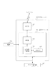
本実施例の図1は、高周波数の広域帯信号を用いるUWB通信方式を実装したUWBユニットのブロック図である。 FIG. 1 of the present embodiment is a block diagram of a UWB unit that implements a UWB communication system using a high-frequency wideband signal.
図においてUWBユニット100は無線通信システムを提供している。このUWB100が無線送受信機として無線送信機、または無線受信機となる。カプラ102はアンテナの役割を果たし、無線通信ネットワークを介してアナログ無線電波を送受信してUWBユニット100の送信部、または受信部となる。カプラ102には静電界、または誘導電界を送受信するための機能が実装されている。高周波の広帯域信号を電界結合で通信する方式を採用しているので、数センチ程度の近距離通信が可能である。数センチの距離を離れると信号が急速に減衰するためそれ以上の距離で他の電波と干渉することは少ない。この距離の設定は電界の信号の強さと有効閾値を設定することで任意に決めることができる。本実施例では5センチから電界信号の減衰が始まり、7センチが有効閾値となるように設定してあるとする。以下、減衰開始距離=5センチ、電界有効閾値=7センチと定義する。
In the figure, the UWB
RF部103はアナログ信号をデジタル信号に変復調する機能を備えている。RF部103はシンセサイザを備えていて、バンド、チャネルの周波数を識別し、周波数割り当てデータによるバンド、チャネルの制御をしている。送受信制御部104は送受信フレームの組み立て及び分解、プリアンブル付加及び検出、フレーム識別を行う。EEPROM105には本装置を一意に識別するための識別情報となる機器IDを格納する。機器IDは全ての装置間でユニークに決定される。これによりUWBユニット同士は一対一の通信を確立することができる。機器IDはMACアドレスで代用しても良い。
The
<実施例1>
以下、本発明の一実施形態としての無線通信システムを説明する。本システムはマルチファンクションプリンタ(Multi Function Printer、以後MFPと呼ぶ)と、デジタルカメラから構成される。このMFPは、画像読取装置と印刷装置が一体となっており、原稿台に載せられた原稿を読取部としての画像読取装置が読み取って、記録部としてのインクジェットプリンタである印刷装置が印刷を行う。またデジタルカメラは、撮影することでデジタル画像を生成可能であり、またここでは、デジタル画像を印刷するために、デジタル画像をMFPに送信できる。
<Example 1>
Hereinafter, a radio communication system as an embodiment of the present invention will be described. This system comprises a multi-function printer (hereinafter referred to as MFP) and a digital camera. In this MFP, an image reading device and a printing device are integrated. An image reading device serving as a reading unit reads a document placed on a document table, and printing is performed by a printing device that is an ink jet printer serving as a recording unit. . In addition, the digital camera can generate a digital image by photographing, and here, the digital image can be transmitted to the MFP in order to print the digital image.
本実施例1で説明するのは、次のようなケースである。最初に、デジタルカメラをユーザが操作してデジタル画像を送信するための状態に遷移させる。次にMFPがデジタルカメラからデジタル画像を受信して印刷を開始する。印刷をしている間は、デジタルカメラは印刷の状況を表示部に表示し、ユーザからの追加指示がある場合はその指示をMFPに送信する。MFPは印刷の状況をデジタルカメラに送信し、デジタルカメラからの指示を受けた場合はそれを実行する。また、MFPは同時に新たなデジタルカメラからの接続要求が無いかを監視する。 The first embodiment will be described in the following case. First, the user operates the digital camera to shift to a state for transmitting a digital image. Next, the MFP receives a digital image from the digital camera and starts printing. While printing, the digital camera displays the printing status on the display unit, and when there is an additional instruction from the user, transmits the instruction to the MFP. The MFP transmits the printing status to the digital camera, and executes it when receiving an instruction from the digital camera. The MFP also monitors whether there is a connection request from a new digital camera.
図5は、MFP500の概略構成を示すブロック図である。
FIG. 5 is a block diagram showing a schematic configuration of
MFP500は装置のメインの制御を行うメインボード501と、プリントデータを受け取ってインクの吐出制御を行うプリントキャリッジ502と、デジタルカメラなどの他デバイスとのデータ通信を行うUWBユニット524からなる。 The MFP 500 includes a main board 501 that performs main control of the apparatus, a print carriage 502 that receives print data and performs ink ejection control, and a UWB unit 524 that performs data communication with other devices such as a digital camera.
メインボード501においてCPU503は、システム制御部であり、MFP500の全体を制御する。ROM504は、CPU503が実行する制御プログラムや組み込みオペレーティングシステム(OS)プログラム等を格納する。本実施例では、ROM504に格納されている各制御プログラムは、ROM504に格納されている組み込みOSの管理下で、スケジューリングやタスクスイッチ等のソフトウエア制御を行う。
In the main board 501, a CPU 503 is a system control unit and controls the
RAM504は、SRAM(static RAM)等で構成され、プログラム制御変数等を格納し、また、ユーザが登録した設定値やMFP500の管理データ等を格納し、各種ワーク用バッファ領域、プリントバッファ領域が設けられている。
The RAM 504 is configured by an SRAM (static RAM) or the like, stores program control variables and the like, stores setting values registered by the user, management data of the
画像メモリ506は、DRAM(dynamic RAM)等で構成され、UWBユニット524を介して受信した画像データや、符号復号化処理部512で処理した画像データや、メモリカードコントローラ516を介して取得した画像データなどを蓄積する。
データ変換部507は、ページ記述言語(PDL)等の解析や、画像データからプリントデータへの変換などを行う。
The image memory 506 is configured by a DRAM (dynamic RAM) or the like, and the image data received via the UWB unit 524, the image data processed by the encoding / decoding processing unit 512, or the image acquired via the memory card controller 516. Accumulate data.
A
読取制御部508について説明する。読取部510が、CISイメージセンサ(密着型イメージセンサ)によって原稿を光学的に読み取る。次に電気的な画像データに変換した画像信号を、図示しない画像処理制御部を介して、2値化処理や中間調処理等の各種画像処理を施し、高精細な画像データを出力する。なお、本実施例では、読取制御部508は、原稿を搬送しながら読み取りを行うシート読取制御方式と、原稿台にある原稿をスキャンするブック読取制御方式の両制御方式に対応している。 The reading control unit 508 will be described. The reading unit 510 optically reads a document with a CIS image sensor (contact image sensor). Next, the image signal converted into electrical image data is subjected to various image processing such as binarization processing and halftone processing via an image processing control unit (not shown), and high-definition image data is output. In this embodiment, the reading control unit 508 corresponds to both a sheet reading control method for reading while conveying a document and a book reading control method for scanning a document on a document table.
操作部509はインタフェースパネル700上に配置され、ユーザが画像印刷データの決定や登録値の設定データ設定の登録動作を行う。表示部511は、LED(発光ダイオード)とLCD(液晶ディスプレイ)等によって構成される。これらを用いることで各種入力操作や、MFP500の動作状況、ステータス状況の表示等を行う事ができる。
符号復号化処理部512は、MFP500で扱う画像データ(MH、MR、MMR、JBIG、JPEG等)を符号復号化処理や、拡大縮小処理を行う。
An operation unit 509 is arranged on the interface panel 700, and the user performs an operation for determining image print data and registering setting data for registered values. The display unit 511 includes an LED (light emitting diode) and an LCD (liquid crystal display). By using these, various input operations, operation status of the
The code decoding processing unit 512 performs code decoding processing and enlargement / reduction processing on image data (MH, MR, MMR, JBIG, JPEG, etc.) handled by the
BlueTooth(商標登録)通信部513は、BlueToothによる通信を制御しており、通信I/F制御部や、ベースバンド部、RF部、アンテナ等から構成される。これにより、MFP500はBlueTooth通信規格で定められた通信を行うことができる。
The BlueTooth (registered trademark) communication unit 513 controls communication by BlueTooth, and includes a communication I / F control unit, a baseband unit, an RF unit, an antenna, and the like. Accordingly, the
データ蓄積部514はデータを蓄積するための部位である。本実施例では画像メモリ506でのDRAMではデータバックアップ用の領域を用意していないため、データ保存領域としてデータ蓄積部514を用意している。なお、このようなメモリ構成はこれに限定されるものではない。例えば画像メモリ506と共有させてもよいし、データ蓄積部514にデータのバックアップなどを行ってもよい。またデータ蓄積部514にデジタル画像などを保存し、印刷に用いたりもできる。また本実施例ではDRAMを用いているが、ハードディスクや不揮発性メモリ等を使用する場合もあるのでこの限りではない。 The data storage unit 514 is a part for storing data. In this embodiment, since the data backup area is not prepared in the DRAM in the image memory 506, the data storage unit 514 is prepared as a data storage area. Note that such a memory configuration is not limited to this. For example, it may be shared with the image memory 506, or data backup may be performed in the data storage unit 514. Also, a digital image or the like can be stored in the data storage unit 514 and used for printing. In this embodiment, a DRAM is used. However, this is not the case because a hard disk, a nonvolatile memory, or the like may be used.
給紙部515は印刷のための用紙を保持する事ができる部位である。記録制御部525からの制御で給紙部515から給紙を行うことができる。特に給紙部は複数種類の用紙を一つの装置に保持するために、複数の給紙部を用意する事ができる。そして記録制御部525により、どの給紙部から給紙を行うかの制御を行うことができる。 A paper feed unit 515 is a part capable of holding paper for printing. Paper can be fed from the paper feed unit 515 under the control of the recording control unit 525. In particular, the paper feeding unit can prepare a plurality of paper feeding units in order to hold a plurality of types of paper in one apparatus. The recording control unit 525 can control from which paper feeding unit the paper is fed.
メモリカードコントローラ516は、メモリカードを挿入して、USB通信規格で定められたプロトコルを通じてメモリカードのデータを送受信する。USB通信規格は、双方向のデータ通信を高速に行うことが出来る規格であり、1台のホスト(マスター)に対し、複数のハブまたはファンクション(スレーブ)を接続することが出来る。 The memory card controller 516 inserts a memory card and transmits / receives data of the memory card through a protocol defined by the USB communication standard. The USB communication standard is a standard capable of performing bidirectional data communication at high speed, and a plurality of hubs or functions (slaves) can be connected to one host (master).
メモリカード519はデータ記憶媒体であり、MFP500に接続する事が出来る。メモリカードには画像のデータやその他電子データを保存することができる。
A memory card 519 is a data storage medium and can be connected to the
プリントキャリッジ502はプリントヘッド制御部517と、プリントヘッド518から構成される。プリントキャリッジ502は主走査方向に移動しながらプリント動作を行う。プリントヘッド制御部517はフレキシブルケーブル522を介して記録制御部525からプリントデータを受信する。受信したデータに応じてプリントヘッド518から吐出するインクの制御を行う。 The print carriage 502 includes a print head control unit 517 and a print head 518. The print carriage 502 performs a printing operation while moving in the main scanning direction. The print head control unit 517 receives print data from the recording control unit 525 via the flexible cable 522. The ink ejected from the print head 518 is controlled according to the received data.
記録制御部525は、印刷される画像データに対し、図示しない画像処理制御部を介して、スムージング処理や記録濃度補正処理、色補正等の各種画像処理を施し、高精細な画像データに変換し、プリントヘッド制御部517に出力する。また、プリントヘッド制御部517を制御することにより、定期的にプリントヘッド制御部517の状態情報を取得する役割も果たす。 The recording control unit 525 performs various image processing such as smoothing processing, recording density correction processing, and color correction on the image data to be printed via an image processing control unit (not shown), and converts the image data into high-definition image data. And output to the print head controller 517. Further, by controlling the print head control unit 517, it also plays a role of periodically acquiring status information of the print head control unit 517.
UWBユニット524は、デジタルカメラなどの他デバイスとのデータ通信を行う通信部である。データをパケットに変換し、他デバイスにパケット送信を行う。逆に、外部の他デバイスからのパケットを、データに変換してCPU101に対して送信したりする。詳細は図1を用いて説明している。UWBユニット524はバスケーブル523を介してシステムバス521に接続されている。
The UWB unit 524 is a communication unit that performs data communication with other devices such as a digital camera. Data is converted into packets, and packets are sent to other devices. Conversely, packets from other external devices are converted into data and transmitted to the CPU 101. Details are described with reference to FIG. The UWB unit 524 is connected to the system bus 521 via the
上記構成要素503〜509、511〜516は、CPU503が管理するシステムバス521を介して、相互に接続されている。本実施例においては、読取部510と読取制御部508を用いて原稿を読取、データ変換部507を経て、データ蓄積部514に画像データを保存する事ができる。そして操作部509からの操作によって、画像データの印刷指示ができる。印刷指示を受けたら記録制御部525を用いてデータを変換して、プリントキャリッジ502によって印刷をすることができる。
The components 503 to 509 and 511 to 516 are connected to each other via a system bus 521 managed by the CPU 503. In this embodiment, a document can be read using the reading unit 510 and the reading control unit 508, and the image data can be stored in the data storage unit 514 via the
図6はMFP500の外観および内部構成の透視図である。メインボード501がMFP筐体の右側に取り付けられている。メインボード501とプリントキャリッジ502を結ぶフレキシブルケーブル522によって印刷データが送信されている。フレキシブルケーブル522はプリントキャリッジ502がシャフト600上を往復する最中もデータを送受信できる。メインボード501とUWBユニット524はバスケーブル523を介して接続されており、高速にデータを通信することができる。UWBユニットは通信可能距離が短いため、できるだけMFP筐体の表面のUWB無線機器置き場702に近い場所に設置する。少なくとも電界有効距離よりも短い距離になるようにする。読取部510に原稿をセットして、原稿蓋905を閉めてから原稿を読み取る。その他、印刷シートを搬送する不図示の搬送部等がある。
FIG. 6 is a perspective view of the external appearance and internal configuration of the
図7は、図6で説明したインタフェースパネル700の詳細構成を表した図である。インタフェースパネル700は表示部701、UWB無線機置き場702、操作部703から構成される。表示部701はドットマトリクスLCDであり、印刷に用いる画像データを可視化したり、ユーザ設定状態を表示したり、各種作業状況を設定したりする。
UWB無線機置き場702はMFP500がデジタルカメラなどの外部機器とデータを送受信するための接触部である。UWB無線機置き場の内部にはUWBユニットがあり、電界による信号が発信されている。UWBユニットを装着したデジタルカメラなどの外部機器をUWB無線機置き場に近接または接触させることで、お互いが電界による信号を送受信して接続を確立し、通信を行うことができる。
FIG. 7 is a diagram showing a detailed configuration of the interface panel 700 described with reference to FIG. The interface panel 700 includes a
The UWB
操作部703はユーザがMFP500を操作するためのキーから構成されている。十字キー705は表示部のカーソル移動などに用いる。セットキー704は設定入力キーである。スタートキー706は印刷やコピーなどの動作をスタートさせる時などに用いる。ストップキー707は印刷やコピーなどの動作をストップさせる時などに用いる。
The operation unit 703 includes keys for the user to operate the
図15は、デジタルカメラ1500の概略構成を示すブロック図である。 FIG. 15 is a block diagram illustrating a schematic configuration of the digital camera 1500.
デジタルカメラ1500において、CPU1501は、システム制御部であり、デジタルカメラ1500の全体を制御する。ROM1502は、CPU1501が実行する制御プログラムや組み込みオペレーティングシステム(OS)プログラム等を格納する。本実施例では、ROM1502に格納されている各制御プログラムは、ROM1502に格納されている組み込みOSの管理下で、スケジューリングやタスクスイッチ等のソフトウエア制御を行う。
In the digital camera 1500, a CPU 1501 is a system control unit and controls the entire digital camera 1500. The
RAM1503は、SRAM(static RAM)等で構成される。このRAM1503はプログラム制御変数等を格納し、またユーザが登録した設定値やデジタルカメラ1500の管理データ、デジタルカメラ1500の機器ID等を格納し、また各種ワーク用バッファ領域が設けられている。画像メモリ1504は、DRAM(dynamic RAM)等で構成され、撮像部1509を介して撮像された画像データを一時的に蓄積したり、メモリカードから読み込んだ画像を一時的に蓄積したりする。また、UWBユニットを用いて画像を送信する際にも送信用バッファとして使用する。データ変換部1505は、画像データの変換などを行う。
The
BlueTooth(商標登録)通信部1506は、BlueToothによる通信を制御しており、通信I/F制御部や、ベースバンド部、RF部、アンテナ等から構成される。これにより、デジタルカメラ1500はBlueTooth通信規格で定められた通信を行うことができる。操作部1507は、ユーザがメモリカード内の写真を選択してUWBユニットを介してデータ転送指示を行う際に使用したり、その他、撮影指示や、各種設定指示を行ったりする。
A BlueTooth (registered trademark) communication unit 1506 controls communication by BlueTooth, and includes a communication I / F control unit, a baseband unit, an RF unit, an antenna, and the like. Thereby, the digital camera 1500 can perform communication defined by the BlueTooth communication standard. The
表示部1508は、ドットマトリクスLCDであり、印刷に用いる画像データを可視化したり、ユーザ設定状態を表示したり、各種作業状況を設定したりする。
A
撮像部1509は、デジタルカメラ1500が画像を撮影するための部位であり、レンズ、画像センサ、シャッターなどから構成される。
The
メモリカードコントローラ1510は、メモリカードを挿入して、USB通信規格で定められたプロトコルを通じてメモリカードのデータを送受信する。USB通信規格は、双方向のデータ通信を高速に行うことが出来る規格であり、1台のホスト(マスター)に対し、複数のハブまたはファンクション(スレーブ)を接続することが出来る。メモリカード1512はデータ記憶媒体であり、デジタルカメラ1500に接続する事が出来る。メモリカードには画像のデータやその他電子データを保存することができる。
The
UWBユニット1511は、MFPやプリンタなどの他デバイスとのデータ通信を行う通信部である。データをパケットに変換し、他デバイスにパケット送信を行う。逆に、外部の他デバイスからのパケットを、データに変換してCPU1501に対して送信したりする。詳細は図1を用いて説明している。 The UWB unit 1511 is a communication unit that performs data communication with other devices such as an MFP and a printer. Data is converted into packets, and packets are sent to other devices. Conversely, packets from other external devices are converted into data and transmitted to the CPU 1501. Details are described with reference to FIG.
上記構成要素1502〜1511はCPU1501が管理するシステムバス1514を介して、相互に接続されている。本実施例においては、撮像部1509を用いて画像データを撮影し、データ変換部1505を経て、メモリカード1512に画像データを保存する事ができる。そして操作部1507からの操作によって、画像データの転送指示ができる。転送指示を受けたらUWB1511を用いてデータをMFPなどの他デバイスに送信して印刷をすることができる。
The
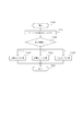
図17は、図1で示したUWBユニットの状態遷移を表したUWBユニット状態遷移図である。1701は主動モードのデバイスの状態遷移を表したものであり、1702は受動モードのデバイスの状態遷移を表したものである。ここでいう主動モードとは送信機状態のことであり、データ送受信の必要性が生じたデバイスのことである。受動モードとは受信機状態のことであり、主動モードのデバイスからデータ送受信の開始信号を受け取るデバイスのことである。具体的には、デジタルカメラからMFPに対して印刷要求をして、MFPは画像データを受け取って印刷を行う場合は、デジタルカメラが主動モードになり、MFPが受動モードとなる。 FIG. 17 is a UWB unit state transition diagram showing the state transition of the UWB unit shown in FIG. 1701 represents the state transition of the device in the main mode, and 1702 represents the state transition of the device in the passive mode. The main operation mode here refers to a transmitter state, which is a device in which the necessity of data transmission / reception has occurred. The passive mode is a receiver state, and is a device that receives a data transmission / reception start signal from a device in the main mode. Specifically, when the digital camera issues a print request to the MFP and the MFP receives image data and performs printing, the digital camera is in the main operation mode and the MFP is in the passive mode.
1703はパワーオフ状態を表し、電源が入っていない状態のことである。この状態で、電源が投入されると、1704スリープ状態に遷移する。1704はスリープ状態を表し、電源は入っているが、UWBユニット100は動作していない状態である。この状態で、周期的、または何らかのトリガによって1705サーチ状態に遷移する。1705はサーチ状態を表し、後述する1709接続要求状態にあるデバイスからの接続要求信号を受信できる状態である。この状態で接続要求信号を受信すると1706接続要求受信状態に遷移する。または、一定周期時間が経過するか、何らかのトリガによって1704スリープ状態に遷移する。1706は接続要求受信状態を表し、1701主動モードにあるデバイスからの主動機IDを記憶してから、1707接続許可送出状態に遷移する。1707は接続許可送出状態を表し、1709接続要求状態にあるデバイスに対して接続許可信号を送出している状態である。この状態で受信確認応答信号を受信すると1708接続中状態に遷移する。1708は接続中状態を表し、1711接続中状態にあるデバイスとパケットを用いて通信可能な状態である。この状態で、1711接続中状態にあるデバイスから切断信号を受信するか、自らが切断信号を送出するか、または何らかのエラーにより接続を確立できない状況になったら1705サーチ状態に遷移する。
一方、主動モードにあるデバイスの状態遷移について述べる。1709は接続要求状態を表し、データの送受信の必要性が生じたために、接続要求信号を送出し続けている状態を表す。この状態で、所定の時間だけ接続要求信号を送出し続け、接続許可信号を受信できなかった場合は1705サーチ状態に遷移する。接続許可信号を受信できた場合は1710接続許可受信状態に遷移する。1710は接続許可受信状態を表し、接続許可信号を受信したら1702受動モードにあるデバイスからの受動機IDを記憶してから受信確認応答信号を送出してから1711接続中状態に遷移する。1711は接続中状態を表し、1708接続中状態にあるデバイスとパケットを用いて通信を行うことができる。この状態で、1708接続中状態にあるデバイスから切断信号を受信するか、自らが切断信号を送出するか、または何らかのエラーにより接続確立ができない状況になったら1705サーチ状態に遷移する。
On the other hand, the state transition of the device in the main mode will be described.
図18は、図1で示したUWBユニット100が省電力モードになっている場合の状態遷移を表した図である。UWBユニット100は1705サーチ状態になっている方が、1704スリープ状態になっている時よりも多くの電力を消費する。そこで省電力モードにすることで消費電力を抑えることができる。省電力モードでは、1801に表すT1時間だけサーチ状態に遷移し、1802に示すT2時間だけスリープ状態に遷移する。T1時間は接続要求信号が受信できるだけの時間以上に設定する。T2時間は適用する装置ごとに任意に設定できるが、T2時間が長ければユーザが1701主動モードにあるデバイスを近接させてから1702受動モードにあるデバイスが反応するまでの時間が長くなる。デバイス毎に適用用途に応じてT2時間は設定するのが良い。
FIG. 18 is a diagram illustrating state transition when the
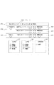
図19、図20は、UWBユニット同士が送受信に用いるパケットのフォーマットを表した図である。 19 and 20 are diagrams showing packet formats used by UWB units for transmission and reception.
図19はUWBユニットが通信を行う際に送受信に用いるマネージメントフレームの構成を表した図であり、マネージメントパケット1900はUWBユニット同士が接続を確立するために用いるパケットである。プリアンブル1901はフレーム送信の開始を認識させ、同期を取るタイミングを与えるための信号である。ヘッダ1902は1904から1909に示すデータで構成される。1904は主動モードにあるデバイスの機器IDを格納する。1905は受動モードにあるデバイスの機器IDを格納する。1905の機器IDは図1で前述したEEPROM105に格納されているIDのことである。1906はコマンドIDであり、接続の確立から切断までに用いるマネージメントコマンドをセットできる。ここでは具体的に接続要求、接続許可、受信確認応答、切断の4つの信号を表す。1907にはそれぞれのコマンドで用いられるパラメータをセットすることができる。1908にはパケット番号が格納されており、これは今回の接続処理が始まってから何番目のパケットかを示す通し番号である。1903は付加情報を表しており、必要に応じてマネージメントパケットに付加した情報を追加しても良い。
FIG. 19 is a diagram showing the configuration of a management frame used for transmission / reception when UWB units communicate, and a management packet 1900 is a packet used for establishing a connection between UWB units. A
図19のACKパケット1910は全てのコマンドに対する返信に用いるパケットである。例外的にACKが必要でないパケットも幾つか有るが、基本的に全てのパケットに対してACKパケットがセットで返信される。コマンドID1911にはACKがセットされる。対応パケット番号1912には、どのパケットに対応するのか、1908または後述の2008に記載されるパケット番号がセットされる。
An ACK packet 1910 in FIG. 19 is a packet used for a reply to all commands. Although there are some packets that do not require ACK exceptionally, ACK packets are basically returned as a set for all packets. ACK is set in the command ID 1911. In the
図20はUWBユニットが通信を行う際に送受信に用いるデータフレームの構成を表した図であり、データパケット2000はUWBユニット同士が接続を確立した後に、データを送受信する際に用いるパケットである。プリアンブル2001はプリアンブル1901と同等の機能をもつ。ヘッダ2002はコマンドID2006を除いてヘッダ1902と同様である。コマンドID2006はDATA_No.xxを表すコマンドがセットされる。xxの部分はデータパケットの通し番号が記載されている。2003はデータボディを表しており、プロトコルコマンドID2010と付加情報2011から構成される。プロトコルコマンドIDは画像転送コマンドや、画像転送終了コマンド、ステータス送信、中止要求コマンドなど、接続を確立した後に用いる全てのコマンドが定義されている。そして付加情報2011では、プロトコルコマンドIDで指定されたコマンドに対応する付加情報が記載されている。例えば、画像転送コマンドの時は付加情報2011には実際の画像情報がセットされ、ステータス送信の場合は現状のデバイスのステータスが送信される。
FIG. 20 is a diagram showing the configuration of a data frame used for transmission / reception when the UWB units perform communication. A data packet 2000 is a packet used when transmitting / receiving data after the UWB units establish a connection. The
図21は、UWBユニット100を搭載しているデジタルカメラ1500とMFP500が通信を行って画像データを印刷する場合の、接続確立の際のシーケンスを表した図である。2100から2108まではシーケンス、及び動作を表しており、2109から2115まではデジタルカメラ1500及びMFP500が図17のUWBユニット状態遷移図に従って状態遷移する状態を表している。最初にサーチ状態にあるデジタルカメラを、ユーザが操作して印刷する画像を選択して印刷開始を指示する操作を行ってから、デジタルカメラをUWB無線機器置き場702に近接させる。するとデジタルカメラは接続要求状態2113に遷移し、マネージメントパケット1900に従った接続要求信号2100が送出される。接続要求信号は接続許可信号が返信されるか、所定の時間が経過するまで送出信号2101、2104というように送出されつづける。
FIG. 21 is a diagram illustrating a sequence for establishing a connection when the digital camera 1500 on which the
このとき、MFPが省電力モードであった場合は図18のT1時間1801、T2時間1802に従ってそれぞれサーチ状態、スリープ状態を繰り返す状態である2109に遷移している。T1時間1801でサーチ状態になったときに接続要求を受け付けることができるので、2102で接続要求信号を受信する。送信要求信号を受け取ったら接続要求受信状態2110に遷移する。次にMFPは2103で主動機ID1904を記憶する。接続を許可できる主動機ID1904であったならば接続許可信号2105を送出する。デジタルカメラは接続許可信号2105を受信すると、接続許可受信状態に遷移し、2107で受動機ID1905を記憶し、受信確認応答信号2108を送信して接続中状態2115に遷移する。受信確認応答信号2108を受信したMFPは接続中状態2112に遷移する。デジタルカメラ、MFPが共に接続中状態に遷移することで接続を確立することができ、これより後はデータパケット2000を用いて相互にデータを送受信することができる。
At this time, if the MFP is in the power saving mode, transition is made to 2109 which is a state in which the search state and the sleep state are repeated in accordance with the
なお、以上の説明ではマネージメントパケット1900に機器のIDが格納されているので、2103では、2102において受信した接続要求信号に含まれる主動機ID1904を記憶していた。しかし本発明はこれに限らず、マネージメントパケット1900に機器のIDが格納されない場合であってもよい。この場合、MFPは2102において接続要求信号を受信すると、デジタルカメラに対してIDを要求する信号を送り、そして、この信号を受信したデジタルカメラが主動機ID1904をMFPに送信すればよい。2103において、このような手順で送信されたIDを記憶する場合であっても、上述の図21と同様の処理を行うことができる。
In the above description, since the device ID is stored in the
図22は、UWBユニット100を搭載しているデジタルカメラ1500とMFP500が通信を行って画像データを印刷する場合の、接続確立した後に画像データを転送する際のシーケンスを表した図である。通常は画像データのサイズはデータパケットの最大サイズよりも大きいので、一枚の画像は複数のパケットに分割して送信される。2200は分割された画像のうちN番目の画像であることを表す画像転送Nである。データパケットはACK2202が返信されるまでMFPに対して送信され続ける。2200が何らかの原因でMFPまで到達しなかった場合でも、ACK2202が返信されるまで2201以降も送信されつづけるので問題は無い。2201は送信され続けている例を表している。ACK2202が返信されるとデジタルカメラは次のデータパケットである、2203の画像転送N+1を送信する。MFPは画像転送N+1を受信したら同様にACK2204を返信する。図22はプロトコルコマンドID2010が画像転送コマンドの場合を例に挙げたが、画像転送終了コマンド、ステータス送信、中止要求コマンドなどの場合でも同様である。また、無線通信においては、一部の例外を除いては基本的に正常に受信できたことを表すACKを返信することになっている。これ以降に示すシーケンスではACKは省略することにする。
FIG. 22 is a diagram illustrating a sequence when image data is transferred after connection is established when the digital camera 1500 mounted with the
図23、図24は、次のケースのシーケンス図を表したものである。簡単に説明すると、最初にデジタルカメラ1からMFPに対して印刷したい画像データを送信する。次にMFPで受信した画像データの印刷を開始する。印刷中に、MFPからデジタルカメラ1に印刷の状況を送信する。デジタルカメラ1では印刷の状況を表示部に表示する。同時にユーザからの指示も監視する。MFPでは、デジタルカメラ1以外に接続要求を送出しているデジタルカメラが存在しないかを探す。あったならば新しいデジタルカメラ2との通信を開始する。
23 and 24 show sequence diagrams of the following case. Briefly, first, image data to be printed is transmitted from the digital camera 1 to the MFP. Next, printing of image data received by the MFP is started. During printing, the printing status is transmitted from the MFP to the digital camera 1. The digital camera 1 displays the printing status on the display unit. At the same time, instructions from the user are monitored. The MFP searches for a digital camera sending a connection request other than the digital camera 1. If there is, communication with the new
図23は、UWB無線機器同士が接続を確立し、データを送受信し、ステータスを送受信し、且つ新たな機器からの信号をサーチしている際のシーケンスを表した図である。 FIG. 23 is a diagram illustrating a sequence when UWB wireless devices establish a connection, transmit / receive data, transmit / receive status, and search for a signal from a new device.
上記説明した概要を、図23で始まるシーケンスを用いて詳細に説明する。まず2300では、図21に示すシーケンスでMFPとデジタルカメラ1の接続を確立する。このとき、デジタルカメラ1が主動モード1701であり、MFPが受動モード1702になる。次に、2301、2302では、図22に示すシーケンスでデジタルカメラ1からMFPに対して所望の画像データを送信する。2303では印刷状況をステータスとしてデジタルカメラ1に送信する。送信する情報には、印刷の残り時間、MFPのインク残量、エラーや警告がある場合にはユーザに対するメッセージなど、様々な情報が考えられる。2303は定期的に送信しても良いし、ステータスの変更があった毎に送信しても良い。2304ではユーザからの指示をMFPに送信する。例えばユーザによってデジタルカメラ1の操作部を用いて印刷中断操作がなされた場合には、デジタルカメラ1からMFPに対して変更命令を送信する。 The outline described above will be described in detail using a sequence starting from FIG. First, in 2300, the connection between the MFP and the digital camera 1 is established in the sequence shown in FIG. At this time, the digital camera 1 is in the main operation mode 1701, and the MFP is in the passive mode 1702. Next, in 2301 and 2302, desired image data is transmitted from the digital camera 1 to the MFP in the sequence shown in FIG. In 2303, the printing status is transmitted to the digital camera 1 as a status. The information to be transmitted includes various information such as the remaining printing time, the remaining ink amount of the MFP, and a message to the user when there is an error or warning. 2303 may be transmitted periodically or may be transmitted every time the status is changed. In 2304, an instruction from the user is transmitted to the MFP. For example, when a print interruption operation is performed by the user using the operation unit of the digital camera 1, a change command is transmitted from the digital camera 1 to the MFP.
次に2305では、MFPが新しいデジタルカメラが存在しないかを探すのだが、これを図17のUWBユニット状態遷移図をふまえて説明する。まず、MFPはデジタルカメラとデータを送受信しているので、接続中状態1708である。1708では一対一の接続が確立されているために新しいデジタルカメラが近接されてもMFPは応答することができない。そこで、一時的にサーチ状態1705に遷移する。遷移する際には、2103で記憶した主動機IDを記憶したままにしておいたままにする。または、主動機IDはRAM505の別領域に保存しておいても良い。サーチ状態1705になったMFPは所定の時間だけサーチ状態を保つことで接続要求状態1709にある新たなデジタルカメラを探すことができる。新たなデジタルカメラが見つからなかった場合には、擬似的に接続要求受信状態1706に遷移し、保存しておいた主動機IDを用いることで接続許可送出状態1707に遷移し、受信確認応答信号2108が無くても接続中状態1708に遷移させる。そうすることでMFPは再びデジタルカメラ1とステータス2303や変更命令2304を送受信することができる。
Next, in 2305, the MFP searches for a new digital camera, which will be described based on the UWB unit state transition diagram of FIG. First, since the MFP transmits / receives data to / from the digital camera, it is in the connected state 1708. In 1708, since a one-to-one connection is established, the MFP cannot respond even if a new digital camera comes close. Therefore, the
MFPが接続中状態1708と、サーチ状態1705の間を周期的に行き来することを、印刷中の期間、または新たなデジタルカメラ2が見つかるまで繰り返す(2306)。新たなデジタルカメラ2が見つかった場合は図24に示すシーケンスに遷移する。2305でMFPが新しいデジタルカメラが存在しないかを探すタイミングとしては、2303ステータス信号や2304変更命令信号が発生しない時間が望ましい。また、探している時間としては、次回の2303ステータス信号や2304変更命令信号が発生するであろう予測時間よりも短く設定するのが望ましい。
The MFP periodically goes back and forth between the connected state 1708 and the
図24は、UWB無線機器同士が接続を確立し、データを送受信し、ステータスを送受信し、且つ新たな機器からの信号をサーチしている際に、新たな機器からの信号が見つかった場合のシーケンスを表した図である。MFPは接続要求信号2400を受信して、2400を送信した機器が接続を許可できる主動機IDであったならば接続許可信号2401を送出する。同時にMFPは2400中の主動機IDを記憶する。更に2402でデジタルカメラ1に対して切断信号を送出する。切断信号2402に対するACKがデジタルカメラ1から送信されたらMFPはデジタルカメラ1の主動機IDを破棄する。デジタルカメラ2は2401を受信したら、2401内の受動機IDを記憶して接続中状態に遷移してから2404の画像転送信号1を送出する。
FIG. 24 shows a case where a UWB wireless device establishes a connection, transmits / receives data, transmits / receives a status, and searches for a signal from a new device, and finds a signal from the new device. It is a figure showing a sequence. The MFP receives the connection request signal 2400, and transmits a connection permission signal 2401 if the device that has transmitted 2400 has a main motor ID that can permit the connection. At the same time, the MFP stores the main motive ID in 2400. Further, at 2402, a disconnection signal is sent to the digital camera 1. When an ACK for the disconnect signal 2402 is transmitted from the digital camera 1, the MFP discards the main motive ID of the digital camera 1. When the
以上の図23、図24に記載するフローを実施することで、MFPはデジタルカメラ1からの画像を受信して印刷中であるとき、デジタルカメラ1と通信してステータスやユーザの操作を送受信することができる。それと同時に新たなデジタルカメラ2が近接されていることを検知することもできる。
By performing the flow described in FIGS. 23 and 24, when the MFP receives an image from the digital camera 1 and is printing, the MFP communicates with the digital camera 1 to transmit and receive statuses and user operations. be able to. At the same time, it can be detected that a new
また図23において、2300の接続確立から2302の画像転送信号nまでの間は、MFPは新たなデジタルカメラの検知を行わず、2306を繰り返している間に検知を行う構成にしている。こうすることで、画像を転送している間は他デバイスの近接を無視できるので、確実に画像を転送することができる。
In FIG. 23, the MFP is configured not to detect a new digital camera from the establishment of the
図25、図26、図27は、次のケースのシーケンス図を表したものである。簡単に説明すると、最初にデジタルカメラからMFPに対して印刷したい画像データを送信する。次にMFPで受信した画像データの印刷を開始する。画像はサイズの大きい画像や複数毎の場合、画像転送をしている最中にMFPの受信バッファがメモリフルになって一時的に画像データを受け付けられなくなる。その他、MFPの紙詰まりやインク切れなど、何らかの原因でMFPが画像を受けられなくなったとき、デジタルカメラに対して中断信号を送出する。そして、中断原因が解消したらデータ送信を再開する。 25, 26, and 27 show sequence diagrams of the following case. Briefly, first, image data to be printed is transmitted from the digital camera to the MFP. Next, printing of image data received by the MFP is started. In the case of a large image or multiple images, the MFP reception buffer becomes full of memory during image transfer, and image data cannot be received temporarily. In addition, when the MFP cannot receive an image for some reason, such as a paper jam or out of ink, an interruption signal is sent to the digital camera. When the cause of interruption is resolved, data transmission is resumed.
図25はMFPとデジタルカメラが接続を確立し、データを送受信し、MFPから中断信号を送る場合のシーケンスを表した図である。まず2500では、図21に示すシーケンスでMFPとデジタルカメラの接続を確立する。このとき、デジタルカメラが主動モード1701であり、MFPが受動モード1702になる。次に、2501では、図22に示すシーケンスでデジタルカメラ1からMFPに対して所望の画像データを送信する。このケースでは、n枚の画像を送信したい場合であり、2502でn−3枚目までの送信が完了する。ここでMFPの受信バッファがメモリフルをおこしてそれ以上画像データを受信できない状態になったとする。すると、MFPはデジタルカメラに対して中断信号を送出する。 FIG. 25 is a diagram showing a sequence when the MFP and the digital camera establish a connection, transmit / receive data, and send an interruption signal from the MFP. First, in 2500, a connection between the MFP and the digital camera is established in the sequence shown in FIG. At this time, the digital camera is in the main mode 1701 and the MFP is in the passive mode 1702. Next, in 2501, desired image data is transmitted from the digital camera 1 to the MFP in the sequence shown in FIG. In this case, it is a case where n images are desired to be transmitted, and the transmission up to the n-3th image is completed in 2502. Here, it is assumed that the reception buffer of the MFP is full and the image data cannot be received any more. Then, the MFP sends an interruption signal to the digital camera.
デジタルカメラが画像データ転送を中断して再開を待つ休止モードには2種類あり、定期監視モードと、電源断モードである。定期監視モードはデジタルカメラの通信部は動作可能であり、つまりは通信可能な状態になっているが、それ以外の部分は省電力のために休止している状態のことを示す。この状態の時には通信部が再開要求信号を受信すればすぐに画像転送を再開することができる。一方、電源断モードはデジタルカメラの通信部が通信不可能な状態になっており、それ以外の部分も省電力のために休止している状態のことを示す。この状態の時には通信部は再開要求信号を受信することはできず、自らのタイマによって休止状態から起床しなければならない。 There are two types of sleep modes in which the digital camera interrupts image data transfer and waits for resumption, a regular monitoring mode and a power-off mode. The periodical monitoring mode indicates that the communication unit of the digital camera is operable, that is, in a state where communication is possible, but the other parts are in a state of being suspended for power saving. In this state, the image transfer can be resumed as soon as the communication unit receives the resume request signal. On the other hand, the power-off mode indicates that the communication unit of the digital camera is in a state incapable of communication, and other parts are in a state of being suspended for power saving. In this state, the communication unit cannot receive the restart request signal and must wake up from the sleep state by its own timer.
図26は、デジタルカメラを定期監視モードにした際の、画像転送を再開するシーケンスを表した図である。2503で中断信号を受信したデジタルカメラは定期監視モードになっている。デジタルカメラは再開要求信号2600を受信したら定期監視モードから起床して画像データを送信できる状態に復帰する。復帰が終了したら再開許可信号2601を送出してMFPに対して再開許可信号2600を送出する。次に先ほど送出が完了していなかった2602画像転送信号(n−3枚目)から再開して、2603画像転送信号(n枚目)まで転送が終了したら2604切断信号を送出して本シーケンスを終了する。 FIG. 26 is a diagram showing a sequence for restarting image transfer when the digital camera is set to the regular monitoring mode. The digital camera that has received the interruption signal in 2503 is in the regular monitoring mode. When the digital camera receives the resume request signal 2600, it wakes up from the regular monitoring mode and returns to a state where image data can be transmitted. When the return is completed, a restart permission signal 2601 is sent and a restart permission signal 2600 is sent to the MFP. Next, the transmission is resumed from the 2602 image transfer signal (n-3th sheet) that has not been transmitted previously, and when the transfer is completed up to the 2603 image transfer signal (nth sheet), a 2604 disconnect signal is transmitted to execute this sequence. finish.
図27は、デジタルカメラを電源断モードにした際の、画像転送を再開するシーケンスを表した図である。2503で中断信号を受信したデジタルカメラは電源断モードになっている。電源断モードにする際には、2503中断信号において、デジタルカメラが電源断モードから復帰する時間を設定しておく。2700では、その時間が経過したら2701の再開要求信号を送出する。MFPは、再開が可能な状態であれば、2702再開許可信号を送出して画像データの送信を再開する。再開が不可能な状態であれば、再び2503の中断信号を送出してデジタルカメラを電源断モードにして2700から繰り返す。 FIG. 27 is a diagram showing a sequence for restarting image transfer when the digital camera is set to the power-off mode. The digital camera receiving the interruption signal in 2503 is in a power-off mode. When the power-off mode is set, a time for the digital camera to return from the power-off mode is set in the 2503 interruption signal. In 2700, when the time elapses, a restart request signal 2701 is transmitted. If the MFP is in a resumable state, the MFP restarts the transmission of the image data by sending a 2702 restart permission signal. If the restart is impossible, the interruption signal 2503 is sent again to put the digital camera in the power-off mode, and the process is repeated from 2700.
電源断モードの方が定期監視モードよりも消費電力を低く抑えることができるため、印刷を中断して待つ場合は有利である。しかし、MFPからの再開要求信号が受けられないため、一定の間隔でMFPの状態を監視する必要がある。そこで、本発明ではMFPとデジタルカメラの画像データ転送が中断する原因に応じて電源断モードと定期監視モードを切り替えることにする。具体的には、MFPの再開時間が予測できる中断原因か否かにより切り替える。再開時間が予測できる中断原因としては、受信バッファのメモリフル、プリントヘッドの温度が異常に上昇する昇温エラー、プリントヘッドのクリーニングなどを行う回復中状態などが上げられる。また、再開時間が予測できない中断原因としては、紙詰まり、インクタンク交換、記録紙無しエラーなどが挙げられる。再開時間が予測できる中断原因が発生したときには、デジタルカメラに対して、電源断モードで中断するように指示する。再開時間が予測できない中断原因が発生したときには、デジタルカメラに対して定期監視モードで中断するように指示する。そうすることで、再開時間が予測可能な中断原因の時にはデジタルカメラの消費電力を抑える状態で中断でき、再開時間が予測不可能な中断原因の時には中断原因が解消されたときに速やかに画像転送を再開することができる。 In the power-off mode, the power consumption can be kept lower than in the regular monitoring mode, so it is advantageous to interrupt printing and wait. However, since the restart request signal from the MFP cannot be received, it is necessary to monitor the state of the MFP at regular intervals. Therefore, in the present invention, the power-off mode and the regular monitoring mode are switched according to the cause of interruption of image data transfer between the MFP and the digital camera. Specifically, the switching is performed depending on whether or not the cause of interruption is a predictable restart time of the MFP. Reasons for the interruption that can be predicted for the restart time include a memory full in the reception buffer, a temperature rise error in which the temperature of the print head abnormally rises, a recovery state in which the print head is being cleaned, and the like. In addition, the cause of the interruption in which the restart time cannot be predicted includes a paper jam, ink tank replacement, and no recording paper error. When a cause of interruption that can predict the restart time occurs, the digital camera is instructed to interrupt in the power-off mode. When a cause of interruption occurs where the restart time cannot be predicted, the digital camera is instructed to interrupt in the regular monitoring mode. By doing so, it can be interrupted while reducing the power consumption of the digital camera when the cause of the interruption is predictable, and when the cause of the interruption is resolved when the interruption time is unpredictable, the image can be transferred quickly. Can be resumed.
<実施例2>
以下、本発明の一実施形態としての無線通信システムを説明する。本システムでは、UWBユニットを搭載したメモリカード、デジタルカメラ等のデバイスと、そのデバイスと実施例1で説明した近接無線通信が可能なメモリリーダから構成される。なお、メモリカードの場合は、その内容を読書きすることができる。このような構成において、特にメモリリーダのUWBユニットが移動する場合の実施例を示す。
<Example 2>
Hereinafter, a radio communication system as an embodiment of the present invention will be described. This system includes a device such as a memory card or a digital camera equipped with a UWB unit, and the memory reader capable of the close proximity wireless communication described in the first embodiment. In the case of a memory card, the contents can be read and written. In such a configuration, an embodiment in the case where the UWB unit of the memory reader moves is shown.
本実施例2で説明するのは、次のようなケースである。最初に、メモリカードをメモリリーダにセットする。このメモリリーダの置き場には複数のメモリカードを任意の場所に置くことができる。またメモリリーダはメモリカードが置かれた平面上のXY方向にUWBユニットを走査してメモリカードを探索する機構をもっている。メモリカードの位置にUWBユニットを移動させて、メモリカード内のデータを送受信する。 The following case will be described in the second embodiment. First, the memory card is set in the memory reader. A plurality of memory cards can be placed in any place in the memory reader. The memory reader has a mechanism for searching for a memory card by scanning the UWB unit in the X and Y directions on the plane on which the memory card is placed. The UWB unit is moved to the position of the memory card to transmit / receive data in the memory card.
図2は、メモリリーダ200の概略構成を表すブロック図である。UWBユニット201は、メモリカードなどの他デバイスとのデータ通信を行う通信部である。データをパケットに変換し、他デバイスにパケット送信を行う。逆に、外部の他デバイスからのパケットを変換して、データ蓄積部204に蓄積したりする。詳細は図1を用いて説明している。
FIG. 2 is a block diagram illustrating a schematic configuration of the memory reader 200. The
本実施例では、UWBユニット201は可動式になっている。CPU202は、システム制御部であり、メモリリーダ200の全体を制御する。駆動制御部203は可動式のUWBユニット201の駆動を制御する。データ蓄積部204は、UWBユニット201を介して送受信されるデータをバッファする。送信の際にはデータ蓄積部204にデータを記憶しておき、逐次UWBユニットを通じて送信する。受信の際にはUWBユニットを通じて受信したデータを蓄積し、データ変換部205またはCPU202で処理されるのを待つ。データ変換部205ではホストデバイスとメモリカードリーダ200との間で所望のデータに変換して通信を行う。ホストデバイスI/F206はPCなどのホストデバイスとの論理的なI/Fを提供する。
In this embodiment, the
図3は、メモリリーダ200の外観図である。UWB無線機器置き場300はメモリカードやデジタルカメラなど、UWBユニット100を搭載したUWB無線機器を載せる場所である。UWB無線機器置き場300においたデバイスは、デバイス側で送信指示を行うか、メモリリーダが接続されたPCを用いて受信指示を行うことで、デバイス側からPC側へデータを転送することができる。また、逆の指示を行うことでPC側からデバイス側へもデータを転送することができる。PCなどのホストデバイスとはコネクタ301を物理的なI/Fとして接続される。
FIG. 3 is an external view of the memory reader 200. The UWB wireless device storage place 300 is a place where UWB wireless devices equipped with the
図4は、メモリリーダ200の内部透視図である。400はXY駆動ユニットであり、XY方向への移動や、加減速の制御を行う。このXY駆動ユニット400によりXY駆動ユニット400はXシャフト401、Yシャフト402上をXY方向に自由に移動することができる。またXY駆動ユニット400上にはUWBユニットが搭載されており、このUWBユニットはUWB無線機器置き場300上に置かれたUWB無線機器と通信を行う。この通信の際には、減衰開始距離、及び電界有効閾値といったUWBユニットの信号の信号間隔を考慮して、なるべくUWB無線機器置き場300の表面に近い場所を駆動するようにする。この通信で得られたデータはフレキシブルケーブル403を介してメインボード404に転送される。このフレキシブルケーブル403は通信を行ったデータの送受信の他にも、XY駆動ユニットの制御信号の送受信、電源の供給のために用いられる。 FIG. 4 is an internal perspective view of the memory reader 200. Reference numeral 400 denotes an XY drive unit that controls movement in the XY direction and acceleration / deceleration. With this XY drive unit 400, the XY drive unit 400 can freely move on the X shaft 401 and the Y shaft 402 in the XY directions. A UWB unit is mounted on the XY drive unit 400, and this UWB unit communicates with a UWB wireless device placed on the UWB wireless device storage 300. In this communication, in consideration of the signal interval of the UWB unit signal such as the attenuation start distance and the electric field effective threshold, a place as close as possible to the surface of the UWB wireless device storage 300 is driven. Data obtained by this communication is transferred to the main board 404 via the flexible cable 403. The flexible cable 403 is used for transmission / reception of control signals of the XY drive unit and supply of power in addition to transmission / reception of data that has been communicated.
図30は、XY駆動ユニットの走査を示す図である。 FIG. 30 is a diagram illustrating scanning of the XY drive unit.
図30(a)は、XY駆動ユニット400が、UWB無線機器置き場300に置かれている位置を探索する様子を表した図である。走査エリア3000はUWB無線機器置き場300のエリアに対応しており、XY駆動ユニット400は走査エリア3000を漏れが無く走査する。走査ポイント3001は格子状に並べられており、XY駆動ユニット400は全ての走査ポイント3001でUWB無線機器を走査して無線機器の有無を検知する。ここでは、走査順3002に従って移動しながら走査を行う。
FIG. 30A is a diagram illustrating a state in which the XY drive unit 400 searches for a position placed in the UWB wireless device storage place 300. FIG. The
図30(b)において、走査ポイント間距離(L)3003は走査ポイント3001が並べられている間隔を表しており、探索間隔となる。Lは電界有効閾値(T)3004を考慮して、UWB無線機器がどの場所に置かれても検知できる値に設定する。 In FIG. 30B, a distance between scanning points (L) 3003 represents an interval at which the scanning points 3001 are arranged, and is a search interval. L is set to a value that can be detected regardless of where the UWB wireless device is placed in consideration of the electric field effective threshold (T) 3004.
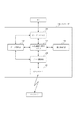
図33は、メモリリーダにおいて、主動モードのUWB無線機器を探索する場合のフローを表した図である。本フローはデジタルカメラ側で送信したい画像を選択し、UWB無線機器置き場300に置き、メモリリーダが読み取った画像データをPCに送信する場合を例に説明する。この場合は、デジタルカメラ側が主動モードになり、メモリリーダが受動モードになって走査を開始する(この走査モードのことを以後、主動モード走査と呼ぶ)。本フローでは、最初にUWB無線機器の位置を疎検出して例えば走査ポイント3001の4点の内部にあることを予測する。次にこの4点の中の予測ポイントを計算し、実際の位置を検出する。 FIG. 33 is a diagram showing a flow in the case of searching for a UWB wireless device in the main operation mode in the memory reader. This flow will be described with reference to an example in which an image to be transmitted is selected on the digital camera side, placed in the UWB wireless device storage 300, and image data read by a memory reader is transmitted to a PC. In this case, the digital camera side is in the main mode, and the memory reader is in the passive mode to start scanning (this scanning mode is hereinafter referred to as main mode scanning). In this flow, first, the position of the UWB wireless device is sparsely detected, and predicted to be within, for example, four scanning points 3001. Next, a prediction point among these four points is calculated, and an actual position is detected.
本フローはS3300から始まり、S3301に進む。この時点で、デジタルカメラ側で画像が選択され、UWB無線機器置き場300に置かれている。S3301では、カードリーダのUWBユニットを受動モードのサーチ状態にしてS3302に進む。S3302ではデジタルカメラの位置を疎検出する。このS3302の詳細は図34のフローを用いて説明する。 This flow starts from S3300 and proceeds to S3301. At this point, an image is selected on the digital camera side and placed in the UWB wireless device storage area 300. In step S3301, the UWB unit of the card reader is set to the passive mode search state, and the flow advances to step S3302. In step S3302, the position of the digital camera is sparsely detected. Details of S3302 will be described with reference to the flowchart of FIG.
図34はメモリリーダにおいて、主動モードのUWB無線機器を疎検出する場合のフローを表した図である。図34はS3400から始まり、S3401に進む。S3401では、XY駆動ユニット400は走査ポイント3001を走査順3002に従って走査する。S3402に進み、UWBユニットが検出した信号は一定値以上かどうかを判断する。一定値以上であれば、その走査ポイントの近辺にデジタルカメラが存在すると判断してS3403に進み、走査ポイント、信号レベル、主動機IDを記憶してS3404に進む。一定値以上でなければ、デジタルカメラは存在しないということなので、S3404に進む。S3404では全ての走査ポイントを走査したかどうかを判断し、全て走査したのならばS3405に進み、そうでなければS3401に戻る。S3405では、隣接する4点で信号レベルが一定値になっているエリアを検出する。具体的には図31で示されるようなエリアになる。図31はUWB無線機器の移動によるデバイス位置の疎検出を説明する図であり、3100の予測エリア1及び、3101の予測エリア2では4点において信号レベルが一定値以上になっている。全ての予測エリアを検出したら、S3406に進み、図34のフローを終了する。
FIG. 34 is a diagram illustrating a flow in the case where sparse detection is performed for UWB wireless devices in the main operation mode in the memory reader. FIG. 34 starts from S3400 and proceeds to S3401. In step S3401, the XY drive unit 400 scans the scan point 3001 according to the scan order 3002. In step S3402, it is determined whether the signal detected by the UWB unit is a certain value or more. If it is equal to or greater than a certain value, it is determined that a digital camera is present in the vicinity of the scanning point, and the process proceeds to S3403. The scanning point, signal level, and main motor ID are stored, and the process proceeds to S3404. If it is not equal to or greater than a certain value, it means that there is no digital camera, and the process advances to S3404. In step S3404, it is determined whether all scanning points have been scanned. If all scanning points have been scanned, the process proceeds to step S3405. If not, the process returns to step S3401. In S3405, an area where the signal level is a constant value at four adjacent points is detected. Specifically, the area is as shown in FIG. FIG. 31 is a diagram for explaining sparse detection of device positions due to movement of a UWB wireless device. In the prediction area 1 of 3100 and the
S3302では、以上の図34のフローを実行してからS3303に遷移する。S3303では、S3302において少なくとも一つ以上の予測エリアが検出できたかどうかを判断する。できた場合にはS3304に進み、できなかった場合にはS3308に進み、本フローを終了する。S3304からS3307では疎検出で検出された予測エリアに対して詳細検出を行う。S3304では予測エリアの4点から予測デバイス位置を検出する。具体的には図32を用いて説明する。 In S3302, after executing the above flow of FIG. 34, the process proceeds to S3303. In step S3303, it is determined whether at least one prediction area has been detected in step S3302. If YES in step S3304, if NO in step S3308, the flow ends. In steps S3304 to S3307, detailed detection is performed on the prediction area detected by the sparse detection. In step S3304, the predicted device position is detected from the four points in the predicted area. This will be specifically described with reference to FIG.
図32はデバイスの位置の詳細検出を説明する図である。 FIG. 32 is a diagram for explaining detailed detection of the position of the device.
S3302において疎検出をしたことで、図32(a)のように信号強度Aを持つ走査ポイント3201から信号強度Dを持つ走査ポイント3204までの4点での信号強度が分かる。信号の強度、すなわち電界の強度は距離の2乗または3乗に比例するため、電界の強さの平方根、または三乗根を用いて比を用いて予測デバイスまでの距離を算出することができる。したがって、上記4点の走査ポイントから予測デバイスまでの距離を算出することで予測デバイス位置3200を検出することができる。なお、2乗を用いるか、3乗を用いるかは、UWBユニットのカプラが静電界を用いるか、誘導電界を用いるかで判断すればよい。また、静電界で誘導電界無い場合でも、距離と信号強度の特性に応じて判断すれば良い。このようにしてS3304で予測デバイス位置3200を検出したら、S3305に進む。 By performing the sparse detection in S3302, the signal intensity at four points from the scanning point 3201 having the signal intensity A to the scanning point 3204 having the signal intensity D as shown in FIG. Since the signal strength, that is, the electric field strength is proportional to the square or the third power of the distance, the distance to the prediction device can be calculated using a ratio using the square root or the third root of the electric field strength. . Therefore, the predicted device position 3200 can be detected by calculating the distance from the four scanning points to the predicted device. Whether to use the square or the cube should be determined based on whether the coupler of the UWB unit uses an electrostatic field or an induced electric field. Even if there is no induced electric field due to an electrostatic field, the determination may be made according to the characteristics of distance and signal strength. When the predicted device position 3200 is detected in S3304 in this way, the process proceeds to S3305.
S3305では予測デバイス位置3200を中心とした新たな4点を設定して、さらに詳細にデバイスの位置を検出する。具体的には図32(b)を用いて説明する。予測デバイス位置3200の周囲を一定の距離だけ離して正方形上に新たな4点を設定する。なお、この正方形は図32(a)で示した正方形よりも小さな正方形を設定する。その4点で測定した信号強度を3205信号強度A’から3208信号強度D’とする。図32(a)で説明した検出方法と同様に、3205信号強度A’から3208信号強度D’を用いてデバイス位置3209を検出する。 In step S3305, four new points centered on the predicted device position 3200 are set, and the device position is detected in more detail. Specifically, this will be described with reference to FIG. Four new points are set on the square by separating the predicted device position 3200 by a certain distance. Note that this square is set smaller than the square shown in FIG. The signal intensity measured at the four points is defined as 3205 signal intensity A 'to 3208 signal intensity D'. Similar to the detection method described in FIG. 32A, the device position 3209 is detected using the 3205 signal intensity A ′ to the 3208 signal intensity D ′.
S3306ではデバイス位置3200とデジタルカメラの主動機IDを記憶してS3307に進む。S3307では、S3303で見つかった全ての予測エリアに対して詳細検出を行ったかを判断して、終わっていなかったらS3304に戻り、終わっていたらS3308に進み本フローを終了する。 In step S3306, the device position 3200 and the main motive ID of the digital camera are stored, and the process advances to step S3307. In S3307, it is determined whether or not detailed detection has been performed for all the prediction areas found in S3303. If not completed, the process returns to S3304, and if completed, the process proceeds to S3308 and this flow is terminated.
以上で説明した図33、図34のフローを実施することで、XY駆動ユニット400が、UWB無線機器置き場300に置かれているUWB無線機器を精度良く検出することができる。このため、ユーザは任意の場所にデジタルカメラを置いた場合でも精度良くPCにデータを送信することができる。また、送受信に用いるデバイスとしてはデジタルカメラ、メモリカード、携帯電話などUWBユニットを搭載している任意の機器が考えられる。 By performing the flow of FIG. 33 and FIG. 34 described above, the XY drive unit 400 can accurately detect the UWB wireless device placed in the UWB wireless device storage 300. For this reason, even when the user places the digital camera in an arbitrary place, the user can transmit data to the PC with high accuracy. In addition, as a device used for transmission / reception, any device equipped with a UWB unit such as a digital camera, a memory card, and a mobile phone can be considered.
次に、UWB無線機器置き場300に置かれたデジタルカメラに、PCに保存されたデータを送信する場合を例に説明する。この場合は、デジタルカメラ側が受動モードになっており、メモリリーダが主動モードになって走査を開始する(この走査モードのことを以後、受動モード走査と呼ぶ)。デジタルカメラなどのモバイル機器はバッテリ駆動のため、通常は図18に示すような省電力モードになっていることが多い。ここでは、送信先のデジタルカメラが省電力モードになっていても送信ができる例を示す。 Next, a case where data stored in a PC is transmitted to a digital camera placed in the UWB wireless device storage 300 will be described as an example. In this case, the digital camera side is in the passive mode, and the memory reader is in the main operation mode to start scanning (this scanning mode is hereinafter referred to as passive mode scanning). Since mobile devices such as digital cameras are battery-driven, they are usually in a power saving mode as shown in FIG. Here, an example is shown in which transmission is possible even when the digital camera of the transmission destination is in the power saving mode.
最初に、カードリーダのUWBユニットを主動モードにする。次に疎検出をするために図35のフローを実施する。図35は、メモリリーダにおいて、受動モードのUWB無線機器を疎検出する場合のフローを表した図である。図35のフローはS3500から始まり、S3501に進む。S3501ではXY駆動ユニット400は走査ポイント3001を走査順3002に従って走査する。S3502では、S3501において走査するたびに、その走査ポイントで停止する。これは省電力モードとなっているデジタルカメラがサーチ状態となることを保証するためである。つまり、前述したように省電力モードとなっているデバイスはサーチ状態でないと通信する相手となるUWBユニットを認識することができない。またこの場合、図18に示したように一定時間間隔でサーチ状態となる。したがって少なくとも図18の1801T1時間は接続要求を出し続ける必要があるために、カードリーダのUWBユニットは走査ポイント3001毎に停止させる。こうすることで、省電力モードになっているデジタルカメラも検出することができる。 First, the UWB unit of the card reader is set to the main operation mode. Next, the flow of FIG. 35 is performed in order to detect sparseness. FIG. 35 is a diagram illustrating a flow in the case where sparse detection of passive-mode UWB wireless devices is performed in the memory reader. The flow in FIG. 35 starts from S3500 and proceeds to S3501. In S3501, the XY drive unit 400 scans the scanning point 3001 according to the scanning order 3002. In S3502, every time scanning is performed in S3501, the scanning is stopped at the scanning point. This is to ensure that the digital camera in the power saving mode is in the search state. That is, as described above, the device in the power saving mode cannot recognize the UWB unit with which it communicates unless it is in the search state. In this case, as shown in FIG. 18, the search state is set at regular time intervals. Accordingly, since it is necessary to continue to issue a connection request for at least 1801T1 time in FIG. 18, the UWB unit of the card reader is stopped at every scanning point 3001. In this way, a digital camera that is in the power saving mode can also be detected.
次にS3503に進み、カードリーダのUWBユニットにより検出された信号が一定値以上かどうかを判断する。一定値以上であれば、その走査ポイントの近辺にデジタルカメラが存在するということなので、S3504に進み、そうでなければS3506に進む。S3504では、走査ポイント、信号レベル、受動機IDを記憶してS3505に進む。S3505では検出したデジタルカメラの省電力モードを一時的に解除するコマンドを送信する。これにより、後に行う詳細検出のために走査する際には、上述のS3502のように走査ポイントでT1時間以上停止する必要は無くなる。S3506以降の処理は図34と同様であり、また詳細検出を終えた後の処理は、図33のS3303と同様であるので説明を省略する。 In step S3503, it is determined whether the signal detected by the UWB unit of the card reader is equal to or greater than a predetermined value. If it is greater than or equal to a certain value, it means that there is a digital camera in the vicinity of the scanning point, so the process proceeds to S3504, and otherwise, the process proceeds to S3506. In S3504, the scanning point, signal level, and passive device ID are stored, and the process proceeds to S3505. In step S3505, a command to temporarily cancel the detected power saving mode of the digital camera is transmitted. This eliminates the need to stop at the scanning point for T1 time or more as in S3502 described above when scanning for detail detection to be performed later. The processing after S3506 is the same as that in FIG. 34, and the processing after the detailed detection is finished is the same as S3303 in FIG.
以上の処理を行うことで、受信モードにあるデジタルカメラがUWB無線機器置き場300に置かれた場合にその位置を検出することができ、またPCのデータをデジタルカメラに送信することができる。加えて、デジタルカメラが省電力モードになっている場合でもデジタルカメラの検出をすることができる。さらに、最初にデジタルカメラを検出した後、デジタルカメラの省電力モードを解除することで、次の詳細検出の際には走査ポイント毎に停止する必要が無く、効率よく詳細検出をすることができる。 By performing the above processing, when the digital camera in the reception mode is placed on the UWB wireless device storage place 300, the position can be detected, and the PC data can be transmitted to the digital camera. In addition, the digital camera can be detected even when the digital camera is in the power saving mode. Furthermore, by detecting the digital camera first and then canceling the power saving mode of the digital camera, it is not necessary to stop for each scanning point in the next detailed detection, and the detailed detection can be performed efficiently. .
次に図36では、UWB無線機器置き場300に置かれたデジタルカメラが送信をしたいのか、受信をしたいのかが不明な場合を説明する。図36は、メモリリーダにおいて、主動モードおよび主動モードのUWB無線機器を探索する場合のフローを表した図である。本フローはS3600から始まり、S3601に進む。S3601では、カードリーダのUWBユニットを主動モードでの接続要求状態、および受動モードでのサーチ状態を所定のタイミングで遷移する状態にする。なぜならば、デジタルカメラが主動モードの接続要求状態であった場合は、カードリーダが接続を確立するためには受動モードのサーチ状態にある必要があるからである。また逆にデジタルカメラが受動モードのサーチ状態(またはサーチ状態とスリープ状態を遷移する省電力モード)であった場合は、カードリーダが接続を確立するためには主動モードの接続要求状態である必要があるからである。なお、この走査モードのことを以後、混合モード走査と呼ぶ。 Next, FIG. 36 illustrates a case where it is unknown whether the digital camera placed in the UWB wireless device storage place 300 wants to transmit or receive. FIG. 36 is a diagram illustrating a flow in the case where the memory reader searches for the main mode and the UWB wireless device in the main mode. This flow starts from S3600 and proceeds to S3601. In step S3601, the UWB unit of the card reader is set to a state in which the connection request state in the main operation mode and the search state in the passive mode transition at a predetermined timing. This is because when the digital camera is in the connection request state in the main mode, the card reader needs to be in the search mode in the passive mode in order to establish a connection. Conversely, if the digital camera is in the passive mode search state (or the power saving mode that transitions between the search state and the sleep state), the card reader needs to be in the main mode connection request state in order to establish a connection. Because there is. This scanning mode is hereinafter referred to as mixed mode scanning.
次にS3602ではデジタルカメラの位置を疎検出する。図37はこのS3602における疎検出の詳細を説明する図であり、メモリリーダにおいて、主動モードおよび主動モードのUWB無線機器を疎検出する場合のフローを表した図である。 In step S3602, the position of the digital camera is sparsely detected. FIG. 37 is a diagram for explaining the details of the sparse detection in S3602, and is a diagram showing a flow when the memory reader performs sparse detection of the main mode and the UWB wireless devices in the main mode.
図37のフローは、まずS3700から始まりS3701に進む。S3701では、XY駆動ユニット400は走査ポイント3001を走査順3002に従って走査する。まず、最初の走査ポイントに到着したら、S3702に進む。S3702ではカードリーダのUWBユニットを主動モードの接続要求状態にする。S3703では、上述のS3502と同様に走査ポイントで停止して、S3704に進む。S3704およびS3705は、上述のS3503およびS3505と同等なので説明を省略する。S3706では、S3506の動作に加えて、デジタルカメラのモードが受動モードなのか、主動モードなのかを記憶する。次にS3707では、カードリーダのUWBユニットを受動モードのサーチ状態にする。S3708以降の処理は上述した処理と同等なので、説明を省略する。 The flow in FIG. 37 starts from S3700 and proceeds to S3701. In S3701, the XY drive unit 400 scans the scan point 3001 according to the scan order 3002. First, when the first scanning point is reached, the process proceeds to S3702. In step S3702, the UWB unit of the card reader is brought into a connection request state in the main operation mode. In S3703, similarly to S3502 described above, the process is stopped at the scanning point, and the process proceeds to S3704. Since S3704 and S3705 are equivalent to S3503 and S3505 described above, description thereof is omitted. In step S3706, in addition to the operation in step S3506, whether the digital camera mode is the passive mode or the main operation mode is stored. In step S3707, the UWB unit of the card reader is set to the passive mode search state. Since the processing after S3708 is equivalent to the processing described above, description thereof is omitted.
このようにS3702、S3707で主動モード、受動モードを切り替えることにより、UWB無線機器置き場300に置かれるデジタルカメラが送信をしたいのか、受信をしたいのかが不明な場合でも、デジタルカメラを検出することができる。 In this way, by switching between the main mode and the passive mode in S3702 and S3707, the digital camera can be detected even if it is unclear whether the digital camera placed in the UWB wireless device storage place 300 wants to transmit or receive. it can.
以上で説明したようにUWBユニットが平面上で移動可能な装置の別の例として、UWBユニットを搭載したMFPを示す。なお、ここではMFPの場合を示すが、印刷装置を有さないスキャナでもよい。 As described above, as another example of an apparatus in which the UWB unit can move on a plane, an MFP equipped with the UWB unit is shown. Although a case of an MFP is shown here, a scanner that does not have a printing apparatus may be used.
次に、図38はUWB機器置き場に置かれた機器を走査して探索する際に、使用するMFPの機能によって走査するモードを切り替えるフローである。切り替えるモードは、具体的には主動モード走査、受動モード走査、混合モード走査である。本フローはS3800から始まり、S3801に進む。S3801ではユーザは操作部703を用いてプリント、またはスキャン、またはオートの指示を行う。するとS3802では、使用した機能がプリントであればS3803に進み、使用した機能がスキャンであればS3804に進み、使用した機能がオートであればS3805に進む。S3803では、デジタルカメラ等のUWB機器側で印刷したい画像を選択して主動モードにしてからUWB機器置き場においてあることを想定できるので、図33で示したような主動モード走査でUWB機器を探索する。一方S3804では、読み取った原稿の画像データをデジタルカメラ等のUWB機器に転送することを想定できるので、UWB機器は受動モードであり、図35で示した受動モード走査でUWB機器を探索する。さらにS3805では、デジタルカメラ1001がどちらのモードで置かれているか不明であるので、図36で示したような混合モード走査でUWB機器を探索する。この場合、UWB機器のモードによって、MFPのプリント機能を利用するか、スキャン機能を利用するかが判断される。 Next, FIG. 38 is a flow for switching the scanning mode depending on the function of the MFP to be used when scanning and searching for a device placed in the UWB device storage area. Specifically, the mode to be switched is main mode scanning, passive mode scanning, and mixed mode scanning. This flow starts from S3800 and proceeds to S3801. In step S3801, the user uses the operation unit 703 to issue a print, scan, or auto instruction. In step S3802, if the used function is printing, the process advances to step S3803. If the used function is scan, the process advances to step S3804. If the used function is auto, the process advances to step S3805. In S3803, it can be assumed that the image is to be printed on the UWB device side such as a digital camera and set to the main operation mode, and then is in the UWB device storage place. Therefore, the UWB device is searched by main operation mode scanning as shown in FIG. . On the other hand, in S3804, since it can be assumed that the image data of the read document is transferred to a UWB device such as a digital camera, the UWB device is in the passive mode, and the UWB device is searched by the passive mode scanning shown in FIG. Further, in S3805, since it is unclear in which mode the digital camera 1001 is placed, the UWB device is searched by the mixed mode scanning as shown in FIG. In this case, whether to use the print function of the MFP or the scan function is determined according to the mode of the UWB device.
以上の図38に示すフローを実行することで、プリントの時は走査スピードが速い主動モード走査を選び、スキャン、オートの時はそれぞれの走査モードを自動的に選んでくれるので、ユーザは最適な走査を自動で使い分けることができる。 By executing the flow shown in FIG. 38, the main mode scanning with a high scanning speed is selected at the time of printing, and the respective scanning modes are automatically selected at the time of scanning and auto. Scanning can be used automatically.
<実施例3>
以下、本発明の一実施形態としての無線通信システムを説明する。実施例2ではUWBユニットが移動可能に搭載されている無線通信システムを説明したが、本実施例では特にUWBユニットが読取装置における読取センサに搭載されている場合を説明する。
<Example 3>
Hereinafter, a radio communication system as an embodiment of the present invention will be described. In the second embodiment, the wireless communication system in which the UWB unit is movably mounted has been described. In this embodiment, a case in which the UWB unit is mounted on a reading sensor in the reading apparatus will be described.
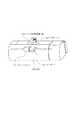
図9は、読取センサにUWBユニットを搭載したMFPを示す図である。図9(a)の読取センサ903は読取方向904の方向に水平に移動する。従ってUWB機器置き場906は、例えば図9(b)に示すような長楕円の形になる。このUWB機器置き場906は原稿蓋を閉めた上面に位置しており、この上にデジタルカメラ1001などのUWB無線機器を置くことで、前述のカードリーダの場合と同様にデータの送受信をすることができる。またこの構成では、読取センサ903の駆動部とUWBユニット902の駆動部を兼用できるため、別々の駆動部を設ける場合に比べてコストがかからないといえる。
FIG. 9 is a diagram illustrating an MFP in which a UWB unit is mounted on a reading sensor. The reading
図10は、図9で示した装置の利用方法の一例を示す図であり、次のような利用方法も考えられる。ガラス台901上に原稿1000を置き、原稿蓋905を閉めて、UWB機器置き場906にデジタルカメラ1001を置く。このようにセットした状態で、原稿の読み取りを開始する。まず多くのMFPでは原稿台に置かれた原稿の領域を検知するためにプレスキャンを行う必要があるので、読取センサ903は画像を読み取りながら読取方向904に進んでいく。このとき読取と同時に、UWBユニット902がUWB無線機器を探索しながら進んでいく。この結果デジタルカメラ1001が検出された場合は、その検出された位置を記憶する。
FIG. 10 is a diagram showing an example of a method of using the apparatus shown in FIG. 9, and the following method of use is also conceivable. The document 1000 is placed on the glass table 901, the document cover 905 is closed, and the digital camera 1001 is placed on the UWB device storage place 906. In this state, reading of the original is started. First, in many MFPs, since it is necessary to perform pre-scanning in order to detect an area of an original placed on an original table, the reading
このプレスキャンの後、再び読取センサ903が904で示した方向に走査して検知された領域の画像を読み取る。そして本構成によれば、この読み取った画像を、UWBユニット902を介してデジタルカメラ1001に転送することができる。このとき、プレスキャンの際に検出されたデジタルカメラ1001の位置にUWBユニット902を移動させればよい。例えば図10に示す位置で原稿、デジタルカメラが置かれた場合、原稿1000を読み取った後、デジタルカメラ1001の位置へUWBユニット902を移動させる。なお、図10においてデジタルカメラ1001が原稿上に置かれた場合でも、通常の読取動作では読取センサは画像を読み取ったあと図9(a)に示す所定の位置に戻る為、UWBユニット902を特別にデジタルカメラの位置に移動させる必要がない。また、UWB無線機器の探索は、プレスキャンに続く2回目の読取動作の際に行ってもよい。
After this pre-scan, the reading
またUWB無線機器の探索の結果、機器が検出された場合は、読み取った原稿の画像データを検出された機器に転送し、検出されなかった場合は例えばMFPに装着されたメモリカードに格納してもよい。そうすることでユーザは、1回の操作で原稿の読取指示に加えて、格納先の指示を行うことができる。また複数のデジタルカメラ1001が見つかった場合は、一度の操作で複数のデジタルカメラ1001に転送できるため、ユーザは何度も転送する煩わしさが無い。さらに、複数の原稿1000と複数のデジタルカメラ1001を対応する位置に配置してから読み取りを開始することで、対応する位置のデジタルカメラに対応する位置の原稿の画像データを転送することもできる。なお、この原稿の位置と転送するデジタルカメラの位置の関係は、位置関係に関する所定の条件に基づいて自動で判断させてよいし、操作キーや表示画面といったUIを用いてユーザが設定できるようにしてもよい。 If a device is detected as a result of searching for a UWB wireless device, the image data of the read document is transferred to the detected device, and if not detected, for example, stored in a memory card attached to the MFP. Also good. By doing so, the user can instruct the storage destination in addition to the document reading instruction in one operation. Further, when a plurality of digital cameras 1001 are found, the user can transfer them to the plurality of digital cameras 1001 with a single operation. Furthermore, by starting reading after arranging a plurality of documents 1000 and a plurality of digital cameras 1001 at corresponding positions, it is also possible to transfer image data of the documents at positions corresponding to the digital cameras at the corresponding positions. Note that the relationship between the position of the original and the position of the digital camera to be transferred may be automatically determined based on a predetermined condition relating to the positional relationship, or may be set by the user using a UI such as an operation key or a display screen. May be.
<実施例4>
以下、本発明の一実施形態としての無線通信システムを説明する。実施例3ではUWBユニットが読取センサに搭載されて移動可能に搭載されている無線通信システムを説明したが、本実施例ではプリントキャリッジにUWBユニットが搭載されている場合を説明する。実施例2では、プリンタ、スキャナなどが複合的に組み合わさったMFPを想定したが、実施例3ではインクジェット方式プリンタ機能のみを持ったSFP(Single Function Printer)について説明する。
<Example 4>
Hereinafter, a radio communication system as an embodiment of the present invention will be described. In the third embodiment, the wireless communication system in which the UWB unit is mounted on the reading sensor and is movably mounted has been described. In this embodiment, a case in which the UWB unit is mounted on the print carriage will be described. In the second embodiment, an MFP in which a printer, a scanner, and the like are combined is assumed. In the third embodiment, an SFP (Single Function Printer) having only an ink jet printer function will be described.
図11は、SFP1100の概略構成を示すブロック図である。SFP1100は図5で説明したMFP500から構成を加減したブロック図で説明できる。削除分は読取制御部508、読取部510、表示部511、メモリカードコントローラ516、メモリカード519、フレキシブルケーブル522である。またここではUWBユニットは、UWBユニットA1117、UWBユニットB1118の2つが設けられてある。メインボード1101とプリントキャリッジ1102はそれぞれ、これらUWBユニットB1118とUWBユニット1117を介して通信が行われる。これによりフレキシブルケーブル522は削除することができるが、詳細は後述する。また、その他のブロックの説明は図5と同等なので省略する。
FIG. 11 is a block diagram illustrating a schematic configuration of the
図12は、SFP1100の外観および内部構成の透視図である。メインボード1101がSFP筐体の右側下方に取り付けられている。プリントキャリッジ1102は記録制御部1119の制御により、シャフトに従って水平方向に移動する。このプリントキャリッジ1102は、不図示のエンコーダを読み取ることでシャフトのどの位置にいるかを知ることができる。このように水平方向に移動しながら、プリントヘッド制御部1113がインクの吐出制御を行い、プリントヘッド1114がインクを用紙に吐出することで用紙上に画像を形成する。
FIG. 12 is a perspective view of the external appearance and internal configuration of the
UWBユニットB1118はUWB無線機器置き場1205に近接されたデジタルカメラ1206などのUWB無線機器から画像データを受信する。UWBユニットB1118は受信した画像データをメインボード1101に送信して、メインボード1101では各種の画像処理や、また画像データからプリントデータへの変換が行われる。その後、再びUWBユニットB1118を用いて、メインボード1101で得られたプリントデータをUWBユニットA1117に送信する。するとUWBユニットA1117が受信したプリントデータに基づき、プリントヘッド制御部1113がプリントヘッド1114にインクの吐出をさせることで、印刷を行うことができる。なお、UWBユニット間の通信のタイミングはプリントキャリッジ1102がUWBユニットB1118に近接したときであり、図12においてはプリントキャリッジ1102が右端付近に移動したときである。このようにプリントキャリッジ1102が右端にきたときの場所をホームポジションと定める。このホームポジションの位置には図示していないがプリントヘッドの回復ユニットがあり、インクの目詰まりを防止する定期吐出に使うインクの吸収体や、乾燥防止用のキャップなどで構成されている。 The UWB unit B 1118 receives image data from a UWB wireless device such as a digital camera 1206 in the vicinity of the UWB wireless device storage 1205. The UWB unit B 1118 transmits the received image data to the main board 1101, and the main board 1101 performs various image processing and conversion from image data to print data. Thereafter, the print data obtained on the main board 1101 is transmitted to the UWB unit A 1117 again using the UWB unit B 1118. Then, based on the print data received by the UWB unit A 1117, the print head control unit 1113 can cause the print head 1114 to discharge ink to perform printing. Note that the communication timing between the UWB units is when the print carriage 1102 approaches the UWB unit B 1118, and in FIG. 12, the print carriage 1102 moves near the right end. In this way, the position when the print carriage 1102 comes to the right end is determined as the home position. Although not shown, there is a print head recovery unit at the home position, which includes an ink absorber used for regular ejection to prevent clogging of ink, a cap for preventing drying, and the like.
図12で示すように、メインボード1101とプリントキャリッジ1102を、近接無線通信を行うことができるUWBユニットで無線接続することで印刷が可能であるので、フレキシブルケーブルが不要となる。しかも近接無線通信であるため、複数のSFPが近くにある場合でも複雑な通信プロトコルを必要としないため、スループットを挙げることができるので、プリントキャリッジの速度を早くできるという効果も有する。 As shown in FIG. 12, printing can be performed by wirelessly connecting the main board 1101 and the print carriage 1102 with a UWB unit capable of performing close proximity wireless communication, so that a flexible cable is not necessary. In addition, since close proximity wireless communication is used, a complicated communication protocol is not required even when a plurality of SFPs are close to each other. Therefore, throughput can be increased, and the print carriage speed can be increased.
図28は図11、図12で説明したSFPがデジタルカメラからの画像データの印刷を行う処理を説明するシーケンス図である。 FIG. 28 is a sequence diagram illustrating a process in which the SFP described in FIGS. 11 and 12 prints image data from a digital camera.
最初にデジタルカメラ側で、ユーザが印刷する画像を選択して画像を送信する操作をしてから、デジタルカメラをUWB無線機器置き場1205に置く。この時点で、デジタルカメラは主動モードとなっており、またSFPは受動モードとなっている。すると2800接続確立によって、デジタルカメラとUWBユニットBとの接続が確立される。この接続確立において、デジタルカメラはUWBユニットBの受動機IDを記憶し、UWBユニットBはデジタルカメラの主動機IDを記憶する。次にSFPは2801でプリントキャリッジ1102をホームポジションに移動させて、UWBユニットAとUWBユニットBが通信できる状態にしておく。次に、2802では、UWBユニットAとUWBユニットBの接続を確立する。このときUWBユニットBは、UWBユニットAの主動機IDをデジタルカメラの主動機IDとは別の領域に保存する。これによってUWBユニットBは、デジタルカメラと通信するか、UWBユニットAと通信するかを、選択的に切り替えることができる。ただしこの場合、同時に両方と通信することはできない。 First, after the user selects an image to be printed and transmits an image on the digital camera side, the digital camera is placed in the UWB wireless device storage area 1205. At this point, the digital camera is in the main operation mode and the SFP is in the passive mode. Then, the connection between the digital camera and the UWB unit B is established by establishing the 2800 connection. In this connection establishment, the digital camera stores the passive machine ID of the UWB unit B, and the UWB unit B stores the main motor ID of the digital camera. Next, at 2801, the SFP moves the print carriage 1102 to the home position so that the UWB unit A and the UWB unit B can communicate with each other. Next, in 2802, a connection between UWB unit A and UWB unit B is established. At this time, the UWB unit B stores the main motor ID of the UWB unit A in a different area from the main motor ID of the digital camera. As a result, the UWB unit B can selectively switch between communicating with the digital camera and communicating with the UWB unit A. In this case, however, it is not possible to communicate with both at the same time.
2803では、UWBユニットBはデジタルカメラとの接続に切り替える。2804では画像データ要求信号をデジタルカメラに対して送信する。2805で、デジタルカメラはユーザ操作によって選択された画像の画像データの転送を開始する。2805、2806等のように一枚の画像データは複数のパケットに分割されて送信される。2807において、UWBユニットBが所定のサイズの画像データを受信したら、データ変換部1107により画像データをプリントデータに変換してから、UWBユニットAに送信する準備を行う。2808では、UWBユニットBはデジタルカメラとの接続を一時的に中断して、UWBユニットAとの接続状態にする。
In 2803, the UWB unit B switches to connection with a digital camera. In 2804, an image data request signal is transmitted to the digital camera. In 2805, the digital camera starts transferring image data of the image selected by the user operation. One image data such as 2805 and 2806 is divided into a plurality of packets and transmitted. In
不図示のエンコーダからの情報により、プリントキャリッジ1102がホームポジションに接近することがわかると、2809、2810においてプリントデータをUWBユニットBからUWBユニットAに対して送信する。このように複数回でプリントデータを送信して、UWBユニットAが所定量のプリントデータを受信したらプリントキャリッジは印刷を開始する。2811の印刷中は、プリントキャリッジ1102はシャフト上を往復動作するために、UWBユニットAとUWBユニットBは通信することができない。2812で、UWBユニットBはデジタルカメラとの接続状態にして、2813ではデジタルカメラに対して、画像データの続きを送出するように要求する。2814から2816ではデジタルカメラからUWBユニットBに対して続きのデータを送出する。なおデータを送出する時間は、2811でプリントキャリッジが往復のために用いる時間とすると効率が良い。 When it is found from the information from the encoder (not shown) that the print carriage 1102 approaches the home position, print data is transmitted from the UWB unit B to the UWB unit A in 2809 and 2810. As described above, when the print data is transmitted a plurality of times and the UWB unit A receives a predetermined amount of print data, the print carriage starts printing. During printing of 2811, the print carriage 1102 reciprocates on the shaft, so the UWB unit A and the UWB unit B cannot communicate. In 2812, the UWB unit B is connected to the digital camera, and in 2813, the digital camera is requested to send the continuation of the image data. In steps 2814 to 2816, subsequent data is transmitted from the digital camera to the UWB unit B. Note that the time for sending data is 2811, which is efficient when the print carriage uses it for reciprocation.
2817では2807と同様に、UWBユニットBが受信した画像データをプリントデータに変換してから、UWBユニットAに送信する準備を行う。プリントキャリッジは2811での印刷が終わったらプリントキャリッジをホームポジションに移動しておく。2818でUWBユニットBはUWBユニットAとの接続状態にする。2820でUWBユニットBはUWBユニットAに対してプリントデータを転送する。この後は、印刷が終わるまで2809から2818までのシーケンスを繰り返すことで印刷をすることができる。 In 2817, as in 2807, the image data received by the UWB unit B is converted into print data, and preparations for transmission to the UWB unit A are made. The print carriage moves to the home position after the printing at 2811 is completed. In 2818, UWB unit B is connected to UWB unit A. At 2820, UWB unit B transfers print data to UWB unit A. Thereafter, printing can be performed by repeating the sequence from 2809 to 2818 until printing is completed.
以上の図12の構成、及び図28に示すフローを実施することで、SFPはデジタルカメラからのデータを無線で受信することができる。また、メインボードとプリントキャリッジの間を無線で送受信できるので、フレキシブルケーブルが不要となる。加えて、近接無線で送受信するため、周囲の無線機器の影響を受けることが無いので、シンプルなプロトコルで通信でき、スループットを改善できる。さらに、UWBユニットBはデジタルカメラからの受信と、プリントキャリッジへの送信を兼ねているため、装置のコストダウンにもつながる。 By implementing the configuration shown in FIG. 12 and the flow shown in FIG. 28, the SFP can wirelessly receive data from the digital camera. In addition, since the main board and the print carriage can be transmitted and received wirelessly, a flexible cable is not necessary. In addition, since transmission / reception is performed by close proximity wireless communication, there is no influence of surrounding wireless devices, so communication can be performed with a simple protocol and throughput can be improved. Furthermore, since the UWB unit B serves as both reception from the digital camera and transmission to the print carriage, the cost of the apparatus is also reduced.
次に、SFPのプリントキャリッジにUWBユニットを備えている構成の別の一例を示す。図13はプリントキャリッジ1102とメインボード1101とUWBユニット1303が一体型になったSFPを示す図である。この図のSFPのプリント中には、メインボード1101及びUWBユニット1303は、プリントキャリッジ1102とともにシャフトに沿って水平方向に移動する。したがってUWBユニット1303がUWB無線機器置き場1304の下を通過する際に、デジタルカメラとUWBユニットはデータを送受信することができる。図13の例では、UWB無線機器置き場1304はプリントキャリッジの移動する範囲の中央に配置されている。これは、印刷用紙の給紙が中央基準になっているため、プリントキャリッジ1102は中央付近を往復する確率が高いためである。UWB無線機器置き場1304の位置は、装置の給紙機構や、回復ユニットの位置を考慮した位置に配置するのが好ましい。 Next, another example of a configuration in which a UWB unit is provided in an SFP print carriage will be described. FIG. 13 is a diagram showing an SFP in which a print carriage 1102, a main board 1101, and a UWB unit 1303 are integrated. During the printing of the SFP in this figure, the main board 1101 and the UWB unit 1303 move along the shaft along with the print carriage 1102 in the horizontal direction. Therefore, when the UWB unit 1303 passes under the UWB wireless device storage 1304, the digital camera and the UWB unit can transmit and receive data. In the example of FIG. 13, the UWB wireless device storage 1304 is arranged at the center of the range in which the print carriage moves. This is because the print carriage 1102 has a high probability of reciprocating near the center because the printing paper is fed in the center. The position of the UWB wireless device storage 1304 is preferably arranged in consideration of the paper feeding mechanism of the apparatus and the position of the recovery unit.
なお図13の構成は、図11のブロックを改変した構成で実現できる。具体的にはUWBユニットA1117を削除し、メインボード1101とプリントキャリッジ1102を一体にしてバスケーブルで接続した構成となる。 The configuration in FIG. 13 can be realized by modifying the block in FIG. Specifically, the UWB unit A 1117 is deleted, and the main board 1101 and the print carriage 1102 are integrated and connected by a bus cable.
図29は図13で説明したSFPがデジタルカメラからの画像データの印刷を行う処理を説明するシーケンス図である。 FIG. 29 is a sequence diagram illustrating a process in which the SFP described with reference to FIG. 13 prints image data from a digital camera.
最初にデジタルカメラ側で、ユーザが印刷する画像を選択して画像を送信する操作をしてから、デジタルカメラをUWB無線機器置き場1304に置く。この時点で、デジタルカメラは主動モードとなっており、またSFPは受動モードとなっている。 First, after the user selects an image to be printed and transmits an image on the digital camera side, the digital camera is placed in the UWB wireless device storage 1304. At this point, the digital camera is in the main operation mode and the SFP is in the passive mode.
まず2900でプリントキャリッジ1102はホームポジションに移動する。ここでいうホームポジションとは、UWB無線機器置き場1304の下で、デジタルカメラとUWBユニットが通信可能な位置を指す。2900でホームポジションに移動するトリガは、ユーザがプリンタ側で印刷開始のトリガを与えてもよいし、プリントキャリッジ1102のデフォルトの位置をホームポジションにしても良い。2901の接続確立によって、デジタルカメラとUWBユニットとの接続が確立される。デジタルカメラはUWBユニットの受動機IDを記憶し、またUWBユニットBはデジタルカメラの主動機IDを記憶する。
First, at 2900, the print carriage 1102 moves to the home position. The home position here refers to a position where the digital camera and the UWB unit can communicate with each other under the UWB wireless device storage 1304. As a trigger for moving to the home position in 2900, the user may give a print start trigger on the printer side, or the default position of the print carriage 1102 may be the home position. By establishing the
2902では画像データ要求信号をデジタルカメラに対して送信する。2903で、デジタルカメラはユーザ操作によって選択された画像の画像データの転送を開始する。2903、2904等のように一枚の画像データは複数のパケットに分割されて送信される。このように所定のサイズの画像データがUWBユニットにより受信されたら、プリントキャリッジは印刷を開始する。2905では、メインボード1101により得られたプリントデータに基づきプリントヘッド1114がインクを吐出して印刷を行う。このプリントデータの生成方法は図28と同様であり、詳細な説明は省略する。プリントキャリッジ1102はシャフト上を往復動作するために、移動中はデジタルカメラとUWBユニットは通信することができない。2906で、プリントキャリッジは受信した画像データを全て印刷し終わったら、ホームポジションに移動する。または、プリントキャリッジが印刷中にホームポジションを通過したら2906に遷移しても良い。2907以降は印刷が終わるまで2902からのシーケンスを繰り返すことになるので説明は省略する。 In 2902, an image data request signal is transmitted to the digital camera. In 2903, the digital camera starts transferring the image data of the image selected by the user operation. One image data such as 2903 and 2904 is divided into a plurality of packets and transmitted. When image data of a predetermined size is received by the UWB unit in this way, the print carriage starts printing. In 2905, the print head 1114 performs printing by ejecting ink based on the print data obtained by the main board 1101. The print data generation method is the same as that shown in FIG. 28, and a detailed description thereof will be omitted. Since the print carriage 1102 reciprocates on the shaft, the digital camera and the UWB unit cannot communicate during movement. In 2906, when all the received image data has been printed, the print carriage moves to the home position. Alternatively, when the print carriage passes the home position during printing, the process may transit to 2906. From 2907 onward, the sequence from 2902 will be repeated until printing is completed, and the description thereof will be omitted.
図13で示すように、プリントキャリッジ1102とメインボード1101とUWBユニット1303を一体型に配置することで、図12におけるUWBユニットBを削除することができ、さらにコストダウンすることができる。また、UWB無線機器置き場1304はプリントキャリッジが往復する際に、印刷の基準点に配置されることで、データの送受信の効率を上げることができる。 As shown in FIG. 13, by arranging the print carriage 1102, the main board 1101, and the UWB unit 1303 as a single unit, the UWB unit B in FIG. 12 can be deleted, and the cost can be further reduced. Further, the UWB wireless device storage 1304 can be arranged at a printing reference point when the print carriage reciprocates, thereby improving the efficiency of data transmission / reception.
<実施例5>
以下、本発明の一実施形態としての無線通信システムを説明する。以上の実施例で説明した無線通信システムでは、UWBユニットが搭載された装置のユーザによる指示は、例えばキーなどの操作部への操作で行われる場合を想定して説明したが、本発明はそれに限るものではない。本実施例ではユーザの指示をナビシートにより行う場合を説明する。
<Example 5>
Hereinafter, a radio communication system as an embodiment of the present invention will be described. In the wireless communication system described in the above embodiment, the description has been given assuming that the instruction by the user of the device equipped with the UWB unit is performed by operating the operation unit such as a key. It is not limited. In this embodiment, a case where a user's instruction is given by a navigation sheet will be described.
図16は、ユーザがUWB無線通信に関する指示をするためのナビシートを示す図である。ナビシートとは、ユーザがMFPに対して操作の指示をするためのシートであり、例えば図のナビシート1600はマークシート方式のシートである。ユーザは所望の箇所にマークして、MFPはこのマークされたシートを読み取ってマークされた箇所を判別することで、ユーザの指示を入力することができる。特にこの図のようにマークシート方式の場合、一覧性よく操作指示できる。 FIG. 16 is a diagram showing a navigation sheet for a user to give an instruction regarding UWB wireless communication. The navigation sheet is a sheet for the user to give an operation instruction to the MFP. For example, the navigation sheet 1600 in the figure is a mark sheet type sheet. The user marks a desired location, and the MFP can input the user's instruction by reading the marked sheet and determining the marked location. In particular, in the case of the mark sheet system as shown in this figure, it is possible to instruct operation with good listability.
次に、ユーザがこのナビシートを使用した場合のUWB無線通信の一例を説明する。最初に、UWB機器置き場に少なくとも一つ以上のUWB無線機器を置く。次にUWBユニットが置かれたUWB無線機器をすべて検出する。なお検出する際には、各UWB無線機器内のデータの一覧も取得する。 Next, an example of UWB wireless communication when the user uses this navigation sheet will be described. First, at least one UWB wireless device is placed in the UWB device storage area. Next, all UWB wireless devices in which the UWB unit is placed are detected. At the time of detection, a list of data in each UWB wireless device is also acquired.
次に、図16で示したナビシート1600を印刷する。図の1601は検出されたデバイスの一覧を印刷するエリアである。今回の例では、カメラA、カメラB、携帯電話Aが検出されている。1602、1603は実行する機能を選択する欄であり、データ転送を指示するために1602を選択した場合には、送信する側のデバイス1604と受信する側のデバイス1605を選択する。印刷を指示するために1603を選択した場合には、MFPの印刷部で印刷させたい画像データを有するデバイス1606を選択する。1607から1609までは、検出されたデバイスの内部のデータ一覧をあらわしている。1602を選んだ場合は、送信するデバイスの中から送信するデータを選択する。1603を選んだ場合は、印刷するデバイスの中から印刷するデータを選択する。ユーザはすべて記入が済んだら、ナビシート1600をMFPの原稿台に置き、原稿を読み取る。原稿を読み取ったMFPは、ナビシートにより指示された処理を実行する。
Next, the navigation sheet 1600 shown in FIG. 16 is printed.
<実施例6>
以下、本発明の一実施形態としての無線通信システムを説明する。以上の実施例では、高速であり、近距離で行うUWB方式の近接無線通信について説明した。本実施例ではこの近接無線通信の他に、この近接無線通信と比較して低速であるが、長距離で通信可能な無線通信を利用する場合を説明する。例えば次のようなケースがある。
<Example 6>
Hereinafter, a radio communication system as an embodiment of the present invention will be described. In the above embodiment, the UWB close proximity wireless communication performed at a high speed and at a short distance has been described. In this embodiment, in addition to this proximity wireless communication, a case will be described in which wireless communication that is slower than this proximity wireless communication but can communicate over a long distance is used. For example, there are the following cases.
最初に、デジタルカメラをユーザが操作して、UWB方式の近接無線通信を用いてデジタル画像を送信するための状態に遷移させる。次にMFPが、デジタルカメラから近接無線通信により画像データを受信して印刷する。 First, the user operates the digital camera to change to a state for transmitting a digital image using UWB close proximity wireless communication. Next, the MFP receives and prints image data from the digital camera by proximity wireless communication.
このように印刷をしている間は、デジタルカメラは印刷の状況をMFPから受信して表示部に表示し、またユーザからの追加指示がある場合はその指示をMFPに送信する。このような通信では、例えばMFPに搭載されたUWBユニットが印刷中に移動する場合には、近距離の通信が行えないことがある。したがって、このような印刷の状況の送受信、およびユーザからの追加指示の送受信には、UWB方式のような近距離で高速な通信が可能な近接無線通信ではなく、低速であるが長距離で通信可能な長距離無線通信方式を用いられる。このような通信方式として、例えばBlueTooth(商標登録)などが例に挙げられる。 During printing, the digital camera receives the printing status from the MFP and displays it on the display unit. If there is an additional instruction from the user, the digital camera transmits the instruction to the MFP. In such communication, for example, when a UWB unit mounted on an MFP moves during printing, short-distance communication may not be performed. Therefore, for such transmission / reception of the printing status and transmission / reception of an additional instruction from the user, communication is performed at a low speed but a long distance instead of the proximity wireless communication capable of high-speed communication at a short distance as in the UWB system. Possible long-range wireless communication systems are used. An example of such a communication method is BlueTooth (trademark registration).
図39はUWB無線通信からBlueTooth通信へ切り替える処理を示すフローである。なお、このフローに入る以前はBlueTooth通信に設定されており、MFPは印刷の状況をデジタルカメラに送信して、デジタルカメラからの指示を受けた場合はそれを実行している。またMFPは同時に新たなデジタルカメラからの接続要求が無いかを監視している。この状況で、ユーザがデジタルカメラを操作し、印刷する画像を選択して画像を送信ためのモードに設定してから、デジタルカメラをUWB無線機器置き場に置く。 FIG. 39 is a flowchart showing processing for switching from UWB wireless communication to BlueTooth communication. Before entering this flow, it is set to BlueTooth communication, and the MFP transmits the printing status to the digital camera and executes it when receiving an instruction from the digital camera. At the same time, the MFP monitors whether there is a connection request from a new digital camera. In this situation, the user operates the digital camera, selects an image to be printed and sets a mode for transmitting the image, and then places the digital camera in the UWB wireless device storage area.
S3901では図15で示したデジタルカメラ1500と図5で示したMFP500とのUWB接続を確立してS3902に進む。S3902では、UWBユニットを用いて画像データをデジタルカメラ1500からMFP500に送信する。画像データの転送が終わり、MFPが印刷動作に入るとS3903に進んでUWB無線通信の接続を切断する。次に、MFP500のBlueTooth通信部513と、デジタルカメラ1500のBlueTooth通信部1506を用いて通信を確立する。S3905に進み、BlueToothを用いてMFP500の印刷のステータスを送受信したり、ユーザからの追加指示がある場合はその指示をMFPに送信したりする。
In S3901, a UWB connection is established between the digital camera 1500 shown in FIG. 15 and the
本実施例では、高速通信が必要な場合はUWB方式の近接高速通信を用い、比較的低速通信で良いステータスの送受信などはBlueToothを用いる。これにより、ユーザは画像通信が終わった後からはすぐに次の操作を行うことができ、機器の使用効率が高まるという効果が得られる。 In this embodiment, when high-speed communication is required, UWB proximity high-speed communication is used, and bluetooth is used for status transmission and reception that is relatively low-speed communication. As a result, the user can perform the next operation immediately after the image communication is completed, and an effect of increasing the use efficiency of the device can be obtained.
<実施例7>
以下、本発明の一実施形態としての無線通信システムを説明する。本システムは前述のMFP500、及び、SFP1100に関するものであり、以上の実施例でも説明したUWB無線機器置き場に関する実施例である。
<Example 7>
Hereinafter, a radio communication system as an embodiment of the present invention will be described. This system relates to the
図8は可動式操作部を示す図である。MFP500において、操作部703の形状を図8(A)に示すような可動式操作部800のようにする。この可動式操作部800を図8(B)のように可動させると、下面にはUWB無線機器置き場801が現れる構成になっている。また可動式操作部800は、閉じている間はUWBユニットの電界が届かない距離になるようになっている。つまり、可動式操作部800の厚みは電界有効閾値よりも大きい値になっており、可動式操作部800はMFPの壁面までにはUWBユニットの電界が届かない距離に配置されている。
FIG. 8 is a diagram showing the movable operation unit. In the
この図8に示すような開閉式の構成にすることで、UWB無線通信機器が不意に近接されたために、ユーザが意図しない通信が開始されてしまうことを防ぐことができる。例えば、ユーザがデジタルカメラを主動モードにしていた場合、デジタルカメラを携帯したままMFPを操作している最中に誤って通信が確立されてしまい、意図しない画像を印刷してしまうことを防ぐことができる。 By adopting the open / close-type configuration as shown in FIG. 8, it is possible to prevent the communication unintended by the user from being started because the UWB wireless communication device is inadvertently approached. For example, if the user has set the digital camera to the main mode, it prevents the communication from being accidentally established while operating the MFP while carrying the digital camera and printing an unintended image. Can do.
また図8の可動式操作部800が(A)に示すような状態の時にはUWBユニットの電界を遮断して送受信できない状態にし、(B)に示すような状態の時にはUWBユニットの電界を送受信できる状態にするように制御しても良い。このような制御をすることで、意図しない画像を印刷してしまう可能性を更に低くすることができる。また、消費電力を低く抑えることもできる。 Further, when the movable operation unit 800 in FIG. 8 is in the state as shown in FIG. 8A, the electric field of the UWB unit is cut off so that transmission / reception cannot be performed, and in the state as shown in FIG. You may control so that it may be in a state. By performing such control, it is possible to further reduce the possibility of printing an unintended image. In addition, power consumption can be kept low.
また図13に示すSFPでは、UWB無線機器置き場1304にデジタルカメラを置いてから印刷する構成になっている。このとき、プリントキャリッジ1102が水平方向に往復移動を繰り返しながら印刷を行うので、SFPの筐体に振動が生じる。また、印刷用紙を給紙、搬送及び排紙する動作においても筐体に振動が生じる。 Further, the SFP shown in FIG. 13 is configured to print after placing a digital camera in the UWB wireless device storage 1304. At this time, since the print carriage 1102 performs printing while repeating reciprocating movement in the horizontal direction, vibration is generated in the SFP casing. In addition, the housing is also vibrated during operations of feeding, transporting, and discharging printing paper.
そこで図14に、UWB無線機器置き場の形状の例を表す。UWB無線機器置き場1304を図14(A)UWB無線機器置き場1に示すような形状にする。このようにUWB無線機器置き場に窪みを持たせることで、前記の筐体の振動が発生した場合でも、デジタルカメラなどのUWB無線機器が転落してしまうことを防ぐことができる。なお、この窪みは転落を防げるだけの深度を持つ。また、図14(B)UWB無線機器置き場2に示すように、摩擦係数の大きい部材を窪みに接着等で設けても良い。このような構成により、転落防止の効果を向上させることができる。
FIG. 14 shows an example of the shape of the UWB wireless device storage area. The UWB wireless device storage 1304 is shaped as shown in FIG. 14 (A) UWB wireless device storage 1. By providing a depression in the UWB wireless device storage place in this way, it is possible to prevent a UWB wireless device such as a digital camera from falling even when the casing is vibrated. In addition, this dent has a depth enough to prevent falling. Further, as shown in FIG. 14 (B) UWB wireless
また、図14(C)UWB無線機器置き場3に示すように、プリントキャリッジ1102の特性を考慮して片側に傾斜した形状にしても良い。プリントキャリッジ1102は制御の方式によって往復動作のうち、往路の方が速度が速いため、振動によるデジタルカメラの移動は一方向に偏ってしまう。したがって図14(C)のような構成にして、移動が予測される側に傾斜を傾けておけば、デジタルカメラが転落する可能性を低くすることができる。また、UWB無線機器は対象の機器の大きさが限定されていない場合、図14(A)の構成では、窪みに収まらない可能性があるが、図14(C)では任意の大きさの機器でも対応できる。また、図14(D)に示すように、鋭角方のつけて振動によって移動した場合は一箇所に集まるようにしても良い。集まる場所は、UWBユニットの信号が最も強く送受信できる場所に設定する。そうすることで、ユーザが多少ずれた場所にデジタルカメラをセットしても、振動によって最適な場所に戻る可能性がある。 Further, as shown in FIG. 14C, the UWB wireless device storage 3 may have a shape inclined to one side in consideration of the characteristics of the print carriage 1102. Since the print carriage 1102 has a higher speed in the forward path among reciprocating operations depending on the control method, the movement of the digital camera due to vibration is biased in one direction. Therefore, if the configuration shown in FIG. 14C is used and the inclination is inclined to the side where movement is predicted, the possibility of the digital camera falling can be reduced. Further, in the case where the size of the target device is not limited, the UWB wireless device may not fit in the recess in the configuration of FIG. 14A, but in FIG. 14C, the device of an arbitrary size But you can. Further, as shown in FIG. 14D, when moving by vibration with an acute angle, they may be gathered in one place. The gathering place is set to a place where the UWB unit signal can be transmitted and received most strongly. By doing so, even if the user sets the digital camera in a slightly deviated place, there is a possibility of returning to the optimum place by vibration.
本発明は、無線通信装置及び無線通信システムで、特に近接無線通信が可能な装置と、それらの機器間で確立する一対一の接続の確立およびそれらの無線通信システムに利用可能である。 INDUSTRIAL APPLICABILITY The present invention is applicable to a wireless communication device and a wireless communication system, particularly a device capable of close proximity wireless communication, establishment of a one-to-one connection established between these devices, and those wireless communication systems.
100 UWBユニット
101 通信モジュール
102 カプラ
103 RF部
104 送受信制御部
105 EEPROM
200 メモリリーダ
201 UWBユニット
202 CPU
203 駆動制御部
204 データ蓄積部
205 データ変換部
206 ホストデバイスI/F
400 XY駆動ユニット
401 Xシャフト
402 Yシャフト
500 MFP
501 メインボード
502 プリントキャリッジ
503 CPU
504 ROM
505 RAM
506 画像メモリ
507 データ変換部
508 読取制御部
509 操作部
510 読取部
511 表示部
512 符号復号化処理部
513 BlueTooth通信部
514 データ蓄積部
515 給紙部
516 メモリカードコントローラ
517 プリントヘッド制御部
518 プリントヘッド
519 メモリカード
520 デジタルカメラ
521 システムバス
522 フレキシブルケーブル
523 バスケーブル
524 UWBユニット
700 インタフェースパネル
702 UWB無線機器置き場
703 操作部、704
800 可動式操作部
1500 デジタルカメラ
1501 CPU
1502 ROM
1503 RAM
1504 画像メモリ
1505 データ変換部
1506 BlueTooth通信部
1507 操作部
1508 表示部
1509 撮像部
1510 メモリカードコントローラ
1511 UWBユニット
1512 メモリカード
1513 プリンタ
1514 システムバス
100 UWB unit 101
200
203
400 XY drive unit 401 X shaft 402
501 Main board 502 Print carriage 503 CPU
504 ROM
505 RAM
506
800 Movable operation unit 1500 Digital camera 1501 CPU
1502 ROM
1503 RAM
1504 Image memory 1505 Data conversion unit 1506
Claims (7)
前記無線通信ネットワークを介して前記第1の無線通信装置とデータを無線通信する第2の無線通信装置と、
を含む無線通信システムにおいて、
前記第1の無線通信装置は、
当該第1の無線通信装置に前記無線通信の中断要因が発生したときに、当該中断要因の種類に応じて、前記第2の無線通信装置との無線通信を中断させるための中断信号として中断要因の第1の種類に対応する第1の信号または当該無線通信を中断させ当該無線通信を再開させるときの再開条件を指定するための中断信号として中断要因の第2の種類に対応する第2の信号を当該第2の無線通信装置に送信する送信手段と、
当該第1の無線通信装置の前記中断要因が解除されたときに、当該中断要因の解除を前記第2の無線通信装置に通知する通知手段と、を有し、
前記第2の無線通信装置は、
前記第1の無線通信装置とデータを無線通信する通信部と、
前記送信手段により前記第1の無線通信装置から前記中断信号が送信された場合、前記通信部による前記第1の無線通信装置との無線通信を中断して前記通信部による前記第1の無線通信装置からの通知を受信可能な状態で待機する前記第1の信号に対応する第1の休止モードと、当該通信部の電源を遮断する前記第2の信号に対応する第2の休止モードとのうちの、当該送信された中断信号に対応する中断要因の種類に応じた休止モードで待機するように、当該通信部を制御する制御手段と、
前記制御手段により前記通信部が前記第1の休止モードで待機している場合に前記第1の無線通信装置の前記通知手段により中断要因の解除が通知されたことを前記第1の信号に対応する第1の再開条件として、当該第1の再開条件が満たされたときに、当該通信部により前記第1の無線通信装置に無線通信の再開を要求する第1の要求手段と、
前記制御手段により前記通信部が前記第2の休止モードで待機している場合に前記通信部の電源を遮断してから所定時間が経過したことを前記第2の信号により指定される第2の再開条件として、当該第2の再開条件が満たされたときに、当該通信部を起動して、当該通信部により前記第1の無線通信装置に無線通信の再開を要求する第2の要求手段と、
を有することを特徴とする無線通信システム。 A first wireless communication device for wirelessly communicating data via a wireless communication network;
A second wireless communication device for wirelessly communicating data with the first wireless communication device via the wireless communication network;
In a wireless communication system including:
The first wireless communication device is:
When the wireless communication interruption factor occurs in the first wireless communication device, the interruption factor is used as an interruption signal for interrupting wireless communication with the second wireless communication device according to the type of the interruption factor. The second signal corresponding to the second type of the interruption factor as the first signal corresponding to the first type of the interruption or the interruption signal for designating the resumption condition when the wireless communication is suspended and the wireless communication is resumed . Transmitting means for transmitting a signal to the second wireless communication device;
Notification means for notifying the second wireless communication device of the cancellation of the interruption factor when the interruption factor of the first wireless communication device is released;
The second wireless communication device is:
A communication unit for wirelessly communicating data with the first wireless communication device;
When the interruption signal is transmitted from the first wireless communication device by the transmission unit, the communication unit interrupts wireless communication with the first wireless communication device, and the communication unit performs the first wireless communication. A first sleep mode corresponding to the first signal that waits in a state where a notification from the apparatus can be received, and a second sleep mode corresponding to the second signal that shuts off the power supply of the communication unit. Control means for controlling the communication unit to wait in a sleep mode according to the type of interruption factor corresponding to the transmitted interruption signal,
Corresponding to the first signal that the canceling factor is notified by the notifying unit of the first wireless communication apparatus when the communication unit is waiting in the first sleep mode by the control unit. First requesting means for requesting the first wireless communication device to resume wireless communication by the communication unit when the first restarting condition is satisfied,
The second of the communication unit by the control unit is designated more that a predetermined time and then cut the power supply of the communication unit when waiting in the second sleep mode has elapsed the second signal Second request means for activating the communication unit and requesting the first wireless communication apparatus to resume wireless communication when the second restart condition is satisfied When,
A wireless communication system comprising:
前記第2の無線通信装置の第2の要求手段は、前記第1の無線通信装置から送信された前記所定時間が前記通信部の電源を遮断してから経過したときに、前記第1の無線通信装置に無線通信の再開を要求することを特徴とする請求項1または2に記載の無線通信システム。 The transmission means of the first wireless communication device notifies the second wireless communication device of the predetermined time when transmitting the second signal,
The second request means of the second wireless communication device is configured to receive the first wireless communication when the predetermined time transmitted from the first wireless communication device has elapsed since the power of the communication unit has been shut off. The wireless communication system according to claim 1, wherein the communication device is requested to resume wireless communication.
当該無線通信装置に前記無線通信の中断要因が発生したときに、当該中断要因の種類に応じて、前記通信相手との無線通信を中断させるための中断信号として、中断要因の第1の種類に対応する第1の信号または当該無線通信を中断させ当該無線通信を再開させるときの再開条件を指定するための中断信号として中断要因の第2の種類に対応する第2の信号を当該通信装置に送信する送信手段と、
当該無線通信装置の前記中断要因が解除されたときに、当該中断要因の解除を前記第2の無線通信装置に通知する通知手段と、
前記第1の信号に対応する第1の再開条件と前記第2の信号により指定される第2の再開条件のうち、前記送信手段により送信された中断信号の種類に対応する再開条件が前記通知手段による通知に基づいて満たされたときに、前記無線通信が再開されるように当該無線通信装置を制御する制御手段と、
を有することを特徴とする無線通信装置。 A wireless communication device that wirelessly communicates data with a communication partner via a wireless communication network,
When a cause of interruption of the wireless communication occurs in the wireless communication device, the first type of interruption factor is used as an interruption signal for interrupting wireless communication with the communication partner according to the type of the interruption factor. The corresponding first signal or the second signal corresponding to the second type of the interruption factor is given to the communication device as an interruption signal for designating a resumption condition when the wireless communication is suspended and the wireless communication is resumed. A transmission means for transmitting;
A notification means for notifying the second wireless communication device of the cancellation of the interruption factor when the interruption factor of the wireless communication device is released;
Among the second restart conditions more specified in the first restart condition and the second signal corresponding to said first signal, resuming condition corresponding to the type of the interruption signal transmitted by the transmitting means the Control means for controlling the wireless communication device so that the wireless communication is resumed when satisfied based on the notification by the notification means;
A wireless communication apparatus comprising:
前記第1の無線通信装置とデータを無線通信する通信部と、
前記通信部により、前記第1の無線通信装置で発生した中断要因の種類が第1の種類の場合に当該第1の無線通信装置から送信される、当該通信部による前記第1の無線通信装置との無線通信を中断させるための中断信号としての第1の信号、または当該種類が第2の種類の場合に送信される、当該無線通信を中断させ当該無線通信を再開させるときの再開条件を指定するための中断信号としての第2の信号を受信する受信手段と、
前記受信手段により前記中断信号が受信された場合、前記通信部による前記第1の無線通信装置との無線通信を中断して前記通信部による前記第1の無線通信装置からの通知が受信可能な状態で待機する前記第1の信号に対応する第1の休止モードと、当該通信部の電源を遮断する前記第2の信号に対応する第2の休止モードとのうちの、当該受信された中断信号に対応する中断要因の種類に応じた休止モードで待機するように、当該通信部を制御する制御手段と、
前記制御手段により前記通信部が前記第1の休止モードで待機している場合に前記第1の無線通信装置により中断要因の解除が通知されたことを前記第1の信号に対応する第1の再開条件として、当該第1の再開条件が満たされたときに、当該通信部により前記第1の無線通信装置に無線通信の再開を要求する第1の要求手段と、
前記制御手段により前記通信部が前記第2の休止モードで待機している場合に前記通信部の電源を遮断してから所定時間が経過したことを前記第2の信号により指定される第2の再開条件として、当該第2の再開条件が満たされたときに、当該通信部を起動して、当該通信部により前記第1の無線通信装置に無線通信の再開を要求する第2の要求手段と、
を有することを特徴とする無線通信装置。 A wireless communication device that wirelessly communicates data with a first wireless communication device via a wireless communication network,
A communication unit for wirelessly communicating data with the first wireless communication device;
The first wireless communication device by the communication unit that is transmitted from the first wireless communication device when the type of interruption factor generated in the first wireless communication device is the first type by the communication unit. first signal as interrupt signal for interrupting the wireless communication with, or the type is transmitted in the case of the second type, the resume conditions for resuming the wireless communication is interrupted the radio communication Receiving means for receiving a second signal as an interruption signal for designating ;
When the interruption signal is received by the receiving unit, the communication unit interrupts wireless communication with the first wireless communication device, and the communication unit can receive a notification from the first wireless communication device. The received interruption of the first pause mode corresponding to the first signal waiting in a state and the second pause mode corresponding to the second signal that shuts off the power of the communication unit Control means for controlling the communication unit so as to stand by in a sleep mode according to the type of interruption factor corresponding to the signal;
The first signal corresponding to the first signal is that the first wireless communication device has notified the cancellation of the interruption factor when the communication unit is waiting in the first suspension mode by the control means. A first request means for requesting the first wireless communication device to resume wireless communication by the communication unit when the first restart condition is satisfied as a restart condition;
The second of the communication unit by the control unit is designated more that a predetermined time and then cut the power supply of the communication unit when waiting in the second sleep mode has elapsed the second signal Second request means for activating the communication unit and requesting the first wireless communication apparatus to resume wireless communication when the second restart condition is satisfied When,
A wireless communication apparatus comprising:
前記第1の無線通信装置で第1の種類の中断要因または第2の種類の中断要因が発生した場合に、前記第2の無線通信装置の通信部による前記第1の無線通信装置との無線通信を中断させるための中断信号として当該第1の種類に対応する第1の信号または当該無線通信を中断させ当該無線通信を再開させるときの再開条件を指定するための中断信号として第2の種類に対応する第2の信号を当該第1の無線通信装置から当該第2の無線通信装置に送信させ、
前記通信部が前記第1の無線通信装置からの通知を受信可能な状態で待機する前記第1の種類に対応する第1の休止モードと、当該通信部の電源を遮断する前記第2の種類に対応する第2の休止モードとのうちの当該送信された中断信号に対応する中断要因の種類に応じた休止モードで、当該通信部を待機させ、
前記第2の無線通信装置の前記通信部が前記第1の休止モードで待機している場合に前記第1の無線通信装置の前記中断要因が解除されたことを前記第1の信号に対応する第1の再開条件として、当該第1の再開条件が満たされたときに、当該通信部と前記第1の無線通信装置との無線通信を再開させ、
前記第2の無線通信装置の前記通信部が前記第2の休止モードで待機している場合に、前記通信部の電源を遮断してから所定時間が経過したことを前記第2の信号により指定される第2の再開条件として、当該第2の再開条件が満たされたときに、当該通信部を起動させて、当該通信部と前記第1の無線通信装置との無線通信を再開させることを特徴とする無線通信方法。 A wireless communication method for performing wireless communication between a first wireless communication device and a second wireless communication device via a wireless communication network,
When a first type interruption factor or a second type interruption factor occurs in the first wireless communication device, wireless communication with the first wireless communication device is performed by the communication unit of the second wireless communication device. The first type corresponding to the first type as an interrupt signal for interrupting communication or the second type as an interrupt signal for designating a restart condition when interrupting the radio communication and restarting the radio communication A second signal corresponding to is transmitted from the first wireless communication apparatus to the second wireless communication apparatus,
A first sleep mode corresponding to the first type in which the communication unit waits in a state in which a notification from the first wireless communication device can be received; and a second type that shuts off the power of the communication unit. In the sleep mode corresponding to the type of the interrupt factor corresponding to the transmitted interrupt signal of the second sleep mode corresponding to
Corresponding to the first signal that the interruption factor of the first wireless communication device is released when the communication unit of the second wireless communication device is waiting in the first suspension mode. As the first restart condition, when the first restart condition is satisfied, the wireless communication between the communication unit and the first wireless communication device is restarted,
When the communication unit of the second wireless communication device is listening on the second sleep mode, more that a predetermined time and then cut the power supply of the communication unit has passed the second signal As the specified second restart condition, when the second restart condition is satisfied, the communication unit is activated to restart wireless communication between the communication unit and the first wireless communication device. A wireless communication method characterized by the above.
Priority Applications (1)
| Application Number | Priority Date | Filing Date | Title |
|---|---|---|---|
| JP2008171727A JP5247262B2 (en) | 2008-06-30 | 2008-06-30 | Wireless communication system, wireless communication apparatus, wireless communication apparatus control method, and program |
Applications Claiming Priority (1)
| Application Number | Priority Date | Filing Date | Title |
|---|---|---|---|
| JP2008171727A JP5247262B2 (en) | 2008-06-30 | 2008-06-30 | Wireless communication system, wireless communication apparatus, wireless communication apparatus control method, and program |
Publications (3)
| Publication Number | Publication Date |
|---|---|
| JP2010011423A JP2010011423A (en) | 2010-01-14 |
| JP2010011423A5 JP2010011423A5 (en) | 2011-09-01 |
| JP5247262B2 true JP5247262B2 (en) | 2013-07-24 |
Family
ID=41591292
Family Applications (1)
| Application Number | Title | Priority Date | Filing Date |
|---|---|---|---|
| JP2008171727A Active JP5247262B2 (en) | 2008-06-30 | 2008-06-30 | Wireless communication system, wireless communication apparatus, wireless communication apparatus control method, and program |
Country Status (1)
| Country | Link |
|---|---|
| JP (1) | JP5247262B2 (en) |
Families Citing this family (5)
| Publication number | Priority date | Publication date | Assignee | Title |
|---|---|---|---|---|
| JP5481355B2 (en) | 2010-11-19 | 2014-04-23 | 株式会社東芝 | Wireless transmission device and reception device |
| JP5975005B2 (en) * | 2013-09-17 | 2016-08-23 | 株式会社リコー | Image processing apparatus, information processing apparatus, and image transfer method |
| JP6405957B2 (en) | 2014-12-04 | 2018-10-17 | セイコーエプソン株式会社 | Printing apparatus, printing system, and printing apparatus control method |
| JP6435821B2 (en) | 2014-12-04 | 2018-12-12 | セイコーエプソン株式会社 | Printing apparatus, printing system, and printing apparatus control method |
| JP6891705B2 (en) | 2017-07-27 | 2021-06-18 | セイコーエプソン株式会社 | Printing device and control method of printing device |
Family Cites Families (4)
| Publication number | Priority date | Publication date | Assignee | Title |
|---|---|---|---|---|
| JP2002244834A (en) * | 2001-02-15 | 2002-08-30 | Fuji Xerox Co Ltd | Printing device |
| JP4994582B2 (en) * | 2004-06-29 | 2012-08-08 | キヤノン株式会社 | DATA PROCESSING DEVICE FOR DATA COMMUNICATION, DATA PROCESSING DEVICE CONTROL METHOD, AND COMPUTER PROGRAM |
| JP2006076147A (en) * | 2004-09-09 | 2006-03-23 | Canon Inc | Information processing system and communication method for information processing system |
| JP4587985B2 (en) * | 2006-04-10 | 2010-11-24 | シャープ株式会社 | Image processing device |
-
2008
- 2008-06-30 JP JP2008171727A patent/JP5247262B2/en active Active
Also Published As
| Publication number | Publication date |
|---|---|
| JP2010011423A (en) | 2010-01-14 |
Similar Documents
| Publication | Publication Date | Title |
|---|---|---|
| US9503587B2 (en) | Information processing apparatus, control method of information processing apparatus, and storage medium storing program | |
| JP5247262B2 (en) | Wireless communication system, wireless communication apparatus, wireless communication apparatus control method, and program | |
| RU2350043C2 (en) | Device and communication method | |
| JP6122245B2 (en) | Information processing system, control method, and image processing apparatus | |
| US20130229685A1 (en) | Information processing apparatus, control method and storage medium storing program | |
| US20170269878A1 (en) | Server, image forming apparatus, and image forming system | |
| JP2010011420A (en) | Wireless communication system | |
| JP4507999B2 (en) | Printing system, image reading apparatus, and control method thereof | |
| JP2010009556A (en) | Printer | |
| JP2013184296A (en) | Print apparatus, mobile terminal, control method thereof, print system, computer program, and computer readable storage medium | |
| JP2007290324A (en) | Printer, operation control method, and program | |
| US11452170B2 (en) | Communication system, information processing apparatus, and communication method | |
| CN109462715B (en) | Electronic device, printing apparatus, and communication system | |
| US20180006746A1 (en) | Communication apparatus, control method, and non-transitory computer-readable storage medium | |
| JP6164952B2 (en) | COMMUNICATION DEVICE, ITS CONTROL METHOD, PROGRAM | |
| JP2010011425A (en) | Wireless communication system | |
| CN104580797A (en) | Image forming apparatus | |
| US9596006B2 (en) | Information processing apparatus and power supply control method | |
| JP2016147475A (en) | Image processing device and control method thereof, and program | |
| EP0550158A1 (en) | Printing apparatus and printing control method | |
| JP2013156669A (en) | Power source management device | |
| JP5665833B2 (en) | Processing device, processing method, and program | |
| JP5224941B2 (en) | Image receiving apparatus, image receiving method, and program | |
| JP5178353B2 (en) | Wireless communication apparatus, wireless communication apparatus control method, and program | |
| JP2010011422A (en) | Wireless communication system |
Legal Events
| Date | Code | Title | Description |
|---|---|---|---|
| RD04 | Notification of resignation of power of attorney |
Free format text: JAPANESE INTERMEDIATE CODE: A7424 Effective date: 20100201 |
|
| RD01 | Notification of change of attorney |
Free format text: JAPANESE INTERMEDIATE CODE: A7421 Effective date: 20100630 |
|
| A521 | Request for written amendment filed |
Free format text: JAPANESE INTERMEDIATE CODE: A523 Effective date: 20110630 |
|
| A621 | Written request for application examination |
Free format text: JAPANESE INTERMEDIATE CODE: A621 Effective date: 20110630 |
|
| A521 | Request for written amendment filed |
Free format text: JAPANESE INTERMEDIATE CODE: A523 Effective date: 20110713 |
|
| A977 | Report on retrieval |
Free format text: JAPANESE INTERMEDIATE CODE: A971007 Effective date: 20120830 |
|
| A131 | Notification of reasons for refusal |
Free format text: JAPANESE INTERMEDIATE CODE: A131 Effective date: 20120918 |
|
| A521 | Request for written amendment filed |
Free format text: JAPANESE INTERMEDIATE CODE: A523 Effective date: 20121119 |
|
| A131 | Notification of reasons for refusal |
Free format text: JAPANESE INTERMEDIATE CODE: A131 Effective date: 20121211 |
|
| A521 | Request for written amendment filed |
Free format text: JAPANESE INTERMEDIATE CODE: A523 Effective date: 20130212 |
|
| TRDD | Decision of grant or rejection written | ||
| A01 | Written decision to grant a patent or to grant a registration (utility model) |
Free format text: JAPANESE INTERMEDIATE CODE: A01 Effective date: 20130312 |
|
| A61 | First payment of annual fees (during grant procedure) |
Free format text: JAPANESE INTERMEDIATE CODE: A61 Effective date: 20130409 |
|
| R151 | Written notification of patent or utility model registration |
Ref document number: 5247262 Country of ref document: JP Free format text: JAPANESE INTERMEDIATE CODE: R151 |
|
| FPAY | Renewal fee payment (event date is renewal date of database) |
Free format text: PAYMENT UNTIL: 20160419 Year of fee payment: 3 |