JP6122245B2 - Information processing system, control method, and image processing apparatus - Google Patents
Information processing system, control method, and image processing apparatus Download PDFInfo
- Publication number
- JP6122245B2 JP6122245B2 JP2012048625A JP2012048625A JP6122245B2 JP 6122245 B2 JP6122245 B2 JP 6122245B2 JP 2012048625 A JP2012048625 A JP 2012048625A JP 2012048625 A JP2012048625 A JP 2012048625A JP 6122245 B2 JP6122245 B2 JP 6122245B2
- Authority
- JP
- Japan
- Prior art keywords
- processing apparatus
- communication
- image processing
- communication protocol
- information
- Prior art date
- Legal status (The legal status is an assumption and is not a legal conclusion. Google has not performed a legal analysis and makes no representation as to the accuracy of the status listed.)
- Active
Links
Images


Description
本発明は情報処理システム、制御方法、及び画像処理装置に関し、特に、画像データの通信を行う情報処理システム、制御方法、及び画像処理装置に関する。 The present invention is an information processing system, control method, and relates to an image processing apparatus, in particular, an information processing system, a control method for communicating image data, and relates to an image processing apparatus.
近年、スマートホンと呼ばれる携帯電話は、電話機能の他にカメラ、ネットブラウザ、無線通信機能、メールなどアプリケーションを実行する機能などを搭載した多機能型携帯電話が製品化され市場に出ている。無線通信機能としては、電話通信以外にWLAN(無線ローカリエリアネットワーク)、Bluetooth(登録商標)、ICカードシステムなどがスマートホンに搭載されている。なお、Bluetooth(登録商標)を用いた通信をこれ以降、BT通信という。 In recent years, a mobile phone called a smart phone has been commercialized as a multi-function mobile phone equipped with a function for executing an application such as a camera, a network browser, a wireless communication function, and an email in addition to a telephone function. As a wireless communication function, in addition to telephone communication, a WLAN (Wireless Local Area Network), Bluetooth (registered trademark), an IC card system, and the like are mounted on the smartphone. Communication using Bluetooth (registered trademark) is hereinafter referred to as BT communication.
その中のICカードシステムでは、RFフィールド(磁界)を形成するイニシエータと呼ばれる装置に、ターゲットと呼ばれるICカードが近づくと、そのICカードは電磁誘導によって電力の供給を受けるとともに、データ転送を行う。ICカードシステムにおける通信プロトコルとしてNear Field Communication(NFC通信)が標準化されている。さて、複数の通信プロトコルを備える機器間のデータ転送では、機器の特定と認証、通信プロトコル決定をICカードシステムで行い、大容量の実データ転送をBT通信などの通信距離が長く高速通信可能な別のプロトコルに切り換えて行う方法が提案されている。このように2つの機器間で通信プロトコルと切り換えて通信を行うことをハンドオーバという。この方法は、例えば、特許文献1に開始されている。 In an IC card system, when an IC card called a target approaches an apparatus called an initiator that forms an RF field (magnetic field), the IC card receives power supply by electromagnetic induction and performs data transfer. Near Field Communication (NFC communication) is standardized as a communication protocol in the IC card system. Now, in data transfer between devices with multiple communication protocols, device identification, authentication, and communication protocol determination are performed by an IC card system, and large-capacity actual data transfer is possible over a long communication distance such as BT communication and high-speed communication A method of switching to another protocol has been proposed. Such a communication between two devices by switching the communication protocol is called handover. This method is started in Patent Document 1, for example.
また、スマートホンなどの携帯端末から、コピー、スキャンなど複数の機能を備えるマルチファンクションプリンタ(MFP)へ画像データを送信し、その画像を印刷したい場合、携帯端末側のアプリケーションは次のような処理を実行する。即ち、携帯端末で印刷したい画像を選択し、NFC通信を利用してMFPを特定し、BT通信など他のプロトコルを用いて認証キーの交換などを行い、画像データはハンドオーバ先となるWLANやBT通信によりMFPへと送信される。一方、MFPでは受信した画像データを解析し、紙などの記録媒体に画像を印刷する。このようなシステムを用いて、ユーザは簡易な操作で画像を印刷することが可能となる。 In addition, when image data is transmitted from a mobile terminal such as a smart phone to a multi-function printer (MFP) having a plurality of functions such as copying and scanning and the image is to be printed, the application on the mobile terminal side performs the following processing. Execute. That is, an image to be printed is selected on a portable terminal, an MFP is specified using NFC communication, an authentication key is exchanged using another protocol such as BT communication, and image data is transferred to a handover destination WLAN or BT. It is transmitted to the MFP by communication. On the other hand, the MFP analyzes the received image data and prints the image on a recording medium such as paper. Using such a system, the user can print an image with a simple operation.
MFPにおいて、WLANやBluetooth(登録商標)など無線通信に関するモジュールや、プリンタエンジンのモジュールは消費電力を抑えるために全ての電源供給を停止してその機能を利用不可の状態にすることもある。 In the MFP, modules related to wireless communication such as WLAN and Bluetooth (registered trademark) and modules of the printer engine may stop all power supply and disable the functions in order to reduce power consumption.
このような利用不可の状態から、電源を再び供給して実際に機能を有効にして動作させるためには、ある程度の時間を要する。このため前述したハンドオーバを利用した無線通信では、電磁誘導によるNFC通信からの起動を受けても、他の通信モジュールを起動するのに時間を要するので、スムーズなハンドオーバができない。よって、携帯端末はWLANやBluetooth(登録商標)による通信がすぐに行えないにも関わらず、そのような通信を行うための状態で待機しなくてはならない場合があった。 From such an unusable state, it takes a certain amount of time to supply power again to actually activate the function and operate. For this reason, in the wireless communication using the above-described handover, even if the activation from the NFC communication by electromagnetic induction is received, it takes time to activate the other communication module, so that a smooth handover cannot be performed. Therefore, there is a case where the mobile terminal has to wait in a state for performing such communication although it cannot immediately perform communication by WLAN or Bluetooth (registered trademark).
本発明は上記従来例に鑑みてなされたもので、無線通信の通信プロトコルの切り替えを適切に行うことができる情報処理システム、制御方法、及び画像処理装置を提供すること目的としている。 The present invention has been made in view of the above-described conventional example, and an object thereof is to provide an information processing system, a control method, and an image processing apparatus capable of appropriately switching a communication protocol for wireless communication.
上記目的を達成するために本発明の情報処理システムは次のような構成からなる。 In order to achieve the above object, the information processing system of the present invention has the following configuration.
即ち、第1の通信プロトコルと第2の通信プロトコルのそれぞれにより無線通信が可能な情報処理装置と、前記第1の通信プロトコルと前記第2の通信プロトコルのそれぞれにより無線通信が可能な画像処理装置とを含む情報処理システムであって、前記情報処理装置は、前記第1の通信プロトコルによる通信により得られた情報に基づいて、前記第2の通信プロトコルにより前記画像処理装置と画像データの通信を行うための制御を行う制御手段を有し、前記画像処理装置は、前記画像処理装置の電力状態が所定の省電力モードに移行するときに、所定時間を示す所定の情報を、前記画像処理装置が備えるメモリに格納する格納手段と、前記電力状態が前記所定の省電力モードにあるときに前記第1の通信プロトコルにより前記画像処理装置が前記情報処理装置から所定の要求を受信した場合に、前記第1の通信プロトコルによる通信により、前記格納手段により前記メモリに既に格納されている前記所定の情報を前記情報処理装置に通知する通知手段と、前記通知手段による通知が行われた後、前記所定の省電力モードからの復帰処理を実行する実行手段と、を有し、前記情報処理装置は、前記通知手段により前記画像処理装置から前記所定の情報が通知された場合、前記所定の情報が示す前記所定時間の経過を待ってから前記制御手段による前記制御を行い、前記実行手段により前記所定の省電力モードから復帰した前記画像処理装置と、前記第2の通信プロトコルにより前記画像データの通信を行うことを特徴とする。 That is, an information processing apparatus capable of wireless communication using each of the first communication protocol and the second communication protocol, and an image processing apparatus capable of performing wireless communication using each of the first communication protocol and the second communication protocol. The information processing apparatus communicates image data with the image processing apparatus using the second communication protocol based on information obtained by communication using the first communication protocol. Control means for performing control, and the image processing device receives predetermined information indicating a predetermined time when the power state of the image processing device shifts to a predetermined power saving mode. Storage means for storing in a memory included in the image processing device, and the image processing device using the first communication protocol when the power state is in the predetermined power saving mode. Notification of notifying the information processing apparatus of the predetermined information already stored in the memory by the storage means by communication according to the first communication protocol when receiving a predetermined request from the information processing apparatus And an execution unit that executes a return process from the predetermined power saving mode after the notification by the notification unit is performed, and the information processing apparatus is configured to perform the processing from the image processing apparatus by the notification unit. When the predetermined information is notified, the control by the control means is performed after the elapse of the predetermined time indicated by the predetermined information , and the image processing is resumed from the predetermined power saving mode by the execution means. The image data is communicated with the apparatus by the second communication protocol.
また本発明を別の側面から見れば、第1の通信プロトコルと第2の通信プロトコルのそれぞれにより無線通信が可能な情報処理装置と、前記第1の通信プロトコルと前記第2の通信プロトコルのそれぞれにより無線通信が可能な画像処理装置とを含む情報処理システムにおける制御方法であって、前記画像処理装置の電力状態が所定の省電力モードに移行するときに、前記画像処理装置が、所定時間を示す所定の情報を前記画像処理装置が備えるメモリに格納する格納工程と、前記電力状態が前記所定の省電力モードにあるときに前記第1の通信プロトコルにより前記画像処理装置が前記情報処理装置から所定の要求を受信した場合に、前記第1の通信プロトコルによる通信により、前記格納手段により前記メモリに既に格納されている前記所定の情報を前記情報処理装置に通知する通知工程と、前記通知工程による通知が行われた後、前記画像処理装置が前記所定の省電力モードからの復帰処理を実行する実行工程と、前記通知工程において前記画像処理装置から前記所定の情報が通知された場合、前記情報処理装置が、前記所定の情報が示す前記所定時間の経過を待ってから画像データの通信を行うための制御を行い、前記実行工程により前記所定の省電力モードから復帰した前記画像処理装置と前記第2の通信プロトコルにより前記画像データの通信を行う制御工程と、を有することを特徴とする制御方法を備える。 In another aspect of the present invention, an information processing apparatus capable of wireless communication using each of the first communication protocol and the second communication protocol, and each of the first communication protocol and the second communication protocol. the a control method in an information processing system including a radio communication capable of image processing apparatus, when the power state of the image processing apparatus is shifted to a predetermined power saving mode, the image processing apparatus, the predetermined time a storage step of storing predetermined information in a memory provided in the image processing apparatus shown, the image processing apparatus from the information processing apparatus by said first communication protocol when the power state is in the predetermined power saving mode When the predetermined request is received, the storage unit has already stored the memory by the communication using the first communication protocol. A notification step of notifying the information processing device of predetermined information, an execution step of executing a return processing from the predetermined power saving mode after the notification by the notification step, and the notification When the predetermined information is notified from the image processing apparatus in the process, the information processing apparatus performs control for communicating image data after waiting for the predetermined time indicated by the predetermined information to pass, A control method comprising: a control step of communicating the image data by the second communication protocol with the image processing apparatus that has returned from the predetermined power saving mode by the execution step.
さらに本発明を別の側面から見れば、第1の通信プロトコルと第2の通信プロトコルのそれぞれにより情報処理装置との無線通信が可能な画像処理装置であって、前記画像処理装置の電力状態が所定の省電力モードに移行するときに、所定時間を示す所定の情報を前記画像処理装置が備えるメモリに格納する格納手段と、前記電力状態が前記所定の省電力モードにあるときに前記第1の通信プロトコルにより前記画像処理装置が前記情報処理装置から所定の要求を受信した場合に、前記第1の通信プロトコルによる通信により、前記格納手段により前記メモリに既に格納されている前記所定の情報を前記情報処理装置に通知する通知手段と、前記通知手段による通知が行われた後、前記所定の省電力モードからの復帰処理を実行する実行手段と、を有し、前記情報処理装置は、前記通知手段により前記画像処理装置から前記所定の情報が通知された場合、前記所定の情報が示す前記所定時間の経過を待ってから前記第2の通信プロトコルにより画像データの通信を行うための制御を行い、前記実行手段により前記所定の省電力モードから復帰した前記画像処理装置と、前記第2の通信プロトコルにより前記画像データの通信を行うことを特徴とする画像処理装置を備える。 According to another aspect of the present invention, an image processing apparatus capable of wireless communication with an information processing apparatus using each of a first communication protocol and a second communication protocol, wherein the power state of the image processing apparatus is Storage means for storing predetermined information indicating a predetermined time in a memory included in the image processing apparatus when shifting to a predetermined power saving mode, and the first when the power state is in the predetermined power saving mode When the image processing apparatus receives a predetermined request from the information processing apparatus using the communication protocol, the storage unit stores the predetermined information already stored in the memory by communication using the first communication protocol. Notification means for notifying the information processing apparatus, and execution means for executing return processing from the predetermined power saving mode after the notification by the notification means is performed Has, the information processing apparatus, the case where the predetermined information from the image processing apparatus by notifying means is notifying the second communication after waiting for the predetermined time during which the predetermined information indicating Control for communicating image data using a protocol, and communicating the image data using the second communication protocol with the image processing apparatus restored from the predetermined power saving mode by the execution unit. An image processing apparatus is provided.
従って本発明によれば、無線通信の通信プロトコルの切り替えを適切に行うことができるという効果がある。 Therefore, according to the present invention, there is an effect that the communication protocol of the wireless communication can be appropriately switched.
以下添付図面を参照して本発明の好適な実施例について、さらに具体的かつ詳細に説明する。ただし、この実施例に記載されている構成要素の相対配置等は、特定の記載がない限りは、この発明の範囲をそれらのみに限定する趣旨のものではない。 Hereinafter, preferred embodiments of the present invention will be described more specifically and in detail with reference to the accompanying drawings. However, the relative arrangement and the like of the constituent elements described in this embodiment are not intended to limit the scope of the present invention only to those unless otherwise specified.
なお、この明細書において、「記録」(「プリント」という場合もある)とは、文字、図形等有意の情報を形成する場合のみならず、有意無意を問わない。さらに人間が視覚で知覚し得るように顕在化したものであるか否かも問わず、広く記録媒体上に画像、模様、パターン等を形成する、または媒体の加工を行う場合も表すものとする。 In this specification, “recording” (sometimes referred to as “printing”) is not limited to the case of forming significant information such as characters and graphics, but may be significant. Furthermore, it also represents a case where an image, a pattern, a pattern, or the like is widely formed on a recording medium or a medium is processed regardless of whether or not it is manifested so that a human can perceive it visually.
また、「記録媒体」とは、一般的な記録装置で用いられる紙のみならず、広く、布、プラスチック・フィルム、金属板、ガラス、セラミックス、木材、皮革等、インクを受容可能なものも表すものとする。 “Recording medium” refers not only to paper used in general recording apparatuses but also widely to cloth, plastic film, metal plate, glass, ceramics, wood, leather, and the like that can accept ink. Shall.
この実施例では、近接無線通信方式(第1の通信プロトコル)を用いて低速通信(第1通信手段)により通信相手の特定と認証とを行った後、第2の通信プロトコルによる近距離無線通信(第2通信手段)に切り替えて画像データを送信する例について説明する。具体的には、ターゲットには電源を必要としないNFC(Near Field Communication)のような近接無線通信で認証を行い、その後、ハンドオーバにより他の通信プロトコルに通信を切り換えて画像を記録する方法について説明する。 In this embodiment, after specifying and authenticating a communication partner by low-speed communication (first communication means) using a close proximity wireless communication method (first communication protocol), short-range wireless communication using the second communication protocol is performed. An example of switching to (second communication means) and transmitting image data will be described. Specifically, a method is described in which authentication is performed by near field wireless communication such as NFC (Near Field Communication) that does not require a power supply to the target, and then an image is recorded by switching communication to another communication protocol by handover. To do.
図1は本発明の代表的な実施例である近距離無線通信を用いた記録システムの構成を示すブロック図である。このシステムは基本的には、携帯型通信端末装置(情報処理装置)200とマルチファンクションプリンタ(以後、MFP、或いは、記録装置)300とから構成される。携帯型通信端末装置200は、認証方法、通信速度が違う少なくとも2種類以上の無線通信プロトコルを実装した装置である。この携帯型通信端末装置としては、PDA(情報携帯端末)などの個人情報端末、携帯電話、デジタルカメラなど、印刷対象となるファイルを扱える装置であれば何でも良い。MFP300は、各種設定が可能な表示部と操作パネルを備え、インクジェットプリンタなどをプリンタエンジンとして用いたプリンタ機能と、原稿台に原稿を載せて原稿を読み取るスキャナ機能、FAX機能や電話機能を有した多機能装置である。
FIG. 1 is a block diagram showing the configuration of a recording system using near field communication which is a typical embodiment of the present invention. This system basically includes a portable communication terminal device (information processing device) 200 and a multifunction printer (hereinafter referred to as MFP or recording device) 300. The portable
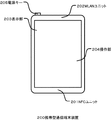
図2は、例えば、スマートホンのような携帯型通信端末装置200の正面図である。スマートホンとは、携帯電話の機能の他に、カメラやネットブラウザやメール機能などを搭載した多機能型の携帯電話のことである。
FIG. 2 is a front view of a portable
図2おいて、NFCユニット201はNFCを用いて通信を行うユニットであり、実際にNFCユニット201を相手先のNFCユニットに10cm程度以内に近づけることで通信を行うことができる。BTユニット202はBluetooth(登録商標)を用いた通信(BT通信)を行うためのユニットで装置内に配置されている。表示部203はLCDディスプレイで構成され、そのディスプレイ上に静電式タッチパネル方式の操作機構を備えた操作部204が配置される。操作部204はユーザの操作情報を検知する。代表的な操作方法は表示部203がボタン状のメニューを表示し、ユーザが操作部204に触れることによってボタン部分に関連付けられたイベントを発行し処理を実行することである。電源キー205は電源のオン/オフのために用いる。
In FIG. 2, the NFC unit 201 is a unit that performs communication using NFC, and communication can be performed by actually bringing the NFC unit 201 close to the counterpart NFC unit within about 10 cm. The BT unit 202 is a unit for performing communication (BT communication) using Bluetooth (registered trademark) and is arranged in the apparatus. The
図3はMFP300の概略構成を示す外観図である。図3において、(a)は外観斜視図であり、(b)はMFPの上面図である。
FIG. 3 is an external view showing a schematic configuration of the
原稿台301はガラス状の透明な台であり、原稿を載置してスキャナで読み取る時に使用する。原稿蓋302はスキャナで読み取りを行う際に読取光が外部に漏れないようにするための蓋である。印刷用紙挿入口303は様々なサイズの用紙をセットする挿入口である。ここにセットされた用紙は一枚ずつ印刷部(プリンタエンジン)に搬送され、所望の印刷を行って印刷用紙排出口304から排出される。 A document table 301 is a glassy transparent table, and is used when a document is placed and read by a scanner. A document cover 302 is a cover for preventing reading light from leaking to the outside when reading by the scanner. A printing paper insertion port 303 is an insertion port for setting paper of various sizes. The sheets set here are conveyed one by one to a printing unit (printer engine), and are printed out from a printing sheet discharge port 304 by performing desired printing.
原稿蓋302の上部には、(b)に示すように、操作部305とNFCユニット306が配置されている。操作表示部305には各種操作を行うキーやLCDディスプレイを備えており、MFP300に関する操作や設定が可能な構成となっている。NFCユニット306は近距離無線通信を行うためのユニットで実際に携帯型通信端末装置200を近接させる場所である。NFCユニット306から約10cmが通信可能な有効距離である。BTユニット307はBT通信を行うための通信モジュールであり、アンテナが埋め込まれている。なお、BTユニットの代わりにWLANユニットとそのアンテナが設けられていても良い。
An operation unit 305 and an NFC unit 306 are arranged on the upper portion of the document cover 302 as shown in FIG. The operation display unit 305 includes keys for performing various operations and an LCD display, and is configured to be able to perform operations and settings related to the
ともあれ、NFCユニットは非接触型近接通信に、BTユニット或いはWLANユニットは近距離無線通信に用いられる。 In any case, the NFC unit is used for non-contact proximity communication, and the BT unit or WLAN unit is used for short-range wireless communication.
図4はNFC通信におけるパッシブモードの概念を示すブロック図である。 FIG. 4 is a block diagram showing the concept of the passive mode in NFC communication.
図4(a)はイニシエータ401からターゲット402にデータ404をパッシブモードで送信する場合を示しており、イニシエータ401がRFフィールド(磁界)403を発生させる。イニシエータ401は、RFフィールド403を自ら変調することで、ターゲット402にデータ404を送信する。また、図4(b)は、ターゲット406からイニシエータ405にデータ408をパッシブモードで転送する場合を示しており、図4(a)と同様にイニシエータ405がRFフィールド407を発生させる。ターゲット406は、RFフィールド407に対して負荷変調を行うことで、イニシエータ405にデータ408を送信する。
FIG. 4A shows a case where data 404 is transmitted from the
図5はNFC通信におけるアクティブモードの概念を示すブロック図である。 FIG. 5 is a block diagram showing the concept of the active mode in NFC communication.
図5(a)はイニシエータ501からターゲット502にデータ504をアクティブモードで送信する場合を示しており、イニシエータ501がRFフィールド503を発生させる。イニシエータ501は、RFフィールド503を自ら変調することで、ターゲット502にデータ504を送信する。イニシエータ501はデータ送信完了後、RFフィールド503の発生を停止する。また、図5(b)はターゲット506からイニシエータ505にデータ508をアクティブモードで送信する場合を示しており、ターゲット506がRFフィールド507を発生させる。ターゲット506は自らが発するRFフィールド507によってデータ508を送信し、データ送信終了後、RFフィールド507の発生を停止する。
FIG. 5A shows a case where data 504 is transmitted from the
図6は携帯型通信端末装置200の構成を示すブロック図である。
FIG. 6 is a block diagram showing a configuration of the portable
携帯型通信端末装置200は、装置全体の制御を行うメインボード601と、WLAN通信を行うWLANユニット617と、NFC通信を行うNFCユニット618とBluetooth(登録商標)によりBT通信を行うBTユニット621からなる。なお、図6において、NFCユニット618とBTユニット621の通信相手先として携帯型通信装置が図示されているが、その通信相手先はこれに限定されるものではない。例えば、同じ通信プロトコルを備えた装置であれば、他の装置とも通信可能であることは言うまでもない。また、BTユニット621の代わりにWLANユニットを備える構成とし、例えば、IEEE802.1Xや802.11nに準拠したプロトコルを用いて高速な無線通信を行うようにしても良い。WLANユニット617、NFCユニット618、BTユニット621を総称して通信部という。
The portable
メインボード601においてCPU602は携帯型通信端末装置200の全体を制御するシステム制御部である。ROM603はCPU602が実行する制御プログラムや組み込みオペレーティングシステム(OS)プログラム等を格納する。この実施例では、ROM603に格納されている各制御プログラムは、ROM603に格納されている組み込みOSの管理下で、スケジューリングやタスクスイッチ等のソフトウエア制御を行う。RAM604はSRAM等で構成され、プログラム制御変数等を格納し、また、ユーザが登録した設定値や携帯型通信端末装置200の管理データ等を格納し、各種ワーク用バッファ領域として用いられる。
In the main board 601, a
画像メモリ605はDRAM等で構成され、通信部を介して受信した画像データや、データ蓄積部612から読みだした画像データをCPU602で処理するために一時的に格納する。不揮発性メモリ622はフラッシュメモリ等で構成され、電源がオフされた後でも保存しておきたいデータを格納する。例えば、電話帳データや、過去に接続したデバイス情報などがある。なお、メモリ構成は図6に示した構成に限定されるものではない。例えば、画像メモリ605とRAM604を共有させてもよいし、データ蓄積部612にデータのバックアップなどを行ってもよい。また、この実施例ではDRAMを用いているが、ハードディスクや不揮発性メモリ等を使用する場合もあるのでこの限りではない。
The
データ変換部606は、ページ記述言語(PDL)等の解析や、色変換、画像変換などのデータ変換を行う。電話部607は電話回線の制御を行い、スピーカ部613を介して入出力される音声データを処理することで電話による通信を実現している。操作部608は図2で説明した操作部204で発生した信号を制御している。GPS(全球測位システム)609は現在の緯度や経度などを取得する。表示部610は図2で説明した表示部203の表示内容を電子的に制御しており、各種入力操作や、MFP300の動作状況、ステータス状況の表示等を行う事ができる。
The
カメラ部611はレンズを介して入力された画像を電子的に記録して符号化する機能を有している。カメラ部611で撮影された画像はデータ蓄積部612に保存される。スピーカ部613は電話機能のための音声を入力または出力する機能や、その他アラーム通知などの機能を実現している。電源部614は携帯可能な電池と、その供給制御を行う。電源状態には、電池に残量が無い電池切れ状態、電源キー205を押下していない電源オフ状態、通常起動している起動状態(電源オン状態)、起動しているが省電力モードになっている省電力状態がある。
The
携帯型通信端末装置200にはMFPなどの他デバイスとのデータ通信を行う通信部として、3つの無線通信手段が搭載されており、WLAN、NFC、BlueTooth(商標登録)で無線通信することができる。通信部によりデータをパケットに変換し、他デバイスにパケット送信を行う。逆に、外部の他デバイスからのパケットを、データに変換してメインボード601に対して送信する。WLANユニット617、NFCユニット618、BTユニット621はそれぞれバスケーブル617、618、620で接続されている。WLANユニット617、NFCユニット618、BTユニット621は夫々の規格に準拠した通信を実現する。NFCユニットの詳細は後述する。
The portable
上記構成要素603〜614、617、618、621、622は、CPU602が管理するシステムバス619を介して、相互に接続されている。
The
図7は、MFP300の概略構成を示すブロック図である。
FIG. 7 is a block diagram illustrating a schematic configuration of the
MFP300は装置全体の制御を行うメインボード701と、WLAN通信を行うWLANユニット717と、NFC通信を行うNFCユニット718とBT通信を行うBTユニット719からなる。なお、図7において、NFCユニット718とBTユニット719の通信相手先として携帯型通信装置が図示されているが、その通信相手先はこれに限定されるものではない。例えば、同じ通信プロトコルを備えた装置であれば、他の装置とも通信可能であることは言うまでもない。また、BTユニット719の代わりにWLANユニットを備える構成とし、例えば、IEEE802.1Xや802.11nに準拠したプロトコルを用いて高速な無線通信を行うようにしても良い。WLANユニット717、NFCユニット718、BTユニット719を総称して通信部という。
The
メインボード701においてCPU702は、MFP300の全体を制御するシステム制御部である。ROM703はCPU702が実行する制御プログラムや組み込みオペレーティングシステム(OS)プログラム等を格納する。この実施例では、ROM703に格納されている各制御プログラムは、ROM703に格納されている組み込みOSの管理下で、スケジューリングやタスクスイッチ等のソフトウエア制御を行う。
In the main board 701, a
RAM704はSRAM等で構成され、プログラム制御変数等を格納し、また、ユーザが登録した設定値やMFP300の管理データ等を格納し、各種ワーク用バッファ領域としても用いられる。不揮発性メモリ705はフラッシュメモリ等で構成され、電源がオフされた時でも保持していたいデータを格納する。具体的にはネットワーク接続情報、ユーザデータなどである。画像メモリ706はDRAM等で構成され、通信部を介して受信した画像データや、符号復号化処理部712で処理した画像データや、メモリカードコントローラ(不図示)を介してメモリカードから取得した画像データなどを蓄積する。また、携帯型通信端末装置200のメモリ構成と同様に、メモリ構成はこれに限定されるものではない。データ変換部707は、ページ記述言語(PDL)等の解析や画像データからプリントデータへの変換などを行う。
The
読取制御部708により制御される読取部710がCISイメージセンサによって原稿を光学的に読み取ることで発生した画像信号には画像処理制御部(不図示)を介して、2値化処理や中間調処理等の各種画像処理が施され、高精細な画像データを出力する。
The image signal generated when the reading unit 710 controlled by the
操作部709、表示部711は図4で説明した操作表示部305を表している。符号復号化処理部712は、MFP300で扱う画像データ(JPEG、PNG等)に対して符号復号化処理や拡大縮小処理を行う。
An operation unit 709 and a
給紙部715は記録用紙などの記録媒体を保持する。給紙動作は記録制御部716からの制御により給紙部715により行うことができる。特に、給紙部は複数種類の用紙を一つの装置に保持するために、複数の給紙部から構成されても良い。この場合、記録制御部716により、どの給紙部から給紙を行うかを選択制御する。
A paper feed unit 715 holds a recording medium such as a recording sheet. The paper feeding operation can be performed by the paper feeding unit 715 under the control of the
記録制御部716は、記録に用いられる画像データに対し、画像処理制御部(不図示)を介して、スムージング処理や記録濃度補正処理、色補正等の各種画像処理を施し、高精細な画像データに変換し、記録部715に出力する。また、記録制御部716は記録部715の情報を定期的に読みだしてRAM704に格納される状態情報を更新する。具体的にはインクタンクの残量や記録ヘッドの状態などを更新する。
The
MFP300にも携帯型通信端末装置200と同様に3つの無線通信手段が搭載されているが、各機能は携帯型通信端末装置200のそれと同じであるため、その説明は省略する。なお、WLANユニット717、NFCユニット718、BTユニット719はそれぞれバスケーブル720、721、722で接続されている。
The
上記構成要素702〜719は、CPU702が管理するシステムバス723を介して、相互に接続されている。
The
図8はNFCユニット618やNFCユニット718で使用されているNFCユニットの詳細な構成を示すブロック図である。
FIG. 8 is a block diagram showing a detailed configuration of the NFC unit used in the NFC unit 618 and the
NFCユニット800は、NFCコントローラ部801と、アンテナ部802と、RF部803と、送受信制御部804と、NFCメモリ805と、デバイス接続部807を有する。電源806はNFCユニット800の外部から供給される。アンテナ部802は、他のNFCデバイスから電波や搬送波を受信したり、他のNFCデバイスに電波や搬送波を送信したりする。RF部803はアナログ信号をデジタル信号に変復調する機能を備えている。RF部803はシンセサイザを備えていて、バンド、チャネルの周波数を識別し、周波数割り当てデータによるバンド、チャネルの制御をしている。送受信制御部804は送受信フレームの組み立て及び分解、プリアンブル付加及び検出、フレーム識別など、送受信に関する制御をおこなう。また、送受信制御部804はNFCメモリ805の制御も行い、各種データやプログラムを入出力する。
The NFC unit 800 includes an NFC controller unit 801, an
NFCメモリ805は不揮発性メモリから構成され、デバイス接続部807から通信された、接続されたデバイスに関する情報などのデータを保存することも可能である。アクティブモードとして動作する場合、電源806を介して電力の供給を受け、デバイス接続部807を通じてデバイスと通信を行ったり、アンテナ部801を介して送受信される搬送波により、通信可能な範囲にある他のNFCデバイスと通信する。これに対して、パッシブモードとして動作する場合、アンテナ部802を介して他のNFCデバイスから電波を受信して電磁誘導により他のNFCデバイスから電力供給を受ける。そして、搬送波の変調により当該他のNFCデバイスとの間で通信を行い、NFCメモリ805に記憶されている情報を含むデータを送受信する。
The
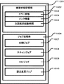
図9はMFP300のRAM704の内部構成を示すブロック図である。
FIG. 9 is a block diagram showing an internal configuration of the
図9において、901はRAM全体を表している。ワークメモリ902はプログラムの実行のために確保される領域である。画像処理バッファ903は画像処理のために一時的なバッファとして使用される領域である。機器状態記憶部904はMFP300の現在の状態に関する様々な情報が記憶されている。エラー状態905はMFP300のエラーに関する状態を記憶している。インク少警告、インク無エラー、紙ジャムエラー、用紙無し警告、記録画像不良警告、読取画像不良エラー、ネットワーク切断警告などがある。
In FIG. 9,
これらの警告やエラーには記録機能への影響度、読取機能への影響度などが関連付けられている。例えば、インク無エラーの場合、記録機能は使用できないが、読取機能は使用できる。ネットワーク切断警告の場合、ネットワークを使う機能は使用できないが、機器単体で行う設定変更や読取機能は使用できる。インク残量906には現在取り付けられているインクタンクの型番やインク残量が記憶されている。インクタンクの型番はインクタンクが取り付けられたタイミングで更新される。インク残量はインクが使用される毎に更新される。次回推定起動時間907は電源がオフされた時に、次に起動する時の推定起動時間が記憶されている。
These warnings and errors are associated with the degree of influence on the recording function and the degree of influence on the reading function. For example, when there is no ink error, the recording function cannot be used, but the reading function can be used. In the case of a network disconnection warning, the function that uses the network cannot be used, but the setting change or reading function that is performed by a single device can be used. The remaining
MFPの起動時間は状態によって大きく異なる。例えば、MFPの電源状態はハードオフ状態、ソフトオフ状態、通常起動状態(通常モード)、スリープ状態(省電力モード)などが存在する。ハードオフ状態は電力供給が途絶えている状態であり、電源ケーブルを接続するとハードオフ状態かブートシーケンスによる初期化処理を経てソフトオフ状態にする。ソフトオフ状態は部分的には電源は投入されているが、メインボードのプログラムは起動していない状態である。スリープ状態では装置の電源消費が大きな部分(モジュール)がオフにされており、それ以外のプログラムや機構部は動作しているため、直ぐに通常起動状態に復帰することができる。上記電源状態によりMFPに搭載されている各通信モジュールの省電力状態に応じて、通信が可能になるまでの起動時間が異なる。例えば、MFPがソフトオフ状態であれば、メインボードのプログラム起動を経て各モジュールへの電源供給が行われてから通信が可能となる。またスリープ状態で通信モジュールを省電力状態にしているケースにおいては各通信モジュールの起動に要する時間が必要となる。 The activation time of the MFP varies greatly depending on the state. For example, the power state of the MFP includes a hard-off state, a soft-off state, a normal activation state (normal mode), a sleep state (power saving mode), and the like. The hard-off state is a state in which power supply is interrupted. When the power cable is connected, the hard-off state or the soft-off state is set through an initialization process by a boot sequence. The soft off state is a state in which the power is turned on partially but the main board program is not activated. In the sleep state, a portion (module) that consumes a large amount of power of the apparatus is turned off, and other programs and mechanisms are operating, so that the normal startup state can be immediately restored. Depending on the power state, the activation time until communication is possible differs depending on the power saving state of each communication module installed in the MFP. For example, if the MFP is in a soft-off state, communication can be performed after power is supplied to each module after the main board program is started. In the case where the communication module is in the power saving state in the sleep state, time required for starting each communication module is required.
また、起動時間が変動する別の要因として、機器のエラー状態がある。例えば、インクジェット記録ヘッドのノズルの目詰まりが多いと検知した時は、次の起動で長時間の回復処理を行ってから通常起動状態に復帰する。また、スキャナの光量が落ちている時は調整動作を行ってから通常起動状態に復帰する。このように電源の状態遷移や機器の状態によって次に起動する時の推定起動時間が決定される。その他908には現在のメモリ使用量、ハードウェアの温度、消耗品情報など、その他の機器状態が格納されている。その他909にはその他のRAMのデータも格納されている。 Another factor that varies the startup time is the error state of the device. For example, when it is detected that the nozzles of the ink jet recording head are clogged frequently, the recovery is performed for a long time at the next activation, and then the normal activation state is restored. When the amount of light of the scanner is low, the adjustment operation is performed and then the normal activation state is restored. Thus, the estimated activation time for the next activation is determined according to the state transition of the power source and the state of the device. The other 908 stores other device states such as the current memory usage, hardware temperature, and consumable information. The other 909 stores other RAM data.
図10はMFP300のNFCメモリ805の構成を示すブロック図である。
FIG. 10 is a block diagram showing the configuration of the
図10において、1001はNFCメモリ全体を表している。CPU702は機器状態記憶部1002に所定のタイミングで機器状態記憶部904の内容(エラー状態、インク残量、次回推定起動時間)をコピーする。また、その他908の領域に格納された、例えば、ジョブの記憶など任意のデータをコピーしても良い。
In FIG. 10,
ジョブ記憶部1006は携帯型通信端末装置200からNFCでジョブをMFP300に投入する場合に使用する領域である。印刷ジョブ1007は印刷ジョブがキューで格納されている。具体的には、印刷設定や画像データへのリンク先が格納される。スキャンジョブ1008はスキャンジョブがキューで格納されている。具体的には、読取設定が格納される。FAXジョブ1009はFAXジョブがキューで格納されている。具体的には、送信先の電話番号や通信画質などが含まれるFAX設定、そして、画像が既に読み取ってある場合は画像へのリンク先が格納される。設定変更ジョブ1010には設定変更ジョブがキューで格納されている。具体的には、MFP本体の設定項目の変更に関するジョブが格納される。
A
図11はNFCユニットがイニシエータとして動作する場合のフローチャートである。 FIG. 11 is a flowchart when the NFC unit operates as an initiator.
まず、ステップS1101では、すべてのNFCユニットはターゲットとして動作し、イニシエータからの命令を待っている状態になる。次にステップS1102では、NFCユニットは、NFC規格による通信を制御するアプリケーションからの要求でイニシエータに切り替わることができる。NFCユニットがイニシエータに切り替わる要求に応じた場合、処理はステップS1103に進み、アプリケーションは、アクティブモードまたはパッシブモードのどちらかを選択し、伝送速度を決める。 First, in step S1101, all NFC units operate as targets and wait for a command from the initiator. Next, in step S1102, the NFC unit can be switched to the initiator in response to a request from an application that controls communication according to the NFC standard. If the NFC unit responds to the request to switch to the initiator, the process proceeds to step S1103, and the application selects either the active mode or the passive mode, and determines the transmission speed.
次にステップS1104では、イニシエータは自装置以外が出力するRFフィールドの存在を検知する。外部のRFフィールドが存在した場合は、イニシエータは自らのRFフィールドは発生させない。外部のRFフィールドが存在しなかった場合には、処理はステップS1105に進み、イニシエータは自らのRFフィールドを発生させる。 In step S1104, the initiator detects the presence of an RF field output by a device other than itself. If there is an external RF field, the initiator does not generate its own RF field. If there is no external RF field, the process proceeds to step S1105, and the initiator generates its own RF field.
以上のステップを経て、NFCユニットはイニシエータとして動作を開始する。 Through the above steps, the NFC unit starts operating as an initiator.
図12はパッシブモードによるデータ交換を行うシーケンスを示す図である。ここでは、NFCユニット(第1のNFCユニット)1201がイニシエータ、NFCユニット(第2のNFCユニット)1202がターゲットとして動作する場合について説明する。 FIG. 12 is a diagram showing a sequence for exchanging data in the passive mode. Here, a case where the NFC unit (first NFC unit) 1201 operates as an initiator and the NFC unit (second NFC unit) 1202 operates as a target will be described.
まず、ステップS1201では、NFCユニット1201は単一デバイス検知を行い、NFCユニット1202を特定する。次にステップS1202では、NFCユニット1201は属性要求として自身の識別子や送受信のビット伝送速度、有効データ長などを送信する。また、この属性要求は汎用バイトを有しており、汎用バイトを任意に選択して使用することができる。有効な属性要求を受信した場合、NFCユニット1202はステップS1203として属性応答を送信する。ここで、NFCユニット1202からの送信は負荷変調によって行われており、図中では負荷変調によるデータ送信は点線の矢印で表現している。 First, in step S1201, the NFC unit 1201 performs single device detection and identifies the NFC unit 1202. In step S1202, the NFC unit 1201 transmits its own identifier, transmission / reception bit transmission rate, effective data length, and the like as an attribute request. This attribute request has a general-purpose byte, and the general-purpose byte can be arbitrarily selected and used. When a valid attribute request is received, the NFC unit 1202 transmits an attribute response as step S1203. Here, transmission from the NFC unit 1202 is performed by load modulation, and data transmission by load modulation is represented by dotted arrows in the drawing.
有効な属性応答を確認した後、NFCユニット1201は、ステップS1204で、パラメータ選択要求を送信して、引き続く伝送プロトコルのパラメータを変更することができる。パラメータ選択要求に含まれるパラメータは、伝送速度と有効データ長である。NFCユニット1202は、有効なパラメータ選択要求を受信した場合、ステップS1205においてパラメータ選択応答を送信し、パラメータを変更する。なお、ステップS1204〜S1205は、パラメータ変更を行わない場合は省略しても良い。 After confirming the valid attribute response, the NFC unit 1201 can change the parameters of the subsequent transmission protocol by transmitting a parameter selection request in step S1204. Parameters included in the parameter selection request are a transmission rate and an effective data length. When receiving a valid parameter selection request, the NFC unit 1202 transmits a parameter selection response in step S1205 to change the parameter. Note that steps S1204 to S1205 may be omitted when parameter change is not performed.
次にステップS1206において、NFCユニット1201とNFCユニット1202は、データ交換要求とデータ交換応答によってデータの交換を行う。データ交換要求とその応答では、通信相手が有するアプリケーションに対する情報などをデータとして伝送することができ、データサイズが大きい場合には分割して送信することもできる。 In step S1206, the NFC unit 1201 and the NFC unit 1202 exchange data by a data exchange request and a data exchange response. In the data exchange request and its response, information on the application of the communication partner can be transmitted as data, and when the data size is large, it can be divided and transmitted.
データ交換が終了するとステップS1207において、NFCユニット1201は、選択解除要求または解放要求のどちらかを送信する。選択解除要求を送信した場合、NFCユニット1202はステップS1208で選択解除応答を送信する。NFCユニット1201は、選択解除応答を受け取ると、NFCユニット1202を示す属性を解放してステップS1201に戻る。これに対して、解放要求を送信した場合、NFCユニット1202は、ステップS1208で解放応答を送信して初期状態へ戻る。NFCユニット1201は解放応答を受け取った場合、ターゲットは完全に解放されているので、初期状態へ戻ることができる。 When the data exchange is completed, in step S1207, the NFC unit 1201 transmits either a selection cancellation request or a release request. When the selection cancellation request is transmitted, the NFC unit 1202 transmits a selection cancellation response in step S1208. Upon receiving the selection cancellation response, the NFC unit 1201 releases the attribute indicating the NFC unit 1202 and returns to step S1201. On the other hand, when the release request is transmitted, the NFC unit 1202 transmits a release response in step S1208 and returns to the initial state. When the NFC unit 1201 receives the release response, the target has been completely released and can return to the initial state.
図13はアクティブモードによるデータ交換を行うシーケンスを示す図である。ここでは、NFCユニット1301(第1のNFCユニット)がイニシエータ、NFCユニット(第2のNFCユニット)1302がターゲットとして動作している場合について説明する。 FIG. 13 is a diagram showing a sequence for exchanging data in the active mode. Here, a case where the NFC unit 1301 (first NFC unit) operates as an initiator and the NFC unit (second NFC unit) 1302 operates as a target will be described.
まず、ステップS1301では、NFCユニット1301は属性要求として自身の識別子や送受信のビット伝送速度、有効データ長などを送信する。ユニット1302は、有効な属性要求を受信した場合、ステップS1302において属性応答を送信する。ここで、NFCユニット1302からの送信は自らの発したRFフィールドによって行われる。このため、両方のNFCユニットは、データ送信が終了するとRFフィールドの発生を停止する。 First, in step S1301, the NFC unit 1301 transmits its own identifier, transmission / reception bit transmission rate, effective data length, and the like as an attribute request. If the unit 1302 receives a valid attribute request, the unit 1302 transmits an attribute response in step S1302. Here, transmission from the NFC unit 1302 is performed by an RF field generated by itself. For this reason, both NFC units stop generating the RF field when the data transmission is completed.
有効な属性応答を確認後、NFCユニット1301は、ステップS1303において、パラメータ選択要求を送信して伝送プロトコルのパラメータを変更することができる。パラメータ選択要求に含まれるパラメータは、伝送速度と有効データ長である。NFCユニット1302は、有効なパラメータ選択要求を受信した場合、ステップS1304においてパラメータ選択応答を送信し、パラメータを変更する。なお、パッシブモードの場合と同様に、ステップS1303〜S1304は、パラメータ変更を行わない場合は省略しても良い。 After confirming the valid attribute response, the NFC unit 1301 can change the parameters of the transmission protocol by transmitting a parameter selection request in step S1303. Parameters included in the parameter selection request are a transmission rate and an effective data length. When receiving a valid parameter selection request, the NFC unit 1302 transmits a parameter selection response in step S1304 and changes the parameter. As in the passive mode, steps S1303 to S1304 may be omitted if no parameter change is performed.
次にステップS1305において、NFCユニット1301とNFCユニット1302は、データ交換要求とデータ交換応答によってデータの交換を行う。データ交換要求とその応答は、アプリケーションに対する情報などをデータとして伝送することができ、データサイズが大きい場合には分割して送信することもできる。 In step S1305, the NFC unit 1301 and the NFC unit 1302 exchange data by a data exchange request and a data exchange response. The data exchange request and the response can be transmitted as information on the application as data, and can be divided and transmitted when the data size is large.
データ交換が終了すると、処理はステップS1306において、NFCユニット1301は選択解除要求または解放要求のどちらかを送信する。選択解除要求を送信した場合、NFCユニット1302はステップS1307で選択解除応答を送信する。NFCユニット1301は選択解除応答を受け取るとNFCユニット1302を示す属性を解放する。その後、ステップS1308において、NFCユニット1301は、識別子が既知な別のターゲットに対して起動要求を送信する。起動要求を受けたターゲットは、起動応答をステップS1309において送信し、その後、処理はステップS1301に戻る。これに対して、解放要求を送信した場合、NFCユニット1302は、ステップS1309で解放応答を送信して初期状態へ戻る。NFCユニット1301は解放応答を受け取れば、ターゲットは完全に解放されているので、初期状態へ戻ることができる。 When the data exchange is completed, in step S1306, the NFC unit 1301 transmits either a selection cancellation request or a release request. When the selection cancellation request is transmitted, the NFC unit 1302 transmits a selection cancellation response in step S1307. When the NFC unit 1301 receives the selection cancellation response, the attribute indicating the NFC unit 1302 is released. Thereafter, in step S1308, the NFC unit 1301 transmits an activation request to another target whose identifier is known. The target that has received the activation request transmits an activation response in step S1309, and then the process returns to step S1301. On the other hand, when a release request is transmitted, the NFC unit 1302 transmits a release response in step S1309 and returns to the initial state. If the NFC unit 1301 receives the release response, the target has been completely released and can return to the initial state.
図14はNFCにおけるターゲットの状態遷移を表した図である。 FIG. 14 is a diagram showing target state transition in NFC.
図14において、POWER−OFF状態であるS2301は、電源切断の状態を表している。状態S2301において、ターゲットは閾値Hminよりも大きな磁場Hの中に置かれている場合はSENSE状態であるS2302に移行する。 In FIG. 14, S2301 which is a POWER-OFF state represents a power-off state. In the state S2301, when the target is placed in the magnetic field H larger than the threshold value Hmin, the process proceeds to S2302 which is the SENSE state.
状態S2302において、ターゲットはイニシエータからの命令を待ち受けている。ターゲットは、検知要求または全デバイス起動要求を受け取った場合、RESOLUTION状態であるS2303に移行して検知応答を返す。他の命令を受け取った場合は、そのままSENSE状態のS2302にとどまる。 In state S2302, the target is waiting for an instruction from the initiator. When the target receives the detection request or the all device activation request, the target shifts to S2303 which is a RESOLUTION state and returns a detection response. If another instruction is received, the process stays at S2302 in the SENSE state.
状態S2303では単一デバイス検出が用いられる。単一デバイス検出の結果として、有効な選択要求を受け取った場合、ターゲットは選択応答をイニシエータに返してSELECTED状態であるS2304になる。他の命令を受け取った場合は、SENSE状態S2302に戻る。 In state S2303, single device detection is used. When a valid selection request is received as a result of the single device detection, the target returns a selection response to the initiator, and becomes S2304 in the SELECTED state. If another command is received, the process returns to the SENSE state S2302.
状態S2304において、ターゲットは、属性要求、パラメータ選択要求、または有効な独自仕様の命令を認識する。ターゲットは、有効な休止要求または選択解除要求を受け取った場合、SLEEP状態であるS2305になる。その他の命令を受け取った場合には、SENSE状態S2302に戻る。 In state S2304, the target recognizes an attribute request, a parameter selection request, or a valid proprietary instruction. When the target receives a valid sleep request or deselection request, the target enters S2305 which is a SLEEP state. If any other command is received, the process returns to the SENSE state S2302.
状態S2305において、ターゲットは、全デバイス起動要求を受け取った場合、検知応答を返してからRESOLUTION*状態であるS2306に移行する。他の命令を受け取った場合は、そのままSLEEP状態であるS2305にとどまる。 In the state S2305, when the target receives all device activation requests, the target returns a detection response and then proceeds to S2306 in the RESOLUTION * state. If another command is received, the process stays at S2305 in the SLEEP state.
RESOLUTION*状態であるS2306はRESOLUTION状態であるS2303とほぼ同じ状態であり単一デバイス検出が用いられる。有効な選択要求を受け取った場合、ターゲットはSELECTED*状態であるS2307に遷移する。その他の命令を受け取った場合は、SLEEP状態であるS2305に戻る。 S2306 in the RESOLUTION * state is almost the same as S2303 in the RESOLUTION state, and single device detection is used. If a valid selection request is received, the target transitions to S2307 which is a SELECTED * state. If any other command is received, the process returns to S2305 which is the SLEEP state.
SELECTED*状態であるS2307はSELECTED状態であるS2304とほぼ同じ状態であり、ターゲットは、属性要求、パラメータ選択要求、または有効な独自仕様の命令を認識する。有効な休止要求または選択解除要求を受け取った場合は、SLEEP状態に遷移する。その他の命令を受け取った場合は、SLEEP状態にフォールバックする。 S2307 being the SELECTED * state is almost the same state as S2304 being the SELECTED state, and the target recognizes an attribute request, a parameter selection request, or a valid proprietary instruction. When a valid sleep request or selection cancel request is received, the state transits to the SLEEP state. If any other instruction is received, it falls back to the SLEEP state.
次に以上のような構成の記録システムにおいて、携帯型通信端末装置200からMFP300に対する印刷の指示を行った場合の処理について説明する。
Next, in the recording system configured as described above, a process when a print instruction is issued from the portable
図15はMFP300の電力状態変更時におけるNFCユニットに対する制御動作を示すフローチャートである。
FIG. 15 is a flowchart showing a control operation for the NFC unit when the power state of the
ステップS1401において電力状態変更処理に入ると、ステップS1402では、MFPの動作モードが通常モードへの移行か省電力モードへの移行であるかを判定する。ここで、通常モードへの移行であると判定された場合には、処理はステップS1404に進む。この場合、BT通信がすぐに開始可能な状態であるため、MFPのBT通信の起動に関する時間情報をクリアし、NFCメモリ805に起動時間を書き込む。その後、電力状態変更処理を終了する。
If the power state change process is entered in step S1401, it is determined in step S1402 whether the operation mode of the MFP is the transition to the normal mode or the power saving mode. Here, if it is determined that the transition is to the normal mode, the process proceeds to step S1404. In this case, since the BT communication can be started immediately, the time information regarding the activation of the BT communication of the MFP is cleared and the activation time is written in the
これに対して、ステップS1402において省電力モードへの移行であると判定された場合、処理はステップS1403に進み、省電力モードの内容に応じてBTユニット719の状態を省電力モードにするか電源OFF状態にするかを判断する。ここで、省電力モードにすると判定された場合、処理はステップS1405に進み、省電力モードから通信復帰に要する起動時間をNFCメモリ805に書き込み、その後、電力状態変更処理を終了する。これに対して、BTユニット719を電源OFFすると判定された場合、処理はステップS1406に進み、MFPの起動に関する状態を加味して、電源OFF状態から通信が開始可能な状態となる時間をNFCメモリ805に書き込む。その後、電力状態変更処理を終了する。
On the other hand, if it is determined in step S1402 that the mode is the transition to the power saving mode, the process proceeds to step S1403, and the state of the BT unit 719 is set to the power saving mode according to the content of the power saving mode. It is determined whether to turn off. If it is determined to enter the power saving mode, the process advances to step S1405 to write the activation time required for returning from the power saving mode to the
なお、以上の説明では、BT通信起動に関する起動時間をNFCメモリに記憶する例について説明したが、他の通信プロトコル(例えば、IEEE802.1x,802.11n)に関する起動時間について記憶しても同様の効果を得ることができる。 In the above description, the example in which the activation time relating to the BT communication activation is stored in the NFC memory has been described. However, the activation time relating to another communication protocol (for example, IEEE 802.1x, 802.11n) may be stored similarly. An effect can be obtained.
次に携帯型通信端末装置から省電力モードにあるMFPへ画像データを送信する例について説明する。 Next, an example in which image data is transmitted from the portable communication terminal apparatus to the MFP in the power saving mode will be described.
図16は携帯型通信端末装置において画像データ送信アプリケーションを起動した場合の表示画面の例を示す図である。 FIG. 16 is a diagram illustrating an example of a display screen when an image data transmission application is activated in the portable communication terminal device.
アプリケーションを起動すると最初に、図16(a)に示す画像選択画面が表示され、タッチパネル表示画面203には画像データのサムネイル1501が表示され、ユーザが所望の画像を選択できる状態となる。選択された画像にはフォーカス1502が当てられる。このアプリケーションでは画像選択以外にも画像を拡大縮小表示や、撮影日などの画像情報なども確認出来る構成となっている(不図示)。
When the application is activated, an image selection screen shown in FIG. 16A is displayed first, and a thumbnail 1501 of the image data is displayed on the touch
さて、ユーザが1つまたは複数の画像を選択し、印刷開始キー1503を選択するとBTユニット202を介して、照会要求(Inquiry Request)によりMFPを検索し、検索されたMFPを表示画面上に表示する。図16(b)には検索されたMFPは表示部203に表示される例が示されている。
When the user selects one or a plurality of images and selects the print start key 1503, the MFP is searched by an inquiry request (Inquiry Request) via the BT unit 202, and the searched MFP is displayed on the display screen. To do. FIG. 16B shows an example in which the searched MFP is displayed on the
このような処理を実行する一方、BT通信によるプリンタ検索と同時にNFC通信のためにNFCユニット201のアンテナの周囲にRFフィールドを生成し、近傍のMFP上のターゲットを検索する。携帯型通信端末装置をMFPの近傍に配置することにより、NFC通信によりターゲットとなるMFPが見い出されると、BT通信の照会要求(Inquiry Request)による機器探索を停止する。この例ではMFP側のBTユニットは省電力モードにあるために照会要求(Inquiry Request)には応答せずに、NFCユニットによる電磁誘導による起動でのみ応答が可能な状態となっている。 While performing such processing, simultaneously with the printer search by BT communication, an RF field is generated around the antenna of the NFC unit 201 for NFC communication, and a target on a nearby MFP is searched. By disposing the portable communication terminal device in the vicinity of the MFP, when a target MFP is found by NFC communication, the device search by the BT communication inquiry request is stopped. In this example, since the BT unit on the MFP side is in the power saving mode, it does not respond to an inquiry request (Inquiry Request), but can respond only by activation by electromagnetic induction by the NFC unit.
図17は携帯型通信端末装置とMFPとのプッシュ型通信に関するシーケンスを示す図である。 FIG. 17 is a diagram showing a sequence relating to push-type communication between the portable communication terminal device and the MFP.
このシーケンスによれば、ステップS1601では携帯型通信端末装置は画像を送信する機器を探索するためにNFC通信によりポーリングを行う。このポーリングに対してステップS1602においてMFP上のNFCユニットからの応答が返ると、携帯型通信端末装置はターゲットが見つかったと判断して、ステップS1603では自身のNFC_IDを含めたNFC_ID要求を行う。ステップS1604ではMFPはこの要求を受信し、自身のNFC_IDを送信することにより応答する。このようにして、携帯型通信端末装置とMFPはそれぞれ受信したNFC_IDにより通信相手を特定する。 According to this sequence, in step S1601, the portable communication terminal device performs polling by NFC communication in order to search for a device that transmits an image. When a response from the NFC unit on the MFP is returned in step S1602 in response to this polling, the portable communication terminal apparatus determines that a target has been found, and makes an NFC_ID request including its own NFC_ID in step S1603. In step S1604, the MFP receives this request and responds by transmitting its own NFC_ID. In this way, the portable communication terminal device and the MFP each specify a communication partner based on the received NFC_ID.
その後、ステップS1605では相互機器間のキー交換による認証要求を、ステップS1606では認証応答を実行し、相互認証が確立されるとともにその後の通信の暗号化が行われる。 After that, in step S1605, an authentication request by exchanging keys between the mutual devices is executed, and in step S1606, an authentication response is executed, whereby mutual authentication is established and subsequent communication is encrypted.
次にステップS1607では携帯型通信端末装置から利用可能な他のプロトコルに関する情報の要求を行う。MFPはこの要求を受け付けると、処理はステップS1608においてMFP自身が利用可能な他のプロトコルに関する情報(BT通信を含む)を応答する。携帯型通信端末装置では受信したプロトコル情報を元に、画像データの送信に適したプロトコルとして返答されたBT通信を選択する。 In step S1607, a request is made for information relating to another protocol that can be used from the portable communication terminal device. Upon receiving this request, the MFP responds with information (including BT communication) regarding other protocols that can be used by the MFP itself in step S1608. Based on the received protocol information, the portable communication terminal device selects BT communication returned as a protocol suitable for transmission of image data.
さらにステップS1609では、携帯型通信端末装置はMFPとのBT通信接続に必要なBluetoothデバイスアドレス(BD_ADDR)やパスキー、リンクキーに関する情報及びBT通信に必要な起動時間情報を要求する。これに対して、ステップS1610では、MFPのNFCユニット718はNFCメモリ内の起動情報1005に基づいてBT通信接続に必要な情報を応答する。なお、起動情報1005は、図15に示した処理により、NFCメモリ805に書き込まれている。省電力モードにあるMFPがNFCユニットにより通信が開始されるとNFCメモリ上のジョブ記憶部1006の印刷ジョブ1007にBT通信ジョブが開始されることを記憶する。また同時に、NFCユニットからのデバイス通信により省電力モードからの復帰処理を開始する。
In step S1609, the portable communication terminal requests a Bluetooth device address (BD_ADDR) necessary for BT communication connection with the MFP, information on a pass key and link key, and activation time information necessary for BT communication. In contrast, in step S1610, the
MFPの起動処理では印刷ジョブ1007に記憶されたBT接続でハンドオーバするという情報によりBTユニット719を同時に起動する。携帯型通信端末装置は受信したBT接続情報に基づいて、MFP側の起動時間の経過を待つ。MFP起動時間を待っている間、携帯型通信端末装置はユーザに対して、MFPが起動中である旨を表示する。
In the MFP activation process, the BT unit 719 is activated at the same time based on the information that the BT connection stored in the
そして、MFP起動時間経過後、ステップS1611において、携帯型通信端末装置はMFPにBT接続を要求する。ステップS1612において、MFPは接続要求に応答することによりBTリンク接続が確立する。携帯型通信端末装置はステップS1613〜S1614においてBT通信によりMFPに選択された画像データを送信する。BT通信による送信が開始されると画像データ送信を示すために、携帯型通信端末装置は図16(c)に示すように、印刷画像情報やデータ転送状態を含んだ印刷状態表示画面を表示部203に表示する。一方、MFPはBT通信で受信した画像データに基づいて画像の印刷を開始する。 Then, after the MFP activation time has elapsed, in step S1611, the portable communication terminal apparatus requests the BT connection to the MFP. In step S1612, the MFP responds to the connection request to establish a BT link connection. The portable communication terminal device transmits the image data selected by the BT communication to the MFP in steps S1613 to S1614. In order to indicate image data transmission when transmission by BT communication is started, the portable communication terminal device displays a print status display screen including print image information and data transfer status as shown in FIG. 203. On the other hand, the MFP starts printing an image based on the image data received by BT communication.
以上説明した実施例に従えば、省電力モードにあるMFPに対して通信が可能なNFC通信で印刷ジョブの存在を通知しMFPが通常モードに復帰後に高速なBT通信を起動してハンドオーバを行い、通信プロトコルを切り換えてデータ送信を行うことができる。 According to the embodiment described above, the existence of a print job is notified by NFC communication capable of communication to the MFP in the power saving mode, and after the MFP returns to the normal mode, the high-speed BT communication is started to perform handover. Data transmission can be performed by switching the communication protocol.
なお、以上説明した例では高速通信としてBT通信を用いたが、BT通信以外にもIEEE802.1XやIEEE802.11nなどの他のプロトコルを用いたWLAN通信などによりデータを送信しても良い。 In the example described above, the BT communication is used as the high-speed communication. However, in addition to the BT communication, data may be transmitted by WLAN communication using other protocols such as IEEE 802.1X and IEEE 802.11n.
また、ステップS1610とステップS1611との間ではユーザはMFPが通常モードに復帰してBT通信が可能な状態になるまで待ち合わせる必要がある。その場合。ユーザがその待ち合わせを行いたくない場合には、以下のような処理を行っても良い。即ち、携帯型通信端末装置のアプリケーションに待ち合わせ時間の上限値を設定しておき、その上限値を待ち合わせ時間が超えたなら、タイムアウトとして画像データの送信を実行しないようにすることができる。或いは、ステップS1610でMFPより送信された待ち合わせ時間を表示部203に表示し、ユーザがこれに対して画像データの送信中止の応答をMFPにNFCにより返信して印刷ジョブの中止を通知することもできる。
Further, between step S1610 and step S1611, the user needs to wait until the MFP returns to the normal mode and becomes ready for BT communication. In that case. If the user does not want to wait, the following processing may be performed. In other words, an upper limit value of the waiting time is set in the application of the portable communication terminal device, and if the waiting time exceeds the upper limit value, image data transmission can be prevented from being executed as a timeout. Alternatively, the waiting time transmitted from the MFP in step S1610 is displayed on the
<他の実施例>
前述の実施例ではBT通信によるいわゆるプッシュ型通信により画像データを送信する手順について説明しているが、プル型通信によりMFP側からデータを取得しにいくようにしても良い。
<Other embodiments>
In the above-described embodiment, the procedure for transmitting image data by so-called push type communication by BT communication has been described. However, data may be acquired from the MFP side by pull type communication.
図18は携帯型通信端末装置とMFPとのプル型通信に関するシーケンスを示す図である。なお、図18において、既に図17を用いて説明したのと同じステップについては同じステップ参照番号を付し、その説明は省略する。 FIG. 18 is a diagram showing a sequence relating to pull-type communication between the portable communication terminal device and the MFP. In FIG. 18, the same steps as those already described with reference to FIG. 17 are denoted by the same step reference numerals, and the description thereof is omitted.
図18における特徴的なステップはステップS1611’〜S1616’である。携帯型通信端末装置がステップS1610で受信したBT状態情報応答を受けて即座にBT通信にハンドオーバ出来ないと判断しプル型通信を選択した場合、次の処理を行う。即ち、画像印刷に関する、画像のパス情報を含むファイル情報などをジョブ情報としてMFPのNFCメモリのジョブ記憶部1006の印刷ジョブ1007に書き込みを要求する(ステップS1611’)。これに対して、ステップS1612’ではMFPから応答する。
Characteristic steps in FIG. 18 are steps S1611 'to S1616'. When the portable communication terminal apparatus receives the BT state information response received in step S1610 and determines that it cannot immediately perform handover to BT communication and selects pull-type communication, the following processing is performed. That is, it requests the
NFCによる通信により認証終了後、ステップS1613’ではMFPからBT接続要求を行うと、ステップS1614’では携帯型通信端末装置がこれに対して接続応答する。これに応じて、ステップS1615’ではMFPがNFC通信により受信したジョブ情報を元に画像データ送信要求を行うと、ステップS1616’では携帯型通信端末装置がこれに対して画像データを送信する。 After completion of authentication by NFC communication, when a BT connection request is made from the MFP in step S1613 ', the portable communication terminal device responds to the connection in step S1614'. In response to this, in step S1615 ', when the MFP makes an image data transmission request based on the job information received by NFC communication, in step S1616', the portable communication terminal device transmits image data thereto.
図19は図18のシーケンスに関連した携帯型通信端末装置における処理を示すフローチャートである。 FIG. 19 is a flowchart showing processing in the portable communication terminal apparatus related to the sequence of FIG.
まず、ステップS1801において画像データ送信アプリケーションによる転送処理が開始すると、ステップS1802ではNFC通信によりターゲット探索を開始する。ターゲットとの接続が確立すると、ステップS1803では利用可能な通信プロトコルの問い合わせを行い、返却されたプロトコル情報を解析し、より画像データ送信に適したプロトコルを決定する。ここではBT通信を例に挙げて説明する。探索されたMFPに対してBT通信が可能な状態であるか問い合わせを行い、BT通信が可能であるかを調べる。 First, when transfer processing by the image data transmission application is started in step S1801, target search is started by NFC communication in step S1802. When the connection with the target is established, in step S1803, an inquiry is made about available communication protocols, the returned protocol information is analyzed, and a protocol more suitable for image data transmission is determined. Here, BT communication will be described as an example. An inquiry is made to the searched MFP as to whether or not BT communication is possible, and it is checked whether or not BT communication is possible.
ここで、BT通信が可能であるという応答を受け付けると、処理はステップS1804に進み、NFC通信で受信した情報に基づいてハンドオーバを行いBT接続を開始してPプッシュ型通信で画像データを送信する。その後、処理は終了する。 If a response indicating that BT communication is possible is received, the process advances to step S1804 to perform handover based on information received by NFC communication, start BT connection, and transmit image data by P-push communication. . Thereafter, the process ends.
これに対して、MFPの状態により現在BT通信が不可能であると判断された場合、処理はステップS1805に進み、NFC通信によりMFPのNFCメモリ805に印刷ジョブ情報を記憶させ、その後、処理は終了する。
On the other hand, if it is determined that the BT communication is currently impossible due to the state of the MFP, the process advances to step S1805 to store the print job information in the
これによりMFPはNFC通信により起動しNFCメモリ内のジョブ情報に基づいて携帯型通信端末装置とBT接続を行い、画像データ送信を要求して(即ち、プル型通信により)画像データを受信する。その後、受信画像データに基づいて画像を印刷する。 As a result, the MFP is activated by NFC communication, performs BT connection with the portable communication terminal device based on the job information in the NFC memory, requests image data transmission (that is, by pull-type communication), and receives image data. Thereafter, an image is printed based on the received image data.
以上説明した実施例では、記録システムがMFPと携帯型通信端末装置とから構成された例について説明したが、その記録システムがネットワークを介して接続される画像サーバを含むような構成であっても良い。即ち、携帯型通信端末装置が画像サーバにアップロードされている画像データのアドレス情報をMFPの印刷情報として記憶させておく。MFPは印刷ジョブ情報を受け取ると、サーバから画像データをダウンロードするのである。このような場合、携帯型通信端末装置はMFPから受信した起動時間情報により指定されたアクセス可能時間を画像サーバに通知しておく。一方、画像サーバでは受け取ったアクセス可能時間を超えるアクセスを受け付けないように設定する。このようにすることで、画像データを格納するサーバへのアクセスセキュリティが設定され、サーバはアクセス可能時間以外での画像データ送信要求を拒否することが可能になる。 In the embodiment described above, the example in which the recording system is configured by the MFP and the portable communication terminal device has been described. However, the recording system may include an image server connected via a network. good. That is, the portable communication terminal device stores the address information of the image data uploaded to the image server as the print information of the MFP. When the MFP receives the print job information, it downloads image data from the server. In such a case, the portable communication terminal device notifies the image server of the accessible time specified by the activation time information received from the MFP. On the other hand, the image server is set not to accept access exceeding the received accessible time. In this way, access security to the server storing the image data is set, and the server can reject the image data transmission request outside the accessible time.
なお、本発明に従う実施例において、携帯端末としては、携帯電話、デジタルカメラ、PDA、携帯型PC等種類は問わない。特に、スマートホン、PDA、PCの場合、それらの内部プロセッサが実行するアプリケーションプログラムにより、上記実施例の携帯型通信端末装置200を実現できる。そのため、これら実施例における携帯端末の処理を実現するためのコンピュータプログラムをもその範疇とすることは明らかである。また、記録装置に限らず、種々の装置であってもよく、記録装置の処理を実現するためのコンピュータプログラムをもその範疇とすることは明らかである。
In the embodiment according to the present invention, the mobile terminal may be of any type such as a mobile phone, a digital camera, a PDA, and a portable PC. In particular, in the case of a smart phone, PDA, or PC, the portable
さらにまた、通常、コンピュータプログラムは、CD−ROM等のコンピュータ可読記憶媒体に格納されているわけであるから、係るコンピュータ可読記憶媒体をもその範疇とすることも明らかである。また、コンピュータプログラムをコンピュータ(CPU等)は1つである場合に限らず、複数のコンピュータが協働してこれら実施例のプログラムを実行する場合であってもよい。また、これら実施例のプログラムの一部を実行する回路等のハードウェアを設け、そのハードウェアと、プログラムを実行するCPU等のコンピュータが協働することによっても、これら実施例で示した処理を実現することができる。 Furthermore, since the computer program is usually stored in a computer-readable storage medium such as a CD-ROM, it is obvious that such a computer-readable storage medium also falls within that category. Further, the computer program is not limited to one computer (CPU or the like), and a plurality of computers may cooperate to execute the programs of these embodiments. In addition, by providing hardware such as a circuit that executes a part of the program of these embodiments, and the hardware and a computer such as a CPU that executes the program cooperate, the processing shown in these embodiments is performed. Can be realized.
Claims (13)
前記情報処理装置は、
前記第1の通信プロトコルによる通信により得られた情報に基づいて、前記第2の通信プロトコルにより前記画像処理装置と画像データの通信を行うための制御を行う制御手段を有し、
前記画像処理装置は、
前記画像処理装置の電力状態が所定の省電力モードに移行するときに、所定時間を示す所定の情報を、前記画像処理装置が備えるメモリに格納する格納手段と、
前記電力状態が前記所定の省電力モードにあるときに前記第1の通信プロトコルにより前記画像処理装置が前記情報処理装置から所定の要求を受信した場合に、前記第1の通信プロトコルによる通信により、前記格納手段により前記メモリに既に格納されている前記所定の情報を前記情報処理装置に通知する通知手段と、
前記通知手段による通知が行われた後、前記所定の省電力モードからの復帰処理を実行する実行手段と、を有し、
前記情報処理装置は、前記通知手段により前記画像処理装置から前記所定の情報が通知された場合、前記所定の情報が示す前記所定時間の経過を待ってから前記制御手段による前記制御を行い、前記実行手段により前記所定の省電力モードから復帰した前記画像処理装置と、前記第2の通信プロトコルにより前記画像データの通信を行うことを特徴とする情報処理システム。 An information processing apparatus capable of wireless communication with each of a first communication protocol and a second communication protocol, and an image processing apparatus capable of wireless communication with each of the first communication protocol and the second communication protocol. An information processing system including:
The information processing apparatus includes:
Control means for performing control for communicating image data with the image processing device according to the second communication protocol based on information obtained by communication according to the first communication protocol;
The image processing apparatus includes:
Storage means for storing predetermined information indicating a predetermined time in a memory included in the image processing apparatus when the power state of the image processing apparatus shifts to a predetermined power saving mode;
When the image processing apparatus receives a predetermined request from the information processing apparatus according to the first communication protocol when the power state is in the predetermined power saving mode, by communication using the first communication protocol, Notification means for notifying the information processing apparatus of the predetermined information already stored in the memory by the storage means;
Execution means for executing a return process from the predetermined power saving mode after the notification by the notification means is performed,
When the predetermined information is notified from the image processing apparatus by the notification means, the information processing apparatus waits for the predetermined time indicated by the predetermined information to elapse, and performs the control by the control means. An information processing system, wherein the image data is communicated with the image processing apparatus restored from the predetermined power saving mode by an execution unit by the second communication protocol.
前記画像処理装置の電力状態が所定の省電力モードに移行するときに、前記画像処理装置が、所定時間を示す所定の情報を前記画像処理装置が備えるメモリに格納する格納工程と、
前記電力状態が前記所定の省電力モードにあるときに前記第1の通信プロトコルにより前記画像処理装置が前記情報処理装置から所定の要求を受信した場合に、前記第1の通信プロトコルによる通信により、前記格納工程により前記メモリに既に格納されている前記所定の情報を前記情報処理装置に通知する通知工程と、
前記通知工程による通知が行われた後、前記画像処理装置が前記所定の省電力モードからの復帰処理を実行する実行工程と、
前記通知工程において前記画像処理装置から前記所定の情報が通知された場合、前記情報処理装置が、前記所定の情報が示す前記所定時間の経過を待ってから画像データの通信を行うための制御を行い、前記実行工程により前記所定の省電力モードから復帰した前記画像処理装置と前記第2の通信プロトコルにより前記画像データの通信を行う制御工程と、を有することを特徴とする制御方法。 An information processing apparatus capable of wireless communication with each of a first communication protocol and a second communication protocol, and an image processing apparatus capable of wireless communication with each of the first communication protocol and the second communication protocol. A control method in an information processing system including:
A storage step in which the image processing apparatus stores predetermined information indicating a predetermined time in a memory included in the image processing apparatus when the power state of the image processing apparatus shifts to a predetermined power saving mode;
When the image processing apparatus receives a predetermined request from the information processing apparatus according to the first communication protocol when the power state is in the predetermined power saving mode, by communication using the first communication protocol, A notification step of notifying the information processing apparatus of the predetermined information already stored in the memory by the storage step;
An execution step in which the image processing apparatus executes a return process from the predetermined power saving mode after the notification by the notification step is performed;
When the predetermined information is notified from the image processing apparatus in the notification step, the information processing apparatus performs control for communicating image data after waiting for the predetermined time indicated by the predetermined information. And a control step of communicating the image data with the second communication protocol and the image processing apparatus that has been restored from the predetermined power saving mode by the execution step.
前記画像処理装置の電力状態が所定の省電力モードに移行するときに、前記画像処理装置が、所定の情報を前記画像処理装置が備えるメモリに格納する格納工程と、
前記電力状態が前記所定の省電力モードにあるときに前記第1の通信プロトコルにより前記画像処理装置が前記情報処理装置から所定の要求を受信した場合に、前記第1の通信プロトコルによる通信により、前記格納工程により前記メモリに既に格納されている前記所定の情報を前記情報処理装置に通知する通知工程と、
前記通知工程による通知が行われた後、前記画像処理装置が前記所定の省電力モードからの復帰処理を実行する実行工程と、
前記通知工程において前記画像処理装置から前記所定の情報が通知された場合、前記情報処理装置が、所定時間の経過を待ってから画像データの通信を行うための制御を行い、前記実行工程により前記所定の省電力モードから復帰した前記画像処理装置と前記第2の通信プロトコルにより前記画像データの通信を行う制御工程と、を有し、
前記格納工程では、前記画像処理装置が前記所定の省電力モードとしての第1のモードに移行する場合に第1の情報を格納し、前記画像処理装置が前記所定の省電力モードとしての第2のモードに移行する場合に第2の情報を格納し、
前記制御工程では、前記第1の情報と前記第2の情報のうちの前記通知工程において通知された情報に対応する所定時間の経過を待ってから、前記制御を行うことを特徴とする制御方法。 An information processing apparatus capable of wireless communication with each of a first communication protocol and a second communication protocol, and an image processing apparatus capable of wireless communication with each of the first communication protocol and the second communication protocol. A control method in an information processing system including:
A storage step in which the image processing apparatus stores predetermined information in a memory included in the image processing apparatus when the power state of the image processing apparatus shifts to a predetermined power saving mode;
When the image processing apparatus receives a predetermined request from the information processing apparatus according to the first communication protocol when the power state is in the predetermined power saving mode, by communication using the first communication protocol, A notification step of notifying the information processing apparatus of the predetermined information already stored in the memory by the storage step;
An execution step in which the image processing apparatus executes a return process from the predetermined power saving mode after the notification by the notification step is performed;
When the predetermined information is notified from the image processing device in the notification step, the information processing device performs control for communicating image data after waiting for a predetermined time, and the execution step performs the control. A control step of communicating the image data by the second communication protocol with the image processing apparatus that has returned from a predetermined power saving mode,
In the storing step, the first information is stored when the image processing apparatus shifts to the first mode as the predetermined power saving mode, and the image processing apparatus stores the second information as the predetermined power saving mode. Store the second information when transitioning to the mode of
In the control step, the control is performed after the elapse of a predetermined time corresponding to the information notified in the notification step of the first information and the second information. .
前記判断工程において前記画像処理装置が前記第2の通信プロトコルによる通信が可能な状態であると判断した場合、前記情報処理装置は、プッシュ型通信により前記第2の通信プロトコルにより画像データを前記画像処理装置に送信し、
前記判断工程において前記画像処理装置が前記第2の通信プロトコルによる通信が可能な状態でないと判断した場合、前記情報処理装置は、前記第1の通信プロトコルによりジョブ情報を前記画像処理装置に送信し、前記画像処理装置は、前記ジョブ情報に基づいて、プル型通信により前記第2の通信プロトコルにより画像データを前記情報処理装置から受信することを特徴とする請求項4に記載の制御方法。 The information processing apparatus further includes a determination step of determining whether the image processing apparatus is in a state in which communication using the second communication protocol is possible based on communication with the image processing apparatus using the first communication protocol. And
In the determination step, when the image processing apparatus determines that the communication using the second communication protocol is possible, the information processing apparatus transmits the image data to the image using the second communication protocol by push communication. Sent to the processing unit,
In the determination step, when the image processing apparatus determines that communication using the second communication protocol is not possible, the information processing apparatus transmits job information to the image processing apparatus using the first communication protocol. The control method according to claim 4 , wherein the image processing apparatus receives image data from the information processing apparatus by the second communication protocol by pull-type communication based on the job information.
前記第2の通信プロトコルはWLANの通信プロトコルに従うことを特徴とする請求項2乃至6のいずれか1項に記載の制御方法。 The first communication protocol follows the NFC communication protocol,
The method according to any one of claims 2 to 6 wherein the second communication protocol is characterized in that according to the communication protocol of the WLAN.
前記画像処理装置は、前記制御工程における通信により前記画像データを受信し、受信された前記画像データに基づいて画像の印刷を行うことを特徴とする請求項2乃至7のいずれか1項に記載の制御方法。 The image processing apparatus is a printer for printing an image;
The image processing apparatus receives the image data by communication in the control step, according to any one of claims 2 to 7, characterized in that the printing of the image based on said received image data Control method.
前記画像処理装置の電力状態が所定の省電力モードに移行するときに、所定時間を示す所定の情報を前記画像処理装置が備えるメモリに格納する格納手段と、
前記電力状態が前記所定の省電力モードにあるときに前記第1の通信プロトコルにより前記画像処理装置が前記情報処理装置から所定の要求を受信した場合に、前記第1の通信プロトコルによる通信により、前記格納手段により前記メモリに既に格納されている前記所定の情報を前記情報処理装置に通知する通知手段と、
前記通知手段による通知が行われた後、前記所定の省電力モードからの復帰処理を実行する実行手段と、を有し、
前記情報処理装置は、前記通知手段により前記画像処理装置から前記所定の情報が通知された場合、前記所定の情報が示す前記所定時間の経過を待ってから前記第2の通信プロトコルにより画像データの通信を行うための制御を行い、前記実行手段により前記所定の省電力モードから復帰した前記画像処理装置と、前記第2の通信プロトコルにより前記画像データの通信を行うことを特徴とする画像処理装置。 An image processing apparatus capable of wireless communication with an information processing apparatus by each of a first communication protocol and a second communication protocol,
Storage means for storing predetermined information indicating a predetermined time in a memory included in the image processing apparatus when the power state of the image processing apparatus shifts to a predetermined power saving mode;
When the image processing apparatus receives a predetermined request from the information processing apparatus according to the first communication protocol when the power state is in the predetermined power saving mode, by communication using the first communication protocol, Notification means for notifying the information processing apparatus of the predetermined information already stored in the memory by the storage means;
Execution means for executing a return process from the predetermined power saving mode after the notification by the notification means is performed,
When the predetermined information is notified from the image processing apparatus by the notification unit, the information processing apparatus waits for the predetermined time indicated by the predetermined information to pass through the second communication protocol. An image processing apparatus that performs control for performing communication and performs communication of the image data with the second communication protocol with the image processing apparatus that has been restored from the predetermined power saving mode by the execution unit. .
前記第2の通信プロトコルはWLANの通信プロトコルに従うことを特徴とする請求項10に記載の画像処理装置。 The first communication protocol follows the NFC communication protocol,
The image processing apparatus according to claim 10 , wherein the second communication protocol conforms to a WLAN communication protocol.
Priority Applications (1)
| Application Number | Priority Date | Filing Date | Title |
|---|---|---|---|
| JP2012048625A JP6122245B2 (en) | 2012-03-05 | 2012-03-05 | Information processing system, control method, and image processing apparatus |
Applications Claiming Priority (1)
| Application Number | Priority Date | Filing Date | Title |
|---|---|---|---|
| JP2012048625A JP6122245B2 (en) | 2012-03-05 | 2012-03-05 | Information processing system, control method, and image processing apparatus |
Publications (2)
| Publication Number | Publication Date |
|---|---|
| JP2013187571A JP2013187571A (en) | 2013-09-19 |
| JP6122245B2 true JP6122245B2 (en) | 2017-04-26 |
Family
ID=49388687
Family Applications (1)
| Application Number | Title | Priority Date | Filing Date |
|---|---|---|---|
| JP2012048625A Active JP6122245B2 (en) | 2012-03-05 | 2012-03-05 | Information processing system, control method, and image processing apparatus |
Country Status (1)
| Country | Link |
|---|---|
| JP (1) | JP6122245B2 (en) |
Families Citing this family (21)
| Publication number | Priority date | Publication date | Assignee | Title |
|---|---|---|---|---|
| JP6338349B2 (en) * | 2013-10-28 | 2018-06-06 | キヤノン株式会社 | Data transmitting apparatus, data receiving apparatus, control method therefor, and program |
| JP6229516B2 (en) * | 2014-01-31 | 2017-11-15 | ブラザー工業株式会社 | Image processing system and image processing apparatus |
| JP2015153135A (en) * | 2014-02-14 | 2015-08-24 | 株式会社ミツトヨ | Measuring device |
| JP6320153B2 (en) * | 2014-04-24 | 2018-05-09 | キヤノン株式会社 | Information processing apparatus, image processing apparatus, control method, and computer program |
| JP6444067B2 (en) | 2014-06-05 | 2018-12-26 | キヤノン株式会社 | COMMUNICATION DEVICE, ITS CONTROL METHOD, AND PROGRAM |
| JP6452326B2 (en) | 2014-06-16 | 2019-01-16 | キヤノン株式会社 | Image processing apparatus, control method therefor, and program |
| JP6557473B2 (en) * | 2015-01-23 | 2019-08-07 | キヤノン株式会社 | System, communication apparatus, communication method and program |
| JP6368277B2 (en) * | 2015-05-12 | 2018-08-01 | 株式会社日立ソリューションズ | In-vehicle communication infrastructure equipment |
| JP6723739B2 (en) | 2015-12-21 | 2020-07-15 | キヤノン株式会社 | Print control device, print control method, and program |
| JP6682862B2 (en) * | 2016-01-13 | 2020-04-15 | セイコーエプソン株式会社 | Wireless communication terminal, wireless communication system, and wireless communication program |
| JP6685819B2 (en) * | 2016-04-21 | 2020-04-22 | キヤノン株式会社 | REMOTE OPERATING DEVICE, REMOTE OPERATING DEVICE CONTROL METHOD AND PROGRAM |
| JP6708501B2 (en) | 2016-07-08 | 2020-06-10 | キヤノン株式会社 | Printing device, printing device control method, and program |
| JP6423827B2 (en) * | 2016-07-28 | 2018-11-14 | ファナック株式会社 | Numerical control apparatus and tool movement control method |
| JP6480896B2 (en) * | 2016-07-28 | 2019-03-13 | ファナック株式会社 | Numerical control apparatus and tool movement control method |
| KR102495800B1 (en) | 2017-06-27 | 2023-02-06 | 캐논 가부시끼가이샤 | Printing apparatus, information processing apparatus and printing system |
| JP7022558B2 (en) | 2017-06-27 | 2022-02-18 | キヤノン株式会社 | Printing system, printing device and information processing device and their control method, and program |
| JP2019119089A (en) | 2017-12-28 | 2019-07-22 | キヤノン株式会社 | Image formation apparatus, communication device, control method, and program |
| JP2019185568A (en) | 2018-04-13 | 2019-10-24 | キヤノン株式会社 | Communication apparatus, control method, and program |
| JP7171218B2 (en) | 2018-04-13 | 2022-11-15 | キヤノン株式会社 | PRINT CONTROL DEVICE, CONTROL METHOD AND PROGRAM |
| JP7229680B2 (en) | 2018-06-29 | 2023-02-28 | キヤノン株式会社 | Information processing device, control method and program |
| JP7317591B2 (en) | 2019-06-25 | 2023-07-31 | キヤノン株式会社 | PRINTING APPARATUS, PRINTING APPARATUS CONTROL METHOD AND PROGRAM |
Family Cites Families (3)
| Publication number | Priority date | Publication date | Assignee | Title |
|---|---|---|---|---|
| JP4092692B2 (en) * | 2003-06-06 | 2008-05-28 | ソニー株式会社 | COMMUNICATION SYSTEM, COMMUNICATION DEVICE, COMMUNICATION METHOD, AND PROGRAM |
| JP2009246597A (en) * | 2008-03-31 | 2009-10-22 | Brother Ind Ltd | Communicating system |
| JP5509874B2 (en) * | 2010-01-25 | 2014-06-04 | 富士通モバイルコミュニケーションズ株式会社 | Communication terminal |
-
2012
- 2012-03-05 JP JP2012048625A patent/JP6122245B2/en active Active
Also Published As
| Publication number | Publication date |
|---|---|
| JP2013187571A (en) | 2013-09-19 |
Similar Documents
| Publication | Publication Date | Title |
|---|---|---|
| JP6122245B2 (en) | Information processing system, control method, and image processing apparatus | |
| US10142510B2 (en) | Print control apparatus and control method thereof | |
| JP6650004B2 (en) | Communication system, program, and communication method | |
| US10659628B2 (en) | Processing apparatus and communication method | |
| JP6006508B2 (en) | Information processing system, information processing method, and program | |
| JP5991733B2 (en) | Network system, information processing apparatus, and communication method | |
| JP5941300B2 (en) | Information processing apparatus, information processing apparatus control method, and program | |
| US9794424B2 (en) | Apparatus which causes a device to print an image after communication with the device via a short distance wireless communication | |
| JP6312503B2 (en) | Printing system, information processing apparatus, control method, program | |
| JP5967979B2 (en) | Information processing apparatus, information processing system control method, information processing apparatus control method, and program | |
| KR101768447B1 (en) | Wireless communication apparatus, wireless communication method, and storage medium | |
| US9367269B2 (en) | Printing apparatus and wireless communication method to implement charging control for printing a print data transmitted by a communication terminal | |
| US20150036176A1 (en) | System, communication terminal, information processing method, and storage medium storing program | |
| US9596006B2 (en) | Information processing apparatus and power supply control method | |
| JP6263237B2 (en) | Information processing system, information processing method, and program | |
| US9235369B2 (en) | Mobile information processing terminal and method therefor, and non-transitory computer-readable storage medium for charging payment of unprinted portion of a print job | |
| JP6600394B2 (en) | Printing apparatus and printing apparatus control method | |
| JP6387143B2 (en) | Printing apparatus, communication method, and printing apparatus control method | |
| JP2016154024A (en) | Program, control method of portable terminal device, and portable terminal device | |
| JP2016136680A (en) | Image processing system, image processor, control method, and program |
Legal Events
| Date | Code | Title | Description |
|---|---|---|---|
| A621 | Written request for application examination |
Free format text: JAPANESE INTERMEDIATE CODE: A621 Effective date: 20150305 |
|
| A977 | Report on retrieval |
Free format text: JAPANESE INTERMEDIATE CODE: A971007 Effective date: 20160203 |
|
| A131 | Notification of reasons for refusal |
Free format text: JAPANESE INTERMEDIATE CODE: A131 Effective date: 20160212 |
|
| A521 | Written amendment |
Free format text: JAPANESE INTERMEDIATE CODE: A523 Effective date: 20160412 |
|
| A131 | Notification of reasons for refusal |
Free format text: JAPANESE INTERMEDIATE CODE: A131 Effective date: 20160902 |
|
| A521 | Written amendment |
Free format text: JAPANESE INTERMEDIATE CODE: A523 Effective date: 20161027 |
|
| TRDD | Decision of grant or rejection written | ||
| A01 | Written decision to grant a patent or to grant a registration (utility model) |
Free format text: JAPANESE INTERMEDIATE CODE: A01 Effective date: 20170303 |
|
| A61 | First payment of annual fees (during grant procedure) |
Free format text: JAPANESE INTERMEDIATE CODE: A61 Effective date: 20170331 |
|
| R151 | Written notification of patent or utility model registration |
Ref document number: 6122245 Country of ref document: JP Free format text: JAPANESE INTERMEDIATE CODE: R151 |