JP5246500B2 - Stability enhancement traction and yaw control used in electronically controlled limited slip differentials - Google Patents
Stability enhancement traction and yaw control used in electronically controlled limited slip differentials Download PDFInfo
- Publication number
- JP5246500B2 JP5246500B2 JP2008552914A JP2008552914A JP5246500B2 JP 5246500 B2 JP5246500 B2 JP 5246500B2 JP 2008552914 A JP2008552914 A JP 2008552914A JP 2008552914 A JP2008552914 A JP 2008552914A JP 5246500 B2 JP5246500 B2 JP 5246500B2
- Authority
- JP
- Japan
- Prior art keywords
- vehicle
- yaw rate
- traction
- differential
- control system
- Prior art date
- Legal status (The legal status is an assumption and is not a legal conclusion. Google has not performed a legal analysis and makes no representation as to the accuracy of the status listed.)
- Expired - Fee Related
Links
- 238000013461 design Methods 0.000 claims description 9
- 238000007620 mathematical function Methods 0.000 claims description 2
- 238000012360 testing method Methods 0.000 description 28
- 230000005540 biological transmission Effects 0.000 description 8
- 238000013016 damping Methods 0.000 description 8
- 230000033001 locomotion Effects 0.000 description 8
- 230000001133 acceleration Effects 0.000 description 6
- 230000008859 change Effects 0.000 description 4
- 230000014509 gene expression Effects 0.000 description 4
- 239000007787 solid Substances 0.000 description 4
- 230000007704 transition Effects 0.000 description 4
- 230000006872 improvement Effects 0.000 description 3
- 238000000034 method Methods 0.000 description 3
- 230000004044 response Effects 0.000 description 3
- 238000004088 simulation Methods 0.000 description 3
- JHNLZOVBAQWGQU-UHFFFAOYSA-N 380814_sial Chemical compound CS(O)(=O)=O.O=P(=O)OP(=O)=O JHNLZOVBAQWGQU-UHFFFAOYSA-N 0.000 description 2
- 230000009471 action Effects 0.000 description 2
- 238000004891 communication Methods 0.000 description 2
- 238000009826 distribution Methods 0.000 description 2
- 230000000694 effects Effects 0.000 description 2
- 239000000446 fuel Substances 0.000 description 2
- 238000012986 modification Methods 0.000 description 2
- 230000004048 modification Effects 0.000 description 2
- 238000005457 optimization Methods 0.000 description 2
- 238000012795 verification Methods 0.000 description 2
- 239000010426 asphalt Substances 0.000 description 1
- 230000009286 beneficial effect Effects 0.000 description 1
- 230000009194 climbing Effects 0.000 description 1
- 239000002131 composite material Substances 0.000 description 1
- 238000011217 control strategy Methods 0.000 description 1
- 230000008878 coupling Effects 0.000 description 1
- 238000010168 coupling process Methods 0.000 description 1
- 238000005859 coupling reaction Methods 0.000 description 1
- 238000010586 diagram Methods 0.000 description 1
- 238000005516 engineering process Methods 0.000 description 1
- 230000002708 enhancing effect Effects 0.000 description 1
- 230000007774 longterm Effects 0.000 description 1
- 238000004519 manufacturing process Methods 0.000 description 1
- 238000005259 measurement Methods 0.000 description 1
- 238000012544 monitoring process Methods 0.000 description 1
- 230000009467 reduction Effects 0.000 description 1
- 238000005070 sampling Methods 0.000 description 1
- 230000035945 sensitivity Effects 0.000 description 1
- 230000009192 sprinting Effects 0.000 description 1
- 238000013112 stability test Methods 0.000 description 1
- 230000000087 stabilizing effect Effects 0.000 description 1
Images


Classifications
-
- B—PERFORMING OPERATIONS; TRANSPORTING
- B60—VEHICLES IN GENERAL
- B60K—ARRANGEMENT OR MOUNTING OF PROPULSION UNITS OR OF TRANSMISSIONS IN VEHICLES; ARRANGEMENT OR MOUNTING OF PLURAL DIVERSE PRIME-MOVERS IN VEHICLES; AUXILIARY DRIVES FOR VEHICLES; INSTRUMENTATION OR DASHBOARDS FOR VEHICLES; ARRANGEMENTS IN CONNECTION WITH COOLING, AIR INTAKE, GAS EXHAUST OR FUEL SUPPLY OF PROPULSION UNITS IN VEHICLES
- B60K17/00—Arrangement or mounting of transmissions in vehicles
- B60K17/04—Arrangement or mounting of transmissions in vehicles characterised by arrangement, location, or kind of gearing
- B60K17/16—Arrangement or mounting of transmissions in vehicles characterised by arrangement, location, or kind of gearing of differential gearing
-
- B—PERFORMING OPERATIONS; TRANSPORTING
- B60—VEHICLES IN GENERAL
- B60W—CONJOINT CONTROL OF VEHICLE SUB-UNITS OF DIFFERENT TYPE OR DIFFERENT FUNCTION; CONTROL SYSTEMS SPECIALLY ADAPTED FOR HYBRID VEHICLES; ROAD VEHICLE DRIVE CONTROL SYSTEMS FOR PURPOSES NOT RELATED TO THE CONTROL OF A PARTICULAR SUB-UNIT
- B60W10/00—Conjoint control of vehicle sub-units of different type or different function
- B60W10/12—Conjoint control of vehicle sub-units of different type or different function including control of differentials
-
- B—PERFORMING OPERATIONS; TRANSPORTING
- B60—VEHICLES IN GENERAL
- B60K—ARRANGEMENT OR MOUNTING OF PROPULSION UNITS OR OF TRANSMISSIONS IN VEHICLES; ARRANGEMENT OR MOUNTING OF PLURAL DIVERSE PRIME-MOVERS IN VEHICLES; AUXILIARY DRIVES FOR VEHICLES; INSTRUMENTATION OR DASHBOARDS FOR VEHICLES; ARRANGEMENTS IN CONNECTION WITH COOLING, AIR INTAKE, GAS EXHAUST OR FUEL SUPPLY OF PROPULSION UNITS IN VEHICLES
- B60K17/00—Arrangement or mounting of transmissions in vehicles
- B60K17/34—Arrangement or mounting of transmissions in vehicles for driving both front and rear wheels, e.g. four wheel drive vehicles
-
- B—PERFORMING OPERATIONS; TRANSPORTING
- B60—VEHICLES IN GENERAL
- B60K—ARRANGEMENT OR MOUNTING OF PROPULSION UNITS OR OF TRANSMISSIONS IN VEHICLES; ARRANGEMENT OR MOUNTING OF PLURAL DIVERSE PRIME-MOVERS IN VEHICLES; AUXILIARY DRIVES FOR VEHICLES; INSTRUMENTATION OR DASHBOARDS FOR VEHICLES; ARRANGEMENTS IN CONNECTION WITH COOLING, AIR INTAKE, GAS EXHAUST OR FUEL SUPPLY OF PROPULSION UNITS IN VEHICLES
- B60K23/00—Arrangement or mounting of control devices for vehicle transmissions, or parts thereof, not otherwise provided for
- B60K23/04—Arrangement or mounting of control devices for vehicle transmissions, or parts thereof, not otherwise provided for for differential gearing
-
- B—PERFORMING OPERATIONS; TRANSPORTING
- B60—VEHICLES IN GENERAL
- B60W—CONJOINT CONTROL OF VEHICLE SUB-UNITS OF DIFFERENT TYPE OR DIFFERENT FUNCTION; CONTROL SYSTEMS SPECIALLY ADAPTED FOR HYBRID VEHICLES; ROAD VEHICLE DRIVE CONTROL SYSTEMS FOR PURPOSES NOT RELATED TO THE CONTROL OF A PARTICULAR SUB-UNIT
- B60W30/00—Purposes of road vehicle drive control systems not related to the control of a particular sub-unit, e.g. of systems using conjoint control of vehicle sub-units
- B60W30/02—Control of vehicle driving stability
-
- F—MECHANICAL ENGINEERING; LIGHTING; HEATING; WEAPONS; BLASTING
- F16—ENGINEERING ELEMENTS AND UNITS; GENERAL MEASURES FOR PRODUCING AND MAINTAINING EFFECTIVE FUNCTIONING OF MACHINES OR INSTALLATIONS; THERMAL INSULATION IN GENERAL
- F16H—GEARING
- F16H48/00—Differential gearings
- F16H48/06—Differential gearings with gears having orbital motion
- F16H48/08—Differential gearings with gears having orbital motion comprising bevel gears
-
- F—MECHANICAL ENGINEERING; LIGHTING; HEATING; WEAPONS; BLASTING
- F16—ENGINEERING ELEMENTS AND UNITS; GENERAL MEASURES FOR PRODUCING AND MAINTAINING EFFECTIVE FUNCTIONING OF MACHINES OR INSTALLATIONS; THERMAL INSULATION IN GENERAL
- F16H—GEARING
- F16H48/00—Differential gearings
- F16H48/20—Arrangements for suppressing or influencing the differential action, e.g. locking devices
- F16H48/22—Arrangements for suppressing or influencing the differential action, e.g. locking devices using friction clutches or brakes
-
- F—MECHANICAL ENGINEERING; LIGHTING; HEATING; WEAPONS; BLASTING
- F16—ENGINEERING ELEMENTS AND UNITS; GENERAL MEASURES FOR PRODUCING AND MAINTAINING EFFECTIVE FUNCTIONING OF MACHINES OR INSTALLATIONS; THERMAL INSULATION IN GENERAL
- F16H—GEARING
- F16H48/00—Differential gearings
- F16H48/20—Arrangements for suppressing or influencing the differential action, e.g. locking devices
- F16H48/30—Arrangements for suppressing or influencing the differential action, e.g. locking devices using externally-actuatable means
- F16H48/34—Arrangements for suppressing or influencing the differential action, e.g. locking devices using externally-actuatable means using electromagnetic or electric actuators
-
- B—PERFORMING OPERATIONS; TRANSPORTING
- B60—VEHICLES IN GENERAL
- B60T—VEHICLE BRAKE CONTROL SYSTEMS OR PARTS THEREOF; BRAKE CONTROL SYSTEMS OR PARTS THEREOF, IN GENERAL; ARRANGEMENT OF BRAKING ELEMENTS ON VEHICLES IN GENERAL; PORTABLE DEVICES FOR PREVENTING UNWANTED MOVEMENT OF VEHICLES; VEHICLE MODIFICATIONS TO FACILITATE COOLING OF BRAKES
- B60T2201/00—Particular use of vehicle brake systems; Special systems using also the brakes; Special software modules within the brake system controller
- B60T2201/14—Electronic locking-differential
-
- B—PERFORMING OPERATIONS; TRANSPORTING
- B60—VEHICLES IN GENERAL
- B60W—CONJOINT CONTROL OF VEHICLE SUB-UNITS OF DIFFERENT TYPE OR DIFFERENT FUNCTION; CONTROL SYSTEMS SPECIALLY ADAPTED FOR HYBRID VEHICLES; ROAD VEHICLE DRIVE CONTROL SYSTEMS FOR PURPOSES NOT RELATED TO THE CONTROL OF A PARTICULAR SUB-UNIT
- B60W2520/00—Input parameters relating to overall vehicle dynamics
- B60W2520/10—Longitudinal speed
-
- B—PERFORMING OPERATIONS; TRANSPORTING
- B60—VEHICLES IN GENERAL
- B60W—CONJOINT CONTROL OF VEHICLE SUB-UNITS OF DIFFERENT TYPE OR DIFFERENT FUNCTION; CONTROL SYSTEMS SPECIALLY ADAPTED FOR HYBRID VEHICLES; ROAD VEHICLE DRIVE CONTROL SYSTEMS FOR PURPOSES NOT RELATED TO THE CONTROL OF A PARTICULAR SUB-UNIT
- B60W2520/00—Input parameters relating to overall vehicle dynamics
- B60W2520/14—Yaw
-
- B—PERFORMING OPERATIONS; TRANSPORTING
- B60—VEHICLES IN GENERAL
- B60W—CONJOINT CONTROL OF VEHICLE SUB-UNITS OF DIFFERENT TYPE OR DIFFERENT FUNCTION; CONTROL SYSTEMS SPECIALLY ADAPTED FOR HYBRID VEHICLES; ROAD VEHICLE DRIVE CONTROL SYSTEMS FOR PURPOSES NOT RELATED TO THE CONTROL OF A PARTICULAR SUB-UNIT
- B60W2520/00—Input parameters relating to overall vehicle dynamics
- B60W2520/26—Wheel slip
-
- B—PERFORMING OPERATIONS; TRANSPORTING
- B60—VEHICLES IN GENERAL
- B60W—CONJOINT CONTROL OF VEHICLE SUB-UNITS OF DIFFERENT TYPE OR DIFFERENT FUNCTION; CONTROL SYSTEMS SPECIALLY ADAPTED FOR HYBRID VEHICLES; ROAD VEHICLE DRIVE CONTROL SYSTEMS FOR PURPOSES NOT RELATED TO THE CONTROL OF A PARTICULAR SUB-UNIT
- B60W2720/00—Output or target parameters relating to overall vehicle dynamics
- B60W2720/14—Yaw
-
- F—MECHANICAL ENGINEERING; LIGHTING; HEATING; WEAPONS; BLASTING
- F16—ENGINEERING ELEMENTS AND UNITS; GENERAL MEASURES FOR PRODUCING AND MAINTAINING EFFECTIVE FUNCTIONING OF MACHINES OR INSTALLATIONS; THERMAL INSULATION IN GENERAL
- F16H—GEARING
- F16H48/00—Differential gearings
- F16H48/20—Arrangements for suppressing or influencing the differential action, e.g. locking devices
- F16H2048/204—Control of arrangements for suppressing differential actions
-
- F—MECHANICAL ENGINEERING; LIGHTING; HEATING; WEAPONS; BLASTING
- F16—ENGINEERING ELEMENTS AND UNITS; GENERAL MEASURES FOR PRODUCING AND MAINTAINING EFFECTIVE FUNCTIONING OF MACHINES OR INSTALLATIONS; THERMAL INSULATION IN GENERAL
- F16H—GEARING
- F16H2200/00—Transmissions for multiple ratios
- F16H2200/20—Transmissions using gears with orbital motion
- F16H2200/203—Transmissions using gears with orbital motion characterised by the engaging friction means not of the freewheel type, e.g. friction clutches or brakes
- F16H2200/2071—Transmissions using gears with orbital motion characterised by the engaging friction means not of the freewheel type, e.g. friction clutches or brakes using three freewheel mechanism
-
- F—MECHANICAL ENGINEERING; LIGHTING; HEATING; WEAPONS; BLASTING
- F16—ENGINEERING ELEMENTS AND UNITS; GENERAL MEASURES FOR PRODUCING AND MAINTAINING EFFECTIVE FUNCTIONING OF MACHINES OR INSTALLATIONS; THERMAL INSULATION IN GENERAL
- F16H—GEARING
- F16H48/00—Differential gearings
- F16H48/20—Arrangements for suppressing or influencing the differential action, e.g. locking devices
- F16H48/30—Arrangements for suppressing or influencing the differential action, e.g. locking devices using externally-actuatable means
- F16H48/32—Arrangements for suppressing or influencing the differential action, e.g. locking devices using externally-actuatable means using fluid pressure actuators
-
- Y—GENERAL TAGGING OF NEW TECHNOLOGICAL DEVELOPMENTS; GENERAL TAGGING OF CROSS-SECTIONAL TECHNOLOGIES SPANNING OVER SEVERAL SECTIONS OF THE IPC; TECHNICAL SUBJECTS COVERED BY FORMER USPC CROSS-REFERENCE ART COLLECTIONS [XRACs] AND DIGESTS
- Y10—TECHNICAL SUBJECTS COVERED BY FORMER USPC
- Y10T—TECHNICAL SUBJECTS COVERED BY FORMER US CLASSIFICATION
- Y10T74/00—Machine element or mechanism
- Y10T74/12—Gyroscopes
- Y10T74/1229—Gyroscope control
- Y10T74/1232—Erecting
- Y10T74/1254—Erecting by motor torque
-
- Y—GENERAL TAGGING OF NEW TECHNOLOGICAL DEVELOPMENTS; GENERAL TAGGING OF CROSS-SECTIONAL TECHNOLOGIES SPANNING OVER SEVERAL SECTIONS OF THE IPC; TECHNICAL SUBJECTS COVERED BY FORMER USPC CROSS-REFERENCE ART COLLECTIONS [XRACs] AND DIGESTS
- Y10—TECHNICAL SUBJECTS COVERED BY FORMER USPC
- Y10T—TECHNICAL SUBJECTS COVERED BY FORMER US CLASSIFICATION
- Y10T74/00—Machine element or mechanism
- Y10T74/14—Rotary member or shaft indexing, e.g., tool or work turret
- Y10T74/1418—Preselected indexed position
- Y10T74/1424—Sequential
- Y10T74/1435—Held by torque
-
- Y—GENERAL TAGGING OF NEW TECHNOLOGICAL DEVELOPMENTS; GENERAL TAGGING OF CROSS-SECTIONAL TECHNOLOGIES SPANNING OVER SEVERAL SECTIONS OF THE IPC; TECHNICAL SUBJECTS COVERED BY FORMER USPC CROSS-REFERENCE ART COLLECTIONS [XRACs] AND DIGESTS
- Y10—TECHNICAL SUBJECTS COVERED BY FORMER USPC
- Y10T—TECHNICAL SUBJECTS COVERED BY FORMER US CLASSIFICATION
- Y10T74/00—Machine element or mechanism
- Y10T74/19—Gearing
- Y10T74/19219—Interchangeably locked
- Y10T74/19251—Control mechanism
- Y10T74/19256—Automatic
- Y10T74/19274—Automatic torque responsive
-
- Y—GENERAL TAGGING OF NEW TECHNOLOGICAL DEVELOPMENTS; GENERAL TAGGING OF CROSS-SECTIONAL TECHNOLOGIES SPANNING OVER SEVERAL SECTIONS OF THE IPC; TECHNICAL SUBJECTS COVERED BY FORMER USPC CROSS-REFERENCE ART COLLECTIONS [XRACs] AND DIGESTS
- Y10—TECHNICAL SUBJECTS COVERED BY FORMER USPC
- Y10T—TECHNICAL SUBJECTS COVERED BY FORMER US CLASSIFICATION
- Y10T74/00—Machine element or mechanism
- Y10T74/21—Elements
- Y10T74/2186—Gear casings
- Y10T74/2188—Axle and torque tubes
Landscapes
- Engineering & Computer Science (AREA)
- General Engineering & Computer Science (AREA)
- Mechanical Engineering (AREA)
- Transportation (AREA)
- Chemical & Material Sciences (AREA)
- Combustion & Propulsion (AREA)
- Physics & Mathematics (AREA)
- Electromagnetism (AREA)
- Automation & Control Theory (AREA)
- Retarders (AREA)
- Arrangement And Driving Of Transmission Devices (AREA)
- Arrangement And Mounting Of Devices That Control Transmission Of Motive Force (AREA)
- Friction Gearing (AREA)
- Regulating Braking Force (AREA)
Abstract
Description
本出願は、ダムロングリットピヤボンカルン、ジェイヤングリュウ、ジョンアレングロッグおよびロバートジョセフキールの名において2006年2月3日に出願された米国仮出願第60/765,046号(発明の名称:「電子リミテッドスリップディファレンシャルを使用するスタビリティ向上トラクションおよびヨーコントロール」)の優先権を主張する。 This application is filed under US Provisional Application No. 60 / 765,046 filed Feb. 3, 2006 in the names of Damlonglit Pyabon Karun, Jay Young Liu, John Allen Grogg and Robert Joseph Keel (Title of Invention: “ Claims the priority of stability-enhancing traction and yaw control using electronic limited slip differential.
本発明は、車両が前後方向の運動を維持している間の車両の横方向の挙動を安定させるための電子制御リミテッドスリップディファレンシャルに使用される車両用アクティブスタビリティコントロールシステムおよび方法に関する。 The present invention relates to an active stability control system and method for a vehicle used in an electronically controlled limited slip differential for stabilizing the lateral behavior of the vehicle while the vehicle maintains longitudinal motion.
アンチロックブレーキングシステム(ABS)は、最近の乗用車にとって不可欠な部分であり、車両のトラクションおよびスタビリティを向上させることができる。ブレーキ介入に基づく典型的なトラクションコントロールシステムは、高摩擦ホイールへ偏向して費やされるのに略等しい多くのエネルギーを放散する不利益がある。例えば、車両があるスプリット摩擦(スプリットμ)低・高摩擦面で加速あるいは登坂を試みる場合、ブレーキングシステムは、しばしば、高摩擦ホイールへ偏向するのと同等の多くのエネルギーを放散することでそのエネルギーを失う。よって、ブレーキングトルクは、高摩擦ホイールの駆動トルクを制限し、また、例えば登坂する状況等の場合、しばしば車両を走行させるのに不十分となる。 Antilock braking systems (ABS) are an integral part of modern passenger cars and can improve vehicle traction and stability. A typical traction control system based on braking intervention has the disadvantage of dissipating much energy that is approximately equal to that spent deviating to a high friction wheel. For example, if a vehicle attempts to accelerate or climb on a split friction (split μ) low and high friction surface, the braking system often dissipates as much energy as it deflects to the high friction wheel. Losing energy. Thus, the braking torque limits the driving torque of the high friction wheel, and is often insufficient to drive the vehicle, for example, in situations such as climbing.
この制限を克服するため、電子制御リミテッドスリップディファレンシャル(ELSDs)に使用されるトラクションコントロールは、高摩擦ホイールへより多くのトラクショントルクを送ることにより車両が長期的な走行を持続できるように、ドリブンホイールに適用することができる。完全にロックしたディファレンシャルは、最大の前後方向トラクションを発生するが、滑り易いあるいはスプリットμ路面では、車両の横方向への力が低下すると共に運転者が意図する方向から車両がずれることがある。実際に、偏向トラクショントルクは、望んでいないヨーモーションを妨げ、結果的に車両の横方向の力を低下させるように正確に制御する必要がある。 To overcome this limitation, the traction controls used in electronically controlled slip differentials (ELSDs) are driven wheels that allow the vehicle to sustain long-term travel by sending more traction torque to the high friction wheels. Can be applied to. A fully locked differential generates maximum anteroposterior traction, but on slippery or split μ roads, the lateral force of the vehicle may decrease and the vehicle may deviate from the direction intended by the driver. In fact, the deflection traction torque needs to be accurately controlled to prevent unwanted yaw motion and consequently reduce the lateral force of the vehicle.
ヨースタビリティコントロールシステムは、比較的高い速度で車両がコントロールを失うのを回避するために使用される。市場における大多数の車両用スタビリティコントロールシステムはブレーキに設置される。ブレーキに設けられるスタビリティコントロールシステムは、車両のヨー力を補正するために、個々のホイールのブレーキ力を駆動するABSハードウェアを使用する。しかしながら、ブレーキ設置型システムは、車両の速度性能の悪化および運転者の操作性との対立という制限の欠点を有する。アクティブトルク分配スタビリティコントロールの使用は、ブレーキ設置型スタビリティコントロールの制限を克服するため、車両のスタビリティ限界に近い加速の下でより有益であるだろう。 The yawability control system is used to avoid the vehicle losing control at a relatively high speed. The vast majority of vehicle stability control systems on the market are installed in brakes. The stability control system provided in the brake uses ABS hardware that drives the braking force of the individual wheels to correct the yaw force of the vehicle. However, the brake-mounted system has the disadvantages of limiting vehicle speed performance and conflict with driver operability. The use of active torque distribution stability control would be more beneficial under acceleration close to the vehicle stability limit to overcome the limitations of brake-mounted stability control.
過去20年間は、乗用車向けの4輪駆動(4WD)システムの適用に大きな伸びが注目されている。リミテッドスリップディファレンシャル(LSD)テクノロジーは、すでに多くの量産モデルが実用化されている。ELSDsは、自動車市場において広く使用されると共に利用可能であり、さらに、それらの優れたトラクション性能に加え、車両のためのヨー減衰付加性能を有することが知られている。 Over the past 20 years, significant growth has been noted in the application of four-wheel drive (4WD) systems for passenger cars. Many limited production models of limited slip differential (LSD) technology have already been put into practical use. ELSDs are widely used and available in the automotive market, and in addition to their excellent traction performance, it is known to have yaw damping added performance for vehicles.
第1および第2ホイールを有する車両用のコントロールシステムは、前記第1および第2ホイールと前記ディファレンシャル装置の作動を制御するためのトラクションコントローラとの間の、車両の発進から予め設定された車両速度までのトルク分配をするのに適合するディファレンシャル装置を含む。前記トラクションコントローラは、低トラクション運転状態を示す少なくとも一つの車両運転パラメータによって第1車両運転状態におけるディファレンシャル装置を作動させるように構成され、さらに、実際の車両のヨーレイトと予め設定された車両の目標ヨーレイトとの間の差分によって低トラクション運転状態である間、第2車両運転状態における前記ディファレンシャル装置の作動を制御する。また、前記コントロールシステムは、予め設定された車両速度に到達するかそれ以上になることで前記ディファレンシャル装置の作動を制御するスタビリティコントローラを含む。 A vehicle control system having first and second wheels includes a vehicle speed preset from the start of the vehicle between the first and second wheels and a traction controller for controlling the operation of the differential device. A differential device adapted to distribute torque up to is included. The traction controller is configured to operate the differential device in the first vehicle operation state according to at least one vehicle operation parameter indicating a low traction operation state, and further, an actual vehicle yaw rate and a preset vehicle target yaw rate The operation of the differential device in the second vehicle operating state is controlled while the low traction driving state is in effect. In addition, the control system includes a stability controller that controls the operation of the differential device by reaching or exceeding a preset vehicle speed.
本発明の一実施形態は、前後方向の運動を維持している間の車両の横方向の力を増大するためのELSDsを使用するアクティブスタビリティコントロールの方法を含む。本発明の他の実施形態は、トラクションコントロールのスタビリティを向上させたコントロールシステムを含む。前記スタビリティ向上コントロールは、スプリットμの氷面/アスファルト面上での直進、フルスロットル発進という状況下で評価を行った。その試験データは、トラクションコントロール作動モードにおける著しいスタビリティ向上を示す。 One embodiment of the present invention includes a method of active stability control using ELSDs to increase the lateral force of a vehicle while maintaining longitudinal motion. Another embodiment of the present invention includes a control system with improved traction control stability. The stability improvement control was evaluated under the conditions of straight travel on the ice surface / asphalt surface of split μ and full throttle start. The test data shows a significant stability improvement in the traction control mode of operation.
本発明を以下のように説明する。第1に、電子制御リミテッドスリップディファレンシャルを使用する典型的な車両の動力伝達系の態様を説明する。第2に、リミテッドスリップディファレンシャルのモデリングを解析する。第3に、トラクションコントロールとヨーコントロールとの双方についてスタビリティコントロールシステムを説明する。最後に、発進時および比較的高速時における車両のスタビリティを制御するためのコントロールシステムの有効性をシミュレーションおよび実験結果に基づき図を利用して説明する。 The present invention will be described as follows. First, a typical vehicle power transmission system using an electronically controlled limited slip differential will be described. Second, the modeling of the limited slip differential is analyzed. Third, the stability control system will be described for both traction control and yaw control. Finally, the effectiveness of the control system for controlling the stability of the vehicle at the start and at a relatively high speed will be described with reference to the drawings based on simulations and experimental results.
図1を参照すると、提案された動力伝達系20の態様が示されるが、これは限定を意図するものではない。動力伝達系20は、前駆動軸24および後駆動軸26に少なくとも1つ取付けられた電子制御リミテッドスリップディファレンシャル(ELSD)22a,22bを含む。ELSD22は、左右のホイール28,30間のトルクを偏向させるために利用してもよい。一実施形態では、ELSD22によって左右のホイール28,30間に分配される総トルクは、例えば、油圧あるいは電磁システムのいずれかにより実行される従来技術のクラッチ(図示省略)の連結により決定される。典型的な動力伝達系20用のELSDsは、本発明の譲受人へ譲渡されると共にそれら全体を参照して本発明に組み入れられる米国特許出願11/167,474および米国特許7,051,857号において説明されている。
Referring to FIG. 1, an aspect of the proposed
図2に示すように、前述した参照を参照すると、前後駆動軸24,26に使用されるELSDは、第1ベベル式サイドギア32とディファレンシャルハウジング34との間に配置されてアクティブ制御される湿式多板摩擦クラッチ30を配置したことにより、スリップ制限機能を達成することができる。クラッチ30の連結は、ホイール28,30を相互に接続させる一対の出力側駆動軸(図示省略)間のスリップを制限するときに、サイドギア32とディファレンシャルハウジング34との間のスリップを制限する。このスリップ制限機能は、出力側駆動軸間にクラッチトルクよりも小さいあるいは等しい大きさのトルク偏向を生む能力をもたらす。このクラッチデザインは、比較的高いトルクレベル、熱容量、耐久性、およびノイズフリー操作の典型である。ディファレンシャルハウジング34とセカンダリハウジング38との間の回転動作は、オイルをアクスルサンプから、クラッチ駆動ピストン42とソレノイド駆動の圧力レギュレータバルブ44との双方を直接接続する排出路へ排出するジェロータポンプ40を駆動する。バルブ44が非作動の場合、オイルはバルブ44を通って自由に流れ、クラッチ駆動ピストン42に対抗する微量の油圧をもたらす。バルブ44が作動した場合、オイル流れは、その油圧に比例するレベルによってクラッチ30を連結させる駆動ピストン42に対抗して油圧を発生させるバルブ44により制限される。
As shown in FIG. 2, referring to the above-mentioned reference, the ELSD used for the front and
油圧システムの最適化は、ELSDの最も重要なデザインコンポーネントであり、この最適化の核となるのは、厳密なポンプデザインおよびポーティングコントロールである。図2に示される典型的なELSDデザインのジェロータポンプ40は、必ずしもより高い車両速度(例えば、113kphよりも高い速度)で機械効率が過度に不利であるとは限らないが、極低速(例えば、32kphよりも低い速度)でのトラクションコントロールに必要な高い油圧効率で作動する。上述したELSDデザインが組み込まれたテスト車両から得られた高速燃料節約測定値は、燃料節約の点で大きな低下がないことが示される。同様に、図2に示される典型的なディファレンシャルの実験室でのベンチテストは、ポンプ40のメカニカカルロスにより約113kphでおよそ0.11kWのパワーロスがあることを示す。
Hydraulic system optimization is the most important design component of ELSD, and the core of this optimization is strict pump design and porting control. The typical ELSD
どちらのELSD22の機械的構造に関らず、クラッチレスポンスタイムは、スタビリティコントロールシステムの有用性を保証するのに十分であることを必要とする。図2に示されるELSDデザインは、特に、アクチュエータを基礎とした電磁石あるいは電気モータを使用する他のシステムと比較した場合、例えば、2.67Amps(32W)の電流を使用して2000Nmのトルクを引き出すように、迅速なピークトルクの立ち上がりを引き出す最小電流を必要とする。適用と移動とが偏向する比較的迅速なディファレンシャルトルクは、車両力学的作用(この中で説明されるような)に基づくトルクコントロール双方の動力伝達系を必要とし、さらに、車両力学介入システムに基づく多量のブレーキ電流との互換性をも必要とする。図3は、この中で説明される典型的なELSDを使用して行われる適用と移動とが偏向するステップトルクを示したものを図解する。図解されるように、約64kphで車両を移動させる場合、クラッチの連結および断絶の双方の時間は50msよりも短い時間である。 Regardless of the mechanical structure of either ELSD 22, the clutch response time needs to be sufficient to ensure the usefulness of the stability control system. The ELSD design shown in FIG. 2 uses, for example, a current of 2.67 Amps (32W) to extract 2000Nm of torque, especially when compared to other systems using actuator-based electromagnets or electric motors. In addition, a minimum current that draws a rapid peak torque rise is required. The relatively rapid differential torque that deflects application and movement requires a power transmission system for both torque control based on vehicle dynamics (as described herein), and also based on a vehicle dynamic intervention system It also requires compatibility with a large amount of brake current. FIG. 3 illustrates a step torque that is deflected between application and movement performed using the typical ELSD described herein. As illustrated, when moving the vehicle at about 64 kph, both clutch engagement and disengagement times are shorter than 50 ms.
図4および図5を参照して、車両コントロールシステムの評価のためのELSDの力学モデルを説明する。該モデルは、クラッチの力学特性に基づき、さらに、ロックおよびアンロック(あるいはスリップ)のクラッチ状態に焦点を置くものであり、アンロック状態/スリッピング状態とロック状態との間のクラッチ連結の推移の状態を含む。 With reference to FIGS. 4 and 5, an ELSD dynamic model for evaluating the vehicle control system will be described. The model is based on the mechanical characteristics of the clutch, and further focuses on the locked and unlocked (or slipped) clutch states, and the transition of clutch engagement between unlocked / slipping and locked states. Including the state of
概して、ELSDは、トルク伝達のための付加的な通路が設けられることを除き、オープンディファレンシャルと同一の部品を有する。図4を参照すると、Tinは後プロップシャフトへ伝達されるトルクであり、Tdiffはディファレンシャルギアを介して伝達されるトルクであり、また、TCTはクラッチを介して伝達されるトルクである。TCTは、車両電子制御ユニット(ECU)あるいは他のコントローラにより制御されるクラッチトルクレベルと同一である必要はなく、ロック、アンロックあるいはスリップ状態であることにより決まる。トランスミッションのトルク効率が100パーセントであると仮定すると、プロップシャフトからディファレンシャルへのディファレンシャルギアレシオは、1であり、ディファレンシャルはほとんどイナーシャを持たず、その場合は、式(1)で表すことができる。

図5を参照すると、クラッチは、以下の式(4)によりスプリングダンパー捩り部品としてモデル化することができる。
さらに、クラッチは、ロック状態においてモデル化することができる。TCT_maxは、クラッチプレートに作用されると共に車両コントローラにより制御されるクラッチトルクを表す。しかしながら、ロック状態によっては、実際に伝達されるクラッチトルクは、クラッチトルクに作用されるのと同じレベルのトルクを必要としない。つまり、伝達されるクラッチトルクは以下の式(5)ようなTCT_maxによって制限される。
リミテッドスリップディファレンシャルのロック状態は以下のようにモデル化される。ロック状態からアンロック/スリップ状態への移行は以下の場合に起こる。
アンロック/スリップ状態からロック状態への移行は以下の場合に起こる。
このモデルは、使用されるクラッチトルクがクラッチプレート間のトルク差分よりも大きい状態を示し、結果的に、クラッチのロック力を説明する。 This model shows a state where the clutch torque used is larger than the torque difference between the clutch plates, and as a result, explains the clutch locking force.
式(1)および(4)から、Tdiffは式(8)のように算出され、
後左および後右シャフトの力学式は以下の式(13)および(14)のように導出される。
さらに、ディファレンシャルの物理理論によれば、ディファレンシャル速度は以下の式(15)のように決定される。
上述した状態移行を使用して、トルク偏向装置の力は、例えば、Matlab/Simulinkのようなシミュレーションソフトウェアで実行することができる。両装置の離散時間モデリングは後述する。
ロック状態からアンロック/スリップ状態へ変化する場合、次式(17)および(18)のように表される。
When changing from the locked state to the unlocked / slip state, the following equations (17) and (18) are expressed.
トルク分配の間、ELSDはホイールで車両牽引力に変化させるのに使用されるが、その結果、車両の動的ヨーレスポンスは変化する。クラッチ30の適用あるいは連結は、特定の運転状況において要求される車両ヨー動的挙動に適合するように調整される。 During torque distribution, the ELSD is used to change the vehicle traction force at the wheel, so that the dynamic yaw response of the vehicle changes. The application or engagement of the clutch 30 is adjusted to match the vehicle yaw dynamic behavior required in a particular driving situation.
図6を参照して、本発明の一実施形態に係るトルク偏向を使用する車両のスタビリティを向上させる方法を含む車両制御システムを説明する。本実施形態では、コントロールシステム50は、スタビリティ向上トラクションコントローラ52ならびにヨー減衰コントローラ54という2つのプライマリコントローラを含む。監視コントローラ56は、1つ以上の車両センサ58から受信した車両センサ情報により決定される、例えば、車両速度等の1つ以上の車両運転パラメータによって制御動作を選択するのに使用される。比較的低い車両速度では、トラクションコントロールがアクティブである間、車両スタビリティを向上させるためのスタビリティ向上トラクションコントロールアルゴリズムが適用される。比較的高い車両速度では、スタビリティ向上トラクションコントロールはスイッチオフであり、ヨー減衰コントローラ54だけがアクティブになる。トラクションコントローラ52およびヨー減衰コントローラ54は、例えば、車両電子制御ユニット(ECU)等の別のコントロールユニットと通信するかあるいはその中に含むことができ、該コントロールユニットは、車両ECUの中に一体で設けられるかあるいはその他と一体で設けられ、または、車両ECUあるいは他の車両コントローラのハードウェアを持たない構成要素(例えば、ソフトウェア)を構成する。
With reference to FIG. 6, a vehicle control system including a method for improving the stability of a vehicle using torque deflection according to an embodiment of the present invention will be described. In the present embodiment, the
アクティブ制御を使用するトラクションコントロールシステムにおいて、完全にロック可能なディファレンシャルは、概して最良の前後方向車両加速度をもたらすが、スプリットμの状況下で横方向の力が減少する。より詳しくは、通常時のディファレンシャル制御トラクションコントロールシステムは、ホイールスリップ情報のフィードバックに基づいたリアルタイムでのディファレンシャルクラッチ制御が可能であり、そのシステムは、クラッチの限度を越えた使用によりヨーの不安定を引き起こすことがある。 In a traction control system using active control, a fully lockable differential generally provides the best longitudinal vehicle acceleration, but lateral forces are reduced under split μ conditions. More specifically, the normal differential control traction control system is capable of differential clutch control in real time based on feedback of wheel slip information, and the system reduces yaw instability due to use beyond the clutch limit. May cause.
本発明の態様による車両スタビリティコントロールシステムは、通常のアクティブトラクションコントローラに加えてスタビリティ向上トラクションコントロールコントローラを提供することによりこの制限を克服することができる。スタビリティ向上トラクションコントローラ52において、実際の車両ヨーレイトが予め決定された要求されるヨーレイトを超えるか否かに関らず以下の式(21)ように決定される。
実際のヨーレイトが予め決定された要求されるヨーレイトを超えると、ディファレンシャルクラッチは、実際のヨーレイトと要求されるヨーレイトとの差分に比例して断絶され、運転者が車両を軌道に戻すことを許容する。スタビリティ向上トラクションコントロールは、以下の式(23)に従って、最初のあるいは規定のディファレンシャル適用トルクが修正されることにより行われる。
車両スタビリティコントロールシステムは、トラクションが低い直線での車両の挙動におけるスタビリティを向上させるのに加え、コーナリング中の車両のスタビリティを向上させるのに貢献することもできる。スタビリティ向上トラクションコントロール機能が完全である場合、ELSDは、さらに、左右の車両ホイール間の偏向プロップシャフトトルクを利用することができる。仮に、車両がターンしている間、ディファレンシャルクラッチトルクが適用される場合、装置は外側のホイールから内側のホイールへ駆動トルクを伝達するのみであり、したがって、ターンの反対方向にヨーモーメントが発生すると共に車両のアンダーステア傾向が増加する。この現象は、式(19)および(20)を斟酌することにより説明することができる。ターン中、外側のホイールの速度は、概して内側のホイールよりも大きい。ディファレンシャルクラッチの適用は、外側のホイールと内側のホイールの双方の速度を同じ数値にしようとする。駆動トルクの変化に伴い外側のホイールの速度および加速度が減少し、その逆に、内側のホイールでの駆動トルクが増加する。したがって、制御戦略は、ロックしているELSDはよりアンダーステアの挙動を誘発するという原理に基づく。 The vehicle stability control system can contribute to improving the stability of the vehicle during cornering, in addition to improving the stability of the vehicle behavior in a straight line with low traction. If the stability enhancement traction control function is complete, the ELSD can further utilize deflection propshaft torque between the left and right vehicle wheels. If the differential clutch torque is applied while the vehicle is turning, the device only transmits drive torque from the outer wheel to the inner wheel, and thus a yaw moment is generated in the opposite direction of the turn. At the same time, the understeer tendency of the vehicle increases. This phenomenon can be explained by taking Equations (19) and (20) into consideration. During the turn, the speed of the outer wheel is generally greater than the inner wheel. The application of a differential clutch tries to make the speed of both the outer wheel and the inner wheel the same value. As the driving torque changes, the speed and acceleration of the outer wheel decrease, and conversely, the driving torque at the inner wheel increases. Thus, the control strategy is based on the principle that a locked ELSD induces more understeer behavior.
ヨー減衰コントローラ54は、実際のヨーレイトが予め決定されたヨーレイトよりも大きい場合、ヨー減衰を増加させるためにディファレンシャルをロックする。上述したように、要求されるヨーレイトは、車両速度およびステアリングホイール操舵角に基づき決定することができる。そして、実際のヨーレイトは、リアルタイムで要求されるヨーレイトと比較される。実際のヨーレイトが要求されるヨーレイトよりも小さい場合、前後ディファレンシャルにおけるロックトルクがヨー減衰を増加させることから、ディファレンシャルはいっそう連結されることがなく、その結果、ヨーレイトが減少する。横方向加速度が0.03Gよりも小さく、且つ実際のヨーレイトと要求されるヨーレイトとの間のヨーレイトの変化が3%よりも小さい場合、ヨーレイト比較はアクティブにならない。ヨー減衰コントローラ54により適用されるディファレンシャル適用トルクは、以下の式(24)により決定することができる。
コントロールシステム50の力学モデルは、Matiab/Simulink環境により発生した。CarSimにより開発された完全な車両モデルは、共同シミュレーションが実行できるように、上述した典型的なELSDを含んで使用されると共に変更された。図7は、開発されたモデルの検証である。回転運動により高クラッチトルクが求められる場合、左側ホイールと右側ホイールとの速度は、連結時間の範囲内で実質的に同一になる。
The dynamic model of the
ヨー減衰コントローラ54の制御下での運転における提案されたコントロールシステム50の動作を検証するため、車両動力学上の典型的なヨー制御の効果を検証するための標準化された車線変更操作のシミュレーションが行われた。この運動は、後ホイール駆動モードにおけるヨー減衰性能を検証するために実行された。あらゆる状況で、比較的滑り易い路面(μ=0.6)において100km/hの同一速度が設定された。
In order to verify the operation of the proposed
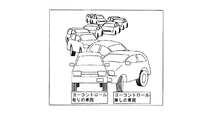
図8は、ヨー減衰制御を使用および不使用の車両の比較を図解する。ヨー減衰制御使用の車両は、ヨー減衰制御不使用の結果的に不安定であった車両と比較して優れた性能およびスタビリティを持つ。図9は、トルク偏向装置の制御に使用された関係のクラッチトルクレベルを示す。車両がオーバーステアであった場合、ELSDクラッチのみが作動する。最後に、図10は、CarSimにおける走行動画の写真を示す。 FIG. 8 illustrates a comparison of vehicles with and without yaw attenuation control. A vehicle using yaw damping control has superior performance and stability compared to a vehicle that was unstable as a result of not using yaw damping control. FIG. 9 shows the related clutch torque level used to control the torque deflection device. If the vehicle is oversteered, only the ELSD clutch is activated. Finally, FIG. 10 shows a photograph of a running movie in CarSim.
試験車両は、前駆動軸と後駆動軸の両方にイートン社製EGerodisc(登録商標)ディファレンシャルを装備した改造されたフォードF−150、ならびに、後駆動軸にイートン社製EGerodisc ll(登録商標)ディファレンシャルを装備した改造されたシボレーシルヴェラドである。目標の試験結果を得るために、関連する操作パラメータを記録するための機器を車両に装備した。dSPACEが提供するMicroAutoBoxは、Matlab/Simulinkにおける環境の試作モデルを迅速に作成する車両用リアルタイムコントローラを開発するために使用された。そのコントローラは、車両ECUと同様に車載ユニットとして設計され、サンプリングタイムは10msに設定された。dSPACEが提供する試験ソフトウェアのControlDeskは、グラフィックユーザインターフェースモード(GUI)を介してモニタおよび試験データの記録の管理に使用された。 The test vehicle includes a modified Ford F-150 equipped with Eaton's EGerodisc (R) differential on both the front and rear drive shafts, and Eaton's EGerodisc ll (R) differential on the rear drive shaft. A modified Chevrolet Silverado equipped with In order to obtain the target test results, the vehicle was equipped with equipment for recording the relevant operating parameters. MicroAutoBox from dSPACE was used to develop a real-time controller for vehicles that quickly creates prototype models of the environment in Matlab / Simulink. The controller was designed as an in-vehicle unit like the vehicle ECU, and the sampling time was set to 10 ms. The test software ControlDesk provided by dSPACE was used to manage the monitoring and recording of test data via a graphical user interface mode (GUI).
オックスフォードテクニカルソリューションズが提供するリアルタイム車両ナビゲーションシステムRT3000も試験用に使用された。RT3000は、GPSと組み合わされた6軸慣性航行システムを装備する。GPS出力は、車両のCAN通信を経由して0.5Mbits/secの通信速度でMicroAutoBoxへ伝達された。スタビリティ試験では、ホイール速度センサ、操舵角センサおよびRT3000信号(例えば、車両速度、グローバルX、グローバルY、横方向加速度、前後方向加速度、ボディスリップ角およびヨーレイト等)のセンサ情報が使用される。 The real-time vehicle navigation system RT3000 provided by Oxford Technical Solutions was also used for testing. The RT3000 is equipped with a 6-axis inertial navigation system combined with GPS. The GPS output was transmitted to MicroAutoBox via the vehicle's CAN communication at a communication speed of 0.5 Mbits / sec. In the stability test, sensor information of a wheel speed sensor, a steering angle sensor, and an RT3000 signal (for example, vehicle speed, global X, global Y, lateral acceleration, longitudinal acceleration, body slip angle, yaw rate, etc.) is used.
スタビリティ向上トラクションコントロール試験は、スプリットμでドライの滑り易い路面上で直線を使用してフルスロットルで車両を発進させて実施された。ステアリングホイール角は、目的の検証のための試験(例えば、オープンループ)の継続時間の間中ずっと0に設定された。式(23)におけるデッドバンド(しきい関数)のしきい値は、±0.5 deg/secに設定された。その設計パラメータaは、この試験のために0.5 deg/secに設定された。図11−13に示されるように、試験データは、スタビリティ向上トラクションコントロールモードで車両を発進させる間、車両スタビリティが著しく向上することを説明する。ノーマルトラクションコントロールモードを使用した単独運転の場合、車両は、路面の滑り易い部分の方へ急激にスピンアウトした。スタビリティ向上トラクションコントロールを使用した場合、車両ヨー動力学は安定し、車両は実質的に前部を真直ぐに向けた状態を維持する。最小限の好ましくないヨーは低いデッドバンドのしきい値により得られたが、車両をよりゆっくりと発進させた。しかしながら、デッドバンドのしきい値は運転者の技量に基づき調節することができる。
The stability improvement traction control test was conducted by starting the vehicle at full throttle using a straight line on a dry, slippery road with split μ. The steering wheel angle was set to 0 throughout the duration of the test for purpose verification (eg, open loop). Threshold deadband (threshold function) in equation (23) was set to ± 0.5 deg / sec. The design parameter a was set to 0.5 deg / sec for this test. As shown in FIGS. 11-13, the test data explains that vehicle stability is significantly improved while starting the vehicle in the stability-enhancing traction control mode. In the case of single operation using the normal traction control mode, the vehicle suddenly spun out toward the slippery part of the road surface. When using stability-enhancing traction control, the vehicle yaw dynamics are stable and the vehicle remains substantially pointed forward. Minimal undesirable yaw was obtained by Threshold lower deadband but was slower starting the vehicle. However, the deadband threshold can be adjusted based on the driver's skill.
例えば、ホイール速度センサのような車両センサにより決定された車両速度が、予め決定された車両速度を超えると、ヨー減衰コントローラはアクティブになる。とりわけ、スラローム操作は車両が不安定な状態を作り出す。オーバーステア挙動は、低μの表面でのスラローム運転の下で継続することができ、よって、スラローム運転は、アクティブヨーコントロールを評価する上で選択される。試験コースには固まった雪の表面を使用し、7つのコーンを約100フィート間隔で直線に配置した。そこで、運転者は、車両の速度を約50km/hまで上げてスラロームコースに進入した。 For example, the yaw attenuation controller becomes active when the vehicle speed determined by a vehicle sensor, such as a wheel speed sensor, exceeds a predetermined vehicle speed. In particular, slalom operation creates an unstable state of the vehicle. Oversteer behavior can continue under slalom operation on a low μ surface, and therefore slalom operation is selected in evaluating active yaw control. The test course used a solid snow surface and seven cones were placed in a straight line at approximately 100 feet intervals. Therefore, the driver increased the speed of the vehicle to about 50 km / h and entered the slalom course.
図14−図24を参照すると、車両ディファレンシャルのアクティブコントロールは、スラローム走行中の車両動力学を向上させることを示す。しかしながら、もし、車両が操縦限界を超えていない場合、ヨーコントロールシステムが作動しているか否かの違いを識別するのは困難である。車両が操縦限界で運転されていない場合、その性能が、運転者の技量が重大な影響を及ぼすことは注目する点である。 14-24, vehicle differential active control is shown to improve vehicle dynamics during slalom travel. However, if the vehicle does not exceed the steering limit, it is difficult to identify the difference whether the yaw control system is operating. It is worth noting that when a vehicle is not driven at the maneuver limit, its performance has a significant impact on the driver's skill.
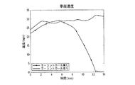
図14−図22は、ヨー減衰コントローラ54を使用する操縦限界が定速コントロールに達した場合と達していない場合との双方のスラローム操作の試験結果を図解する。ヨー減衰コントローラ54を使用する車両は、要求されるヨーレイトが発生する方向性を持続するのに対し、ヨー減衰コントローラ54を使用しない車両は、スタビリティを失い軌道を逸した。車両前後方向速度の比較は図16および図20にも示される。ヨー減衰コントローラ54を使用しない車両は、車両疾走によって反対方向の速度性能を示す。ヨー減衰コントローラ54を使用することで、オーバーステア挙動がヨー減衰が加わることを検出した場合にディファレンシャルが作動し、運転者が望ましい車両軌道を持続することを容易にする。
FIGS. 14-22 illustrate the test results of both slalom operations with and without the steering limit using the
図23および図24を参照すると、固まった雪の路面におけるオープンループ正弦波操舵走行は、ヨー減衰コントローラ54を使用するハンドリング特性を評価するために行われた。運転者は、定速制御を使用して約0.5Hzの操舵周波数で正弦波入力操舵角で車両を運転した。試験結果は、ヨー減衰コントローラ54がオーバーステア挙動を修正するコーナー中間後期からコーナー出口までを除いて車両はほとんどの期間アンダーステアだったことを示す図23および図24に図解される。
Referring to FIGS. 23 and 24, an open loop sinusoidal steering run on a solid snow road was performed to evaluate handling characteristics using the
本発明を、前述の明細書に詳細に説明したが、本発明の様々な変更および修正は本明細書を読み理解することにより当業者に明らかとなると考えられる。そのような変更および修正は、添付の請求の範囲内において、本発明に含むものとする。 Although the present invention has been described in detail in the foregoing specification, various changes and modifications of the invention will become apparent to those skilled in the art upon reading and understanding this specification. Such changes and modifications are intended to be included in the present invention within the scope of the appended claims.
Claims (2)
前記第1および第2ホイール(28,30)間にトルクを分配するように構成されるディファレンシャル装置(22)と、
第1車両運転状態において低トラクション運転状態を示す少なくとも1つの車両運転パラメータによって前記ディファレンシャル装置(22)を作動させるように構成され、さらに、低トラクション運転状態の間、実際の車両ヨーレイトと予め決定された目標の車両ヨーレイトとの差分によって第2車両運転状態にある前記ディファレンシャル装置(22)の作動を制御し、車両発進から予め決定された車両速度まで前記ディファレンシャル装置(22)の作動を制御するスタビリティ向上トラクションコントローラ(52)と、
予め設定された車両速度を超えての前記ディファレンシャル装置(22)の作動を制御するスタビリティコントローラ(54)と、
を含み、
前記トラクションコントローラ(52)は、前記低トラクション運転状態の間、前記実際の車両ヨーレイトと予め決定された目標の車両ヨーレイトとの差分によって前記ディファレンシャル装置(22)の作動を調節するように構成され、
前記トラクションコントローラ(52)は、修正された最初のディファレンシャル適用トルク信号に基づく要求されるディファレンシャル適用トルク信号によって前記ディファレンシャル装置(22)を作動させるように構成され、
前記要求されるディファレンシャル適用トルク信号は、
u :要求されるディファレンシャル適用トルク信号
utraction :最初のディファレンシャル適用トルク信号
Δr :実際の車両ヨーレイトと予め決定された目標の車両ヨーレイトとの差分
deadband :実際の車両ヨーレイトと予め決定された目標の車両ヨーレイトとの差分のしきい関数
sat :実際の車両ヨーレイトが上下限値aを超えた場合に線形近似を行うためコントローラ出力を[−a,+a]に設定する数学的関数
a :sat で使用される設計パラメータ
の関数として決定されることを特徴とする車両用コントロールシステム(50)。 A vehicle control system (50) having first and second wheels (28, 30), comprising:
A differential device (22) configured to distribute torque between the first and second wheels (28, 30);
The differential device (22) is configured to operate according to at least one vehicle operation parameter indicating a low traction operation state in the first vehicle operation state, and is further determined in advance as an actual vehicle yaw rate during the low traction operation state. The operation of the differential device (22) in the second vehicle operating state is controlled by the difference from the target vehicle yaw rate, and the operation of the differential device (22) is controlled from the start of the vehicle to a predetermined vehicle speed. Traction controller (52),
A stability controller (54) for controlling the operation of the differential device (22) beyond a preset vehicle speed;
Including
The traction controller (52) is configured to adjust the operation of the differential device (22) according to a difference between the actual vehicle yaw rate and a predetermined target vehicle yaw rate during the low traction driving state,
The traction controller (52) is configured to operate the differential device (22) with a required differential applied torque signal based on a modified initial differential applied torque signal;
The required differential application torque signal is:
u: Required differential application torque signal
u traction : first differential application torque signal Δr: difference between actual vehicle yaw rate and predetermined target vehicle yaw rate
deadband: threshold function of the difference between the actual vehicle yaw rate and a predetermined target vehicle yaw rate
sat: Mathematical function that sets the controller output to [-a, + a] to perform linear approximation when the actual vehicle yaw rate exceeds the upper and lower limits a
a: Vehicle control system (50) characterized in that it is determined as a function of the design parameters used in sat.
Applications Claiming Priority (3)
| Application Number | Priority Date | Filing Date | Title |
|---|---|---|---|
| US76504606P | 2006-02-03 | 2006-02-03 | |
| US60/765,046 | 2006-02-03 | ||
| PCT/IB2007/000242 WO2007088467A2 (en) | 2006-02-03 | 2007-02-02 | Stability-enhanced traction and yaw control using electronically controlled limited-slip differential |
Publications (2)
| Publication Number | Publication Date |
|---|---|
| JP2009525440A JP2009525440A (en) | 2009-07-09 |
| JP5246500B2 true JP5246500B2 (en) | 2013-07-24 |
Family
ID=38326276
Family Applications (1)
| Application Number | Title | Priority Date | Filing Date |
|---|---|---|---|
| JP2008552914A Expired - Fee Related JP5246500B2 (en) | 2006-02-03 | 2007-02-02 | Stability enhancement traction and yaw control used in electronically controlled limited slip differentials |
Country Status (15)
| Country | Link |
|---|---|
| US (1) | US7801657B2 (en) |
| EP (1) | EP1979189B1 (en) |
| JP (1) | JP5246500B2 (en) |
| KR (1) | KR20080092981A (en) |
| CN (1) | CN101395025B (en) |
| AT (1) | ATE507996T1 (en) |
| AU (1) | AU2007210853B2 (en) |
| BR (1) | BRPI0706922A2 (en) |
| CA (1) | CA2641897C (en) |
| DE (1) | DE602007014323D1 (en) |
| ES (1) | ES2362238T3 (en) |
| MX (1) | MX2008009971A (en) |
| PL (1) | PL1979189T3 (en) |
| RU (1) | RU2449909C2 (en) |
| WO (1) | WO2007088467A2 (en) |
Families Citing this family (46)
| Publication number | Priority date | Publication date | Assignee | Title |
|---|---|---|---|---|
| AU2007210853B2 (en) * | 2006-02-03 | 2012-03-08 | Eaton Intelligent Power Limited | Stability-enhanced traction and yaw control using electronically controlled limited-slip differential |
| WO2008054533A2 (en) * | 2006-05-09 | 2008-05-08 | Lockheed Martin Corporation | Mobility traction control system and method |
| US8589049B2 (en) | 2007-12-03 | 2013-11-19 | Lockheed Martin Corporation | GPS-based system and method for controlling vehicle characteristics based on terrain |
| US20090143937A1 (en) * | 2007-12-04 | 2009-06-04 | Lockheed Martin Corporation | GPS-based traction control system using wirelessly received weather data |
| US8145402B2 (en) * | 2007-12-05 | 2012-03-27 | Lockheed Martin Corporation | GPS-based traction control system and method using data transmitted between vehicles |
| US8229639B2 (en) * | 2009-02-17 | 2012-07-24 | Lockheed Martin Corporation | System and method for stability control |
| US8244442B2 (en) * | 2009-02-17 | 2012-08-14 | Lockheed Martin Corporation | System and method for stability control of vehicle and trailer |
| US8352120B2 (en) | 2009-02-17 | 2013-01-08 | Lockheed Martin Corporation | System and method for stability control using GPS data |
| US20100209885A1 (en) * | 2009-02-18 | 2010-08-19 | Gm Global Technology Operations, Inc. | Vehicle stability enhancement control adaptation to driving skill based on lane change maneuver |
| US9605740B2 (en) * | 2009-10-01 | 2017-03-28 | Ford Global Technologies, Llc | Control of an electronic locking differential |
| US20110269595A1 (en) | 2010-04-30 | 2011-11-03 | American Axle & Manufacturing Inc. | Control strategy for operating a locking differential |
| US8437914B2 (en) | 2010-05-18 | 2013-05-07 | Ford Global Technologies | Electric motor enhanced driveability in vehicle handling and stability control events |
| JP5257414B2 (en) * | 2010-07-09 | 2013-08-07 | 日産自動車株式会社 | Driving force distribution control device for four-wheel drive vehicle |
| US8998765B2 (en) | 2010-07-14 | 2015-04-07 | E-Aam Driveline Systems Ab | Axle assembly with torque distribution drive mechanism |
| US8663051B2 (en) | 2010-07-14 | 2014-03-04 | E-Aam Driveline Systems Ab | Axle assembly with torque distribution drive mechanism |
| JP5498887B2 (en) * | 2010-07-27 | 2014-05-21 | ナブテスコ株式会社 | Damping test method, control device, hydraulic system, and program |
| US20130231837A1 (en) * | 2012-03-02 | 2013-09-05 | GM Global Technology Operations LLC | Electronic control of a limited slip differential |
| US8831853B1 (en) | 2013-07-12 | 2014-09-09 | Andrew Wyllie Barrowman | Slip or loss of traction detector using the third derivative of rotational speed difference |
| WO2015058059A1 (en) * | 2013-10-18 | 2015-04-23 | The Florida State University Research Foundation, Inc. | Slip mitigation control for electric ground vehicles |
| US20160090005A1 (en) * | 2014-03-10 | 2016-03-31 | Dean Drako | Distributed Torque Generation System and Method of Control |
| SE539607C2 (en) * | 2014-06-24 | 2017-10-17 | Dsensed Tech Ab | A method and system for controlling the stability and response of a vehicle |
| US20160121883A1 (en) * | 2014-11-05 | 2016-05-05 | GM Global Technology Operations LLC | Front-rear torque split control for an all-wheel-drive vehicle with independent power-sources |
| JP6413953B2 (en) * | 2015-06-29 | 2018-10-31 | 株式会社デンソー | Lane departure avoidance system |
| US9784354B2 (en) | 2015-09-24 | 2017-10-10 | Ford Global Technologies, Llc | Method for controlling a limited slip differential |
| US9873426B2 (en) | 2016-06-21 | 2018-01-23 | Ford Global Technologies, Llc | System for mitigating vehicle sway |
| IT201600094657A1 (en) * | 2016-09-21 | 2018-03-21 | Same Deutz Fahr Italia S P A | VEHICLE FOR AGRICULTURAL USE WITH MEANS OF ANALYSIS VEHICLE STATUS AND DIFFERENTIAL GROUP CONTROL |
| WO2018110346A1 (en) * | 2016-12-13 | 2018-06-21 | 本田技研工業株式会社 | Torque distributor control device |
| US10066722B2 (en) | 2017-01-05 | 2018-09-04 | GM Global Technology Operations LLC | Limited slip differentials with centrifugal spring mass actuator for vehicle powertrains |
| DE112018001436T5 (en) * | 2017-04-14 | 2019-12-05 | Eaton Intelligent Power Limited | METHOD FOR COMPENSATING THE CLUTCH MOMENT IN AN ELECTRONIC BARRIER DIFFERENTIAL |
| US9958049B1 (en) | 2017-05-15 | 2018-05-01 | E-Aam Driveline Systems Ab | Electric drive module with Ravigneaux gearset |
| DE102017114494A1 (en) * | 2017-06-29 | 2019-01-03 | Thyssenkrupp Ag | Steer-by-wire steering system with torque vectoring and integrated anti-slip control |
| RU2769204C2 (en) | 2017-09-19 | 2022-03-29 | Бомбардье Рекриэйшенел Продактс Инк. | Limited slip differential control based on engine torque |
| CA3076158A1 (en) | 2017-09-19 | 2019-03-28 | Bombardier Recreational Products Inc. | Control of a limited slip differential optimized for slippery driving conditions |
| WO2019058234A1 (en) * | 2017-09-19 | 2019-03-28 | Bombardier Recreational Products Inc. | Control of a limited slip differential based on an accelerator control position |
| WO2019058227A1 (en) | 2017-09-19 | 2019-03-28 | Bombardier Recreational Products Inc. | Control of a limited slip differential based on a steering angle of a vehicle |
| US10316946B2 (en) | 2017-10-13 | 2019-06-11 | E-Aam Driveline Systems Ab | Two mode electric drive module with Ravigneaux gearset |
| US10451161B2 (en) | 2017-11-06 | 2019-10-22 | Ford Global Technologies, Llc | Electronic locking differential |
| US10501082B2 (en) * | 2017-11-06 | 2019-12-10 | Ford Global Technologies, Llc | Electronic locking differential |
| CN108177692B (en) * | 2017-12-28 | 2019-07-30 | 吉林大学 | A kind of differential power-assisted steering of electric wheel drive vehicle and stability control method for coordinating |
| DE102018101182A1 (en) * | 2018-01-19 | 2019-07-25 | Thyssenkrupp Ag | A method for avoiding flashovers of a motor vehicle by means of torque vectoring |
| US10858005B2 (en) | 2018-12-13 | 2020-12-08 | Honda Motor Co., Ltd. | Launch control |
| KR102603040B1 (en) * | 2019-05-07 | 2023-11-15 | 현대자동차주식회사 | Vehicle launch control mathod |
| CN112937579A (en) * | 2019-11-22 | 2021-06-11 | 北京宝沃汽车股份有限公司 | Vehicle, and control method and control device thereof |
| DE102020100954A1 (en) * | 2020-01-16 | 2021-07-22 | Audi Aktiengesellschaft | Power transmission system with targeted provision of drive torque |
| US11651633B2 (en) * | 2021-05-20 | 2023-05-16 | GM Global Technology Operations LLC | System and method for estimating a clutch torque of an electronic limited slip differential and tire longitudinal forces |
| KR102674698B1 (en) * | 2021-10-18 | 2024-06-13 | 경북대학교 산학협력단 | Braking System for Electric Vehicles |
Family Cites Families (70)
| Publication number | Priority date | Publication date | Assignee | Title |
|---|---|---|---|---|
| JPS6294421A (en) * | 1985-10-18 | 1987-04-30 | Fuji Heavy Ind Ltd | Rear-wheel driving apparatus for vehicle |
| JPS62214019A (en) * | 1986-03-13 | 1987-09-19 | Nissan Motor Co Ltd | Differential limitation control device for vehicle with driving wheel propulsion control device |
| US5332059A (en) * | 1991-04-26 | 1994-07-26 | Fuji Jukogyo Kabushiki Kaisha | Control system for a differential of a motor vehicle |
| US5388658A (en) * | 1991-12-02 | 1995-02-14 | Imra America, Inc. | Integrated torque and steering control system |
| DE69304144T2 (en) * | 1992-06-15 | 1997-01-09 | Mitsubishi Motors Corp | Device and method for distributing the drive torque to the right / left wheel of a motor vehicle |
| US5450919A (en) * | 1993-01-12 | 1995-09-19 | Mazda Motor Corporation | Differential action control system of a vehicle |
| US5417298A (en) * | 1993-07-07 | 1995-05-23 | Honda Giken Kohyo Kabushiki Kaisha | Torque distribution control apparatus for vehicle |
| JP3411937B2 (en) * | 1993-08-18 | 2003-06-03 | マツダ株式会社 | Vehicle control device |
| JP2981965B2 (en) * | 1993-11-29 | 1999-11-22 | 本田技研工業株式会社 | Vehicle driving force control device |
| JP3291916B2 (en) * | 1994-06-06 | 2002-06-17 | 株式会社エクォス・リサーチ | Hybrid vehicle |
| JPH07329595A (en) * | 1994-06-06 | 1995-12-19 | Nissan Diesel Motor Co Ltd | Differential limiting control device |
| JPH0848256A (en) * | 1994-08-08 | 1996-02-20 | Toyota Motor Corp | Travel control device of vehicle |
| JP3534271B2 (en) * | 1995-04-20 | 2004-06-07 | 株式会社エクォス・リサーチ | Hybrid vehicle |
| US7386372B2 (en) * | 1995-06-07 | 2008-06-10 | Automotive Technologies International, Inc. | Apparatus and method for determining presence of objects in a vehicle |
| US5648903A (en) * | 1995-07-10 | 1997-07-15 | Ford Global Technologies, Inc. | Four wheel steering control utilizing front/rear tire longitudinal slip difference |
| US6059065A (en) * | 1996-08-06 | 2000-05-09 | Denso Corporation | Driving torque control method and apparatus for a four-wheel drive vehicle |
| US5878357A (en) * | 1996-09-03 | 1999-03-02 | Ford Global Technologies, Inc. | Method and apparatus for vehicle yaw rate estimation |
| JPH10129288A (en) * | 1996-10-31 | 1998-05-19 | Isuzu Motors Ltd | Four-wheel drive vehicle |
| JPH10194001A (en) * | 1997-01-16 | 1998-07-28 | Tochigi Fuji Ind Co Ltd | Differential gear |
| JP4014016B2 (en) * | 1997-10-24 | 2007-11-28 | 富士重工業株式会社 | Differential restriction control device for four-wheel drive vehicle |
| US6289281B1 (en) * | 1997-12-12 | 2001-09-11 | Honda Giken Kogyo Kabushiki Kaisha | Integrated control system of vehicle |
| US6272418B1 (en) * | 1997-12-12 | 2001-08-07 | Honda Giken Kogyo Kabushiki Kaisha | Integrated control system of vehicle |
| DE19919969B4 (en) * | 1999-04-30 | 2006-06-14 | Daimlerchrysler Ag | Traction control method |
| DE10049567B4 (en) * | 1999-10-08 | 2017-12-14 | Toyota Jidosha Kabushiki Kaisha | Vehicle control unit for controlling a four-wheel drive motor vehicle |
| JP2001171504A (en) * | 1999-12-16 | 2001-06-26 | Nissan Motor Co Ltd | Road surface friction coefficient estimating device |
| WO2001081139A1 (en) * | 2000-04-19 | 2001-11-01 | Continental Teves Ag & Co. Ohg | Method for the online determination of values of the dynamics of vehicle movement of a motor vehicle |
| US7233236B2 (en) * | 2000-09-25 | 2007-06-19 | Ford Global Technologies, Llc | Passive wheel lift identification for an automotive vehicle using operating input torque to wheel |
| DE10056760A1 (en) * | 2000-11-16 | 2002-05-23 | Bayerische Motoren Werke Ag | Control for increasing vehicle traction with maintained stability involves continuously forming slip threshold depending on slip integral derived from wheel speed difference |
| US6453226B1 (en) * | 2001-01-25 | 2002-09-17 | Delphi Technologies, Inc. | Integrated control of active tire steer and brakes |
| JP4638065B2 (en) * | 2001-02-08 | 2011-02-23 | 富士重工業株式会社 | Control device for four-wheel drive vehicle |
| JP4019813B2 (en) * | 2001-07-12 | 2007-12-12 | 株式会社豊田中央研究所 | Physical quantity estimation device, road friction state estimation device, steering angle neutral point estimation device, and air pressure drop estimation device |
| US6766239B2 (en) * | 2001-09-07 | 2004-07-20 | Kelsey-Hayes Company | Advanced wheel slip detection using suspension system information |
| JP3808744B2 (en) * | 2001-10-11 | 2006-08-16 | 本田技研工業株式会社 | Vehicle motion control device |
| JP2003136990A (en) * | 2001-10-31 | 2003-05-14 | Toyoda Mach Works Ltd | Method for distributing driving power for vehicle and device for controlling driving power distribution |
| US6553293B1 (en) * | 2002-01-03 | 2003-04-22 | Delphi Technologies, Inc. | Rear steering control for vehicles with front and rear steering |
| US6733411B1 (en) * | 2002-01-31 | 2004-05-11 | Dana Corporation | Electronically controlled hydraulic actuator for limited slip differential assembly |
| US6618651B1 (en) * | 2002-02-25 | 2003-09-09 | Visteon Global Technologies, Inc. | Estimating vehicle velocities using linear-parameter-varying and gain varying scheduling theories |
| US6692396B1 (en) * | 2002-02-27 | 2004-02-17 | Torque-Traction Technologies, Inc. | Solenoid actuated variable pressure relief valve assembly for limited slip differential assembly |
| JP3617502B2 (en) * | 2002-04-11 | 2005-02-09 | 日産自動車株式会社 | Lane departure prevention device |
| DE60305232T2 (en) * | 2002-04-23 | 2007-03-08 | Aisin Seiki K.K., Kariya | Device for estimating the adhesion factor of a vehicle wheel |
| US6725989B1 (en) * | 2002-04-24 | 2004-04-27 | Torque-Traction Technologies, Inc. | Variably controlled torque coupling device for on-demand all-wheel drive drivetrains |
| DE60324227D1 (en) * | 2002-06-19 | 2008-12-04 | Jtekt Corp | Control method for driving force distribution and device for a vehicle with four-wheel drive |
| DE10245032A1 (en) * | 2002-09-26 | 2004-04-08 | Dr.Ing.H.C. F. Porsche Ag | Procedure for controlling driving behavior by influencing the yaw rate |
| JP3823924B2 (en) * | 2003-01-31 | 2006-09-20 | 日産自動車株式会社 | Vehicle behavior control device |
| US6752233B1 (en) * | 2003-02-11 | 2004-06-22 | General Motors Corporation | Selectable overspeed secondary drive module |
| US7175557B2 (en) * | 2003-02-21 | 2007-02-13 | Magna Powertrain Usa, Inc. | Torque vectoring device having an electric motor/brake actuator and friction clutch |
| US7211019B2 (en) * | 2003-02-21 | 2007-05-01 | Magna Powertrain Usa, Inc. | Torque vectoring drive mechanism having a power sharing control system |
| US6830122B2 (en) * | 2003-02-26 | 2004-12-14 | Dana Corporation | Vehicle yaw management system with driveline torque control |
| US6909959B2 (en) * | 2003-03-07 | 2005-06-21 | Stephen James Hallowell | Torque distribution systems and methods for wheeled vehicles |
| DE10316645A1 (en) | 2003-04-11 | 2004-10-28 | Robert Bosch Gmbh | Device for operating a gas sensor |
| JP4258265B2 (en) | 2003-04-30 | 2009-04-30 | 日産自動車株式会社 | Vehicle behavior control device |
| DE10333654B4 (en) * | 2003-07-24 | 2005-09-29 | Bayerische Motoren Werke Ag | Control device for an at least temporarily four-wheel drive motor vehicle |
| US7007763B2 (en) * | 2003-09-19 | 2006-03-07 | Borgwarner Inc. | Control system for interactive driveline and vehicle control |
| JP2005125986A (en) * | 2003-10-27 | 2005-05-19 | Fuji Heavy Ind Ltd | Vehicle control device and vehicle control method |
| JP4496759B2 (en) * | 2003-10-29 | 2010-07-07 | 日産自動車株式会社 | Lane departure prevention device |
| JP4496760B2 (en) * | 2003-10-29 | 2010-07-07 | 日産自動車株式会社 | Lane departure prevention device |
| US7212901B2 (en) * | 2003-10-29 | 2007-05-01 | Nissan Motor Co., Ltd. | Lane departure prevention apparatus |
| US7200478B2 (en) * | 2003-10-31 | 2007-04-03 | Nissan Motor Co., Ltd. | Lane departure prevention apparatus |
| US7444224B2 (en) * | 2003-11-14 | 2008-10-28 | Nissan Motor Co., Ltd. | Lane departure prevention apparatus |
| US7004870B2 (en) * | 2004-02-25 | 2006-02-28 | Dana Corporation | Integrated torque and roll control system |
| US7229139B2 (en) * | 2004-03-18 | 2007-06-12 | Ford Global Technologies, Llc | Control system for brake-steer assisted parking and method therefor |
| US7044880B2 (en) * | 2004-05-20 | 2006-05-16 | Magna Powertrain, Inc. | Torque distributing differential assembly |
| US7059990B2 (en) * | 2004-05-25 | 2006-06-13 | Magna Powertrain, Inc. | Torque vectoring drive axle assembly |
| US7004876B2 (en) * | 2004-05-27 | 2006-02-28 | Magna Powertrain, Inc. | Torque vectoring limited slip differential assembly |
| JP4289243B2 (en) * | 2004-07-16 | 2009-07-01 | 三菱自動車工業株式会社 | Driving force control device for left and right wheels for vehicle |
| JP4417203B2 (en) * | 2004-08-23 | 2010-02-17 | 本田技研工業株式会社 | Driving force control method for four-wheel drive vehicle |
| US7640081B2 (en) * | 2004-10-01 | 2009-12-29 | Ford Global Technologies, Llc | Roll stability control using four-wheel drive |
| JP4114657B2 (en) * | 2004-10-25 | 2008-07-09 | 三菱自動車工業株式会社 | Vehicle turning behavior control device |
| AU2007210853B2 (en) * | 2006-02-03 | 2012-03-08 | Eaton Intelligent Power Limited | Stability-enhanced traction and yaw control using electronically controlled limited-slip differential |
| JP4969936B2 (en) * | 2006-07-28 | 2012-07-04 | 富士重工業株式会社 | Vehicle driving force distribution control device |
-
2007
- 2007-02-02 AU AU2007210853A patent/AU2007210853B2/en not_active Ceased
- 2007-02-02 EP EP07705516A patent/EP1979189B1/en active Active
- 2007-02-02 AT AT07705516T patent/ATE507996T1/en active
- 2007-02-02 CN CN2007800077482A patent/CN101395025B/en active Active
- 2007-02-02 DE DE602007014323T patent/DE602007014323D1/en active Active
- 2007-02-02 US US11/701,851 patent/US7801657B2/en active Active
- 2007-02-02 CA CA2641897A patent/CA2641897C/en not_active Expired - Fee Related
- 2007-02-02 MX MX2008009971A patent/MX2008009971A/en active IP Right Grant
- 2007-02-02 WO PCT/IB2007/000242 patent/WO2007088467A2/en active Application Filing
- 2007-02-02 RU RU2008135703/11A patent/RU2449909C2/en not_active IP Right Cessation
- 2007-02-02 JP JP2008552914A patent/JP5246500B2/en not_active Expired - Fee Related
- 2007-02-02 PL PL07705516T patent/PL1979189T3/en unknown
- 2007-02-02 KR KR1020087021572A patent/KR20080092981A/en not_active Application Discontinuation
- 2007-02-02 ES ES07705516T patent/ES2362238T3/en active Active
- 2007-02-02 BR BRPI0706922-7A patent/BRPI0706922A2/en not_active IP Right Cessation
Also Published As
| Publication number | Publication date |
|---|---|
| BRPI0706922A2 (en) | 2011-04-12 |
| JP2009525440A (en) | 2009-07-09 |
| WO2007088467A3 (en) | 2007-11-22 |
| US7801657B2 (en) | 2010-09-21 |
| US20070184929A1 (en) | 2007-08-09 |
| CA2641897A1 (en) | 2007-08-09 |
| ES2362238T3 (en) | 2011-06-30 |
| MX2008009971A (en) | 2008-10-03 |
| DE602007014323D1 (en) | 2011-06-16 |
| RU2449909C2 (en) | 2012-05-10 |
| CA2641897C (en) | 2012-11-27 |
| AU2007210853B2 (en) | 2012-03-08 |
| RU2008135703A (en) | 2010-03-10 |
| WO2007088467A2 (en) | 2007-08-09 |
| PL1979189T3 (en) | 2011-09-30 |
| KR20080092981A (en) | 2008-10-16 |
| EP1979189B1 (en) | 2011-05-04 |
| ATE507996T1 (en) | 2011-05-15 |
| AU2007210853A1 (en) | 2007-08-09 |
| EP1979189A2 (en) | 2008-10-15 |
| CN101395025B (en) | 2012-04-11 |
| CN101395025A (en) | 2009-03-25 |
Similar Documents
| Publication | Publication Date | Title |
|---|---|---|
| JP5246500B2 (en) | Stability enhancement traction and yaw control used in electronically controlled limited slip differentials | |
| JP5120657B2 (en) | Stability-enhanced traction control with electronically controlled center coupler | |
| US9950703B2 (en) | Vehicle with independently driven multiple axes, and controller which independently drives multiple axles | |
| DE102005046776B4 (en) | Roll stability control using four-wheel drive | |
| JP5039451B2 (en) | Driving torque distribution method | |
| US7873459B2 (en) | Load transfer adaptive traction control system | |
| DE102011076589A1 (en) | VEHICLE STEERING AND STABILITY CONTROL BY AN INDEPENDENT WHEEL TORQUE CONTROL | |
| US10029677B2 (en) | Vehicle control system and method | |
| JP2022189780A (en) | Control method of road vehicle having independent engine acting on wheels of same axle and relevant road vehicle | |
| US8204669B2 (en) | Method and device for regulating the driving dynamics of a vehicle | |
| Piyabongkarn et al. | Stability-enhanced traction and yaw control using electronic limited slip differential | |
| US20120046842A1 (en) | Method for producing a differential torque acting on the vehicle wheels of a vehicle | |
| Park et al. | Dana torque vectoring differential dynamic trak™ | |
| Sill et al. | A saturation-balancing control method for enhancing dynamic vehicle stability | |
| JP4358070B2 (en) | Body slip angle estimation method | |
| KR20070016160A (en) | Method for compensating a dynamic axle load transfer | |
| Duringhof et al. | Development and Vehicle Integration of XWD Driveline Technology |
Legal Events
| Date | Code | Title | Description |
|---|---|---|---|
| A621 | Written request for application examination |
Free format text: JAPANESE INTERMEDIATE CODE: A621 Effective date: 20090924 |
|
| A131 | Notification of reasons for refusal |
Free format text: JAPANESE INTERMEDIATE CODE: A131 Effective date: 20120328 |
|
| A521 | Request for written amendment filed |
Free format text: JAPANESE INTERMEDIATE CODE: A523 Effective date: 20120627 |
|
| A131 | Notification of reasons for refusal |
Free format text: JAPANESE INTERMEDIATE CODE: A131 Effective date: 20120808 |
|
| A521 | Request for written amendment filed |
Free format text: JAPANESE INTERMEDIATE CODE: A523 Effective date: 20121018 |
|
| TRDD | Decision of grant or rejection written | ||
| A01 | Written decision to grant a patent or to grant a registration (utility model) |
Free format text: JAPANESE INTERMEDIATE CODE: A01 Effective date: 20130227 |
|
| A61 | First payment of annual fees (during grant procedure) |
Free format text: JAPANESE INTERMEDIATE CODE: A61 Effective date: 20130327 |
|
| R150 | Certificate of patent or registration of utility model |
Free format text: JAPANESE INTERMEDIATE CODE: R150 |
|
| FPAY | Renewal fee payment (event date is renewal date of database) |
Free format text: PAYMENT UNTIL: 20160419 Year of fee payment: 3 |
|
| LAPS | Cancellation because of no payment of annual fees |