JP5244461B2 - Chemical analyzer and analysis chip - Google Patents

Chemical analyzer and analysis chip Download PDF

Info

Publication number
JP5244461B2
JP5244461B2 JP2008140583A JP2008140583A JP5244461B2 JP 5244461 B2 JP5244461 B2 JP 5244461B2 JP 2008140583 A JP2008140583 A JP 2008140583A JP 2008140583 A JP2008140583 A JP 2008140583A JP 5244461 B2 JP5244461 B2 JP 5244461B2
Authority
JP
Japan
Prior art keywords
opening
reaction chamber
storage tank
pressure
test sample
Prior art date
Legal status (The legal status is an assumption and is not a legal conclusion. Google has not performed a legal analysis and makes no representation as to the accuracy of the status listed.)
Active
Application number
JP2008140583A
Other languages
Japanese (ja)
Other versions
JP2009288053A (en
Inventor
昌造 橋本
Current Assignee (The listed assignees may be inaccurate. Google has not performed a legal analysis and makes no representation or warranty as to the accuracy of the list.)
Toshiba Corp
Canon Medical Systems Corp
Original Assignee
Toshiba Corp
Toshiba Medical Systems Corp
Priority date (The priority date is an assumption and is not a legal conclusion. Google has not performed a legal analysis and makes no representation as to the accuracy of the date listed.)
Filing date
Publication date
Application filed by Toshiba Corp, Toshiba Medical Systems Corp filed Critical Toshiba Corp
Priority to JP2008140583A priority Critical patent/JP5244461B2/en
Publication of JP2009288053A publication Critical patent/JP2009288053A/en
Application granted granted Critical
Publication of JP5244461B2 publication Critical patent/JP5244461B2/en
Active legal-status Critical Current
Anticipated expiration legal-status Critical

Links

Images

Description

本発明は、液体に含まれている成分を分析する化学分析装置及び分析チップに係り、特に微量の血液や尿等の生体試料に含まれる成分を簡便に分析することができる化学分析装置及び分析チップに関する。   The present invention relates to a chemical analysis device and an analysis chip for analyzing components contained in a liquid, and in particular, a chemical analysis device and an analysis capable of easily analyzing components contained in a biological sample such as a small amount of blood or urine. Regarding chips.

化学分析装置は、被検体から採取された血液や尿などの被検試料と各検査項目に該当する試薬の混合液を、化学反応によって生ずる色調などの変化を光の透過量を測定することにより、被検試料中の様々な成分の濃度や酵素活性を求める。また、被検試料に含まれる検査項目の成分に選択的に応答するイオンセンサや酵素センサ等のセンサを用いて測定することにより、被検試料中の様々な成分の濃度を求める。   A chemical analyzer measures the amount of light transmitted through a mixture of a test sample such as blood or urine collected from a sample and a reagent corresponding to each test item, and changes in color tone or the like caused by a chemical reaction. Determine the concentration and enzyme activity of various components in the test sample. Further, the concentration of various components in the test sample is obtained by measurement using a sensor such as an ion sensor or an enzyme sensor that selectively responds to the test item component contained in the test sample.

近年、省スペースで、簡便に検査を行うことができる分析装置が知られている(例えば、特許文献1参照。)。この装置は、液体が充填された複数の液体槽、液体槽に連結された流路、及び液体槽の開口部を覆う隔壁を備えたチップ、チップ内の液体を送液させる送液装置、及び送液した液体を測定する光学的検出装置を備えている。
特開2004−226207号公報
2. Description of the Related Art In recent years, analyzers that are space-saving and can be simply inspected are known (see, for example, Patent Document 1). The apparatus includes a plurality of liquid tanks filled with a liquid, a channel connected to the liquid tank, a chip including a partition that covers an opening of the liquid tank, a liquid feeding device that feeds the liquid in the chip, and An optical detection device for measuring the supplied liquid is provided.
JP 2004-226207 A

しかしながら、特許文献1によれば、送液装置は、圧力発生手段、この圧力発生手段により発生した圧力を伝達する非圧縮性媒質、及びこの非圧縮性媒質を密封する容器とダイアフラム部材により構成されるため大型化する問題がある。   However, according to Patent Document 1, the liquid feeding device includes pressure generating means, an incompressible medium that transmits the pressure generated by the pressure generating means, and a container and a diaphragm member that seal the incompressible medium. Therefore, there is a problem of increasing the size.

本発明は、上記問題点を解決するためになされたもので、液体を送液する送液機構の小型化が可能な化学分析装置及び分析チップを提供することを目的とする。   The present invention has been made to solve the above problems, and an object thereof is to provide a chemical analysis apparatus and an analysis chip capable of downsizing a liquid feeding mechanism for feeding a liquid.

上記問題を解決するために、請求項1に係る本発明の化学分析装置は、分析チップに収容された被検試料及び試薬の混合液を測定する化学分析装置において、前記分析チップは、基板上に前記被検試料を注入するための開口部を有する収容槽と、前記収容槽と連通可能に前記基板内に配置され、前記収容槽内に注入された被検試料及び第1試薬の混合液である第1の混合液を収容するための第1の反応室と、前記基板内に配置され、前記第1の反応室と連通可能に大気圧よりも低い圧力の気体が封入された第1の圧力室と前記収容槽内と前記第1の圧力室の連通を開閉する開閉手段とを備え、前記開閉手段を開いて前記収容槽内の被検試料を前記第1の反応室内へ送液した後、前記開閉手段を閉じるようにしたことを特徴とする。 In order to solve the above problem, the chemical analyzer of the present invention according to claim 1 is a chemical analyzer for measuring a mixed solution of a test sample and a reagent contained in an analysis chip, wherein the analysis chip is on a substrate. A storage tank having an opening for injecting the test sample into the test chamber, and a liquid mixture of the test sample and the first reagent, which is disposed in the substrate so as to communicate with the storage tank and is injected into the storage tank A first reaction chamber for containing a first liquid mixture, and a first reaction chamber disposed in the substrate, in which a gas having a pressure lower than atmospheric pressure is enclosed so as to communicate with the first reaction chamber. Open / close means for opening / closing communication between the pressure chamber and the storage tank and the first pressure chamber, and opening the open / close means to feed the test sample in the storage tank into the first reaction chamber. Then, the opening / closing means is closed .

また、請求項7に係る本発明の化学分析装置は、分析チップに収容された被検試料及び試薬の混合液を測定する化学分析装置において、前記分析チップは、基板上に前記被検試料を注入するための閉塞可能な開口部を有する収容槽と、前記基板の外部及び前記収容槽と連通可能に前記基板内に配置され、前記収容槽内に注入された被検試料及び前記試薬の混合液を収容するための反応室と、前記基板内に配置され、前記収容槽と連通可能に大気圧よりも高い圧力の気体が封入された圧力室と、前記反応室と前記第1の圧力室の連通を開閉する開閉手段とを備え、前記開閉手段を開いて前記収容槽内の被検試料を前記第1の反応室内へ送液した後、前記開閉手段を閉じるようにしたことを特徴とする。 The chemical analyzer of the present invention according to claim 7 is a chemical analyzer for measuring a mixed solution of a test sample and a reagent accommodated in an analysis chip, wherein the analysis chip places the test sample on a substrate. A storage tank having an occluding opening for injection, and a mixture of a test sample and the reagent, which are arranged in the substrate so as to communicate with the outside of the substrate and the storage tank, and are injected into the storage tank A reaction chamber for storing a liquid, a pressure chamber disposed in the substrate, and filled with a gas having a pressure higher than atmospheric pressure so as to communicate with the storage tank, the reaction chamber, and the first pressure chamber And opening / closing means for opening and closing the communication, and opening and closing the opening / closing means to feed the test sample in the storage tank into the first reaction chamber, and then closing the opening / closing means. To do.

更に、請求項9に係る本発明の化学分析装置は、分析チップに収容された被検試料及び試薬の混合液を測定する化学分析装置において、前記分析チップは、基板上に前記被検試料を注入するための閉塞可能な開口部を有する収容槽と、前記基板の外部及び前記収容槽と連通可能に前記基板内に配置され、前記収容槽内に注入された被検試料及び前記試薬の混合液を収容するための反応室と、前記基板内に配置され、前記収容槽と連通する大気圧の気体が収容された圧力室と、前記圧力室内を加熱する加熱手段とを備え、前記加熱手段による前記圧力室内の加熱による前記気体の熱膨張により前記開口部が閉塞された前記収容槽内を加圧して、前記収容槽内の被検試料を前記反応室内へ送液するようにしたことを特徴とする。 Furthermore, the chemical analyzer of the present invention according to claim 9 is a chemical analyzer for measuring a mixed solution of a test sample and a reagent accommodated in an analysis chip, wherein the analysis chip places the test sample on a substrate. A storage tank having an occluding opening for injection, and a mixture of a test sample and the reagent, which are arranged in the substrate so as to communicate with the outside of the substrate and the storage tank, and are injected into the storage tank A reaction chamber for storing a liquid, a pressure chamber disposed in the substrate and containing an atmospheric gas communicating with the storage tank, and a heating unit for heating the pressure chamber, the heating unit The inside of the storage tank in which the opening is closed by the thermal expansion of the gas due to the heating in the pressure chamber is pressurized so that the test sample in the storage tank is fed into the reaction chamber. Features.

そして、請求項12に係る本発明の分析チップは、基板上に被検試料を注入するための開口部を有する収容槽と、前記収容槽と連通可能に前記基板内に配置され、前記収容槽内に注入された被検試料及び試薬の混合液を収容するための反応室と、前記基板内に配置され、前記反応室と連通可能に大気圧よりも低い圧力の気体が封入された圧力室と、前記収容槽内と前記第1の圧力室の連通を開閉する開閉手段とを備え、前記開閉手段を開いて前記収容槽内の被検試料を前記第1の反応室内へ送液した後、前記開閉手段を閉じるようにしたことを特徴とする。 An analysis chip according to the twelfth aspect of the present invention includes a storage tank having an opening for injecting a test sample onto the substrate, and is disposed in the substrate so as to communicate with the storage tank. A reaction chamber for containing a mixed solution of a test sample and a reagent injected into the chamber, and a pressure chamber disposed in the substrate and sealed with a gas having a pressure lower than atmospheric pressure so as to communicate with the reaction chamber And an opening / closing means for opening / closing communication between the inside of the storage tank and the first pressure chamber, and after opening the opening / closing means, the test sample in the storage tank is fed into the first reaction chamber. The opening / closing means is closed .

また、請求項13に係る本発明の分析チップは、基板上に被検試料を注入するための閉塞可能な開口部を有する収容槽と、前記基板の外部及び前記収容槽と連通可能に前記基板内に配置され、前記収容槽内に注入された被検試料及び試薬の混合液を収容するための反応室と、前記基板内に配置され、前記収容槽と連通可能に大気圧よりも高い圧力の気体が封入された圧力室と、前記反応室と前記第1の圧力室の連通を開閉する開閉手段とを備え、前記開閉手段を開いて前記収容槽内の被検試料を前記第1の反応室内へ送液した後、前記開閉手段を閉じるようにしたことを特徴とする。 According to a thirteenth aspect of the present invention, there is provided an analysis chip according to the present invention, comprising: a storage tank having a closable opening for injecting a test sample onto a substrate; A reaction chamber for storing a sample liquid and a reagent mixture injected into the storage tank, and a pressure higher than atmospheric pressure so as to communicate with the storage tank. A pressure chamber filled with the gas, and an opening / closing means for opening / closing communication between the reaction chamber and the first pressure chamber, and the test sample in the storage tank is opened by opening the opening / closing means. After the liquid is fed into the reaction chamber, the opening / closing means is closed .

更に、請求項14に係る本発明の分析チップは、基板上に被検試料を注入するための閉塞可能な開口部を有する収容槽と、前記基板の外部及び前記収容槽と連通可能に前記基板内に配置され、前記収容槽内に注入された被検試料及び試薬の混合液を収容するための反応室と、前記基板内に配置され、前記収容槽と連通する大気圧の気体を収容した圧力室と、前記圧力室内を加熱する加熱手段とを備え、前記加熱手段による前記圧力室内の加熱による前記気体の熱膨張により前記開口部が閉塞された前記収容槽内を加圧して、前記収容槽内の被検試料を前記反応室内へ送液するようにしたことを特徴とする。 Furthermore, the analysis chip according to the fourteenth aspect of the present invention includes a storage tank having a closable opening for injecting a test sample onto the substrate, and the substrate that can communicate with the outside of the substrate and the storage tank. A reaction chamber for accommodating a sample liquid and a reagent mixture injected into the storage tank, and a gas at atmospheric pressure which is disposed in the substrate and communicates with the storage tank. A pressure chamber; and a heating unit that heats the pressure chamber, and pressurizes the inside of the storage tank in which the opening is closed by thermal expansion of the gas due to heating of the pressure chamber by the heating unit, and The test sample in the tank is fed into the reaction chamber .

本発明によれば、分析チップ内に送液するための気体を収容した圧力室を設け、この圧力室内の気体の膨張又は収縮を利用して被検試料を送液することにより、送液用ポンプが不要となり小型化を図ることができる。   According to the present invention, a pressure chamber containing a gas to be fed into the analysis chip is provided, and the test sample is fed by utilizing the expansion or contraction of the gas in the pressure chamber. A pump is not required and the size can be reduced.

以下、本発明の実施例を、図面を参照して説明する。   Embodiments of the present invention will be described below with reference to the drawings.

本発明に係る化学分析装置の実施例1を、図1乃至図14を参照して説明する。
図1は、実施例1に係る化学分析装置の構成を示したブロック図である。この化学分析装置100は、被検試料と試薬を混合して各検査項目を測定するための分析チップ1と、この分析チップ1の測定により得られた信号を処理して分析データを生成する装置本体10とを備えている。
A first embodiment of a chemical analyzer according to the present invention will be described with reference to FIGS.
FIG. 1 is a block diagram illustrating the configuration of the chemical analyzer according to the first embodiment. This chemical analysis apparatus 100 is an apparatus for generating analysis data by processing a signal obtained by measurement of the analysis chip 1 by mixing a test sample and a reagent and measuring each inspection item, and processing signals obtained by the measurement of the analysis chip 1 And a main body 10.

分析チップ1は、各検査項目の測定方法に応じて、光学的に測定する検査項目の試薬が1試薬系である場合の第1試薬を収容した第1の分析チップ2、光学的に測定する検査項目の試薬が2試薬系である場合の第1及び第2試薬を収容した第2の分析チップ3、及び電気化学的に測定する検査項目である場合の第1試薬を収容した第3の分析チップ4等により構成される。   The analysis chip 1 optically measures the first analysis chip 2 containing the first reagent when the reagent of the test item to be optically measured is a single reagent system, according to the measurement method of each test item. The second analysis chip 3 containing the first and second reagents when the test item reagent is a two-reagent system, and the third analysis chamber containing the first reagent when the test item is an electrochemical measurement item It is comprised by the analysis chip 4 grade | etc.,.

装置本体10は、化学分析装置100の操作者が容易に運ぶことができるサイズであり、着脱可能な分析チップ1を保持するインターフェース部11と、分析チップ1の各ユニットを制御する液体制御部7と、分析チップ1を用いた測定で得られた信号を検出する検出部8と、検出部8で検出された検出信号から分析データを生成するデータ処理部9と、データ処理部9で生成された分析データなどを保存する記憶部12とを備えている。   The apparatus main body 10 has a size that can be easily carried by an operator of the chemical analysis apparatus 100, and includes an interface unit 11 that holds the removable analysis chip 1 and a liquid control unit 7 that controls each unit of the analysis chip 1. A detection unit 8 that detects a signal obtained by measurement using the analysis chip 1, a data processing unit 9 that generates analysis data from the detection signal detected by the detection unit 8, and a data processing unit 9 And a storage unit 12 for storing analysis data and the like.

また、データ処理部9で生成された分析データを出力する出力部13と、各種コマンド信号などを入力する操作部14と、操作部14からの入力情報に基づいて液体制御部7、検出部8、データ処理部9、記憶部12、及び出力部13の制御やシステム全体の制御を統括して行うシステム制御部15とを備えている。   Further, an output unit 13 that outputs analysis data generated by the data processing unit 9, an operation unit 14 that inputs various command signals and the like, and a liquid control unit 7 and a detection unit 8 based on input information from the operation unit 14. , A data processing unit 9, a storage unit 12, and an output unit 13 and a system control unit 15 that performs overall control of the system.

インターフェース部11は、開口部111を有し、この開口部111への挿入により、装置本体10に着脱自在に装着された分析チップ1を保持する。   The interface unit 11 has an opening 111, and holds the analysis chip 1 detachably attached to the apparatus main body 10 by being inserted into the opening 111.

液体制御部7は、インターフェース部11に保持された分析チップ1の近傍に配置され、分析チップ1の各ユニットを駆動して分析チップ1内の被検試料等を送液する送液機構71と、被検試料と試薬の混合液を撹拌する撹拌機構72と、送液機構71及び撹拌機構72を制御する制御部73とを備えている。   The liquid control unit 7 is disposed in the vicinity of the analysis chip 1 held by the interface unit 11, and drives a unit of the analysis chip 1 to send a test sample or the like in the analysis chip 1. , A stirring mechanism 72 for stirring the mixed solution of the test sample and the reagent, and a liquid feeding mechanism 71 and a control unit 73 for controlling the stirring mechanism 72 are provided.

検出部8は、インターフェース部11に保持された分析チップ1の各第1及び第2の分析チップ2,3に係合する第1の検出部81、及び第3の分析チップ4に係合する第2の検出部82を備えている。第1の検出部81は、例えば半導体レーザや発光ダイオード等の光源、及びこの光源からの光を検出するフォトダイオード等の受光素子を有する。そして、各第1及び第2の分析チップ2,3内の混合液に光を照射し、その混合液内を透過した光を検出して電気信号に変換する。更にその電気信号を増幅してデータ処理部9へ出力する。また、各第1及び第2の分析チップ2,3内における被検試料等の検出信号をシステム制御部15へ出力する。   The detection unit 8 is engaged with the first detection unit 81 and the third analysis chip 4 that are engaged with the first and second analysis chips 2 and 3 of the analysis chip 1 held by the interface unit 11. A second detection unit 82 is provided. The first detection unit 81 includes a light source such as a semiconductor laser or a light emitting diode, and a light receiving element such as a photodiode that detects light from the light source. Then, the mixed liquid in each of the first and second analysis chips 2 and 3 is irradiated with light, and the light transmitted through the mixed liquid is detected and converted into an electric signal. Further, the electric signal is amplified and output to the data processing unit 9. In addition, detection signals such as a test sample in each of the first and second analysis chips 2 and 3 are output to the system control unit 15.

第2の検出部82は、第3の分析チップ4内の混合液の測定により検出された検出信号を増幅する。そして増幅した信号をデータ処理部9へ出力する。また、第3の分析チップ4内における被検試料の検出信号をシステム制御部15へ出力する。   The second detection unit 82 amplifies the detection signal detected by measuring the liquid mixture in the third analysis chip 4. Then, the amplified signal is output to the data processing unit 9. Further, the detection signal of the test sample in the third analysis chip 4 is output to the system control unit 15.

データ処理部9は、検出部8の各第1及び第2の検出部81,82から出力された信号をデジタル信号に変換する収集部91と、収集部91からの信号に基づいて被検試料に含まれる各検査項目成分の分析データを生成する処理部92とを備えている。処理部92は、収集部91から出力された信号に対応する各検査項目のキャリブレーションテーブルを記憶部12から読み出した後、このキャリブレーションテーブルを用いて被検試料に含まれる各検査項目成分の濃度値や酵素活性値等の分析データを生成する。そして、生成した分析データを記憶部12に保存すると共に出力部13に出力する。   The data processing unit 9 includes a collection unit 91 that converts the signals output from the first and second detection units 81 and 82 of the detection unit 8 into digital signals, and a test sample based on the signal from the collection unit 91. And a processing unit 92 that generates analysis data of each inspection item component included in the test item component. The processing unit 92 reads out the calibration table of each inspection item corresponding to the signal output from the collection unit 91 from the storage unit 12, and then uses this calibration table to set each inspection item component included in the test sample. Analytical data such as concentration values and enzyme activity values are generated. The generated analysis data is stored in the storage unit 12 and output to the output unit 13.

記憶部12は、記憶回路を備え、操作部14から入力された入力情報やデータ処理部9の処理部92から出力された分析データ等を保存する。また、分析データの生成に用いられるキャリブレーションテーブルなどを保存している。   The storage unit 12 includes a storage circuit, and stores input information input from the operation unit 14, analysis data output from the processing unit 92 of the data processing unit 9, and the like. In addition, a calibration table used for generating analysis data is stored.

出力部13は、液晶パネル等を有し、データ処理部9の処理部92から出力された分析データを表示する。なお、前述した表示以外にも、表示灯による点灯を利用した視覚伝達手段、音声による聴覚を利用した聴覚伝達手段によっても伝達するようにしてもよい。更には、それら複数の手段を併用するようにしてもよい。   The output unit 13 includes a liquid crystal panel and displays analysis data output from the processing unit 92 of the data processing unit 9. In addition to the above-described display, it may be transmitted by visual transmission means using lighting by an indicator lamp, or auditory transmission means using auditory sound. Furthermore, you may make it use these several means together.

操作部14は、操作パネル上にボタンなどの入力デバイスを備え、被検体の情報の入力、分析チップ1に収容された被検試料の測定操作、記憶部12に保存されている様々な分析データの出力操作等を行う。   The operation unit 14 includes an input device such as a button on the operation panel. The operation unit 14 inputs information about the subject, performs a measurement operation on the test sample stored in the analysis chip 1, and various analysis data stored in the storage unit 12. The output operation etc. are performed.

以下、分析チップ1の各第1乃至第3の分析チップ2,3,4の構成の詳細、及び各第1乃至第3の分析チップ2,3,4を用いた化学分析装置100の動作の一例を説明する。
先ず、図1乃至図7を参照して、分析チップ1の第1の分析チップ2の構成及び第1の分析チップ2を用いた化学分析装置100の動作を説明する。図2は、第1の分析チップ2の構成を示すブロック図である。図3は、第1の分析チップ2の構造を示す図である。図4は、第1の分析チップ2を用いた化学分析装置100の動作を示すフローチャートである。図5は、第1の分析チップ2内における被検試料の送液を説明するための図である。図6は、第1の分析チップ2及び装置本体10の外観を示す図である。図7は、第1の分析チップ2の変形例を示す断面図である。
Hereinafter, details of the configuration of each of the first to third analysis chips 2, 3, 4 of the analysis chip 1 and the operation of the chemical analyzer 100 using each of the first to third analysis chips 2, 3, 4 are described. An example will be described.
First, the configuration of the first analysis chip 2 of the analysis chip 1 and the operation of the chemical analysis apparatus 100 using the first analysis chip 2 will be described with reference to FIGS. FIG. 2 is a block diagram showing the configuration of the first analysis chip 2. FIG. 3 is a diagram showing the structure of the first analysis chip 2. FIG. 4 is a flowchart showing the operation of the chemical analysis apparatus 100 using the first analysis chip 2. FIG. 5 is a diagram for explaining the liquid feeding of the test sample in the first analysis chip 2. FIG. 6 is a diagram showing the external appearance of the first analysis chip 2 and the apparatus main body 10. FIG. 7 is a cross-sectional view showing a modified example of the first analysis chip 2.

図2において、第1の分析チップ2は、注入された被検試料を収容する収容槽22、この収容槽22と第1の反応流路24で連通している第1の反応室23、第1の反応室23と第1の圧力流路26で連通している第1の圧力室25、第1の反応流路24を開閉する第1のバルブ27、第1の圧力流路26を開閉する第2のバルブ28、及び収容槽22から第1の反応室23を介して第1の圧力流路26へ流入した被検試料を検出する第1の検出器29の各ユニットを備えている。   In FIG. 2, the first analysis chip 2 includes a storage tank 22 that stores an injected test sample, a first reaction chamber 23 that communicates with the storage tank 22 through a first reaction channel 24, A first pressure chamber 25 communicating with one reaction chamber 23 by a first pressure channel 26, a first valve 27 for opening / closing the first reaction channel 24, and opening / closing the first pressure channel 26 Each of the first valve 29 and the first detector 29 for detecting the test sample flowing into the first pressure channel 26 from the storage tank 22 through the first reaction chamber 23. .

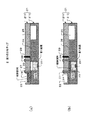
図3(a)は、第1の分析チップ2の上面図であり、図3(b)は図3(a)に示した第1の分析チップ2のA−A線における断面図である。この第1の分析チップ2の各ユニットは、ガラス、シリコン、プラスチック、セラミックス等の材料を用いて微細加工することにより形成された第1の基板211及びこの第1の基板211の下面に上面が接合された第2の基板212により構成される基板21の内外に配置される。   3A is a top view of the first analysis chip 2, and FIG. 3B is a cross-sectional view taken along the line AA of the first analysis chip 2 shown in FIG. 3A. Each unit of the first analysis chip 2 has a first substrate 211 formed by microfabrication using a material such as glass, silicon, plastic, ceramics, and the upper surface of the lower surface of the first substrate 211. Arranged inside and outside the substrate 21 constituted by the bonded second substrate 212.

収容槽22は、基板21の上面の一端部近傍に配置された開口部を有し、その開口部から注入された被検試料を収容する。   The storage tank 22 has an opening disposed in the vicinity of one end portion of the upper surface of the substrate 21 and stores a test sample injected from the opening.

第1の反応室23は、基板21内の収容槽22よりも他端部側に配置され、1試薬系の各検査項目に応じた所定量の第1試薬、及びこの第1試薬と被検試料の混合液(第1の混合液)を撹拌するための第1撹拌子231を収容している。また、第1の反応室23内の互いに対向する側面を形成している基板21の第2の基板212の両側壁を貫通する2つの貫通孔が、装置本体10における検出部8の第1の検出部81からの光を透過する2つの透過材232で閉塞されている。   The first reaction chamber 23 is disposed on the other end side of the storage tank 22 in the substrate 21, and a predetermined amount of the first reagent corresponding to each test item of the one reagent system, and the first reagent and the test sample A first stirrer 231 for stirring the sample mixed solution (first mixed solution) is accommodated. In addition, two through holes penetrating both side walls of the second substrate 212 of the substrate 21 forming mutually opposing side surfaces in the first reaction chamber 23 are the first of the detection unit 8 in the apparatus main body 10. The light is blocked by two transmission materials 232 that transmit light from the detection unit 81.

第1の撹拌子231は、例えば磁石であり、装置本体10における液体制御部7の撹拌機構72に設けられた例えば電磁石により回転又は上下移動して第1の混合液を撹拌する。   The first stirring bar 231 is, for example, a magnet, and rotates or moves up and down by, for example, an electromagnet provided in the stirring mechanism 72 of the liquid control unit 7 in the apparatus main body 10 to stir the first mixed liquid.

第1の反応流路24は、一端が収容槽22内の底部に位置し、他端が第1の反応室23内の上部の一部に位置している。そして、収容槽22と第1の反応室23の間を連通している。   One end of the first reaction channel 24 is located at the bottom in the storage tank 22, and the other end is located at a part of the upper part in the first reaction chamber 23. The storage tank 22 communicates with the first reaction chamber 23.

第1の圧力室25は、収容槽22内の被検試料を第1の反応室23内へ送液するために設けられ、基板21内の他端部の近傍に配置される。そして、空気、窒素ガス等の気体を収容している。   The first pressure chamber 25 is provided in order to send the test sample in the storage tank 22 into the first reaction chamber 23, and is arranged in the vicinity of the other end in the substrate 21. And gas, such as air and nitrogen gas, is accommodated.

第1の圧力流路26は、一端が第1の反応室23内上部の他部に位置し、他端が第1の圧力室25内上部に位置している。そして、第1の反応室23と第1の圧力室25の間を連通している。   One end of the first pressure channel 26 is located in the other part of the upper part in the first reaction chamber 23, and the other end is located in the upper part in the first pressure chamber 25. The first reaction chamber 23 and the first pressure chamber 25 are communicated with each other.

第1のバルブ27は、液体制御部7の送液機構71により例えば電磁式に駆動するマイクロバルブであり、第1の反応流路24の第1の反応室23の近傍に配置され、第1の反応流路24を開閉可能に閉鎖している。また、第2のバルブ28は、送液機構71により第1のバルブ27と同様に駆動するマイクロバルブであり、第1の圧力流路26の第1の反応室23の近傍に配置され、第1の圧力流路26を開閉可能に閉鎖している。   The first valve 27 is a microvalve that is driven, for example, electromagnetically by the liquid feeding mechanism 71 of the liquid control unit 7. The first valve 27 is disposed in the vicinity of the first reaction chamber 23 in the first reaction channel 24. The reaction channel 24 is closed so that it can be opened and closed. The second valve 28 is a microvalve that is driven in the same manner as the first valve 27 by the liquid feeding mechanism 71 and is disposed in the vicinity of the first reaction chamber 23 of the first pressure channel 26. One pressure channel 26 is closed so as to be openable and closable.

そして、第1の反応室23内に第1撹拌子231、第1試薬、及び大気圧とほぼ同じ圧力の気体を封入している。また、第1の圧力室25内に大気圧よりも低い圧力の気体を封入している。このように、大気圧よりも低い圧力の気体を封入することにより、第1の圧力室25の容積を小さくすることができる。   The first reaction chamber 23 is filled with a first stirrer 231, a first reagent, and a gas having substantially the same pressure as the atmospheric pressure. In addition, a gas having a pressure lower than the atmospheric pressure is sealed in the first pressure chamber 25. Thus, the volume of the 1st pressure chamber 25 can be made small by enclosing the gas of the pressure lower than atmospheric pressure.

第1の検出器29は、第1の圧力流路26の第2のバルブ28よりも第1の圧力室25側の第2のバルブ28近傍に配置される。そして、第1の反応流路24及び第1の圧力流路26の開放により、第1の反応室23を通過して第1の圧力流路26へ流入した収容槽22からの被検試料を検出する。検出した検出信号は、第1の検出部81に出力される。   The first detector 29 is arranged near the second valve 28 on the first pressure chamber 25 side than the second valve 28 of the first pressure flow path 26. Then, by opening the first reaction channel 24 and the first pressure channel 26, the test sample from the storage tank 22 that has flowed into the first pressure channel 26 through the first reaction chamber 23 is removed. To detect. The detected detection signal is output to the first detection unit 81.

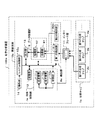
図4は、第1の分析チップ2を用いた化学分析装置100の動作を示したフローチャートである。化学分析装置100の操作者により、図5(a)に示すように、測定液量の被検試料が第1の分析チップ2の開口部から収容槽22内へ注入される。そして、測定液量の被検試料を収容した第1の分析チップ2を、図6に示すように、装置本体10の開口部111から挿入した後、装置本体10の操作部14から検査開始の操作を行うことにより、化学分析装置100は動作を開始する(ステップS1)。   FIG. 4 is a flowchart showing the operation of the chemical analysis apparatus 100 using the first analysis chip 2. As shown in FIG. 5A, the operator of the chemical analyzer 100 injects a test sample having a measurement liquid amount into the storage tank 22 from the opening of the first analysis chip 2. Then, as shown in FIG. 6, after the first analysis chip 2 containing the sample to be measured is inserted from the opening 111 of the apparatus main body 10, the inspection is started from the operation section 14 of the apparatus main body 10. By performing the operation, the chemical analyzer 100 starts operation (step S1).

システム制御部15は、操作部14からの入力情報に基づいて、液体制御部7、検出部8、データ処理部9、記憶部12、及び出力部13を制御する。液体制御部7の送液機構71は、制御部73の制御により、第1の分析チップ2の第1及び第2バルブ27,28を駆動して第1の反応流路24及び第1の圧力流路26を開放する(ステップS2)。   The system control unit 15 controls the liquid control unit 7, the detection unit 8, the data processing unit 9, the storage unit 12, and the output unit 13 based on input information from the operation unit 14. The liquid feeding mechanism 71 of the liquid control unit 7 drives the first and second valves 27 and 28 of the first analysis chip 2 to control the first reaction channel 24 and the first pressure under the control of the control unit 73. The flow path 26 is opened (step S2).

第1の圧力室25は、内部の気体の収縮により収容槽22内の被検試料で閉塞された第1の反応流路24内及び第1の反応室23内の気体を吸引して、収容槽22内の被検試料を第1の反応室23内へ送液する。   The first pressure chamber 25 sucks and stores the gas in the first reaction channel 24 and the first reaction chamber 23 that are blocked by the test sample in the storage tank 22 due to contraction of the internal gas. The test sample in the tank 22 is fed into the first reaction chamber 23.

このように、第1の分析チップ2の第1の圧力室23内に大気圧よりも低い圧力の気体を封入し、この封入した気体の収縮を利用することにより、圧力発生手段、この圧力発生手段により発生した圧力を伝達する非圧縮性媒質、及びこの非圧縮性媒質を密封する容器とダイアフラム部材により構成される送液機構を必要とせず、第1の分析チップ2の収容槽22に注入された被検試料を送液することができる。これにより、装置本体10の小型化を図ることができる。   As described above, the first pressure chamber 23 of the first analysis chip 2 is filled with the gas having a pressure lower than the atmospheric pressure, and the contraction of the enclosed gas is used to generate the pressure generating means and the pressure generation. An incompressible medium for transmitting the pressure generated by the means, and a liquid feeding mechanism constituted by a container and a diaphragm member for sealing the incompressible medium are not required, and are injected into the storage tank 22 of the first analysis chip 2. The prepared test sample can be fed. Thereby, size reduction of the apparatus main body 10 can be achieved.

第1の反応室23内へ送液された被検試料は、第1の反応室23内の気体の部分に充填された後、第1の圧力流路26へ流入する。第1の検出器29は、第1の圧力流路26へ流入した被検試料を検出し、その検出信号を検出部8の第1の検出部81を介してシステム制御部15へ出力する(ステップS3)。   The test sample sent into the first reaction chamber 23 is filled in the gas portion in the first reaction chamber 23 and then flows into the first pressure channel 26. The first detector 29 detects the test sample flowing into the first pressure channel 26 and outputs the detection signal to the system control unit 15 via the first detection unit 81 of the detection unit 8 ( Step S3).

なお、第1の反応室23内に封入された気体の部分の容積に第1の圧力流路26の一端と第1の検出器29間の容積を加算した容積よりも多く、収容槽22の容積以下の量である測定液量の被検試料が収容槽22内に収容されていると、第1の反応室23内へ送液された被検試料が第1の検出器29で検出されたとき、図5(b)に示すように、第1の反応流路24の第1のバルブ27よりも収容槽22側に被検試料が残存し、第1の反応室23内の封入されていた気体の部分に被検試料が充填されている。   Note that the volume of the portion of the gas sealed in the first reaction chamber 23 is larger than the volume obtained by adding the volume between one end of the first pressure flow path 26 and the first detector 29, and When a test sample having a volume equal to or smaller than the volume is stored in the storage tank 22, the test sample fed into the first reaction chamber 23 is detected by the first detector 29. Then, as shown in FIG. 5B, the test sample remains on the container 22 side of the first valve 27 of the first reaction channel 24 and is sealed in the first reaction chamber 23. The sample to be tested is filled in the gas portion.

システム制御部15は、第1の検出部81から出力された第1の検出器29の検出信号に基づいて、第1の反応室23が被検試料及び第1試薬で充填されていると判断し、制御部73に指示する。送液機構71は、制御部73の制御により、第1及び第2バルブ27,28を駆動して第1の反応流路24及び第1の圧力流路26を閉鎖する(ステップS4)。   The system control unit 15 determines that the first reaction chamber 23 is filled with the test sample and the first reagent based on the detection signal of the first detector 29 output from the first detection unit 81. Then, the controller 73 is instructed. Under the control of the controller 73, the liquid feeding mechanism 71 drives the first and second valves 27 and 28 to close the first reaction channel 24 and the first pressure channel 26 (step S4).

このように、第1及び第2バルブ27,28で第1の反応流路24及び第1の圧力流路26を閉鎖することにより、第1の反応室23内の第1試薬の量に応じた被検試料を定量することができる。   In this way, by closing the first reaction channel 24 and the first pressure channel 26 with the first and second valves 27 and 28, the amount of the first reagent in the first reaction chamber 23 can be increased. The test sample can be quantified.

第1の反応流路24及び第1の圧力流路26が閉鎖された後、液体制御部7の撹拌機構72は、第1の反応室23内の第1撹拌子231を駆動して第1の混合液を撹拌する(ステップS5)。   After the first reaction channel 24 and the first pressure channel 26 are closed, the stirring mechanism 72 of the liquid control unit 7 drives the first stirring bar 231 in the first reaction chamber 23 to drive the first Is mixed (step S5).

撹拌してから所定時間後に、第1の検出部81は、第1の反応室23内の第1の混合液に光を照射し、その第1の混合液内を透過した光を検出して電気信号に変換する(ステップS6)。次いで、電気信号に変換した検出信号を増幅してデータ処理部9へ出力する。   After a predetermined time after stirring, the first detection unit 81 irradiates the first mixed liquid in the first reaction chamber 23 with light, and detects the light transmitted through the first mixed liquid. It converts into an electric signal (step S6). Next, the detection signal converted into an electric signal is amplified and output to the data processing unit 9.

データ処理部9の収集部91は、検出部8の第1の検出部81から出力された信号をデジタル信号に変換する。処理部92は、収集部91から出力された信号に対応する検査項目のキャリブレーションテーブルを記憶部12から読み出した後、このキャリブレーションテーブルを用いて分析データを生成する。そして、生成した分析データを記憶部12に保存すると共に出力部13に出力する。記憶部12は、データ処理部9から出力された分析データを保存する。出力部13は、データ処理部9から出力された分析データを表示する(ステップS7)。   The collection unit 91 of the data processing unit 9 converts the signal output from the first detection unit 81 of the detection unit 8 into a digital signal. The processing unit 92 reads out from the storage unit 12 a calibration table of inspection items corresponding to the signal output from the collection unit 91, and then generates analysis data using the calibration table. The generated analysis data is stored in the storage unit 12 and output to the output unit 13. The storage unit 12 stores the analysis data output from the data processing unit 9. The output unit 13 displays the analysis data output from the data processing unit 9 (step S7).

そして、出力部13に分析データが出力された時点で、システム制御部15が、液体制御部7、検出部8、データ処理部9、記憶部12、及び出力部13を停止させることにより、化学分析装置100は測定を終了する(ステップS8)。   When the analysis data is output to the output unit 13, the system control unit 15 stops the liquid control unit 7, the detection unit 8, the data processing unit 9, the storage unit 12, and the output unit 13, thereby The analyzer 100 ends the measurement (step S8).

測定終了後、操作者は、測定を終了した第1の混合液が収容された第1の分析チップ2を装置本体10から取り外して医療廃棄物として廃棄する。   After completion of the measurement, the operator removes the first analysis chip 2 containing the first mixed liquid whose measurement has been completed from the apparatus main body 10 and discards it as medical waste.

なお、第1の分析チップ2の第1の反応室23及び第1の圧力室25を、図7に示すように、第1の反応室23a及び第1の圧力室25aに置き換えた第1の分析チップ2aを用いて測定するようにしてもよい。この第1の分析チップ2aの各ユニットは、第1の基板211及びこの第1の基板211の下面に上面が接合する第2の基板212aにより構成される基板21aの内外に配置される。第1の反応室23a内の底面を形成している第2の基板212aの下壁を貫通する貫通孔を閉塞する着脱可能な第1の栓233が配置される。また、第1の圧力室25a内の一側面を形成している第2の基板212aの他端部の側壁を貫通する貫通孔を閉塞する着脱可能な第2の栓251が配置される。   The first reaction chamber 23 and the first pressure chamber 25 of the first analysis chip 2 are replaced with a first reaction chamber 23a and a first pressure chamber 25a as shown in FIG. You may make it measure using the analysis chip 2a. Each unit of the first analysis chip 2a is arranged inside or outside the substrate 21a constituted by the first substrate 211 and the second substrate 212a whose upper surface is bonded to the lower surface of the first substrate 211. A detachable first plug 233 that closes a through-hole penetrating the lower wall of the second substrate 212a forming the bottom surface in the first reaction chamber 23a is disposed. In addition, a detachable second plug 251 that closes a through hole penetrating the side wall at the other end of the second substrate 212a forming one side surface in the first pressure chamber 25a is disposed.

そして、測定後に廃棄の対象となった第1の分析チップ2aを回収した後、第1及び第2の栓233,251を取り外して第1の分析チップ2a内の各流路及び各室を、洗浄及び消毒する。更に、第1の反応室23a内に新たに第1試薬及び第1撹拌子231を入れて第1及び第2の栓233,251を取り付けた後、第1及び第2のバルブ27,28を開閉して、第1の圧力室25aを所定の圧力に減圧封入することにより、再利用することができる。これにより、医療廃棄物を低減して限られた資源を有効に活用することができる。   And after collecting the 1st analysis chip 2a used as the object of disposal after measurement, the 1st and 2nd stoppers 233 and 251 are removed, and each channel and each room in the 1st analysis chip 2a are Clean and disinfect. Further, after the first reagent and the first stirrer 231 are newly placed in the first reaction chamber 23a and the first and second stoppers 233 and 251 are attached, the first and second valves 27 and 28 are turned on. It can be reused by opening and closing and sealing the first pressure chamber 25a under a predetermined pressure. Thereby, medical waste can be reduced and limited resources can be used effectively.

次に、図1乃至図10を参照して、分析チップ1の第2の分析チップ3の構成及び第2の分析チップ3を用いた化学分析装置100の動作の一例を説明する。図8は、第2の分析チップ3の構成を示すブロック図である。図9は、第2の分析チップ3の構造を示す図である。図10は、第2の分析チップ3を用いた化学分析装置100の動作を示すフローチャートである。以下において、第1の分析チップ2と同じ機能を有するユニットには同じ符号を付与し、その説明を簡略化又は省略する。   Next, an example of the configuration of the second analysis chip 3 of the analysis chip 1 and the operation of the chemical analysis apparatus 100 using the second analysis chip 3 will be described with reference to FIGS. FIG. 8 is a block diagram showing a configuration of the second analysis chip 3. FIG. 9 is a diagram showing the structure of the second analysis chip 3. FIG. 10 is a flowchart showing the operation of the chemical analysis apparatus 100 using the second analysis chip 3. In the following, units having the same functions as those of the first analysis chip 2 are denoted by the same reference numerals, and description thereof is simplified or omitted.

図8において、第2の分析チップ3は、収容槽22、2試薬系の各検査項目の第1試薬及び第1撹拌子231を収容した第1の反応室23、第1の反応流路24、第1の圧力室25、第1の圧力流路26、第1のバルブ27、第2のバルブ28、及び第1の検出器29の各ユニットを備えている。   In FIG. 8, the second analysis chip 3 includes a storage tank 22, a first reaction chamber 23 storing a first reagent and a first stirrer 231 for each inspection item of the two reagent system, and a first reaction channel 24. The first pressure chamber 25, the first pressure flow path 26, the first valve 27, the second valve 28, and the first detector 29 are provided.

また、第1の反応室23と第2の分析チップ3の外部の間を連通している外部流路30a、第1の反応室23と第2の反応流路30bで連通している第2の反応室32、外部流路30aを開閉する第3のバルブ30c、及び第2の反応流路30bの一端の近傍を開閉する第4のバルブ30dの各ユニットを備えている。   In addition, an external flow path 30a communicating between the first reaction chamber 23 and the outside of the second analysis chip 3, and a second communication path communicating with the first reaction chamber 23 and the second reaction flow path 30b. The reaction chamber 32, a third valve 30c for opening and closing the external flow path 30a, and a fourth valve 30d for opening and closing the vicinity of one end of the second reaction flow path 30b are provided.

更に、第2の反応室32と第2の圧力流路34で連通している第2の圧力室33、第2の反応流路30bの他端の近傍を開閉する第5のバルブ35、第2の圧力流路34を開閉する第6のバルブ36、及び第1の反応室23からの第1の混合液を検出する第2の検出器37の各ユニットを備えている。   Furthermore, a second pressure chamber 33 communicating with the second reaction chamber 32 through the second pressure channel 34, a fifth valve 35 for opening and closing the vicinity of the other end of the second reaction channel 30b, Each unit includes a sixth valve 36 that opens and closes the second pressure channel 34 and a second detector 37 that detects the first mixed liquid from the first reaction chamber 23.

図9(a)は、第2の分析チップ3の上面図であり、また図9(b)は図9(a)に示した第2の分析チップ3のB−B線における断面図であり、更に図9(c)は図9(b)に示した第2の分析チップ3のC−C線における断面図である。この第2の分析チップ3の各ユニットは、第1の分析チップ2における第1及び第2の基板211,212の追加工により形成された第1及び第2の基板211b,212b、並びにガラス、シリコン、プラスチック、セラミックス等の材料の微細加工により形成され、第2の基板212bの下面に上面が接合された第3の基板311により構成される基板31の内外に配置される。   FIG. 9A is a top view of the second analysis chip 3, and FIG. 9B is a cross-sectional view taken along the line BB of the second analysis chip 3 shown in FIG. 9A. Further, FIG. 9C is a cross-sectional view taken along the line CC of the second analysis chip 3 shown in FIG. 9B. Each unit of the second analysis chip 3 includes first and second substrates 211b and 212b formed by additional processing of the first and second substrates 211 and 212 in the first analysis chip 2, and glass, It is formed by microfabrication of a material such as silicon, plastic, ceramics, etc., and is arranged inside or outside the substrate 31 constituted by a third substrate 311 whose upper surface is bonded to the lower surface of the second substrate 212b.

外部流路30aは、一端が第1の反応室23内上部の中央付近に位置し、他端が基板31の外側面に位置している。そして、第1の反応室23と基板31外部の間を連通している。   One end of the external channel 30 a is located near the center of the upper part in the first reaction chamber 23, and the other end is located on the outer surface of the substrate 31. The first reaction chamber 23 communicates with the outside of the substrate 31.

第2の反応室32は、基板31内の第1の反応室23下方の第1の反応室23よりも他端部側に配置され、第1の反応室23に収容された第1試薬と対を成す所定量の第2試薬、及び第1の混合液と第2試薬の混合液(第2の混合液)を撹拌する第2撹拌子321を収容している。また、第2の反応室32内の互いに対向する側面を形成している基板31の第3の基板311の両側壁を貫通する2つの貫通孔が、検出部8の第1の検出部81からの光が透過する2つの透過材322で閉塞されている。   The second reaction chamber 32 is disposed on the other end side of the first reaction chamber 23 below the first reaction chamber 23 in the substrate 31, and includes the first reagent accommodated in the first reaction chamber 23. A second stirrer 321 for agitating a predetermined amount of the second reagent and a mixed liquid of the first mixed liquid and the second reagent (second mixed liquid) is accommodated. In addition, two through holes penetrating both side walls of the third substrate 311 of the substrate 31 forming side surfaces facing each other in the second reaction chamber 32 extend from the first detection unit 81 of the detection unit 8. The light is blocked by two transmitting materials 322 that transmit light.

第2の反応流路30bは、一端が第1の反応室23内の底部に位置し、他端が第2の反応室32内上部の一部に位置している。そして、第1の反応室23と第2の反応室32の間を連通している。   One end of the second reaction channel 30 b is located at the bottom of the first reaction chamber 23, and the other end is located at a part of the upper part of the second reaction chamber 32. The first reaction chamber 23 and the second reaction chamber 32 communicate with each other.

第3のバルブ30cは、外部流路30aの第1の反応室23の近傍に配置され、外部流路30aを開閉可能に閉鎖している。また、第4のバルブ30dは、第2の反応流路30bの第1の反応室23の近傍に配置され、第2の反応流路30bの一端近傍を開閉可能に閉鎖している。更に、第1及び第2のバルブ27,28は、第1の反応流路24及び第1の圧力流路26を閉鎖している。そして、第1の反応室23内に第1撹拌子231、第1試薬、及び大気圧とほぼ同じ圧力の気体を封入している。また、第1の圧力室25内に大気圧よりも低い圧力の気体を封入している。   The third valve 30c is disposed in the vicinity of the first reaction chamber 23 of the external flow path 30a, and closes the external flow path 30a so that it can be opened and closed. The fourth valve 30d is disposed in the vicinity of the first reaction chamber 23 of the second reaction channel 30b, and closes one end of the second reaction channel 30b so that it can be opened and closed. Further, the first and second valves 27 and 28 close the first reaction channel 24 and the first pressure channel 26. The first reaction chamber 23 is filled with a first stirrer 231, a first reagent, and a gas having substantially the same pressure as the atmospheric pressure. In addition, a gas having a pressure lower than the atmospheric pressure is sealed in the first pressure chamber 25.

第2の圧力室33は、第1の反応室23内の第1の混合液を第2の反応室32内へ送液するための吸引を行うために設けられ、基板31内の他端部近傍に配置される。そして、空気、窒素ガス等の気体を収容している。なお、第1の圧力室25と第2の圧力室33を合わせて1つの圧力室に置き換えるようにしてもよい。   The second pressure chamber 33 is provided to perform suction for sending the first mixed liquid in the first reaction chamber 23 into the second reaction chamber 32, and the other end portion in the substrate 31. Located in the vicinity. And gas, such as air and nitrogen gas, is accommodated. The first pressure chamber 25 and the second pressure chamber 33 may be combined and replaced with one pressure chamber.

第2の圧力流路34は、一端が第2の反応室32内上部の他部に位置し、他端が第2の圧力室33内上部に位置している。そして、第2の反応室32と第2の圧力室33の間を連通している。   One end of the second pressure channel 34 is located in the other part of the upper part in the second reaction chamber 32, and the other end is located in the upper part in the second pressure chamber 33. The second reaction chamber 32 and the second pressure chamber 33 are communicated with each other.

第5のバルブ35は、第2の反応流路30bの第2の反応室32の近傍に配置され、第2の反応流路30bの他端部近傍を開閉可能に閉鎖している。第6のバルブ36は、第2の圧力流路34の第2の反応室32の近傍に配置され、第2の圧力流路34を開閉可能に閉鎖している。   The fifth valve 35 is disposed in the vicinity of the second reaction chamber 32 of the second reaction channel 30b, and closes the vicinity of the other end of the second reaction channel 30b so as to be openable and closable. The sixth valve 36 is disposed in the vicinity of the second reaction chamber 32 of the second pressure channel 34, and closes the second pressure channel 34 so that it can be opened and closed.

そして、第2の反応室32内に第2撹拌子321、第2試薬、及び大気圧とほぼ同じ圧力の気体を封入している。また、第2の圧力室33内に大気圧よりも低い圧力の気体を封入している。このように、大気圧よりも低い圧力の気体を封入することにより、第2の圧力室33の容積を小さくすることができる。   The second reaction chamber 32 contains a second stirrer 321, a second reagent, and a gas having substantially the same pressure as the atmospheric pressure. In addition, a gas having a pressure lower than the atmospheric pressure is enclosed in the second pressure chamber 33. Thus, the volume of the second pressure chamber 33 can be reduced by enclosing the gas having a pressure lower than the atmospheric pressure.

第2の検出器37は、第2の圧力流路34の第6のバルブ36よりも第2の圧力室33側の第6のバルブ36近傍に配置される。そして、外部流路30a、第2の反応流路30b、及び第2の圧力流路34の開放により、第2の反応室32を通過して第2の圧力流路34へ流入した第1の反応室23からの第1の混合液を検出する。検出した検出信号は第1の検出部81に出力される。   The second detector 37 is arranged near the sixth valve 36 on the second pressure chamber 33 side than the sixth valve 36 of the second pressure channel 34. Then, by opening the external flow path 30a, the second reaction flow path 30b, and the second pressure flow path 34, the first flow that passes through the second reaction chamber 32 and flows into the second pressure flow path 34. The first liquid mixture from the reaction chamber 23 is detected. The detected detection signal is output to the first detection unit 81.

図10は、第2の分析チップ3を用いた化学分析装置100の動作を示したフローチャートである。化学分析装置100の操作者により、測定液量の被検試料が第2の分析チップ3の開口部から収容槽22内へ注入される。被検試料を収容した第2の分析チップ3を装置本体10の開口部111から挿入し、装置本体10の操作部14から検査開始の操作を行うことにより、化学分析装置100は動作を開始する(ステップS11)。   FIG. 10 is a flowchart showing the operation of the chemical analysis apparatus 100 using the second analysis chip 3. An operator of the chemical analyzer 100 injects a test sample having a measurement liquid amount into the storage tank 22 from the opening of the second analysis chip 3. The chemical analysis apparatus 100 starts operation by inserting the second analysis chip 3 containing the test sample from the opening 111 of the apparatus main body 10 and performing an operation for starting the inspection from the operation section 14 of the apparatus main body 10. (Step S11).

システム制御部15は、操作部14からの入力情報により、液体制御部7、検出部8、データ処理部9、記憶部12、及び出力部13を制御する。液体制御部7の送液機構71は、制御部73の制御により、第2の分析チップ3の第1及び第2バルブ27,28を駆動して第1の反応流路24及び第1の圧力流路26を開放する(ステップS12)。   The system control unit 15 controls the liquid control unit 7, the detection unit 8, the data processing unit 9, the storage unit 12, and the output unit 13 based on input information from the operation unit 14. The liquid feeding mechanism 71 of the liquid control unit 7 drives the first and second valves 27 and 28 of the second analysis chip 3 under the control of the control unit 73 to drive the first reaction channel 24 and the first pressure. The flow path 26 is opened (step S12).

第1の圧力室25は、内部の気体の収縮により収容槽22内の被検試料で閉塞された第1の反応流路24及び第1の反応室23内の気体を吸引して、収容槽22内の被検試料を第1の反応室23内へ送液する。次いで、送液された被検試料が第1の反応室23内の気体の容積の部分を充填した後、第1の圧力流路26へ流入する。   The first pressure chamber 25 sucks the gas in the first reaction channel 24 and the first reaction chamber 23 closed by the test sample in the storage tank 22 due to contraction of the internal gas, and stores the storage tank The test sample in 22 is fed into the first reaction chamber 23. Next, the liquid sample to be tested is filled in the gas volume in the first reaction chamber 23 and then flows into the first pressure channel 26.

このように、第2の分析チップ3の第1の圧力室25内に大気圧よりも低い圧力の気体を封入し、この封入した気体の収縮を利用することにより、圧力発生手段、この圧力発生手段により発生した圧力を伝達する非圧縮性媒質、この非圧縮性媒質を密封する容器、ダイアフラム部材等の送液機構を必要とせず、収容槽22に注入された被検試料を送液することができる。これにより、装置本体10の小型化を図ることができる。   As described above, the first pressure chamber 25 of the second analysis chip 3 is filled with the gas having a pressure lower than the atmospheric pressure, and the contraction of the enclosed gas is used to generate the pressure generating means and the pressure generation. The test sample injected into the storage tank 22 is sent without requiring a liquid feeding mechanism such as an incompressible medium for transmitting the pressure generated by the means, a container for sealing the incompressible medium, and a diaphragm member. Can do. Thereby, size reduction of the apparatus main body 10 can be achieved.

第1の検出器29は、第1の圧力流路26へ流入した被検試料を検出し、その検出信号を装置本体10における検出部8の第1の検出部81を介してシステム制御部15へ出力する(ステップS13)。   The first detector 29 detects the test sample that has flowed into the first pressure flow path 26, and sends the detection signal to the system control unit 15 via the first detection unit 81 of the detection unit 8 in the apparatus main body 10. (Step S13).

システム制御部15は、第1の検出部81から出力された第1の検出器29の検出信号に基づいて、第1の反応室23内が被検試料及び第1試薬で充填されていると判断し、制御部73に指示する。送液機構71は、制御部73の制御により、第1及び第2バルブ27,28を駆動して第1の反応流路24及び第1の圧力流路26を閉塞する(ステップS14)。   Based on the detection signal of the first detector 29 output from the first detection unit 81, the system control unit 15 fills the first reaction chamber 23 with the test sample and the first reagent. Determine and instruct the control unit 73. Under the control of the control unit 73, the liquid feeding mechanism 71 drives the first and second valves 27 and 28 to close the first reaction channel 24 and the first pressure channel 26 (step S14).

第1の反応流路24及び第1の圧力流路26が閉鎖された後、液体制御部7の撹拌機構72は、第1の反応室23内の第1撹拌子231を駆動して第1の混合液を撹拌する(ステップS15)。   After the first reaction channel 24 and the first pressure channel 26 are closed, the stirring mechanism 72 of the liquid control unit 7 drives the first stirring bar 231 in the first reaction chamber 23 to drive the first Are mixed (step S15).

第1の混合液を撹拌した後、送液機構71は、制御部73の制御により、第3乃至第6のバルブ30c,30d,35,36を駆動して外部流路30a、第2の反応流路30b、及び第2の圧力流路34を開放する(ステップS16)。   After stirring the first mixed liquid, the liquid feeding mechanism 71 drives the third to sixth valves 30c, 30d, 35, and 36 under the control of the control unit 73 to drive the external flow path 30a and the second reaction. The flow path 30b and the second pressure flow path 34 are opened (step S16).

なお、第1の反応室23内の撹拌した後の第1の混合液に第1の検出部81から光を照射し、その第1の混合液内を透過した光を検出して第1の混合液に含まれる被検試料による色調の変化を測定するようにしてもよい。   The first mixed liquid after stirring in the first reaction chamber 23 is irradiated with light from the first detection unit 81, and the light transmitted through the first mixed liquid is detected to detect the first mixed liquid. You may make it measure the change of the color tone by the test sample contained in a liquid mixture.

第2の圧力室33は、内部の気体の収縮により第1の反応室23内の第1の混合液で閉塞された第2の反応流路30b内及び第2の反応室32内の気体を吸引して、その第1の混合液を第2の反応室32内へ送液する。次いで、送液された第1の混合液が第2の反応室32内の気体の部分を充填した後、第2の圧力流路34へ流入する。   The second pressure chamber 33 removes the gas in the second reaction channel 30b and the second reaction chamber 32 that are blocked by the first liquid mixture in the first reaction chamber 23 due to contraction of the gas inside. The first mixed solution is sucked and fed into the second reaction chamber 32. Next, the fed first mixed liquid fills the gas portion in the second reaction chamber 32 and then flows into the second pressure channel 34.

このように、第2の分析チップ2の第2の圧力室33内に大気圧よりも低い圧力の気体を封入し、この封入した気体の収縮を利用することにより、圧力発生手段、この圧力発生手段により発生した圧力を伝達する非圧縮性媒質、この非圧縮性媒質を密封する容器、ダイアフラム部材等の送液機構を必要とせず、第1の反応室23内の第1の混合液を送液することができる。これにより、装置本体10の小型化を図ることができる。   As described above, the second pressure chamber 33 of the second analysis chip 2 is filled with the gas having a pressure lower than the atmospheric pressure, and the contraction of the enclosed gas is used to generate the pressure generating means and the pressure generation. The first mixed liquid in the first reaction chamber 23 is sent without the need for a liquid feeding mechanism such as an incompressible medium for transmitting the pressure generated by the means, a container for sealing the incompressible medium, and a diaphragm member. Can be liquid. Thereby, size reduction of the apparatus main body 10 can be achieved.

第2の検出器37は、第2の圧力流路34へ流入した第1の混合液を検出し、その検出信号を検出部8の第1の検出部81を介してシステム制御部15へ出力する(ステップS17)。   The second detector 37 detects the first mixed liquid flowing into the second pressure flow path 34 and outputs the detection signal to the system control unit 15 via the first detection unit 81 of the detection unit 8. (Step S17).

なお、第2の反応室32内へ送液された第1の混合液が第2の検出器37で検出されたとき、第2の反応流路30bの第5のバルブ35よりも第1の反応室23側に第1の混合液が残存し、第2の反応室32内の封入されていた気体の部分には第1の混合液が充填されている。   In addition, when the 1st liquid mixture sent into the 2nd reaction chamber 32 is detected with the 2nd detector 37, it is 1st rather than the 5th valve 35 of the 2nd reaction flow path 30b. The first mixed liquid remains on the reaction chamber 23 side, and the gas portion enclosed in the second reaction chamber 32 is filled with the first mixed liquid.

システム制御部15は、第1の検出部81から出力された第2の検出器37の検出信号に基づいて、第2の反応室32内が第1の混合液及び第2試薬で充填されていると判断して、制御部73に指示する。送液機構71は、制御部73の制御により、第5及び第6バルブ35,36を駆動して第2の反応流路30bの他端部近傍及び第2の圧力流路34を閉鎖する(ステップS18)。   Based on the detection signal of the second detector 37 output from the first detector 81, the system controller 15 fills the second reaction chamber 32 with the first mixed solution and the second reagent. The control unit 73 is instructed. Under the control of the control unit 73, the liquid feeding mechanism 71 drives the fifth and sixth valves 35 and 36 to close the vicinity of the other end of the second reaction channel 30b and the second pressure channel 34 ( Step S18).

このように、第5及び第6バルブ35,36で第2の反応流路30b及び第2の圧力流路34を閉塞することにより、第2の反応室32内の第2試薬の量に応じた第1の混合液を定量することができる。   Thus, by closing the second reaction channel 30b and the second pressure channel 34 with the fifth and sixth valves 35 and 36, the amount of the second reagent in the second reaction chamber 32 is determined. The first mixed liquid can be quantified.

第2の反応流路30bの他端部近傍及び第2の圧力流路34が閉鎖された後、撹拌機構72は、第2の反応室32内の第2撹拌子321を駆動して第2の混合液を撹拌する(ステップS19)。   After the vicinity of the other end of the second reaction channel 30b and the second pressure channel 34 are closed, the agitation mechanism 72 drives the second agitator 321 in the second reaction chamber 32 to generate the second Is mixed (step S19).

撹拌してから所定時間後に、第1の検出部81は、第2の反応室32内の第2の混合液に光を照射し、その第2の混合液内を透過した光を検出して電気信号に変換する(ステップS20)。次いで、電気信号に変換した検出信号を増幅してデータ処理部9へ出力する。   After a predetermined time after stirring, the first detection unit 81 irradiates the second mixed liquid in the second reaction chamber 32 with light, and detects the light transmitted through the second mixed liquid. It converts into an electric signal (step S20). Next, the detection signal converted into an electric signal is amplified and output to the data processing unit 9.

データ処理部9は、検出部8の第1の検出部81から出力された信号に基づいて分析データを生成する。そして、生成した分析データを記憶部12に保存すると共に出力部13に出力する。記憶部12は、データ処理部9から出力された分析データを保存する。出力部13は、データ処理部9から出力された分析データを表示する(ステップS21)。   The data processing unit 9 generates analysis data based on the signal output from the first detection unit 81 of the detection unit 8. The generated analysis data is stored in the storage unit 12 and output to the output unit 13. The storage unit 12 stores the analysis data output from the data processing unit 9. The output unit 13 displays the analysis data output from the data processing unit 9 (step S21).

そして、出力部13に、分析データが出力された時点で、システム制御部15が液体制御部7、検出部8、データ処理部9、記憶部12、及び出力部13を停止させることにより、化学分析装置100は測定を終了する(ステップS22)。   When the analysis data is output to the output unit 13, the system control unit 15 stops the liquid control unit 7, the detection unit 8, the data processing unit 9, the storage unit 12, and the output unit 13, thereby The analyzer 100 ends the measurement (step S22).

測定終了後、操作者は、測定を終了した各液体が収容された第2の分析チップ3を装置本体10から取り外して廃棄する。   After the measurement is completed, the operator removes the second analysis chip 3 containing the liquids for which the measurement has been completed from the apparatus main body 10 and discards it.

次に、図1乃至図12を参照して、分析チップ1の第3の分析チップ4の構成及び第3の分析チップ4を用いた化学分析装置100の動作の一例を説明する。図11は、第3の分析チップ4の構成を示すブロック図である。図12は、第3の分析チップ4の構造を示す図である。以下において、第1及び第2の分析チップ2,3と同じ機能を有するユニットには同じ符号を付与し、その説明を簡略化又は省略する。   Next, an example of the configuration of the third analysis chip 4 of the analysis chip 1 and the operation of the chemical analysis apparatus 100 using the third analysis chip 4 will be described with reference to FIGS. FIG. 11 is a block diagram showing a configuration of the third analysis chip 4. FIG. 12 is a diagram showing the structure of the third analysis chip 4. In the following, units having the same functions as those of the first and second analysis chips 2 and 3 are denoted by the same reference numerals, and description thereof is simplified or omitted.

図11において、第3の分析チップ4は、収容槽22、第1試薬及び第1撹拌子231を収容した第1の反応室23b、第1の反応流路24、第1の圧力室25、第1の圧力流路26、第1のバルブ27、第2のバルブ28、第1の検出器29、及び各検査項目の成分を特異的に検出するセンサ42の各ユニットを備えている。   In FIG. 11, the third analysis chip 4 includes a storage tank 22, a first reaction chamber 23 b that stores a first reagent and a first stirrer 231, a first reaction channel 24, a first pressure chamber 25, Each unit includes a first pressure channel 26, a first valve 27, a second valve 28, a first detector 29, and a sensor 42 that specifically detects a component of each inspection item.

図12(a)は、第3の分析チップ4の上面図であり、図12(b)は図12(a)に示した第3の分析チップ4のD−D線における断面図である。この第3の分析チップ4の各ユニットは、ガラス、シリコン、プラスチック、セラミックス等の材料を用いて微細加工することにより形成された第1の基板211及びこの第1の基板211の下面に上面が接合され第2の基板411により構成される基板41の内外に配置される。   12A is a top view of the third analysis chip 4, and FIG. 12B is a cross-sectional view taken along the line DD of the third analysis chip 4 shown in FIG. Each unit of the third analysis chip 4 has a first substrate 211 formed by microfabrication using a material such as glass, silicon, plastic, and ceramics, and an upper surface on the lower surface of the first substrate 211. It is arranged inside and outside the substrate 41 that is bonded and configured by the second substrate 411.

第1の反応室23b内の一側面を形成している基板41の第2の基板411の一側壁を貫通する貫通孔がセンサ42により閉塞されている。   A through hole penetrating one side wall of the second substrate 411 of the substrate 41 forming one side surface in the first reaction chamber 23 b is closed by the sensor 42.

センサ42は、ナトリウムイオンなどの電解質に選択的に感応するイオン選択性電極及びこの電極の基準となる参照電極により構成されるイオンセンサ、グルコースなどの検査項目の成分に選択的に反応するグルコースオキシダーゼ(GOD)等を含む高分子膜が固定化された酵素センサ等により構成される。そして、第1の反応室23b内の第1の混合液に含まれる各検査項目の成分を検出し、その検出信号を装置本体10における検出部8の第2の検出部82へ出力する。   The sensor 42 includes an ion-selective electrode that is selectively sensitive to an electrolyte such as sodium ion, an ion sensor that includes a reference electrode that serves as a reference for the electrode, and a glucose oxidase that selectively reacts with components of a test item such as glucose It is composed of an enzyme sensor or the like to which a polymer film containing (GOD) or the like is immobilized. And the component of each test | inspection item contained in the 1st liquid mixture in the 1st reaction chamber 23b is detected, and the detection signal is output to the 2nd detection part 82 of the detection part 8 in the apparatus main body 10. FIG.

次に、第3の分析チップ4を用いた化学分析装置100の動作について説明する。第3の分析チップ4を用いた化学分析装置100が、第1の分析チップ2を用いた場合と同様に動作する図4のステップS1乃至S5及びステップS7,S8の説明を省略し、ステップS6と異なるステップの動作を説明する。   Next, the operation of the chemical analysis apparatus 100 using the third analysis chip 4 will be described. The description of steps S1 to S5 and steps S7 and S8 in FIG. 4 in which the chemical analysis apparatus 100 using the third analysis chip 4 operates in the same manner as when using the first analysis chip 2 is omitted, and step S6 is performed. The operation of steps different from the above will be described.

このステップにおいて、第1の反応室23b内の第1の混合液を撹拌してから所定時間後に、センサ42はその第1の混合液に含まれる各検査項目の成分を検出し、その検出信号を第2の検出部82へ出力する。第2の検出部82は、センサ42からの検出信号を増幅してデータ処理部9へ出力する。   In this step, a predetermined time after stirring the first mixed liquid in the first reaction chamber 23b, the sensor 42 detects a component of each inspection item contained in the first mixed liquid, and the detection signal Is output to the second detector 82. The second detection unit 82 amplifies the detection signal from the sensor 42 and outputs it to the data processing unit 9.

以上述べた本発明の実施例1によれば、各第1乃至第3の分析チップ2,3,4の各第1の圧力室25内に大気圧よりも低い圧力の気体を封入し、第1及び第2のバルブ27,28で第1の反応流路24及び第1の圧力流路26を開放することにより、収容槽22内の被検試料を各第1の反応室23,23b内へ送液することができる。   According to the first embodiment of the present invention described above, a gas having a pressure lower than the atmospheric pressure is sealed in each first pressure chamber 25 of each of the first to third analysis chips 2, 3, 4. By opening the first reaction channel 24 and the first pressure channel 26 with the first and second valves 27 and 28, the test sample in the storage tank 22 is placed in each of the first reaction chambers 23 and 23b. Can be sent to

また、第2の分析チップ3の第2の圧力室33内に大気圧よりも低い気体を封入し、第3乃至第6のバルブ30c,30d,35,36で外部流路30a、第2の反応流路30b、及び第2の圧力流路34を開放することにより、第2の反応室32内へ第1の混合液を送液することができる。   Further, a gas lower than atmospheric pressure is sealed in the second pressure chamber 33 of the second analysis chip 3, and the external flow path 30 a and the second flow path are constituted by the third to sixth valves 30 c, 30 d, 35 and 36. By opening the reaction flow path 30 b and the second pressure flow path 34, the first mixed liquid can be sent into the second reaction chamber 32.

これにより、圧力発生手段、この圧力発生手段により発生した圧力を伝達する非圧縮性媒質、この非圧縮性媒質を密封する容器、ダイアフラム部材等の送液機構を必要とせず、装置本体10の小型化を図ることができる。   This eliminates the need for pressure generating means, an incompressible medium that transmits the pressure generated by the pressure generating means, a container for sealing the incompressible medium, a diaphragm member, and the like, and does not require a liquid feeding mechanism. Can be achieved.

そして、第1の検出器29で被検試料を検出したとき、第1及び第2のバルブ27,28で第1の反応流路24及び第1の圧力流路26を閉鎖することにより、各第1の反応室23,23b内の第1試薬の量に応じた被検試料を定量することができる。また、第2の検出器37で第1の混合液を検出したとき、第5及び第6のバルブ35,36で第2の反応流路30b及び第2の圧力流路34を閉鎖することにより、第2の反応室32内の第2試薬の量に応じた第1の混合液を定量することができる。   Then, when the test sample is detected by the first detector 29, the first reaction channel 24 and the first pressure channel 26 are closed by the first and second valves 27 and 28, respectively. The test sample according to the amount of the first reagent in the first reaction chamber 23, 23b can be quantified. Further, when the first mixed liquid is detected by the second detector 37, the second reaction channel 30b and the second pressure channel 34 are closed by the fifth and sixth valves 35 and 36. The first mixed liquid according to the amount of the second reagent in the second reaction chamber 32 can be quantified.

なお、上述した実施例1に限定されるものではなく、図13に示すように、N種類(N>1)の検査項目の測定が可能な第4の分析チップ5を用いて測定するように実施してもよい。この第4の分析チップ5は、N種類の例えば1試薬系の検査項目に対応する第1の分析チップ2の収容槽22を除いた各ユニットにより構成されるN個の第1の分析部2c1乃至2cNと、このN個の第1の分析部2c1乃至2cNの各第1の反応流路の一端が底部に位置する収容槽22aとを備えている。   In addition, it is not limited to Example 1 mentioned above, As shown in FIG. 13, it measures so that it may measure using the 4th analysis chip 5 which can measure the inspection item of N types (N> 1). You may implement. The fourth analysis chip 5 includes N first analysis units 2c1 configured by units other than the storage tank 22 of the first analysis chip 2 corresponding to N types of test items of, for example, one reagent system. To 2cN, and a storage tank 22a in which one end of each first reaction channel of the N first analysis units 2c1 to 2cN is located at the bottom.

図14(a)は、第4の分析チップ5の上面図であり、図14(b)は図14(a)に示した第4の分析チップ5のE−E線における断面図である。この第4の分析チップ5の各ユニットは、第1の分析部2c1乃至2cNの各第1の反応室内の第1の混合液に照射する光を透過する材料を用いて微細加工することにより形成されたガラス、プラスチック等の第1の基板511、この第1の基板511の下面に上面が接合された第2の基板512、及びこの第2の基板512の下面に上面が接合された第1の基板511と同じ材料からなる第3の基板513により構成される基板51の内外に配置される。これにより、第1の分析部2c1乃至2cNの各第1の反応室内の上壁及び下壁は第1及び第3の基板511,513により形成される。   FIG. 14A is a top view of the fourth analysis chip 5, and FIG. 14B is a cross-sectional view taken along line EE of the fourth analysis chip 5 shown in FIG. Each unit of the fourth analysis chip 5 is formed by microfabrication using a material that transmits light irradiating the first liquid mixture in each of the first reaction chambers of the first analysis units 2c1 to 2cN. The first substrate 511 made of glass, plastic or the like, the second substrate 512 whose upper surface is bonded to the lower surface of the first substrate 511, and the first substrate whose upper surface is bonded to the lower surface of the second substrate 512 The third substrate 513 made of the same material as the first substrate 511 is disposed inside and outside the substrate 51. Accordingly, the upper and lower walls of the first reaction chambers of the first analysis units 2c1 to 2cN are formed by the first and third substrates 511 and 513.

また、装置本体10に、第4の分析チップ5の保持が可能な開口部を有するインターフェース部、及び第1の分析部2c1乃至2cNに対応するN個の第1の検出部81a1乃至81aN、及び第1の分析部2c1乃至2cNの制御が可能な液体制御部を設ける。そして、収容槽22aの被検試料を第1の分析部2c1乃至2cNの各第1の反応室内へ送液し、各第1の反応室内の第1の混合液に対して光の照射及び検出を行うことにより、同時に複数の検査項目の測定を行うことができる。   In addition, the apparatus main body 10 includes an interface unit having an opening capable of holding the fourth analysis chip 5, and N first detection units 81a1 to 81aN corresponding to the first analysis units 2c1 to 2cN, and A liquid control unit capable of controlling the first analysis units 2c1 to 2cN is provided. Then, the test sample in the storage tank 22a is fed into each first reaction chamber of the first analysis units 2c1 to 2cN, and light irradiation and detection are performed on the first mixed solution in each first reaction chamber. By performing this, a plurality of inspection items can be measured simultaneously.

更に、各第1の反応室にセンサ42を配置し、このセンサ42に応じた数の第2の検出部を設けることにより、同時に複数の検査項目を測定することができる。   Furthermore, by arranging the sensors 42 in each first reaction chamber and providing the number of second detection units corresponding to the sensors 42, a plurality of inspection items can be measured simultaneously.

これにより、前記送液機構を必要とせず、被検試料を同時に複数の検査項目を測定することが可能となり、装置本体の小型化を図ることができる。   Thereby, it is possible to measure a plurality of inspection items of the test sample at the same time without requiring the liquid feeding mechanism, and the apparatus main body can be downsized.

以下、本発明に係る化学分析装置の実施例2を、図15及び図22を参照して説明する。
図15は、実施例2に係る化学分析装置の構成を示したブロック図である。図15に示した実施例2が図1における実施例1と大きく異なる点は、実施例1に係る分析チップ1における各第1乃至第3の分析チップ2,3,4の第1の圧力室25を大気圧よりも大きな圧力の気体を封入した第1の圧力室に置き換えた点と、実施例2に係る図15の分析チップを制御する液体制御部に置き換えた点である。以下では、実施例2に係る各ユニットの実施例1と同様に機能するユニットは同じ符号を付与し説明を簡略化又は省略する。
Hereinafter, Example 2 of the chemical analyzer according to the present invention will be described with reference to FIGS. 15 and 22.
FIG. 15 is a block diagram illustrating the configuration of the chemical analyzer according to the second embodiment. The second embodiment shown in FIG. 15 is significantly different from the first embodiment shown in FIG. 1 in that the first pressure chambers of the first to third analysis chips 2, 3 and 4 in the analysis chip 1 according to the first embodiment. 25 is replaced with a first pressure chamber filled with a gas having a pressure higher than atmospheric pressure, and a liquid control unit for controlling the analysis chip of FIG. 15 according to the second embodiment. Below, the unit which functions similarly to Example 1 of each unit which concerns on Example 2 gives the same code | symbol, and simplifies or abbreviate | omits description.

図15において、化学分析装置100aは、被検試料と試薬を混合して各検査項目を測定するための分析チップ1a、及びこの分析チップ1aの測定により得られた信号を処理して分析データを生成する装置本体10aを備えている。   In FIG. 15, the chemical analyzer 100a processes an analysis chip 1a for mixing a test sample and a reagent and measuring each inspection item, and a signal obtained by the measurement of the analysis chip 1a to obtain analysis data. An apparatus main body 10a for generation is provided.

分析チップ1aは、各検査項目の測定方法に応じて、光学的に測定する検査項目の試薬が1試薬系である場合の第1試薬を収容した第1の分析チップ2c、光学的に測定する検査項目の試薬が2試薬系である場合の第1及び第2試薬を収容した第2の分析チップ3a、及び電気化学的に測定する検査項目である場合の第1試薬を収容した第3の分析チップ4a等により構成される。   The analysis chip 1a optically measures the first analysis chip 2c containing the first reagent when the reagent of the test item to be optically measured is a single reagent system according to the measurement method of each test item. The second analysis chip 3a containing the first and second reagents when the reagent of the test item is a two-reagent system, and the third containing the first reagent when the test item is an electrochemical measurement item It is comprised by the analysis chip 4a etc.

装置本体10aは、着脱可能な分析チップ1aを保持するインターフェース部11、分析チップ1aを制御する液体制御部7a、分析チップ1aによる測定により得られた信号を検出する検出部8a、データ処理部9、記憶部12、出力部13、及び操作部14と、液体制御部7a、検出部8a、データ処理部9、記憶部12、及び出力部13の制御やシステム全体の制御を統括して行うシステム制御部15aとを備えている。   The apparatus main body 10a includes an interface unit 11 that holds a removable analysis chip 1a, a liquid control unit 7a that controls the analysis chip 1a, a detection unit 8a that detects a signal obtained by measurement using the analysis chip 1a, and a data processing unit 9. , A storage unit 12, an output unit 13, and an operation unit 14, and a system that performs overall control of the liquid control unit 7a, detection unit 8a, data processing unit 9, storage unit 12, and output unit 13 and overall system control. And a control unit 15a.

液体制御部7aは、インターフェース部11に保持された分析チップ1aの近傍に配置され、分析チップ1aの各ユニットを駆動して分析チップ1a内の被検試料等を送液する送液機構71aと、被検試料と試薬の混合液を撹拌する撹拌機構72aと、送液機構71a及び撹拌機構72aを制御する制御部73aとを備えている。   The liquid control unit 7a is disposed in the vicinity of the analysis chip 1a held by the interface unit 11, and drives a unit of the analysis chip 1a to send a test sample or the like in the analysis chip 1a. , A stirring mechanism 72a for stirring the mixed solution of the test sample and the reagent, and a controller 73a for controlling the liquid feeding mechanism 71a and the stirring mechanism 72a.

検出部8aは、インターフェース部11に保持された各第1及び第2の分析チップ2c,3aに係合する第1の検出部81a、及び第3の分析チップ4aに係合する第2の検出部82aを備えている。第1の検出部81aは、実施例1における第1の検出部81と同様に光源及び受光素子を有する。そして、各第1及び第2の分析チップ2c,3a内の混合液に光を照射し、その混合液内を透過した光を検出して電気信号に変換する。更にその電気信号を増幅してデータ処理部9へ出力する。また、各第1及び第2の分析チップ2c,3a内における被検試料等の検出信号を受信してシステム制御部15aへ出力する。   The detection unit 8a includes a first detection unit 81a that engages with each of the first and second analysis chips 2c and 3a held by the interface unit 11, and a second detection that engages with the third analysis chip 4a. A portion 82a is provided. The first detection unit 81a includes a light source and a light receiving element in the same manner as the first detection unit 81 in the first embodiment. Then, the mixed liquid in each of the first and second analysis chips 2c and 3a is irradiated with light, and the light transmitted through the mixed liquid is detected and converted into an electric signal. Further, the electric signal is amplified and output to the data processing unit 9. In addition, detection signals such as a test sample in each of the first and second analysis chips 2c and 3a are received and output to the system control unit 15a.

第2の検出部82aは、第3の分析チップ4a内の混合液の測定により検出された検出信号を受信して増幅する。そして増幅した信号をデータ処理部9へ出力する。また、第3の分析チップ4a内における被検試料の検出信号を受信してシステム制御部15aへ出力する。   The second detection unit 82a receives and amplifies the detection signal detected by measuring the mixed solution in the third analysis chip 4a. Then, the amplified signal is output to the data processing unit 9. Further, the detection signal of the test sample in the third analysis chip 4a is received and output to the system control unit 15a.

以下、分析チップ1aの各第1乃至第3の分析チップ2c,3a,4aの構成の詳細、及び各第1乃至第3の分析チップ2c,3a,4aを用いた化学分析装置100aの動作の一例を説明する。
先ず、図15乃至図17を参照して、分析チップ1aの第1の分析チップ2cの構成及び第1の分析チップ2cを用いた化学分析装置100aの動作を説明する。図16は、第1の分析チップ2cの構成を示すブロック図である。図17は、第1の分析チップ2cの構造を示す図である。
Hereinafter, the detailed configuration of each of the first to third analysis chips 2c, 3a, 4a of the analysis chip 1a and the operation of the chemical analysis apparatus 100a using each of the first to third analysis chips 2c, 3a, 4a will be described. An example will be described.
First, the configuration of the first analysis chip 2c of the analysis chip 1a and the operation of the chemical analysis apparatus 100a using the first analysis chip 2c will be described with reference to FIGS. FIG. 16 is a block diagram showing a configuration of the first analysis chip 2c. FIG. 17 is a diagram showing the structure of the first analysis chip 2c.

図16において、第1の分析チップ2cは、収容槽22b、第1の反応室23c、第1の反応流路24a、第1の圧力室25b、第1の圧力流路26a、第1の外部流路50、第1のバルブ27a、第7のバルブ51、第2のバルブ28a、及び第1の検出器29aの各ユニットを備えている。   In FIG. 16, the first analysis chip 2c includes a storage tank 22b, a first reaction chamber 23c, a first reaction channel 24a, a first pressure chamber 25b, a first pressure channel 26a, and a first external. Each unit includes a flow channel 50, a first valve 27a, a seventh valve 51, a second valve 28a, and a first detector 29a.

図17(a)は、第1の分析チップ2cの上面図であり、図17(b)は図17(a)に示した第1の分析チップ2cのF−F線における断面図である。この第1の分析チップ2cの各ユニットは、ガラス、シリコン、プラスチック、セラミックス等の材料の微細加工により形成された第1の基板211c及びこの第1の基板211cの下面に上面が接合された第2の基板212cにより構成される基板21cの内外に配置される。   FIG. 17A is a top view of the first analysis chip 2c, and FIG. 17B is a cross-sectional view taken along the line FF of the first analysis chip 2c shown in FIG. Each unit of the first analysis chip 2c includes a first substrate 211c formed by microfabrication of a material such as glass, silicon, plastic, ceramics, etc., and an upper surface bonded to the lower surface of the first substrate 211c. Two substrates 212c are arranged inside and outside the substrate 21c.

収容槽22bは、基板21c上面の中央よりも一端部よりに配置された開口部を有し、その開口部から注入された被検試料を収容する。   The storage tank 22b has an opening disposed at one end rather than the center of the upper surface of the substrate 21c, and stores the test sample injected from the opening.

第1の反応室23cは、基板21c内の収容槽22bよりも他端部側に配置され、各検査項目に応じた所定量の第1試薬、及びこの第1試薬と被検試料の第1の混合液を撹拌するための第1撹拌子231を収容している。また、第1の反応室23c内の互いに対向する側面を形成している基板21cの第2の基板212cの両側壁を貫通する2つの貫通孔が、装置本体10aにおける検出部8aの第1の検出部81aからの光が透過する2つの透過材232により閉塞されている。第1の撹拌子231は、装置本体10aにおける液体制御部7aの撹拌機構72aにより第1の混合液を撹拌する。   The first reaction chamber 23c is arranged on the other end side of the storage tank 22b in the substrate 21c, and a predetermined amount of the first reagent according to each inspection item, and the first reagent and the first sample of the test sample. The first stirring bar 231 for stirring the mixed solution is accommodated. Further, two through holes penetrating both side walls of the second substrate 212c of the substrate 21c forming the mutually opposing side surfaces in the first reaction chamber 23c are the first of the detection unit 8a in the apparatus main body 10a. The light is blocked by two transmission materials 232 through which light from the detection unit 81a is transmitted. The first stirring bar 231 stirs the first mixed liquid by the stirring mechanism 72a of the liquid control unit 7a in the apparatus main body 10a.

第1の反応流路24aは、一端が収容槽22b内の底部に位置し、他端が第1の反応室23c内上部の一部に位置している。そして、収容槽22bと第1の反応室23cの間を連通している。   One end of the first reaction channel 24a is located at the bottom of the storage tank 22b, and the other end is located at a part of the upper part of the first reaction chamber 23c. And the storage tank 22b and the 1st reaction chamber 23c are connected.

第1の圧力室25bは、基板21c内の収容槽22bよりも一端部側に配置され、空気、窒素ガス等の気体を収容している。   The first pressure chamber 25b is disposed on one end side of the storage tank 22b in the substrate 21c and stores a gas such as air or nitrogen gas.

第1の圧力流路26aは、一端が第1の圧力室25b内上部に位置し、他端が収容槽22b内上部に位置している。そして、第1の圧力室25bと収容槽22bの間を連通している。第1の外部流路50は、一端が第1の反応室23c内上部の他部に位置し、他端が基板21cの他端面に位置している。そして、第1の反応室23cと基板21cの外部の間を連通している。   One end of the first pressure channel 26a is located in the upper part in the first pressure chamber 25b, and the other end is located in the upper part in the storage tank 22b. The first pressure chamber 25b communicates with the storage tank 22b. One end of the first external channel 50 is located at the other part of the upper part in the first reaction chamber 23c, and the other end is located at the other end surface of the substrate 21c. The first reaction chamber 23c communicates with the outside of the substrate 21c.

第1のバルブ27aは、第1の反応流路24aの第1の反応室23cの近傍に配置され、第1の反応流路24aを開閉可能に閉鎖している。また、第7のバルブ51は、第1の外部流路50の第1の反応室23cの近傍に配置され、第1の外部流路50を開閉可能に閉鎖している。そして、第1の反応室23c内に第1撹拌子231、第1試薬、及び大気圧とほぼ同じ圧力の気体を封入している。   The first valve 27a is disposed in the vicinity of the first reaction chamber 23c of the first reaction channel 24a, and closes the first reaction channel 24a so that it can be opened and closed. The seventh valve 51 is disposed in the vicinity of the first reaction chamber 23c of the first external flow path 50, and closes the first external flow path 50 so that it can be opened and closed. And the 1st stirring bar 231, the 1st reagent, and the gas of the pressure substantially the same as atmospheric pressure are enclosed in the 1st reaction chamber 23c.

また、第2のバルブ28aは、第1の圧力流路26aに配置され、第1の圧力流路26aを開閉可能に閉鎖している。そして、第1の圧力室25b内に大気圧よりも高い圧力の気体を封入している。このように、大気圧よりも高い圧力の気体を封入することにより、第1の圧力室25bの容積を小さくすることができる。   The second valve 28a is disposed in the first pressure channel 26a, and closes the first pressure channel 26a so that it can be opened and closed. And the gas of the pressure higher than atmospheric pressure is enclosed in the 1st pressure chamber 25b. Thus, the volume of the 1st pressure chamber 25b can be made small by enclosing the gas of pressure higher than atmospheric pressure.

第1の検出器29aは、第1の外部流路50の第7のバルブ51よりも基板21cの他端部側の第7のバルブ51近傍に配置される。そして、送液機構71aによる収容槽22bの開口部の閉塞及び第1の反応流路24a、第1の圧力流路26a、第1の外部流路50の開放により、第1の反応室23cを通過して第1の外部流路50へ流入した収容槽22bからの被検試料を検出する。検出した検出信号は、第1の検出部81aに出力される。   The first detector 29a is disposed near the seventh valve 51 on the other end side of the substrate 21c with respect to the seventh valve 51 of the first external flow path 50. Then, the first reaction chamber 23c is opened by closing the opening of the storage tank 22b by the liquid feeding mechanism 71a and opening the first reaction channel 24a, the first pressure channel 26a, and the first external channel 50. A test sample from the storage tank 22b that has passed through and flows into the first external channel 50 is detected. The detected detection signal is output to the first detection unit 81a.

次に、第1の分析チップ2cを用いた化学分析装置100aの動作を説明する。
測定液量の被検試料が開口部から収容槽22b内へ注入された第1の分析チップ2cが装置本体10aの開口部111から挿入される。装置本体10aにおける液体制御部7aの送液機構71aは、制御部73aの制御により第1の分析チップ2cの収容槽22bの開口部を閉塞した後、第1及び第2バルブ27a,28a並びに第7のバルブ51を駆動して第1の圧力流路26a、第1の反応流路24a、及び第1の外部流路50を開放する。
Next, the operation of the chemical analysis apparatus 100a using the first analysis chip 2c will be described.
The first analysis chip 2c into which the test sample of the measurement liquid amount is injected into the storage tank 22b from the opening is inserted from the opening 111 of the apparatus main body 10a. The liquid feeding mechanism 71a of the liquid control unit 7a in the apparatus main body 10a closes the opening of the storage tank 22b of the first analysis chip 2c under the control of the control unit 73a, and then the first and second valves 27a, 28a and the first. 7 valve 51 is driven to open first pressure channel 26a, first reaction channel 24a, and first external channel 50.

第1の圧力室25bは、内部の気体の膨張により収容槽22b内を加圧して、収容槽22b内の被検試料を第1の反応室23c内へ送液する。   The first pressure chamber 25b pressurizes the inside of the storage tank 22b by the expansion of the internal gas, and sends the test sample in the storage tank 22b into the first reaction chamber 23c.

このように、第1の分析チップ2cの第1の圧力室25b内に大気圧よりも高い圧力の気体を封入し、この封入した気体の膨張を利用することにより、圧力発生手段、この圧力発生手段により発生した圧力を伝達する非圧縮性媒質、この非圧縮性媒質を密封する容器、ダイアフラム部材等の送液機構を必要とせず、収容槽22bに注入された被検試料を送液することができる。これにより、装置本体10aの小型化を図ることができる。   In this way, by enclosing a gas having a pressure higher than the atmospheric pressure in the first pressure chamber 25b of the first analysis chip 2c and utilizing the expansion of the enclosed gas, the pressure generating means, the pressure generation The test sample injected into the storage tank 22b is sent without requiring a liquid feeding mechanism such as an incompressible medium for transmitting the pressure generated by the means, a container for sealing the incompressible medium, and a diaphragm member. Can do. Thereby, size reduction of the apparatus main body 10a can be achieved.

次いで、送液された被検試料が第1の反応室23c内の気体の部分に充填された後、第1の外部流路50へ流入する。第1の検出器29aは、第1の外部流路50へ流入した被検試料を検出し、その検出信号を検出部8aの第1の検出部81aを介してシステム制御部15aへ出力する。   Next, the sent test sample is filled in the gas portion in the first reaction chamber 23 c and then flows into the first external channel 50. The first detector 29a detects the test sample flowing into the first external flow path 50, and outputs the detection signal to the system control unit 15a via the first detection unit 81a of the detection unit 8a.

なお、第1の反応室23c内に封入された気体の部分の容積に第1の外部流路50の一端と第1の検出器29a間の容積を加算した容積よりも多く、収容槽22bの容積以下の量である測定液量の被検試料が収容槽22b内に収容されていると、第1の反応室23c内へ送液された被検試料が第1の検出器29aで検出されたとき、第1の反応流路24aの第1のバルブ27aよりも収容槽22b側に被検試料が残存し、第1の反応室23c内の封入されていた気体の部分に被検試料が充填されている。   Note that the volume of the portion of the gas sealed in the first reaction chamber 23c is larger than the volume obtained by adding the volume between one end of the first external flow path 50 and the first detector 29a to the volume of the storage tank 22b. When a test sample having a volume equal to or smaller than the volume is stored in the storage tank 22b, the test sample fed into the first reaction chamber 23c is detected by the first detector 29a. In this case, the test sample remains on the container 22b side of the first valve 27a of the first reaction flow path 24a, and the test sample is placed in the gas portion enclosed in the first reaction chamber 23c. Filled.

システム制御部15aは、第1の検出部81aから出力された第1の検出器29aの検出信号に基づいて、第1の反応室23c内に被検試料及び第1試薬が充填されていると判断し、液体制御部7aの制御部73aに指示する。送液機構71aは、制御部73aの制御により、第1及び第7のバルブ27a,51を駆動して第1の反応流路24a及び第1の外部流路50を閉鎖する。   When the system control unit 15a fills the test sample and the first reagent in the first reaction chamber 23c based on the detection signal of the first detector 29a output from the first detection unit 81a. Determine and instruct the control unit 73a of the liquid control unit 7a. The liquid feeding mechanism 71a drives the first and seventh valves 27a and 51 under the control of the control unit 73a to close the first reaction channel 24a and the first external channel 50.

第1の反応流路24a及び第1の外部流路50が閉鎖された後、液体制御部7aの撹拌機構72aは、第1の反応室23c内の第1撹拌子231を駆動して第1の混合液を撹拌する。撹拌してから所定時間後に、第1の検出部81aは、第1の反応室23c内の第1の混合液に光を照射し、その第1の混合液内を透過した光を検出して電気信号に変換する。次いで、電気信号に変換した検出信号を増幅してデータ処理部9へ出力する。   After the first reaction channel 24a and the first external channel 50 are closed, the agitation mechanism 72a of the liquid control unit 7a drives the first agitator 231 in the first reaction chamber 23c to drive the first Stir the mixture. After a predetermined time after stirring, the first detection unit 81a irradiates the first mixed liquid in the first reaction chamber 23c with light, and detects the light transmitted through the first mixed liquid. Convert to electrical signal. Next, the detection signal converted into an electric signal is amplified and output to the data processing unit 9.

データ処理部9は、検出部8aの第1の検出部81aから出力された信号に基づいて、分析データを生成する。そして、生成した分析データを記憶部12に保存すると共に出力部13に表示する。   The data processing unit 9 generates analysis data based on the signal output from the first detection unit 81a of the detection unit 8a. The generated analysis data is stored in the storage unit 12 and displayed on the output unit 13.

次に、図15乃至図19を参照して、分析チップ1aの第2の分析チップ3aの構成及び第2の分析チップ3aを用いた化学分析装置100aの動作の一例を説明する。図18は、第2の分析チップ3aの構成を示すブロック図である。図19は、第2の分析チップ3aの構造を示す図である。以下において、第1の分析チップ2cと同じ機能を有するユニットには同じ符号を付与し、その説明を簡略化又は省略する。   Next, an example of the configuration of the second analysis chip 3a of the analysis chip 1a and the operation of the chemical analysis apparatus 100a using the second analysis chip 3a will be described with reference to FIGS. FIG. 18 is a block diagram showing a configuration of the second analysis chip 3a. FIG. 19 is a diagram showing the structure of the second analysis chip 3a. In the following, units having the same functions as those of the first analysis chip 2c are denoted by the same reference numerals, and description thereof is simplified or omitted.

図18において、第2の分析チップ3aは、収容槽22b、第1試薬及び第1撹拌子231を収容した第1の反応室23c、第1の反応流路24a、第1の圧力室25b、第1の圧力流路26a、第1の外部流路50、第1のバルブ27a、第7のバルブ51、第2のバルブ28a、及び第1の検出器29aの各ユニットを備えている。   In FIG. 18, the second analysis chip 3a includes a storage tank 22b, a first reaction chamber 23c storing a first reagent and a first stirring bar 231, a first reaction flow path 24a, a first pressure chamber 25b, Each unit includes a first pressure channel 26a, a first external channel 50, a first valve 27a, a seventh valve 51, a second valve 28a, and a first detector 29a.

また、第2の外部流路30aa、第2の反応流路30ba、第3のバルブ30ca、第4のバルブ30da、第1の反応室23cの第1試薬と対を成す第2試薬及び第2撹拌子321を収容した第2の反応室32a、第2の圧力室33a、第2の圧力流路34a、第5のバルブ35a、第6のバルブ36a、及び第2の検出器37aの各ユニットを備えている。   In addition, the second external channel 30aa, the second reaction channel 30ba, the third valve 30ca, the fourth valve 30da, the second reagent that forms a pair with the first reagent in the first reaction chamber 23c, and the second reagent Each unit of the second reaction chamber 32a, the second pressure chamber 33a, the second pressure channel 34a, the fifth valve 35a, the sixth valve 36a, and the second detector 37a containing the stir bar 321 It has.

図19(a)は、第2の分析チップ3aの上面図であり、図19(b)は図19(a)に示した第2の分析チップ3aのG−G線における断面図である。この第2の分析チップ3aの各ユニットは、第1の分析チップ2cにおける第1及び第2の基板211c,212cの追加工により形成された第1及び第2の基板211d,212d、並びにガラス、シリコン、プラスチック、セラミックス等の材料の微細加工により形成され、第2の基板212dの下面に上面が接合された第3の基板311aにより構成される基板31aの内外に配置される。   FIG. 19A is a top view of the second analysis chip 3a, and FIG. 19B is a cross-sectional view taken along line GG of the second analysis chip 3a shown in FIG. Each unit of the second analysis chip 3a includes first and second substrates 211d and 212d formed by additional processing of the first and second substrates 211c and 212c in the first analysis chip 2c, and glass, It is formed by microfabrication of a material such as silicon, plastic, ceramics, etc., and is arranged inside or outside the substrate 31a constituted by the third substrate 311a whose upper surface is bonded to the lower surface of the second substrate 212d.

第2の外部流路30aaは、一端が第1の反応室23c内の上部の中央付近に位置し、他端が基板31aの外側面に位置している。そして、第1の反応室23cと基板31aの外部の間を連通している。また、第2の反応流路30baは、一端が第1の反応室23c内の底部に位置し、他端が第2の反応室32a内上部の一部に位置している。そして、第1の反応室23cと第2の反応室32aの間を連通している。   One end of the second external flow path 30aa is located near the center of the upper part in the first reaction chamber 23c, and the other end is located on the outer surface of the substrate 31a. The first reaction chamber 23c communicates with the outside of the substrate 31a. One end of the second reaction channel 30ba is located at the bottom of the first reaction chamber 23c, and the other end is located at a part of the upper part of the second reaction chamber 32a. The first reaction chamber 23c and the second reaction chamber 32a communicate with each other.

第3のバルブ30caは、第2の外部流路30aaの第1の反応室23cの近傍に配置され、送液機構71aにより第2の外部流路30aaを開閉可能に閉鎖している。また、第4のバルブ30daは、第2の反応流路30baの第1の反応室23cの近傍に配置され、第2の反応流路30baの一端近傍を開閉可能に閉鎖している。更に、第1及び第7のバルブ27a,51は、第1の反応流路24a及び第1の外部流路50を閉鎖している。そして、第1の反応室23c内に第1撹拌子231、第1試薬、及び大気圧とほぼ同じ圧力の気体を封入している。   The third valve 30ca is disposed in the vicinity of the first reaction chamber 23c of the second external flow path 30aa, and closes the second external flow path 30aa so that it can be opened and closed by the liquid feeding mechanism 71a. The fourth valve 30da is disposed in the vicinity of the first reaction chamber 23c of the second reaction channel 30ba, and closes one end of the second reaction channel 30ba so that it can be opened and closed. Further, the first and seventh valves 27 a and 51 close the first reaction channel 24 a and the first external channel 50. And the 1st stirring bar 231, the 1st reagent, and the gas of the pressure substantially the same as atmospheric pressure are enclosed in the 1st reaction chamber 23c.

第2の反応室32aは、基板31a内の第1の反応室23c下方の第1の反応室23cよりも他端部側に配置され、基板31aの第3の基板311aの両側壁を貫通する2つの貫通孔が2つの透過材322により閉塞されている。   The second reaction chamber 32a is disposed on the other end side of the first reaction chamber 23c below the first reaction chamber 23c in the substrate 31a, and penetrates both side walls of the third substrate 311a of the substrate 31a. Two through holes are closed by two permeable members 322.

第2の圧力室33aは、基板31a内の他端部近傍に配置され、空気、窒素ガス等の気体を収容している。また、第2の圧力流路34aは、一端が第2の反応室32a内上部の他部に位置し、他端が第2の圧力室33a内上部に位置している。そして、第2の反応室32aと第2の圧力室33aの間を連通している。   The second pressure chamber 33a is disposed in the vicinity of the other end in the substrate 31a and accommodates a gas such as air or nitrogen gas. The second pressure channel 34a has one end located in the other part of the upper part in the second reaction chamber 32a and the other end located in the upper part in the second pressure chamber 33a. The second reaction chamber 32a communicates with the second pressure chamber 33a.

第5のバルブ35aは、第2の反応流路30baの第2の反応室32aの近傍に配置され、第2の反応流路30baの他端部近傍を開閉可能に閉鎖している。また、第6のバルブ36aは、第2の圧力流路34aの第2の反応室32aの近傍に配置され、第2の圧力流路34aを開閉可能に閉鎖している。そして、第2の反応室32a内に第2撹拌子321、第2試薬、及び大気圧とほぼ同じ圧力の気体を封入している。また、第2の圧力室33a内に大気圧よりも低い圧力の気体を封入している。このように、大気圧よりも低い圧力の気体を封入することにより、第2の圧力室33aの容積を小さくすることができる。   The fifth valve 35a is disposed in the vicinity of the second reaction chamber 32a of the second reaction channel 30ba, and closes the vicinity of the other end of the second reaction channel 30ba so that it can be opened and closed. The sixth valve 36a is disposed in the vicinity of the second reaction chamber 32a of the second pressure channel 34a, and closes the second pressure channel 34a so that it can be opened and closed. And the 2nd stirring bar 321, the 2nd reagent, and the gas of the pressure substantially the same as atmospheric pressure are enclosed in the 2nd reaction chamber 32a. In addition, a gas having a pressure lower than the atmospheric pressure is sealed in the second pressure chamber 33a. Thus, the volume of the second pressure chamber 33a can be reduced by enclosing the gas having a pressure lower than the atmospheric pressure.

第2の検出器37aは、第2の圧力流路34aの第6のバルブ36aよりも第2の圧力室33a側の第6のバルブ36a近傍に配置される。そして、第2の外部流路30aa、第2の反応流路30ba、及び第2の圧力流路34aの開放により、第2の反応室32aを通過して第2の圧力流路34aへ流入した第1の反応室23cからの第1の混合液を検出する。検出した検出信号は第1の検出部81aに出力される。   The second detector 37a is arranged near the sixth valve 36a on the second pressure chamber 33a side than the sixth valve 36a of the second pressure channel 34a. Then, by opening the second external channel 30aa, the second reaction channel 30ba, and the second pressure channel 34a, the second external channel 30aa flows into the second pressure channel 34a through the second reaction chamber 32a. The first liquid mixture from the first reaction chamber 23c is detected. The detected detection signal is output to the first detection unit 81a.

次に第2の分析チップ3aを用いた化学分析装置100aの動作の一例を説明する。
測定液量の被検試料が開口部から収容槽22b内へ注入された第2の分析チップ3aが装置本体10aの開口部111から挿入される。装置本体10aにおける液体制御部7aの送液機構71aは、制御部73aの制御により、第2の分析チップ3aの収容槽22bの開口部を閉塞した後、第1及び第2バルブ27a,28a並びに第7のバルブ51を駆動して第1の圧力流路26a、第1の反応流路24a、及び第1の外部流路50を開放する。
Next, an example of the operation of the chemical analysis apparatus 100a using the second analysis chip 3a will be described.
The second analysis chip 3a in which the sample to be measured is injected into the storage tank 22b from the opening is inserted from the opening 111 of the apparatus main body 10a. The liquid feeding mechanism 71a of the liquid control unit 7a in the apparatus main body 10a closes the opening of the storage tank 22b of the second analysis chip 3a under the control of the control unit 73a, and then the first and second valves 27a, 28a and The seventh valve 51 is driven to open the first pressure channel 26a, the first reaction channel 24a, and the first external channel 50.

第1の圧力室25bは、内部の気体の膨張により収容槽22b内を加圧して、収容槽22b内の被検試料を第1の反応室23c内へ送液する。次いで、送液された被検試料が第1の反応室23c内の気体の部分を充填した後、第1の外部流路50へ流入する。   The first pressure chamber 25b pressurizes the inside of the storage tank 22b by the expansion of the internal gas, and sends the test sample in the storage tank 22b into the first reaction chamber 23c. Next, the sent test sample fills the gas portion in the first reaction chamber 23 c and then flows into the first external channel 50.

このように、第2の分析チップ3aの第1の圧力室25b内に大気圧よりも高い圧力の気体を封入し、この封入した気体の膨張を利用することにより、圧力発生手段、この圧力発生手段により発生した圧力を伝達する非圧縮性媒質、この非圧縮性媒質を密封する容器、ダイアフラム部材等の送液機構を必要とせず、収容槽22bに注入された被検試料を送液することができる。これにより、装置本体10aの小型化を図ることができる。   In this way, by enclosing a gas having a pressure higher than the atmospheric pressure in the first pressure chamber 25b of the second analysis chip 3a and utilizing the expansion of the enclosed gas, the pressure generating means, the pressure generation The test sample injected into the storage tank 22b is sent without requiring a liquid feeding mechanism such as an incompressible medium for transmitting the pressure generated by the means, a container for sealing the incompressible medium, and a diaphragm member. Can do. Thereby, size reduction of the apparatus main body 10a can be achieved.

第1の検出器29aは、第1の外部流路50へ流入した被検試料を検出し、その検出信号を検出部8aの第1の検出部81aを介してシステム制御部15aへ出力する。システム制御部15aは、第1の検出部81aから出力された第1の検出器29aの検出信号に基づいて、第1の反応室23c内に被検試料及び第1試薬が充填されていると判断し、制御部73aに指示する。   The first detector 29a detects the test sample flowing into the first external flow path 50, and outputs the detection signal to the system control unit 15a via the first detection unit 81a of the detection unit 8a. When the system control unit 15a fills the test sample and the first reagent in the first reaction chamber 23c based on the detection signal of the first detector 29a output from the first detection unit 81a. Determine and instruct the controller 73a.

送液機構71aは、制御部73aの制御により、第1及び第7のバルブ27a,51を駆動して第1の反応流路24a及び第1の外部流路50を閉鎖する。第1の反応流路24a及び第1の外部流路50が閉鎖された後、液体制御部7aの撹拌機構72aは、第1の反応室23c内の第1撹拌子231を駆動して第1の混合液を撹拌する。   The liquid feeding mechanism 71a drives the first and seventh valves 27a and 51 under the control of the control unit 73a to close the first reaction channel 24a and the first external channel 50. After the first reaction channel 24a and the first external channel 50 are closed, the agitation mechanism 72a of the liquid control unit 7a drives the first agitator 231 in the first reaction chamber 23c to drive the first Stir the mixture.

撹拌してから所定時間後に、送液機構71aは、第3乃至第6のバルブ30ca,30da,35a,36aを駆動して、第2の外部流路30aa、第2の反応流路30ba、及び第2の圧力流路34aを開放する。   After a predetermined time from the stirring, the liquid feeding mechanism 71a drives the third to sixth valves 30ca, 30da, 35a, 36a, the second external channel 30aa, the second reaction channel 30ba, and The second pressure channel 34a is opened.

第2の圧力室33aは、内部の気体の収縮により第1の反応室23c内の第1の混合液を吸引して、第2の反応室32a内へ送液する。次いで、送液された第1の混合液が第2の反応室32a内の気体の部分を充填した後、第2の圧力流路34aへ流入する。   The second pressure chamber 33a sucks the first mixed liquid in the first reaction chamber 23c by the contraction of the gas inside, and sends the liquid into the second reaction chamber 32a. Next, the fed first mixed liquid fills the gas portion in the second reaction chamber 32a and then flows into the second pressure channel 34a.

このように、第2の分析チップ3aの第2の圧力室33a内に大気圧よりも低い圧力の気体を封入し、この封入した気体の膨張を利用することにより、圧力発生手段、この圧力発生手段により発生した圧力を伝達する非圧縮性媒質、この非圧縮性媒質を密封する容器、ダイアフラム部材等の送液機構を必要とせず、第1の反応室23c内の第1の混合液を送液することができる。これにより、装置本体10aの小型化を図ることができる。   In this way, by enclosing a gas having a pressure lower than the atmospheric pressure in the second pressure chamber 33a of the second analysis chip 3a, and utilizing the expansion of the enclosed gas, the pressure generating means, the pressure generation The first mixed liquid in the first reaction chamber 23c is fed without requiring a liquid feeding mechanism such as an incompressible medium for transmitting the pressure generated by the means, a container for sealing the incompressible medium, and a diaphragm member. Can be liquid. Thereby, size reduction of the apparatus main body 10a can be achieved.

第2の検出器37aは、第2の圧力流路34aへ流入した第1の混合液を検出し、その検出信号を第1の検出部81aを介してシステム制御部15aへ出力する。システム制御部15aは、第1の検出部81aから出力された第2の検出器37aの検出信号に基づいて、第2の反応室32a内が第1の混合液及び第2試薬で充填されていると判断し、制御部73aに指示する。   The second detector 37a detects the first mixed liquid flowing into the second pressure channel 34a, and outputs the detection signal to the system control unit 15a via the first detection unit 81a. Based on the detection signal of the second detector 37a output from the first detector 81a, the system controller 15a fills the second reaction chamber 32a with the first mixed solution and the second reagent. The control unit 73a is instructed.

送液機構71aは、制御部73aの制御により、第5及び第6のバルブ35a,36aを駆動して第2の反応流路30ba及び第2の圧力流路34aを閉鎖する。第2の反応流路30ba及び第2の圧力流路34aが閉鎖された後、撹拌機構72aは、第2の反応室32a内の第2撹拌子321を駆動して第2の混合液を撹拌する。   The liquid feeding mechanism 71a drives the fifth and sixth valves 35a and 36a to close the second reaction channel 30ba and the second pressure channel 34a under the control of the control unit 73a. After the second reaction channel 30ba and the second pressure channel 34a are closed, the stirring mechanism 72a drives the second stirrer 321 in the second reaction chamber 32a to stir the second mixed liquid. To do.

撹拌してから所定時間後に、第1の検出部81aは、第2の反応室32a内の第2の混合液に光を照射し、その第2の混合液内を透過した光を検出して電気信号に変換する。次いで、電気信号に変換した検出信号を増幅してデータ処理部9へ出力する。データ処理部9は、第1の検出部81aから出力された信号に基づいて分析データを生成する。そして、生成した分析データを記憶部12に保存すると共に出力部13に表示する。   After a predetermined time after stirring, the first detection unit 81a irradiates the second mixed liquid in the second reaction chamber 32a with light, and detects the light transmitted through the second mixed liquid. Convert to electrical signal. Next, the detection signal converted into an electric signal is amplified and output to the data processing unit 9. The data processing unit 9 generates analysis data based on the signal output from the first detection unit 81a. The generated analysis data is stored in the storage unit 12 and displayed on the output unit 13.

次に、図15乃至図21を参照して、分析チップ1aの第3の分析チップ4aの構成及び第3の分析チップ4aを用いた化学分析装置100aの動作を説明する。図20は、第3の分析チップ4aの構成を示すブロック図である。図21は、第3の分析チップ4aの構造を示す図である。以下において、第1及び第2の分析チップ2c,3aと同じ機能を有するユニットには同じ符号を付与し、その説明を簡略化又は省略する。   Next, the configuration of the third analysis chip 4a of the analysis chip 1a and the operation of the chemical analysis apparatus 100a using the third analysis chip 4a will be described with reference to FIGS. FIG. 20 is a block diagram showing the configuration of the third analysis chip 4a. FIG. 21 is a diagram showing the structure of the third analysis chip 4a. In the following, units having the same functions as those of the first and second analysis chips 2c and 3a are assigned the same reference numerals, and description thereof is simplified or omitted.

図20において、第3の分析チップ4aは、収容槽22b、第1試薬及び第1撹拌子231を収容した第1の反応室23d、第1の反応流路24a、第1の圧力室25b、第1の圧力流路26a、第1の外部流路50、第1のバルブ27a、第7のバルブ51、第2のバルブ28a、及び第1の検出器29a、及び各検査項目の成分を特異的に検出するセンサ42の各ユニットを備えている。   In FIG. 20, the third analysis chip 4a includes a storage tank 22b, a first reaction chamber 23d that stores a first reagent and a first stirrer 231, a first reaction channel 24a, a first pressure chamber 25b, The first pressure channel 26a, the first external channel 50, the first valve 27a, the seventh valve 51, the second valve 28a, the first detector 29a, and the components of each test item are specific. Each unit of sensor 42 to detect automatically is provided.

図21(a)は、第3の分析チップ4aの上面図であり、図21(b)は図21(a)に示した第3の分析チップ4aのJ−J線における断面図である。この第3の分析チップ4aの各ユニットは、ガラス、シリコン、プラスチック、セラミックス等の材料を用いて微細加工することにより形成された第1の基板211c及びこの第1の基板211cの下面に上面が接合され第2の基板411aにより構成される基板41aの内外に配置される。   FIG. 21A is a top view of the third analysis chip 4a, and FIG. 21B is a cross-sectional view taken along the line JJ of the third analysis chip 4a shown in FIG. Each unit of the third analysis chip 4a has a first substrate 211c formed by microfabrication using a material such as glass, silicon, plastic, and ceramics, and an upper surface on the lower surface of the first substrate 211c. The substrate 41a is bonded and disposed inside and outside the substrate 41a.

第1の反応室23d内の一側面を形成している基板41aの第2の基板411aの一側壁を貫通する貫通孔がセンサ42により閉塞されている。そして、センサ42は、第1の反応室23d内の第1の混合液に含まれる各検査項目の成分を検出し、その検出信号を装置本体10aにおける検出部8aの第2の検出部82aへ出力する。   A through hole penetrating one side wall of the second substrate 411 a of the substrate 41 a forming one side surface in the first reaction chamber 23 d is closed by the sensor 42. The sensor 42 detects a component of each inspection item contained in the first liquid mixture in the first reaction chamber 23d, and sends the detection signal to the second detection unit 82a of the detection unit 8a in the apparatus main body 10a. Output.

次に、第3の分析チップ4aを用いた化学分析装置100aの動作について説明する。第3の分析チップ4aを用いた化学分析装置100aは、第1の分析チップ2cを用いた場合と異なるステップの動作を説明する。このステップにおいて、第1の反応室23d内の第1の混合液を撹拌してから所定時間後に、センサ42はその第1の混合液に含まれる各検査項目の成分を検出し、その検出信号を第2の検出部82aへ出力する。第2の検出部82aは、センサ42からの検出信号を増幅してデータ処理部9へ出力する。   Next, the operation of the chemical analysis apparatus 100a using the third analysis chip 4a will be described. The chemical analysis apparatus 100a using the third analysis chip 4a will explain the operation of steps different from the case of using the first analysis chip 2c. In this step, a predetermined time after stirring the first mixed liquid in the first reaction chamber 23d, the sensor 42 detects the component of each inspection item contained in the first mixed liquid, and the detection signal Is output to the second detector 82a. The second detection unit 82 a amplifies the detection signal from the sensor 42 and outputs it to the data processing unit 9.

以上述べた本発明の実施例2によれば、各第1乃至第3の分析チップ2c,3a,4aの各第1の圧力室25b内に大気圧よりも高い圧力の気体を封入し、第1及び第2のバルブ27a,28a並びに第7のバルブ51で第1の反応流路24a、第1の圧力流路26a、及び第1の外部流路50を開放することにより、収容槽22b内の被検試料を各第1の反応室23c,23d内へ送液することができる。   According to the second embodiment of the present invention described above, a gas having a pressure higher than the atmospheric pressure is sealed in each first pressure chamber 25b of each of the first to third analysis chips 2c, 3a, 4a. By opening the first reaction channel 24a, the first pressure channel 26a, and the first external channel 50 with the first and second valves 27a, 28a and the seventh valve 51, the inside of the storage tank 22b The test sample can be fed into the first reaction chambers 23c and 23d.

また、第2の分析チップ3aの第2の圧力室33a内に大気圧よりも低い気体を封入し、第3乃至第6のバルブ30ca,30da,35a,36aで第2の外部流路30aa、第2の反応流路30ba、及び第2の圧力流路34aを開放することにより、第2の反応室32a内へ第1の混合液を送液することができる。   In addition, a gas lower than atmospheric pressure is sealed in the second pressure chamber 33a of the second analysis chip 3a, and the second external flow path 30aa, the third to sixth valves 30ca, 30da, 35a, 36a, By opening the second reaction channel 30ba and the second pressure channel 34a, the first mixed solution can be fed into the second reaction chamber 32a.

これにより、圧力発生手段、この圧力発生手段により発生した圧力を伝達する非圧縮性媒質、この非圧縮性媒質を密封する容器、ダイアフラム部材等の送液機構を必要とせず、装置本体10aの小型化を図ることができる。   This eliminates the need for a pressure generating means, an incompressible medium that transmits the pressure generated by the pressure generating means, a container for sealing the incompressible medium, a diaphragm member, and the like, and a small size of the apparatus main body 10a. Can be achieved.

そして、第1の検出器29aで被検試料を検出したとき、第1及び第2のバルブ27a,28aで第1の反応流路24a及び第1の圧力流路26aを閉鎖することにより、各第1の反応室23c,23d内の第1試薬の量に応じた被検試料を定量することができる。また、第2の検出器37aで第1の混合液を検出したとき、第5及び第6のバルブ35a,36aで第2の反応流路30ba及び第2の圧力流路34aを閉鎖することにより、第2の反応室32a内の第2試薬の量に応じた第1の混合液を定量することができる。   When the test sample is detected by the first detector 29a, each of the first reaction channel 24a and the first pressure channel 26a is closed by the first and second valves 27a and 28a. The test sample according to the amount of the first reagent in the first reaction chambers 23c and 23d can be quantified. Further, when the first mixed liquid is detected by the second detector 37a, the second reaction channel 30ba and the second pressure channel 34a are closed by the fifth and sixth valves 35a and 36a. The first mixed liquid according to the amount of the second reagent in the second reaction chamber 32a can be quantified.

なお、上述した実施例2に限定されるものではなく、図22(a)に示すように、例えば第1の分析チップ2cから第2のバルブ28aを除き、第2の基板212cを追加工して第1の圧力室25bを拡張する。また、液体制御部7aに加熱手段を設ける。そして、加熱して第1の圧力室内の気体を熱膨張させることにより、閉塞された収容槽22b内を加圧して被検試料を各第1の反応室23c,23d内に送液するようにしてもよい。   In addition, it is not limited to Example 2 mentioned above, and as shown to Fig.22 (a), the 2nd board | substrate 212c is additionally processed except the 2nd valve | bulb 28a from the 1st analysis chip 2c, for example. Thus, the first pressure chamber 25b is expanded. Moreover, a heating means is provided in the liquid control unit 7a. Then, by heating and thermally expanding the gas in the first pressure chamber, the inside of the closed storage tank 22b is pressurized and the test sample is sent into the first reaction chambers 23c and 23d. May be.

また、図22(b)に示すように、拡張した第1の圧力室内の底部に熱で屈曲可能なバイメタル60、このバイメタル60の上に第1の圧力室内の側壁に密着して上下移動可能なピストン61を配置する。そして、加熱して第1の圧力室内のバイメタル60を屈曲させてピストン61を上へ移動させることにより、閉塞された収容槽22b内を加圧して被検試料を各第1の反応室23c,23d内に送液するようにしてもよい。   Further, as shown in FIG. 22B, a bimetal 60 that can be bent by heat at the bottom of the expanded first pressure chamber, and can be moved up and down in close contact with the side wall of the first pressure chamber on the bimetal 60. A piston 61 is arranged. Then, by heating and bending the bimetal 60 in the first pressure chamber and moving the piston 61 upward, the inside of the closed storage tank 22b is pressurized to apply the test sample to each first reaction chamber 23c, You may make it liquid-feed in 23d.

これにより、圧力発生手段、この圧力発生手段により発生した圧力を伝達する非圧縮性媒質、この非圧縮性媒質を密封する容器、ダイアフラム部材等の送液機構を必要とせず、装置本体の小型化を図ることができる。   As a result, there is no need for pressure generating means, an incompressible medium for transmitting the pressure generated by the pressure generating means, a container for sealing the incompressible medium, or a liquid feeding mechanism such as a diaphragm member. Can be achieved.

本発明の実施例1に係る化学分析装置の構成を示すブロック図。1 is a block diagram showing a configuration of a chemical analysis apparatus according to Embodiment 1 of the present invention. 本発明の実施例1に係る第1の分析チップの構成を示すブロック図。The block diagram which shows the structure of the 1st analysis chip concerning Example 1 of the present invention. 本発明の実施例1に係る第1の分析チップの構造を示す図。The figure which shows the structure of the 1st analysis chip concerning Example 1 of the present invention. 本発明の実施例1に係る第1の分析チップを用いた化学分析装置の動作を示すフローチャート。The flowchart which shows operation | movement of the chemical analyzer using the 1st analysis chip concerning Example 1 of the present invention. 本発明の実施例1に係る第1の分析チップ内における被検試料の送液を説明するための図。The figure for demonstrating the liquid feeding of the test sample in the 1st analysis chip which concerns on Example 1 of this invention. 本発明の実施例1に係る第1の分析チップ及び装置本体の外観を示す図。The figure which shows the external appearance of the 1st analysis chip which concerns on Example 1 of this invention, and an apparatus main body. 本発明の実施例1に係る第1の分析チップの変形例を示す断面図。Sectional drawing which shows the modification of the 1st analysis chip concerning Example 1 of the present invention. 本発明の実施例1に係る第2の分析チップの構成を示すブロック図。The block diagram which shows the structure of the 2nd analysis chip which concerns on Example 1 of this invention. 本発明の実施例1に係る第2の分析チップの構造を示す図。The figure which shows the structure of the 2nd analysis chip which concerns on Example 1 of this invention. 本発明の実施例1に係る第2の分析チップを用いた化学分析装置の動作を示すフローチャート。The flowchart which shows operation | movement of the chemical analyzer using the 2nd analysis chip concerning Example 1 of the present invention. 本発明の実施例1に係る第3の分析チップの構成を示すブロック図。The block diagram which shows the structure of the 3rd analysis chip concerning Example 1 of the present invention. 本発明の実施例1に係る第3の分析チップの構造を示す図。The figure which shows the structure of the 3rd analysis chip concerning Example 1 of the present invention. 本発明の実施例1に係る第4の分析チップの構成を示すブロック図。The block diagram which shows the structure of the 4th analysis chip concerning Example 1 of the present invention. 本発明の実施例1に係る第4の分析チップの構造を示す図。The figure which shows the structure of the 4th analysis chip concerning Example 1 of the present invention. 本発明の実施例2に係る化学分析装置の構成を示すブロック図。The block diagram which shows the structure of the chemical analyzer which concerns on Example 2 of this invention. 本発明の実施例2に係る第1の分析チップの構成を示すブロック図。The block diagram which shows the structure of the 1st analysis chip concerning Example 2 of the present invention. 本発明の実施例2に係る第1の分析チップの構造を示す図。The figure which shows the structure of the 1st analysis chip which concerns on Example 2 of this invention. 本発明の実施例2に係る第2の分析チップの構成を示すブロック図。The block diagram which shows the structure of the 2nd analysis chip which concerns on Example 2 of this invention. 本発明の実施例2に係る第2の分析チップの構造を示す図。The figure which shows the structure of the 2nd analysis chip which concerns on Example 2 of this invention. 本発明の実施例2に係る第3の分析チップの構成を示すブロック図。The block diagram which shows the structure of the 3rd analysis chip concerning Example 2 of the present invention. 本発明の実施例2に係る第3の分析チップの構造を示す図。The figure which shows the structure of the 3rd analysis chip concerning Example 2 of the present invention. 本発明の実施例2に係る第1の分析チップの他の例を説明するための図。The figure for demonstrating the other example of the 1st analysis chip concerning Example 2 of the present invention.

符号の説明Explanation of symbols

2 第1の分析チップ
21 基板
22 収容槽
23 第1の反応室
24 第1の反応流路
25 第1の圧力室
26 第1の圧力流路
27 第1のバルブ
28 第2のバルブ
29 第1の検出器
211 第1の基板
212 第2の基板
231 第1撹拌子
232 透過材
2 First analysis chip 21 Substrate 22 Storage tank 23 First reaction chamber 24 First reaction channel 25 First pressure chamber 26 First pressure channel 27 First valve 28 Second valve 29 First Detector 211 first substrate 212 second substrate 231 first stirrer 232 transmitting material

Claims (14)

分析チップに収容された被検試料及び試薬の混合液を測定する化学分析装置において、前記分析チップは、
基板上に前記被検試料を注入するための開口部を有する収容槽と、
前記収容槽と連通可能に前記基板内に配置され、前記収容槽内に注入された被検試料及び第1試薬の混合液である第1の混合液を収容するための第1の反応室と、
前記基板内に配置され、前記第1の反応室と連通可能に大気圧よりも低い圧力の気体が封入された第1の圧力室と、
前記収容槽内と前記第1の圧力室の連通を開閉する開閉手段とを備え、
前記開閉手段を開いて前記収容槽内の被検試料を前記第1の反応室内へ送液した後、前記開閉手段を閉じるようにしたこと特徴とする化学分析装置。
In a chemical analysis apparatus for measuring a mixed solution of a test sample and a reagent contained in an analysis chip, the analysis chip includes:
A storage tank having an opening for injecting the test sample onto the substrate;
A first reaction chamber disposed in the substrate so as to be able to communicate with the storage tank, and for storing a first mixed liquid which is a mixed liquid of a test sample and a first reagent injected into the storage tank; ,
A first pressure chamber disposed in the substrate and sealed with a gas having a pressure lower than atmospheric pressure so as to be able to communicate with the first reaction chamber;
Opening and closing means for opening and closing the communication between the storage tank and the first pressure chamber,
A chemical analysis apparatus characterized in that the opening / closing means is opened and the test sample in the storage tank is fed into the first reaction chamber, and then the opening / closing means is closed .
前記開閉手段は、前記収容槽内の底部と前記第1の反応室内上部の一部の間を連通している第1の反応流路を開閉可能に閉鎖した第1の開閉手段、及び前記第1の反応室内上部の他部と前記第1の圧力室内の間を連通している第1の圧力流路を開閉可能に閉鎖した第2の開閉手段を有し、
前記第1及び第2の開閉手段による前記第1の反応流路及び前記第1の圧力流路の開放により、前記収容槽内の被検試料を前記第1の反応室内へ送液するようにしたことを特徴とする請求項1に記載の化学分析装置。
The opening / closing means includes a first opening / closing means that closes a first reaction channel that communicates between a bottom portion in the storage tank and a part of an upper portion of the first reaction chamber, and the first opening / closing means, A second opening / closing means for closing the first pressure channel communicating between the other part of the upper part of the reaction chamber and the first pressure chamber so as to be openable and closable;
The test sample in the storage tank is fed into the first reaction chamber by opening the first reaction channel and the first pressure channel by the first and second opening / closing means. The chemical analyzer according to claim 1, wherein
前記第1及び第2の開閉手段の前記第1の反応流路及び前記第1の圧力流路を開閉する位置が前記第1の反応室の近傍に配置され、
前記第1の反応室内に収容された前記第1試薬、及び前記第1の圧力流路を開閉する位置よりも前記第1の圧力室側の前記第1の圧力流路の開閉位置の近傍に配置された前記収容槽からの被検試料を検出する第1の検出手段を有し、
前記第1の検出手段により前記収容槽からの被検試料が検出されたとき、前記第1及び第2の開閉手段により前記第1の反応流路及び前記第1の圧力流路を閉鎖して、前記第1の反応室内の第1試薬の量に応じた前記収容槽からの被検試料を定量するようにしたことを特徴とする請求項2に記載の化学分析装置。
Positions for opening and closing the first reaction channel and the first pressure channel of the first and second opening and closing means are disposed in the vicinity of the first reaction chamber;
The first reagent housed in the first reaction chamber and a position closer to the opening / closing position of the first pressure channel on the first pressure chamber side than a position to open / close the first pressure channel. A first detection means for detecting a test sample from the storage tank disposed;
When the test sample from the storage tank is detected by the first detection means, the first reaction channel and the first pressure channel are closed by the first and second opening / closing means. 3. The chemical analyzer according to claim 2, wherein the test sample from the storage tank is quantified according to the amount of the first reagent in the first reaction chamber.
前記第1の反応室と連通可能に前記基板内に配置され、前記第1の反応室内に収容された前記第1の混合液及び前記第1試薬と対を成す第2試薬の混合液である第2の混合液を収容するための第2の反応室を有し、
前記第2の反応室は、前記第1の圧力室又は前記基板内に配置された前記気体が封入された第2の圧力室と連通可能であって、
前記収容槽内の被検試料を前記第1の反応室内へ送液して、前記開閉手段によって前記収容槽内と前記第1の反応室内の間を連通している第1の反応流路を閉じた後、前記第1の反応室内の第1の混合液を前記第2の反応室内へ送液することを特徴とする請求項1乃至請求項3のいずれか1項に記載の化学分析装置。
A liquid mixture of the second reagent that is disposed in the substrate so as to communicate with the first reaction chamber and that forms a pair with the first reagent and the first reagent accommodated in the first reaction chamber. Having a second reaction chamber for containing the second mixture;
The second reaction chamber can communicate with the first pressure chamber or the second pressure chamber filled with the gas disposed in the substrate,
A first reaction channel is formed in which the test sample in the storage tank is fed into the first reaction chamber, and the opening and closing means communicates between the storage tank and the first reaction chamber. after closing, the chemical analysis apparatus according to any one of claims 1 to 3, characterized in that feeding a first mixture of the first reaction chamber into said second reaction chamber .
前記開閉手段は、前記第1の反応室内の上部と前記基板の外部の間を連通している外部流路を開閉可能に閉鎖した第3の開閉手段、前記第1の反応室内底部と前記第2の反応室内上部の一部の間を連通している第2の反応流路を開閉可能に閉鎖した第4の開閉手段、前記第2の反応室内上部の他部と前記第1の圧力室又は前記第2の圧力室内の間を連通している第2の圧力流路を開閉可能に閉鎖した第5の開閉手段を有し
前記第3乃至第5の開閉手段による前記外部流路、前記第2の反応流路、及び前記第2の圧力流路の開放により、前記第1の反応室内の第1の混合液を前記第2の反応室内へ送液するようにしたことを特徴とする請求項4に記載の化学分析装置。
The opening / closing means includes third opening / closing means for closing and opening an external flow path communicating between the upper portion of the first reaction chamber and the outside of the substrate, the first reaction chamber bottom, and the first reaction chamber. A fourth opening / closing means for closing the second reaction channel communicating with a part of the upper part of the two reaction chambers, and the other part of the upper part of the second reaction chamber and the first pressure chamber. Or a fifth opening / closing means for closing the second pressure channel communicating between the second pressure chambers so as to be openable and closable ;
By opening the external flow path, the second reaction flow path, and the second pressure flow path by the third to fifth opening / closing means, the first mixed liquid in the first reaction chamber is moved to the first flow path. The chemical analysis apparatus according to claim 4, wherein liquid is fed into the reaction chamber of 2.
前記第3乃至第5の開閉手段の前記外部流路、前記第2の反応流路、及び前記第2の圧力流路を開閉する位置が前記第1の反応室の近傍に配置され、
前記開閉手段は、前記第2の反応室内に収容された前記第2試薬、前記第2の反応流路の前記第2の反応室の近傍を開閉可能に閉鎖した第6の開閉手段を有し、
前記第2の圧力流路を開閉する位置よりも前記第1の圧力室又は前記第2の圧力室側の前記第2の圧力流路開閉位置の近傍に配置された前記第1の反応室からの第1の混合液を検出する第2の検出手段を有し、
前記第2の検出手段により前記第1の混合液が検出されたとき、前記第6及び第5の開閉手段により前記第2の反応流路及び前記第2の圧力流路を閉鎖して、前記第2の反応室内の第2試薬の量に応じた前記第1の混合液を定量するようにしたことを特徴とする請求項5に記載の化学分析装置。
Positions for opening and closing the external flow path, the second reaction flow path, and the second pressure flow path of the third to fifth opening / closing means are disposed in the vicinity of the first reaction chamber,
It said closing means comprises said second reagent contained in the second reaction chamber, the sixth opening and closing means which is openably closing the vicinity of the second reaction chamber of the second reaction channel ,
From the first reaction chamber disposed closer to the first pressure chamber or the second pressure channel opening / closing position on the second pressure chamber side than the position to open / close the second pressure channel. Second detection means for detecting the first mixed liquid of
When the first mixed liquid is detected by the second detecting means, the second reaction channel and the second pressure channel are closed by the sixth and fifth opening / closing means, 6. The chemical analysis apparatus according to claim 5, wherein the first mixed liquid according to the amount of the second reagent in the second reaction chamber is quantified.
分析チップに収容された被検試料及び試薬の混合液を測定する化学分析装置において、前記分析チップは、
基板上に前記被検試料を注入するための閉塞可能な開口部を有する収容槽と、
前記基板の外部及び前記収容槽と連通可能に前記基板内に配置され、前記収容槽内に注入された被検試料及び前記試薬の混合液を収容するための反応室と、
前記基板内に配置され、前記収容槽と連通可能に大気圧よりも高い圧力の気体が封入された圧力室と、
前記反応室と前記第1の圧力室の連通を開閉する開閉手段とを備え、
前記開閉手段を開いて前記収容槽内の被検試料を前記第1の反応室内へ送液した後、前記開閉手段を閉じるようにしたことを特徴とする化学分析装置。
In a chemical analysis apparatus for measuring a mixed solution of a test sample and a reagent contained in an analysis chip, the analysis chip includes:
A storage tank having a closable opening for injecting the test sample onto the substrate;
A reaction chamber disposed in the substrate so as to be able to communicate with the outside of the substrate and the storage tank, and for storing a test sample and a mixed solution of the reagent injected into the storage tank;
A pressure chamber disposed in the substrate and filled with a gas having a pressure higher than atmospheric pressure so as to be able to communicate with the storage tank;
Opening and closing means for opening and closing the communication between the reaction chamber and the first pressure chamber;
A chemical analyzer characterized in that the opening / closing means is opened and the test sample in the storage tank is fed into the first reaction chamber, and then the opening / closing means is closed .
前記開閉手段は、前記収容槽内の底部と前記反応室内上部の一部の間を連通している反応流路を開閉可能に閉鎖した第1の開閉手段、前記収容槽内上部と前記圧力室内の間を連通している圧力流路を開閉可能に閉鎖した第2の開閉手段、及び前記反応室内上部の他部と前記基板の外部の間を連通している外部流路を開閉可能に閉鎖した第3の開閉手段を有し、
前記第1乃至第3の開閉手段による前記反応流路、前記圧力流路、及び前記外部流路の開放により、前記開口部が閉塞された前記収容槽内の被検試料を前記反応室内へ送液するようにしたことを特徴とする請求項7に記載の化学分析装置。
The opening / closing means is a first opening / closing means for closing a reaction flow path communicating between a bottom portion in the storage tank and a part of the upper part of the reaction chamber so as to be openable and closable; A second opening / closing means for closing the pressure channel communicating with each other, and an external channel communicating between the other upper part of the reaction chamber and the outside of the substrate so as to be opened / closed The third opening / closing means
The test sample in the storage tank in which the opening is closed by opening the reaction channel, the pressure channel, and the external channel by the first to third opening / closing means is sent into the reaction chamber. 8. The chemical analyzer according to claim 7, wherein the chemical analyzer is liquid.
分析チップに収容された被検試料及び試薬の混合液を測定する化学分析装置において、前記分析チップは、
基板上に前記被検試料を注入するための閉塞可能な開口部を有する収容槽と、
前記基板の外部及び前記収容槽と連通可能に前記基板内に配置され、前記収容槽内に注入された被検試料及び前記試薬の混合液を収容するための反応室と、
前記基板内に配置され、前記収容槽と連通する気体が収容された圧力室と
前記圧力室内を加熱する加熱手段とを備え、
前記加熱手段による前記圧力室内の加熱による前記気体の熱膨張により前記開口部が閉塞された前記収容槽内を加圧して、前記収容槽内の被検試料を前記反応室内へ送液するようにしたことを特徴とする特徴とする化学分析装置。
In a chemical analysis apparatus for measuring a mixed solution of a test sample and a reagent contained in an analysis chip, the analysis chip includes:
A storage tank having a closable opening for injecting the test sample onto the substrate;
A reaction chamber disposed in the substrate so as to be able to communicate with the outside of the substrate and the storage tank, and for storing a test sample and a mixed solution of the reagent injected into the storage tank;
Disposed in the substrate, a pressure chamber the gas body is stored that through the storage tank and communicating,
Heating means for heating the pressure chamber,
Pressurizing the inside of the storage tank in which the opening is closed by the thermal expansion of the gas by heating in the pressure chamber by the heating means, and feeding the test sample in the storage tank into the reaction chamber A chemical analyzer characterized by the fact that
前記圧力室内と前記収容槽内上部の間を連通している圧力流路、前記収容槽内底部と前記反応室内上部の一部の間を連通している反応流路を開閉可能に閉鎖した第1の開閉手段、及び前記反応室内上部の他部と前記基板外部の間を連通している外部流路を開閉可能に閉鎖した第2の開閉手段を有し、
前記第1及び第2の開閉手段による前記反応流路及び前記外部流路の開放により前記収容槽内の被検試料を前記反応室内へ送液するようにしたことを特徴とする請求項9に記載の化学分析装置。
A pressure channel communicating between the pressure chamber and the upper part of the storage tank, and a reaction channel communicating between a part of the inner bottom of the storage tank and the upper part of the reaction chamber are closed to be openable and closable. 1 closing means, and a second opening and closing the hand stage that openably closes the external flow path in communication between the substrate external to the reaction chamber upper portion of the other part,
To claim 9, characterized in that the test sample of the accommodating tank by the opening of the reaction channel and the outer flow passage by said first and second switching means and adapted to feeding into said reaction chamber The chemical analyzer described.
前記圧力室内の底部に配置された前記加熱手段からの熱により屈曲するバイメタル、及び前記バイメタルの屈曲により前記圧力室内の側壁面に密着して上への移動が可能な前記バイメタルの上に配置されたピストンを有し、
前記第1及び第2の開閉手段による前記反応流路及び前記外部流路の開放、及び前記加熱手段からの熱による前記ピストンの上への移動により前記開口部が閉塞された前記収容槽内を加圧して、前記収容槽内の被検試料を前記反応室内へ送液するようにしたことを特徴とする請求項10に記載の化学分析装置。
A bimetal that is bent by heat from the heating means disposed at the bottom of the pressure chamber, and a bimetal that is bent on the side wall surface of the pressure chamber by bending of the bimetal, and is disposed on the bimetal that can move upward. Has a piston
Opening of the reaction flow path and the external flow path by the first and second opening / closing means, and the inside of the storage tank in which the opening is closed by the movement from above the piston by heat from the heating means. The chemical analyzer according to claim 10, wherein the test sample in the storage tank is pressurized and fed into the reaction chamber.
基板上に被検試料を注入するための開口部を有する収容槽と、
前記収容槽と連通可能に前記基板内に配置され、前記収容槽内に注入された被検試料及び試薬の混合液を収容するための反応室と、
前記基板内に配置され、前記反応室と連通可能に大気圧よりも低い圧力の気体が封入された圧力室と、
前記収容槽内と前記第1の圧力室の連通を開閉する開閉手段とを備え、
前記開閉手段を開いて前記収容槽内の被検試料を前記第1の反応室内へ送液した後、前記開閉手段を閉じるようにしたことを特徴とする分析チップ。
A storage tank having an opening for injecting a test sample onto the substrate;
A reaction chamber that is disposed in the substrate so as to be able to communicate with the storage tank, and stores a mixed solution of a test sample and a reagent injected into the storage tank;
A pressure chamber disposed in the substrate and sealed with a gas having a pressure lower than atmospheric pressure so as to communicate with the reaction chamber;
Opening and closing means for opening and closing the communication between the storage tank and the first pressure chamber,
An analysis chip, wherein the opening / closing means is opened and the test sample in the storage tank is fed into the first reaction chamber, and then the opening / closing means is closed .
基板上に被検試料を注入するための閉塞可能な開口部を有する収容槽と、
前記基板の外部及び前記収容槽と連通可能に前記基板内に配置され、前記収容槽内に注入された被検試料及び試薬の混合液を収容するための反応室と、
前記基板内に配置され、前記収容槽と連通可能に大気圧よりも高い圧力の気体が封入された圧力室と
前記反応室と前記第1の圧力室の連通を開閉する開閉手段とを備え、
前記開閉手段を開いて前記収容槽内の被検試料を前記第1の反応室内へ送液した後、前記開閉手段を閉じるようにしたことを特徴とする分析チップ。
A storage tank having an closable opening for injecting a test sample onto the substrate;
A reaction chamber disposed in the substrate so as to be able to communicate with the outside of the substrate and the storage tank, and for storing a mixed solution of a test sample and a reagent injected into the storage tank;
A pressure chamber disposed in the substrate and filled with a gas having a pressure higher than atmospheric pressure so as to be able to communicate with the storage tank ;
Opening and closing means for opening and closing the communication between the reaction chamber and the first pressure chamber;
An analysis chip, wherein the opening / closing means is opened and the test sample in the storage tank is fed into the first reaction chamber, and then the opening / closing means is closed .
基板上に被検試料を注入するための閉塞可能な開口部を有する収容槽と、
前記基板の外部及び前記収容槽と連通可能に前記基板内に配置され、前記収容槽内に注入
された被検試料及び試薬の混合液を収容するための反応室と、
前記基板内に配置され、前記収容槽と連通する大気圧の気体を収容した圧力室と
前記圧力室内を加熱する加熱手段とを備え、
前記加熱手段による前記圧力室内の加熱による前記気体の熱膨張により前記開口部が閉塞された前記収容槽内を加圧して、前記収容槽内の被検試料を前記反応室内へ送液するようにしたことを特徴とする分析チップ。
A storage tank having an closable opening for injecting a test sample onto the substrate;
A reaction chamber disposed in the substrate so as to be able to communicate with the outside of the substrate and the storage tank, and for storing a mixed solution of a test sample and a reagent injected into the storage tank;
A pressure chamber arranged in the substrate and containing an atmospheric gas communicating with the containing tank ;
Heating means for heating the pressure chamber,
Pressurizing the inside of the storage tank in which the opening is closed by the thermal expansion of the gas by heating in the pressure chamber by the heating means, and feeding the test sample in the storage tank into the reaction chamber analysis chip, characterized in that the.
JP2008140583A 2008-05-29 2008-05-29 Chemical analyzer and analysis chip Active JP5244461B2 (en)

Priority Applications (1)

Application Number Priority Date Filing Date Title
JP2008140583A JP5244461B2 (en) 2008-05-29 2008-05-29 Chemical analyzer and analysis chip

Applications Claiming Priority (1)

Application Number Priority Date Filing Date Title
JP2008140583A JP5244461B2 (en) 2008-05-29 2008-05-29 Chemical analyzer and analysis chip

Publications (2)

Publication Number Publication Date
JP2009288053A JP2009288053A (en) 2009-12-10
JP5244461B2 true JP5244461B2 (en) 2013-07-24

Family

ID=41457407

Family Applications (1)

Application Number Title Priority Date Filing Date
JP2008140583A Active JP5244461B2 (en) 2008-05-29 2008-05-29 Chemical analyzer and analysis chip

Country Status (1)

Country Link
JP (1) JP5244461B2 (en)

Families Citing this family (4)

* Cited by examiner, † Cited by third party
Publication number Priority date Publication date Assignee Title
JP6759841B2 (en) 2016-08-15 2020-09-23 住友ゴム工業株式会社 Micro flow path chip
US10046322B1 (en) * 2018-03-22 2018-08-14 Talis Biomedical Corporation Reaction well for assay device
CN115997134A (en) * 2020-08-31 2023-04-21 藤森工业株式会社 Method for manufacturing microchip for liquid sample analysis
CN115266613A (en) * 2022-08-10 2022-11-01 江苏德林环保技术有限公司 Detection system based on ceramic 3D tunnel integrated chip and use method thereof

Family Cites Families (9)

* Cited by examiner, † Cited by third party
Publication number Priority date Publication date Assignee Title
JP2002018271A (en) * 2000-07-05 2002-01-22 Kawamura Inst Of Chem Res Micro chemical device
US7061595B2 (en) * 2000-08-02 2006-06-13 Honeywell International Inc. Miniaturized flow controller with closed loop regulation
JP2004226027A (en) * 2003-01-24 2004-08-12 Matsushita Electric Ind Co Ltd Incomplete combustion detector of compound combustion appliance
JP4410040B2 (en) * 2003-06-17 2010-02-03 独立行政法人理化学研究所 Microfluidic control mechanism and microchip
KR100637069B1 (en) * 2004-07-24 2006-10-23 삼성전자주식회사 Sample processing apparatus using vacant chamber and method the same
JP2006053064A (en) * 2004-08-12 2006-02-23 Pentax Corp Micro-fluid chip and its manufacturing method
JP3844305B1 (en) * 2005-10-13 2006-11-08 真一 日小田 Microsuction structure and method for forming the same
US7998433B2 (en) * 2006-04-04 2011-08-16 Samsung Electronics Co., Ltd. Valve unit and apparatus having the same
JP5215712B2 (en) * 2008-04-08 2013-06-19 日立アロカメディカル株式会社 Microchip

Also Published As

Publication number Publication date
JP2009288053A (en) 2009-12-10

Similar Documents

Publication Publication Date Title
JP5433139B2 (en) Microchemical analyzer, measuring method thereof, and microcassette
US11693019B2 (en) Automated liquid-phase immunoassay apparatus
US10261041B2 (en) Integrated disposable chip cartridge system for mobile multiparameter analyses of chemical and/or biological substances
US7646474B2 (en) Measuring device, measuring apparatus and method of measuring
US9435729B2 (en) Method and apparatus for degassing a liquid and analytical device having the apparatus
JP4593451B2 (en) Microreactor system and liquid feeding method
EA201190244A1 (en) DISPOSABLE MICROFLUID TEST CASSETTE FOR QUANTITATIVE BIO ANALYSIS OF ANALYTES
JP2003207454A (en) Transmission light-detecting apparatus
JP2012523550A5 (en)
US8159658B2 (en) System and method for the automated analysis of samples
JP5244461B2 (en) Chemical analyzer and analysis chip
JP5688635B2 (en) Inspection sheet, chemical analyzer, and method for manufacturing inspection sheet
JP2006162592A (en) Analysis system of liquid, and cartridge
JP6718528B2 (en) Portable handheld device with reusable biosensor cartridge
JP2017077180A (en) Nucleic Acid Analyzer
KR20150066722A (en) Test apparatus and test method of test apparatus
KR102249318B1 (en) Test Apparatus of Fluidic Sample and Control Method Thereof
KR20170024365A (en) Test Apparatus and Control Method thereof
JP2008145365A (en) Chip for protein solid phase, protein solid phase forming device, protein expression amount, and activity value measuring device
JP5271440B2 (en) Sample collection device
US20200166450A1 (en) Sensor Element and Use of Same
JP5182368B2 (en) Micro inspection chip, inspection apparatus, and driving method of micro inspection chip
JP2007225419A (en) Inspection device using microchip, and inspection system using microchip
KR102076524B1 (en) Test apparatus of fluidic sample and test method of fluidic sample
JPWO2008065911A1 (en) Microchip

Legal Events

Date Code Title Description
A621 Written request for application examination

Free format text: JAPANESE INTERMEDIATE CODE: A621

Effective date: 20110519

RD02 Notification of acceptance of power of attorney

Free format text: JAPANESE INTERMEDIATE CODE: A7422

Effective date: 20111128

RD04 Notification of resignation of power of attorney

Free format text: JAPANESE INTERMEDIATE CODE: A7424

Effective date: 20111206

A977 Report on retrieval

Free format text: JAPANESE INTERMEDIATE CODE: A971007

Effective date: 20120704

A131 Notification of reasons for refusal

Free format text: JAPANESE INTERMEDIATE CODE: A131

Effective date: 20120803

A521 Written amendment

Free format text: JAPANESE INTERMEDIATE CODE: A523

Effective date: 20121002

TRDD Decision of grant or rejection written
A01 Written decision to grant a patent or to grant a registration (utility model)

Free format text: JAPANESE INTERMEDIATE CODE: A01

Effective date: 20130315

A61 First payment of annual fees (during grant procedure)

Free format text: JAPANESE INTERMEDIATE CODE: A61

Effective date: 20130408

FPAY Renewal fee payment (event date is renewal date of database)

Free format text: PAYMENT UNTIL: 20160412

Year of fee payment: 3

R150 Certificate of patent or registration of utility model

Free format text: JAPANESE INTERMEDIATE CODE: R150

Ref document number: 5244461

Country of ref document: JP

Free format text: JAPANESE INTERMEDIATE CODE: R150

S111 Request for change of ownership or part of ownership

Free format text: JAPANESE INTERMEDIATE CODE: R313117

R350 Written notification of registration of transfer

Free format text: JAPANESE INTERMEDIATE CODE: R350

S533 Written request for registration of change of name

Free format text: JAPANESE INTERMEDIATE CODE: R313533

R350 Written notification of registration of transfer

Free format text: JAPANESE INTERMEDIATE CODE: R350