JP5244084B2 - Display control system and display control method - Google Patents
Display control system and display control method Download PDFInfo
- Publication number
- JP5244084B2 JP5244084B2 JP2009289708A JP2009289708A JP5244084B2 JP 5244084 B2 JP5244084 B2 JP 5244084B2 JP 2009289708 A JP2009289708 A JP 2009289708A JP 2009289708 A JP2009289708 A JP 2009289708A JP 5244084 B2 JP5244084 B2 JP 5244084B2
- Authority
- JP
- Japan
- Prior art keywords
- image
- operation input
- user
- range
- captured image
- Prior art date
- Legal status (The legal status is an assumption and is not a legal conclusion. Google has not performed a legal analysis and makes no representation as to the accuracy of the status listed.)
- Active
Links
Images


Description
本発明は、表示装置の表示画面に対するユーザからの操作入力を受け付ける表示制御システムおよび表示制御方法に関するものである。 The present invention relates to a display control system and a display control method for receiving an operation input from a user on a display screen of a display device.
従来から、プロジェクタなどの表示装置によって画像を表示する場合、表示される画像の切り替え等の制御は、表示装置に設けられたボタンや、表示装置に付属するリモコン送信器を用いて行うことが一般的である。 Conventionally, when an image is displayed by a display device such as a projector, switching of the displayed image is generally performed using a button provided on the display device or a remote control transmitter attached to the display device. Is.
これに対して、プロジェクタとカメラとを用い、カメラにてプロジェクタの表示領域(スクリーン、机上等)を撮像して得られた撮像画像と、プロジェクタに表示させている表示画像との差分画像から、ユーザの指先等の位置を検出する表示制御システムが提案されている(たとえば特許文献1参照)。 On the other hand, using a projector and a camera, from a difference image between a captured image obtained by imaging a display area (screen, desk, etc.) of the projector with a camera and a display image displayed on the projector, A display control system that detects the position of a user's fingertip or the like has been proposed (see, for example, Patent Document 1).
この表示制御システムでは、プロジェクタにてボタンを含む画像を表示することで、当該ボタンの位置とユーザの指先等の位置との位置関係から、ユーザが、表示画面上でいずれかのボタンを指し示すことにより、当該ボタンに対応した操作入力を行うことができる。つまり、表示装置を操作するためのユーザインタフェースとして表示画面上の画像を利用することができる。 In this display control system, an image including a button is displayed on the projector, so that the user points to one of the buttons on the display screen based on the positional relationship between the position of the button and the position of the user's fingertip or the like. Thus, an operation input corresponding to the button can be performed. That is, the image on the display screen can be used as a user interface for operating the display device.
しかし、特許文献1記載の表示制御システムでは、撮像画像からユーザの指先等の位置を検出するために、カメラとして比較的高解像度のものを用いる必要があり、さらに、撮像画像に対する画像処理が複雑になるため、システムの導入コストが高くなるという問題がある。なお、表示装置としてタッチパネルディスプレイを用いることにより、ユーザが画面にタッチすることで操作入力可能とすることも考えられるが、画面サイズが大きくなるとタッチパネルディスプレイが高価になり、結果的にシステムの導入コストが高くなる。
However, in the display control system described in
本発明は上記事由に鑑みて為されたものであって、比較的簡単な処理で表示画面に対するユーザからの操作入力を受付可能とし、システムの導入コストを低く抑えることができる表示制御システムおよび表示制御方法を提供することを目的とする。 The present invention has been made in view of the above-described reasons, and is capable of accepting an operation input from a user with respect to a display screen by a relatively simple process, and can suppress a system introduction cost and a display. An object is to provide a control method.
請求項1の発明では、画像を表示する表示装置と、表示装置の表示画面の少なくとも一部を撮像範囲に含む画像を取得する撮像装置と、表示装置の表示制御および撮像装置で得られる撮像画像の画像処理を行う処理制御装置とを備え、処理制御装置は、表示装置に対し表示画面のうち撮像装置の撮像範囲に含まれる位置にユーザからの操作入力を受付可能な範囲を示す図像を少なくとも1つ表示させるとともに、撮像画像上で図像に対応する範囲に検出領域を設定する領域設定手段と、随時取得される撮像画像から所定の判断基準に従って検出領域内の画像の変化の有無を監視し、画像の変化が検出された場合に当該検出領域に対してユーザからの操作入力があったものと判定する判定手段と、判定手段での判定結果に応じた制御信号を外部に出力する出力手段と、前記撮像画像中の前記検出領域の範囲を決定するための設定モードにおいて、前記表示装置に輝度と色との少なくとも一方を前記図像となる範囲と他の範囲とで区別した設定用画像を表示させるとともに、設定用画像を撮像した前記撮像画像から図像となる範囲を抽出し抽出結果から検出領域の範囲を自動的に決定する自動設定手段とを有することを特徴とする。 According to the first aspect of the present invention, a display device that displays an image, an imaging device that acquires an image including at least a part of a display screen of the display device in an imaging range, display control of the display device, and a captured image obtained by the imaging device A processing control device that performs image processing of the image, and the processing control device displays at least an image indicating a range in which an operation input from a user can be received at a position included in the imaging range of the imaging device on the display screen. One is displayed, area setting means for setting a detection area in a range corresponding to the image on the captured image, and monitoring whether there is a change in the image in the detection area according to a predetermined determination criterion from the captured image acquired at any time When a change in the image is detected, a determination unit that determines that the operation input from the user has been made to the detection area, and a control signal corresponding to the determination result of the determination unit are externally provided. And output means for outputting, in the setting mode for determining the scope of the detection region in the captured image, to distinguish between at least one of the said iconography ranges and other ranges of brightness and color on the display device The image processing apparatus includes an automatic setting unit that displays a setting image and extracts a range to be a graphic image from the captured image obtained by capturing the setting image and automatically determines a detection area range from the extraction result .
この構成によれば、判定手段が、随時取得される撮像画像から所定の判断基準に従って検出領域内の画像の変化の有無を監視し、画像の変化が検出された場合に当該検出領域に対してユーザからの操作入力があったものと判定するので、従来のように撮像画像からユーザの指先等の位置を検出する処理が不要となる。すなわち、撮像画像上に設定された検出領域内の画像の変化さえ検出できればよいので、撮像装置として高解像度のものを用いる必要もなく、撮像画像に対する画像処理も簡単になって、システムの導入コストを低く抑えることが可能になる。また、自動設定手段が、設定モードにおいて撮像画像から検出領域の範囲を自動的に決定するので、ユーザが検出領域の範囲を設定する手間を省くことができる。 According to this configuration, the determination unit monitors the presence or absence of a change in the image in the detection area according to a predetermined determination criterion from the captured image acquired at any time, and when a change in the image is detected, the determination unit Since it is determined that there has been an operation input from the user, processing for detecting the position of the user's fingertip or the like from the captured image as in the conventional case is not necessary. That is, since it is only necessary to detect a change in the image within the detection region set on the captured image, it is not necessary to use a high-resolution image capturing apparatus, image processing for the captured image is simplified, and system introduction costs are reduced. Can be kept low. In addition, since the automatic setting means automatically determines the detection area range from the captured image in the setting mode, it is possible to save the user from setting the detection area range.
請求項2の発明では、画像を表示する表示装置と、表示装置の表示画面の少なくとも一部を撮像範囲に含む画像を取得する撮像装置と、表示装置の表示制御および撮像装置で得られる撮像画像の画像処理を行う処理制御装置とを備え、処理制御装置は、表示装置に対し表示画面のうち撮像装置の撮像範囲に含まれる位置にユーザからの操作入力を受付可能な範囲を示す図像を少なくとも1つ表示させるとともに、撮像画像上で図像に対応する範囲に検出領域を設定する領域設定手段と、随時取得される撮像画像から所定の判断基準に従って検出領域内の画像の変化の有無を監視し、画像の変化が検出された場合に当該検出領域に対してユーザからの操作入力があったものと判定する判定手段と、判定手段での判定結果に応じた制御信号を外部に出力する出力手段と、前記表示装置の表示画面を切り替える表示切替手段とを有し、前記判定手段は、前記表示画面の切り替えの前後において前記撮像画像内の同一位置に設定された前記検出領域で連続して前記画像の変化を検出した場合、当該検出領域に対するユーザからの操作入力を確定する前にユーザに対して確認操作を要求し、ユーザからの確認操作があったときのみ前記操作入力を確定する操作確認機能を有することを特徴とする。
この構成によれば、判定手段が、随時取得される撮像画像から所定の判断基準に従って検出領域内の画像の変化の有無を監視し、画像の変化が検出された場合に当該検出領域に対してユーザからの操作入力があったものと判定するので、従来のように撮像画像からユーザの指先等の位置を検出する処理が不要となる。すなわち、撮像画像上に設定された検出領域内の画像の変化さえ検出できればよいので、撮像装置として高解像度のものを用いる必要もなく、撮像画像に対する画像処理も簡単になって、システムの導入コストを低く抑えることが可能になる。また、この構成によれば、表示画面の切り替えの前後において撮像画像内の同一位置に設定された検出領域で連続して画像の変化を検出した場合、即座に操作入力があったものと判定されることがないので、検出領域内に物体が放置されたような場合に、当該物体により意図せず操作入力が行われることを防止できる。
請求項3の発明は、請求項1または請求項2の発明において、前記処理制御装置が、前記検出領域ごとに既定の応答処理を一対一に対応付けて記憶する設定格納手段を有し、前記出力手段が、操作入力があった検出領域と設定格納手段内で対応付けられている応答処理に従って前記表示装置の表示画面を切り替えることを特徴とする。
In the invention of
According to this configuration, the determination unit monitors the presence or absence of a change in the image in the detection area according to a predetermined determination criterion from the captured image acquired at any time, and when a change in the image is detected, the determination unit Since it is determined that there has been an operation input from the user, processing for detecting the position of the user's fingertip or the like from the captured image as in the conventional case is not necessary. That is, since it is only necessary to detect a change in the image within the detection region set on the captured image, it is not necessary to use a high-resolution image capturing apparatus, image processing for the captured image is simplified, and system introduction costs are reduced. Can be kept low. Further, according to this configuration, when a change in the image is detected continuously in the detection area set at the same position in the captured image before and after the display screen is switched, it is immediately determined that there has been an operation input. Therefore, when an object is left in the detection area, it is possible to prevent unintentional operation input from being performed by the object.
According to a third aspect of the present invention, in the first or second aspect of the present invention, the processing control device includes setting storage means for storing a predetermined response process in a one-to-one correspondence for each of the detection areas, The output means switches the display screen of the display device in accordance with a response process associated with the detection area where the operation input has been made and the setting storage means.
この構成によれば、表示装置の表示画面に対するユーザからの操作入力への応答として表示画面が切り替わるので、ユーザにとっては、表示画面と直接やり取りしているような感覚で操作可能となり操作方法が分かりやすくなる。 According to this configuration, the display screen is switched as a response to the operation input from the user to the display screen of the display device, so that the user can operate as if directly interacting with the display screen and understand the operation method. It becomes easy.
請求項4の発明は、請求項1ないし請求項3のいずれかの発明において、前記判定手段が、前記撮像画像に基づき、ユーザからの操作入力がない初期状態と比較したときの前記検出領域内の画素ごとの画素値の変化量の合計値を求め、当該合計値が所定の閾値を超える場合に操作入力があったと判断するように前記判断基準が定められていることを特徴とする。 According to a fourth aspect of the present invention, in the invention according to any one of the first to third aspects, the determination means is based on the captured image and is within the detection region when compared with an initial state in which there is no operation input from the user. The determination criterion is determined such that a total value of pixel value change amounts for each of the pixels is obtained, and it is determined that there is an operation input when the total value exceeds a predetermined threshold value.
この構成によれば、検出領域内の画素値の変化量から画像の変化を検出するので、比較的簡単な演算処理にて操作入力の有無を判定可能となる。 According to this configuration, since a change in the image is detected from the amount of change in the pixel value in the detection area, it is possible to determine whether or not there is an operation input with a relatively simple calculation process.
請求項5の発明は、請求項1ないし請求項3のいずれかの発明において、前記判定手段が、前記撮像画像における前記検出領域内のエッジ画像からエッジ数を求め、ユーザからの操作入力がない初期状態と比較したときの前記エッジ数の変化量が所定の閾値を超える場合に操作入力があったと判断するように前記判断基準が定められていることを特徴とする。 According to a fifth aspect of the present invention, in the invention according to any one of the first to third aspects, the determination unit obtains the number of edges from the edge image in the detection area in the captured image, and there is no operation input from the user. The determination criterion is determined so that it is determined that an operation input has been made when the amount of change in the number of edges when compared with the initial state exceeds a predetermined threshold value.
この構成によれば、検出領域内のエッジ数の変化量から画像の変化を検出するので、検出領域内にある物体の位置が若干ずれた程度では操作入力があったことにはならず、誤検知の発生を防止することができる。 According to this configuration, since a change in the image is detected from the amount of change in the number of edges in the detection area, an operation input does not occur to the extent that the position of the object in the detection area is slightly deviated. Generation of detection can be prevented.
請求項6の発明は、画像を表示する表示装置と、表示装置の表示画面の少なくとも一部を撮像範囲に含む画像を取得する撮像装置とを用い、表示装置の表示画面に対するユーザからの操作入力を受け付ける表示制御方法であって、表示装置に対し表示画面のうち撮像装置の撮像範囲に含まれる位置にユーザからの操作入力を受付可能な範囲を示す図像を少なくとも1つ表示させるとともに、撮像画像上で図像に対応する範囲に検出領域を設定する領域設定過程と、随時取得される撮像画像から所定の判断基準に従って検出領域内の画像の変化の有無を監視し、画像の変化が検出された場合に当該検出領域に対してユーザからの操作入力があったものと判定する判定過程と、判定過程での判定結果に応じて表示装置の表示画面を切り替える出力過程とを有し、前記撮像画像中の前記検出領域の範囲を決定する際、前記表示装置に輝度と色との少なくとも一方を前記図像となる範囲と他の範囲とで区別した設定用画像を表示させるとともに、設定用画像を撮像した前記撮像画像から図像となる範囲を抽出し抽出結果から検出領域の範囲を自動的に決定することを特徴とする。
The invention of
この発明によれば、判定過程にて、随時取得される撮像画像から所定の判断基準に従って検出領域内の画像の変化の有無を監視し、画像の変化が検出された場合に当該検出領域に対してユーザからの操作入力があったものと判定するので、従来のように撮像画像からユーザの指先等の位置を検出する処理が不要となる。すなわち、撮像画像上に設定された検出領域内の画像の変化さえ検出できればよいので、撮像装置として高解像度のものを用いる必要もなく、撮像画像に対する画像処理も簡単になって、システムの導入コストを低く抑えることが可能になる。また、撮像画像中の検出領域の範囲を決定する際、撮像画像から検出領域の範囲を自動的に決定するので、ユーザが検出領域の範囲を設定する手間を省くことができる。According to the present invention, in the determination process, the presence or absence of a change in the image in the detection area is monitored from a captured image acquired at any time according to a predetermined determination criterion, and when a change in the image is detected, the detection area is detected. Thus, it is determined that there has been an operation input from the user, so that the process of detecting the position of the user's fingertip or the like from the captured image is not required as in the prior art. That is, since it is only necessary to detect a change in the image within the detection region set on the captured image, it is not necessary to use a high-resolution image capturing apparatus, image processing for the captured image is simplified, and system introduction costs are reduced. Can be kept low. Further, when the range of the detection area in the captured image is determined, the range of the detection area is automatically determined from the captured image, so that it is possible to save the user from setting the range of the detection area.
請求項7の発明は、画像を表示する表示装置と、表示装置の表示画面の少なくとも一部を撮像範囲に含む画像を取得する撮像装置とを用い、表示装置の表示画面に対するユーザからの操作入力を受け付ける表示制御方法であって、表示装置に対し表示画面のうち撮像装置の撮像範囲に含まれる位置にユーザからの操作入力を受付可能な範囲を示す図像を少なくとも1つ表示させるとともに、撮像画像上で図像に対応する範囲に検出領域を設定する領域設定過程と、随時取得される撮像画像から所定の判断基準に従って検出領域内の画像の変化の有無を監視し、画像の変化が検出された場合に当該検出領域に対してユーザからの操作入力があったものと判定する判定過程と、判定過程での判定結果に応じて表示装置の表示画面を切り替える出力過程とを有し、前記判定過程では、前記表示画面の切り替えの前後において前記撮像画像内の同一位置に設定された前記検出領域で連続して前記画像の変化を検出した場合、当該検出領域に対するユーザからの操作入力を確定する前にユーザに対して確認操作を要求し、ユーザからの確認操作があったときのみ前記操作入力を確定することを特徴とする。
The invention of
この発明によれば、判定過程にて、随時取得される撮像画像から所定の判断基準に従って検出領域内の画像の変化の有無を監視し、画像の変化が検出された場合に当該検出領域に対してユーザからの操作入力があったものと判定するので、従来のように撮像画像からユーザの指先等の位置を検出する処理が不要となる。すなわち、撮像画像上に設定された検出領域内の画像の変化さえ検出できればよいので、撮像装置として高解像度のものを用いる必要もなく、撮像画像に対する画像処理も簡単になって、システムの導入コストを低く抑えることが可能になる。また、この構成によれば、表示画面の切り替えの前後において撮像画像内の同一位置に設定された検出領域で連続して画像の変化を検出した場合、即座に操作入力があったものと判定されることがないので、検出領域内に物体が放置されたような場合に、当該物体により意図せず操作入力が行われることを防止できる。 According to the present invention, in the determination process, the presence or absence of a change in the image in the detection area is monitored from a captured image acquired at any time according to a predetermined determination criterion, and when a change in the image is detected, the detection area is detected. Thus, it is determined that there has been an operation input from the user, so that the process of detecting the position of the user's fingertip or the like from the captured image is not required as in the prior art. That is, since it is only necessary to detect a change in the image within the detection region set on the captured image, it is not necessary to use a high-resolution image capturing apparatus, image processing for the captured image is simplified, and system introduction costs are reduced. Can be kept low. Further, according to this configuration, when a change in the image is detected continuously in the detection area set at the same position in the captured image before and after the display screen is switched, it is immediately determined that there has been an operation input. Therefore, when an object is left in the detection area, it is possible to prevent unintentional operation input from being performed by the object.
本発明は、比較的簡単な処理で表示画面に対するユーザからの操作入力を受付可能とし、システムの導入コストを低く抑えることができるという利点がある。 The present invention has an advantage that it is possible to accept an operation input from a user on the display screen by a relatively simple process, and to reduce the introduction cost of the system.
(実施形態1)
本実施形態の表示制御システムは、図1に示すように、机10上の投影領域に対してコンテンツ画像を投影するプロジェクタ(表示装置)1と、前記投影領域を撮像範囲内に含むように設置されたカメラ(撮像装置)2と、プロジェクタ1およびカメラ2に接続された処理制御装置3とを備える。ここでは、プロジェクタ1とカメラ2とは視野が略共通となる位置関係で、いずれも投影領域となる机10の上方に配置されている。
(Embodiment 1)
As shown in FIG. 1, the display control system according to the present embodiment is installed so that a projector (display device) 1 that projects a content image onto a projection area on a
処理制御装置3は、各種の演算処理を行う演算部30と、プロジェクタ1に接続された画像出力部31と、カメラ2に接続された画像入力部32とを備えている。さらに、処理制御装置3は、プロジェクタ1に出力する画像を格納する出力画像メモリ33と、カメラ2で得られた撮像画像を格納する入力画像メモリ34と、内蔵型の内部記憶装置35と、取り外し可能な外部記憶装置36と、外部機器のインタフェースとなるI/O制御部37とを備えている。I/O制御部37には、入力手段たるマウス5およびキーボード6と、音出力手段たるスピーカ7と、ユーザHの視覚、聴覚以外の感覚への刺激(たとえば匂い、風、振動等)を与える感覚刺激機器8とが接続されている。なお、ここではカメラ2にて得られる撮像画像は濃淡画像(濃淡値を画素値とする画像)とする。
The
演算部30は、プロジェクタ1に対し、表示画面11のうちカメラ2の撮像範囲に含まれる位置に、ユーザHからの操作入力を受付可能な範囲を示す図像を少なくとも1つ表示させる領域設定手段41としての機能を有している。すなわち、プロジェクタ1の表示画面11には、図2に示すように適当なコンテンツ画像を表示する映像表示領域Fc1,Fc2(以下、各々を特に区別しないときには単に「映像表示領域Fc」という)と、ユーザHからの操作入力を受け付けるボタンBt1〜Bt4(以下、各々を特に区別しないときには単に「ボタンBt」という)の範囲を示す図像の表示領域とが含まれる。
The
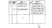
ここで、システム設計者がシナリオ作成時にデザインした図2に示す表示画面11に基づき、表示画面11上において映像表示領域FcやボタンBtの表示範囲(図像の表示範囲)を示す図形データ(代表点座標、形状、サイズ)が予め設定される。この図形データは、図3に示すように、表示画面11を特定する「画面No.」および映像表示領域Fcを特定する「映像表示領域No.」またはボタンBtを特定する「ボタンNo.」と対応付けられ、画面データテーブルTa1として内部記憶装置35に格納される。
Here, based on the
さらに、領域設定手段41は、カメラ2で得られた撮像画像21(図5参照)上で各ボタンBtに対応する範囲に検出領域を設定する機能を有している。要するに、表示画面11上ではボタンBtの範囲が図像により提示され、当該表示画面11を撮像した撮像画像21上では図像に対応する範囲に検出領域が設定されることになる。ここで、撮像画像21上での検出領域の範囲を示すデータ(代表点座標、形状、サイズ)は、各「ボタンNo.」と対応付けて後述するシナリオテーブルTa2(図4参照)の「撮像画像上での検出領域データ」欄に予め格納される。
Further, the area setting means 41 has a function of setting a detection area in a range corresponding to each button Bt on the captured image 21 (see FIG. 5) obtained by the
また、演算部30は、撮像画像21をカメラ2から随時取得しており、当該撮像画像21から所定の判断基準に従って検出領域内の画像の変化の有無を監視する判定手段42としての機能を有している。判定手段42では、検出領域内の画像の変化が検出された場合に、当該検出領域に対応するボタンBtに対してユーザHからの操作入力があったものと判定する。なお、画像の変化の有無をどのように判断するかについては後述する。
In addition, the
さらに演算部30は、判定手段42にて操作入力があったと判定された場合に、判定結果に応じた制御信号を外部に出力することで操作入力に応じた応答処理を実行する出力手段として表示切替手段43を有している。表示切替手段43は、ユーザHからの操作入力に応じてプロジェクタ1の表示画面11を切り替える機能を有する。
Furthermore, when the
以上説明した構成により、表示制御システムは、プロジェクタ1の表示画面11に対するユーザHからの操作入力に応じて、所定の応答処理(ここでは表示画面11の切り替えとする)を行うことになる。
With the configuration described above, the display control system performs a predetermined response process (here, switching of the display screen 11) in response to an operation input from the user H to the
すなわち、上記表示制御システムをある商品の説明に用いる場合を例にすると、処理制御装置3は、プロジェクタ1の表示画面11に、映像表示領域Fcに商品に関する説明を表示させるとともに、次の説明への選択肢を示したボタンBtの図像を表示させる。この状態で、カメラ2では図2に示すような表示画面11を撮像しているため、処理制御装置3は、撮像画像21からボタンBtに対応した検出領域に対するユーザHの操作を検出すると、当該ボタンBtが選択されたものとして、当該ボタンBtに対応付けて設定されている応答処理を実施する。
That is, taking the case where the display control system is used for explanation of a certain product as an example, the
ここでいう応答処理として、以下の説明ではプロジェクタ1、スピーカ7により映像、音といった方法でユーザHに提示することを想定するが、感覚刺激機器8によりユーザHの視覚、聴覚以外の感覚への刺激(たとえば匂い、風、振動等)を応答処理としてユーザHに返すようにしてもよい。応答処理として表示される画像は、静止画、動画のいずれでもよく、また、出力される音は、音声、音楽、環境音(水の流れる音や風の音などの自然音)等、任意に設定される。
In the following description, it is assumed that the response processing here is presented to the user H by the
ここにおいて、操作されるボタンBtと応答処理との対応関係は、設定格納手段としての外部記憶装置36に格納されるシナリオテーブルTa2上で決められている。すなわち、シナリオテーブルTa2では、図4に示すように、「動作」の内容(ここでは、表示画面11を特定する「画面1、画面2、・・・」と、出力音を特定する「音1、音2、・・・」)を規定する「動作No.」ごとに、表示画面11に表示される各ボタンBtを特定する「ボタンNo.」と、応答処理を特定する「ボタン選択時の次の動作」とが対応付けて記憶されている。これにより、演算部30は、ユーザHからの操作入力があったボタンBtの「ボタンNo.」に対応する応答処理をシナリオテーブルTa2の「ボタン選択時の次の動作」欄から読み込み実行する。
Here, the correspondence between the operated button Bt and the response process is determined on the scenario table Ta2 stored in the
また、シナリオテーブルTa2では、上述したように撮像画像21上の検出領域の範囲を表す「撮像画像上での検出領域データ」も各「ボタンNo.」に対応付けて記憶されている。さらに、シナリオテーブルTa2では、各表示画面11中で複数のボタンBtが同時に操作された場合の優先順位を示す「ボタンNo.判定優先順位」、後述する「初期計測時の計測データ格納アドレス」、「検出領域の判定閾値」も各「ボタンNo.」に対応付けて記憶されている。
In the scenario table Ta2, as described above, “detection area data on the captured image” representing the range of the detection area on the captured
図5では、図4のシナリオテーブルTa2を用いた場合の処理制御装置3の動作例を示す。
FIG. 5 shows an operation example of the
すなわち、初期動作である「動作1」では、処理制御装置3は、「画面1」をプロジェクタ1に表示させるとともに、撮像画像21上で「ボタン1」に対応する検出領域を監視する(図5(a))。当該検出領域に対するユーザHからの操作入力を検出すると、処理制御装置3は次動作である「動作2」に移行する。「動作2」では、処理制御装置3は「画面2」をプロジェクタ1に表示させるとともに、撮像画像21上で「ボタン1」〜「ボタン4」に対応する各検出領域をそれぞれ監視する(図5(b))。いずれかの検出領域に対するユーザHからの操作入力を検出すると、処理制御装置3は各ボタンBtに対応付けられている次動作に移行する(図5(c)〜(e))。それ以降も、処理制御装置3はシナリオテーブルTa2におけるボタンBtと応答処理との対応関係に従って動作する。
That is, in the “
以下、上述した構成の表示制御システムの動作について図6のフローチャートを参照して説明する。 Hereinafter, the operation of the display control system having the above-described configuration will be described with reference to the flowchart of FIG.
まず、処理制御装置3は、外部で予め作成されたシナリオテーブルTa2を外部記憶装置36から内部記憶装置35に読み込む(S1)。それから、演算部30では、ユーザHからの操作入力がない状態(以下、「初期状態」という)で各動作を順次実行することにより、各撮像画像21上で各ボタンBtに対応する検出領域を順次設定する。このとき、演算部30は、撮像画像21における各検出領域の画像の特徴量を保管して、当該保管データのアドレスをシナリオテーブルTa2の「初期計測時の計測データ格納アドレス」欄に、各「ボタンNo.」と対応付けて格納する(S2)。
First, the
その後、演算部30は、「動作No.」を表す変数Anを初期値「1」に設定し(S3)、「動作1」の処理である「画面1」の表示と「音1」の出力とを実行する(S4)。このとき、演算部30は、図7に示すように「動作No.」に対応してシナリオテーブルTa2中の「動作」欄に設定された画像データ、音データを読み込み(S21)、表示制御(S22)および音出力(S23)を実行する。この状態で、演算部30は、「ボタンNo.」を表す変数Bnを初期値「1」に設定し(S5)、「ボタン1」に対応する検出領域を設定して(領域設定過程)当該検出領域への操作入力の有無を判定する(S6:判定過程)。
Thereafter, the
ここで、入力なしと判定されれば(S7:No)、演算部30は変数Bnをインクリメントして(S10)、「ボタン2」に対応する検出領域への操作入力の判定処理に移行する。一方、入力有りと判定された場合(S7:Yes)、演算部30は入力があったボタンBtの「ボタンNo.」を記憶し(S9)、変数Bnをインクリメントしてから(S10)、「ボタン2」に対応する検出領域への操作入力の判定処理に移行する。
Here, if it is determined that there is no input (S7: No), the
演算部30は、上述した操作入力の判定処理を、表示中の表示画面11に対応する全てのボタンBtについて(つまり、ボタンデータが終了するまで)繰り返し行う(S11)。なお、操作入力を受けたボタンBtがシナリオテーブルTa2上で終了処理に対応付けられている場合には、当該ボタンBtへの操作入力を受けた時点で表示制御システムの動作を終了する(S8:Yes)。
The
表示中の全てのボタンBtについて操作入力の判定処理が終了すると(S11:Yes)、いずれのボタンBtへの操作入力もなかった場合(S12:No)、変数Bnへの初期値「1」設定処理(S5)に戻り、操作入力の判定処理(S6〜S11)を繰り返す。 When the operation input determination process is completed for all the displayed buttons Bt (S11: Yes), if there is no operation input to any button Bt (S12: No), the initial value “1” is set to the variable Bn. Returning to the process (S5), the operation input determination process (S6 to S11) is repeated.
一方、操作入力があった場合(S12:Yes)、操作入力が1回のみであれば(S13:No)、演算部30はシナリオテーブルTa2を参照して当該ボタンBtに対応付けられた次動作の「動作No.」を変数Anに設定し(S15)、動作の実行処理へと戻り次動作を実行する(S4:出力過程)。また、操作入力が複数あれば(S13:Yes)、演算部30はシナリオテーブルTa2中に予め設定されている優先順位に従ってボタンBtを特定し(S14)、当該ボタンBtに対応付けられた次動作の「動作No.」を動作番号Anに設定し(S15)、動作の実行処理を進める(S4:出力過程)。
On the other hand, when there is an operation input (S12: Yes), if the operation input is only once (S13: No), the
ここにおいて、ボタン(検出領域)Btに対するユーザHからの操作入力の有無を判定する際(S6)に行う画像の変化の有無を判断するための判定手段42の処理について、図8のフローチャートを参照して説明する。 Here, the processing of the determination means 42 for determining the presence / absence of an image change performed when the presence / absence of an operation input from the user H to the button (detection region) Bt is determined (S6) is referred to the flowchart of FIG. To explain.
本実施形態では、演算部30はカメラ2で得られた撮像画像21における検出領域内の画像(特徴量)と、上記初期状態で得られた検出領域内の画像(特徴量)との差分値を用いて、操作入力の判定を行う。ここでは、カメラ2で撮像された濃淡画像(濃淡値を画素値とする画像)をそのまま操作入力の判定に用いることとする。
In the present embodiment, the
すなわち、処理制御装置3は、まず表示画面11をカメラ2で撮像し、得られた撮像画像21を入力画像メモリ34に保存する(S101)。次に、判定手段42は、シナリオテーブルTa2に記憶されている初期状態(操作入力がない状態)の濃淡画像Iiと、入力画像メモリ34内の濃淡画像Iとの間で、検出領域内の画素ごとに画素値の差分をとり、検出領域内の各画素の差分値の合計Siを算出する(S102)。
That is, the
判定手段42は、このように求めた差分値の合計Siと、予め定められている閾値αiとを比較し(S103)、合計Siが閾値αiより大きい場合には操作入力有りと判定し(S104)、それ以外の場合は操作入力なしと判定する(S105)。なお、閾値αiは予め各ボタンBtごとに個別に設定され、シナリオテーブルTa2の「検出領域の判定閾値」欄に格納されている。
The
以上説明した本実施形態の表示制御システムによれば、処理制御装置3は、撮像画像21上で検出領域内の画像の変化の有無によってボタンBtに対する操作入力の有無を判定するので、従来のように撮像画像21からユーザHの指先等の位置を検出する処理が不要となる。したがって、撮像画像21上に設定された検出領域内の画像の変化さえ検出できればよいため、カメラ2として高解像度のものを用いる必要もなく、撮像画像21に対する画像処理も簡単になって、簡易なシステム構成とすることができ、結果的にシステムの導入コスト低減につながる。
According to the display control system of the present embodiment described above, the
また、上述のようにカメラ2で撮像された濃淡画像をそのまま操作入力の判定に用いた場合、撮像画像21に対する前処理が不要になって、計算量が少なく処理の簡略化を図ることができる。ただし、操作入力の判定に環境光の変化の影響を受けやすくなり、環境光変化により撮像画像21全体が明るく(または暗く)なった場合に、操作入力有りと誤検知する可能性がある。
Further, when the grayscale image captured by the
そこで、濃淡画像そのままではなく、濃淡画像の微分強度画像や、濃淡画像を水平、垂直方向にそれぞれ微分し微分値の正、負、ゼロの3値にコード化した3値コード画像を用いて操作入力の判定を行うことも考えられる。 Therefore, instead of using the gray image as it is, the operation is performed using the differential intensity image of the gray image or the ternary code image obtained by differentiating the gray image in the horizontal and vertical directions and coding the differential values into positive, negative, and zero values. It is also conceivable to perform input determination.
微分強度画像を用いる場合、判定手段42は、上記図8の処理S102の前処理として、カメラ2で得られた濃淡画像のうち検出領域内の画像を微分し、周知の方法(たとえば〔「ディジタル画像処理」、CG−ARTS協会、p.114−117〕参照)により微分強度画像を作成する。その後、判定手段42は、作成した微分強度画像と、シナリオテーブルTa2に格納されている初期状態の微分強度画像との間で、検出領域内の画素ごとに画素値の差分をとり、検出領域内の各画素の差分値の合計Sdを算出する。
When the differential intensity image is used, the
判定手段42は、このように求めた差分値の合計Sdと予め定められている閾値αdとを比較し、合計Sdが閾値αdより大きい場合には操作入力有りと判定し、それ以外の場合は操作入力なしと判定する。このように微分強度画像を用いる場合、前処理として微分処理を行う必要があるため計算量が多くなるものの、濃淡画像に比べ環境光の変化の影響を受けにくくなるという利点がある。 The determination means 42 compares the sum Sd of the difference values obtained in this way with a predetermined threshold value αd, and determines that there is an operation input when the total Sd is larger than the threshold value αd, otherwise. It is determined that there is no operation input. Thus, when using a differential intensity image, it is necessary to perform a differential process as a pre-process, which increases the amount of calculation, but has the advantage of being less susceptible to changes in ambient light than a grayscale image.
一方、3値コード画像を用いる場合、判定手段42は、上記図8の処理S102の前処理として、カメラ2で得られた濃淡画像のうち検出領域内の画像を水平方向に微分し、微分値の勾配から正、負、ゼロの3値にコード化した水平方向の3値コード画像を作成する。さらに、判定手段42は、検出領域内の画像を垂直方向に微分し、微分値の勾配から正、負、ゼロの3値にコード化した垂直方向の3値コード画像を作成する。
On the other hand, when the ternary code image is used, the
その後、判定手段42は、水平方向と垂直方向とのそれぞれについて、作成した3値コード画像と、シナリオテーブルTa2に格納されている初期状態の3値コード画像との間で、検出領域内の画素ごとに画素値の差分をとり、検出領域内の各画素の差分値の合計Sh,Svを算出する。
Thereafter, the
判定手段42は、このように求めた水平方向の合計Shが予め定められている閾値αhより大きいか、あるいは垂直方向の合計Svが予め定められている閾値αvより大きい場合には操作入力有りと判定し、それ以外の場合は操作入力なしと判定する。このように3値コード画像を用いる場合、前処理として微分および微分値の勾配に応じたコード化処理が必要となって計算量が多くなるものの、環境光の変化の影響を微分強度画像以上に受けにくくなる。 The determination means 42 determines that there is an operation input when the horizontal direction total Sh thus obtained is larger than a predetermined threshold value αh or when the vertical direction total Sv is larger than a predetermined threshold value αv. In other cases, it is determined that there is no operation input. When a ternary code image is used in this way, coding processing corresponding to the differential and the gradient of the differential value is required as preprocessing, and the amount of calculation increases, but the influence of changes in ambient light is greater than that of the differential intensity image. It becomes difficult to receive.
ところで、本実施形態の処理制御装置3は、表示画面11中のボタンBtへのユーザHからの操作入力を受け付ける通常モードと、検出領域の範囲を指定するための設定モードとの2つの動作モードを有しており、設定モードでは自動設定手段(図示せず)が図9のフローチャートに従って動作する。
By the way, the
すなわち、設定モードにおいて、処理制御装置3はシナリオテーブルTa2および画面データテーブルTa1を外部記憶装置36から内部記憶装置35へ読み込む(S31)。それから、処理制御装置3は、表示画面11の「画面No.」を表す変数Gnに初期値「1」を設定し(S32)、「ボタンNo.」を表す変数Bnにも初期値「1」を設定する(S33)。このとき、プロジェクタ1は、「ボタン1」に対応する図像の画素値(輝度)を最大(ここでは255)、他の領域の画素値を最小(ここではゼロ)とした「画面1」を設定用画像として表示する(S34)。これにより、「画面1」中の「ボタン1」に対応する領域のみが明るく強調表示されることになる。
That is, in the setting mode, the
この状態で、処理制御装置3は、表示画面11をカメラ2で撮像して得られた撮像画像21を読み込み(S35)、当該撮像画像21を予め設定された閾値で2値化し、当該閾値以上の領域を検出領域とする。処理制御装置3は、このようにして決定された当該検出領域の範囲を示すデータ(代表点座標、形状、サイズ)を、「動作No.」および「ボタンNo.」と対応付けてシナリオテーブルTa2の「撮像画像上での検出領域データ」欄に格納する(S36)。
In this state, the
処理制御装置3では、上述の処理を、変数Bn、変数Gnをそれぞれインクリメントしながら(S37,S39)、全ての表示画面11の全てのボタンBtについて検出領域の設定が終了するまで繰り返し行う(S38,S40)。
The
このように、検出領域を設定するボタンBtに対応した領域(図像)とその他の領域とを区別した設定用画像を表示させることで、当該設定用画像を撮像した撮像画像21上の検出領域を安定して抽出可能となり、自動的に設定を行うことができ作業が省力化される。なお、設定用画像において、ボタンBtに対応した領域とその他の領域とは上述したような輝度で区別されるものに限らず、輝度と色との少なくとも一方で区別されていれば、当該設定用画像を撮像した撮像画像21から検出領域を抽出可能となる。
In this way, by displaying the setting image in which the region (image) corresponding to the button Bt for setting the detection region is distinguished from other regions, the detection region on the captured
また、本実施形態では、表示装置の例として画像を投影するプロジェクタ1を示したが、この例に限らず、ディスプレイ装置を表示装置として用い、その表示画面11をカメラ2で撮像するようにしてもよい。これにより、タッチパネルディスプレイではない通常のディスプレイ装置であっても、上記カメラ2および処理制御装置3と組み合わせることで、ユーザHによる操作入力に対して種々の動作を行う表示制御システムを構成することができる。なお、ここでいうディスプレイ装置は、ブラウン管、液晶ディスプレイ、プラズマディスプレイ、背面投影型ディスプレイ等のディスプレイ装置全般を意味する。
In the present embodiment, the
(実施形態2)
本実施形態の表示制御システムは、プロジェクタ1により表示される表示画面11上に実際に存在する物体を操作入力の対象として用いる点が実施形態1の表示制御システムと相違する。
(Embodiment 2)
The display control system according to the present embodiment is different from the display control system according to the first embodiment in that an object that actually exists on the
すなわち、物体を操作入力のためのボタンBtとして用いるために、当該物体を含む一定の照明領域には照明の代わりとなるような一様な映像の表示を行う。これにより、前記照明範囲に映し出される映像が、ユーザHからの操作入力を受付可能なボタンBtの範囲を示す図像を構成する。判定手段42では、撮像画像21において上記照明領域(図像)に対応する範囲に検出領域を設定し操作入力の監視を行う。つまり、ユーザHが照明領域内の物体に手をかざしたり、物体を手に取ったりすると、判定手段42は、画像の変化を検出してユーザHからの操作入力があったものと判定する。
In other words, in order to use an object as the button Bt for operation input, a uniform image is displayed in a certain illumination area including the object instead of illumination. As a result, the image displayed in the illumination range constitutes an image showing the range of the button Bt that can accept an operation input from the user H. The
本実施形態の表示制御システムの動作例を図10を参照して説明する。図10の例では、表示画面11上に3個の物体Ob1〜Ob3(以下、各々を特に区別しないときには単に「物体Ob」という)が存在する。
An operation example of the display control system of this embodiment will be described with reference to FIG. In the example of FIG. 10, there are three objects Ob <b> 1 to Ob <b> 3 (hereinafter simply referred to as “object Ob” when not distinguished from each other) on the
処理制御装置3は、まず各物体Ob1〜Ob3にそれぞれ対応する照明領域La1〜La3(以下、各々を特に区別しないときには単に「照明領域La」という)を照明するように構成された「画面1」をプロジェクタ1に表示させるとともに、撮像画像21上で各照明領域La1〜La3を検出領域として監視する(図10(a))。ここで、いずれかの物体Obに対応する照明領域(検出領域)Laに対してユーザHからの操作入力を検出すると、処理制御装置3は次動作に移行する。
The
このときの表示画面11は、前画面で選択された照明領域Laのみ照明するとともに、当該照明領域Laに対応する物体Obの機能等の説明画面に切り替えるためのボタンBt1〜Bt3を表示するように構成される(図10(b)〜(d))。この状態で、処理制御装置3は、撮像画像21上でボタンBt1〜ボタンBt3に対応する各検出領域をそれぞれ監視し、ユーザHからの操作入力を検出すると、各ボタンBtに対応付けられている次動作に移行する(図10(e)〜(j))。なお、図10において、破線で示した照明領域La1〜La3は、操作入力の判定に用いない(つまり照明のみを行う)ため、対応する検出領域が設定されていない状態の照明領域を示している。
The
ここで、操作入力の判定に用いる照明領域は、図3の画面データテーブルTa1の「ボタンNo.」に対応する「図形データ」欄にデータを設定し、操作入力の判定に用いない(つまり照明のみを行う)照明領域は「映像表示領域No.」に対応する「図形データ」欄にデータを設定する。 Here, the illumination area used for the determination of the operation input is set in the “graphic data” field corresponding to the “button No.” in the screen data table Ta1 of FIG. In the illumination area, data is set in the “graphic data” column corresponding to “video display area No.”.
以上説明したように、空間に実在する物体をユーザHからの操作入力に用いることにより、表示画面11上の図像のみを操作入力の対象とする場合に比べて、操作入力の対象がユーザHに認識されやすくなるという利点がある。
As described above, by using an object that exists in the space for the operation input from the user H, the operation input target is set to the user H compared to the case where only the icon image on the
ところで、本実施形態においては、操作入力の判定の処理も実施形態1とは異なっており、以下、当該判定処理について図11のフローチャートを参照して説明する。 By the way, in this embodiment, the operation input determination process is also different from that of the first embodiment, and the determination process will be described below with reference to the flowchart of FIG.
本実施形態では、判定手段42は、カメラ2で得られた撮像画像21における検出領域内のエッジ画像からエッジ数を求め、初期状態と比較したときのエッジ数の変化量が所定の閾値を超える場合に操作入力があったと判断する。
In the present embodiment, the
すなわち、処理制御装置3は、まず表示画面11をカメラ2で撮像し(S41)、得られた撮像画像21を入力画像メモリ34に保存した上で、検出領域内のエッジ画像を作成する(S42)。ここで、エッジ画像の作成には周知のCannyのエッジ検出(〔「ディジタル画像処理」、CG−ARTS協会、p.209−210〕参照)を使用する。
That is, the
次に、判定手段42は、検出領域内のエッジ画素の合計数Eを算出し(S43)、当該合計数Eと、シナリオテーブルTa2に記憶されている初期状態のエッジ画素の合計数Eiとの差の絶対値Dを算出する(S44)。判定手段42は、このように求めた絶対値Dと予め定められている閾値βとを比較し(S45)、絶対値Dが閾値βより大きい場合には操作入力有りと判定し(S46)、それ以外の場合は操作入力なしと判定する(S47)。
Next, the
この構成によれば、操作入力の有無は、画素ごとの差分ではなく検出領域内におけるエッジ画素の総数によって判定されるので、ユーザHが物体を一旦手に取ったがすぐに元の位置に戻したような場合に、検出領域内の物体に多少の位置ずれがあっても許容されることになる。すなわち、検出領域内で物体の位置が僅かに変化しただけの場合に、ユーザHによる操作入力があったものとの誤検出を防ぐことができる。 According to this configuration, the presence / absence of an operation input is determined by the total number of edge pixels in the detection region, not by the difference for each pixel, so that the user H once picks up the object but immediately returns it to the original position. In such a case, even if there is a slight misalignment in the object in the detection area, it is allowed. That is, it is possible to prevent erroneous detection of an operation input by the user H when the position of the object is slightly changed in the detection area.
その他の構成および機能は実施形態1と同様である。 Other configurations and functions are the same as those of the first embodiment.
(実施形態3)
本実施形態の表示制御システムは、入力内容を確認する確認機能が付加されている点が実施形態1の表示制御システムと相違する。
(Embodiment 3)
The display control system according to the present embodiment is different from the display control system according to the first embodiment in that a confirmation function for confirming input contents is added.
ここで、判定手段42は、表示画面の切り替えの前後において撮像画像21内の同一位置に設定された検出領域で連続して操作入力を検出した場合、当該検出領域に対するユーザHからの操作入力を確定する前にユーザHに対して確認操作を要求する操作確認機能を有する。判定手段42は、ユーザHからの確認操作があったときのみ前記操作入力を確定する。
Here, when the
本実施形態では、操作入力の検出処理(図6のS1〜S14)後の処理が実施形態1と異なるため、以下、操作入力の検出後の処理について図12のフローチャートを参照して説明する。なお、図12に示す処理(S41〜S44)は図6の処理S14と処理S15との間に挿入されることになる。 In the present embodiment, the process after the operation input detection process (S1 to S14 in FIG. 6) is different from that in the first embodiment. Therefore, the process after the operation input is detected will be described below with reference to the flowchart in FIG. Note that the processing (S41 to S44) shown in FIG. 12 is inserted between the processing S14 and the processing S15 in FIG.
すなわち、演算部30は、操作入力の検出処理(図6のS1〜S14)終了後、1回でも操作入力があると、当該ボタンBtに対応する応答処理の実行に移る前に、操作されたボタンBtが前回操作されたボタンBtと同一である(つまり、同一のボタンBtが連続して操作された)か否かを判断する(S41)。
That is, when the operation input detection process (S1 to S14 in FIG. 6) is completed, the
ここで、同一であると判断されると、ユーザHに対して当該ボタンBtの操作入力を確認する確認モードに移行する。確認モードでは、演算部30は確認対象となるボタンBtの「ボタンNo.」を表示するとともに、このボタンBtの操作を確定するか否かを決定する確認操作をユーザHに要求するメッセージ(たとえば「このNo.で良ければ入力ボタンから手を反してください。」)を表示領域に表示する(S42)。このとき、判定手段42は、確認中のボタンBtに対応する検出領域のみを操作入力の検出対象として、操作入力が継続して検出されるか否かを判断する(S43)。ここで、継続して操作入力が検出される場合には(S44:Yes)引き続き前記メッセージを表示し、操作入力が検出されなくなれば(S44:No)次の動作(図6のS15)に移行する。
If it is determined that they are the same, the mode shifts to a confirmation mode in which the user H confirms the operation input of the button Bt. In the confirmation mode, the
以上説明した構成によれば、ユーザHがボタンBt上に手を置いたままにしたり、ボタンBt上に物体を放置したりすることで、ユーザHの意に反してボタンBtが操作され続けることによる誤操作を回避できる。 According to the configuration described above, the user B keeps operating the button Bt against the intention of the user H by leaving his / her hand on the button Bt or leaving an object on the button Bt. Can avoid misoperation.
その他の構成および機能は実施形態1と同様である。 Other configurations and functions are the same as those of the first embodiment.
1 プロジェクタ(表示装置)
2 カメラ(撮像装置)
3 処理制御装置
11 表示画面
41 領域設定手段
42 判定手段
43 表示切替手段(出力手段)
H ユーザ
1 Projector (display device)
2 Camera (imaging device)
3
H user
Claims (7)
処理制御装置は、
表示装置に対し表示画面のうち撮像装置の撮像範囲に含まれる位置にユーザからの操作入力を受付可能な範囲を示す図像を少なくとも1つ表示させるとともに、撮像画像上で図像に対応する範囲に検出領域を設定する領域設定手段と、
随時取得される撮像画像から所定の判断基準に従って検出領域内の画像の変化の有無を監視し、画像の変化が検出された場合に当該検出領域に対してユーザからの操作入力があったものと判定する判定手段と、
判定手段での判定結果に応じた制御信号を外部に出力する出力手段と、
前記撮像画像中の前記検出領域の範囲を決定するための設定モードにおいて、前記表示装置に輝度と色との少なくとも一方を前記図像となる範囲と他の範囲とで区別した設定用画像を表示させるとともに、設定用画像を撮像した前記撮像画像から図像となる範囲を抽出し抽出結果から検出領域の範囲を自動的に決定する自動設定手段とを有する
ことを特徴とする表示制御システム。 Display device for displaying image, imaging device for obtaining image including at least part of display screen of display device in imaging range, display control of display device and processing control for image processing of captured image obtained by imaging device With the device,
The processing control device
The display device displays at least one icon indicating a range in which an operation input from the user can be received at a position included in the imaging range of the imaging device on the display screen, and is detected in the range corresponding to the icon on the captured image. Area setting means for setting an area;
The presence or absence of a change in the image in the detection area is monitored from a captured image acquired at any time according to a predetermined criterion, and when a change in the image is detected, there is an operation input from the user to the detection area Determination means for determining;
Output means for outputting a control signal according to the determination result of the determination means to the outside ;
In the setting mode for determining the range of the detection area in the captured image, the display device displays a setting image in which at least one of luminance and color is distinguished from the range to be the image and the other range. A display control system comprising: automatic setting means for extracting a range to be a graphic from the captured image obtained by capturing the setting image and automatically determining the range of the detection region from the extraction result .
処理制御装置は、
表示装置に対し表示画面のうち撮像装置の撮像範囲に含まれる位置にユーザからの操作入力を受付可能な範囲を示す図像を少なくとも1つ表示させるとともに、撮像画像上で図像に対応する範囲に検出領域を設定する領域設定手段と、
随時取得される撮像画像から所定の判断基準に従って検出領域内の画像の変化の有無を監視し、画像の変化が検出された場合に当該検出領域に対してユーザからの操作入力があったものと判定する判定手段と、
判定手段での判定結果に応じた制御信号を外部に出力する出力手段と、
前記表示装置の表示画面を切り替える表示切替手段とを有し、
前記判定手段は、前記表示画面の切り替えの前後において前記撮像画像内の同一位置に設定された前記検出領域で連続して前記画像の変化を検出した場合、当該検出領域に対するユーザからの操作入力を確定する前にユーザに対して確認操作を要求し、ユーザからの確認操作があったときのみ前記操作入力を確定する操作確認機能を有する
ことを特徴とする表示制御システム。 Display device for displaying image, imaging device for obtaining image including at least part of display screen of display device in imaging range, display control of display device and processing control for image processing of captured image obtained by imaging device With the device,
The processing control device
The display device displays at least one icon indicating a range in which an operation input from the user can be received at a position included in the imaging range of the imaging device on the display screen, and is detected in the range corresponding to the icon on the captured image. Area setting means for setting an area;
The presence or absence of a change in the image in the detection area is monitored from a captured image acquired at any time according to a predetermined criterion, and when a change in the image is detected, there is an operation input from the user to the detection area Determination means for determining;
Output means for outputting a control signal according to the determination result of the determination means to the outside;
Display switching means for switching the display screen of the display device,
When the determination unit detects a change in the image continuously in the detection region set at the same position in the captured image before and after switching the display screen, the determination unit receives an operation input from the user to the detection region. Table示制control system that is characterized by having an operation confirmation function for determining the operation input only when requesting confirmation operation to the user, there is a confirmation operation from the user before committing.
表示装置に対し表示画面のうち撮像装置の撮像範囲に含まれる位置にユーザからの操作入力を受付可能な範囲を示す図像を少なくとも1つ表示させるとともに、撮像画像上で図像に対応する範囲に検出領域を設定する領域設定過程と、
随時取得される撮像画像から所定の判断基準に従って検出領域内の画像の変化の有無を監視し、画像の変化が検出された場合に当該検出領域に対してユーザからの操作入力があったものと判定する判定過程と、
判定過程での判定結果に応じて表示装置の表示画面を切り替える出力過程とを有し、
前記撮像画像中の前記検出領域の範囲を決定する際、前記表示装置に輝度と色との少なくとも一方を前記図像となる範囲と他の範囲とで区別した設定用画像を表示させるとともに、設定用画像を撮像した前記撮像画像から図像となる範囲を抽出し抽出結果から検出領域の範囲を自動的に決定する
ことを特徴とする表示制御方法。 A display control method that uses a display device that displays an image and an imaging device that acquires an image including at least a part of the display screen of the display device in an imaging range, and that accepts an operation input from a user on the display screen of the display device. And
The display device displays at least one icon indicating a range in which an operation input from the user can be received at a position included in the imaging range of the imaging device on the display screen, and is detected in the range corresponding to the icon on the captured image. An area setting process for setting an area;
The presence or absence of a change in the image in the detection area is monitored from a captured image acquired at any time according to a predetermined criterion, and when a change in the image is detected, there is an operation input from the user to the detection area A judging process for judging,
An output process for switching the display screen of the display device according to the determination result in the determination process,
When determining the range of the detection area in the captured image, the display device displays a setting image in which at least one of luminance and color is distinguished from the range to be the graphic and the other range, and for setting Viewing control how to characterized by automatically determining the range of the detection area from the extracted extraction result a range of the iconography from the captured image of the captured image.
表示装置に対し表示画面のうち撮像装置の撮像範囲に含まれる位置にユーザからの操作入力を受付可能な範囲を示す図像を少なくとも1つ表示させるとともに、撮像画像上で図像に対応する範囲に検出領域を設定する領域設定過程と、
随時取得される撮像画像から所定の判断基準に従って検出領域内の画像の変化の有無を監視し、画像の変化が検出された場合に当該検出領域に対してユーザからの操作入力があったものと判定する判定過程と、
判定過程での判定結果に応じて表示装置の表示画面を切り替える出力過程とを有し、
前記判定過程では、前記表示画面の切り替えの前後において前記撮像画像内の同一位置に設定された前記検出領域で連続して前記画像の変化を検出した場合、当該検出領域に対するユーザからの操作入力を確定する前にユーザに対して確認操作を要求し、ユーザからの確認操作があったときのみ前記操作入力を確定する
ことを特徴とする表示制御方法。 A display control method that uses a display device that displays an image and an imaging device that acquires an image including at least a part of the display screen of the display device in an imaging range, and that accepts an operation input from a user on the display screen of the display device. And
The display device displays at least one icon indicating a range in which an operation input from the user can be received at a position included in the imaging range of the imaging device on the display screen, and is detected in the range corresponding to the icon on the captured image. An area setting process for setting an area;
The presence or absence of a change in the image in the detection area is monitored from a captured image acquired at any time according to a predetermined criterion, and when a change in the image is detected, there is an operation input from the user to the detection area A judging process for judging,
Possess an output process for switching the display screen of the display device according to the determination result of the determination process,
In the determination process, when a change in the image is continuously detected in the detection area set at the same position in the captured image before and after switching of the display screen, an operation input from the user to the detection area is performed. A display control method, wherein a confirmation operation is requested to the user before confirmation, and the operation input is confirmed only when the confirmation operation is performed by the user .
Priority Applications (1)
| Application Number | Priority Date | Filing Date | Title |
|---|---|---|---|
| JP2009289708A JP5244084B2 (en) | 2009-12-21 | 2009-12-21 | Display control system and display control method |
Applications Claiming Priority (1)
| Application Number | Priority Date | Filing Date | Title |
|---|---|---|---|
| JP2009289708A JP5244084B2 (en) | 2009-12-21 | 2009-12-21 | Display control system and display control method |
Publications (2)
| Publication Number | Publication Date |
|---|---|
| JP2011129068A JP2011129068A (en) | 2011-06-30 |
| JP5244084B2 true JP5244084B2 (en) | 2013-07-24 |
Family
ID=44291560
Family Applications (1)
| Application Number | Title | Priority Date | Filing Date |
|---|---|---|---|
| JP2009289708A Active JP5244084B2 (en) | 2009-12-21 | 2009-12-21 | Display control system and display control method |
Country Status (1)
| Country | Link |
|---|---|
| JP (1) | JP5244084B2 (en) |
Families Citing this family (5)
| Publication number | Priority date | Publication date | Assignee | Title |
|---|---|---|---|---|
| US9317171B2 (en) * | 2013-04-18 | 2016-04-19 | Fuji Xerox Co., Ltd. | Systems and methods for implementing and using gesture based user interface widgets with camera input |
| JP6844159B2 (en) | 2016-09-12 | 2021-03-17 | セイコーエプソン株式会社 | Display device and control method of display device |
| KR102640281B1 (en) | 2016-10-13 | 2024-02-26 | 한화비전 주식회사 | Method of controlling surveillance camera and surveillance system adopting the method |
| JP6822209B2 (en) * | 2017-02-24 | 2021-01-27 | セイコーエプソン株式会社 | Projector and projector control method |
| JP2019053769A (en) * | 2018-12-04 | 2019-04-04 | シャープ株式会社 | Touch detection apparatus, touch detection system, touch detection method, and program |
Family Cites Families (4)
| Publication number | Priority date | Publication date | Assignee | Title |
|---|---|---|---|---|
| JP2005141151A (en) * | 2003-11-10 | 2005-06-02 | Seiko Epson Corp | Projector and method for setting projector function |
| WO2006038577A1 (en) * | 2004-10-05 | 2006-04-13 | Nikon Corporation | Electronic device |
| JP2008181304A (en) * | 2007-01-24 | 2008-08-07 | Sony Corp | Information processor, method, and program |
| JP4835538B2 (en) * | 2007-08-10 | 2011-12-14 | パナソニック電工株式会社 | Image display device |
-
2009
- 2009-12-21 JP JP2009289708A patent/JP5244084B2/en active Active
Also Published As
| Publication number | Publication date |
|---|---|
| JP2011129068A (en) | 2011-06-30 |
Similar Documents
| Publication | Publication Date | Title |
|---|---|---|
| US10671175B2 (en) | Image processing apparatus, image processing method, and program product to control a display to display an image generated based on a manipulation target image | |
| US10055081B2 (en) | Enabling visual recognition of an enlarged image | |
| JP2013140533A5 (en) | ||
| JP5244084B2 (en) | Display control system and display control method | |
| KR20110026068A (en) | Apparatus and method for providing poi information in portable terminal | |
| JP2013134661A5 (en) | Display device, display system, and data supply method for display device | |
| JP2017533602A (en) | Switching between electronic device cameras | |
| US10841481B2 (en) | Control apparatus, method of controlling the same and program | |
| CN108628402B (en) | Display device with input function | |
| MX2014008355A (en) | Display apparatus and controlling method thereof. | |
| JP5030748B2 (en) | Video display system | |
| JP2011053587A (en) | Image processing device | |
| JP6117470B2 (en) | Display device, projector, image display method, and display system | |
| US10623610B2 (en) | Display processing device and display processing method | |
| JP2015192310A (en) | Projection system, portable equipment, program, and control method of portable equipment | |
| JP5229928B1 (en) | Gaze position specifying device and gaze position specifying program | |
| JP2012090785A (en) | Electronic endoscope apparatus | |
| JP2012156797A (en) | Image processing apparatus and image processing method | |
| JP5015121B2 (en) | Imaging device | |
| CN109343771B (en) | Electronic equipment, control method and control method of electronic equipment | |
| JP2006250536A (en) | Pattern recognition device and pattern recognition method | |
| JP5109340B2 (en) | Image processing apparatus, image display method, program for causing computer to execute image display method, and recording medium recording the program | |
| JP2009098231A (en) | Display device | |
| JP2009021043A (en) | Electronic equipment | |
| KR100762179B1 (en) | Method for identifying point of broadcast receiving device with zoom-in function |
Legal Events
| Date | Code | Title | Description |
|---|---|---|---|
| A711 | Notification of change in applicant |
Free format text: JAPANESE INTERMEDIATE CODE: A712 Effective date: 20120118 |
|
| A621 | Written request for application examination |
Free format text: JAPANESE INTERMEDIATE CODE: A621 Effective date: 20120712 |
|
| A977 | Report on retrieval |
Free format text: JAPANESE INTERMEDIATE CODE: A971007 Effective date: 20121212 |
|
| A131 | Notification of reasons for refusal |
Free format text: JAPANESE INTERMEDIATE CODE: A131 Effective date: 20121218 |
|
| A521 | Request for written amendment filed |
Free format text: JAPANESE INTERMEDIATE CODE: A523 Effective date: 20130218 |
|
| TRDD | Decision of grant or rejection written | ||
| A01 | Written decision to grant a patent or to grant a registration (utility model) |
Free format text: JAPANESE INTERMEDIATE CODE: A01 Effective date: 20130312 |
|
| A61 | First payment of annual fees (during grant procedure) |
Free format text: JAPANESE INTERMEDIATE CODE: A61 Effective date: 20130405 |
|
| FPAY | Renewal fee payment (event date is renewal date of database) |
Free format text: PAYMENT UNTIL: 20160412 Year of fee payment: 3 |
|
| R150 | Certificate of patent or registration of utility model |
Free format text: JAPANESE INTERMEDIATE CODE: R150 Ref document number: 5244084 Country of ref document: JP Free format text: JAPANESE INTERMEDIATE CODE: R150 |